WO2018164023A1 - 高圧ポンプ - Google Patents
高圧ポンプ Download PDFInfo
- Publication number
- WO2018164023A1 WO2018164023A1 PCT/JP2018/008213 JP2018008213W WO2018164023A1 WO 2018164023 A1 WO2018164023 A1 WO 2018164023A1 JP 2018008213 W JP2018008213 W JP 2018008213W WO 2018164023 A1 WO2018164023 A1 WO 2018164023A1
- Authority
- WO
- WIPO (PCT)
- Prior art keywords
- valve
- passage
- stopper
- discharge valve
- fuel
- Prior art date
Links
Images


Classifications
-
- F—MECHANICAL ENGINEERING; LIGHTING; HEATING; WEAPONS; BLASTING
- F16—ENGINEERING ELEMENTS AND UNITS; GENERAL MEASURES FOR PRODUCING AND MAINTAINING EFFECTIVE FUNCTIONING OF MACHINES OR INSTALLATIONS; THERMAL INSULATION IN GENERAL
- F16K—VALVES; TAPS; COCKS; ACTUATING-FLOATS; DEVICES FOR VENTING OR AERATING
- F16K15/00—Check valves
- F16K15/02—Check valves with guided rigid valve members
- F16K15/06—Check valves with guided rigid valve members with guided stems
- F16K15/063—Check valves with guided rigid valve members with guided stems the valve being loaded by a spring
-
- F—MECHANICAL ENGINEERING; LIGHTING; HEATING; WEAPONS; BLASTING
- F02—COMBUSTION ENGINES; HOT-GAS OR COMBUSTION-PRODUCT ENGINE PLANTS
- F02M—SUPPLYING COMBUSTION ENGINES IN GENERAL WITH COMBUSTIBLE MIXTURES OR CONSTITUENTS THEREOF
- F02M59/00—Pumps specially adapted for fuel-injection and not provided for in groups F02M39/00 -F02M57/00, e.g. rotary cylinder-block type of pumps
- F02M59/44—Details, components parts, or accessories not provided for in, or of interest apart from, the apparatus of groups F02M59/02 - F02M59/42; Pumps having transducers, e.g. to measure displacement of pump rack or piston
- F02M59/46—Valves
- F02M59/462—Delivery valves
-
- F—MECHANICAL ENGINEERING; LIGHTING; HEATING; WEAPONS; BLASTING
- F02—COMBUSTION ENGINES; HOT-GAS OR COMBUSTION-PRODUCT ENGINE PLANTS
- F02M—SUPPLYING COMBUSTION ENGINES IN GENERAL WITH COMBUSTIBLE MIXTURES OR CONSTITUENTS THEREOF
- F02M63/00—Other fuel-injection apparatus having pertinent characteristics not provided for in groups F02M39/00 - F02M57/00 or F02M67/00; Details, component parts, or accessories of fuel-injection apparatus, not provided for in, or of interest apart from, the apparatus of groups F02M39/00 - F02M61/00 or F02M67/00; Combination of fuel pump with other devices, e.g. lubricating oil pump
- F02M63/0012—Valves
- F02M63/007—Details not provided for in, or of interest apart from, the apparatus of the groups F02M63/0014 - F02M63/0059
- F02M63/0077—Valve seat details
-
- F—MECHANICAL ENGINEERING; LIGHTING; HEATING; WEAPONS; BLASTING
- F02—COMBUSTION ENGINES; HOT-GAS OR COMBUSTION-PRODUCT ENGINE PLANTS
- F02B—INTERNAL-COMBUSTION PISTON ENGINES; COMBUSTION ENGINES IN GENERAL
- F02B33/00—Engines characterised by provision of pumps for charging or scavenging
-
- F—MECHANICAL ENGINEERING; LIGHTING; HEATING; WEAPONS; BLASTING
- F02—COMBUSTION ENGINES; HOT-GAS OR COMBUSTION-PRODUCT ENGINE PLANTS
- F02M—SUPPLYING COMBUSTION ENGINES IN GENERAL WITH COMBUSTIBLE MIXTURES OR CONSTITUENTS THEREOF
- F02M59/00—Pumps specially adapted for fuel-injection and not provided for in groups F02M39/00 -F02M57/00, e.g. rotary cylinder-block type of pumps
- F02M59/20—Varying fuel delivery in quantity or timing
- F02M59/36—Varying fuel delivery in quantity or timing by variably-timed valves controlling fuel passages to pumping elements or overflow passages
- F02M59/366—Valves being actuated electrically
- F02M59/368—Pump inlet valves being closed when actuated
Definitions
- This disclosure relates to a high pressure pump.
- a high-pressure pump attached to an internal combustion engine which pressurizes and discharges fuel to supply the internal combustion engine is known.
- a discharge valve portion is provided in a discharge passage through which fuel pressurized and discharged in a pressurizing chamber flows.
- the discharge valve section allows the flow of fuel from the pressurizing chamber side to the discharge passage side and regulates the flow of fuel from the discharge passage side to the pressurizing chamber side.
- the discharge valve portion of Patent Document 1 includes a cylindrical portion, a disc-shaped valve whose outer edge is in sliding contact with the inner peripheral wall of the cylindrical portion and guided in axial movement, and a pressurizing chamber of the valve when contacting the valve.
- the stopper is formed integrally with the cylindrical portion so as to close the end of the cylindrical portion.
- the valve seat with which the valve abuts is formed on the inner wall of the housing.
- the valve seat is formed in the housing, and the cylindrical portion and the stopper are integrally formed to simplify the configuration.
- An object of the present disclosure is to provide a high-pressure pump including a small and simple valve unit.
- the high-pressure pump includes a housing, a cylinder portion, a seat portion, a valve, and a stopper.
- the housing has a pressurizing chamber in which fuel is pressurized.
- the cylinder portion forms a discharge passage through which fuel discharged from the pressurizing chamber flows.
- the seat portion includes an upstream passage connecting the discharge passage and the pressurizing chamber, and a valve seat formed on the discharge passage side of the upstream passage.
- the valve is formed between a valve main body that is provided so that an outer edge portion is in sliding contact with the inner peripheral wall of the cylindrical portion and guided in the axial direction so as to contact the valve seat, and the inner peripheral wall of the cylindrical portion of the valve main body. It has the 1st channel
- the stopper is made of a member separate from the cylinder, and is a stopper body that is provided on the opposite side of the valve seat from the valve.
- the stopper can move when the valve is in contact with the valve. It has a regulation surface and a second passage formed in the stopper body and capable of flowing the fuel on the valve side to the side opposite to the valve with respect to the stopper body.
- the first passage is located on the valve seat side with respect to the movement restricting surface.
- the second passage is located on the side opposite to the valve seat with respect to the movement restricting surface.
- the valve body is guided in the axial direction by the outer edge portion being in sliding contact with the inner peripheral wall of the cylindrical portion.
- the first passage through which the fuel on the valve seat side can flow to the opposite side of the valve seat with respect to the valve main body is formed between the inner peripheral wall of the tubular portion of the valve main body.
- the stopper is formed with the member different from a cylinder part.
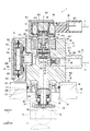
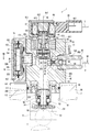
- FIG. 1 is a cross-sectional view showing a high-pressure pump according to a first embodiment.
- FIG. 2 is a cross-sectional view showing the high-pressure pump according to the first embodiment
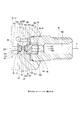
- FIG. 3 is a cross-sectional view showing a discharge valve portion of the high-pressure pump according to the first embodiment.
- FIG. 4 is a cross-sectional view showing a discharge valve portion of the high-pressure pump according to the first embodiment, and shows a valve open state.
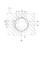
- 5 is a cross-sectional view taken along line VV in FIG.
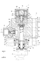
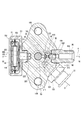
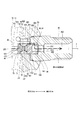
- FIG. 6 is a cross-sectional view showing a high-pressure pump according to the second embodiment.
- FIG. 7 is a cross-sectional view taken along line VII-VII in FIG.
- FIG. 8 is a cross-sectional view showing a discharge valve portion of the high-pressure pump according to the second embodiment.
- FIG. 9 is a cross-sectional view showing a discharge valve portion of the high-pressure pump according to the second embodiment, and is a view showing a valve open state.
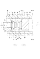
- FIG. 10 is a cross-sectional view showing the discharge valve portion of the high-pressure pump according to the third embodiment
- FIG. 11 is a cross-sectional view showing a discharge valve portion of the high-pressure pump according to the third embodiment, and is a view showing a valve open state.
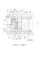
- FIG. 12 is a cross-sectional view showing a discharge valve portion of the high-pressure pump according to the fourth embodiment
- FIG. 13 is sectional drawing which shows the discharge valve part of the high pressure pump by 4th Embodiment, Comprising: It is a figure which shows a valve opening state.
- the high-pressure pump 1 is provided in a vehicle not shown.
- the high-pressure pump 1 is a pump that supplies fuel at a high pressure to an engine 2 as an internal combustion engine, for example.
- the fuel that the high-pressure pump 1 supplies to the engine 2 is, for example, gasoline. That is, the fuel supply target of the high-pressure pump 1 is a gasoline engine.
- the fuel stored in a fuel tank (not shown) is supplied to the high-pressure pump 1 via a pipe 3 by a fuel pump (not shown) (see FIG. 2).
- the high-pressure pump 1 pressurizes the fuel supplied from the fuel pump and discharges it to a fuel rail (not shown) via the pipe 4 (see FIG. 1). Thereby, the fuel in the fuel rail is accumulated and supplied to the engine 2 from the fuel injection valve connected to the fuel rail.
- the high-pressure pump 1 includes a housing 10, a pulsation damper 16, a suction valve unit 30, a plunger 50, a spring 54 as a plunger urging member, an electromagnetic drive unit 60, a discharge valve unit 40, and the like.
- the housing 10 includes a housing main body 11, an inlet portion 12, a discharge portion 13, a damper chamber forming portion 15, a seat upper 14 and the like.
- the housing main body 11 is formed in a substantially cylindrical shape with a metal such as stainless steel.
- the housing body 11 includes an upper concave portion 101, a lower concave portion 102, an inflow concave portion 103, a damper concave portion 105, an extended cylindrical portion 111, an extended cylindrical portion 112, an inflow portion 201, a plunger hole 202, a pressurizing chamber 203, a suction passage 204, a discharge A passage 205, a fuel reservoir 207, an inflow side upper passage 211, an inflow side lower passage 212, a damper side upper passage 221, a damper side lower passage 222, a connection passage 231 and the like are provided.
- the upper recess 101 is formed so as to be recessed in a circular shape from one end face of the housing body 11 to the other end face.
- the lower recessed portion 102 is formed so as to be recessed in an annular shape from the other end surface of the housing body 11 to the one end surface side.
- the upper concave portion 101 and the lower concave portion 102 are formed coaxially.
- the expression “coaxial” is not limited to the state of being strictly coaxial, but also includes the state where the axes are slightly shifted from each other. In addition, when the two members are provided coaxially, the axes may be slightly shifted depending on the state of use. same as below.
- the inflow recess 103 is formed so as to be recessed in a circular shape from the side wall between one end surface and the other end surface of the housing body 11 toward the center of the housing body 11.
- the damper recess 105 is formed so as to be recessed in a circular shape from the side wall between one end surface and the other end surface of the housing body 11 toward the center of the housing body 11.
- the inflow recess 103 and the damper recess 105 are formed so that their axes are orthogonal to the axes of the upper recess 101 and the lower recess 102.
- the expression “orthogonal” is not limited to two straight lines that are strictly orthogonal, but includes two straight lines that are slightly non-orthogonal. same as below.
- the extending cylinder portion 111 is formed on the other end surface of the housing body 11 so as to extend in a substantially cylindrical shape from the inside of the lower recess 102.
- the extending cylindrical portion 112 is formed on the other end surface of the housing body 11 so as to extend in a substantially cylindrical shape from the outside of the lower recessed portion 102.
- the inflow portion 201 is formed on the bottom side of the inflow recess 103.
- the plunger hole 202 is formed in a substantially cylindrical shape so as to connect the bottom of the upper recess 101 and the other end surface of the housing body 11.
- the plunger hole 202 is formed coaxially with the upper recess 101 and the lower recess 102.
- the pressurizing chamber 203 is formed at the end of the plunger hole 202 on the upper recess 101 side.
- the suction passage 204 is formed on the pressurization chamber 203 side of the upper recess 101 and is connected to the pressurization chamber 203.
- the discharge passage 205 is formed to extend outward in the radial direction of the housing body 11.
- the discharge passage 205 is formed such that its axis is orthogonal to the axis Ax1 of the plunger hole 202.
- the discharge passage 205 is formed inside a cylinder portion 41 of the discharge valve portion 40 which will be described later.
- the fuel reservoir 207 is formed in the lower recess 102. That is, the fuel reservoir 207 is formed in an annular shape.
- the inflow side upper passage 211 is formed so as to connect the inflow portion 201 and the suction passage 204.
- two inflow-side upper passages 211 are formed in the housing body 11 such that the axes are parallel to the axis Ax1 of the plunger hole 202.
- the suction passage 204 is connected to the pressurizing chamber 203 and is formed to communicate with the inflow portion 201 via the inflow side upper passage 211.
- the expression “parallel” is not limited to two straight lines that are strictly parallel, but also includes two straight lines that are slightly non-parallel. same as below.
- the inflow side lower passage 212 is formed to connect the inflow portion 201 and the fuel reservoir portion 207.
- one inflow side lower passage 212 is formed in the housing body 11 so that the axis is parallel to the axis Ax1 of the plunger hole 202.
- the damper-side upper passage 221 is formed so as to connect the space inside the damper recess 105 and the suction passage 204.
- two damper-side upper passages 221 are formed in the housing body 11 so that the shafts are parallel to the shaft Ax1 of the plunger hole 202.
- the damper-side lower passage 222 is formed to connect the space inside the damper recess 105 and the fuel reservoir 207.
- two damper-side lower passages 222 are formed in the housing main body 11 so that the axes thereof are parallel to the axis Ax ⁇ b> 1 of the plunger hole 202.
- the damper side upper passage 221 and the damper side lower passage 222 are formed on the opposite side of the discharge passage 205 with the plunger hole 202 interposed therebetween (see FIG. 1).
- connection passage 231 is formed to connect the fuel reservoir 207 and the suction passage 204.
- one connection passage 231 is formed in the housing main body 11 so that the axis is parallel to the axis Ax1 of the plunger hole 202.
- connection passage 231 has one end connected to the suction passage 204 and the other end connected to the fuel reservoir portion 207, the inflow side lower passage 212, the inflow portion 201, the inflow side upper passage 211, or the damper side lower passage 222, the damper. It is formed so as to communicate with the suction passage 204 via the space inside the recess 105 and the damper-side upper passage 221.
- the inlet portion 12 is formed in a cylindrical shape from a metal such as stainless steel. One end of the inlet portion 12 is provided to be screwed to the inner wall of the inflow recess 103 of the housing body 11. A pipe 3 is connected to the other end of the inlet portion 12. Thereby, the fuel from the pipe 3 flows into the inflow portion 201 via the inlet portion 12. A filter 19 is provided inside the inlet portion 12. The filter 19 can collect foreign matter in the fuel flowing into the inflow portion 201 via the inlet portion 12.
- the fuel that has flowed into the inflow portion 201 can flow into the suction passage 204 via the inflow side upper passage 211. Further, the fuel that has flowed into the inflow portion 201 can flow into the fuel reservoir portion 207 via the inflow side lower passage 212.
- the fuel in the suction passage 204 and the fuel in the fuel reservoir 207 pass between the suction passage 204 and the fuel reservoir 207 via the damper-side upper passage 221, the space inside the damper recess 105, and the damper-side lower passage 222. It is possible to go back and forth. Further, the fuel in the suction passage 204 and the fuel in the fuel reservoir 207 can travel between the suction passage 204 and the fuel reservoir 207 via the connection passage 231.
- the discharge part 13 is formed integrally with the housing body 11 so as to extend in a cylindrical shape from the side wall between the one end surface and the other end surface of the housing body 11 toward the radially outer side of the housing body 11.
- a discharge passage 130 is formed inside the discharge unit 13.
- the discharge passage 130 is connected to the opposite side of the discharge passage 205 from the pressurizing chamber 203.
- a pipe 4 is connected to the other end of the discharge unit 13.
- the damper chamber forming portion 15 includes a first member 151, a second member 152, a protruding portion 153, and a hole 154.
- the first member 151 is formed in a bottomed cylindrical shape from a metal such as stainless steel.
- the second member 152 is formed in a substantially disc shape from a metal such as stainless steel.
- the second member 152 is provided so as to close the opening of the first member 151.
- a substantially disc-shaped damper chamber 208 is formed between the first member 151 and the second member 152.
- the protrusion 153 is formed so as to protrude from the center of the bottom of the first member 151 to the side opposite to the second member 152.
- the damper chamber forming portion 15 is provided such that the protruding portion 153 is screwed to the inner wall of the damper recess 105 of the housing body 11.
- the first member 151 and the second member 152 are provided so that their axes are orthogonal to the axis Ax1 of the plunger hole 202.
- the hole 154 is formed so as to penetrate the bottom of the first member 151 and the protrusion 153. The hole 154 connects the damper chamber 208 and the space inside the damper recess 105.
- the pulsation damper 16 is provided in the damper chamber 208.
- the pulsation damper 16 is formed in a hollow disk shape by joining the peripheral portions of two diaphragms, for example, and a gas having a predetermined pressure is sealed therein.
- the pulsation damper 16 is provided in the damper chamber 208 so that the axis thereof is orthogonal to the axis Ax1 of the plunger hole 202.
- the pulsation damper 16 is elastically deformed according to a change in pressure in the damper chamber 208. Thereby, the pulsation of the pressure in the damper chamber 208 can be reduced.
- the suction valve unit 30 is provided in the suction passage 204.
- the intake valve portion 30 includes an intake valve seat portion 31, an intake valve seat 32, an intake valve 33, a spring 34, a stopper 35, and the like.
- the intake valve seat portion 31 is formed in a substantially cylindrical shape from a metal such as stainless steel.
- the suction valve seat portion 31 is provided in the suction passage 204 coaxially with the plunger hole portion 202.
- the intake valve seat portion 31 has a plurality of hole portions that connect one end surface and the other end surface on the radially outer side of the central hole.
- the suction valve seat 32 is formed around the hole on the end surface of the suction valve seat portion 31 on the pressure chamber 203 side.
- the suction valve 33 is formed in a substantially disk shape by using a metal such as stainless steel.
- the stopper 35 is formed in a substantially disk shape with a metal such as stainless steel, for example, and is provided on the pressure chamber 203 side with respect to the suction valve 33 so that the outer edge portion is fitted to the inner wall of the upper concave portion 101 of the housing body 11. .
- the outer edge of the surface of the stopper 35 on the pressure chamber 203 side is in contact with the bottom of the upper recess 101.
- the outer edge portion of the stopper 35 opposite to the pressurizing chamber 203 is in contact with the outer edge portion of the suction valve seat portion 31.
- the stopper 35 has a plurality of holes that connect one surface to the other surface.
- the suction valve 33 is provided so as to be able to reciprocate between the suction valve seat portion 31 and the stopper 35.
- One end surface of the suction valve 33 can contact the suction valve seat 32.
- the suction valve 33 can open and close the suction passage 204 by being separated from the suction valve seat 32 or contacting the suction valve seat 32. That is, the suction valve unit 30 can allow or restrict the flow of fuel between the pressurizing chamber 203 side and the pressurizing chamber 203 side of the suction passage 204 when the valve is opened or closed.
- the other end surface of the suction valve 33 can contact the stopper 35.
- the stopper 35 can restrict the movement of the suction valve 33 toward the pressurizing chamber 203 when the suction valve 33 abuts.
- the suction valve seat portion 31 and the stopper 35 are fixed so as to be sandwiched between a support portion 611 of the electromagnetic driving portion 60 and a housing body 11 which will be described later.
- the spring 34 is a coil spring, for example, and is provided between the suction valve 33 and the stopper 35. The spring 34 biases the suction valve 33 toward the suction valve seat 32 side.
- the plunger 50 is provided in the plunger hole 202 of the housing body 11.
- the plunger 50 is formed in a substantially cylindrical shape from a metal such as stainless steel.
- the plunger 50 has a large diameter part 51 and a small diameter part 52.
- the small diameter part 52 is formed so that the outer diameter is smaller than the outer diameter of the large diameter part 51.
- the large diameter portion 51 and the small diameter portion 52 are integrally formed coaxially.
- the plunger 50 is provided in the plunger hole 202 so that one end, that is, the end on the large diameter portion 51 side is located in the pressurizing chamber 203.
- the plunger 50 can reciprocate in the axial direction so that the volume of the pressurizing chamber 203 increases or decreases.
- the outer diameter of the large diameter portion 51 of the plunger 50 is formed to be substantially the same as the inner diameter of the plunger hole 202 or slightly smaller than the inner diameter of the plunger hole 202. Thereby, the outer peripheral wall of the large diameter part 51 slides on the inner peripheral wall of the plunger hole part 202, and the plunger 50 is supported by the plunger hole part 202 so that reciprocation is possible in an axial direction.
- the suction valve unit 30 When the plunger 50 moves so as to increase the volume of the pressurizing chamber 203, the suction valve unit 30 is opened, and fuel is sucked into the pressurizing chamber 203 via the suction valve unit 30. On the other hand, when the plunger 50 moves so that the volume of the pressurizing chamber 203 decreases, the suction valve unit 30 is closed and the fuel in the pressurizing chamber 203 is pressurized.
- the direction in which the plunger 50 moves so as to decrease the volume of the pressurizing chamber 203 will be referred to as a “pressurizing direction”, and the direction in which the plunger 50 moves so as to increase the volume of the pressurizing chamber 203 will be appropriately referred to as "
- the sheet upper 14 is formed in a cylindrical shape from a metal such as stainless steel.
- the seat upper 14 is provided on the radially outer side of the plunger 50 and the extending cylinder part 111 so that the outer peripheral wall is fitted to the inner wall of the extending cylinder part 112.
- the seat upper 14 forms a fuel reservoir portion 207 between the lower upper portion 102 of the housing body 11.
- the sheet upper 14 is provided so as to form a substantially cylindrical clearance between the inner peripheral wall and the outer peripheral walls of the extending cylindrical portion 111 and the small diameter portion 52.
- An annular seal 55 is provided between the inner peripheral wall of the seat upper 14 and the outer peripheral wall of the small diameter portion 52 of the plunger 50.
- the seal 55 includes a fluororesin ring on the inner diameter side and a rubber ring on the outer diameter side.
- the thickness of the fuel oil film around the small-diameter portion 52 of the plunger 50 is adjusted by the seal 55, and fuel leakage to the engine 2 is suppressed.
- An oil seal 56 is provided at the end of the seat upper 14 opposite to the pressurizing chamber 203. The oil seal 56 adjusts the thickness of the oil film around the small-diameter portion 52 of the plunger 50, and prevents oil from entering the high-pressure pump 1.
- variable volume chamber 209 whose volume changes when the plunger 50 reciprocates is formed between the step surface between the large diameter portion 51 and the small diameter portion 52 of the plunger 50 and the seal 55.
- the variable volume chamber 209 is connected to the fuel reservoir 207 via a space between the inner peripheral wall of the seat upper 14 and the outer peripheral wall of the extending cylindrical portion 111.
- a substantially disc-shaped spring seat 53 is provided at the end of the small diameter portion 52 of the plunger 50 opposite to the large diameter portion 51.
- the spring 54 is provided between the spring seat 53 and the seat upper 14.
- the spring 54 is, for example, a coil spring, and is provided so that one end is connected to the plunger 50 via the spring seat 53 and the other end is in contact with the seat upper 14.
- the spring 54 urges the plunger 50 in the opposite direction to the pressurizing chamber 203, that is, in the anti-pressurizing direction via the spring seat 53.
- the lifter 6 comes into contact with the cam 5 of the cam shaft that rotates in conjunction with the drive shaft of the engine 2.
- the plunger 50 reciprocates in the axial direction by the rotation of the cam 5.
- the volumes of the pressurizing chamber 203 and the variable volume chamber 209 change periodically.
- the electromagnetic drive unit 60 is provided on the side opposite to the plunger 50 with respect to the suction valve unit 30.
- the electromagnetic drive unit 60 includes support units 611 and 612, a cylindrical member 613, yokes 621 and 622, a needle 63, a movable core 64, a fixed core 65, a spring 66, a coil 67, and a connector 69.
- the support portion 611 is formed in a substantially cylindrical shape with, for example, a magnetic material.
- the support portion 611 is provided on the housing body 11 by one end being screwed to the inner wall of the upper recess 101 of the housing body 11. That is, the support portion 611 is provided in the opening of the upper recessed portion 101 of the housing body 11 so as to be coaxial with the plunger hole portion 202.
- the end portion of the support portion 611 on the pressurizing chamber 203 side is in contact with the end surface of the suction valve seat portion 31 opposite to the pressurizing chamber 203.
- the support portion 611 presses the stopper 35 against the bottom of the upper recess 101 of the housing body 11 via the intake valve seat portion 31.
- the support portion 611 fixes the suction valve seat portion 31 and the stopper 35 so as to sandwich the suction valve seat portion 31 and the stopper 35 between the housing body 11.
- a plurality of grooves 610 are formed at the inner edge of the end surface of the support portion 611 on the intake valve seat portion 31 side. Therefore, in the suction passage 204, the fuel on the suction valve seat portion 31 side with respect to the support portion 611 can flow into the space inside the support portion 611 via the groove portion 610.
- the support portion 612 is formed in a substantially cylindrical shape from, for example, a nonmagnetic material.
- the support portion 612 is provided coaxially with the support portion 611 so that the outer peripheral wall is fitted to the inner peripheral wall of the support portion 611.
- the cylindrical member 613 is formed in a substantially cylindrical shape from, for example, a nonmagnetic material.
- the tubular member 613 is provided on the opposite side of the support portion 611 from the pressurizing chamber 203 so as to be coaxial with the support portion 611.
- the yoke 621 is formed in a cylindrical shape with a bottom using, for example, a magnetic material.
- the yoke 621 has a hole in the center of the bottom, and is provided on the opposite side of the support 611 from the pressurizing chamber 203 so that the support 611 is located inside the hole.
- the yoke 621 is provided coaxially with the support portion 611.
- the yoke 622 is formed in a substantially disc shape by a magnetic material, for example.
- the yoke 622 is provided on the yoke 621 so as to close the opening of the yoke 621.
- the needle 63 is formed in a rod shape from metal, for example.
- the needle 63 is supported by a central hole of the support portion 612 so as to be reciprocally movable.
- One end of the needle 63 is inserted into the central hole of the suction valve seat 31, and can contact the end surface of the suction valve 33 on the side opposite to the pressurizing chamber 203.
- the needle 63 is provided coaxially with the plunger hole 202.
- the movable core 64 is formed, for example, in a substantially cylindrical shape from a magnetic material, and is provided at the other end of the needle 63.
- the fixed core 65 is formed of, for example, a magnetic material, and is provided on the opposite side of the cylindrical member 613 from the support portion 611.
- the spring 66 is, for example, a coil spring, and is provided between an annular projecting portion projecting radially outward from the outer peripheral wall of the needle 63 and the support portion 612.
- the spring 66 urges the needle 63 toward the pressurizing chamber 203.
- the biasing force of the spring 66 is set larger than the biasing force of the spring 34. Therefore, the suction valve 33 is separated from the suction valve seat 32. Note that the center of the end surface of the suction valve 33 on the side of the pressurizing chamber 203 is in contact with the protruding portion protruding from the center of the stopper 35. Further, the needle 63 and the movable core 64 are separated from the fixed core 65.
- the coil 67 is formed in a substantially cylindrical shape by winding an electrically conductive wire.
- the coil 67 is provided outside the cylindrical member 613 and the fixed core 65 in the radial direction inside the yoke 621 and the yoke 622.
- the coil 67 is provided coaxially with the yoke 621.
- the connector 69 is formed so as to extend radially outward of the yoke 621 from an opening formed in a part of the yoke 621.
- the connector 69 has a terminal 691.
- the terminal 691 is formed in a rod shape from an electrically conductive material, and one end thereof is electrically connected to the coil 67.
- the harness 7 is connected to the connector 69. As a result, electric power is supplied to the coil 67 via the harness 7 and the terminal 691.
- the electromagnetic drive unit 60 can drive the intake valve 33 of the intake valve unit 30 so that the intake valve unit 30 is closed when energized.
- the electromagnetic drive unit 60 and the intake valve unit 30 are so-called normally open type valve devices in which the intake valve unit 30 opens when not energized and the intake valve unit 30 closes when energized. It is composed.
- an insertion hole 106 is formed in the housing body 11.
- the insertion hole 106 is formed to connect one end surface of the housing body 11 and the other end surface.
- the insertion hole 106 is formed so that its axis is parallel to the axis Ax1 of the plunger hole 202.
- Two insertion holes 106 are formed so as to sandwich the plunger hole 202 therebetween. That is, two insertion holes 106 are formed at equal intervals of 180 ° in the circumferential direction of the plunger hole 202.
- the housing body 11 is fixed to the engine head 90 of the engine 2 by the bolts 8 provided corresponding to the insertion holes 106.
- a mounting hole 91 and a fixing hole 92 are formed in the engine head 90.
- the high-pressure pump 1 is attached to the engine 2 so that the outer peripheral wall of the extending cylindrical portion 112 of the housing body 11 is fitted to the inner peripheral wall of the mounting hole 91. That is, the housing 10 is attached to the engine 2 such that the side of the plunger hole 202 opposite to the pressurizing chamber 203 faces the engine 2.
- the bolt 8 is inserted into the insertion hole portion 106, and one end portion is screwed into the fixing hole portion 92 of the engine head 90, so that the housing main body 11 is interposed between the head portion of the other end portion and the engine head 90. It can be clamped and fixed (see FIG. 2). Thereby, the high-pressure pump 1 can be fixed to the engine 2.
- the discharge valve portion 40 is provided between the discharge portion 13 of the housing body 11 and the pressurizing chamber 203.
- the discharge valve part 40 has a cylinder part 41, a seat part 42, a discharge valve 70 as a valve, a stopper 80, and a spring 45 as an urging member.
- the cylinder part 41 is formed in a substantially cylindrical shape with a metal such as stainless steel. Therefore, the inner peripheral wall of the cylinder part 41 is formed in a substantially cylindrical shape.
- the cylindrical portion 41 is formed integrally with the housing body 11 and the discharge portion 13 so that one end is connected to the pressurizing chamber 203 and the other end is connected to the discharge portion 13.
- a discharge passage 205 is formed inside the cylinder portion 41.
- a discharge passage 205 that is a space inside the cylinder portion 41 is connected to the discharge passage 130.
- the seat part 42 is formed integrally with the cylinder part 41 so as to close one end of the cylinder part 41.
- the seat portion 42 has an upstream passage 43 and a discharge valve seat 44 as a valve seat.
- the upstream passage 43 is formed so as to penetrate the center of the sheet portion 42, and one end is connected to the pressurizing chamber 203 and the other end is connected to the discharge passage 205. That is, the upstream passage 43 connects the discharge passage 205 and the pressurizing chamber 203. Thereby, the pressurizing chamber 203 can communicate with the pipe 4 via the upstream passage 43, the discharge passage 205, and the discharge passage 130.
- the discharge valve seat 44 is formed in an annular shape on the radially outer side of the opening of the upstream passage 43 on the surface of the seat portion 42 on the cylinder portion 41 side. That is, the discharge valve seat 44 is formed in an annular shape around the upstream passage 43. In the present embodiment, the discharge valve seat 44 is formed in a planar annular shape.
- the upstream passage 43 has a cylindrical surface 431 and a tapered surface 432.
- the cylindrical surface 431 is formed in a substantially cylindrical shape, and one end is connected to the pressurizing chamber 203.
- the tapered surface 432 is formed on the side opposite to the pressurizing chamber 203 with respect to the cylindrical surface 431, one end is connected to the cylindrical surface 431, and the other end is connected to the inner edge of the discharge valve seat 44. .
- the tapered surface 432 is formed in a tapered shape so as to approach the axis of the upstream passage 43 as it goes from the discharge valve seat 44 side to the cylindrical surface 431 side (see FIG. 3).
- the discharge valve 70 includes a valve main body 71, a first passage 701, and a valve extending portion 73.
- the valve main body 71 is formed in a substantially disk shape from a metal such as stainless steel.
- the valve body 71 is provided on the inner side of the cylinder portion 41 so that the outer edge portion is in sliding contact with the inner peripheral wall of the cylinder portion 41 and the axial movement is guided by the cylinder portion 41.
- One end surface of the valve main body 71 can contact the discharge valve seat 44.
- the valve body 71 is formed in a tapered shape with chamfered outer edges at both ends.
- the discharge valve 70 is opened when the valve main body 71 is separated from the discharge valve seat 44, and is closed when the valve main body 71 contacts the discharge valve seat 44.
- valve opening direction the direction in which the valve main body 71 is separated from the discharge valve seat 44 and opens
- valve closing direction the direction in which the valve main body 71 contacts the discharge valve seat 44 and closes
- the first passage 701 is formed between the valve body 71 and the inner peripheral wall of the cylindrical portion 41 (see FIGS. 3 to 5).
- the first passage 701 is formed so as to cut out a part of the outer edge portion of the substantially disc-shaped valve body 71.
- Three first passages 701 are formed at equal intervals in the circumferential direction of the valve body 71 (see FIG. 5).
- the first passage 701 can distribute the fuel on the discharge valve seat 44 side to the opposite side of the discharge valve seat 44 with respect to the valve body 71.
- the valve extension part 73 has a first valve extension part 731 and a second valve extension part 732.
- the first valve extension portion 731 is formed integrally with the valve body 71 so as to protrude in a substantially cylindrical shape from the center of the end surface of the valve body 71 opposite to the discharge valve seat 44 to the side opposite to the discharge valve seat 44. Yes.
- the first valve extending portion 731 has an outer diameter set larger than the inner diameter of the discharge valve seat 44.
- the outer diameter of the first valve extending portion 731 is d1
- the diameter of the boundary between the discharge valve seat 44 and the upstream passage 43 is d2
- the inner diameter of the cylindrical surface 431 of the upstream passage 43 is d3
- the valve extension part 731, the discharge valve seat 44, and the cylindrical surface 431 are formed so as to satisfy the relationship of d1> d2> d3 (see FIG. 3).
- the inner diameter of the discharge valve seat 44 is the same as the inner diameter of the opening of the upstream passage 43 on the discharge valve seat 44 side, that is, the diameter d2 of the boundary between the tapered surface 432 and the discharge valve seat 44.
- the first valve extending portion 731 is formed in a tapered shape by chamfering the outer edge portion at the end opposite to the valve main body 71.
- the second valve extending portion 732 is a first valve extending portion that protrudes in a substantially cylindrical shape from the center of the end surface of the first valve extending portion 731 opposite to the valve body 71 to the opposite side of the first valve extending portion 731. 731 is integrally formed.
- the second valve extending portion 732 has an outer diameter smaller than that of the first valve extending portion 731.
- the second valve extending portion 732 is formed in a tapered shape by chamfering the outer edge portion at the end opposite to the first valve extending portion 731.
- the stopper 80 includes a stopper main body 81, a movement restricting surface 800, a second passage 802, and a stopper extending portion 83.
- the stopper main body 81 is formed in a substantially cylindrical shape from a metal such as stainless steel.
- the stopper main body 81 is formed of a member different from the cylindrical portion 41. That is, the stopper main body 81 is formed separately from the cylinder portion 41.
- the stopper main body 81 has an outer diameter set slightly larger than the inner diameter of the cylindrical portion 41.
- the stopper main body 81 is provided on the opposite side of the discharge valve seat 44 with respect to the discharge valve 70 so as to be coaxial with the cylinder portion 41 so that the outer peripheral wall is fitted to the inner peripheral wall of the cylinder portion 41.
- the stopper main body 81 is provided so as not to move relative to the cylindrical portion 41 in the axial direction. Thereby, the stopper 80 is provided so that the stopper main body 81 is supported by the inner peripheral wall of the cylinder part 41.
- the stopper main body 81 is formed in a tapered shape with chamfered outer edge portions at both ends.
- the second passage 802 is formed between the stopper main body 81 and the inner peripheral wall of the cylindrical portion 41 (see FIGS. 3 to 5).
- the second passage 802 is formed so as to cut out a part of the outer edge of the substantially cylindrical stopper body 81.
- Three second passages 802 are formed at equal intervals in the circumferential direction of the stopper body 81 (see FIG. 5). The second passage 802 can cause the fuel on the discharge valve 70 side to flow to the side opposite to the discharge valve 70 with respect to the stopper main body 81.
- the stopper extending portion 83 has a first stopper extending portion 831 and a second stopper extending portion 832.
- the first stopper extending portion 831 is formed integrally with the stopper main body 81 so as to protrude from the center of the end surface of the stopper main body 81 on the discharge valve 70 side to the discharge valve 70 side in a substantially cylindrical shape.
- the outer diameter of the first stopper extending portion 831 is set to be substantially the same as the outer diameter of the first valve extending portion 731.
- the first stopper extending portion 831 is formed in a tapered shape by chamfering the outer edge portion at the end on the discharge valve 70 side.
- the second stopper extending portion 832 is formed integrally with the first stopper extending portion 831 so as to protrude in a substantially cylindrical shape from the center of the end surface on the discharge valve 70 side of the first stopper extending portion 831 to the discharge valve 70 side.
- the second stopper extending portion 832 has an outer diameter smaller than the outer diameter of the first stopper extending portion 831.
- the second stopper extending portion 832 is formed in a tapered shape by chamfering the outer edge at the end on the discharge valve 70 side.
- the movement restricting surface 800 is formed on the end surface of the second stopper extending portion 832 on the discharge valve 70 side.
- the movement restricting surface 800 can come into contact with the end surface on the stopper 80 side of the second valve extending portion 732 of the discharge valve 70.
- the movement restricting surface 800 can restrict the movement of the discharge valve 70 in the direction opposite to the discharge valve seat 44 when contacting the discharge valve 70. That is, the discharge valve 70 moves in the valve opening direction, and when the end surface on the stopper 80 side of the second valve extending portion 732 comes into contact with the movement restriction surface 800 of the stopper 80, movement in the valve opening direction is restricted.
- the first passage 701 is located on the discharge valve seat 44 side with respect to the movement restriction surface 800.
- the second passage 802 is located on the side opposite to the discharge valve seat 44 with respect to the movement restriction surface 800.
- annular passage 400 that is a passage is formed (see FIG. 4).
- the annular passage 400 is formed around the valve extending portion 73 and the stopper extending portion 83, that is, radially outside.
- the second passage 802 can be passed through the stopper 80 to the opposite side of the discharge valve 70 (see FIG. 4).
- the annular passage 400 corresponds to a “passage”.
- the discharge valve 70 is provided to be rotatable relative to the cylindrical portion 41 in the circumferential direction. Therefore, as shown in FIG. 5, when the discharge valve 70 and the stopper 80 are viewed from the axial direction, the first passage 701 is partially blocked by the stopper body 81 and the second passage 802 is partially blocked by the valve body 71. May be blocked. However, in the present embodiment, when the discharge valve 70 contacts the movement restricting surface 800, the annular passage 400 is formed between the first passage 701 and the second passage 802. It is possible to prevent the flow rate of the fuel flowing through the passage 802 from being restricted.
- the spring 45 is a coil spring, for example, and is provided between the discharge valve 70 and the stopper 80. One end of the spring 45 is in contact with the end face of the valve body 71 on the stopper 80 side, and the other end is in contact with the end face of the stopper body 81 on the discharge valve 70 side.
- the spring 45 urges the discharge valve 70 toward the discharge valve seat 44 and presses the valve main body 71 of the discharge valve 70 against the discharge valve seat 44. It can also be said that the spring 45 is provided in the annular passage 400 (see FIG. 4). Therefore, when the annular passage 400 is formed, the fuel can flow around the spring 45.
- the spring 45 can have an inner peripheral surface at one end in contact with the outer peripheral surface of the first valve extending portion 731, and an inner peripheral surface at the other end can be in contact with the outer peripheral surface of the first stopper extending portion 831. Therefore, in the spring 45, the relative movement in the radial direction with respect to the discharge valve 70 at one end is restricted by the first valve extending portion 731, and the relative movement in the radial direction with respect to the stopper 80 at the other end is restricted by the first stopper extending portion 831. .
- the discharge valve 70 reciprocates in the axial direction and when fuel flows through the annular passage 400, the position of the spring 45 with respect to the discharge valve 70 and the stopper 80 is stabilized. Therefore, the accuracy of the on-off valve of the discharge valve 70 can be improved.
- the fuel pressure in the space on the pressurizing chamber 203 side with respect to the discharge valve seat 44 is opposite to the pressurizing chamber 203, that is, the fuel pressure in the space on the pipe 4 side and the biasing force of the spring 45. Is greater than the sum (opening pressure of the discharge valve section 40), the valve is separated from the discharge valve seat 44 and opened. As a result, the fuel on the pressurizing chamber 203 side is discharged to the pipe 4 side via the upstream passage 43, the discharge valve seat 44, the first passage 701, the annular passage 400, the second passage 802, and the discharge passage 130. .
- the valve opening pressure of the discharge valve portion 40 can be set by adjusting the biasing force of the spring 45, for example, by adjusting the axial position of the stopper 80 with respect to the cylinder portion 41.
- the discharge valve unit 40 can allow or restrict the flow of fuel between the pressurizing chamber 203 side of the discharge passage 205 and the opposite side of the pressurizing chamber 203 when the valve is opened or closed.
- the second valve extending portion 732 and the movement restricting surface 800 formed on the end surface of the second stopper extending portion 832 are in contact with each other, the second valve extending portion 732 and the second stopper are arranged.
- the contact area can be reduced, and the ringing force generated when the discharge valve 70 that has been in contact with the movement restricting surface 800 of the stopper 80 is separated can be reduced.
- the ringing force is a force that prevents the two members from being separated.
- the outer edge portion of the end portion on the stopper 80 side of the first valve extending portion 731 is chamfered and tapered, and the outer edge portion of the end portion on the discharge valve 70 side of the first stopper extending portion 831 is chamfered and tapered. Since it is formed, it is possible to suppress the end portions of the first valve extending portion 731 and the first stopper extending portion 831 from being caught on the inner peripheral surface of the spring 45.
- the cylinder portion 41, the seat portion 42, and the housing body 11 are integrally formed. Therefore, the discharge valve portion 40 can be provided in the high-pressure pump 1 by inserting the discharge valve 70 and the spring 45 inside the tube portion 41 and fitting the stopper 80 to the inner peripheral wall of the tube portion 41. Therefore, it is not necessary to subassemble the discharge valve portion 40 in advance, and the configuration around the discharge valve portion 40 can be simplified.
- the discharge valve seat 44 and the discharge valve 70 can be easily kept coaxial, and the accuracy of the on-off valve of the discharge valve 70 is further improved. can do.
- seat part 42 can be formed with a highly rigid material, and abrasion can be suppressed.
- the inner diameter of the inner peripheral wall of the cylindrical portion 41 that is in sliding contact with the outer edge portion of the discharge valve 70 and the inner peripheral wall of the cylindrical portion 41 that supports the stopper 80 are the same, the discharge valve portion 40 that is compact in the radial direction can be realized. .
- part or member which regulates rotation of the discharge valve 70 with respect to the cylinder part 41 is not required, the structure of the discharge valve part 40 can be simplified.
- the maximum flow passage area between the valve body 71 and the discharge valve seat 44 is s1
- the minimum flow passage area of the upstream passage 43 is s2
- the flow passage area of the first passage 701 is s3
- the flow of the second passage 802 is
- the path area is s4 and the minimum flow area of the annular passage 400 is s5
- the seat portion 42, the discharge valve 70, and the stopper 80 are formed and arranged so as to satisfy the relationship of s1 ⁇ s2, s3, s4, and s5. (See FIG. 4).
- the fuel in the inflow portion 201 can flow into the inflow-side upper passage 211, the fuel in the inflow-side upper passage 211 can flow into the suction passage 204, and the fuel in the suction passage 204 is in the pressurizing chamber 203.
- the fuel in the fuel reservoir 207 can flow into the inflow side lower passage 212, the damper side lower passage 222, and the connection passage 231, and the fuel in the damper side upper passage 221 and the connection passage 231 flows into the suction passage 204.
- the fuel in the variable volume chamber 209 can flow into the fuel reservoir 207.
- the fuel in the pressurizing chamber 203 can flow out to the suction passage 204, and the fuel in the suction passage 204 can flow out to the inflow side upper passage 211, the damper side upper passage 221, and the connection passage 231.
- the fuel in the inflow side lower passage 212, the damper side lower passage 222, and the connection passage 231 can flow out to the fuel reservoir 207, and the fuel in the fuel reservoir 207 can flow out to the variable volume chamber 209.
- the high-pressure pump 1 pressurizes and discharges the sucked fuel and supplies it to the fuel rail by repeating the above “suction process”, “metering process”, and “pressurization process”.
- the amount of fuel supplied from the high-pressure pump 1 to the fuel rail is adjusted by controlling the power supply timing to the coil 67 of the electromagnetic drive unit 60 and the like.
- the fuel that has flowed into the inflow portion 201 from the inlet portion 12 passes through the inflow side upper passage 211 and the suction passage 204 and is in the pressurizing chamber. It flows to 203.
- the fuel that has flowed into the inflow portion 201 from the inlet portion 12 flows into the fuel reservoir portion 207 via the inflow side lower passage 212.
- the plunger 50 reciprocates, the volume of the variable volume chamber 209 increases or decreases, so that fuel flows between the fuel reservoir 207 and the variable volume chamber 209.
- the housing is heated by heat generated by sliding between the plunger 50 and the inner peripheral wall of the plunger hole 202 of the housing main body 11, heat generated by pressurizing the fuel in the pressurizing chamber 203, and heat from the engine 2.
- the main body 11 and the plunger 50 can be cooled by low-temperature fuel. Thereby, the seizure of the inner peripheral wall of the plunger 50 and the plunger hole 202 of the housing body 11 can be suppressed.
- a part of the fuel that has become high pressure in the pressurizing chamber 203 can flow into the variable volume chamber 209 via a clearance between the plunger 50 and the inner peripheral wall of the plunger hole 202 of the housing body 11.
- an oil film is formed between the plunger 50 and the inner peripheral wall of the plunger hole 202, and seizure of the inner peripheral wall of the plunger 50 and the plunger hole 202 can be effectively suppressed.
- the fuel that has flowed from the pressurizing chamber 203 into the variable volume chamber 209 includes a fuel reservoir 207, an inflow side lower passage 212, an inflow portion 201, an inflow side upper passage 211, a damper side lower passage 222, a damper side upper passage 221, It can flow into the pressurizing chamber 203 again via the connection passage 231 and the suction passage 204.
- the discharge valve unit 40 when the pressure in the pressurizing chamber 203 becomes equal to or higher than the valve opening pressure of the discharge valve unit 40, the discharge valve unit 40 is opened.
- the fuel in the pressurizing chamber 203 is connected to the pipe 4 via the upstream passage 43, the discharge valve seat 44, the first passage 701, between the discharge valve 70 and the stopper 80, via the second passage 802 and the discharge passage 130.
- the discharge valve 70 abuts against the movement restricting surface 800, the annular passage 400 is formed between the first passage 701 and the second passage 802, so that the fuel passes through the first passage 701 and the annular passage 400. Then, it can flow to the piping 4 side via the second passage 802 (see FIG. 4).
- the discharge valve 70 reciprocates inside the cylinder portion 41, the outer edge portion of the valve body 71 is in sliding contact with the inner peripheral wall of the cylinder portion 41 to be guided in the axial direction.
- the high-pressure pump 1 of this embodiment includes the housing 10, the cylinder portion 41, the seat portion 42, the discharge valve 70 as a valve, and the stopper 80.
- the housing 10 has a pressurizing chamber 203 in which fuel is pressurized.
- the cylinder portion 41 forms a discharge passage 205 through which fuel discharged from the pressurizing chamber 203 flows.
- the seat portion 42 includes an upstream passage 43 that connects the discharge passage 205 and the pressurizing chamber 203, and a discharge valve seat 44 that is formed on the discharge passage 205 side of the upstream passage 43.
- the discharge valve 70 has a valve body 71 provided with an outer edge that is slidably in contact with the inner peripheral wall of the tube portion 41 so that the axial movement is guided and can contact the discharge valve seat 44, and the tube portion 41 of the valve body 71.
- a first passage 701 is formed between the inner peripheral wall and allows the fuel on the discharge valve seat 44 side to flow to the opposite side of the discharge valve seat 44 with respect to the valve body 71.
- the stopper 80 is formed of a member different from the cylindrical portion 41, and is provided with a stopper main body 81 provided on the opposite side of the discharge valve seat 44 with respect to the discharge valve 70, and the discharge valve seat of the discharge valve 70 when contacting the discharge valve 70. 44, the movement regulating surface 800 capable of regulating the movement in the opposite direction to 44, and the fuel on the discharge valve 70 side that is formed in the stopper main body 81 and flows to the opposite side to the discharge valve 70 can be circulated.
- the second passage 802 is provided.
- the first passage 701 is located on the discharge valve seat 44 side with respect to the movement restriction surface 800.
- the second passage 802 is located on the side opposite to the discharge valve seat 44 with respect to the movement restriction surface 800.
- the valve body 71 is slidably contacted with the inner peripheral wall of the cylinder portion 41 at the outer edge portion, and the movement in the axial direction is guided.
- the first passage 701 capable of flowing the fuel on the discharge valve seat 44 side to the opposite side of the discharge valve seat 44 with respect to the valve main body 71 is between the inner peripheral wall of the cylinder portion 41 in the valve main body 71.
- the stopper 80 is formed by a member different from the cylindrical portion 41.
- the annular passage 400 is formed between the first passage 701 and the second passage 802.
- the fuel between the first passage 701 and the second passage 802 is reduced. There is concern about the flow being blocked or obstructed.
- the annular passage 400 is formed between the first passage 701 and the second passage 802, so that the discharge valve 70 is moved by the stopper 80. Even when the movement is restricted, the fuel can flow between the first passage 701 and the second passage 802.
- the annular passage 400 formed between the first passage 701 and the second passage 802 is an annular passage. Therefore, the fuel can flow smoothly in the annular passage 400.
- the discharge valve 70 further includes a valve extending portion 73 formed so as to extend from the valve body 71 toward the stopper 80 side.
- the annular passage 400 is formed outside the valve extending portion 73 when the valve extending portion 73 comes into contact with the movement restricting surface 800.
- the discharge valve 70 includes the valve extending portion 73, whereby the annular passage 400 is formed around the valve extending portion 73.
- the discharge valve 70 further includes a valve extending portion 73 formed so as to extend from the center of the valve main body 71 toward the stopper 80, so that the end surface of the valve main body 71 on the pressurizing chamber 203 side. Even if a high back pressure is applied to the valve body, the amount of deflection of the valve body 71 can be suppressed.
- the present embodiment further includes a spring 45 that can bias the discharge valve 70 toward the discharge valve seat 44.
- the spring 45 is provided so that the inner peripheral surface of one end can contact the outer peripheral wall of the first valve extending portion 731 of the valve extending portion 73. Therefore, the relative movement in the radial direction of the spring 45 with respect to the discharge valve 70 at one end is restricted by the first valve extending portion 731. Thereby, when the discharge valve 70 reciprocates in the axial direction and when the fuel flows through the annular passage 400, the position of the spring 45 with respect to the discharge valve 70 is stabilized. Therefore, the accuracy of the on-off valve of the discharge valve 70 can be improved.
- the valve body 71 is formed in a disc shape. Therefore, the shape of the valve main body 71 can be simplified, the manufacture is easy, and the durability can be improved. Further, the first valve extending portion 731 of the valve extending portion 73 has an outer diameter d1 larger than the diameter of the upstream passage 43, that is, the diameter d2 of the boundary between the discharge valve seat 44 and the upstream passage 43. Therefore, even if a high back pressure acts on a portion corresponding to the inside of the discharge valve seat 44 on the end surface of the valve body 71 on the pressurizing chamber 203 side, the deflection amount of the disc-shaped valve body 71 is surely suppressed. Can do. As a result, fatigue damage due to repeated deflection of the valve body 71 and wear with the discharge valve seat 44 can be suppressed, and a discharge valve 70 with high pressure resistance can be realized.
- the stopper 80 further includes a stopper extending portion 83 that extends from the stopper main body 81 toward the discharge valve 70 and has a movement restricting surface 800 formed at the tip.
- the annular passage 400 is formed outside the stopper extending portion 83 when the discharge valve 70 contacts the movement restricting surface 800.
- the stopper 80 includes the stopper extending portion 83, whereby the annular passage 400 is formed around the stopper extending portion 83.
- the spring 45 is provided such that the inner peripheral surface of the other end can come into contact with the outer peripheral wall of the first stopper extending portion 831 of the stopper extending portion 83. Therefore, the relative movement in the radial direction of the spring 45 with respect to the stopper 80 at the other end is restricted by the first stopper extending portion 831. Thereby, when the discharge valve 70 reciprocates in the axial direction and when the fuel flows through the annular passage 400, the position of the spring 45 with respect to the stopper 80 is stabilized. Therefore, the accuracy of the on-off valve of the discharge valve 70 can be further improved.
- the stopper 80 is provided so that the stopper main body 81 is supported by the inner peripheral wall of the cylindrical portion 41. Therefore, the configuration of the discharge valve portion 40 can be simplified without requiring a member for supporting the stopper 80 other than the cylinder portion 41.
- the outer periphery of the discharge valve 70 slides with the cylindrical portion 41.
- the first passage 701 is formed by being recessed radially inward from the outer periphery of the discharge valve 70. If it does in this way, since discharge valve 70 is guided by cylinder part 41, movement of discharge valve 70 will be stabilized when opening. In view of the fact that the discharge valve 70 is guided, the outer diameter of the discharge valve 70 needs to be at least equal to or larger than the outer periphery that is the portion to be guided.
- the first passage 701 is formed by being recessed toward the inner diameter side of the discharge valve 70, the outer diameter of the discharge valve 70 is not increased. Therefore, the first passage 701 can be formed while the discharge valve 70 is downsized.
- the second passage 802 is provided on the outer side in the radial direction than the movement restricting surface 800. If the second passage 802 is provided radially inward of the movement restriction surface 800, the second passage 802 may be blocked when the movement of the discharge valve 70 is restricted by the stopper 80. Alternatively, it is complicated to secure the second passage 802. On the other hand, in the present embodiment, since the second passage 802 is provided on the radially outer side of the movement restriction surface 800, the first passage 701 and the second passage 802 are connected when the discharge valve 70 contacts the movement restriction surface 800. Can communicate.
- the cylinder portion 41 is formed integrally with the housing body 11 that forms the pressurizing chamber 203. Therefore, the number of members is reduced, the configuration of the high pressure pump 1 including the discharge valve portion 40 is simplified, and the high pressure pump 1 can be downsized.
- the high-pressure pump 1 of the present embodiment includes a housing 10, a seat portion 42, and a discharge valve 70 as a valve.
- the housing 10 has a pressurizing chamber 203 in which fuel is pressurized.
- the seat portion 42 includes an upstream passage 43 connected to the pressurizing chamber 203 and a discharge valve seat 44 formed on the opposite side of the upstream passage 43 from the pressurizing chamber 203.
- the discharge valve 70 is provided so that it can contact the discharge valve seat 44.
- the discharge valve 70 further has a valve extending portion 73 formed so as to extend to the side opposite to the seat portion 42.
- the discharge valve 70 is formed in a disc shape.
- the first valve extending portion 731 of the valve extending portion 73 has an outer diameter larger than the diameter of the upstream passage 43, that is, the diameter of the boundary between the discharge valve seat 44 and the upstream passage 43.
- the discharge valve 70 includes the valve extending portion 73, whereby the annular passage 400 is formed outside the valve extending portion 73.
- the discharge valve 70 since the discharge valve 70 is formed in a disc shape, a high back pressure acts on a portion corresponding to the inside of the discharge valve seat 44 on the end surface of the discharge valve 70 on the pressurizing chamber 203 side. In this case, there is a concern that the deflection amount of the discharge valve 70 increases.
- the discharge valve 70 further includes a valve extending portion 73 formed so as to extend toward the stopper 80, so that a high back pressure is applied to the end surface of the discharge valve 70 on the pressure chamber 203 side. Even if it acts, the deflection amount of the discharge valve 70 can be suppressed.
- the discharge valve 70 is formed in a disc shape. Therefore, the shape of the discharge valve 70 can be simplified, the manufacture is easy, and the durability can be improved. Further, the first valve extending portion 731 of the valve extending portion 73 has an outer diameter d1 larger than the diameter d2 at the boundary between the discharge valve seat 44 and the upstream passage 43. Therefore, even if a high back pressure acts on a portion corresponding to the inside of the discharge valve seat 44 on the end surface of the discharge valve 70 on the pressurizing chamber 203 side, the deflection amount of the disc-shaped discharge valve 70 is reliably suppressed. Can do. As a result, fatigue breakdown due to repeated deflection of the discharge valve 70 and wear on the discharge valve seat 44 can be suppressed, and a high pressure resistant discharge valve 70 can be realized.
- FIGS. 1 A high-pressure pump according to the second embodiment is shown in FIGS.
- the second embodiment is different from the first embodiment in the configuration of the discharge valve unit 40 and the like.
- the housing 10 does not have the discharge part 13 shown in the first embodiment.
- the housing body 11 further has a discharge recess 104.
- the discharge recess 104 is formed so as to be recessed in a circular shape from the side wall between one end surface and the other end surface of the housing body 11 toward the center of the housing body 11.
- the discharge recess 104 and the damper recess 105 are formed closer to the upper recess 101 in the axial direction of the upper recess 101 than the inflow recess 103.
- the discharge recess 104 is formed so that its axis is parallel to the axis of the damper recess 105 (see FIGS. 6 and 7). That is, the discharge recess 104 and the damper recess 105 are formed in the housing body 11 so that the plunger hole 202 and the upper recess 101 are sandwiched therebetween.
- the connection passage 231 is formed in the vicinity of the discharge recess 104 between the inflow recess 103 and the damper recess 105 in the circumferential direction of the plunger hole 202 (see FIG. 7).
- This embodiment includes a stopper support portion 95 instead of the discharge portion 13 shown in the first embodiment.
- the stopper support portion 95 is formed in a substantially cylindrical shape from a metal such as stainless steel.
- the stopper support portion 95 is provided so that the outer peripheral wall at one end is screwed to the inner wall of the discharge recess 104 of the housing body 11. Accordingly, the stopper support portion 95 is provided so as not to move relative to the housing body 11 in the axial direction.
- a discharge passage 950 is formed inside the stopper support portion 95. One end of the discharge passage 950 can be connected to the discharge passage 205 and the other end can be connected to the pipe 4.
- the stopper support part 95 is formed of a member different from the cylinder part 41.
- the stopper support portion 95 is provided so that one end portion thereof faces the end portion of the cylinder portion 41 on the side opposite to the sheet portion 42.
- the stopper support 95 is set such that the inner diameter of the end on the cylinder 41 side is slightly larger than the inner diameter of the cylinder 41.
- the corner portion of the inner edge of the end portion on the cylinder portion 41 side of the stopper support portion 95 and the corner portion of the inner edge of the end portion of the cylinder portion 41 on the stopper support portion 95 side are chamfered.
- the stopper main body 81 has a stopper large diameter portion 811, a stopper small diameter portion 812, a stopper recess 813, and a stopper hole portion 814.
- the stopper large diameter portion 811 is formed in a substantially cylindrical shape.
- the outer diameter of the stopper large diameter portion 811 is set to be slightly larger than the inner diameter of the end portion of the stopper support portion 95 on the cylinder portion 41 side.
- the stopper small diameter portion 812 is formed in a substantially cylindrical shape, and is integrally formed with the stopper large diameter portion 811 so as to be positioned on the discharge valve 70 side with respect to the stopper large diameter portion 811.
- the stopper small diameter portion 812 is provided coaxially with the stopper large diameter portion 811, and has an outer diameter set smaller than the outer diameter of the stopper large diameter portion 811 and the inner diameter of the cylindrical portion 41.
- the stopper body 81 is coaxial with the stopper support portion 95 so that the outer peripheral wall of the stopper large-diameter portion 811 on the opposite side of the discharge valve seat 44 from the discharge valve 70 is the end portion of the stopper support portion 95 on the cylinder portion 41 side. It is provided so that it may fit in an inner peripheral wall.
- the stopper main body 81 is provided so as not to move relative to the stopper support portion 95 in the axial direction. Thereby, the stopper 80 is provided so that the stopper main body 81 is supported by the inner peripheral wall of the stopper support part 95. That is, the stopper support part 95 supports the stopper main body 81 with the inner peripheral wall.
- a slightly cylindrical clearance is formed between the outer peripheral wall of the stopper small diameter portion 812 and the inner peripheral wall of the cylindrical portion 41.
- the stopper support portion 95 further has a reduced diameter portion 96.
- the reduced diameter portion 96 is formed in a substantially cylindrical shape so as to extend radially inward from the inner peripheral wall of the stopper support portion 95.
- a step surface 961 is formed on the stopper 80 side of the reduced diameter portion 96.
- the step surface 961 can abut on the outer edge portion of the end surface of the stopper 80 on the side opposite to the stopper small diameter portion 812 of the stopper large diameter portion 811. Therefore, the step surface 961 can restrict the movement of the stopper 80 in the valve opening direction when it contacts the stopper 80.
- the stopper 80 has a gap passage 803 and a gap passage 804.
- the gap passage 803 is formed between the stopper small-diameter portion 812 and the inner peripheral wall of the tubular portion 41.
- the clearance passage 804 is formed between the stopper large diameter portion 811 and the inner peripheral wall of the stopper support portion 95 (see FIGS. 8 and 9). The gap passage 803 and the gap passage 804 are connected.
- the stopper recess 813 is formed so as to be recessed in a circular shape from the end surface on the reduced diameter portion 96 side of the stopper large diameter portion 811 to the stopper small diameter portion 812 side.
- the stopper hole portion 814 extends from the stopper concave portion 813 to the radially outer side of the stopper large diameter portion 811 and is connected to the gap passage 804.
- the gap passage 803, the gap passage 804, the stopper hole 814, and the stopper recess 813 are connected to each other.
- the gap passage 803, the gap passage 804, the stopper hole 814 and the stopper recess 813 form a second passage 802.
- the second passage 802 is formed in the stopper main body 81, and allows fuel on the discharge valve 70 side to flow to the opposite side of the discharge valve 70 with respect to the stopper main body 81.
- the cylinder portion 41 further includes an escape passage 410.
- the connection passage 231 is formed so as to pass through the cylindrical portion 41.
- the escape passage 410 is formed so as to extend from the end surface on the stopper support portion 95 side of the tubular portion 41 in the axial direction of the tubular portion 41 and connect to the connection passage 231 (see FIGS. 8 and 9). Thereby, the escape passage 410 connects the discharge recess 104 and the connection passage 231.
- the stopper support part 95 further has an inner protrusion part 951 and an outer protrusion part 952.
- the inner projecting portion 951 is formed so as to project annularly from the inner edge portion of the end surface of the stopper support portion 95 on the cylinder portion 41 side toward the cylinder portion 41 side, and to be in contact with the end surface of the cylinder portion 41 opposite to the sheet portion 42.
- the outer projecting portion 952 is formed so as to project annularly from the outer edge portion of the end surface of the stopper support portion 95 on the cylindrical portion 41 side toward the cylindrical portion 41 and to contact the end surface of the cylindrical portion 41 opposite to the sheet portion 42. Yes. That is, the outer protruding portion 952 is formed on the radially outer side of the inner protruding portion 951 on the end surface of the stopper supporting portion 95 on the cylinder portion 41 side.
- the stopper support 95 is screwed to the housing body 11 such that the inner protrusion 951 and the outer protrusion 952 are pressed against the end face of the cylindrical portion 41 on the stopper support 95 side. Thereby, the stopper support part 95 and the cylinder part 41 are kept liquid-tight.
- the end of the escape passage 410 on the side opposite to the connection passage 231 is opened between the inner protrusion 951 and the outer protrusion 952 on the end surface of the cylinder portion 41 on the stopper support portion 95 side. Therefore, the fuel in the discharge passage 205 and the discharge passage 950, that is, the fuel in the gap passage 803 and the gap passage 804 becomes high pressure, and the fuel is between the end face on the stopper support portion 95 side of the cylindrical portion 41 and the inner protrusion portion 951. Even if it flows between the inner projecting portion 951 and the outer projecting portion 952, it can escape to the low pressure connecting passage 231 side via the escape passage 410.
- the fuel in the discharge passage 205 and the discharge passage 950 is supported between the end surface of the cylindrical portion 41 on the stopper support portion 95 side and the outer protrusion 952, and the inner peripheral wall of the discharge recess 104 of the housing body 11 and the stopper support. Leakage to the outside of the housing body 11 via the space between the outer peripheral wall of the portion 95 can be suppressed.
- the inner diameter of the stopper supporting portion 95 is set slightly larger than the inner diameter of the cylindrical portion 41. By doing so, the physique in the radial direction of the stopper main body 81, that is, the stopper large diameter portion 811 is suppressed.
- the stopper extending portion 83 is formed so as to protrude in a substantially cylindrical shape from the center of the end surface on the discharge valve 70 side of the stopper small diameter portion 812 to the discharge valve 70 side.
- the annular passage 400 is formed between the first passage 701 and the second passage 802 when the discharge valve 70 contacts the movement restricting surface 800.
- the fuel in the pressurizing chamber 203 flows between the upstream passage 43, the discharge valve seat 44 and the discharge valve 70, the first passage 701, the annular passage 400, the gap passage 803, the gap passage 804, the stopper hole 814, It can flow to the piping 4 side via the stopper recess 813, that is, the second passage 802 and the discharge passage 950 (see FIG. 9).
- the second embodiment is the same as the first embodiment except for the points described above.
- the high-pressure pump 1 of this embodiment includes the housing 10, the seat portion 42, the discharge valve 70 as a valve, and the stopper support portion 95.
- the housing 10 has a pressurizing chamber 203 in which fuel is pressurized.
- the cylinder portion 41 forms a discharge passage 205 through which fuel discharged from the pressurizing chamber 203 flows.
- the seat portion 42 includes an upstream passage 43 that connects the discharge passage 205 and the pressurizing chamber 203, and a discharge valve seat 44 that is formed on the discharge passage 205 side of the upstream passage 43.
- the discharge valve 70 is provided so as to be in contact with the discharge valve seat 44.
- the stopper support part 95 is formed in a cylindrical shape by a member different from the cylinder part 41 and supports the stopper main body 81.
- the stopper support portion 95 protrudes in an annular shape from one end surface toward the tube portion 41 side and contacts the end surface of the tube portion 41 on the side opposite to the sheet portion 42, and on the radially outer side of the inner protrusion portion 951.
- An outer projecting portion 952 that projects annularly from one end surface toward the tube portion 41 and contacts the end surface of the tube portion 41 opposite to the sheet portion 42 is provided.
- the cylinder part 41 has an escape passage 410 that opens between the inner protrusion part 951 and the outer protrusion part 952 on the end face on the stopper support part 95 side.
- the end of the escape passage 410 opposite to the stopper support portion 95 is connected to the low-pressure connection passage 231.
- the discharge passage 950 and the discharge passage 205 inside the stopper support 95 becomes high pressure as in the present embodiment
- the discharge passage 950 and the discharge There is a concern that the fuel in the passage 205 may leak to the outside of the housing body 11 via the gap between the end surface of the cylinder portion 41 on the stopper support portion 95 side and the end surface of the stopper support portion 95 on the cylinder portion 41 side.
- an inner projecting portion 951 and an outer projecting portion 952 are formed on the end surface of the stopper support portion 95 on the cylinder portion 41 side, and the escape passage 410 is opened between the inner projecting portion 951 and the outer projecting portion 952. Yes. Therefore, temporarily, the fuel in the discharge passage 205 and the discharge passage 950 becomes high pressure, and the fuel passes through between the end face on the stopper support portion 95 side of the cylinder portion 41 and the inner protrusion portion 951, and the outer protrusion portion 951 and the outer protrusion portion 951. Even if it flows between the protrusion 952, it can escape to the low-pressure connection passage 231 side via the escape passage 410.
- the fuel in the discharge passage 205 and the discharge passage 950 is supported between the end surface of the cylindrical portion 41 on the stopper support portion 95 side and the outer protrusion 952, and the inner peripheral wall of the discharge recess 104 of the housing body 11 and the stopper support. Leakage to the outside of the housing body 11 via the space between the outer peripheral wall of the portion 95 can be suppressed. Therefore, even if the high-pressure fuel in the discharge passage 205 and the discharge passage 950 leaks, it only leaks to the low-pressure system inside the high-pressure pump 1, and the risk of external leakage can be limited to low-pressure fuel.
- FIGS. A part of the high-pressure pump according to the third embodiment is shown in FIGS.
- the third embodiment differs from the first embodiment in the configuration of the discharge valve 70 and the stopper 80.
- the valve body 71 is formed in a substantially cylindrical shape.
- the discharge valve 70 is provided between the seat portion 42 and the stopper 80 inside the cylinder portion 41 so that the valve body 71 can reciprocate in the axial direction.
- the valve body 71 has an outer peripheral wall, that is, an outer edge portion, which is in sliding contact with the inner peripheral wall of the cylindrical portion 41, and is guided for movement in the axial direction.
- path 701 is formed between the inner peripheral walls of the cylinder part 41 among the valve bodies 71 (refer FIG. 10, 11).
- the first passage 701 is formed so as to be recessed radially inward from a part of the outer peripheral wall of the substantially cylindrical valve body 71 and extending in the axial direction.
- Four first passages 701 are formed at equal intervals in the circumferential direction of the valve body 71.
- the first passage 701 can distribute the fuel on the discharge valve seat 44 side to the opposite side of the discharge valve seat 44 with respect to the valve body 71.
- the valve body 71 has a tapered portion 710.
- the tapered portion 710 is formed on the outer edge portion of the end surface of the valve body 71 on the seat portion 42 side.
- the taper portion 710 is formed in a tapered shape so as to approach the shaft of the valve body 71 as it goes from the stopper 80 side of the valve body 71 toward the seat portion 42 side.
- the discharge valve seat 44 is formed on the stopper 80 side of the tapered surface 432 of the upstream passage 43 of the seat portion 42. That is, the discharge valve seat 44 is formed in a tapered shape so as to approach the axis of the upstream passage 43 from the stopper 80 side toward the opposite side of the stopper 80.
- the discharge valve seat 44 is formed in a tapered annular shape.
- the valve body 71 is provided so that the tapered portion 710 can come into contact with the discharge valve seat 44. Note that a range of the seat portion 42 that can contact the tapered portion 710 is a discharge valve seat 44.
- the diameter reduction rate which is the rate at which the tapered portion 710 approaches the axis
- the diameter reduction rate of the discharge valve seat 44 are substantially the same.
- the discharge valve 70 opens when the tapered portion 710 is separated from the discharge valve seat 44, and closes when the tapered portion 710 contacts the discharge valve seat 44.
- the valve extending portion 73 is formed on the end surface of the valve main body 71 opposite to the tapered portion 710.
- the outer diameter of the first valve extending portion 731 is d1
- the diameter of the boundary between the discharge valve seat 44 and the upstream passage 43 is d2
- the inner diameter of the cylindrical surface 431 of the upstream passage 43 is d3
- the valve extension part 731, the discharge valve seat 44, and the cylindrical surface 431 are formed so as to satisfy the relationship of d1> d2> d3 (see FIG. 10).
- the inner diameter of the discharge valve seat 44 is the same as the diameter d2 of the boundary between the tapered surface 432 and the discharge valve seat 44 and the outer diameter of the end portion of the taper portion 710 on the seat portion 42 side.
- the stopper 80 does not have the stopper extending portion 83 shown in the first embodiment.
- the movement restricting surface 800 is formed on the end surface of the stopper main body 81 on the discharge valve 70 side.
- the movement restricting surface 800 can restrict the movement of the discharge valve 70 in the direction opposite to the discharge valve seat 44, that is, in the valve opening direction, when contacting the second valve extending portion 732 of the discharge valve 70.
- the valve main body 71 is formed in a substantially cylindrical shape, and a tapered portion 710 capable of contacting the tapered discharge valve seat 44 is formed in the valve main body 71, whereby the outer peripheral wall of the valve main body 71 is formed. And the physique of the radial direction of the valve main body 71 can be made small, making the sliding length with the inner peripheral wall of the cylinder part 41 long.
- FIGS. A part of the high-pressure pump according to the fourth embodiment is shown in FIGS.
- the fourth embodiment is different from the third embodiment in the configuration of the discharge valve 70 and the stopper 80.
- the valve main body 71 has a ball portion 711 and a holder 712.
- the ball portion 711 is formed in a spherical shape with a metal such as stainless steel.
- the ball part 711 is provided inside the cylinder part 41 so as to be able to reciprocate.
- the holder 712 is formed in a substantially cylindrical shape with a metal such as stainless steel.
- the holder 712 is provided between the ball portion 711 and the stopper 80 inside the cylindrical portion 41 so as to be reciprocally movable in the axial direction.
- the outer peripheral wall that is, the outer edge portion, is in sliding contact with the inner peripheral wall of the cylindrical portion 41, and the movement in the axial direction is guided.
- path 701 is formed between the inner peripheral walls of the cylinder part 41 among the holders 712 (refer FIG. 12, 13).
- the first passage 701 is formed so as to extend radially inward from a part of the outer peripheral wall of the substantially cylindrical holder 712 and extend in the axial direction.
- Four first passages 701 are formed at equal intervals in the circumferential direction of the holder 712.
- the first passage 701 can distribute the fuel on the discharge valve seat 44 side to the opposite side of the discharge valve seat 44 with respect to the valve body 71.
- a recess is formed on the end surface of the holder 712 on the sheet portion 42 side, and is in contact with the ball portion 711. Thereby, the holder 712 can hold the ball portion 711.
- the valve body 71 is provided so that the ball portion 711 can contact the discharge valve seat 44.
- a range of the seat portion 42 that can contact the ball portion 711 is a discharge valve seat 44.
- the discharge valve 70 opens when the ball portion 711 is separated from the discharge valve seat 44, and closes when the ball portion 711 contacts the discharge valve seat 44.
- the discharge valve 70 does not have the valve extending portion 73 shown in the first embodiment.
- the movement restricting surface 800 can restrict the movement of the discharge valve 70 in the direction opposite to the discharge valve seat 44, that is, in the valve opening direction, when contacting the end face on the stopper 80 side of the holder 712 of the discharge valve 70. .
- the valve body 71 is formed by a spherical ball portion 711 and a substantially cylindrical holder 712, and a tapered discharge valve seat 44 that can come into contact with the ball portion 711 is formed on the seat portion 42.
- the length of the valve body 71 in the radial direction can be reduced while increasing the sliding length between the outer peripheral wall of the holder 712 of the valve main body 71 and the inner peripheral wall of the cylindrical portion 41.
- the discharge valve 70 has the valve extending portion 73 and the stopper 80 has the stopper extending portion 83.
- the discharge valve 70 may not include the valve extending portion 73.
- the stopper 80 may not have the stopper extending portion 83.
- valve extension part 73 may not include the second valve extension part 732 but only the first valve extension part 731.
- stopper extending portion 83 may not include the second stopper extending portion 832 but only the first stopper extending portion 831.
- the first valve extending portion 731 and the second valve extending portion 732 may not have their ends chamfered in a tapered shape. Further, the first stopper extending portion 831 and the second stopper extending portion 832 do not have to be chamfered at the ends. Further, the spring 45 may have an inner peripheral surface that does not contact the outer peripheral wall of the valve extending portion 73 or the stopper extending portion 83. In another embodiment of the present disclosure, the first valve extending portion 731 may have an outer diameter set to be equal to or smaller than the inner diameter of the discharge valve seat 44.
- the second passage 802 is not limited to being formed between the stopper body 81 and the inner peripheral wall of the cylinder portion 41, but on the inner side of the outer edge portion of the stopper body 81.
- the discharge valve 70 side and the opposite side of the discharge valve 70 may be connected.
- the second passage 802 is formed between the inner peripheral wall of the cylinder portion 41 of the stopper body 81 by cutting out the outer edge portion of the stopper body 81, for example. It is desirable.
- the cylinder portion 41 and the seat portion 42 may be formed separately.
- the cylinder part 41 and the housing main body 11 may be formed separately.
- the present disclosure can be applied to, for example, the suction valve unit 30 of the high-pressure pump 1.
- the cylinder portion, the seat portion, the valve, and the stopper are provided in the suction passage 204, the stopper is disposed on the pressure chamber 203 side with respect to the valve, and the second passage is connected to the pressure chamber 203. Good.
- this indication is also applicable to the relief valve part of a high pressure pump, for example.
- the relief valve portion allows the fuel to escape to the low pressure side when the fuel in the discharge passage 205 becomes high pressure.
- the cylinder portion, the seat portion, the valve, and the stopper are provided in the relief passage connected to the discharge passage 205, the valve is disposed on the discharge passage 205 side with respect to the stopper, and the upstream passage is connected to the discharge passage 205. You can do it.
- the present disclosure is not limited to the high-pressure pump for vehicles, and may be provided in other pump devices and the like.
- the present disclosure is not limited to the above-described embodiment, and can be implemented in various forms without departing from the gist thereof.
Abstract
吐出バルブ(70)は、外縁部が筒部(41)の内周壁に摺接し軸方向の移動が案内され吐出弁座(44)に当接可能に設けられるバルブ本体(71)、バルブ本体(71)のうち筒部(41)の内周壁との間に形成され吐出弁座(44)側の燃料を吐出弁座(44)とは反対側へ流通させることが可能な第1通路(701)を有している。ストッパ(80)は、筒部(41)とは別の部材で形成され吐出バルブ(70)に対し吐出弁座(44)とは反対側に設けられるストッパ本体(81)、吐出バルブ(70)の吐出弁座(44)とは反対方向への移動を規制可能な移動規制面(800)、ストッパ本体(81)に形成され吐出バルブ(70)側の燃料を吐出バルブ(70)とは反対側へ流通させることが可能な第2通路(802)を有している。
Description
本出願は、2017年3月7日に出願された特許出願番号2017-43213号に基づくものであり、ここにその記載内容を援用する。
本開示は、高圧ポンプに関する。
従来、内燃機関に取り付けられ、燃料を加圧および吐出し内燃機関に供給する高圧ポンプが知られている。例えば、特許文献1に記載された高圧ポンプでは、加圧室で加圧され吐出される燃料が流れる吐出通路に吐出弁部が設けられている。吐出弁部は、加圧室側から吐出通路側への燃料の流れを許容し、吐出通路側から加圧室側への燃料の流れを規制する。
特許文献1の吐出弁部は、筒部と、外縁部が筒部の内周壁に摺接し軸方向の移動が案内される円盤状のバルブと、バルブに当接したときバルブの加圧室とは反対側への移動を規制可能なストッパとを有している。ここで、ストッパは、筒部の端部を塞ぐよう筒部と一体に形成されている。また、バルブが当接する弁座は、ハウジングの内壁に形成されている。弁座をハウジングに形成し、筒部とストッパとを一体に形成することで、構成の簡素化を図っている。しかしながら、特許文献1の吐出弁部では、バルブに対し加圧室側の燃料をバルブとは反対側へ流通させるための通路を、円盤状のバルブの外縁部に対し径方向外側において筒部に形成している。そのため、筒部とストッパとが一体となった部品の形状が複雑になるおそれがある。
本開示の目的は、小型かつ簡素な弁部を備えた高圧ポンプを提供することにある。
本開示の目的は、小型かつ簡素な弁部を備えた高圧ポンプを提供することにある。
本開示に係る高圧ポンプは、ハウジングと筒部とシート部とバルブとストッパとを備えている。
ハウジングは、燃料が加圧される加圧室を有している。
筒部は、加圧室から吐出される燃料が流れる吐出通路を形成する。
シート部は、吐出通路と加圧室とを接続する上流通路、および、上流通路の吐出通路側に形成された弁座を有している。
ハウジングは、燃料が加圧される加圧室を有している。
筒部は、加圧室から吐出される燃料が流れる吐出通路を形成する。
シート部は、吐出通路と加圧室とを接続する上流通路、および、上流通路の吐出通路側に形成された弁座を有している。
バルブは、外縁部が筒部の内周壁に摺接し軸方向の移動が案内され弁座に当接可能に設けられるバルブ本体、および、バルブ本体のうち筒部の内周壁との間に形成されバルブ本体に対し弁座側の燃料を弁座とは反対側へ流通させることが可能な第1通路を有している。
ストッパは、筒部とは別の部材で形成されバルブに対し弁座とは反対側に設けられるストッパ本体、バルブに当接したときバルブの弁座とは反対方向への移動を規制可能な移動規制面、および、ストッパ本体に形成されストッパ本体に対しバルブ側の燃料をバルブとは反対側へ流通させることが可能な第2通路を有している。
第1通路は、移動規制面に対し弁座側に位置している。
第2通路は、移動規制面に対し弁座とは反対側に位置している。
第1通路は、移動規制面に対し弁座側に位置している。
第2通路は、移動規制面に対し弁座とは反対側に位置している。
本開示では、バルブ本体は、外縁部が筒部の内周壁に摺接し軸方向の移動が案内される。また、バルブ本体に対し弁座側の燃料を弁座とは反対側へ流通させることが可能な第1通路は、バルブ本体のうち筒部の内周壁との間に形成されている。そして、ストッパは、筒部とは別の部材で形成されている。このように、筒部はストッパとは別体に形成され、かつ、筒部に第1通路は形成されていないため、筒部の形状を簡素化することができる。また、第1通路は、筒部ではなくバルブのバルブ本体のうち筒部の内周壁との間に形成されているため、筒部の径方向の体格を小さくすることができる。
本開示についての上記目的およびその他の目的、特徴や利点は、添付の図面を参照しながら下記の詳細な記述により、より明確になる。その図面は、
図1は、第1実施形態による高圧ポンプを示す断面図であり、
図2は、第1実施形態による高圧ポンプを示す断面図であり、
図3は、第1実施形態による高圧ポンプの吐出弁部を示す断面図であり、
図4は、第1実施形態による高圧ポンプの吐出弁部を示す断面図であって、開弁状態を示す図であり、
図5は、図3のV-V線断面図であり、
図6は、第2実施形態による高圧ポンプを示す断面図であり、
図7は、図6のVII-VII線断面図であり、
図8は、第2実施形態による高圧ポンプの吐出弁部を示す断面図であり、
図9は、第2実施形態による高圧ポンプの吐出弁部を示す断面図であって、開弁状態を示す図であり、
図10は、第3実施形態による高圧ポンプの吐出弁部を示す断面図であり、
図11は、第3実施形態による高圧ポンプの吐出弁部を示す断面図であって、開弁状態を示す図であり、
図12は、第4実施形態による高圧ポンプの吐出弁部を示す断面図であり、
図13は、第4実施形態による高圧ポンプの吐出弁部を示す断面図であって、開弁状態を示す図である。
以下、本開示の複数の実施形態による高圧ポンプを図面に基づき説明する。なお、複数の実施形態において実質的に同一の構成部位には同一の符号を付し、説明を省略する。また、複数の実施形態において実質的に同一の構成部位は、同一または同様の作用効果を奏する。
(第1実施形態)
第1実施形態による高圧ポンプを図1、2に示す。
(第1実施形態)
第1実施形態による高圧ポンプを図1、2に示す。
高圧ポンプ1は、図示しない車両に設けられる。高圧ポンプ1は、例えば内燃機関としてのエンジン2に、燃料を高圧で供給するポンプである。高圧ポンプ1がエンジン2に供給する燃料は、例えばガソリンである。すなわち、高圧ポンプ1の燃料供給対象は、ガソリンエンジンである。
図示しない燃料タンクに貯留された燃料は、図示しない燃料ポンプにより配管3を経由して高圧ポンプ1に供給される(図2参照)。高圧ポンプ1は、燃料ポンプから供給された燃料を加圧し、配管4を経由して図示しない燃料レールに吐出する(図1参照)。これにより、燃料レール内の燃料は、蓄圧され、燃料レールに接続する燃料噴射弁からエンジン2に噴射供給される。
図1、2に示すように、高圧ポンプ1は、ハウジング10、パルセーションダンパ16、吸入弁部30、プランジャ50、プランジャ付勢部材としてのスプリング54、電磁駆動部60、吐出弁部40等を備えている。
ハウジング10は、ハウジング本体11、インレット部12、吐出部13、ダンパ室形成部15、シートアッパー14等を有している。
ハウジング10は、ハウジング本体11、インレット部12、吐出部13、ダンパ室形成部15、シートアッパー14等を有している。
ハウジング本体11は、例えばステンレス等の金属により略円柱状に形成されている。ハウジング本体11は、上凹部101、下凹部102、流入凹部103、ダンパ凹部105、延伸筒部111、延伸筒部112、流入部201、プランジャ穴部202、加圧室203、吸入通路204、吐出通路205、燃料溜まり部207、流入側上通路211、流入側下通路212、ダンパ側上通路221、ダンパ側下通路222、接続通路231等を有している。
上凹部101は、ハウジング本体11の一方の端面から他方の端面側へ円形に凹むようにして形成されている。下凹部102は、ハウジング本体11の他方の端面から一方の端面側へ環状に凹むようにして形成されている。ここで、上凹部101と下凹部102とは同軸に形成されている。ここで、「同軸」との表現は、厳密に同軸となる状態に限らず、わずかに軸同士がずれた状態も含むものとする。また、2つの部材が同軸に設けられる場合、使用状態によっては、わずかに軸同士がずれることがある。以下、同じ。
流入凹部103は、ハウジング本体11の一方の端面と他方の端面との間の側壁からハウジング本体11の中心部に向かって円形に凹むよう形成されている。ダンパ凹部105は、ハウジング本体11の一方の端面と他方の端面との間の側壁からハウジング本体11の中心部に向かって円形に凹むよう形成されている。
流入凹部103およびダンパ凹部105は、軸が上凹部101および下凹部102の軸に直交するよう形成されている。ここで、「直交」との表現は、厳密に直交する2直線に限らず、わずかに非直交となる2直線も含むものとする。以下、同じ。
延伸筒部111は、ハウジング本体11の他方の端面において下凹部102の内側から略円筒状に延びるよう形成されている。延伸筒部112は、ハウジング本体11の他方の端面において下凹部102の外側から略円筒状に延びるよう形成されている。
流入部201は、流入凹部103の底部側に形成されている。
プランジャ穴部202は、上凹部101の底部とハウジング本体11の他方の端面とを接続するよう略円筒状に形成されている。プランジャ穴部202は、上凹部101および下凹部102と同軸に形成されている。
流入部201は、流入凹部103の底部側に形成されている。
プランジャ穴部202は、上凹部101の底部とハウジング本体11の他方の端面とを接続するよう略円筒状に形成されている。プランジャ穴部202は、上凹部101および下凹部102と同軸に形成されている。
加圧室203は、プランジャ穴部202の上凹部101側の端部に形成されている。
吸入通路204は、上凹部101の加圧室203側に形成され、加圧室203に接続している。
吐出通路205は、ハウジング本体11の径方向外側へ延びるよう形成されている。吐出通路205は、軸がプランジャ穴部202の軸Ax1に直交するよう形成されている。なお、吐出通路205は、後述する吐出弁部40の筒部41の内側に形成されている。
燃料溜まり部207は、下凹部102に形成されている。すなわち、燃料溜まり部207は、環状に形成されている。
吸入通路204は、上凹部101の加圧室203側に形成され、加圧室203に接続している。
吐出通路205は、ハウジング本体11の径方向外側へ延びるよう形成されている。吐出通路205は、軸がプランジャ穴部202の軸Ax1に直交するよう形成されている。なお、吐出通路205は、後述する吐出弁部40の筒部41の内側に形成されている。
燃料溜まり部207は、下凹部102に形成されている。すなわち、燃料溜まり部207は、環状に形成されている。
流入側上通路211は、流入部201と吸入通路204とを接続するよう形成されている。本実施形態では、流入側上通路211は、軸がプランジャ穴部202の軸Ax1に対し平行になるよう、ハウジング本体11に2つ形成されている。これにより、吸入通路204は、加圧室203に接続するとともに、流入側上通路211を経由して流入部201に連通するよう形成されている。ここで、「平行」との表現は、厳密に平行となる2直線に限らず、わずかに非平行となる2直線も含むものとする。以下、同じ。
流入側下通路212は、流入部201と燃料溜まり部207とを接続するよう形成されている。本実施形態では、流入側下通路212は、軸がプランジャ穴部202の軸Ax1に対し平行になるよう、ハウジング本体11に1つ形成されている。
ダンパ側上通路221は、ダンパ凹部105の内側の空間と吸入通路204とを接続するよう形成されている。本実施形態では、ダンパ側上通路221は、軸がプランジャ穴部202の軸Ax1に対し平行になるよう、ハウジング本体11に2つ形成されている。
ダンパ側下通路222は、ダンパ凹部105の内側の空間と燃料溜まり部207とを接続するよう形成されている。本実施形態では、ダンパ側下通路222は、軸がプランジャ穴部202の軸Ax1に対し平行になるよう、ハウジング本体11に2つ形成されている。
ダンパ側上通路221およびダンパ側下通路222は、プランジャ穴部202を挟んで吐出通路205とは反対側に形成されている(図1参照)。
ダンパ側上通路221およびダンパ側下通路222は、プランジャ穴部202を挟んで吐出通路205とは反対側に形成されている(図1参照)。
接続通路231は、燃料溜まり部207と吸入通路204とを接続するよう形成されている。本実施形態では、接続通路231は、軸がプランジャ穴部202の軸Ax1に対し平行になるよう、ハウジング本体11に1つ形成されている。
ここで、接続通路231は、一端が吸入通路204に接続し、他端が燃料溜まり部207、流入側下通路212、流入部201、流入側上通路211、または、ダンパ側下通路222、ダンパ凹部105の内側の空間、ダンパ側上通路221を経由して吸入通路204に連通するよう形成されている。
インレット部12は、例えばステンレス等の金属により筒状に形成されている。インレット部12は、一端がハウジング本体11の流入凹部103の内壁にねじ結合するよう設けられている。インレット部12の他端には、配管3が接続される。これにより、配管3からの燃料がインレット部12を経由して流入部201に流入する。インレット部12の内側には、フィルタ19が設けられている。フィルタ19は、インレット部12を経由して流入部201に流入する燃料の中の異物を捕集可能である。
流入部201に流入した燃料は、流入側上通路211を経由して吸入通路204に流れることが可能である。また、流入部201に流入した燃料は、流入側下通路212を経由して燃料溜まり部207に流れることが可能である。
また、吸入通路204の燃料および燃料溜まり部207の燃料は、ダンパ側上通路221、ダンパ凹部105の内側の空間、ダンパ側下通路222を経由して吸入通路204と燃料溜まり部207との間を行き来可能である。
また、吸入通路204の燃料および燃料溜まり部207の燃料は、接続通路231を経由して吸入通路204と燃料溜まり部207との間を行き来可能である。
また、吸入通路204の燃料および燃料溜まり部207の燃料は、接続通路231を経由して吸入通路204と燃料溜まり部207との間を行き来可能である。
吐出部13は、ハウジング本体11の一方の端面と他方の端面との間の側壁からハウジング本体11の径方向外側に向かって筒状に延びるようハウジング本体11と一体に形成されている。吐出部13の内側には、吐出通路130が形成されている。吐出通路130は、吐出通路205の加圧室203とは反対側に接続している。吐出部13の他端には、配管4が接続される。
ダンパ室形成部15は、第1部材151、第2部材152、突出部153、穴部154を有している。第1部材151は、例えばステンレス等の金属により有底円筒状に形成されている。第2部材152は、例えばステンレス等の金属により略円盤状に形成されている。第2部材152は、第1部材151の開口部を塞ぐようにして設けられている。これにより、第1部材151と第2部材152との間に略円盤状のダンパ室208が形成されている。
突出部153は、第1部材151の底部の中央から第2部材152とは反対側へ突出するよう形成されている。ダンパ室形成部15は、突出部153がハウジング本体11のダンパ凹部105の内壁にねじ結合するよう設けられている。ここで、第1部材151および第2部材152は、軸がプランジャ穴部202の軸Ax1に直交するよう設けられている。
穴部154は、第1部材151の底部および突出部153を貫くよう形成されている。穴部154は、ダンパ室208とダンパ凹部105の内側の空間とを接続している。
穴部154は、第1部材151の底部および突出部153を貫くよう形成されている。穴部154は、ダンパ室208とダンパ凹部105の内側の空間とを接続している。
パルセーションダンパ16は、ダンパ室208に設けられている。パルセーションダンパ16は、例えば2枚のダイアフラムの周縁部が接合されることにより中空の円盤状に形成され、内部に所定圧の気体が密封されている。ここで、パルセーションダンパ16は、軸がプランジャ穴部202の軸Ax1に直交するようダンパ室208に設けられている。
パルセーションダンパ16は、ダンパ室208内の圧力の変化に応じて弾性変形する。これにより、ダンパ室208内の圧力の脈動を低減可能である。
パルセーションダンパ16は、ダンパ室208内の圧力の変化に応じて弾性変形する。これにより、ダンパ室208内の圧力の脈動を低減可能である。
吸入弁部30は、吸入通路204に設けられている。
吸入弁部30は、吸入弁座部31、吸入弁座32、吸入弁33、スプリング34、ストッパ35等を有している。
吸入弁座部31は、例えばステンレス等の金属により略円筒状に形成されている。吸入弁座部31は、プランジャ穴部202と同軸に吸入通路204に設けられている。吸入弁座部31は、中央の穴の径方向外側において一方の端面と他方の端面とを接続する穴部を複数有している。吸入弁座32は、吸入弁座部31の加圧室203側の端面の前記穴部の周囲に形成されている。
吸入弁33は、例えばステンレス等の金属により略円盤状に形成されている。
吸入弁部30は、吸入弁座部31、吸入弁座32、吸入弁33、スプリング34、ストッパ35等を有している。
吸入弁座部31は、例えばステンレス等の金属により略円筒状に形成されている。吸入弁座部31は、プランジャ穴部202と同軸に吸入通路204に設けられている。吸入弁座部31は、中央の穴の径方向外側において一方の端面と他方の端面とを接続する穴部を複数有している。吸入弁座32は、吸入弁座部31の加圧室203側の端面の前記穴部の周囲に形成されている。
吸入弁33は、例えばステンレス等の金属により略円盤状に形成されている。
ストッパ35は、例えばステンレス等の金属により略円盤状に形成され、外縁部がハウジング本体11の上凹部101の内壁に嵌合するよう、吸入弁33に対し加圧室203側に設けられている。ここで、ストッパ35の加圧室203側の面の外縁部は、上凹部101の底部に当接している。また、ストッパ35の加圧室203とは反対側の外縁部は、吸入弁座部31の外縁部に当接している。ストッパ35は、一方の面と他方の面とを接続する穴部を複数有している。
吸入弁33は、吸入弁座部31とストッパ35との間において往復移動可能に設けられている。吸入弁33は、一方の端面が吸入弁座32に当接可能である。吸入弁33は、吸入弁座32から離間、または、吸入弁座32に当接することで、吸入通路204を開閉可能である。すなわち、吸入弁部30は、開弁時または閉弁時、吸入通路204の加圧室203側と加圧室203とは反対側との間の燃料の流れを許容または規制可能である。
吸入弁33は、他方の端面がストッパ35に当接可能である。ストッパ35は、吸入弁33が当接したとき、吸入弁33の加圧室203側への移動を規制可能である。
吸入弁座部31およびストッパ35は、後述する電磁駆動部60の支持部611とハウジング本体11とにより挟み込まれるようにして固定されている。
スプリング34は、例えばコイルスプリングであり、吸入弁33とストッパ35との間に設けられている。スプリング34は、吸入弁33を吸入弁座32側に付勢している。
吸入弁33は、他方の端面がストッパ35に当接可能である。ストッパ35は、吸入弁33が当接したとき、吸入弁33の加圧室203側への移動を規制可能である。
吸入弁座部31およびストッパ35は、後述する電磁駆動部60の支持部611とハウジング本体11とにより挟み込まれるようにして固定されている。
スプリング34は、例えばコイルスプリングであり、吸入弁33とストッパ35との間に設けられている。スプリング34は、吸入弁33を吸入弁座32側に付勢している。
プランジャ50は、ハウジング本体11のプランジャ穴部202に設けられている。プランジャ50は、例えばステンレス等の金属により略円柱状に形成されている。プランジャ50は、大径部51、小径部52を有している。小径部52は、外径が大径部51の外径よりも小さく形成されている。大径部51と小径部52とは、同軸に一体に形成されている。プランジャ50は、一端、すなわち、大径部51側の端部が加圧室203に位置するようプランジャ穴部202に設けられている。プランジャ50は、加圧室203の容積が増減するよう軸方向に往復移動可能である。
プランジャ50の大径部51の外径は、プランジャ穴部202の内径とほぼ同じか、プランジャ穴部202の内径よりやや小さく形成されている。これにより、プランジャ50は、大径部51の外周壁がプランジャ穴部202の内周壁に摺動し、プランジャ穴部202により軸方向に往復移動可能に支持される。
プランジャ50が、加圧室203の容積が増大するよう移動するとき、吸入弁部30が開弁し、燃料が吸入弁部30を経由して加圧室203に吸入される。一方、プランジャ50が、加圧室203の容積が減少するよう移動するとき、吸入弁部30が閉弁し、加圧室203内の燃料が加圧される。
以下、適宜、加圧室203の容積が減少するようプランジャ50が移動する方向を「加圧方向」とし、加圧室203の容積が増大するようプランジャ50が移動する方向を「反加圧方向」とする。
以下、適宜、加圧室203の容積が減少するようプランジャ50が移動する方向を「加圧方向」とし、加圧室203の容積が増大するようプランジャ50が移動する方向を「反加圧方向」とする。
シートアッパー14は、例えばステンレス等の金属により筒状に形成されている。シートアッパー14は、プランジャ50および延伸筒部111の径方向外側において、外周壁が延伸筒部112の内壁に嵌合するよう設けられている。シートアッパー14は、ハウジング本体11の下凹部102との間に燃料溜まり部207を形成している。
シートアッパー14は、内周壁と延伸筒部111および小径部52の外周壁との間に略円筒状のクリアランスを形成するよう設けられている。シートアッパー14の内周壁とプランジャ50の小径部52の外周壁との間には、環状のシール55が設けられている。シール55は、径内側のフッ素樹脂製のリングと径外側のゴム製のリングとからなる。シール55により、プランジャ50の小径部52周囲の燃料油膜の厚さが調整され、エンジン2への燃料のリークが抑制される。また、シートアッパー14の加圧室203とは反対側の端部には、オイルシール56が設けられている。オイルシール56により、プランジャ50の小径部52の周囲のオイル油膜の厚さが調整され、オイルが高圧ポンプ1内に浸入することを抑制する。
なお、プランジャ50の大径部51と小径部52との間の段差面とシール55との間には、プランジャ50の往復移動時に容積が変化する可変容積室209が形成されている。
可変容積室209は、シートアッパー14の内周壁と延伸筒部111の外周壁との間の空間を経由して燃料溜まり部207に接続している。
プランジャ50の小径部52の大径部51とは反対側の端部には、略円盤状のスプリングシート53が設けられている。
可変容積室209は、シートアッパー14の内周壁と延伸筒部111の外周壁との間の空間を経由して燃料溜まり部207に接続している。
プランジャ50の小径部52の大径部51とは反対側の端部には、略円盤状のスプリングシート53が設けられている。
スプリング54は、スプリングシート53とシートアッパー14との間に設けられている。スプリング54は、例えばコイルスプリングであり、一端がスプリングシート53を経由してプランジャ50に接続し、他端がシートアッパー14に当接するよう設けられている。スプリング54は、スプリングシート53を経由してプランジャ50を加圧室203とは反対側、すなわち、反加圧方向に付勢している。
高圧ポンプ1は、エンジン2に取り付けられるとき、プランジャ50の小径部52の大径部51とは反対側の端部にリフタ6が取り付けられる。
高圧ポンプ1は、エンジン2に取り付けられるとき、プランジャ50の小径部52の大径部51とは反対側の端部にリフタ6が取り付けられる。
高圧ポンプ1がエンジン2に取り付けられたとき、リフタ6は、エンジン2の駆動軸に連動して回転するカム軸のカム5に当接する。これにより、エンジン2が回転しているとき、カム5の回転により、プランジャ50が軸方向に往復移動する。このとき、加圧室203および可変容積室209の容積は、それぞれ周期的に変化する。
電磁駆動部60は、吸入弁部30に対しプランジャ50とは反対側に設けられている。電磁駆動部60は、支持部611、612、筒部材613、ヨーク621、622、ニードル63、可動コア64、固定コア65、スプリング66、コイル67、コネクタ69を有している。
支持部611は、例えば磁性材料により略円筒状に形成されている。支持部611は、一方の端部がハウジング本体11の上凹部101の内壁にねじ結合されることによりハウジング本体11に設けられている。すなわち、支持部611は、プランジャ穴部202と同軸となるよう、ハウジング本体11の上凹部101の開口部に設けられている。支持部611は、加圧室203側の端面が、吸入弁座部31の加圧室203とは反対側の端面に当接している。支持部611は、吸入弁座部31を経由してストッパ35を、ハウジング本体11の上凹部101の底部に押し付けている。つまり、支持部611は、吸入弁座部31およびストッパ35をハウジング本体11との間に挟み込むようにして吸入弁座部31およびストッパ35を固定している。なお、支持部611の吸入弁座部31側の端面の内縁部には、複数の溝部610が形成されている。そのため、吸入通路204において、支持部611に対し吸入弁座部31側の燃料は、溝部610を経由して支持部611の内側の空間に流通可能である。
支持部612は、例えば非磁性材料により略円筒状に形成されている。支持部612は、外周壁が支持部611の内周壁に嵌合するよう支持部611と同軸に設けられている。
筒部材613は、例えば非磁性材料により略円筒状に形成されている。筒部材613は、支持部611と同軸となるよう、支持部611の加圧室203とは反対側に設けられている。
支持部612は、例えば非磁性材料により略円筒状に形成されている。支持部612は、外周壁が支持部611の内周壁に嵌合するよう支持部611と同軸に設けられている。
筒部材613は、例えば非磁性材料により略円筒状に形成されている。筒部材613は、支持部611と同軸となるよう、支持部611の加圧室203とは反対側に設けられている。
ヨーク621は、例えば磁性材料により有底円筒状に形成されている。ヨーク621は、底部の中央に穴部を有し、当該穴部の内側に支持部611が位置するよう、支持部611の加圧室203とは反対側に設けられている。ヨーク621は、支持部611と同軸に設けられている。
ヨーク622は、例えば磁性材料により略円盤状に形成されている。ヨーク622は、ヨーク621の開口部を塞ぐようにしてヨーク621に設けられている。
ヨーク622は、例えば磁性材料により略円盤状に形成されている。ヨーク622は、ヨーク621の開口部を塞ぐようにしてヨーク621に設けられている。
ニードル63は、例えば金属により棒状に形成されている。ニードル63は、支持部612の中央の穴により往復移動可能に支持されている。ニードル63は、一方の端部が、吸入弁座部31の中央の穴に挿通されており、吸入弁33の加圧室203とは反対側の端面に当接可能である。ニードル63は、プランジャ穴部202と同軸に設けられている。
可動コア64は、例えば磁性材料により略円筒状に形成され、ニードル63の他方の端部に設けられている。
固定コア65は、例えば磁性材料により形成され、筒部材613の支持部611とは反対側に設けられている。
可動コア64は、例えば磁性材料により略円筒状に形成され、ニードル63の他方の端部に設けられている。
固定コア65は、例えば磁性材料により形成され、筒部材613の支持部611とは反対側に設けられている。
スプリング66は、例えばコイルスプリングであり、ニードル63の外周壁から径方向外側に突出する環状の突出部と支持部612との間に設けられている。スプリング66は、ニードル63を加圧室203側に付勢している。ここで、スプリング66の付勢力は、スプリング34の付勢力より大きく設定されている。そのため、吸入弁33は、吸入弁座32から離間している。なお、吸入弁33は、加圧室203側の端面の中央が、ストッパ35の中央から突出する突出部に当接している。また、ニードル63および可動コア64は、固定コア65から離間している。
コイル67は、電気伝導性の線材を巻き回すことにより略円筒状に形成されている。コイル67は、ヨーク621およびヨーク622の内側において、筒部材613および固定コア65の径方向外側に設けられている。コイル67は、ヨーク621と同軸に設けられている。
コネクタ69は、ヨーク621の一部に形成された開口からヨーク621の径方向外側へ延びるようにして形成されている。コネクタ69は、端子691を有している。端子691は、電気伝導性の材料により棒状に形成され、一端がコイル67に電気的に接続されている。コネクタ69には、ハーネス7が接続される。これにより、ハーネス7および端子691を経由してコイル67に電力が供給される。
コイル67に電力が供給されると、筒部材613を避けるようにして、支持部611、ヨーク621、622、固定コア65、可動コア64に磁気回路が形成される。これにより、可動コア64は、ニードル63とともに固定コア65側に吸引される。その結果、吸入弁33は、スプリング34の付勢力により吸入弁座32側に移動し、吸入弁座32に当接し閉弁する。
コイル67への通電が停止すると、上記磁気回路が消失し、可動コア64は、スプリング66の付勢力によりニードル63とともに加圧室203側へ移動する。これにより、吸入弁33は、ニードル63により加圧室203側に付勢され、吸入弁座32から離間し開弁する。
このように、電磁駆動部60は、通電されると吸入弁部30が閉弁するよう吸入弁部30の吸入弁33を駆動可能である。なお、本実施形態では、電磁駆動部60および吸入弁部30は、非通電時に吸入弁部30が開弁し、通電時に吸入弁部30が閉弁する、所謂ノーマリーオープンタイプの弁装置を構成している。
図2に示すように、ハウジング本体11には、挿通穴部106が形成されている。挿通穴部106は、ハウジング本体11の一方の端面と他方の端面とを接続するよう形成されている。挿通穴部106は、軸がプランジャ穴部202の軸Ax1に対し平行になるよう形成されている。挿通穴部106は、間にプランジャ穴部202を挟むよう2つ形成されている。すなわち、挿通穴部106は、プランジャ穴部202の周方向に180°の等間隔で2つ形成されている。
本実施形態では、ハウジング本体11は、挿通穴部106に対応して設けられるボルト8によりエンジン2のエンジンヘッド90に固定される。
エンジンヘッド90には、取付穴部91、固定穴部92が形成されている。
本実施形態では、ハウジング本体11は、挿通穴部106に対応して設けられるボルト8によりエンジン2のエンジンヘッド90に固定される。
エンジンヘッド90には、取付穴部91、固定穴部92が形成されている。
高圧ポンプ1は、ハウジング本体11の延伸筒部112の外周壁が取付穴部91の内周壁に嵌合するようエンジン2に取り付けられる。すなわち、ハウジング10は、プランジャ穴部202の加圧室203とは反対側がエンジン2を向くようエンジン2に取り付けられる。
ボルト8は、挿通穴部106に挿通され、一方の端部がエンジンヘッド90の固定穴部92にねじ込まれることで、他方の端部の頭部とエンジンヘッド90との間にハウジング本体11を挟み込んで固定可能である(図2参照)。これにより、高圧ポンプ1をエンジン2に固定することができる。
吐出弁部40は、ハウジング本体11の吐出部13と加圧室203との間に設けられている。
吐出弁部40は、筒部41、シート部42、バルブとしての吐出バルブ70、ストッパ80、付勢部材としてのスプリング45を有している。
吐出弁部40は、筒部41、シート部42、バルブとしての吐出バルブ70、ストッパ80、付勢部材としてのスプリング45を有している。
筒部41は、例えばステンレス等の金属により略円筒状に形成されている。そのため、筒部41の内周壁は、略円筒状に形成されている。筒部41は、一端が加圧室203に接続し、他端が吐出部13に接続するようハウジング本体11および吐出部13と一体に形成されている。筒部41の内側には、吐出通路205が形成されている。筒部41の内側の空間である吐出通路205は、吐出通路130に接続している。
シート部42は、筒部41の一端を塞ぐよう筒部41と一体に形成されている。シート部42は、上流通路43、弁座としての吐出弁座44を有している。
シート部42は、筒部41の一端を塞ぐよう筒部41と一体に形成されている。シート部42は、上流通路43、弁座としての吐出弁座44を有している。
上流通路43は、シート部42の中央を貫くよう形成され、一端が加圧室203に接続し、他端が吐出通路205に接続している。つまり、上流通路43は、吐出通路205と加圧室203とを接続している。これにより、加圧室203は、上流通路43、吐出通路205、吐出通路130を経由して配管4に連通可能である。
吐出弁座44は、シート部42の筒部41側の面において上流通路43の開口の径方向外側に環状に形成されている。すなわち、吐出弁座44は、上流通路43の周囲に環状に形成されている。本実施形態では、吐出弁座44は、平面の円環状に形成されている。
上流通路43は、筒状面431、テーパ面432を有している。筒状面431は、略円筒状に形成され、一端が加圧室203に接続している。テーパ面432は、筒状面431に対し加圧室203とは反対側に形成されており、一端が筒状面431に接続し、他端が吐出弁座44の内縁部に接続している。テーパ面432は、吐出弁座44側から筒状面431側に向かうに従い上流通路43の軸に近付くようテーパ状に形成されている(図3参照)。
吐出バルブ70は、バルブ本体71、第1通路701、バルブ延伸部73を有している。
バルブ本体71は、例えばステンレス等の金属により略円盤状に形成されている。バルブ本体71は、外縁部が筒部41の内周壁に摺接し、筒部41により軸方向の移動が案内されるよう筒部41の内側に設けられている。バルブ本体71は、一方の端面が吐出弁座44に当接可能である。バルブ本体71は、両端部の外縁部が面取りされテーパ状に形成されている。
バルブ本体71は、例えばステンレス等の金属により略円盤状に形成されている。バルブ本体71は、外縁部が筒部41の内周壁に摺接し、筒部41により軸方向の移動が案内されるよう筒部41の内側に設けられている。バルブ本体71は、一方の端面が吐出弁座44に当接可能である。バルブ本体71は、両端部の外縁部が面取りされテーパ状に形成されている。
吐出バルブ70は、バルブ本体71が吐出弁座44から離間すると開弁し、バルブ本体71が吐出弁座44に当接すると閉弁する。以下、適宜、バルブ本体71が吐出弁座44から離間し開弁する方向を「開弁方向」、バルブ本体71が吐出弁座44に当接し閉弁する方向を「閉弁方向」という。
第1通路701は、バルブ本体71のうち筒部41の内周壁との間に形成されている(図3~5参照)。第1通路701は、略円盤状のバルブ本体71の外縁部の一部を切り欠くようにして形成されている。第1通路701は、バルブ本体71の周方向に等間隔で3つ形成されている(図5参照)。第1通路701は、バルブ本体71に対し吐出弁座44側の燃料を吐出弁座44とは反対側へ流通させることが可能である。
バルブ延伸部73は、第1バルブ延伸部731、第2バルブ延伸部732を有している。第1バルブ延伸部731は、バルブ本体71の吐出弁座44とは反対側の端面の中央から吐出弁座44とは反対側へ略円柱状に突出するようバルブ本体71と一体に形成されている。第1バルブ延伸部731は、外径が吐出弁座44の内径より大きく設定されている。ここで、第1バルブ延伸部731の外径をd1、吐出弁座44と上流通路43との境界の径をd2、上流通路43の筒状面431の内径をd3とすると、第1バルブ延伸部731、吐出弁座44、筒状面431は、d1>d2>d3の関係を満たすよう形成されている(図3参照)。なお、吐出弁座44の内径は、上流通路43の吐出弁座44側の開口部の内径、すなわち、テーパ面432の吐出弁座44との境界の径d2と同じである。第1バルブ延伸部731は、バルブ本体71とは反対側の端部の外縁部が面取りされテーパ状に形成されている。
第2バルブ延伸部732は、第1バルブ延伸部731のバルブ本体71とは反対側の端面の中央から第1バルブ延伸部731とは反対側へ略円柱状に突出するよう第1バルブ延伸部731と一体に形成されている。第2バルブ延伸部732は、外径が第1バルブ延伸部731の外径より小さい。第2バルブ延伸部732は、第1バルブ延伸部731とは反対側の端部の外縁部が面取りされテーパ状に形成されている。
ストッパ80は、ストッパ本体81、移動規制面800、第2通路802、ストッパ延伸部83を有している。
ストッパ本体81は、例えばステンレス等の金属により略円柱状に形成されている。ストッパ本体81は、筒部41とは別の部材で形成されている。つまり、ストッパ本体81は、筒部41とは別体に形成されている。ストッパ本体81は、外径が筒部41の内径よりやや大きく設定されている。ストッパ本体81は、筒部41と同軸となるよう吐出バルブ70に対し吐出弁座44とは反対側において外周壁が筒部41の内周壁に嵌合するよう設けられている。ストッパ本体81は、筒部41に対し軸方向に相対移動不能に設けられている。これにより、ストッパ80は、ストッパ本体81が筒部41の内周壁に支持されるようにして設けられている。ストッパ本体81は、両端部の外縁部が面取りされテーパ状に形成されている。
ストッパ本体81は、例えばステンレス等の金属により略円柱状に形成されている。ストッパ本体81は、筒部41とは別の部材で形成されている。つまり、ストッパ本体81は、筒部41とは別体に形成されている。ストッパ本体81は、外径が筒部41の内径よりやや大きく設定されている。ストッパ本体81は、筒部41と同軸となるよう吐出バルブ70に対し吐出弁座44とは反対側において外周壁が筒部41の内周壁に嵌合するよう設けられている。ストッパ本体81は、筒部41に対し軸方向に相対移動不能に設けられている。これにより、ストッパ80は、ストッパ本体81が筒部41の内周壁に支持されるようにして設けられている。ストッパ本体81は、両端部の外縁部が面取りされテーパ状に形成されている。
第2通路802は、ストッパ本体81のうち筒部41の内周壁との間に形成されている(図3~5参照)。第2通路802は、略円柱状のストッパ本体81の外縁部の一部を切り欠くようにして形成されている。第2通路802は、ストッパ本体81の周方向に等間隔で3つ形成されている(図5参照)。第2通路802は、ストッパ本体81に対し吐出バルブ70側の燃料を吐出バルブ70とは反対側へ流通させることが可能である。
ストッパ延伸部83は、第1ストッパ延伸部831、第2ストッパ延伸部832を有している。第1ストッパ延伸部831は、ストッパ本体81の吐出バルブ70側の端面の中央から吐出バルブ70側へ略円柱状に突出するようストッパ本体81と一体に形成されている。第1ストッパ延伸部831は、外径が第1バルブ延伸部731の外径と略同じに設定されている。第1ストッパ延伸部831は、吐出バルブ70側の端部の外縁部が面取りされテーパ状に形成されている。
第2ストッパ延伸部832は、第1ストッパ延伸部831の吐出バルブ70側の端面の中央から吐出バルブ70側へ略円柱状に突出するよう第1ストッパ延伸部831と一体に形成されている。第2ストッパ延伸部832は、外径が第1ストッパ延伸部831の外径より小さい。第2ストッパ延伸部832は、吐出バルブ70側の端部の外縁部が面取りされテーパ状に形成されている。
移動規制面800は、第2ストッパ延伸部832の吐出バルブ70側の端面に形成されている。移動規制面800は、吐出バルブ70の第2バルブ延伸部732のストッパ80側の端面に当接可能である。移動規制面800は、吐出バルブ70に当接したとき、吐出バルブ70の吐出弁座44とは反対方向への移動を規制可能である。すなわち、吐出バルブ70は、開弁方向に移動し、第2バルブ延伸部732のストッパ80側の端面がストッパ80の移動規制面800に当接すると、開弁方向への移動が規制される。
ここで、第1通路701は、移動規制面800に対し吐出弁座44側に位置している。第2通路802は、移動規制面800に対し吐出弁座44とは反対側に位置している。
ここで、第1通路701は、移動規制面800に対し吐出弁座44側に位置している。第2通路802は、移動規制面800に対し吐出弁座44とは反対側に位置している。
本実施形態では、吐出バルブ70の第2バルブ延伸部732のストッパ80側の端面がストッパ80の移動規制面800に当接したとき、第1通路701と第2通路802との間に環状の通路である環状通路400が形成される(図4参照)。ここで、環状通路400は、バルブ延伸部73およびストッパ延伸部83の周囲、すなわち、径方向外側に形成される。吐出バルブ70が開弁し移動規制面800に当接した状態では、加圧室203の燃料は、上流通路43、吐出弁座44と吐出バルブ70との間、第1通路701、環状通路400、第2通路802を経由し、ストッパ80に対し吐出バルブ70とは反対側へ流通可能である(図4参照)。ここで、環状通路400は、「通路」に対応している。
なお、本実施形態では、吐出バルブ70は、筒部41に対し周方向に相対回転可能に設けられている。そのため、図5に示すように、吐出バルブ70およびストッパ80を軸方向から見たとき、第1通路701がストッパ本体81により部分的に塞がれ、第2通路802がバルブ本体71により部分的に塞がれる場合がある。しかしながら、本実施形態では、吐出バルブ70が移動規制面800に当接したとき、第1通路701と第2通路802との間に環状通路400が形成されるため、第1通路701および第2通路802を流通する燃料の流量が絞られるのを抑制することができる。
スプリング45は、例えばコイルスプリングであり、吐出バルブ70とストッパ80との間に設けられている。スプリング45は、一端がバルブ本体71のストッパ80側の端面に当接し、他端がストッパ本体81の吐出バルブ70側の端面に当接している。スプリング45は、吐出バルブ70を吐出弁座44側に付勢し、吐出バルブ70のバルブ本体71を吐出弁座44に押し付けている。なお、スプリング45は、環状通路400に設けられているということもできる(図4参照)。そのため、環状通路400が形成されたとき、スプリング45の周囲を燃料が流通し得る。
また、スプリング45は、一端の内周面が第1バルブ延伸部731の外周面に接触可能であり、他端の内周面が第1ストッパ延伸部831の外周面に接触可能である。そのため、スプリング45は、一端の吐出バルブ70に対する径方向の相対移動が第1バルブ延伸部731により規制され、他端のストッパ80に対する径方向の相対移動が第1ストッパ延伸部831により規制される。これにより、吐出バルブ70が軸方向に往復移動するとき、および、環状通路400を燃料が流れるとき、吐出バルブ70およびストッパ80に対するスプリング45の位置が安定する。したがって、吐出バルブ70の開閉弁の精度を向上することができる。
吐出バルブ70は、吐出弁座44に対し加圧室203側の空間の燃料の圧力が、加圧室203とは反対側、すなわち、配管4側の空間の燃料の圧力とスプリング45の付勢力との合計(吐出弁部40の開弁圧)より大きくなると、吐出弁座44から離間し開弁する。これにより、加圧室203側の燃料は、上流通路43、吐出弁座44、第1通路701、環状通路400、第2通路802、吐出通路130を経由して配管4側に吐出される。なお、吐出弁部40の開弁圧は、例えば筒部41に対するストッパ80の軸方向の位置を調整する等しスプリング45の付勢力を調整することにより設定可能である。
吐出弁部40は、開弁時または閉弁時、吐出通路205の加圧室203側と加圧室203とは反対側との間の燃料の流れを許容または規制可能である。
吐出弁部40は、開弁時または閉弁時、吐出通路205の加圧室203側と加圧室203とは反対側との間の燃料の流れを許容または規制可能である。
また、本実施形態では、第2バルブ延伸部732の端面と第2ストッパ延伸部832の端面に形成された移動規制面800とが当接する構成のため、第2バルブ延伸部732および第2ストッパ延伸部832が形成されていない構成と比べ接触面積を小さくすることができ、ストッパ80の移動規制面800に当接していた吐出バルブ70が離間するときに生じるリンギング力を小さくすることができる。ここで、リンギング力とは、2つの部材の離間を妨げようとする力である。
また、第1バルブ延伸部731のストッパ80側の端部の外縁部が面取りされテーパ状に形成され、第1ストッパ延伸部831の吐出バルブ70側の端部の外縁部が面取りされテーパ状に形成されているため、第1バルブ延伸部731および第1ストッパ延伸部831の端部がスプリング45の内周面に引っかかるのを抑制することができる。
また、本実施形態では、筒部41とシート部42とハウジング本体11とは、一体に形成されている。そのため、筒部41の内側に吐出バルブ70およびスプリング45を挿入し、ストッパ80を筒部41の内周壁に嵌合させることにより高圧ポンプ1に吐出弁部40を設けることができる。よって、吐出弁部40を予めサブアッセンブリ化する必要がなく、吐出弁部40周りの構成を簡素化できる。
また、筒部41とシート部42とが一体に形成されているため、吐出弁座44と吐出バルブ70とを容易に同軸に保つことができ、吐出バルブ70の開閉弁の精度をより一層向上することができる。また、筒部41とシート部42とを高硬度の材料で形成でき、摩耗を抑制可能である。
また、吐出バルブ70の外縁部に摺接する筒部41の内周壁とストッパ80を支持する筒部41の内周壁の内径が同じため、径方向にコンパクトな吐出弁部40を実現することができる。
また、本実施形態では、筒部41に対する吐出バルブ70の回転を規制するような部位または部材を必要としないため、吐出弁部40の構成を簡素にすることができる。
また、吐出バルブ70の外縁部に摺接する筒部41の内周壁とストッパ80を支持する筒部41の内周壁の内径が同じため、径方向にコンパクトな吐出弁部40を実現することができる。
また、本実施形態では、筒部41に対する吐出バルブ70の回転を規制するような部位または部材を必要としないため、吐出弁部40の構成を簡素にすることができる。
また、バルブ本体71と吐出弁座44との最大の流路面積をs1、上流通路43の最小の流路面積をs2、第1通路701の流路面積をs3、第2通路802の流路面積をs4、環状通路400の最小の流路面積をs5とすると、シート部42、吐出バルブ70、ストッパ80は、s1≦s2、s3、s4、s5の関係を満たすよう形成および配置されている(図4参照)。このように、バルブ本体71と吐出弁座44との間の流路のみを絞る構成とすることにより、吐出バルブ70の軸方向の往復移動を安定させることができる。
次に、高圧ポンプ1の作動について図1、2に基づき説明する。
「吸入工程」
電磁駆動部60のコイル67への電力の供給が停止されているとき、吸入弁33は、スプリング66およびニードル63により加圧室203側へ付勢されている。よって、吸入弁33は、吸入弁座32から離間、すなわち、開弁している。この状態で、プランジャ50がカム5側、すなわち、反加圧方向に移動すると、加圧室203の容積が増大し、吸入通路204の吸入弁座32に対し加圧室203とは反対側の燃料は、吸入弁座32に対し加圧室203側に移動し、加圧室203に吸入される。また、このとき、可変容積室209の容積は減少する。
「吸入工程」
電磁駆動部60のコイル67への電力の供給が停止されているとき、吸入弁33は、スプリング66およびニードル63により加圧室203側へ付勢されている。よって、吸入弁33は、吸入弁座32から離間、すなわち、開弁している。この状態で、プランジャ50がカム5側、すなわち、反加圧方向に移動すると、加圧室203の容積が増大し、吸入通路204の吸入弁座32に対し加圧室203とは反対側の燃料は、吸入弁座32に対し加圧室203側に移動し、加圧室203に吸入される。また、このとき、可変容積室209の容積は減少する。
なお、吸入工程において、流入部201の燃料は流入側上通路211に流入可能であり、流入側上通路211の燃料は吸入通路204に流入可能であり、吸入通路204の燃料は加圧室203に流入可能であり、燃料溜まり部207の燃料は流入側下通路212、ダンパ側下通路222、接続通路231に流入可能であり、ダンパ側上通路221、接続通路231の燃料は吸入通路204に流入可能であり、可変容積室209の燃料は燃料溜まり部207に流入可能である。
「調量工程」
吸入弁33が開弁した状態で、プランジャ50がカム5とは反対側、すなわち、加圧方向に移動すると、加圧室203の容積が減少し、加圧室203内の燃料は、吸入通路204の吸入弁座32に対し加圧室203とは反対側に戻される。調量工程の途中、コイル67に電力を供給すると、可動コア64がニードル63とともに固定コア65側に吸引され、吸入弁33が吸入弁座32に当接し閉弁する。プランジャ50が加圧方向に移動するとき、吸入弁33を閉弁するタイミングを調整することで、加圧室203から吸入通路204側に戻される燃料の量が調整される。その結果、加圧室203で加圧される燃料の量が決定される。吸入弁33が閉弁することにより、燃料を加圧室203から吸入通路204側に戻す調量工程は終了する。
吸入弁33が開弁した状態で、プランジャ50がカム5とは反対側、すなわち、加圧方向に移動すると、加圧室203の容積が減少し、加圧室203内の燃料は、吸入通路204の吸入弁座32に対し加圧室203とは反対側に戻される。調量工程の途中、コイル67に電力を供給すると、可動コア64がニードル63とともに固定コア65側に吸引され、吸入弁33が吸入弁座32に当接し閉弁する。プランジャ50が加圧方向に移動するとき、吸入弁33を閉弁するタイミングを調整することで、加圧室203から吸入通路204側に戻される燃料の量が調整される。その結果、加圧室203で加圧される燃料の量が決定される。吸入弁33が閉弁することにより、燃料を加圧室203から吸入通路204側に戻す調量工程は終了する。
なお、調量工程において、加圧室203の燃料は吸入通路204に流出可能であり、吸入通路204の燃料は流入側上通路211、ダンパ側上通路221、接続通路231に流出可能であり、流入側下通路212、ダンパ側下通路222、接続通路231の燃料は燃料溜まり部207に流出可能であり、燃料溜まり部207の燃料は可変容積室209に流出可能である。
「加圧工程」
吸入弁33が閉弁した状態でプランジャ50が加圧方向にさらに移動すると、加圧室203の容積が減少し、加圧室203内の燃料は、圧縮され加圧される。加圧室203内の燃料の圧力が吐出弁部40の開弁圧以上になると、吐出バルブ70が開弁し、燃料が加圧室203から上流通路43、吐出通路205、吐出通路130を経由して配管4側、すなわち、燃料レール側に吐出される。
吸入弁33が閉弁した状態でプランジャ50が加圧方向にさらに移動すると、加圧室203の容積が減少し、加圧室203内の燃料は、圧縮され加圧される。加圧室203内の燃料の圧力が吐出弁部40の開弁圧以上になると、吐出バルブ70が開弁し、燃料が加圧室203から上流通路43、吐出通路205、吐出通路130を経由して配管4側、すなわち、燃料レール側に吐出される。
コイル67への電力の供給が停止され、プランジャ50が反加圧方向に移動すると、吸入弁33は再び開弁する。これにより、燃料を加圧する加圧工程が終了し、吸入通路204側から加圧室203側に燃料が吸入される吸入工程が再開する。
上記の「吸入工程」、「調量工程」、「加圧工程」を繰り返すことにより、高圧ポンプ1は、吸入した燃料を加圧、吐出し、燃料レールに供給する。高圧ポンプ1から燃料レールへの燃料の供給量は、電磁駆動部60のコイル67への電力の供給タイミング等を制御することにより調節される。
なお、上述の「吸入工程」、「調量工程」等、吸入弁33が開弁しているときにプランジャ50が往復移動すると、ダンパ室208内の燃料に圧力脈動が生じることがある。ダンパ室208に設けられたパルセーションダンパ16は、ダンパ室208内の燃圧の変化に応じて弾性変形することで、ダンパ室208内の燃料の圧力脈動を低減可能である。
また、高圧ポンプ1が燃料レール側への燃料の吐出を継続しているとき、インレット部12から流入部201に流入した燃料は、流入側上通路211、吸入通路204を経由して加圧室203に流れる。インレット部12から流入部201に流入した燃料は、流入側下通路212を経由して燃料溜まり部207に流れる。また、プランジャ50が往復移動すると可変容積室209の容積が増減するため、燃料溜まり部207と可変容積室209との間で燃料が行き来する。これにより、プランジャ50とハウジング本体11のプランジャ穴部202の内周壁との摺動による熱、加圧室203での燃料の加圧による熱、および、エンジン2からの熱で高温になったハウジング本体11およびプランジャ50を、低温の燃料により冷却することができる。これにより、プランジャ50およびハウジング本体11のプランジャ穴部202の内周壁の焼き付きを抑制することができる。
また、加圧室203で高圧となった燃料の一部は、プランジャ50とハウジング本体11のプランジャ穴部202の内周壁との間のクリアランスを経由して可変容積室209に流入可能である。これにより、プランジャ50とプランジャ穴部202の内周壁との間に油膜が形成され、プランジャ50およびプランジャ穴部202の内周壁の焼き付きを効果的に抑制することができる。なお、加圧室203から可変容積室209に流入した燃料は、燃料溜まり部207、流入側下通路212、流入部201、流入側上通路211、ダンパ側下通路222、ダンパ側上通路221、接続通路231、吸入通路204を経由して再び加圧室203に流入可能である。
本実施形態では、加圧室203の圧力が吐出弁部40の開弁圧以上になると、吐出弁部40が開弁する。これにより、加圧室203の燃料は、上流通路43、吐出弁座44、第1通路701、吐出バルブ70とストッパ80との間、第2通路802、吐出通路130を経由して配管4側に流れることができる。なお、吐出バルブ70が移動規制面800に当接したときは、第1通路701と第2通路802との間に環状通路400が形成されるため、燃料は、第1通路701、環状通路400、第2通路802を経由して配管4側に流れることができる(図4参照)。
また、吐出バルブ70は、筒部41の内側で往復移動するとき、バルブ本体71の外縁部が筒部41の内周壁に摺接し軸方向の移動が案内される。
また、吐出バルブ70は、筒部41の内側で往復移動するとき、バルブ本体71の外縁部が筒部41の内周壁に摺接し軸方向の移動が案内される。
以上説明したように、本実施形態の高圧ポンプ1は、ハウジング10と筒部41とシート部42とバルブとしての吐出バルブ70とストッパ80とを備えている。
ハウジング10は、燃料が加圧される加圧室203を有している。
筒部41は、加圧室203から吐出される燃料が流れる吐出通路205を形成する。
シート部42は、吐出通路205と加圧室203とを接続する上流通路43、および、上流通路43の吐出通路205側に形成された吐出弁座44を有している。
ハウジング10は、燃料が加圧される加圧室203を有している。
筒部41は、加圧室203から吐出される燃料が流れる吐出通路205を形成する。
シート部42は、吐出通路205と加圧室203とを接続する上流通路43、および、上流通路43の吐出通路205側に形成された吐出弁座44を有している。
吐出バルブ70は、外縁部が筒部41の内周壁に摺接し軸方向の移動が案内され吐出弁座44に当接可能に設けられるバルブ本体71、および、バルブ本体71のうち筒部41の内周壁との間に形成されバルブ本体71に対し吐出弁座44側の燃料を吐出弁座44とは反対側へ流通させることが可能な第1通路701を有している。
ストッパ80は、筒部41とは別の部材で形成され吐出バルブ70に対し吐出弁座44とは反対側に設けられるストッパ本体81、吐出バルブ70に当接したとき吐出バルブ70の吐出弁座44とは反対方向への移動を規制可能な移動規制面800、および、ストッパ本体81に形成されストッパ本体81に対し吐出バルブ70側の燃料を吐出バルブ70とは反対側へ流通させることが可能な第2通路802を有している。
第1通路701は、移動規制面800に対し吐出弁座44側に位置している。
第2通路802は、移動規制面800に対し吐出弁座44とは反対側に位置している。
第1通路701は、移動規制面800に対し吐出弁座44側に位置している。
第2通路802は、移動規制面800に対し吐出弁座44とは反対側に位置している。
本実施形態では、バルブ本体71は、外縁部が筒部41の内周壁に摺接し軸方向の移動が案内される。また、バルブ本体71に対し吐出弁座44側の燃料を吐出弁座44とは反対側へ流通させることが可能な第1通路701は、バルブ本体71のうち筒部41の内周壁との間に形成されている。そして、ストッパ80は、筒部41とは別の部材で形成されている。このように、筒部41はストッパ80とは別体に形成され、かつ、筒部41に第1通路701は形成されていないため、筒部41の形状を簡素化することができる。また、第1通路701は、筒部41ではなく吐出バルブ70のバルブ本体71のうち筒部41の内周壁との間に形成されているため、筒部41の径方向の体格を小さくすることができる。
また、本実施形態では、吐出バルブ70が移動規制面800に当接したとき、第1通路701と第2通路802との間に環状通路400が形成される。
本実施形態では、第1通路701と第2通路802との位置関係によっては、吐出バルブ70が移動規制面800に当接したとき、第1通路701と第2通路802との間の燃料の流れが遮断または阻害されることが懸念される。しかしながら、本実施形態では、吐出バルブ70が移動規制面800に当接したとき、第1通路701と第2通路802との間に環状通路400が形成されるため、吐出バルブ70がストッパ80により移動を規制されているときでも、第1通路701と第2通路802との間において燃料を流すことができる。
本実施形態では、第1通路701と第2通路802との位置関係によっては、吐出バルブ70が移動規制面800に当接したとき、第1通路701と第2通路802との間の燃料の流れが遮断または阻害されることが懸念される。しかしながら、本実施形態では、吐出バルブ70が移動規制面800に当接したとき、第1通路701と第2通路802との間に環状通路400が形成されるため、吐出バルブ70がストッパ80により移動を規制されているときでも、第1通路701と第2通路802との間において燃料を流すことができる。
また、本実施形態では、第1通路701と第2通路802との間に形成される環状通路400は、環状の通路である。そのため、環状通路400において、燃料を円滑に流すことができる。
また、本実施形態では、吐出バルブ70は、バルブ本体71からストッパ80側へ延びるよう形成されるバルブ延伸部73をさらに有している。環状通路400は、バルブ延伸部73が移動規制面800に当接したとき、バルブ延伸部73の外側に形成される。本実施形態では、吐出バルブ70がバルブ延伸部73を有することにより、バルブ延伸部73の周囲に環状通路400が形成される。
また、本実施形態では、バルブ本体71が円盤状に形成されているため、バルブ本体71の加圧室203側の端面において吐出弁座44の内側に対応する部分に高圧の背圧が作用した場合、バルブ本体71のたわみ量が増大することが懸念される。しかしながら、本実施形態では、吐出バルブ70は、バルブ本体71の中央からストッパ80側へ延びるよう形成されるバルブ延伸部73をさらに有しているため、バルブ本体71の加圧室203側の端面に高圧の背圧が作用したとしても、バルブ本体71のたわみ量を抑制することができる。
また、本実施形態は、吐出バルブ70を吐出弁座44側に付勢可能なスプリング45をさらに備えている。スプリング45は、一端の内周面がバルブ延伸部73の第1バルブ延伸部731の外周壁に接触可能に設けられている。そのため、スプリング45は、一端の吐出バルブ70に対する径方向の相対移動が第1バルブ延伸部731により規制される。これにより、吐出バルブ70が軸方向に往復移動するとき、および、環状通路400を燃料が流れるとき、吐出バルブ70に対するスプリング45の位置が安定する。したがって、吐出バルブ70の開閉弁の精度を向上することができる。
また、本実施形態では、バルブ本体71は、円盤状に形成されている。そのため、バルブ本体71の形状を簡素にでき、製造が容易で耐久性を向上できる。また、バルブ延伸部73の第1バルブ延伸部731は、外径d1が上流通路43の径、すなわち、吐出弁座44と上流通路43との境界の径d2より大きい。そのため、バルブ本体71の加圧室203側の端面において吐出弁座44の内側に対応する部分に高圧の背圧が作用したとしても、円盤状のバルブ本体71のたわみ量を確実に抑制することができる。これにより、バルブ本体71のたわみの繰り返しによる疲労破壊や吐出弁座44との摩耗を抑制でき、高耐圧の吐出バルブ70を実現できる。
また、本実施形態では、ストッパ80は、ストッパ本体81から吐出バルブ70側へ延び先端部に移動規制面800が形成されるストッパ延伸部83をさらに有している。環状通路400は、吐出バルブ70が移動規制面800に当接したとき、ストッパ延伸部83の外側に形成される。本実施形態では、ストッパ80がストッパ延伸部83を有することにより、ストッパ延伸部83の周囲に環状通路400が形成される。
また、本実施形態では、スプリング45は、他端の内周面がストッパ延伸部83の第1ストッパ延伸部831の外周壁に接触可能に設けられている。そのため、スプリング45は、他端のストッパ80に対する径方向の相対移動が第1ストッパ延伸部831により規制される。これにより、吐出バルブ70が軸方向に往復移動するとき、および、環状通路400を燃料が流れるとき、ストッパ80に対するスプリング45の位置が安定する。したがって、吐出バルブ70の開閉弁の精度をさらに向上することができる。
また、本実施形態では、ストッパ80は、ストッパ本体81が筒部41の内周壁に支持されるようにして設けられている。そのため、筒部41以外にストッパ80を支持するための部材を必要とすることなく、吐出弁部40の構成を簡素化することができる。
また、本実施形態では、吐出バルブ70の外周は、筒部41と摺動する。第1通路701は、吐出バルブ70の外周よりも径方向内側に凹むことで形成されている。このようにすると、吐出バルブ70は筒部41によりガイドされるため、開弁する際に吐出バルブ70の移動が安定する。そして、吐出バルブ70がガイドされる関係上、吐出バルブ70の外径は少なくともガイドされる部分である外周以上とする必要がある。ここで、第1通路701は吐出バルブ70の内径側に凹むことで形成されるため、吐出バルブ70の外径が増大されることはない。したがって、吐出バルブ70を小型化しつつ、第1通路701を形成することができる。
また、本実施形態では、第2通路802は、移動規制面800よりも径方向外側に設けられている。仮に第2通路802を移動規制面800よりも径方向内側に設けた場合、吐出バルブ70の移動がストッパ80により規制された際に第2通路802が塞がれてしまう可能性が生じる。あるいは、第2通路802を確保しようとすると、複雑になる。一方、本実施形態では第2通路802が移動規制面800の径方向外側に設けられるため、吐出バルブ70が移動規制面800に当接した際に、第1通路701と第2通路802とを連通させることができる。
また、本実施形態では、筒部41は、加圧室203を形成するハウジング本体11と一体に形成されている。そのため、部材点数が低減し、吐出弁部40を含む高圧ポンプ1の構成が簡素化するとともに高圧ポンプ1を小型化できる。
また、本実施形態の高圧ポンプ1は、ハウジング10とシート部42とバルブとしての吐出バルブ70とを備えている。
ハウジング10は、燃料が加圧される加圧室203を有している。
シート部42は、加圧室203に接続する上流通路43、および、上流通路43の加圧室203とは反対側に形成された吐出弁座44を有している。
ハウジング10は、燃料が加圧される加圧室203を有している。
シート部42は、加圧室203に接続する上流通路43、および、上流通路43の加圧室203とは反対側に形成された吐出弁座44を有している。
吐出バルブ70は、吐出弁座44に当接可能に設けられている。
吐出バルブ70は、シート部42とは反対側へ延びるよう形成されるバルブ延伸部73をさらに有している。
吐出バルブ70は、円盤状に形成されている。
バルブ延伸部73の第1バルブ延伸部731は、外径が上流通路43の径、すなわち、吐出弁座44と上流通路43との境界の径より大きい。
本実施形態では、吐出バルブ70がバルブ延伸部73を有することにより、バルブ延伸部73の外側に環状通路400が形成される。
吐出バルブ70は、円盤状に形成されている。
バルブ延伸部73の第1バルブ延伸部731は、外径が上流通路43の径、すなわち、吐出弁座44と上流通路43との境界の径より大きい。
本実施形態では、吐出バルブ70がバルブ延伸部73を有することにより、バルブ延伸部73の外側に環状通路400が形成される。
また、本実施形態では、吐出バルブ70が円盤状に形成されているため、吐出バルブ70の加圧室203側の端面において吐出弁座44の内側に対応する部分に高圧の背圧が作用した場合、吐出バルブ70のたわみ量が増大することが懸念される。しかしながら、本実施形態では、吐出バルブ70は、ストッパ80側へ延びるよう形成されるバルブ延伸部73をさらに有しているため、吐出バルブ70の加圧室203側の端面に高圧の背圧が作用したとしても、吐出バルブ70のたわみ量を抑制することができる。
また、本実施形態では、吐出バルブ70は、円盤状に形成されている。そのため、吐出バルブ70の形状を簡素にでき、製造が容易で耐久性を向上できる。また、バルブ延伸部73の第1バルブ延伸部731は、外径d1が吐出弁座44と上流通路43との境界の径d2より大きい。そのため、吐出バルブ70の加圧室203側の端面において吐出弁座44の内側に対応する部分に高圧の背圧が作用したとしても、円盤状の吐出バルブ70のたわみ量を確実に抑制することができる。これにより、吐出バルブ70のたわみの繰り返しによる疲労破壊や吐出弁座44との摩耗を抑制でき、高耐圧の吐出バルブ70を実現できる。
(第2実施形態)
第2実施形態による高圧ポンプを図6、7に示す。第2実施形態は、吐出弁部40の構成等が第1実施形態と異なる。
第2実施形態による高圧ポンプを図6、7に示す。第2実施形態は、吐出弁部40の構成等が第1実施形態と異なる。
第2実施形態では、ハウジング10は、第1実施形態で示した吐出部13を有していない。一方、ハウジング本体11は、吐出凹部104をさらに有している。吐出凹部104は、ハウジング本体11の一方の端面と他方の端面との間の側壁からハウジング本体11の中心部に向かって円形に凹むよう形成されている。
吐出凹部104およびダンパ凹部105は、流入凹部103よりも上凹部101の軸方向において上凹部101側に形成されている。吐出凹部104は、軸がダンパ凹部105の軸に対し平行になるよう形成されている(図6、7参照)。つまり、吐出凹部104とダンパ凹部105とは、間にプランジャ穴部202および上凹部101を挟むようにしてハウジング本体11に形成されている。
接続通路231は、プランジャ穴部202の周方向の流入凹部103とダンパ凹部105との間において吐出凹部104の近傍に形成されている(図7参照)。
接続通路231は、プランジャ穴部202の周方向の流入凹部103とダンパ凹部105との間において吐出凹部104の近傍に形成されている(図7参照)。
本実施形態は、第1実施形態で示した吐出部13に代えて、ストッパ支持部95を備えている。ストッパ支持部95は、例えばステンレス等の金属により略円筒状に形成されている。ストッパ支持部95は、一端の外周壁がハウジング本体11の吐出凹部104の内壁にねじ結合するよう設けられている。これにより、ストッパ支持部95は、ハウジング本体11に対し軸方向に相対移動不能に設けられている。ストッパ支持部95の内側には、吐出通路950が形成されている。吐出通路950は、一端が吐出通路205に接続し、他端が配管4に接続可能である。
ストッパ支持部95は、筒部41とは別の部材で形成されている。ストッパ支持部95は、一方の端部が筒部41のシート部42とは反対側の端部に対向するよう設けられている。ストッパ支持部95は、筒部41側の端部の内径が筒部41の内径よりやや大きく設定されている。なお、ストッパ支持部95の筒部41側の端部の内縁の角部、および、筒部41のストッパ支持部95側の端部の内縁の角部は、面取りされている。
本実施形態では、ストッパ本体81は、ストッパ大径部811、ストッパ小径部812、ストッパ凹部813、ストッパ穴部814を有している。ストッパ大径部811は、略円柱状に形成されている。ストッパ大径部811は、外径がストッパ支持部95の筒部41側の端部の内径よりやや大きく設定されている。ストッパ小径部812は、略円柱状に形成され、ストッパ大径部811に対し吐出バルブ70側に位置するようストッパ大径部811と一体に形成されている。ストッパ小径部812は、ストッパ大径部811と同軸に設けられ、外径がストッパ大径部811の外径および筒部41の内径より小さく設定されている。
ストッパ本体81は、ストッパ支持部95と同軸となるよう吐出バルブ70に対し吐出弁座44とは反対側においてストッパ大径部811の外周壁がストッパ支持部95の筒部41側の端部の内周壁に嵌合するよう設けられている。ストッパ本体81は、ストッパ支持部95に対し軸方向に相対移動不能に設けられている。これにより、ストッパ80は、ストッパ本体81がストッパ支持部95の内周壁に支持されるようにして設けられている。つまり、ストッパ支持部95は、ストッパ本体81を内周壁で支持している。なお、ストッパ小径部812の外周壁と筒部41の内周壁との間には、僅かに筒状のクリアランスが形成されている。
ストッパ支持部95は、縮径部96をさらに有している。縮径部96は、ストッパ支持部95の内周壁から径方向内側へ向かって延びるよう略円筒状に形成されている。これにより、縮径部96のストッパ80側には、段差面961が形成されている。段差面961は、ストッパ80のストッパ大径部811のストッパ小径部812とは反対側の端面の外縁部に当接可能である。そのため、段差面961は、ストッパ80に当接したとき、ストッパ80の開弁方向への移動を規制可能である。
ストッパ80は、隙間通路803、隙間通路804を有している。隙間通路803は、ストッパ小径部812のうち筒部41の内周壁との間に形成されている。隙間通路804は、ストッパ大径部811のうちストッパ支持部95の内周壁との間に形成されている(図8、9参照)。隙間通路803と隙間通路804とは接続している。
ストッパ凹部813は、ストッパ大径部811の縮径部96側の端面からストッパ小径部812側へ円形に凹むよう形成されている。ストッパ穴部814は、ストッパ凹部813からストッパ大径部811の径方向外側へ延びて隙間通路804に接続している。これにより、隙間通路803、隙間通路804、ストッパ穴部814およびストッパ凹部813が互いに接続している。ここで、隙間通路803、隙間通路804、ストッパ穴部814およびストッパ凹部813は、第2通路802を形成している。第2通路802は、ストッパ本体81に形成され、ストッパ本体81に対し吐出バルブ70側の燃料を吐出バルブ70とは反対側へ流通させることが可能である。
本実施形態では、筒部41は、逃がし通路410をさらに有している。また、接続通路231は、筒部41を通るよう形成されている。逃がし通路410は、筒部41のストッパ支持部95側の端面から筒部41の軸方向へ延びて接続通路231に接続するよう形成されている(図8、9参照)。これにより、逃がし通路410は、吐出凹部104と接続通路231とを接続している。
ストッパ支持部95は、内側突出部951、外側突出部952をさらに有している。内側突出部951は、ストッパ支持部95の筒部41側の端面の内縁部から筒部41側へ環状に突出し、筒部41のシート部42とは反対側の端面に当接するよう形成されている。外側突出部952は、ストッパ支持部95の筒部41側の端面の外縁部から筒部41側へ環状に突出し、筒部41のシート部42とは反対側の端面に当接するよう形成されている。すなわち、外側突出部952は、ストッパ支持部95の筒部41側の端面において内側突出部951の径方向外側に形成されている。
ストッパ支持部95は、内側突出部951および外側突出部952が、筒部41のストッパ支持部95側の端面に押し付けられるようにしてハウジング本体11にねじ結合されている。これにより、ストッパ支持部95と筒部41との間は、液密に保持されている。
ここで、逃がし通路410の接続通路231とは反対側の端部は、筒部41のストッパ支持部95側の端面において内側突出部951と外側突出部952との間に開口している。そのため、仮に吐出通路205および吐出通路950内、すなわち、隙間通路803および隙間通路804内の燃料が高圧になり、燃料が筒部41のストッパ支持部95側の端面と内側突出部951との間を経由して、内側突出部951と外側突出部952との間に流れたとしても、逃がし通路410を経由して、低圧の接続通路231側に逃がすことができる。これにより、吐出通路205および吐出通路950内の燃料が、筒部41のストッパ支持部95側の端面と外側突出部952との間、および、ハウジング本体11の吐出凹部104の内周壁とストッパ支持部95の外周壁との間を経由してハウジング本体11の外部に漏れ出すのを抑制することができる。
なお、筒部41とストッパ支持部95との接触面において筒部41の面取り部を避けるため、ストッパ支持部95の内径を筒部41の内径よりやや大きく設定しているが、略同じ内径にすることにより、ストッパ本体81すなわちストッパ大径部811の径方向の体格を抑えている。
また、本実施形態では、ストッパ延伸部83は、ストッパ小径部812の吐出バルブ70側の端面の中央から吐出バルブ70側へ略円柱状に突出するよう形成されている。
また、本実施形態では、ストッパ延伸部83は、ストッパ小径部812の吐出バルブ70側の端面の中央から吐出バルブ70側へ略円柱状に突出するよう形成されている。
本実施形態においても、吐出バルブ70が移動規制面800に当接したとき、第1通路701と第2通路802との間に環状通路400が形成される。このとき、加圧室203の燃料は、上流通路43、吐出弁座44と吐出バルブ70との間、第1通路701、環状通路400、隙間通路803、隙間通路804、ストッパ穴部814、ストッパ凹部813すなわち第2通路802、吐出通路950を経由して配管4側に流れることができる(図9参照)。
第2実施形態は、上述した点以外の構成は、第1実施形態と同様である。
第2実施形態は、上述した点以外の構成は、第1実施形態と同様である。
以上説明したように、本実施形態の高圧ポンプ1は、ハウジング10とシート部42とバルブとしての吐出バルブ70とストッパ支持部95とを備えている。
ハウジング10は、燃料が加圧される加圧室203を有している。
筒部41は、加圧室203から吐出される燃料が流れる吐出通路205を形成する。
シート部42は、吐出通路205と加圧室203とを接続する上流通路43、および、上流通路43の吐出通路205側に形成された吐出弁座44を有している。
ハウジング10は、燃料が加圧される加圧室203を有している。
筒部41は、加圧室203から吐出される燃料が流れる吐出通路205を形成する。
シート部42は、吐出通路205と加圧室203とを接続する上流通路43、および、上流通路43の吐出通路205側に形成された吐出弁座44を有している。
吐出バルブ70は、吐出弁座44に当接可能に設けられている。
ストッパ支持部95は、筒部41とは別の部材で筒状に形成され、ストッパ本体81を支持する。
ストッパ支持部95は、筒部41とは別の部材で筒状に形成され、ストッパ本体81を支持する。
ストッパ支持部95は、一方の端面から筒部41側へ環状に突出し筒部41のシート部42とは反対側の端面に当接する内側突出部951、および、内側突出部951の径方向外側において一方の端面から筒部41側へ環状に突出し筒部41のシート部42とは反対側の端面に当接する外側突出部952を有している。
筒部41は、ストッパ支持部95側の端面において内側突出部951と外側突出部952との間に開口する逃がし通路410を有している。ここで、逃がし通路410のストッパ支持部95とは反対側の端部は、低圧の接続通路231に接続している。
本実施形態のように、ストッパ支持部95がハウジング本体11にねじ結合されており、ストッパ支持部95の内側の吐出通路950および吐出通路205の燃料が高圧になる構成では、吐出通路950および吐出通路205の燃料が、筒部41のストッパ支持部95側の端面とストッパ支持部95の筒部41側の端面との間を経由してハウジング本体11の外部に漏れ出すことが懸念される。
本実施形態では、ストッパ支持部95の筒部41側の端面に内側突出部951および外側突出部952が形成され、内側突出部951と外側突出部952との間に逃がし通路410が開口している。そのため、仮に吐出通路205および吐出通路950内の燃料が高圧になり、燃料が筒部41のストッパ支持部95側の端面と内側突出部951との間を経由して、内側突出部951と外側突出部952との間に流れたとしても、逃がし通路410を経由して、低圧の接続通路231側に逃がすことができる。これにより、吐出通路205および吐出通路950内の燃料が、筒部41のストッパ支持部95側の端面と外側突出部952との間、および、ハウジング本体11の吐出凹部104の内周壁とストッパ支持部95の外周壁との間を経由してハウジング本体11の外部に漏れ出すのを抑制することができる。したがって、吐出通路205および吐出通路950内の高圧燃料が万一漏れたとしても高圧ポンプ1内部の低圧系へ漏れるのみであり、外漏れのリスクを低圧燃料に限定することができる。
(第3実施形態)
第3実施形態による高圧ポンプの一部を図10、11に示す。第3実施形態は、吐出バルブ70およびストッパ80の構成等が第1実施形態と異なる。
第3実施形態による高圧ポンプの一部を図10、11に示す。第3実施形態は、吐出バルブ70およびストッパ80の構成等が第1実施形態と異なる。
第3実施形態では、バルブ本体71は、略円柱状に形成されている。吐出バルブ70は、バルブ本体71が軸方向に往復移動可能なよう筒部41の内側においてシート部42とストッパ80との間に設けられている。バルブ本体71は、外周壁すなわち外縁部が筒部41の内周壁に摺接し軸方向の移動が案内される。
第1通路701は、バルブ本体71のうち筒部41の内周壁との間に形成されている(図10、11参照)。第1通路701は、略円柱状のバルブ本体71の外周壁の一部から径方向内側に凹み軸方向へ延びるようにして形成されている。第1通路701は、バルブ本体71の周方向に等間隔で4つ形成されている。第1通路701は、バルブ本体71に対し吐出弁座44側の燃料を吐出弁座44とは反対側へ流通させることが可能である。
バルブ本体71は、テーパ部710を有している。テーパ部710は、バルブ本体71のシート部42側の端面の外縁部に形成されている。テーパ部710は、バルブ本体71のストッパ80側からシート部42側へ向かうに従いバルブ本体71の軸に近付くようテーパ状に形成されている。
本実施形態では、吐出弁座44は、シート部42の上流通路43のテーパ面432のうちストッパ80側に形成されている。すなわち、吐出弁座44は、ストッパ80側からストッパ80とは反対側へ向かうに従い上流通路43の軸に近付くようテーパ状に形成されている。吐出弁座44は、テーパ状の円環状に形成されている。
バルブ本体71は、テーパ部710が吐出弁座44に当接可能に設けられている。なお、シート部42のうちテーパ部710に当接可能な範囲を吐出弁座44とする。
本実施形態では、テーパ部710が軸に近付く割合である縮径率と吐出弁座44の縮径率とは略同じである。
吐出バルブ70は、テーパ部710が吐出弁座44から離間すると開弁し、テーパ部710が吐出弁座44に当接すると閉弁する。
バルブ本体71は、テーパ部710が吐出弁座44に当接可能に設けられている。なお、シート部42のうちテーパ部710に当接可能な範囲を吐出弁座44とする。
本実施形態では、テーパ部710が軸に近付く割合である縮径率と吐出弁座44の縮径率とは略同じである。
吐出バルブ70は、テーパ部710が吐出弁座44から離間すると開弁し、テーパ部710が吐出弁座44に当接すると閉弁する。
バルブ延伸部73は、バルブ本体71のテーパ部710とは反対側の端面に形成されている。ここで、第1バルブ延伸部731の外径をd1、吐出弁座44と上流通路43との境界の径をd2、上流通路43の筒状面431の内径をd3とすると、第1バルブ延伸部731、吐出弁座44、筒状面431は、d1>d2>d3の関係を満たすよう形成されている(図10参照)。なお、吐出弁座44の内径は、テーパ面432の吐出弁座44との境界の径d2、および、テーパ部710のシート部42側の端部の外径と同じである。
本実施形態では、ストッパ80は、第1実施形態で示したストッパ延伸部83を有していない。移動規制面800は、ストッパ本体81の吐出バルブ70側の端面に形成されている。移動規制面800は、吐出バルブ70の第2バルブ延伸部732に当接したとき、吐出バルブ70の吐出弁座44とは反対方向、すなわち、開弁方向への移動を規制可能である。
吐出バルブ70の第2バルブ延伸部732が移動規制面800に当接したとき、第1通路701と第2通路802との間のバルブ延伸部73の周囲に環状通路400が形成される。このとき、加圧室203の燃料は、上流通路43、吐出弁座44と吐出バルブ70のテーパ部710との間、第1通路701、環状通路400、第2通路802を経由して配管4側に流れることができる(図11参照)。
第3実施形態は、上述した点以外の構成は、第1実施形態と同様である。
第3実施形態は、上述した点以外の構成は、第1実施形態と同様である。
本実施形態では、バルブ本体71を略円柱状に形成し、テーパ状の吐出弁座44に当接可能なテーパ状のテーパ部710をバルブ本体71に形成することにより、バルブ本体71の外周壁と筒部41の内周壁との摺動長を長くしつつ、バルブ本体71の径方向の体格を小さくすることができる。
(第4実施形態)
第4実施形態による高圧ポンプの一部を図12、13に示す。第4実施形態は、吐出バルブ70およびストッパ80の構成等が第3実施形態と異なる。
第4実施形態による高圧ポンプの一部を図12、13に示す。第4実施形態は、吐出バルブ70およびストッパ80の構成等が第3実施形態と異なる。
第4実施形態では、バルブ本体71は、ボール部711、ホルダ712を有している。ボール部711は、例えばステンレス等の金属により球状に形成されている。ボール部711は、筒部41の内側において往復移動可能に設けられている。
ホルダ712は、例えばステンレス等の金属により略円柱状に形成されている。ホルダ712は、軸方向に往復移動可能なよう筒部41の内側においてボール部711とストッパ80との間に設けられている。ホルダ712は、外周壁すなわち外縁部が筒部41の内周壁に摺接し軸方向の移動が案内される。
第1通路701は、ホルダ712のうち筒部41の内周壁との間に形成されている(図12、13参照)。第1通路701は、略円柱状のホルダ712の外周壁の一部から径方向内側に凹み軸方向へ延びるようにして形成されている。第1通路701は、ホルダ712の周方向に等間隔で4つ形成されている。第1通路701は、バルブ本体71に対し吐出弁座44側の燃料を吐出弁座44とは反対側へ流通させることが可能である。
ホルダ712のシート部42側の端面には凹みが形成され、ボール部711に当接している。これにより、ホルダ712は、ボール部711を保持可能である。
バルブ本体71は、ボール部711が吐出弁座44に当接可能に設けられている。なお、シート部42のうちボール部711に当接可能な範囲を吐出弁座44とする。
吐出バルブ70は、ボール部711が吐出弁座44から離間すると開弁し、ボール部711が吐出弁座44に当接すると閉弁する。
ホルダ712のシート部42側の端面には凹みが形成され、ボール部711に当接している。これにより、ホルダ712は、ボール部711を保持可能である。
バルブ本体71は、ボール部711が吐出弁座44に当接可能に設けられている。なお、シート部42のうちボール部711に当接可能な範囲を吐出弁座44とする。
吐出バルブ70は、ボール部711が吐出弁座44から離間すると開弁し、ボール部711が吐出弁座44に当接すると閉弁する。
本実施形態では、吐出バルブ70は、第1実施形態で示したバルブ延伸部73を有していない。移動規制面800は、吐出バルブ70のホルダ712のストッパ80側の端面に当接したとき、吐出バルブ70の吐出弁座44とは反対方向、すなわち、開弁方向への移動を規制可能である。
吐出バルブ70のホルダ712が移動規制面800に当接したとき、第1通路701と第2通路802との間のストッパ延伸部83の周囲に環状通路400が形成される。このとき、加圧室203の燃料は、上流通路43、吐出弁座44と吐出バルブ70のボール部711との間、第1通路701、環状通路400、第2通路802を経由して配管4側に流れることができる(図13参照)。
第4実施形態は、上述した点以外の構成は、第3実施形態と同様である。
第4実施形態は、上述した点以外の構成は、第3実施形態と同様である。
本実施形態では、バルブ本体71を球状のボール部711と略円柱状のホルダ712により形成し、ボール部711に当接可能なテーパ状の吐出弁座44をシート部42に形成することにより、バルブ本体71のホルダ712の外周壁と筒部41の内周壁との摺動長を長くしつつ、バルブ本体71の径方向の体格を小さくすることができる。
(他の実施形態)
上述の第1実施形態、第2実施形態では、吐出バルブ70がバルブ延伸部73を有し、ストッパ80がストッパ延伸部83を有する例を示した。これに対し、本開示の他の実施形態では、吐出バルブ70がバルブ延伸部73を有しないこととしてもよい。また、ストッパ80がストッパ延伸部83を有しないこととしてもよい。なお、バルブ延伸部73、ストッパ延伸部83を形成しない場合は、スプリング45の端部を係止可能な程度の凹形状のばね座を形成することが望ましい。
上述の第1実施形態、第2実施形態では、吐出バルブ70がバルブ延伸部73を有し、ストッパ80がストッパ延伸部83を有する例を示した。これに対し、本開示の他の実施形態では、吐出バルブ70がバルブ延伸部73を有しないこととしてもよい。また、ストッパ80がストッパ延伸部83を有しないこととしてもよい。なお、バルブ延伸部73、ストッパ延伸部83を形成しない場合は、スプリング45の端部を係止可能な程度の凹形状のばね座を形成することが望ましい。
また、本開示の他の実施形態では、バルブ延伸部73は、第2バルブ延伸部732を有さず、第1バルブ延伸部731のみ有することとしてもよい。また、ストッパ延伸部83は、第2ストッパ延伸部832を有さず、第1ストッパ延伸部831のみ有することとしてもよい。
また、本開示の他の実施形態では、第1バルブ延伸部731、第2バルブ延伸部732は、端部がテーパ状に面取りされていなくてもよい。また、第1ストッパ延伸部831、第2ストッパ延伸部832は、端部がテーパ状に面取りされていなくてもよい。また、スプリング45は、内周面がバルブ延伸部73またはストッパ延伸部83の外周壁に接触しないこととしてもよい。
また、本開示の他の実施形態では、第1バルブ延伸部731は、外径が吐出弁座44の内径以下に設定されていてもよい。
また、本開示の他の実施形態では、第1バルブ延伸部731は、外径が吐出弁座44の内径以下に設定されていてもよい。
また、本開示の他の実施形態では、第2通路802は、ストッパ本体81のうち筒部41の内周壁との間に形成されるものに限らず、ストッパ本体81の外縁部よりも内側において吐出バルブ70側と吐出バルブ70とは反対側とを接続するよう形成されていてもよい。ただし、第2通路802の流路面積を確保するため、第2通路802は、例えばストッパ本体81の外縁部を切り欠いてストッパ本体81のうち筒部41の内周壁との間に形成されることが望ましい。
また、本開示の他の実施形態では、筒部41とシート部42とは別体に形成されていてもよい。また、筒部41とハウジング本体11とは別体に形成されていてもよい。
また、本開示の他の実施形態では、筒部41とシート部42とは別体に形成されていてもよい。また、筒部41とハウジング本体11とは別体に形成されていてもよい。
また、本開示は、例えば、高圧ポンプ1の吸入弁部30に適用することもできる。この場合、筒部、シート部、バルブ、ストッパは、吸入通路204に設けられ、ストッパがバルブに対し加圧室203側に配置され、第2通路が加圧室203に接続するようにすればよい。
また、本開示は、例えば、高圧ポンプのリリーフ弁部に適用することもできる。ここで、リリーフ弁部は、吐出通路205内の燃料が高圧になったとき、燃料を低圧側に逃がすものを想定している。この場合、筒部、シート部、バルブ、ストッパは、吐出通路205に接続するリリーフ通路に設けられ、バルブがストッパに対し吐出通路205側に配置され、上流通路が吐出通路205に接続するようにすればよい。
また、本開示は、車両用の高圧ポンプに限らず、他のポンプ機器等に設けられることとしてもよい。
このように、本開示は、上記実施形態に限定されるものではなく、その要旨を逸脱しない範囲で種々の形態で実施可能である。
また、本開示は、車両用の高圧ポンプに限らず、他のポンプ機器等に設けられることとしてもよい。
このように、本開示は、上記実施形態に限定されるものではなく、その要旨を逸脱しない範囲で種々の形態で実施可能である。
本開示は、実施形態に基づき記述された。しかしながら、本開示は当該実施形態および構造に限定されるものではない。本開示は、様々な変形例および均等の範囲内の変形をも包含する。また、様々な組み合わせおよび形態、さらには、それらに一要素のみ、それ以上、あるいはそれ以下、を含む他の組み合わせおよび形態も、本開示の範疇および思想範囲に入るものである。
Claims (15)
- 燃料が加圧される加圧室(203)を有するハウジング(10)と、
前記加圧室から吐出される燃料が流れる吐出通路(205)を形成する筒部(41)と、
前記吐出通路と前記加圧室とを接続する上流通路(43)、および、前記上流通路の前記吐出通路側に形成された弁座(44)を有するシート部(42)と、
外縁部が前記筒部の内周壁に摺接し軸方向の移動が案内され前記弁座に当接可能に設けられるバルブ本体(71)、および、前記バルブ本体のうち前記筒部の内周壁との間に形成され前記バルブ本体に対し前記弁座側の燃料を前記弁座とは反対側へ流通させることが可能な第1通路(701)を有するバルブ(70)と、
前記筒部とは別の部材で形成され前記バルブに対し前記弁座とは反対側に設けられるストッパ本体(81)、前記バルブに当接したとき前記バルブの前記弁座とは反対方向への移動を規制可能な移動規制面(800)、および、前記ストッパ本体に形成され前記ストッパ本体に対し前記バルブ側の燃料を前記バルブとは反対側へ流通させることが可能な第2通路(802)を有するストッパ(80)と、を備え、
前記第1通路は、前記移動規制面に対し前記弁座側に位置し、
前記第2通路は、前記移動規制面に対し前記弁座とは反対側に位置する高圧ポンプ(1)。 - 前記バルブが前記移動規制面に当接したとき、前記第1通路と前記第2通路との間に通路(400)が形成される請求項1に記載の高圧ポンプ。
- 前記第1通路と前記第2通路との間に形成される前記通路は、環状の通路である請求項2に記載の高圧ポンプ。
- 前記バルブは、前記バルブ本体から前記ストッパ側へ延びるよう形成されるバルブ延伸部(73)をさらに有し、
前記通路は、前記バルブ延伸部が前記移動規制面に当接したとき、前記バルブ延伸部の外側に形成される請求項2または3に記載の高圧ポンプ。 - 前記バルブを前記弁座側に付勢可能な付勢部材(45)をさらに備え、
前記付勢部材は、内周面が前記バルブ延伸部の外周壁に接触可能に設けられている請求項4に記載の高圧ポンプ。 - 前記バルブ本体は、円盤状に形成されており、
前記バルブ延伸部は、外径が前記上流通路の径より大きい請求項4または5に記載の高圧ポンプ。 - 前記ストッパは、前記ストッパ本体から前記バルブ側へ延び先端部に前記移動規制面が形成されるストッパ延伸部(83)をさらに有し、
前記通路は、前記バルブが前記移動規制面に当接したとき、前記ストッパ延伸部の外側に形成される請求項2~6のいずれか一項に記載の高圧ポンプ。 - 前記バルブを前記弁座側に付勢可能な付勢部材(45)をさらに備え、
前記付勢部材は、内周面が前記ストッパ延伸部の外周壁に接触可能に設けられている請求項7に記載の高圧ポンプ。 - 前記ストッパは、前記ストッパ本体が前記筒部の内周壁に支持されるようにして設けられている請求項1~8のいずれか一項に記載の高圧ポンプ。
- 前記筒部とは別の部材で形成され、前記ストッパ本体を支持するストッパ支持部(95)をさらに備え、
前記ストッパ支持部は、一方の端面から前記筒部側へ環状に突出し前記筒部の前記シート部とは反対側の端面に当接する内側突出部(951)、および、前記内側突出部の径方向外側において一方の端面から前記筒部側へ環状に突出し前記筒部の前記シート部とは反対側の端面に当接する外側突出部(952)を有し、
前記筒部は、前記ストッパ支持部側の端面において前記内側突出部と前記外側突出部との間に開口する逃がし通路(410)を有する請求項1~8のいずれか一項に記載の高圧ポンプ。 - 前記バルブの外周は、前記筒部と摺動し、
前記第1通路は、前記バルブの外周よりも径方向内側に凹むことで形成されている請求項1~10のいずれか一項に記載の高圧ポンプ。 - 前記第2通路は、前記移動規制面よりも径方向外側に設けられている請求項1~10のいずれか一項に記載の高圧ポンプ。
- 前記筒部は、前記加圧室を形成する前記ハウジングと一体に形成されている請求項1~12のいずれか一項に記載の高圧ポンプ。
- 燃料が加圧される加圧室(203)を有するハウジング(10)と、
前記加圧室に接続する上流通路(43)、および、前記上流通路の前記加圧室とは反対側に形成された弁座(44)を有するシート部(42)と、
前記弁座に当接可能に設けられるバルブ(70)と、を備え、
前記バルブは、前記シート部とは反対側へ延びるよう形成されるバルブ延伸部(73)をさらに有し、
前記バルブは、円盤状に形成されており、
前記バルブ延伸部は、外径が前記上流通路の径より大きい高圧ポンプ(1)。 - 燃料が加圧される加圧室(203)を有するハウジング(10)と、
前記加圧室から吐出される燃料が流れる吐出通路(205)を形成する筒部(41)と、
前記吐出通路と前記加圧室とを接続する上流通路(43)、および、前記上流通路の前記吐出通路側に形成された弁座(44)を有するシート部(40)と、
前記弁座に当接可能に設けられるバルブ(70)と、
前記筒部とは別の部材で形成され、前記ストッパ本体を支持するストッパ支持部(95)と、を備え、
前記ストッパ支持部は、一方の端面から前記筒部側へ環状に突出し前記筒部の前記シート部とは反対側の端面に当接する内側突出部(951)、および、前記内側突出部の径方向外側において一方の端面から前記筒部側へ環状に突出し前記筒部の前記シート部とは反対側の端面に当接する外側突出部(952)を有し、
前記筒部は、前記ストッパ支持部側の端面において前記内側突出部と前記外側突出部との間に開口する逃がし通路(410)を有する高圧ポンプ(1)。
Priority Applications (3)
| Application Number | Priority Date | Filing Date | Title |
|---|---|---|---|
| DE112018001232.8T DE112018001232T5 (de) | 2017-03-07 | 2018-03-05 | Hochdruckpumpe |
| CN201880016007.9A CN110382858B (zh) | 2017-03-07 | 2018-03-05 | 高压泵 |
| US16/550,373 US11149865B2 (en) | 2017-03-07 | 2019-08-26 | High-pressure pump |
Applications Claiming Priority (2)
| Application Number | Priority Date | Filing Date | Title |
|---|---|---|---|
| JP2017043213A JP6897173B2 (ja) | 2017-03-07 | 2017-03-07 | 高圧ポンプ |
| JP2017-043213 | 2017-03-07 |
Related Child Applications (1)
| Application Number | Title | Priority Date | Filing Date |
|---|---|---|---|
| US16/550,373 Continuation US11149865B2 (en) | 2017-03-07 | 2019-08-26 | High-pressure pump |
Publications (1)
| Publication Number | Publication Date |
|---|---|
| WO2018164023A1 true WO2018164023A1 (ja) | 2018-09-13 |
Family
ID=63449026
Family Applications (1)
| Application Number | Title | Priority Date | Filing Date |
|---|---|---|---|
| PCT/JP2018/008213 WO2018164023A1 (ja) | 2017-03-07 | 2018-03-05 | 高圧ポンプ |
Country Status (5)
| Country | Link |
|---|---|
| US (1) | US11149865B2 (ja) |
| JP (1) | JP6897173B2 (ja) |
| CN (1) | CN110382858B (ja) |
| DE (1) | DE112018001232T5 (ja) |
| WO (1) | WO2018164023A1 (ja) |
Cited By (1)
| Publication number | Priority date | Publication date | Assignee | Title |
|---|---|---|---|---|
| US11092112B2 (en) | 2017-03-07 | 2021-08-17 | Denso Corporation | High-pressure pump |
Families Citing this family (2)
| Publication number | Priority date | Publication date | Assignee | Title |
|---|---|---|---|---|
| JP7419752B2 (ja) * | 2019-11-07 | 2024-01-23 | 株式会社デンソー | バルブ装置 |
| WO2021140829A1 (ja) * | 2020-01-07 | 2021-07-15 | 日立Astemo株式会社 | 吐出弁機構及びそれを備えた高圧燃料供給ポンプ |
Citations (4)
| Publication number | Priority date | Publication date | Assignee | Title |
|---|---|---|---|---|
| JP2012149595A (ja) * | 2011-01-20 | 2012-08-09 | Denso Corp | 高圧ポンプ |
| JP2012229668A (ja) * | 2011-04-27 | 2012-11-22 | Denso Corp | 定残圧弁 |
| WO2015163245A1 (ja) * | 2014-04-25 | 2015-10-29 | 日立オートモティブシステムズ株式会社 | 高圧燃料供給ポンプ |
| JP2015536411A (ja) * | 2012-11-26 | 2015-12-21 | ローベルト ボツシユ ゲゼルシヤフト ミツト ベシユレンクテル ハフツングRobert Bosch Gmbh | 弁装置 |
Family Cites Families (14)
| Publication number | Priority date | Publication date | Assignee | Title |
|---|---|---|---|---|
| US4467703A (en) * | 1982-08-26 | 1984-08-28 | United States Steel Corporation | Reciprocable pump |
| JPH0198773A (ja) * | 1987-09-22 | 1989-04-17 | Yoshinobu Koiwa | バルブ装置 |
| US4889151A (en) * | 1988-11-03 | 1989-12-26 | Oten Peter D | Snap action pressure relief valve with over pressure indicator |
| JP2000230463A (ja) * | 1999-02-09 | 2000-08-22 | Yanmar Diesel Engine Co Ltd | 燃料噴射ポンプの吐出弁構造 |
| US20020179153A1 (en) * | 2001-06-01 | 2002-12-05 | Taylor Shane S. | Fluid flow control valve |
| JP3944413B2 (ja) * | 2002-05-24 | 2007-07-11 | 株式会社日立製作所 | 高圧燃料供給ポンプ |
| ITRE20030019A1 (it) * | 2003-02-19 | 2004-08-20 | Annovi Reverberi Spa | "pompa ad alta pressione a pistoni tuffanti" |
| DE10353314B4 (de) | 2003-11-10 | 2014-10-30 | Robert Bosch Gmbh | Rückschlagventil für eine Kraftstoffhochdruckpumpe |
| JP4453028B2 (ja) | 2005-03-30 | 2010-04-21 | 株式会社デンソー | 高圧燃料ポンプ |
| ITCO20050018A1 (it) * | 2005-05-26 | 2006-11-27 | Techne Srl | Ingrassatore per apparecchiature soggette a pressione |
| JP5482855B2 (ja) * | 2010-04-08 | 2014-05-07 | 株式会社デンソー | 高圧ポンプ |
| CA2802712A1 (en) * | 2010-06-17 | 2011-12-22 | S.P.M. Flow Control, Inc. | Pump cavitation device |
| JP2017043213A (ja) | 2015-08-26 | 2017-03-02 | 株式会社東芝 | 鉄道車両用駆動装置 |
| JP6766699B2 (ja) | 2017-03-07 | 2020-10-14 | 株式会社デンソー | 高圧ポンプ |
-
2017
- 2017-03-07 JP JP2017043213A patent/JP6897173B2/ja active Active
-
2018
- 2018-03-05 WO PCT/JP2018/008213 patent/WO2018164023A1/ja active Application Filing
- 2018-03-05 DE DE112018001232.8T patent/DE112018001232T5/de not_active Ceased
- 2018-03-05 CN CN201880016007.9A patent/CN110382858B/zh active Active
-
2019
- 2019-08-26 US US16/550,373 patent/US11149865B2/en active Active
Patent Citations (4)
| Publication number | Priority date | Publication date | Assignee | Title |
|---|---|---|---|---|
| JP2012149595A (ja) * | 2011-01-20 | 2012-08-09 | Denso Corp | 高圧ポンプ |
| JP2012229668A (ja) * | 2011-04-27 | 2012-11-22 | Denso Corp | 定残圧弁 |
| JP2015536411A (ja) * | 2012-11-26 | 2015-12-21 | ローベルト ボツシユ ゲゼルシヤフト ミツト ベシユレンクテル ハフツングRobert Bosch Gmbh | 弁装置 |
| WO2015163245A1 (ja) * | 2014-04-25 | 2015-10-29 | 日立オートモティブシステムズ株式会社 | 高圧燃料供給ポンプ |
Cited By (1)
| Publication number | Priority date | Publication date | Assignee | Title |
|---|---|---|---|---|
| US11092112B2 (en) | 2017-03-07 | 2021-08-17 | Denso Corporation | High-pressure pump |
Also Published As
| Publication number | Publication date |
|---|---|
| CN110382858B (zh) | 2021-05-25 |
| JP2018145922A (ja) | 2018-09-20 |
| JP6897173B2 (ja) | 2021-06-30 |
| US11149865B2 (en) | 2021-10-19 |
| DE112018001232T5 (de) | 2019-12-05 |
| US20190376606A1 (en) | 2019-12-12 |
| CN110382858A (zh) | 2019-10-25 |
Similar Documents
| Publication | Publication Date | Title |
|---|---|---|
| JP5920636B2 (ja) | 高圧ポンプ | |
| WO2018164026A1 (ja) | 高圧ポンプ | |
| JP2011231758A (ja) | 高圧ポンプ | |
| WO2018164023A1 (ja) | 高圧ポンプ | |
| US10907599B2 (en) | High-pressure pump | |
| JP6432440B2 (ja) | 高圧ポンプ | |
| CN109072846B (zh) | 高压泵 | |
| US10578064B2 (en) | Relief valve device and high-pressure pump | |
| CN110651117B (zh) | 阀机构、电磁吸入阀机构以及高压燃料泵 | |
| US10344724B2 (en) | High-pressure pump | |
| JP2012149594A (ja) | 弁部材装置及びそれを用いた高圧ポンプ | |
| JP6624264B2 (ja) | 高圧ポンプ | |
| JP2021028483A (ja) | 高圧燃料供給ポンプ | |
| CN111164299A (zh) | 高压泵 | |
| JP7024071B2 (ja) | 燃料供給ポンプ | |
| JP6583514B2 (ja) | 高圧ポンプ | |
| JP6443239B2 (ja) | 高圧ポンプ | |
| JP2020034003A (ja) | 高圧ポンプ | |
| JP2019023477A (ja) | 高圧ポンプ |
Legal Events
| Date | Code | Title | Description |
|---|---|---|---|
| 121 | Ep: the epo has been informed by wipo that ep was designated in this application |
Ref document number: 18764886 Country of ref document: EP Kind code of ref document: A1 |
|
| 122 | Ep: pct application non-entry in european phase |
Ref document number: 18764886 Country of ref document: EP Kind code of ref document: A1 |