WO2018163473A1 - 支援装置、支援方法およびプログラム - Google Patents
支援装置、支援方法およびプログラム Download PDFInfo
- Publication number
- WO2018163473A1 WO2018163473A1 PCT/JP2017/033148 JP2017033148W WO2018163473A1 WO 2018163473 A1 WO2018163473 A1 WO 2018163473A1 JP 2017033148 W JP2017033148 W JP 2017033148W WO 2018163473 A1 WO2018163473 A1 WO 2018163473A1
- Authority
- WO
- WIPO (PCT)
- Prior art keywords
- mode switching
- vehicle
- recommended
- mode
- switching
- Prior art date
- Legal status (The legal status is an assumption and is not a legal conclusion. Google has not performed a legal analysis and makes no representation as to the accuracy of the status listed.)
- Ceased
Links
Images




Classifications
-
- G—PHYSICS
- G05—CONTROLLING; REGULATING
- G05D—SYSTEMS FOR CONTROLLING OR REGULATING NON-ELECTRIC VARIABLES
- G05D1/00—Control of position, course, altitude or attitude of land, water, air or space vehicles, e.g. using automatic pilots
- G05D1/02—Control of position or course in two dimensions
- G05D1/021—Control of position or course in two dimensions specially adapted to land vehicles
- G05D1/0268—Control of position or course in two dimensions specially adapted to land vehicles using internal positioning means
- G05D1/0274—Control of position or course in two dimensions specially adapted to land vehicles using internal positioning means using mapping information stored in a memory device
-
- B—PERFORMING OPERATIONS; TRANSPORTING
- B60—VEHICLES IN GENERAL
- B60R—VEHICLES, VEHICLE FITTINGS, OR VEHICLE PARTS, NOT OTHERWISE PROVIDED FOR
- B60R21/00—Arrangements or fittings on vehicles for protecting or preventing injuries to occupants or pedestrians in case of accidents or other traffic risks
-
- B—PERFORMING OPERATIONS; TRANSPORTING
- B60—VEHICLES IN GENERAL
- B60W—CONJOINT CONTROL OF VEHICLE SUB-UNITS OF DIFFERENT TYPE OR DIFFERENT FUNCTION; CONTROL SYSTEMS SPECIALLY ADAPTED FOR HYBRID VEHICLES; ROAD VEHICLE DRIVE CONTROL SYSTEMS FOR PURPOSES NOT RELATED TO THE CONTROL OF A PARTICULAR SUB-UNIT
- B60W30/00—Purposes of road vehicle drive control systems not related to the control of a particular sub-unit, e.g. of systems using conjoint control of vehicle sub-units
- B60W30/18—Propelling the vehicle
- B60W30/182—Selecting between different operative modes, e.g. comfort and performance modes
-
- B—PERFORMING OPERATIONS; TRANSPORTING
- B60—VEHICLES IN GENERAL
- B60W—CONJOINT CONTROL OF VEHICLE SUB-UNITS OF DIFFERENT TYPE OR DIFFERENT FUNCTION; CONTROL SYSTEMS SPECIALLY ADAPTED FOR HYBRID VEHICLES; ROAD VEHICLE DRIVE CONTROL SYSTEMS FOR PURPOSES NOT RELATED TO THE CONTROL OF A PARTICULAR SUB-UNIT
- B60W40/00—Estimation or calculation of non-directly measurable driving parameters for road vehicle drive control systems not related to the control of a particular sub unit, e.g. by using mathematical models
- B60W40/02—Estimation or calculation of non-directly measurable driving parameters for road vehicle drive control systems not related to the control of a particular sub unit, e.g. by using mathematical models related to ambient conditions
- B60W40/06—Road conditions
- B60W40/072—Curvature of the road
-
- B—PERFORMING OPERATIONS; TRANSPORTING
- B60—VEHICLES IN GENERAL
- B60W—CONJOINT CONTROL OF VEHICLE SUB-UNITS OF DIFFERENT TYPE OR DIFFERENT FUNCTION; CONTROL SYSTEMS SPECIALLY ADAPTED FOR HYBRID VEHICLES; ROAD VEHICLE DRIVE CONTROL SYSTEMS FOR PURPOSES NOT RELATED TO THE CONTROL OF A PARTICULAR SUB-UNIT
- B60W50/00—Details of control systems for road vehicle drive control not related to the control of a particular sub-unit, e.g. process diagnostic or vehicle driver interfaces
- B60W50/08—Interaction between the driver and the control system
- B60W50/082—Selecting or switching between different modes of propelling
-
- B—PERFORMING OPERATIONS; TRANSPORTING
- B60—VEHICLES IN GENERAL
- B60W—CONJOINT CONTROL OF VEHICLE SUB-UNITS OF DIFFERENT TYPE OR DIFFERENT FUNCTION; CONTROL SYSTEMS SPECIALLY ADAPTED FOR HYBRID VEHICLES; ROAD VEHICLE DRIVE CONTROL SYSTEMS FOR PURPOSES NOT RELATED TO THE CONTROL OF A PARTICULAR SUB-UNIT
- B60W50/00—Details of control systems for road vehicle drive control not related to the control of a particular sub-unit, e.g. process diagnostic or vehicle driver interfaces
- B60W50/08—Interaction between the driver and the control system
- B60W50/14—Means for informing the driver, warning the driver or prompting a driver intervention
-
- B—PERFORMING OPERATIONS; TRANSPORTING
- B60—VEHICLES IN GENERAL
- B60W—CONJOINT CONTROL OF VEHICLE SUB-UNITS OF DIFFERENT TYPE OR DIFFERENT FUNCTION; CONTROL SYSTEMS SPECIALLY ADAPTED FOR HYBRID VEHICLES; ROAD VEHICLE DRIVE CONTROL SYSTEMS FOR PURPOSES NOT RELATED TO THE CONTROL OF A PARTICULAR SUB-UNIT
- B60W60/00—Drive control systems specially adapted for autonomous road vehicles
- B60W60/005—Handover processes
- B60W60/0051—Handover processes from occupants to vehicle
-
- B—PERFORMING OPERATIONS; TRANSPORTING
- B60—VEHICLES IN GENERAL
- B60W—CONJOINT CONTROL OF VEHICLE SUB-UNITS OF DIFFERENT TYPE OR DIFFERENT FUNCTION; CONTROL SYSTEMS SPECIALLY ADAPTED FOR HYBRID VEHICLES; ROAD VEHICLE DRIVE CONTROL SYSTEMS FOR PURPOSES NOT RELATED TO THE CONTROL OF A PARTICULAR SUB-UNIT
- B60W60/00—Drive control systems specially adapted for autonomous road vehicles
- B60W60/005—Handover processes
- B60W60/0053—Handover processes from vehicle to occupant
-
- B—PERFORMING OPERATIONS; TRANSPORTING
- B60—VEHICLES IN GENERAL
- B60W—CONJOINT CONTROL OF VEHICLE SUB-UNITS OF DIFFERENT TYPE OR DIFFERENT FUNCTION; CONTROL SYSTEMS SPECIALLY ADAPTED FOR HYBRID VEHICLES; ROAD VEHICLE DRIVE CONTROL SYSTEMS FOR PURPOSES NOT RELATED TO THE CONTROL OF A PARTICULAR SUB-UNIT
- B60W60/00—Drive control systems specially adapted for autonomous road vehicles
- B60W60/005—Handover processes
- B60W60/0057—Estimation of the time available or required for the handover
-
- G—PHYSICS
- G01—MEASURING; TESTING
- G01C—MEASURING DISTANCES, LEVELS OR BEARINGS; SURVEYING; NAVIGATION; GYROSCOPIC INSTRUMENTS; PHOTOGRAMMETRY OR VIDEOGRAMMETRY
- G01C21/00—Navigation; Navigational instruments not provided for in groups G01C1/00 - G01C19/00
- G01C21/26—Navigation; Navigational instruments not provided for in groups G01C1/00 - G01C19/00 specially adapted for navigation in a road network
-
- G—PHYSICS
- G05—CONTROLLING; REGULATING
- G05D—SYSTEMS FOR CONTROLLING OR REGULATING NON-ELECTRIC VARIABLES
- G05D1/00—Control of position, course, altitude or attitude of land, water, air or space vehicles, e.g. using automatic pilots
-
- G—PHYSICS
- G08—SIGNALLING
- G08G—TRAFFIC CONTROL SYSTEMS
- G08G1/00—Traffic control systems for road vehicles
- G08G1/09—Arrangements for giving variable traffic instructions
- G08G1/0962—Arrangements for giving variable traffic instructions having an indicator mounted inside the vehicle, e.g. giving voice messages
- G08G1/0967—Systems involving transmission of highway information, e.g. weather, speed limits
- G08G1/096708—Systems involving transmission of highway information, e.g. weather, speed limits where the received information might be used to generate an automatic action on the vehicle control
-
- G—PHYSICS
- G08—SIGNALLING
- G08G—TRAFFIC CONTROL SYSTEMS
- G08G1/00—Traffic control systems for road vehicles
- G08G1/09—Arrangements for giving variable traffic instructions
- G08G1/0962—Arrangements for giving variable traffic instructions having an indicator mounted inside the vehicle, e.g. giving voice messages
- G08G1/0968—Systems involving transmission of navigation instructions to the vehicle
- G08G1/0969—Systems involving transmission of navigation instructions to the vehicle having a display in the form of a map
-
- G—PHYSICS
- G08—SIGNALLING
- G08G—TRAFFIC CONTROL SYSTEMS
- G08G1/00—Traffic control systems for road vehicles
- G08G1/16—Anti-collision systems
-
- G—PHYSICS
- G09—EDUCATION; CRYPTOGRAPHY; DISPLAY; ADVERTISING; SEALS
- G09B—EDUCATIONAL OR DEMONSTRATION APPLIANCES; APPLIANCES FOR TEACHING, OR COMMUNICATING WITH, THE BLIND, DEAF OR MUTE; MODELS; PLANETARIA; GLOBES; MAPS; DIAGRAMS
- G09B29/00—Maps; Plans; Charts; Diagrams, e.g. route diagram
-
- G—PHYSICS
- G09—EDUCATION; CRYPTOGRAPHY; DISPLAY; ADVERTISING; SEALS
- G09B—EDUCATIONAL OR DEMONSTRATION APPLIANCES; APPLIANCES FOR TEACHING, OR COMMUNICATING WITH, THE BLIND, DEAF OR MUTE; MODELS; PLANETARIA; GLOBES; MAPS; DIAGRAMS
- G09B29/00—Maps; Plans; Charts; Diagrams, e.g. route diagram
- G09B29/10—Map spot or coordinate position indicators; Map reading aids
-
- B—PERFORMING OPERATIONS; TRANSPORTING
- B60—VEHICLES IN GENERAL
- B60W—CONJOINT CONTROL OF VEHICLE SUB-UNITS OF DIFFERENT TYPE OR DIFFERENT FUNCTION; CONTROL SYSTEMS SPECIALLY ADAPTED FOR HYBRID VEHICLES; ROAD VEHICLE DRIVE CONTROL SYSTEMS FOR PURPOSES NOT RELATED TO THE CONTROL OF A PARTICULAR SUB-UNIT
- B60W50/00—Details of control systems for road vehicle drive control not related to the control of a particular sub-unit, e.g. process diagnostic or vehicle driver interfaces
- B60W50/08—Interaction between the driver and the control system
- B60W50/14—Means for informing the driver, warning the driver or prompting a driver intervention
- B60W2050/146—Display means
-
- B—PERFORMING OPERATIONS; TRANSPORTING
- B60—VEHICLES IN GENERAL
- B60W—CONJOINT CONTROL OF VEHICLE SUB-UNITS OF DIFFERENT TYPE OR DIFFERENT FUNCTION; CONTROL SYSTEMS SPECIALLY ADAPTED FOR HYBRID VEHICLES; ROAD VEHICLE DRIVE CONTROL SYSTEMS FOR PURPOSES NOT RELATED TO THE CONTROL OF A PARTICULAR SUB-UNIT
- B60W2420/00—Indexing codes relating to the type of sensors based on the principle of their operation
- B60W2420/40—Photo, light or radio wave sensitive means, e.g. infrared sensors
- B60W2420/403—Image sensing, e.g. optical camera
-
- B—PERFORMING OPERATIONS; TRANSPORTING
- B60—VEHICLES IN GENERAL
- B60W—CONJOINT CONTROL OF VEHICLE SUB-UNITS OF DIFFERENT TYPE OR DIFFERENT FUNCTION; CONTROL SYSTEMS SPECIALLY ADAPTED FOR HYBRID VEHICLES; ROAD VEHICLE DRIVE CONTROL SYSTEMS FOR PURPOSES NOT RELATED TO THE CONTROL OF A PARTICULAR SUB-UNIT
- B60W2552/00—Input parameters relating to infrastructure
- B60W2552/30—Road curve radius
-
- B—PERFORMING OPERATIONS; TRANSPORTING
- B60—VEHICLES IN GENERAL
- B60W—CONJOINT CONTROL OF VEHICLE SUB-UNITS OF DIFFERENT TYPE OR DIFFERENT FUNCTION; CONTROL SYSTEMS SPECIALLY ADAPTED FOR HYBRID VEHICLES; ROAD VEHICLE DRIVE CONTROL SYSTEMS FOR PURPOSES NOT RELATED TO THE CONTROL OF A PARTICULAR SUB-UNIT
- B60W2554/00—Input parameters relating to objects
- B60W2554/40—Dynamic objects, e.g. animals, windblown objects
- B60W2554/406—Traffic density
-
- B—PERFORMING OPERATIONS; TRANSPORTING
- B60—VEHICLES IN GENERAL
- B60W—CONJOINT CONTROL OF VEHICLE SUB-UNITS OF DIFFERENT TYPE OR DIFFERENT FUNCTION; CONTROL SYSTEMS SPECIALLY ADAPTED FOR HYBRID VEHICLES; ROAD VEHICLE DRIVE CONTROL SYSTEMS FOR PURPOSES NOT RELATED TO THE CONTROL OF A PARTICULAR SUB-UNIT
- B60W2556/00—Input parameters relating to data
- B60W2556/45—External transmission of data to or from the vehicle
- B60W2556/50—External transmission of data to or from the vehicle of positioning data, e.g. GPS [Global Positioning System] data
-
- G—PHYSICS
- G08—SIGNALLING
- G08G—TRAFFIC CONTROL SYSTEMS
- G08G1/00—Traffic control systems for road vehicles
- G08G1/09—Arrangements for giving variable traffic instructions
- G08G1/0962—Arrangements for giving variable traffic instructions having an indicator mounted inside the vehicle, e.g. giving voice messages
Definitions
- the automatic driving mode is a mode in which the vehicle is driven mainly by a computer, and is distinguished from a manual driving mode in which a driver (driver) operates the vehicle depending on his / her limbs and senses.
- the automatic driving mode enables automatic driving of a vehicle by controlling a power unit, a steering device, a brake, and the like based on various information acquired through various sensors and communication. For example, positioning information obtained from GPS (Global Positioning System), map information of car navigation system, traffic information acquired by road-to-vehicle communication, monitoring information from surrounding monitoring systems that monitor the position and movement of surrounding people and vehicles Alternatively, vehicle posture information obtained from a three-axis sensor is used.
- GPS Global Positioning System
- map information of car navigation system map information of car navigation system
- traffic information acquired by road-to-vehicle communication monitoring information from surrounding monitoring systems that monitor the position and movement of surrounding people and vehicles
- vehicle posture information obtained from a three-axis sensor is used.
- the automatic driving mode is expected to bring about effects such as reducing the driver's burden and reducing traffic congestion.
- the driver may have to drive with the steering wheel. For example, it may be better to leave the automatic operation mode on a highway but to the manual operation mode on a general road. Therefore, a technique for safely switching between the automatic operation mode and the manual operation mode is required.
- Japanese Patent Laying-Open No. 2015-141560 discloses a technique that can change the interruption timing for interrupting automatic driving.
- Japanese Patent Laying-Open No. 2015-141560 discloses that when there is an automatic driving interruption target event ahead of the route, the automatic driving interruption timing is reset according to the driver's request.
- a technique for finding an appropriate switching point and recommending it to the driver is not disclosed.
- a predetermined preparation time for example, 60 seconds
- preparations such as visual inspection of the surroundings are completed and the safety is sufficiently ensured, and then switching is performed.
- a switching section of a certain length for example, about 100 m to several km
- positions (or places) that are easy to switch there are positions (or places) that are easy to switch and positions that are not so depending on the surrounding conditions such as road shape and traffic congestion.
- the position that is easy to switch moves from moment to moment according to changes in the surrounding situation. If the driver can actively recommend a desired position for performing the mode switching, the driver can be supported, and the safety related to the operation mode switching may be improved.
- the present invention is intended to provide a support device, a support method, and a program that enable the operation mode to be switched at an appropriate position, thereby improving safety.
- 1st aspect of this invention is an assistance apparatus which assists the mode switching which switches the driving mode of a vehicle between manual driving mode and automatic driving mode, Comprising: The acquisition part which acquires the surrounding data which shows the surrounding condition of a vehicle And a calculation unit that calculates a recommended mode switching position, which is a recommended position for mode switching, based on the acquired peripheral data.
- the acquisition unit acquires map data around the vehicle from a database storing digital map data
- the calculation unit determines the recommended mode switching position based on the acquired map data. It is configured to calculate.
- the calculation unit is configured to calculate the curvature of the road in the traveling direction of the vehicle from the map data, and calculate the recommended mode switching position using the curvature as a determination criterion.
- the fourth aspect of the present invention further includes a receiving unit that receives public transportation information, and the calculation unit is configured to calculate a mode switching recommended position based on the received public transportation information. is there.
- the calculation unit is configured to calculate a recommended mode switching position based on a traffic jam situation in the traveling direction of the vehicle acquired from public traffic information.
- the sixth aspect of the present invention is configured to further include a notification unit for notifying the driver of the recommended mode switching position.
- the notification unit is configured to superimpose a mode switching recommended position on a map image around the vehicle and display it on the display.
- the notification unit is configured to notify the driver of the vehicle by voice the time to reach the mode switching recommended position.
- the ninth aspect of the present invention further includes a setting unit that sets a switching section for mode switching including a mode switching recommended position along a road on which the vehicle travels, and the notification unit has the set switching The section is configured to be notified to the driver.
- the calculation unit calculates a distribution in the index switching section in which the degree of recommendation for mode switching is quantified, and the notification unit displays the index value in the map image around the vehicle.
- the color map is displayed in association with each other.
- the setting unit is configured to set a switching section when receiving an indication of mode switching by the operator.
- the surrounding data indicating the surrounding situation of the vehicle is acquired. Based on this peripheral data, a mode switching recommended position, which is a recommended position for mode switching, is calculated.
- a mode switching recommended position as a position where mode switching should be particularly recommended is calculated and stored in, for example, a memory of an in-vehicle computer. Based on this information, for example, the automatic driving control device for a vehicle can automatically execute various controls for switching the driving mode with the recommended mode switching position as a target point. As a result, the driver can switch the driving mode at a position to be recommended, so that the safety related to the mode switching can be improved.
- a vehicle periphery as an example of peripheral data from a database (for example, a car navigation system mounted on the own vehicle or a website that provides map information) that stores digital map data. Map data is acquired. Based on this map data, a recommended mode switching position that is a recommended position for mode switching is calculated.
- a database for example, a car navigation system mounted on the own vehicle or a website that provides map information
- the curvature of the road in the traveling direction of the vehicle is calculated from the map data, and the recommended mode switching position is calculated using the curvature as a criterion.
- a place with a small curvature radius (where the curve is tight) is not recommended, and a place where the curve is gentle is calculated as the recommended mode switching position. Therefore, safety related to mode switching can be improved.
- FM (Frequency Modulation) modulated public traffic information is received from a radio or the like, and a mode switching recommended position is calculated based on public traffic information as an example of peripheral data. Is done.
- the recommended mode switching position is calculated based on the traffic congestion situation in the traveling direction indicated in the public traffic information. Since it did in this way, the place which avoided the traffic jam of the advancing direction, an accident, etc. can be made into a mode switching recommended position, and the safety
- the notifying unit notifies the vehicle driver of the recommended mode switching position.
- the driver can perform the handover process (such as visual inspection of the surrounding area or taking over of the accelerator pedal) with a sufficient space before reaching the mode switching recommended position.
- the operation mode can be switched at a position where there are few obstacles. In this way, mode switching at an appropriate position can be actively promoted, so that support for the driver from the safety aspect can be enhanced and the safety related to mode switching can be greatly improved. .
- the recommended mode switching position is a map around the vehicle displayed on a display (for example, a touch panel of a car navigation system, a head-up display, or a display of a smartphone or a tablet terminal). Overlaid on the image. As a result, the driver can visually recognize the recommended mode switching position, and the safety related to mode switching can be significantly improved.
- a display for example, a touch panel of a car navigation system, a head-up display, or a display of a smartphone or a tablet terminal.
- the notification unit notifies the driver of the time until the mode switching recommended position by voice.
- the driver may be notified in a countdown manner of the period from the current time to the time expected to pass the mode switching recommended position.
- the driver can recognize the recommended mode switching position based on his / her sense of hearing, and can turn his / her vision toward the periphery monitoring accordingly. Therefore, the safety related to mode switching can be remarkably improved.
- the setting section sets the switching section for mode switching including the recommended mode switching position along the road on which the vehicle travels, and the notification section sets the switching section set by the notification section.
- the driver is notified.
- the switching section is set when a mode switching intention display is received by the operator. Because of such a configuration, the switching section is not set blindly, but is intelligently determined based on the result of calculating a safer place. Therefore, the safety related to mode switching can be remarkably improved.
- the calculation unit calculates the distribution in the switching section of the index obtained by quantifying the recommended degree of mode switching.
- the notifying unit displays the index value in a color map in association with the display color in the map image.
- the index obtained by quantifying the recommended degree of mode switching may be, for example, the reciprocal of the curvature radius of the road. That is, the index value increases as the radius of curvature increases.
- the above-mentioned index can be calculated based on various parameters such as the presence / absence of obstacles on the road, the distance, and the location of the accident point (all of which can be obtained from public traffic information).
- the switching section can be displayed on the display unit as a strip-shaped or strip-shaped icon.
- the driver can grasp at a glance the position at which mode switching should be performed and the position at which mode switching should not be performed. Therefore, the safety related to mode switching can be remarkably improved.
- FIG. 1 is a block diagram showing an example of an automatic driving control system including a mode switching support device according to an embodiment of the present invention.
- FIG. 2 is a functional block diagram showing an example of the mode switching support device 6 shown in FIG.
- FIG. 3 is a flowchart showing an example of a processing procedure of the mode switching support device 6 shown in FIG.
- FIG. 4 is a diagram illustrating an example of a navigation screen displayed on the display unit 9.
- FIG. 5 is a diagram illustrating an example of a navigation screen displayed on the display unit 9.
- FIG. 6 is a diagram illustrating an example of a navigation screen displayed on the display unit 9.
- FIG. 7 is a diagram illustrating an example of a voice message output from the speaker 10.
- FIG. 8 is a diagram illustrating another example of a voice message output from the speaker 10.
- FIG. 9 is a diagram illustrating an example of a band icon indicating a switching section.
- FIG. 1 is a block diagram showing an example of an automatic driving control system including a mode switching support device according to an embodiment of the present invention.
- This automatic driving control system is mounted on the vehicle 1.
- the vehicle 1 can travel in either the manual operation mode or the automatic operation mode.
- the vehicle 1 includes a power unit 2 and a steering device 3 as basic equipment.
- the power unit 2 includes a power source and a transmission.
- As the power source an internal combustion engine, an electric motor, or both can be used.
- the steering device 3 is connected to the steering wheel 4.
- the manual driving mode is a mode in which the vehicle 1 is driven mainly by a driver's manual driving operation, for example.
- the manual driving mode includes, for example, an operation mode in which the vehicle travels based only on the driving operation of the driver, and an operation mode in which driving operation support control is performed to assist the driving operation of the driver while mainly driving the driving operation of the driver. May be included.
- the driving operation support control assists the driving operation of the vehicle so as to drive along the curve by assisting the steering by the driver when the vehicle 1 is traveling on the curve, for example.
- the driving operation support control includes control for assisting the driver's accelerator operation (for example, operation of the accelerator pedal) or brake operation (for example, operation of the brake pedal), manual steering (manual operation of steering), and manual speed adjustment (speed adjustment). Manual operation) or the like.
- Manual steering is to operate the traveling direction of the vehicle 1 mainly by the driver's operation of the steering wheel 4.
- the manual speed adjustment is to adjust the speed of the vehicle mainly based on the driver's accelerator operation or brake operation.
- the automatic operation mode is a mode that realizes an operation state in which the vehicle automatically travels along the road, for example.
- the automatic driving mode may include, for example, a driving state in which the vehicle automatically travels toward a preset destination without driving by the driver. In the automatic driving mode, it is not always necessary to control all the behaviors of the vehicle.
- the automatic driving mode may include a driving state in which the driving operation of the driver is reflected on the traveling of the vehicle within a preset allowable range.
- the automatic operation control device 5 in FIG. 1 executes operation control in the automatic operation mode.
- the automatic driving control device 5 acquires sensing data from the accelerator pedal sensor 12 and the brake pedal sensor 13, respectively. These sensing data, digital map data 14a stored in the storage device 14 of the navigation system 50, route information, traffic information acquired by road-to-vehicle communication, and the surroundings for monitoring the position and movement of surrounding people and vehicles Based on information obtained by the monitoring system, the automatic driving control device 5 controls the traveling of the vehicle 1.
- the navigation system 50 includes a storage device 14, a GPS receiver 15, and a communication unit 16.
- the GPS receiver 15 captures a plurality of GPS satellites and calculates three-dimensional position information (positioning information) of the vehicle 1 based on the positioning information transmitted from each satellite.
- the communication unit 16 has a wireless communication function, and acquires public traffic information from an information providing system represented by so-called VICS (registered trademark) (Vehicle Information and Communication System).
- the public traffic information can include, for example, information such as traffic congestion on the road around the vehicle 1 and a traffic accident occurrence point. Moreover, you may provide the function which acquires the information regarding the surrounding road of the vehicle 1, a facility, a building, etc. not only by road-to-vehicle communication but by vehicle-to-vehicle communication with other vehicles.
- the communication unit 16 can be realized by, for example, a communication device mounted on the vehicle 1 or a general-purpose mobile communication terminal such as a smartphone.
- Automatic control includes, for example, automatic steering (automatic steering operation) and automatic speed adjustment (automatic driving of speed).
- Automatic steering is an operating state in which the steering device 3 is automatically controlled.
- Automatic steering includes LKA (Lane Keeping Assist).
- LKA Li Keeping Assist
- the LKA automatically controls the steering device 3 so that the vehicle 1 does not deviate from the traveling lane even when the driver does not perform the steering operation.
- the driver's steering operation may be reflected in the steering of the vehicle in a range where the vehicle 1 does not deviate from the travel lane (allowable range).
- automatic steering is not limited to LKA.
- Automatic speed adjustment is an operating state in which the speed of the vehicle 1 is automatically controlled.
- Automatic speed adjustment includes ACC (Adaptive Cruise Control). For example, when there is no preceding vehicle ahead of the vehicle 1, the ACC performs constant speed control that causes the vehicle 1 to travel at a constant speed at a preset speed. Further, when a preceding vehicle is present in front of the vehicle 1, the ACC performs follow-up control for adjusting the vehicle speed of the vehicle 1 according to the inter-vehicle distance from the preceding vehicle.
- ACC Adaptive Cruise Control
- the automatic operation control device 5 decelerates the vehicle 1 according to the driver's brake operation (for example, operation of the brake pedal) even when ACC is being executed. Further, the automatic driving control device 5 can perform the driver's accelerator operation (for example, up to the maximum allowable speed set in advance (for example, the maximum speed legally determined on the traveling road)) even when the ACC is being executed. The vehicle can be accelerated according to the operation of the accelerator pedal.
- the automatic speed adjustment is not limited to ACC but also includes CC (Cruise Control).
- the automatic driving control system in the present embodiment includes a mode switching support system 100.
- the mode switching support system 100 supports mode switching for switching the driving mode of the vehicle.
- the mode switching support system 100 includes a mode switching support device 6 as a computer that supports mode switching.
- switching from the automatic operation mode to the manual operation mode will be described.
- the mode switching support system 100 includes a display unit 9 and a speaker 10.
- the display unit 9 as an example of a display is a human machine interface between a passenger including a driver and the mode switching support device 6, and displays a map around the vehicle, various information, messages, and the like.
- the speaker 10 is also one of this type of interface, and outputs a voice message.
- the mode switching support system 100 may be connected to the driver camera 7.
- the driver camera 7 is disposed at a place where the driver can be imaged, for example, on a dashboard, and images the inside of the vehicle including the driver.
- the generated video signal is output to the mode switching support device 6.
- FIG. 2 is a functional block diagram showing an example of the mode switching support device 6.
- the mode switching support device 6 includes a control unit 61, an I / O (input / output interface) 62, and a storage unit 63.
- the I / O 62 acquires the digital map data 14a at the address instructed from the control unit 61 from the storage device 14, and holds it in the storage unit 63 (map data 63a). Further, the I / O 62 passes the display image data to the display unit 9 to display a desired image, and transfers the audio signal data to the speaker 10 for loud output.
- the control unit 61 has a CPU (Central Processing Unit) and a memory constituting the computer.
- the control unit 61 includes an acquisition unit 61a, a calculation unit 61b, a notification unit 61c, and a setting unit 61d as functions necessary for carrying out this embodiment. These functions are realized by the CPU executing a program written in the memory.
- the acquisition unit 61a is a processing function realized by causing a computer to execute an instruction to acquire the digital map data 14a from the storage device 14.
- the calculation unit 61b is a processing function realized by causing a computer to execute a command for calculating a recommended mode switching position, which is a recommended position for mode switching, based on the map data.
- the notification unit 61c is a processing function realized by causing a computer to execute a command for notifying the driver of the vehicle 1 of the recommended mode switching position.
- the setting unit 61d is a processing function that is realized by causing a command computer that sets a switching section for mode switching, including a mode switching recommended position, along a road on which the vehicle 1 travels.
- the switching section may be set in advance, for example, before the expressway interchange exit. Thus, there is a switching section set at a fixed position for reasons such as road design.
- the switching section can be set to a free place to some extent.
- the setting unit 61d sets the switching section, for example, 100 m to several km ahead of the vehicle 1. Think. However, this is not always the case, and there are places that are suitable for setting the switching section and places that are not. In the embodiment, a technique capable of searching for a safer place and recommending it to the driver is disclosed.
- the intention display by the driver can be indicated by an operation using a push button provided on the steering wheel 4, a soft button provided on the touch panel, or an accelerator pedal operation.
- a driver's voice intention display may be recognized by a computer.
- the obtaining unit 61a obtains map data of the vehicle 1, for example, 100 m to several kilometers ahead from the storage device 14, and stores it in the storage unit 63 (map data 63a).
- the acquisition unit 61a acquires public traffic information (hereinafter referred to as traffic data) received and decoded by the communication unit 16 from the communication unit 16 and stores it in the storage unit 63 (traffic data 63b).
- traffic data public traffic information
- the map data 63a and the traffic data 63b are an example of peripheral data indicating the peripheral situation of the vehicle 1.
- the calculating unit 61b calculates a recommended mode switching position, which is a recommended position for mode switching, based on the acquired map data 63a. That is, the calculation unit 61b processes the map data 63a to calculate a curvature radius that is an index indicating the road shape in the traveling direction of the vehicle 1. The road shape data 63c created by this processing is stored in the storage unit 63. Then, the calculation unit 61b uses the curvature radius indicated in the road shape data 63c as a determination criterion, and calculates a position having the largest curvature radius as a mode switching recommended position.
- the mode switching recommended position in the embodiment is a position at which mode switching can be most safely executed. For example, it is considered safe if mode switching is executed on a straight road. Alternatively, it is considered safe if mode switching is performed in a section where there is no traffic jam or at a place away from the accident vehicle or falling object.
- the recommended mode switching position can be expressed numerically as, for example, latitude and longitude, or position coordinates in the XY coordinate system.
- Mode switching recommended position data 63d obtained by digitizing the mode switching recommended position is stored in the storage unit 63.
- the safe position is not limited to the recommended mode switching position, but is considered to be distributed in the switching section with a certain extent. Therefore, the calculation unit 61b calculates a distribution of an index (hereinafter, abbreviated as a recommendation degree) obtained by quantifying the degree of recommendation for mode switching as, for example, the reciprocal of the road curvature radius.
- a recommendation degree an index obtained by quantifying the degree of recommendation for mode switching as, for example, the reciprocal of the road curvature radius.
- the notification unit 61c performs control for notifying the driver of the vehicle 1 of the calculated mode switching recommended position.
- the notification unit 61c creates image data in which a recommended mode switching position is superimposed on a map image around the vehicle 1 and displays the image data on the display unit 9 to visually notify the driver of the recommended mode switching position.
- a map image around the vehicle 1 can be obtained by reading out map data corresponding to the position information of the vehicle 1 output from the GPS receiver 15 from the digital map data 14a.
- the notification unit 61c creates display image data 63e by superimposing an icon indicating the recommended mode switching position on the coordinates corresponding to the recommended mode switching position of the map data.
- the display image data 63e is stored in the storage unit 63.
- the notification unit 61c creates a color map (heat map) image in which the recommended value is mapped to the display color, and stores the display image data 63e in the storage unit 63.
- the notification unit 61 c reads the display image data 63 e from the storage unit 63 and displays it on the display unit 9.
- the storage unit 63 stores map data 63a, traffic data 63b, road shape data 63c, recommended mode switching position data 63d, and display image data 63e.
- the storage unit 63 is a semiconductor memory such as RAM (Random Access Memory), ROM (Read Only Memory), flash memory, SDRAM (Synchronous Dynamic RAM), EPROM (Erasable Programmable ROM), EPROM (Electrically Erasable Programmable ROM), or the like. Or a storage medium such as SSD (Solid State Drive) or HDD (Hard Disk Drive). Alternatively, it may be a storage area provided inside a one-chip microcomputer such as FPGA (Field Programmable Gate Array) or PIC (Peripheral Interface Controller). Next, the operation and effect of the present invention will be described based on the above configuration.
- FIG. 3 is a flowchart showing an example of a processing procedure of the mode switching support device 6 shown in FIG. In this embodiment, it is considered that when the vehicle 1 is traveling on the highway in the automatic driving mode, the mode switching to the manual driving mode is performed by the driver's intention.
- step S1 when the vehicle 1 is cruising, a process (step S1) of acquiring map data around the vehicle 1 corresponding to the current position of the vehicle 1 measured by GPS from the storage device 14, and the traffic data
- step S2 is continuously performed.
- step S3: Yes When the intention to switch the operation mode is displayed from this state (step S3: Yes), the mode switching support device 6 analyzes the acquired map data 63a and traffic data 63b, respectively (step S4).
- the mode switching support device 6 processes the map data 63a using a known pattern recognition technique or an image data analysis technique, and the curvature of the road ahead of the road on which the vehicle 1 travels. A radius is calculated (step S5).
- the road shape data 63c thus created is stored in the storage unit 63.
- the mode switching support device 6 decodes the traffic data 63b and identifies a traffic jam position on the surrounding road (step S6).
- the mode switching support device 6 stores the curvature radius for each position of the road in the traveling direction of the vehicle 1 (or for each pixel of the display 9) from the road shape data 63c, for example, in a double array. Sorting in order of size, the position with the largest radius of curvature is calculated as the recommended mode switching position (step S7).
- the mode switching support device 6 sets a section having a predetermined length (for example, 1 km) including the recommended mode switching position as a switching section for mode switching (step). S8).
- the number of switching sections is not limited to one, and a plurality of switching sections may be set. For example, a switching section A including a point with the largest curvature radius and a switching section B including a point with the second largest curvature radius may be set.
- the mode switching support device 6 creates, for example, a conspicuous color belt-shaped icon corresponding to the set switching section, and synthesizes this icon with the latest digital map data 14 a read from the storage device 14.
- Display image data 63e is created (step S9).
- the created display image data 63e is immediately displayed on the display unit 9 (step S10).
- FIG. 4 and 5 are diagrams showing an example of a navigation screen displayed on the display unit 9.
- a message “Mode switching has been accepted. Processing starts.” Is displayed together with the normal navigation screen. Is displayed.
- the navigation screen shows a forward triangle icon indicating the vehicle 1 and a running road.
- FIG. 4 (b) a message indicating that the switching section has been set and a band-shaped icon ( (Indicated by hatching in the figure).
- two switching sections are shown, which correspond to the switching sections A and B described in the previous paragraph.
- an arrow symbol icon 200 indicating a mode switching recommended position is displayed together with a message “Recommended switching point is displayed”.
- a message “Start takeover” is displayed in FIG.
- the driver starts procedures such as visual inspection of the surrounding area and taking over of pedals.
- the above message may be output from the speaker 10 as a loud voice.
- Steps S9 and S10 in FIG. 3 are repeated at a cycle corresponding to the display update cycle of the display unit 9 until the operation mode is switched from the automatic operation mode to the manual operation mode (step S11).
- the acquisition of map data in step S1 and the acquisition of traffic data in step S2 can be performed simultaneously with the processing in other steps.
- the order of processing shown in each step is not limited to FIG. Note that when the position of the traffic jam is specified in step S6 of FIG. 3, this is reflected in the display of the navigation screen and the setting of the switching section.
- FIG. 6 is a diagram showing an example of a navigation screen including a traffic jam section.
- an indicator traffic jam indicator
- This traffic jam appears in the vicinity of the symbol icon 200 in FIG. Therefore, the mode switching support device 6 sets a recommended mode switching position in the previous switching section and moves the symbol icon 200 to that position so as to avoid this traffic jam section.
- the driver who sees this screen can understand that the mode switching should be performed in front of the traffic avoiding traffic.
- the calculation unit 61b displays the position along the road prior to the actual switching.
- the road shape data 63c indicating the curvature radius of each is calculated.
- the map data 63a acquired by the acquisition unit 61a is used.
- the acquisition unit 61a acquires the traffic data 63b and passes it to the calculation unit 61b.
- the calculation unit 61b decodes the traffic data to obtain the presence / absence and position of the vicinity of the vehicle 1.
- the calculator 61b calculates a recommended mode switching position based on the road shape data 63c and the traffic data 63b.
- the setting unit 61d sets a switching section including a mode switching recommended position.
- the notification part 61c produces the navigation image containing a switching area, and displays it on the display part 9 with the icon which shows a mode switching recommended position.
- the driver Since this is done, the driver is actively notified of the switching section including safer and more appropriate switching points, and the driver can switch the driving mode at a position where there are few obstacles such as a curve or traffic jam. In other words, when the driver desires to switch the mode, it is possible to give advice by searching for a safer place, for example, rather than immediately starting the execution.
- the safe position is confirmed based on the road shape calculated using the digital map data 14a or traffic data acquired from public broadcasting.
- the technology disclosed in this embodiment can “search for a safe place in a preset switching section”, but can also “find a safe place and set a switching section in the vicinity”. .
- the operation mode can be switched at an appropriate position, thereby providing a support device, a support method, and a program that improve safety.
- the present invention is not limited to the above embodiment.
- the recommended mode switching position is not only displayed on the display unit 9 but can be notified to the driver by a voice message.
- the distance from the current position of the vehicle 1 to the recommended mode switching position may be calculated and a voice message “500 meters to the recommended switching point” may be sent.
- the distance from the current position of the vehicle 1 to the recommended mode switching position is divided by the current vehicle speed, and the time required to reach the recommended mode switching position is calculated. You may make it voice
- the notification by voice can be expected to have an effect different from the visual notification, for example, if the volume is increased, the driver is awakened.
- FIG. 9 is a diagram showing in detail the band icon indicating the switching section.
- an index obtained by digitizing the degree of recommendation for mode switching may be mapped to a color, and a position with a higher degree of recommendation may be represented by a darker color (indicated by high-density hatching). In this way, more information can be given to the driver, and support from the aspect of providing information can be further enhanced.
- the mode switching support device 6 can be provided as a built-in dedicated hardware device, or may be built in an existing in-vehicle device (for example, the navigation system 50).
- the apparatus of the present invention can be realized by a computer and a program, and the program can be recorded on a recording medium or provided through a network.
- each of the above devices and their device parts can be implemented with either a hardware configuration or a combined configuration of hardware resources and software.
- the software of the combined configuration a program for causing the computer to realize the functions of each device by being installed in a computer from a network or a computer-readable recording medium in advance and executed by a processor of the computer is used.
- processor or “hardware processor” used in connection with a computer are, for example, CPU, GPU (GraphicsGraphProcessing Unit), ASIC (Application Specific IntegratedcuCircuit), SPLD (Simple Programmable Logic Device), CPLD ( Complex Programmable Logic Device), or a circuit such as FPGA.
- CPU CPU
- GPU GraphicsGraphProcessing Unit
- ASIC Application Specific IntegratedcuCircuit
- SPLD Simple Programmable Logic Device
- CPLD Complex Programmable Logic Device
- FPGA Complex Programmable Logic Device
- the processor reads out and executes the program stored in the memory, thereby realizing a specific function based on the program.
- the program may be directly incorporated in the processor circuit.
- the processor realizes its function by reading and executing a program incorporated in the circuit.
- the vehicle type, the function of the automatic driving control device, the function and processing procedure and processing content of the mode switching support device can be variously modified and implemented without departing from the gist of the present invention.
- the present invention is not limited to the above-described embodiment as it is, and can be embodied by modifying the constituent elements without departing from the scope of the invention in the implementation stage.
- various inventions can be formed by appropriately combining a plurality of constituent elements disclosed in the embodiment. For example, some components may be deleted from all the components shown in the embodiment. Furthermore, you may combine suitably the component covering different embodiment.
- a support device that supports mode switching for switching a driving mode of a vehicle between a manual driving mode and an automatic driving mode, and includes a hardware processor and a memory, The hardware processor is Obtaining peripheral data indicating the surrounding situation of the vehicle, Based on the acquired peripheral data, calculate a mode switching recommended position that is a recommended position for the mode switching, A support device configured to store the calculated position information of the recommended mode switching position in the memory.
- Appendix 2 A support method for supporting mode switching for switching a driving mode of a vehicle between a manual driving mode and an automatic driving mode, Using at least one hardware processor to obtain surrounding data indicating the surroundings of the vehicle; And a step of calculating a recommended mode switching position, which is a recommended position for the mode switching, based on the acquired peripheral data using at least one hardware processor.
Landscapes
- Engineering & Computer Science (AREA)
- Automation & Control Theory (AREA)
- Physics & Mathematics (AREA)
- Mechanical Engineering (AREA)
- Transportation (AREA)
- General Physics & Mathematics (AREA)
- Radar, Positioning & Navigation (AREA)
- Human Computer Interaction (AREA)
- Remote Sensing (AREA)
- Theoretical Computer Science (AREA)
- Mathematical Physics (AREA)
- Business, Economics & Management (AREA)
- Educational Administration (AREA)
- Educational Technology (AREA)
- Aviation & Aerospace Engineering (AREA)
- Life Sciences & Earth Sciences (AREA)
- Atmospheric Sciences (AREA)
- Navigation (AREA)
- Traffic Control Systems (AREA)
- Control Of Driving Devices And Active Controlling Of Vehicle (AREA)
- Instructional Devices (AREA)
- Artificial Intelligence (AREA)
- Medical Informatics (AREA)
- Game Theory and Decision Science (AREA)
- Evolutionary Computation (AREA)
- Health & Medical Sciences (AREA)
Abstract
運転モードを適切な位置で切り替えられるようにし、安全性を向上させること。 支援装置は、モード切替を支援する。モード切替とは、車両の運転モードを手動運転モードと自動運転モードとの間で切り替える処理である。支援装置は、取得部と、計算部とを具備する。取得部は、車両の周辺状況を示す周辺データを取得する。計算部は、取得された周辺データに基づいて、モード切替の推奨される位置であるモード切替推奨位置を計算する。
Description
この発明は、車両の運転モードを手動運転モードと自動運転モードとの間で切り替える技術に関する。
車両の運転を自動化する技術が注目されており、自動運転モードについての検討が始まっている。自動運転モードは、コンピュータが主体となって車両を走行させるモードであり、運転者(ドライバ)が自らの手足や感覚を頼りに車両を操作する手動運転モードとは区別される。
自動運転モードは、各種のセンサや通信で取得された多様な情報に基づきパワーユニットや操舵装置、ブレーキ等を制御することで車両の自動運転を可能にする。例えば、GPS(Global Positioning System)から得た測位情報、カーナビゲーションシステムの地図情報、路車間通信により取得される交通情報、周辺の人や車両の位置と動きを監視する周辺モニタリングシステムからの監視情報、あるいは3軸センサから取得される車両の姿勢情報などが利用される。
自動運転モードは、運転者の負担の軽減や渋滞の緩和等の効果をもたらすと期待されている。しかし車両が出発してから目的地に着くまでには、運転者がハンドルを握って運転しなくてはならないこともある。例えば、高速道路上では自動運転モードに任せても、一般道では手動運転モードにするほうが良いこともある。そこで、自動運転モードと手動運転モードとを安全に切り替えるための技術が求められる。
例えば、特開2015-141560号公報に、自動運転を中断する中断タイミングを変更可能とする技術が開示される。特開2015-141560号公報には、経路の前方に自動運転の中断対象事象が存在する場合に、運転者の要望に応じて自動運転の中断タイミングを再設定することが開示されている。しかし、運転者が自動運転モードから手動運転モードへの切り替えを要望しているときに、適切な切り替えポイントを探し出して運転者に推奨する技術は開示されていない。
自動運転モードと手動運転モードとの切り替えについて様々な検討がなされている。例えば、既定の準備時間(例えば60秒)を設定し、その間に周辺の目視などの準備を済ませて安全を十分に確保できる状態になってから、切り替えを行うことが考えられている。また、インターチェンジの手前などにある程度の長さ(例えば100m~数km程度)の切替区間を設定し、ゆとりを持って運転モードを切り替えられるようにすることが考えられている。
例えば、道路形状や渋滞の有無といった周辺状況により、切り替えしやすい位置(あるいは場所)とそうでない位置がある。また、周辺状況の変化に応じ、切り替えしやすい位置は時々刻々と移動すると考えられる。モード切替を行うのに望ましい位置を運転者に積極的に推奨することができれば、運転者を支援することができ、運転モード切替に係わる安全性を高められる可能性がある。
この発明は、運転モードを適切な位置で切り替えられるようにし、これにより安全性の向上を図った支援装置、支援方法およびプログラムを提供しようとするものである。
この発明の第1の態様は、車両の運転モードを手動運転モードと自動運転モードとの間で切り替えるモード切替を支援する支援装置であって、車両の周辺状況を示す周辺データを取得する取得部と、取得された周辺データに基づいて、モード切替の推奨される位置であるモード切替推奨位置を計算する計算部とを具備するように構成したものである。
この発明の第2の態様は、取得部が、ディジタルマップデータを記憶するデータベースから、車両の周辺のマップデータを取得し、計算部が、取得されたマップデータに基づいて、モード切替推奨位置を計算するように構成したものである。
この発明の第3の態様は、計算部が、マップデータから車両の進行方向の道路の曲率を計算し、当該曲率を判定基準としてモード切替推奨位置を計算するように構成したものである。
この発明の第4の態様は、さらに、公共交通情報を受信する受信部を具備し、計算部が、受信された公共交通情報に基づいて、モード切替推奨位置を計算するように構成したものである。
この発明の第5の態様は、計算部が、公共交通情報から取得される車両の進行方向の渋滞状況を判定基準としてモード切替推奨位置を計算するように構成したものである。
この発明の第6の態様は、モード切替推奨位置を運転者に通知する通知部をさらに具備するように構成したものである。
この発明の第7の態様は、通知部が、車両の周辺のマップ画像にモード切替推奨位置を重ねて表示器に表示するように構成したものである。
この発明の第8の態様は、通知部が、モード切替推奨位置に至るまでの時間を車両の運転者に音声で通知するように構成したものである。
この発明の第9の態様は、さらに、モード切替推奨位置を含むモード切替のための切替区間を、車両の走行する道路に沿って設定する設定部を具備し、通知部が、設定された切替区間を運転者に通知するように構成したものである。
この発明の第10の態様は、計算部が、モード切替の推奨の度合いを数値化した指標の切替区間における分布を計算し、通知部が、指標の値を車両の周辺のマップ画像における表示色に対応付けてカラーマップ表示するように構成したものである。
この発明の第11の態様は、設定部が、操作者によるモード切替の意思表示を受けると切替区間を設定するように構成したものである。
この発明の第1の態様によれば、車両の周辺状況を示す周辺データが取得される。そして、この周辺データに基づいて、モード切替の推奨される位置であるモード切替推奨位置が計算される。
このような構成であるから、モード切替を特に推奨すべき位置としてのモード切替推奨位置が計算され、例えば、車載コンピュータのメモリなどに記憶される。この情報をもとに例えば、車両の自動運転制御装置は、モード切替推奨位置をターゲットポイントとして運転モード切替のための種々の制御を自動で実行することができる。これにより運転者は、推奨すべき位置において運転モードを切り替えることが可能になるので、モード切替に係わる安全性を向上させることができる。
この発明の第2の態様によれば、ディジタルマップデータを記憶するデータベース(例えば、自車両搭載のカーナビゲーションシステム、あるいは地図情報を提供するウェブサイト等)から、周辺データの一例としての車両の周辺のマップデータが取得される。そして、このマップデータに基づいて、モード切替の推奨される位置であるモード切替推奨位置が計算される。
このような構成であるから、マップデータに基づいて計算されたモード切替推奨位置において運転モードを切り替えることが可能になる。
この発明の第3の態様によれば、マップデータから車両の進行方向の道路の曲率が計算され、当該曲率を判定基準としてモード切替推奨位置が計算される。これにより、例えば、曲率半径の小さいところ(カーブがきついところ)は推奨されず、カーブの緩やかな場所がモード切替推奨位置として算出される。従って、モード切替に係わる安全性を向上させることができる。
この発明の第4の態様によれば、例えば、FM(Frequency Modulation)変調された公共交通情報がラジオなどから受信され、周辺データの一例としての公共交通情報に基づいて、モード切替推奨位置が計算される。例えば、この発明の第5の態様のように、公共交通情報に示される進行方向の渋滞状況を判定基準としてモード切替推奨位置が計算される。このようにしたので、進行方向の渋滞や事故などを避けた場所をモード切替推奨位置とすることができ、モード切替に係わる安全性を向上させることができる。
この発明の第6の態様によれば、通知部により、モード切替推奨位置が車両の運転者に通知される。これにより運転者は、モード切替推奨位置に達するまでに十分なゆとりを持って引き継ぎ処理(周辺の目視やアクセルペダルの踏み込みの引き継ぎなど)を実行することができる。また、障害物の少ない位置において運転モードを切り替えることができる。このように、適切な位置でのモード切替を積極的に促すことができるようになるので、安全面からのドライバーへのサポートを充実させ、モード切替に係わる安全性を格段に向上させることができる。
この発明の第7の態様によれば、モード切替推奨位置は、表示器(例えば、カーナビゲーションシステムのタッチパネル、ヘッドアップディスプレイ、あるいはスマートフォンやタブレット端末のディスプレイなど)に表示される車両の周辺のマップ画像に、重ねて表示される。これにより、運転者はモード切替推奨位置を視覚的に認識することができるので、モード切替に係わる安全性を格段に向上させることができる。
この発明の第8の態様によれば、通知部により、モード切替推奨位置に至るまでの時間が運転者に音声で通知される。例えば、現在時刻からモード切替推奨位置を通過すると予想される時刻までの期間をカウントダウン形式で運転者に通知するようにしてもよい。これにより運転者は聴覚に基づいてモード切替推奨位置を認識でき、その分、視覚を周辺監視に向けることができる。従って、モード切替に係わる安全性を格段に向上させることができる。
この発明の第9の態様によれば、設定部により、モード切替推奨位置を含むモード切替のための切替区間が車両の走行する道路に沿って設定され、通知部により、設定された切替区間が運転者に通知される。切替区間は、例えば、この発明の第11の態様によれば、操作者によるモード切替の意思表示を受けた場合に設定される。このような構成であるから、切替区間は盲目的に設定されるのではなく、より安全な場所を計算した結果に基づいて、インテリジェントに決定される。従って、モード切替に係わる安全性を格段に向上させることができる。
この発明の第10の態様によれば、計算部により、モード切替の推奨の度合いを数値化した指標の切替区間における分布が計算される。そして、通知部により、指標値はマップ画像における表示色に対応付けられてカラーマップ表示される。ここで、モード切替の推奨の度合いを数値化した指標とは、例えば、道路の曲率半径の逆数であって良い。つまり曲率半径が大きい位置ほど、指標の値は高くなる。このほか、道路上の障害物の有無や距離、事故地点の位置(いずれも公共交通情報により取得可能である)など種々のパラメータに基づいて上記指標を算出することができる。
例えば、切替区間は、帯状または短冊状のアイコンとして表示部に表示されることができる。この短冊形状の表示色の濃さ(または色相)を上記指標に対応付けることにより、モード切替を実施したほうが良い位置とそうでない位置とを、運転者は一目瞭然で把握することができる。従って、モード切替に係わる安全性を格段に向上させることができる。
以下、図面を参照してこの発明に係わる実施形態を説明する。
図1は、この発明の一実施形態に係るモード切替支援装置を含む、自動運転制御システムの一例を示すブロック図である。この自動運転制御システムは車両1に搭載される。車両1は、手動運転モードまたは自動運転モードのいずれかのモードで走行することが可能である。車両1は、基本装備としてパワーユニット2および操舵装置3を備える。パワーユニット2は、動力源および変速装置を含む。動力源としては、内燃機関または電気モータ、あるいはその両方を用いることが可能である。操舵装置3はステアリングホイール4に接続される。
図1は、この発明の一実施形態に係るモード切替支援装置を含む、自動運転制御システムの一例を示すブロック図である。この自動運転制御システムは車両1に搭載される。車両1は、手動運転モードまたは自動運転モードのいずれかのモードで走行することが可能である。車両1は、基本装備としてパワーユニット2および操舵装置3を備える。パワーユニット2は、動力源および変速装置を含む。動力源としては、内燃機関または電気モータ、あるいはその両方を用いることが可能である。操舵装置3はステアリングホイール4に接続される。
手動運転モードは、例えば、運転者の手動による運転操作を主体として車両1を走行させるモードである。手動運転モードは、例えば、運転者の運転操作だけに基づいて車両を走行させる動作モードと、運転者の運転操作を主体としながら運転者の運転操作を支援する運転操作支援制御を行う動作モードとを含んでもよい。
運転操作支援制御は、例えば、車両1のカーブ走行時に運転者による操舵をアシストして、カーブに沿って走行するように車両の運転操作を支援する。また運転操作支援制御は、運転者のアクセル操作(例えばアクセルペダルの操作)またはブレーキ操作(例えばブレーキペダルの操作)を支援する制御と、手動操舵(操舵の手動運転)および手動速度調整(速度調整の手動運転)などを含んでもよい。手動操舵は、運転者のステアリングホイール4の操作を主体として車両1の進行方向を操作することである。手動速度調整は、運転者のアクセル操作又はブレーキ操作を主体として車両の速度を調整することである。
一方、自動運転モードは、例えば、道路に沿って車両を自動的に走行させる運転状態を実現するモードである。自動運転モードは、例えば、運転者が運転操作をすることなく、予め設定された目的地に向かって自動的に車両を走行させる運転状態を含んでもよい。自動運転モードは、必ずしも車両の全ての挙動を制御する必要はない。例えば、自動運転モードは、予め設定された許容範囲において運転者の運転操作を車両の走行に反映する運転状態も含んでよい。
図1における自動運転制御装置5は、自動運転モードによる運転制御を実行する。自動運転制御装置5は、アクセルペダルセンサ12およびブレーキペダルセンサ13からそれぞれセンシングデータを取得する。そして、これらのセンシングデータと、ナビゲーションシステム50の記憶装置14に記憶されたディジタルマップデータ14a、経路情報、路車間通信により取得される交通情報、周辺の人や車両の位置と動きを監視する周辺モニタリングシステムにより得られる情報などをもとに、自動運転制御装置5は車両1の走行を制御する。
実施形態において、ナビゲーションシステム50は記憶装置14と、GPS受信機15および通信部16を備える。GPS受信機15は複数のGPS衛星を捕捉し、各衛星から送信される測位情報に基づいて車両1の3次元の位置情報(測位情報)を算出する。
通信部16は、無線通信機能を備え、いわゆるVICS(登録商標)(Vehicle Information and Communication System)に代表される情報提供システムから公共交通情報を取得する。公共交通情報は、例えば、車両1周辺の道路の渋滞状況や、交通事故の発生地点等の情報を含むことができる。また、路車間通信だけでなく、他の車両との車車間通信により車両1の周辺道路、施設、建物等に関する情報を取得する機能を備えていても良い。通信部16は、例えば、車両1に搭載された通信装置や、スマートフォン等の汎用のモバイル通信端末等により実現可能である。
自動制御には、例えば、自動操舵(操舵の自動運転)と自動速度調整(速度の自動運転)がある。自動操舵は、操舵装置3を自動で制御する運転状態である。自動操舵にはLKA(Lane Keeping Assist)が含まれる。LKAは、例えば、運転者がステアリング操作をしない場合であっても、車両1が走行車線から逸脱しないように自動で操舵装置3を制御する。なお、LKAの実行中であっても、車両1が走行車線を逸脱しない範囲(許容範囲)において運転者のステアリング操作を車両の操舵に反映してもよい。なお、自動操舵はLKAに限らない。
自動速度調整は、車両1の速度を自動で制御する運転状態である。自動速度調整にはACC(Adaptive Cruise Control)が含まれる。ACCは、例えば、車両1の前方に先行車が存在しない場合は予め設定された設定速度で車両1を定速走行させる定速制御を行う。また、車両1の前方に先行車が存在する場合には、ACCは、先行車との車間距離に応じて車両1の車速を調整する追従制御を行う。
自動運転制御装置5は、ACCを実行中であっても、運転者のブレーキ操作(例えばブレーキペダルの操作)に応じて車両1を減速させる。また自動運転制御装置5は、ACCを実行中であっても、予め設定された最大許容速度(例えば、走行中の道路において法的に定められた最高速度)まで、運転者のアクセル操作(例えばアクセルペダルの操作)に応じて車両を加速させることもできる。なお、自動速度調整は、ACCに限らず、CC(Cruise Control:定速制御)等も含まれる。
ところで、本実施形態における自動運転制御システムは、モード切替支援システム100を備える。モード切替支援システム100は、車両の運転モードを切り替えるモード切替を支援する。モード切替支援システム100は、モード切替を支援するコンピュータとしてのモード切替支援装置6を備える。以下では、自動運転モードから手動運転モードへの切り替えについて説明する。
モード切替支援システム100は、表示部9およびスピーカ10を備える。表示器の一例としての表示部9は、運転者を含む搭乗者とモード切替支援装置6とのヒューマンマシンインタフェースであり、車両の周辺の地図、種々の情報あるいはメッセージなどを表示する。スピーカ10もこの種のインタフェースの一つであり、音声によるメッセージを出力する。
なお、モード切替支援システム100は、ドライバカメラ7に接続されても良い。ドライバカメラ7は、例えばダッシュボード上のように、運転者を撮像できる場所に配置され、運転者を含む車内を撮像する。生成した映像信号はモード切替支援装置6に出力される。
図2は、モード切替支援装置6の一例を示す機能ブロック図である。モード切替支援装置6は、制御部61と、I/O(入出力インタフェース)62と、記憶部63とを備える。
I/O62は、制御部61から指示されたアドレスのディジタルマップデータ14aを記憶装置14から取得し、記憶部63に保持する(マップデータ63a)。さらにI/O62は、表示画像データを表示部9に渡して所望の画像を表示させ、音声信号データをスピーカ10に転送して拡声出力させる。
制御部61は、コンピュータを構成するCPU(Central Processing Unit)およびメモリを有する。制御部61は、この実施形態を実施するために必要な機能として、取得部61a、計算部61b、通知部61cおよび設定部61dを備える。これらの機能は、メモリに書き込まれたプログラムをCPUが実行することで実現される。
つまり、取得部61aは、記憶装置14からディジタルマップデータ14aを取得する命令をコンピュータに実行させることで実現される、処理機能である。
計算部61bは、マップデータに基づいて、モード切替の推奨される位置であるモード切替推奨位置を計算する命令をコンピュータに実行させることで実現される、処理機能である。
通知部61cは、モード切替推奨位置を車両1の運転者に通知する命令をコンピュータに実行させることで実現される、処理機能である。
計算部61bは、マップデータに基づいて、モード切替の推奨される位置であるモード切替推奨位置を計算する命令をコンピュータに実行させることで実現される、処理機能である。
通知部61cは、モード切替推奨位置を車両1の運転者に通知する命令をコンピュータに実行させることで実現される、処理機能である。
設定部61dは、モード切替推奨位置を含む、モード切替のための切替区間を車両1の走行する道路に沿って設定する命令コンピュータに実行させることで実現される、処理機能である。
切替区間は、例えば、高速道路のインターチェンジの出口の手前に予め設定されていても良い。このように、道路設計などの事情から固定的な位置に設定された切替区間がある。
これとは別に、切替区間は、或る程度自由な場所に設定されることもできる。実施形態では、自動運転モードから手動運転モードへのモード切替の意思表示が運転者によって示された場合に、設定部61dにより、車両1の例えば前方100m~数kmに切替区間を設定することを考える。しかしどの場所でも良いわけではなく、切替区間を設定するのに向いた場所とそうでない場所とがある。実施形態では、より安全な場所をサーチし、運転者に推奨することの可能な技術を開示する。
なお、運転者による意思表示は、ステアリングホイール4に設けられた押しボタンやタッチパネルに設けられたソフトボタン等を用いた操作、あるいはアクセルペダルの操作等により示されることができる。あるいは運転者の音声による意思表示をコンピュータにより認識するようにしてもよい。
取得部61aは、車両1の、例えば前方100m~数kmにおけるマップデータを記憶装置14から取得し、記憶部63に記憶する(マップデータ63a)。また取得部61aは、通信部16で受信されデコードされた公共交通情報(以下、トラフィックデータと称する)を、通信部16から取得して記憶部63に記憶する(トラフィックデータ63b)。ここで、マップデータ63a、トラフィックデータ63bは車両1の周辺状況を示す周辺データの一例である。
計算部61bは、モード切替の推奨される位置であるモード切替推奨位置を、取得されたマップデータ63aに基づいて計算する。すなわち計算部61bは、マップデータ63aを処理して、車両1の進行方向における道路形状を示す指標である曲率半径を計算する。この処理により作成された道路形状データ63cは記憶部63に記憶される。そして計算部61bは、道路形状データ63cに示される曲率半径を判定基準とし、曲率半径の最も大きい位置をモード切替推奨位置として算出する。
実施形態におけるモード切替推奨位置とは、モード切替を最も安全に実行できると考えられる位置である。例えば、真っ直ぐな道路上でモード切替を実行すれば安全と考えられる。あるいは、渋滞の無い区間であったり、事故車両や落下物から離れた場所でモード切替を実行すれば安全と考えられる。
モード切替推奨位置は、例えば、緯度と経度、あるいはXY座標系における位置座標のように数値化して表すことができる。モード切替推奨位置を数値化したモード切替推奨位置データ63dは、記憶部63に記憶される。
安全な位置はモード切替推奨位置だけに限られるのではなく、或る程度の広がりを持って切替区間に分布していると考えられる。そこで計算部61bは、モード切替の推奨の度合いを数値化した指標(以下、推奨度と略称する)の分布を、例えば、道路曲率半径の逆数として計算する。
通知部61cは、計算されたモード切替推奨位置を車両1の運転者に通知するための制御を行う。通知部61cは、例えば、車両1の周辺のマップ画像にモード切替推奨位置を重ねた画像データを作成して表示部9に表示して、モード切替推奨位置を運転者に視覚的に通知する。車両1の周辺のマップ画像は、GPS受信機15から出力される車両1の位置情報に対応するマップデータをディジタルマップデータ14aから読み出すことで取得できる。通知部61cは、このマップデータのモード切替推奨位置に対応する座標にモード切替推奨位置を示すアイコンを重畳して表示画像データ63eを作成する。この表示画像データ63eは記憶部63に記憶される。
計算部61bによって推奨度の分布が計算されると、この分布も視覚的に表示することができる。すなわち、通知部61cは、推奨度の値を表示色にマッピングしたカラーマップ(ヒートマップ)画像を作成し、その表示画像データ63eを記憶部63に記憶する。そして通知部61cは、記憶部63から表示画像データ63eを読み出し、表示部9に表示する。
記憶部63は、マップデータ63a、トラフィックデータ63b、道路形状データ63c、モード切替推奨位置データ63d、および表示画像データ63eを記憶する。
記憶部63は、例えばRAM(Random Access Memory)、ROM(Read Only Memory)、フラッシュメモリ、SDRAM(Synchronous Dynamic RAM)などの半導体メモリ、あるいはEPROM(Erasable Programmable ROM)、EPROM(Electrically Erasable Programmable ROM)などの不揮発性メモリ、あるいはSSD(Solid State Drive)やHDD(Hard Disk Drive)等のストレージメディアであって良い。あるいは、FPGA(Field Programmable Gate Array)やPIC(Peripheral Interface Controller)などのワンチップマイコン内部に設けられた記憶領域であっても良い。次に、上記構成を基礎として本発明における作用と効果を説明する。
図3は、図2に示されるモード切替支援装置6の処理手順の一例を示すフローチャートである。この実施形態では、車両1が高速道路を自動運転モード走行中であるとき、運転者の意思で手動運転モードへのモード切替を実行することを考える。
図3において、車両1が巡航中であるとき、GPSにより測位された車両1の現在位置に対応する車両1の周辺のマップデータを記憶装置14から取得する処理(ステップS1)と、トラフィックデータの取得処理(ステップS2)が継続的に実施される。この状態から運転モード切替の意思表示がなされると(ステップS3:Yes)、モード切替支援装置6は、それぞれ取得されたマップデータ63aおよびトラフィックデータ63bを解析する(ステップS4)。
データ解析処理が開始されると、モード切替支援装置6は、既知のパターン認識技術あるいは画像データ解析技術などを用いてマップデータ63aを処理して、車両1の走行する道路の前方の道路の曲率半径を計算する(ステップS5)。これにより作成された道路形状データ63cは記憶部63に記憶される。またモード切替支援装置6は、トラフィックデータ63bを解読して周辺道路における渋滞位置を特定する(ステップS6)。
次に、モード切替支援装置6は、道路形状データ63cから車両1の進行方向の道路のそれぞれの位置ごと(あるいは表示器9の1ピクセルごと)の曲率半径を例えばdouble型の配列に格納して大きさ順にソートし、曲率半径の最も大きい位置をモード切替推奨位置として算出する(ステップS7)。
なお、曲率半径の最も大きい位置とステップS6で特定された渋滞位置とが仮に近接していれば(例えば、互いの距離が数10~数100m程度しかなければ)、モード切替支援装置6は、曲率半径が次に大きい位置をモード切替推奨位置とする。このようにしてモード切替推奨位置が決まると、モード切替支援装置6は、このモード切替推奨位置を含む既定の長さ(例えば1km)の区間を、モード切替のための切替区間として設定する(ステップS8)。なお、切替区間は唯一つに限らず、複数設定されても良い。例えば、曲率半径が最大の地点を含む切替区間Aと、曲率半径が2番目に大きい地点を含む切替区間Bとを設定しても良い。
次に、モード切替支援装置6は、設定された切替区間に対応する、例えば、目立つ色の帯状のアイコンを作成し、このアイコンを、記憶装置14から読み出した最新のディジタルマップデータ14aに合成して表示画像データ63eを作成する(ステップS9)。作成された表示画像データ63eは直ちに表示部9に表示される(ステップS10)。
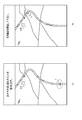
図4および図5は、表示部9に表示されるナビゲーション画面の一例を示す図である。図3のステップS3においてモード切替の意思表示がなされると、図4(a)に示されるように、通常のナビゲーション画面とともに「モード切替を受け付けました。処理を開始します。」というメッセージが表示される。ナビゲーション画面には、車両1を示す前向き三角形のアイコンと、走行中の道路などが示される。この状態から図3のステップS8までの手順が完了すると、図4(b)に示されるように、「切替区間をセットしました。」というメッセージとともに、道路上に切替区間を示す帯状のアイコン(図中、斜線のハッチングで示す)が表示される。なお図中、2つの切替区間が示されるが、これは2つ前の段落で述べた切替区間A,Bに対応する。
続いて図5(a)に示されるように、「おすすめ切り替えポイントを表示します。」というメッセージとともにモード切替推奨位置を示す矢印のシンボルアイコン200が表示される。図5(a)においては車両1から遠いほうの切替区間に矢印が向いているので、この切替区間の方が、より安全であることがわかる。この状態から引き継ぎ区間に接近すると、図5(b)の「引き継ぎを開始して下さい。」というメッセージが表示される。運転者はこのメッセージを認識した後に、周辺の目視やペダル類の踏み込みの引き継ぎなどの手順を開始する。なお以上のメッセージは、スピーカ10から拡声出力してももちろん良い。
図3に戻って説明を続ける。図3のステップS9、ステップS10の手順は、運転モードが自動運転モードから手動運転モードに切り替わるまで、例えば表示部9の表示の更新周期に応じた周期で繰り返される(ステップS11)。もちろん、例えばステップS1のマップデータの取得、ステップS2のトラフィックデータの取得は、他のステップにおける処理と同時並行的に実施されることもできる。各ステップに示される処理の順番は図3に限定されるものではない。
なお、図3のステップS6において渋滞の位置が特定されると、そのことがナビゲーション画面の表示と、切替区間の設定にも反映される。
なお、図3のステップS6において渋滞の位置が特定されると、そのことがナビゲーション画面の表示と、切替区間の設定にも反映される。
図6は、渋滞区間を含むナビゲーション画面の一例を示す図である。例えば、渋滞の位置が認識されると、そのことを示すインジケータ(渋滞インジケータ)が渋滞区間に沿って表示される。この渋滞は図5のシンボルアイコン200の付近に現れている。そこでモード切替支援装置6は、この渋滞区間を避けるように、手前の切替区間にモード切替推奨位置を設定し、その位置にシンボルアイコン200を移動させる。この画面を見た運転者は、渋滞を避けて手前でモード切替を実施すればよいことが分かる。
以上述べたようにこの実施形態では、自動運転モードでの走行中に、運転者から手動運転モードに切り替える意思表示がなされると、実際の切り替えに先立って計算部61bが、道路に沿った位置ごとの曲率半径を示す道路形状データ63cを計算する。その際、取得部61aにより取得されたマップデータ63aが利用される。また取得部61aは、トラフィックデータ63bを取得して計算部61bに渡す。計算部61bはこのトラフィックデータを解読して車両1周辺の有無、および位置を求める。そして計算部61bは、道路形状データ63cとトラフィックデータ63bに基づいてモード切替推奨位置を算出する。さらに設定部61dが、モード切替推奨位置を含む切替区間を設定する。そして通知部61cが、切替区間を含むナビゲーション画像を作成し、モード切替推奨位置を示すアイコンとともに表示部9に表示するようにしている。
このようにしたので、より安全かつ適切な切り替えポイントを含む切替区間が運転者に積極的に通知され、運転者は、カーブや渋滞などの障害の少ない位置において運転モードを切り替えられるようになる。つまり、運転者がモード切替を希望したとき、即、その近辺で実行に移すのではなく、例えばもっと先の、より安全な場所を探してアドバイスすることが可能になる。
またこの実施形態では、ディジタルマップデータ14aを用いて算出した道路形状や、公共放送などから取得したトラフィックデータに基づいて安全な位置を確認するようにした。これにより、車両1を含む数キロ四方の道路状況を把握することができ、レーダや画像センサを用いるのに比べて、モード切替推奨位置を、より広いレンジで探索することができる。つまりこの実施形態で開示した技術は「予め設定された切替区間のなかで安全な場所を探す」こともできるが、「安全な場所を探して、その周辺に切替区間を設定する」こともできる。
これらのことからこの実施形態によれば、運転モードを適切な位置で切り替えられるようになり、これにより安全性の向上を図った支援装置、支援方法およびプログラムを提供することができる。
なお、この発明は上記実施形態に限られるものではない。例えば、モード切替推奨位置は表示部9に表示するだけでなく、音声メッセージによって運転者に通知することも可能である。
図7に示されるように、車両1の現在位置からモード切替推奨位置までの距離を計算して「おすすめ切り替えポイントまであと500メートルです」という音声メッセージを流すようにしても良い。あるいは図8に示されるように、車両1の現在位置からモード切替推奨位置までの距離を現在の車速で除算して、モード切替推奨位置に至るまでに要する時間を計算し、「おすすめ切り替えポイントまであと40秒メートルです」という音声メッセージを流すようにしても良い。音声による通知は、例えば、ボリュームを大きくすれば運転者に覚醒効果をもたらすなどの、視覚的な通知とは異なる効果を期待できる。
また、切替区間のなかでも、モード切替の推奨度の値はある程度の広がりを持って分布していることが考えられる。そこで図9に示されるように、推奨度の分布を表示色に対応付けたカラーマップ画像を作成し、表示部9に表示するようにしてもよい。
図9は、切替区間を示す帯状アイコンを詳しく示す図である。図9に示されるように、モード切替の推奨の度合いを数値化した指標を色にマッピングし、推奨度の高い位置ほど濃い色(高密度のハッチングで示す)で表すようにしてもよい。このようにすれば運転者にさらに多くの情報を与えることができ、情報提供の面からのサポートをさらに充実させることができる。
また、モード切替支援装置6は組み込みの専用ハードウェア機器として提供することもできるし、既存の車載機器(例えばナビゲーションシステム50)に内蔵してしまっても良い。
さらに、ドライバカメラ7で撮像された運転者の映像データから運転者の状態を数値的に評価する技術と組み合わせれば、アナウンスをするか、しないかの判断も含め、さらに安全性を高めたシステムを提供できる可能性がある。
この発明の装置は、コンピュータとプログラムによっても実現でき、プログラムを記録媒体に記録することも、ネットワークを通して提供することも可能である。
また、以上の各装置及びそれらの装置部分は、それぞれハードウェア構成、またはハードウェア資源とソフトウェアとの組み合せ構成のいずれでも実施可能である。組み合せ構成のソフトウェアとしては、予めネットワークまたはコンピュータ読み取り可能な記録媒体からコンピュータにインストールされ、当該コンピュータのプロセッサに実行されることにより、各装置の機能を当該コンピュータに実現させるためのプログラムが用いられる。
また、以上の各装置及びそれらの装置部分は、それぞれハードウェア構成、またはハードウェア資源とソフトウェアとの組み合せ構成のいずれでも実施可能である。組み合せ構成のソフトウェアとしては、予めネットワークまたはコンピュータ読み取り可能な記録媒体からコンピュータにインストールされ、当該コンピュータのプロセッサに実行されることにより、各装置の機能を当該コンピュータに実現させるためのプログラムが用いられる。
コンピュータに関連して用いられる「プロセッサ」あるいは「ハードウェアプロセッサ」という用語は、例えばCPU、GPU(Graphics Processing Unit)、或いは、ASIC(Application Specific Integrated Circuit)、SPLD(Simple Programmable Logic Device)、CPLD(Complex Programmable Logic Device)、またはFPGA等の回路と理解され得る。
プロセッサは、メモリに記憶されたプログラムを読み出し実行することで、プログラムに基づく特有の機能を実現する。メモリに代えて、プロセッサの回路内にプログラムを直接組み込むよう構成することも可能である。このケースでは、プロセッサは回路内に組み込まれたプログラムを読み出し実行することでその機能を実現する。
このほか車両の種類、自動運転制御装置の機能、モード切替支援装置の機能と処理手順および処理内容等についても、この発明の要旨を逸脱しない範囲で種々変形して実施可能である。
要するにこの発明は、上記実施形態そのままに限定されるものではなく、実施段階ではその要旨を逸脱しない範囲で構成要素を変形して具体化できる。また、上記実施形態に開示されている複数の構成要素の適宜な組み合せにより種々の発明を形成できる。例えば、実施形態に示される全構成要素から幾つかの構成要素を削除してもよい。さらに、異なる実施形態に亘る構成要素を適宜組み合せてもよい。
上記の実施形態の一部又は全部は以下の付記のようにも記載され得るが、以下に限られるものではない。
(付記1)
車両の運転モードを手動運転モードと自動運転モードとの間で切り替えるモード切替を支援する支援装置であって、ハードウェアプロセッサと、メモリとを有し、
前記ハードウェアプロセッサは、
前記車両の周辺状況を示す周辺データを取得し、
前記取得された周辺データに基づいて、前記モード切替の推奨される位置であるモード切替推奨位置を計算し、
前記計算されたモード切替推奨位置の位置情報を前記メモリに記憶するように構成される、支援装置。
(付記1)
車両の運転モードを手動運転モードと自動運転モードとの間で切り替えるモード切替を支援する支援装置であって、ハードウェアプロセッサと、メモリとを有し、
前記ハードウェアプロセッサは、
前記車両の周辺状況を示す周辺データを取得し、
前記取得された周辺データに基づいて、前記モード切替の推奨される位置であるモード切替推奨位置を計算し、
前記計算されたモード切替推奨位置の位置情報を前記メモリに記憶するように構成される、支援装置。
(付記2)
車両の運転モードを手動運転モードと自動運転モードとの間で切り替えるモード切替を支援する支援方法であって、
少なくとも1つのハードウェアプロセッサを用いて、前記車両の周辺状況を示す周辺データを取得する過程と、
少なくとも1つのハードウェアプロセッサを用いて、前記取得された周辺データに基づいて、前記モード切替の推奨される位置であるモード切替推奨位置を計算する過程とを具備する、支援方法。
車両の運転モードを手動運転モードと自動運転モードとの間で切り替えるモード切替を支援する支援方法であって、
少なくとも1つのハードウェアプロセッサを用いて、前記車両の周辺状況を示す周辺データを取得する過程と、
少なくとも1つのハードウェアプロセッサを用いて、前記取得された周辺データに基づいて、前記モード切替の推奨される位置であるモード切替推奨位置を計算する過程とを具備する、支援方法。
Claims (13)
- 車両の運転モードを手動運転モードと自動運転モードとの間で切り替えるモード切替を支援する支援装置であって、
前記車両の周辺状況を示す周辺データを取得する取得部と、
前記取得された周辺データに基づいて、前記モード切替の推奨される位置であるモード切替推奨位置を計算する計算部とを具備する、支援装置。 - 前記取得部は、ディジタルマップデータを記憶するデータベースから、前記車両の周辺のマップデータを取得し、
前記計算部は、前記取得されたマップデータに基づいて、前記モード切替推奨位置を計算する、請求項1に記載の支援装置。 - 前記計算部は、
前記マップデータから前記車両の進行方向の道路の曲率を計算し、当該曲率を判定基準として前記モード切替推奨位置を計算する、請求項2に記載の支援装置。 - さらに、公共交通情報を受信する受信部を具備し、
前記計算部は、前記受信された公共交通情報に基づいて、前記モード切替推奨位置を計算する、請求項1に記載の支援装置。 - 前記計算部は、
前記公共交通情報から取得される前記車両の進行方向の渋滞状況を判定基準として前記モード切替推奨位置を計算する、請求項4に記載の支援装置。 - さらに、前記モード切替推奨位置を前記車両の運転者に通知する通知部を具備する、請求項1乃至5のいずれか1項に記載の支援装置。
- 前記通知部は、前記車両の周辺のマップ画像に前記モード切替推奨位置を重ねて表示器に表示する、請求項6に記載の支援装置。
- 前記通知部は、前記モード切替推奨位置に至るまでの時間を前記車両の運転者に音声で通知する、請求項6に記載の支援装置。
- さらに、前記モード切替推奨位置を含む前記モード切替のための切替区間を、前記車両の走行する道路に沿って設定する設定部を具備し、
前記通知部は、前記設定された切替区間を前記運転者に通知する、請求項6に記載の支援装置。 - 前記計算部は、前記モード切替の推奨の度合いを数値化した指標の前記切替区間における分布を計算し、
前記通知部は、前記指標の値を前記車両の周辺のマップ画像における表示色に対応付けてカラーマップ表示する、請求項9に記載の支援装置。 - 前記設定部は、操作者による前記モード切替の意思表示を受けると前記切替区間を設定する、請求項9に記載の支援装置。
- 車両の運転モードを手動運転モードと自動運転モードとの間で切り替えるモード切替をコンピュータにより支援する支援方法であって、
前記コンピュータが、前記車両の周辺状況を示す周辺データを取得する過程と、
前記コンピュータが、前記取得された周辺データに基づいて、前記モード切替の推奨される位置であるモード切替推奨位置を計算する過程とを具備する、支援方法。 - コンピュータを、請求項1乃至11のいずれか1項に記載の支援装置として機能させるためのプログラム。
Priority Applications (3)
| Application Number | Priority Date | Filing Date | Title |
|---|---|---|---|
| DE112017007184.4T DE112017007184T5 (de) | 2017-03-09 | 2017-09-13 | Unterstützungsvorrichtung, unterstützungsverfahren und programm |
| CN201780062802.7A CN109844456A (zh) | 2017-03-09 | 2017-09-13 | 辅助装置、辅助方法及程序 |
| US16/382,635 US20190232976A1 (en) | 2017-03-09 | 2019-04-12 | Assisting apparatus, assisting method, and program |
Applications Claiming Priority (2)
| Application Number | Priority Date | Filing Date | Title |
|---|---|---|---|
| JP2017-045143 | 2017-03-09 | ||
| JP2017045143A JP6648721B2 (ja) | 2017-03-09 | 2017-03-09 | 支援装置、支援方法およびプログラム |
Related Child Applications (1)
| Application Number | Title | Priority Date | Filing Date |
|---|---|---|---|
| US16/382,635 Continuation US20190232976A1 (en) | 2017-03-09 | 2019-04-12 | Assisting apparatus, assisting method, and program |
Publications (1)
| Publication Number | Publication Date |
|---|---|
| WO2018163473A1 true WO2018163473A1 (ja) | 2018-09-13 |
Family
ID=63447422
Family Applications (1)
| Application Number | Title | Priority Date | Filing Date |
|---|---|---|---|
| PCT/JP2017/033148 Ceased WO2018163473A1 (ja) | 2017-03-09 | 2017-09-13 | 支援装置、支援方法およびプログラム |
Country Status (5)
| Country | Link |
|---|---|
| US (1) | US20190232976A1 (ja) |
| JP (1) | JP6648721B2 (ja) |
| CN (1) | CN109844456A (ja) |
| DE (1) | DE112017007184T5 (ja) |
| WO (1) | WO2018163473A1 (ja) |
Families Citing this family (19)
| Publication number | Priority date | Publication date | Assignee | Title |
|---|---|---|---|---|
| KR101957796B1 (ko) * | 2017-09-05 | 2019-03-13 | 엘지전자 주식회사 | 차량에 구비된 차량 제어 장치 및 차량의 제어방법 |
| JP7086798B2 (ja) * | 2018-09-12 | 2022-06-20 | 本田技研工業株式会社 | 車両制御装置、車両制御方法、およびプログラム |
| CN110884500A (zh) * | 2019-10-31 | 2020-03-17 | 苏州智加科技有限公司 | 控制车辆的方法、装置、电子设备及存储介质 |
| GB2588972B (en) * | 2019-11-18 | 2024-10-02 | Jaguar Land Rover Ltd | A control system for a vehicle |
| JP7414605B2 (ja) * | 2020-03-23 | 2024-01-16 | 株式会社アイシン | 運転支援システム、運転支援プログラム |
| JP2021148685A (ja) * | 2020-03-23 | 2021-09-27 | 株式会社アイシン | 運転支援システム、運転支援プログラム |
| FR3109922B1 (fr) * | 2020-05-06 | 2022-06-17 | Renault Sas | Procédé de gestion d’un état d’un système de guidage d’un véhicule automobile. |
| JP7264121B2 (ja) | 2020-07-01 | 2023-04-25 | トヨタ自動車株式会社 | 車両の表示・音声出力制御システム |
| US11713979B2 (en) | 2020-08-27 | 2023-08-01 | Here Global B.V. | Method, apparatus, and computer program product for generating a transition variability index related to autonomous driving |
| US11687094B2 (en) | 2020-08-27 | 2023-06-27 | Here Global B.V. | Method, apparatus, and computer program product for organizing autonomous vehicles in an autonomous transition region |
| US11691643B2 (en) | 2020-08-27 | 2023-07-04 | Here Global B.V. | Method and apparatus to improve interaction models and user experience for autonomous driving in transition regions |
| JP7351283B2 (ja) | 2020-10-19 | 2023-09-27 | トヨタ自動車株式会社 | ドライバへの通知装置 |
| CN115112135B (zh) * | 2021-03-22 | 2025-04-08 | 滴图(北京)科技有限公司 | 交通信息展示的方法、装置、电子设备、介质及程序产品 |
| JP7530694B2 (ja) | 2021-03-26 | 2024-08-08 | パナソニックオートモーティブシステムズ株式会社 | 支援装置 |
| KR20220158184A (ko) * | 2021-05-21 | 2022-11-30 | 현대자동차주식회사 | 차량의 주행모드 제어 장치 및 그 방법 |
| CN117178308A (zh) * | 2021-08-06 | 2023-12-05 | 日立安斯泰莫株式会社 | 驾驶辅助装置及驾驶辅助方法 |
| FR3135540B1 (fr) * | 2022-05-10 | 2024-11-08 | Psa Automobiles Sa | Procédé de pilotage de fonctions d’assistance à la conduite d’un véhicule automobile lors du franchissement d’une bifurcation |
| DE102022003953B3 (de) * | 2022-10-25 | 2023-10-19 | Mercedes-Benz Group AG | Verfahren zum Betrieb eines Fahrzeuges |
| KR20260039295A (ko) * | 2024-09-13 | 2026-03-20 | 현대자동차주식회사 | 차량 및 그 제어 방법 |
Citations (3)
| Publication number | Priority date | Publication date | Assignee | Title |
|---|---|---|---|---|
| JP2016034782A (ja) * | 2014-08-01 | 2016-03-17 | トヨタ自動車株式会社 | 車両制御装置 |
| JP2016200931A (ja) * | 2015-04-09 | 2016-12-01 | 三菱電機株式会社 | 運転支援装置および運転支援方法 |
| JP2017032441A (ja) * | 2015-08-03 | 2017-02-09 | アイシン・エィ・ダブリュ株式会社 | 走行支援システム、走行支援方法及びコンピュータプログラム |
Family Cites Families (6)
| Publication number | Priority date | Publication date | Assignee | Title |
|---|---|---|---|---|
| JP4203857B2 (ja) * | 2004-03-01 | 2009-01-07 | 株式会社デンソー | 安全運転支援システム |
| JP6277741B2 (ja) | 2014-01-29 | 2018-02-14 | アイシン・エィ・ダブリュ株式会社 | ナビゲーション装置、ナビゲーション方法及びプログラム |
| JP6161553B2 (ja) * | 2014-02-25 | 2017-07-12 | アイシン・エィ・ダブリュ株式会社 | 自動運転支援システム、自動運転支援方法及びコンピュータプログラム |
| WO2015159341A1 (ja) * | 2014-04-14 | 2015-10-22 | 三菱電機株式会社 | 運転支援装置および運転支援方法 |
| JP6359986B2 (ja) * | 2015-02-13 | 2018-07-18 | トヨタ自動車株式会社 | 車両運転支援システム |
| TWI569671B (zh) * | 2015-06-30 | 2017-02-01 | 盟創科技股份有限公司 | 依據雲收集的連線品質資料的自動連線選擇方法與系統 |
-
2017
- 2017-03-09 JP JP2017045143A patent/JP6648721B2/ja not_active Expired - Fee Related
- 2017-09-13 WO PCT/JP2017/033148 patent/WO2018163473A1/ja not_active Ceased
- 2017-09-13 CN CN201780062802.7A patent/CN109844456A/zh active Pending
- 2017-09-13 DE DE112017007184.4T patent/DE112017007184T5/de not_active Withdrawn
-
2019
- 2019-04-12 US US16/382,635 patent/US20190232976A1/en not_active Abandoned
Patent Citations (3)
| Publication number | Priority date | Publication date | Assignee | Title |
|---|---|---|---|---|
| JP2016034782A (ja) * | 2014-08-01 | 2016-03-17 | トヨタ自動車株式会社 | 車両制御装置 |
| JP2016200931A (ja) * | 2015-04-09 | 2016-12-01 | 三菱電機株式会社 | 運転支援装置および運転支援方法 |
| JP2017032441A (ja) * | 2015-08-03 | 2017-02-09 | アイシン・エィ・ダブリュ株式会社 | 走行支援システム、走行支援方法及びコンピュータプログラム |
Also Published As
| Publication number | Publication date |
|---|---|
| JP2018146552A (ja) | 2018-09-20 |
| JP6648721B2 (ja) | 2020-02-14 |
| US20190232976A1 (en) | 2019-08-01 |
| CN109844456A (zh) | 2019-06-04 |
| DE112017007184T5 (de) | 2019-12-24 |
Similar Documents
| Publication | Publication Date | Title |
|---|---|---|
| JP6648721B2 (ja) | 支援装置、支援方法およびプログラム | |
| CN110920521B (zh) | 显示系统、显示方法及存储介质 | |
| WO2018163472A1 (ja) | モード切替制御装置、モード切替制御システム、モード切替制御方法およびプログラム | |
| US11548443B2 (en) | Display system, display method, and program for indicating a peripheral situation of a vehicle | |
| JP2023112082A (ja) | 車両用表示装置 | |
| US20230166754A1 (en) | Vehicle congestion determination device and vehicle display control device | |
| JP2019206339A (ja) | 走行制御装置及び車載システム | |
| US11105651B2 (en) | Display system, display control method, and storage medium for facilitating display of a road shape based on detection of a change | |
| US20190004513A1 (en) | Driving assistance control apparatus | |
| US20200377126A1 (en) | Information output control device and information output control method | |
| WO2016157883A1 (ja) | 走行制御装置及び走行制御方法 | |
| US11458841B2 (en) | Display control apparatus, display control method, and computer-readable storage medium storing program | |
| JP2017144933A (ja) | 車線変更支援装置 | |
| CN109416877B (zh) | 驾驶辅助方法、驾驶辅助装置、驾驶辅助系统 | |
| US10854172B2 (en) | Display system, display control method, and storage medium | |
| US10152835B2 (en) | Vehicle control device | |
| JP6468306B2 (ja) | 視認支援装置、方法およびプログラム | |
| JP2017211955A (ja) | 走行支援装置 | |
| WO2016157814A1 (ja) | 起動提案装置及び起動提案方法 | |
| US20230133086A1 (en) | Display control device, display control method, and recording medium | |
| US20240182058A1 (en) | Presentation control device, presentation control program, automated driving control device, and non-transitory tangible storage medium storing automated driving control program | |
| US10800431B2 (en) | Vehicle | |
| WO2018168123A1 (ja) | 制御装置、プログラム、支援装置および支援方法 | |
| JP2018169945A (ja) | 運転支援装置、運転支援方法及び運転支援プログラム | |
| JP2018139070A (ja) | 車両用表示制御装置 |
Legal Events
| Date | Code | Title | Description |
|---|---|---|---|
| 121 | Ep: the epo has been informed by wipo that ep was designated in this application |
Ref document number: 17900039 Country of ref document: EP Kind code of ref document: A1 |
|
| 122 | Ep: pct application non-entry in european phase |
Ref document number: 17900039 Country of ref document: EP Kind code of ref document: A1 |