WO2018163397A1 - 無停電電源装置および無停電電源装置の試験方法 - Google Patents
無停電電源装置および無停電電源装置の試験方法 Download PDFInfo
- Publication number
- WO2018163397A1 WO2018163397A1 PCT/JP2017/009663 JP2017009663W WO2018163397A1 WO 2018163397 A1 WO2018163397 A1 WO 2018163397A1 JP 2017009663 W JP2017009663 W JP 2017009663W WO 2018163397 A1 WO2018163397 A1 WO 2018163397A1
- Authority
- WO
- WIPO (PCT)
- Prior art keywords
- power supply
- command value
- voltage
- terminal
- inverter
- Prior art date
- Legal status (The legal status is an assumption and is not a legal conclusion. Google has not performed a legal analysis and makes no representation as to the accuracy of the status listed.)
- Ceased
Links
Images



Classifications
-
- H—ELECTRICITY
- H02—GENERATION; CONVERSION OR DISTRIBUTION OF ELECTRIC POWER
- H02J—ELECTRIC POWER NETWORKS; CIRCUIT ARRANGEMENTS OR SYSTEMS FOR SUPPLYING OR DISTRIBUTING ELECTRIC POWER; SYSTEMS FOR STORING ELECTRIC ENERGY
- H02J9/00—Circuit arrangements for emergency or stand-by power supply, e.g. for emergency lighting
- H02J9/04—Circuit arrangements for emergency or stand-by power supply, e.g. for emergency lighting in which the distribution system is disconnected from the normal source and connected to a standby source
- H02J9/06—Circuit arrangements for emergency or stand-by power supply, e.g. for emergency lighting in which the distribution system is disconnected from the normal source and connected to a standby source with automatic change-over, e.g. UPS systems
- H02J9/062—Circuit arrangements for emergency or stand-by power supply, e.g. for emergency lighting in which the distribution system is disconnected from the normal source and connected to a standby source with automatic change-over, e.g. UPS systems for AC powered loads
-
- G—PHYSICS
- G01—MEASURING; TESTING
- G01R—MEASURING ELECTRIC VARIABLES; MEASURING MAGNETIC VARIABLES
- G01R31/00—Arrangements for testing electric properties; Arrangements for locating electric faults; Arrangements for electrical testing characterised by what is being tested not provided for elsewhere
- G01R31/40—Testing power supplies
-
- H—ELECTRICITY
- H02—GENERATION; CONVERSION OR DISTRIBUTION OF ELECTRIC POWER
- H02J—ELECTRIC POWER NETWORKS; CIRCUIT ARRANGEMENTS OR SYSTEMS FOR SUPPLYING OR DISTRIBUTING ELECTRIC POWER; SYSTEMS FOR STORING ELECTRIC ENERGY
- H02J9/00—Circuit arrangements for emergency or stand-by power supply, e.g. for emergency lighting
- H02J9/04—Circuit arrangements for emergency or stand-by power supply, e.g. for emergency lighting in which the distribution system is disconnected from the normal source and connected to a standby source
- H02J9/06—Circuit arrangements for emergency or stand-by power supply, e.g. for emergency lighting in which the distribution system is disconnected from the normal source and connected to a standby source with automatic change-over, e.g. UPS systems
Definitions
- an uninterruptible power supply includes first and second terminals connected to an AC power supply, a third terminal connected to a power storage device, a fourth terminal, and a converter. , An inverter, first and second switches, and a control device.
- the converter is configured to convert AC power supplied from the AC power source via the first terminal into DC power.
- the inverter is configured to convert DC power generated by the converter or DC power of the power storage device into AC power.
- the first switch is connected between the output node of the inverter and the fourth terminal.
- the second switch is connected between the second terminal and the fourth terminal.
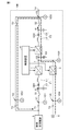
- the uninterruptible power supply 100 includes an input terminal T1, a bypass terminal T2, a battery terminal T3, and an output terminal T4.
- the input terminal T1 and the bypass terminal T2 are connected to the commercial AC power source 5.
- the output terminal T4 can be connected to a load (not shown). The load is driven by commercial frequency AC power supplied from the uninterruptible power supply 100.
- the voltage detector VD2 detects an instantaneous value of the AC voltage V2 at the bypass terminal T2 (that is, an AC voltage supplied from the commercial AC power supply 5), and gives a signal indicating the detected value to the control device 4.
- the voltage detector VD4 detects an instantaneous value of the AC voltage V4 at the output terminal T4, and gives a signal indicating the detected value to the control device 4.
- the voltage controller 12 generates the current command value I1 * so that the deviation V3R ⁇ V3 becomes zero.
- the voltage control unit 12 includes at least a proportional element (P: proportional element) and an integral element (I: integral element), for example, and performs a proportional integral operation with the deviation V3R-V3 as an input.
- the voltage control unit 12 generates a current command value I1 * as the calculation result.
- the subtractor 13 subtracts the current I1 (the detected value of the current detector CD1) from the current command value I1 * to obtain a deviation I1 * -I1 between I1 * and I1.
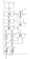
- FIG. 3 is a block diagram showing a configuration of a part related to the control of the inverter 2 in the control device 4.
- FIG. 3 shows the control of the inverter 2 during the electrical test.
- the control device 4 At the time of the electrical test, the control device 4 generates the current command value Ir based on the target values set in advance for the apparent power S [VA] and the power factor ⁇ that the uninterruptible power supply 100 should output.
- the control device 4 performs current feedback control of the inverter 2 so that the detected value of the current detector CD2 (that is, the output current I2 of the inverter 2) matches the generated current command value Ir.
- Idr Ir ⁇ cos ⁇ (1)
- Iqr Ir ⁇ sin ⁇ (2)
- the d-axis current command generation unit 20 When the current command value Ir and the power factor ⁇ are given, the d-axis current command generation unit 20 generates the d-axis current command value Idr using Equation (1). The generated d-axis current command value Idr is given to the subtracter 22.
- q-axis current command value 21 generates q-axis current command value Iqr using equation (2) when current command value Ir and power factor ⁇ are given. The generated q-axis current command value Iqr is given to the subtracter 23.
- the control device 4 determines that the d-axis component Id and the q-axis component Iq of the output current I2 of the inverter 2 are d
- the inverter 2 is subjected to current feedback control so as to coincide with the shaft current command value Idr and the q-axis current command value Iqr.
- the inverter 2 is controlled so that the detected value I2 (three-phase alternating current) of the current detector CD2 matches the current command value Ir. Therefore, the rated frequency of the alternating current is superimposed on the control gain of the feedback control.
- ⁇ c 314 rad / sec is superimposed on the response angular frequency of the control loop based on the frequency of the commercial AC power supply 5 (for example, 50 Hz). For this reason, the gain in the control loop needs to be high. Specifically, a gain that is at least one digit larger than ⁇ c (that is, 3140 rad / sec or more) is required.
- the synchronization control unit 30 detects the phase ⁇ of the AC power supply voltage V1 based on the detection value of the voltage detector VD1 (that is, the AC voltage V1 supplied from the commercial AC power supply 5).
- the synchronization control unit 30 is a PLL (Phase Locked Loop) circuit, for example, and controls the phase difference between the output voltage V5 of the inverter 2 and the AC power supply voltage V1 to be zero.
- PLL Phase Locked Loop
- the subtracter 22 subtracts the d-axis current Id from the d-axis current command value Idr generated by the d-axis current command generation unit 20 to obtain a deviation ⁇ Id between Idr and Id.
- the subtracter 23 subtracts the q-axis current Iq from the q-axis current command value Iqr generated by the q-axis current command generation unit 21 to obtain a deviation ⁇ Iq between Iqr and Iq.
- the current control unit 25 generates the q-axis voltage command value Vq * so that the deviation ⁇ Iq becomes zero. Specifically, the current control unit 25 performs a proportional integration operation with a predetermined gain on the deviation ⁇ Iq to obtain a control deviation, and generates a q-axis voltage command value Vq * corresponding to the control deviation.
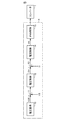
- FIG. 5 is a waveform diagram for explaining the control of the inverter 2 during the electrical test.
- FIG. 5 shows the relationship between the effective value of start command ST, voltage command Vo #, and the effective value of output current I2 of inverter 2.
- the control device 4 also controls the bidirectional chopper 3 based on the output signals of the voltage detectors VD3 and VD4.
- the bidirectional chopper 3 supplies DC power to the DC bus 7 so that the DC voltage V3 of the DC bus 7 becomes the reference voltage V3R.
Landscapes
- Business, Economics & Management (AREA)
- Emergency Management (AREA)
- Engineering & Computer Science (AREA)
- Power Engineering (AREA)
- Physics & Mathematics (AREA)
- General Physics & Mathematics (AREA)
- Inverter Devices (AREA)
- Stand-By Power Supply Arrangements (AREA)
Abstract
Description
無停電電源装置100の信頼性を保つために、無停電電源装置100の性能を確認するための電気試験が行なわれる。無停電電源装置100の電気試験を行なう場合、負荷もしくは摸擬負荷を使用せずに、無停電電源装置100を運転する。具体的には、図1に示すように、出力端子T4に負荷を接続しない状態で、制御装置4はコンバータ1およびインバータ2を運転させる。図1において、電気試験時の電力の流れを破線矢印を用いて示す。
Iqr=Ir×sinφ …(2)
d軸電流指令生成部20は、電流指令値Irおよび力率φが与えられると、式(1)を用いてd軸電流指令値Idrを生成する。生成されたd軸電流指令値Idrは減算器22に与えられる。q軸電流指令値21は、電流指令値Irおよび力率φが与えられると、式(2)を用いてq軸電流指令値Iqrを生成する。生成されたq軸電流指令値Iqrは減算器23に与えられる。
Claims (6)
- 無停電電源装置であって、
交流電源に接続される第1および第2の端子と、
蓄電装置に接続される第3の端子と、
第4の端子と、
前記交流電源から前記第1の端子を介して供給される交流電力を直流電力に変換するように構成されたコンバータと、
前記コンバータによって生成された直流電力または前記蓄電装置の直流電力を交流電力に変換するように構成されたインバータと、
前記インバータの出力ノードと前記第4の端子との間に接続される第1のスイッチと、
前記第2の端子と前記第4の端子との間に接続される第2のスイッチと、
前記第4の端子に負荷が接続されていない状態で前記無停電電源装置の電気試験を行なう場合において、前記第1および第2のスイッチをオンさせるとともに、前記インバータの出力電流を電流指令値に従って制御するように構成された制御装置とを備え、
前記制御装置は、
前記電流指令値を所定の力率を用いて座標変換したd軸電流指令値およびq軸電流指令値と、前記出力電流を前記交流電源の電圧の位相を用いて座標変換したd軸電流値およびq軸電流値との偏差に基づいて電圧指令値を生成し、かつ、
前記電圧指令値に基づいて前記インバータの制御信号を生成するように構成される、無停電電源装置。 - 前記制御装置は、さらに、前記無停電電源装置の電気試験を行なう場合において前記インバータを起動するときには、前記電圧指令値の実効値を0から所定の電圧値まで上昇させるとともに、前記制御信号の周波数を0から前記交流電源の周波数まで上昇させるように構成される、請求項1に記載の無停電電源装置。
- 前記制御装置は、前記第4の端子に接続が予定される前記負荷の力率を用いて前記電流指令値の座標変換を実行するように構成される、請求項1または2に記載の無停電電源装置。
- 無停電電源装置の試験方法であって、
前記無停電電源装置は、
交流電源に接続される第1および第2の端子と、
蓄電装置に接続される第3の端子と、
第4の端子と、
前記交流電源から前記第1の端子を介して供給される交流電力を直流電力に変換するように構成されたコンバータと、
前記コンバータによって生成された直流電力または前記蓄電装置の直流電力を交流電力に変換するように構成されたインバータと、
前記インバータの出力ノードと前記第4の端子との間に接続される第1のスイッチと、
前記第2の端子と前記第4の端子との間に接続される第2のスイッチとを含み、
前記第4の端子に前記負荷が接続されていない状態で前記無停電電源装置の電気試験を行なう場合において、前記試験方法は、
前記第1および第2のスイッチをオンするステップと、
電流指令値を所定の力率を用いて座標変換したd軸電流指令値およびq軸電流指令値と、前記インバータの出力電流を前記交流電源の電圧の位相を用いて座標変換したd軸電流値およびq軸電流値との偏差に基づいて、電圧指令値を生成するステップと、
前記電圧指令値に基づいて前記インバータの制御信号を生成するステップとを備える、無停電電源装置の試験方法。 - 前記試験方法は、さらに、前記無停電電源装置の電気試験を行なう場合において前記インバータを起動するときには、前記電圧指令値の実効値を0から所定の電圧値まで上昇させるとともに、前記制御信号の周波数を0から前記交流電源の周波数まで上昇させるステップを備える、請求項4に記載の無停電電源装置の試験方法。
- 前記電圧指令値を生成するステップでは、前記第4の端子に接続が予定される前記負荷の力率を用いて前記電流指令値の座標変換を実行する、請求項4または5に記載の無停電電源装置の試験方法。
Priority Applications (5)
| Application Number | Priority Date | Filing Date | Title |
|---|---|---|---|
| CN201780088164.6A CN110383624B (zh) | 2017-03-10 | 2017-03-10 | 不间断电源装置以及不间断电源装置的试验方法 |
| PCT/JP2017/009663 WO2018163397A1 (ja) | 2017-03-10 | 2017-03-10 | 無停電電源装置および無停電電源装置の試験方法 |
| JP2019504261A JP6744477B2 (ja) | 2017-03-10 | 2017-03-10 | 無停電電源装置および無停電電源装置の試験方法 |
| KR1020197028019A KR102281416B1 (ko) | 2017-03-10 | 2017-03-10 | 무정전 전원 장치, 및 무정전 전원 장치의 시험 방법 |
| TW106120893A TWI661653B (zh) | 2017-03-10 | 2017-06-22 | 不斷電電源裝置及不斷電電源裝置的試驗方法 |
Applications Claiming Priority (1)
| Application Number | Priority Date | Filing Date | Title |
|---|---|---|---|
| PCT/JP2017/009663 WO2018163397A1 (ja) | 2017-03-10 | 2017-03-10 | 無停電電源装置および無停電電源装置の試験方法 |
Publications (1)
| Publication Number | Publication Date |
|---|---|
| WO2018163397A1 true WO2018163397A1 (ja) | 2018-09-13 |
Family
ID=63447468
Family Applications (1)
| Application Number | Title | Priority Date | Filing Date |
|---|---|---|---|
| PCT/JP2017/009663 Ceased WO2018163397A1 (ja) | 2017-03-10 | 2017-03-10 | 無停電電源装置および無停電電源装置の試験方法 |
Country Status (5)
| Country | Link |
|---|---|
| JP (1) | JP6744477B2 (ja) |
| KR (1) | KR102281416B1 (ja) |
| CN (1) | CN110383624B (ja) |
| TW (1) | TWI661653B (ja) |
| WO (1) | WO2018163397A1 (ja) |
Cited By (4)
| Publication number | Priority date | Publication date | Assignee | Title |
|---|---|---|---|---|
| JPWO2020021591A1 (ja) * | 2018-07-23 | 2020-07-30 | 東芝三菱電機産業システム株式会社 | 無停電電源装置 |
| CN113049981A (zh) * | 2019-07-30 | 2021-06-29 | 深圳市泛海三江电子股份有限公司 | 一种用于测试消防电源的主电备电转换性能的测试方法 |
| JP7073590B1 (ja) * | 2021-01-29 | 2022-05-23 | 東芝三菱電機産業システム株式会社 | 無停電電源装置 |
| US11539237B2 (en) | 2020-06-11 | 2022-12-27 | Fuji Electric Co., Ltd. | Uninterruptible power supply system and uninterruptible power supply |
Families Citing this family (4)
| Publication number | Priority date | Publication date | Assignee | Title |
|---|---|---|---|---|
| CN110829576B (zh) * | 2019-11-06 | 2021-04-09 | 漳州科华技术有限责任公司 | 不间断电源输入异常检测方法、系统及终端设备 |
| US12113395B2 (en) * | 2020-06-15 | 2024-10-08 | Tmeic Corporation | Power converter |
| JP7200398B1 (ja) * | 2021-04-16 | 2023-01-06 | 東芝三菱電機産業システム株式会社 | 無停電電源装置 |
| CN117008002A (zh) * | 2023-07-06 | 2023-11-07 | 华能鹤岗发电有限公司 | 一种ups在线监测装置及方法 |
Citations (2)
| Publication number | Priority date | Publication date | Assignee | Title |
|---|---|---|---|---|
| JP2003180035A (ja) * | 1995-06-27 | 2003-06-27 | Mitsubishi Electric Corp | インバータの同期切り換え回路 |
| WO2017006427A1 (ja) * | 2015-07-07 | 2017-01-12 | 東芝三菱電機産業システム株式会社 | 無停電電源装置 |
Family Cites Families (11)
| Publication number | Priority date | Publication date | Assignee | Title |
|---|---|---|---|---|
| JPH0833232A (ja) * | 1994-07-22 | 1996-02-02 | Meidensha Corp | Ups試験用電源装置 |
| WO2007144959A1 (ja) * | 2006-06-16 | 2007-12-21 | Mitsubishi Electric Corporation | 電力変換器の制御装置 |
| JP4422164B2 (ja) * | 2007-03-28 | 2010-02-24 | 株式会社日立製作所 | 電力変換装置及び電力変換方法 |
| KR100830351B1 (ko) * | 2007-09-12 | 2008-05-20 | 국제통신공업 주식회사 | 아이지비티 유피에스 시스템 |
| JP2009232541A (ja) | 2008-03-21 | 2009-10-08 | Toshiba Mitsubishi-Electric Industrial System Corp | 無停電電源装置及びその試験方法 |
| KR101539397B1 (ko) * | 2013-11-25 | 2015-08-07 | 한국전기연구원 | 직류 및 교류 겸용 다기능 시험을 위한 시뮬레이터 |
| CN106471704B (zh) * | 2014-06-26 | 2019-10-01 | 东芝三菱电机产业系统株式会社 | 不间断电源装置 |
| WO2015198448A1 (ja) * | 2014-06-26 | 2015-12-30 | 東芝三菱電機産業システム株式会社 | 無停電電源装置 |
| EP3240139A4 (en) * | 2014-12-25 | 2018-08-15 | Toshiba Mitsubishi-Electric Industrial Systems Corporation | Uninterruptible power supply device |
| JP6243553B2 (ja) * | 2014-12-25 | 2017-12-06 | 東芝三菱電機産業システム株式会社 | 無停電電源システム |
| KR101727063B1 (ko) | 2016-06-22 | 2017-04-17 | 네오피스 주식회사 | 비상발전기의 정속 운전을 위한 에너지 저장 장치의 제어 방법 |
-
2017
- 2017-03-10 WO PCT/JP2017/009663 patent/WO2018163397A1/ja not_active Ceased
- 2017-03-10 KR KR1020197028019A patent/KR102281416B1/ko active Active
- 2017-03-10 CN CN201780088164.6A patent/CN110383624B/zh active Active
- 2017-03-10 JP JP2019504261A patent/JP6744477B2/ja active Active
- 2017-06-22 TW TW106120893A patent/TWI661653B/zh active
Patent Citations (2)
| Publication number | Priority date | Publication date | Assignee | Title |
|---|---|---|---|---|
| JP2003180035A (ja) * | 1995-06-27 | 2003-06-27 | Mitsubishi Electric Corp | インバータの同期切り換え回路 |
| WO2017006427A1 (ja) * | 2015-07-07 | 2017-01-12 | 東芝三菱電機産業システム株式会社 | 無停電電源装置 |
Cited By (7)
| Publication number | Priority date | Publication date | Assignee | Title |
|---|---|---|---|---|
| JPWO2020021591A1 (ja) * | 2018-07-23 | 2020-07-30 | 東芝三菱電機産業システム株式会社 | 無停電電源装置 |
| CN113049981A (zh) * | 2019-07-30 | 2021-06-29 | 深圳市泛海三江电子股份有限公司 | 一种用于测试消防电源的主电备电转换性能的测试方法 |
| CN113049981B (zh) * | 2019-07-30 | 2024-05-31 | 深圳市高新投三江电子股份有限公司 | 一种消防电源自动化测试方法 |
| US11539237B2 (en) | 2020-06-11 | 2022-12-27 | Fuji Electric Co., Ltd. | Uninterruptible power supply system and uninterruptible power supply |
| JP7073590B1 (ja) * | 2021-01-29 | 2022-05-23 | 東芝三菱電機産業システム株式会社 | 無停電電源装置 |
| WO2022162876A1 (ja) * | 2021-01-29 | 2022-08-04 | 東芝三菱電機産業システム株式会社 | 無停電電源装置 |
| US12155264B2 (en) | 2021-01-29 | 2024-11-26 | Tmeic Corporation | Uninterruptible power supply apparatus |
Also Published As
| Publication number | Publication date |
|---|---|
| KR102281416B1 (ko) | 2021-07-23 |
| TWI661653B (zh) | 2019-06-01 |
| TW201834355A (zh) | 2018-09-16 |
| JPWO2018163397A1 (ja) | 2020-01-09 |
| JP6744477B2 (ja) | 2020-08-19 |
| KR20190117736A (ko) | 2019-10-16 |
| CN110383624A (zh) | 2019-10-25 |
| CN110383624B (zh) | 2022-08-05 |
Similar Documents
| Publication | Publication Date | Title |
|---|---|---|
| JP6744477B2 (ja) | 無停電電源装置および無停電電源装置の試験方法 | |
| US10615636B2 (en) | Uninterruptible power supply | |
| JP6097864B1 (ja) | 自立運転機能を有する系統連系用電力変換装置、及びその起動制御方法 | |
| JP5184153B2 (ja) | 単相電圧型交直変換装置及び単相電圧型交直変換回路の制御方法 | |
| CN107852023B (zh) | 不间断电源装置 | |
| JPWO2010143514A1 (ja) | 負荷駆動システムの制御装置 | |
| WO2017217013A1 (ja) | 電力変換装置 | |
| CN114600337B (zh) | 不间断电源装置 | |
| US12206248B2 (en) | Grid-connected control method and system for grid-forming converter without grid-side voltage sensor | |
| US10826383B2 (en) | Power conversion device | |
| JP4664836B2 (ja) | 三相電圧型交直変換装置 | |
| Somkun et al. | Fast DC bus voltage control of single-phase PWM rectifiers using a ripple voltage estimator | |
| JP7613552B2 (ja) | インバータ、並列インバータシステム、及び、インバータの制御方法 | |
| JP4777913B2 (ja) | 三相電圧型交直変換装置 | |
| JP5616411B2 (ja) | 単相電圧型交直変換装置 | |
| JP2017016556A (ja) | 自励式電力変換装置 | |
| JP2013106368A (ja) | 電力変換装置 | |
| JP5616412B2 (ja) | 単相電圧型交直変換装置 | |
| JP5408079B2 (ja) | コンバータの制御方法及びコンバータの制御装置 | |
| Paitandi et al. | Grid-Connected Active Front End Converter with Automatic Phase Sequence Detection and Corrective Control | |
| Lee et al. | Applied nonlinear control with adaptive backstepping technique for a three-phase AC/DC boost converter | |
| JP2014072983A (ja) | 単相電圧型交直変換装置 | |
| JP2005341720A (ja) | コンバータの制御方法及びコンバータの制御装置 | |
| JP2014072982A (ja) | 単相電圧型交直変換装置 | |
| JP2015133765A (ja) | 電力変換装置 |
Legal Events
| Date | Code | Title | Description |
|---|---|---|---|
| 121 | Ep: the epo has been informed by wipo that ep was designated in this application |
Ref document number: 17899361 Country of ref document: EP Kind code of ref document: A1 |
|
| ENP | Entry into the national phase |
Ref document number: 2019504261 Country of ref document: JP Kind code of ref document: A |
|
| NENP | Non-entry into the national phase |
Ref country code: DE |
|
| ENP | Entry into the national phase |
Ref document number: 20197028019 Country of ref document: KR Kind code of ref document: A |
|
| 122 | Ep: pct application non-entry in european phase |
Ref document number: 17899361 Country of ref document: EP Kind code of ref document: A1 |