WO2018158989A1 - ラチェット装置 - Google Patents
ラチェット装置 Download PDFInfo
- Publication number
- WO2018158989A1 WO2018158989A1 PCT/JP2017/033700 JP2017033700W WO2018158989A1 WO 2018158989 A1 WO2018158989 A1 WO 2018158989A1 JP 2017033700 W JP2017033700 W JP 2017033700W WO 2018158989 A1 WO2018158989 A1 WO 2018158989A1
- Authority
- WO
- WIPO (PCT)
- Prior art keywords
- input
- roller
- load
- movable piece
- contact
- Prior art date
- Legal status (The legal status is an assumption and is not a legal conclusion. Google has not performed a legal analysis and makes no representation as to the accuracy of the status listed.)
- Ceased
Links
Images









Classifications
-
- A—HUMAN NECESSITIES
- A47—FURNITURE; DOMESTIC ARTICLES OR APPLIANCES; COFFEE MILLS; SPICE MILLS; SUCTION CLEANERS IN GENERAL
- A47C—CHAIRS; SOFAS; BEDS
- A47C1/00—Chairs adapted for special purposes
- A47C1/02—Reclining or easy chairs
- A47C1/022—Reclining or easy chairs having independently-adjustable supporting parts
- A47C1/024—Reclining or easy chairs having independently-adjustable supporting parts the parts, being the back-rest, or the back-rest and seat unit, having adjustable inclination
-
- B—PERFORMING OPERATIONS; TRANSPORTING
- B60—VEHICLES IN GENERAL
- B60N—SEATS SPECIALLY ADAPTED FOR VEHICLES; VEHICLE PASSENGER ACCOMMODATION NOT OTHERWISE PROVIDED FOR
- B60N2/00—Seats specially adapted for vehicles; Arrangement or mounting of seats in vehicles
- B60N2/02—Seats specially adapted for vehicles; Arrangement or mounting of seats in vehicles the seat or part thereof being movable, e.g. adjustable
- B60N2/04—Seats specially adapted for vehicles; Arrangement or mounting of seats in vehicles the seat or part thereof being movable, e.g. adjustable the whole seat being movable
- B60N2/16—Seats specially adapted for vehicles; Arrangement or mounting of seats in vehicles the seat or part thereof being movable, e.g. adjustable the whole seat being movable height-adjustable
-
- B—PERFORMING OPERATIONS; TRANSPORTING
- B60—VEHICLES IN GENERAL
- B60N—SEATS SPECIALLY ADAPTED FOR VEHICLES; VEHICLE PASSENGER ACCOMMODATION NOT OTHERWISE PROVIDED FOR
- B60N2/00—Seats specially adapted for vehicles; Arrangement or mounting of seats in vehicles
- B60N2/90—Details or parts not otherwise provided for
-
- F—MECHANICAL ENGINEERING; LIGHTING; HEATING; WEAPONS; BLASTING
- F16—ENGINEERING ELEMENTS AND UNITS; GENERAL MEASURES FOR PRODUCING AND MAINTAINING EFFECTIVE FUNCTIONING OF MACHINES OR INSTALLATIONS; THERMAL INSULATION IN GENERAL
- F16D—COUPLINGS FOR TRANSMITTING ROTATION; CLUTCHES; BRAKES
- F16D41/00—Freewheels or freewheel clutches
- F16D41/06—Freewheels or freewheel clutches with intermediate wedging coupling members between an inner and an outer surface
- F16D41/08—Freewheels or freewheel clutches with intermediate wedging coupling members between an inner and an outer surface with provision for altering the freewheeling action
-
- F—MECHANICAL ENGINEERING; LIGHTING; HEATING; WEAPONS; BLASTING
- F16—ENGINEERING ELEMENTS AND UNITS; GENERAL MEASURES FOR PRODUCING AND MAINTAINING EFFECTIVE FUNCTIONING OF MACHINES OR INSTALLATIONS; THERMAL INSULATION IN GENERAL
- F16D—COUPLINGS FOR TRANSMITTING ROTATION; CLUTCHES; BRAKES
- F16D63/00—Brakes not otherwise provided for; Brakes combining more than one of the types of groups F16D49/00 - F16D61/00
Definitions
- the present invention relates to a ratchet device used for a vehicle seat height adjustment mechanism or the like.
- the output shaft rotates by operating a lever provided on the input side that swings up and down.
- the weight of the seat and the occupant applies a force to the seat to lower the seat.
- a clutch unit including a brake device configured so that the output shaft does not rotate and a ratchet device for operating the brake device is used.
- Patent Document 1 includes an output ring for operating a brake device, and an operation input member disposed radially inside the output ring, and a wedge-shaped space between the output ring and the operation input member.
- a ratchet device having a roller disposed thereon is disclosed. In this ratchet device, when the operation input member is rotated, the operation input member and the output ring are rotated together by the roller being sandwiched between the operation input member and the output ring.
- the present invention has been made in view of the above background, and an object thereof is to suppress damage to the ratchet device when an unexpected load is applied to the ratchet device.
- the present invention aims to suppress the weight increase of the ratchet device.
- an object of the present invention is to suppress a load on the movable piece by suppressing an increase in the surface pressure of the movable piece used in the ratchet device.
- the ratchet device of the present invention for achieving the above-described object includes a rotatable output member having a cylindrical load input surface on the inner periphery or outer periphery, and a load opposed to the load input surface in the radial direction of the load input surface.
- An operation input member having a working surface that is non-parallel to the input surface and capable of swinging operation, a movable piece disposed between the load input surface and the working surface, and the movable piece between the load input surface and the working surface.
- the operation input member has a protruding portion that protrudes from the action surface so as to approach the load input surface.
- the ratchet device has a predetermined value or more on the operation input member.
- the projecting portion includes a step surface extending from the working surface so as to approach the load input surface, a top surface extending in the rotation direction of the output member from an end portion of the step surface close to the load input surface, and a step surface. And a corner portion connecting the top surfaces.
- the protrusion can have a shape that contacts the movable piece at the corner.
- the protrusion amount of the protrusion from the working surface can be reduced to suppress an increase in the weight of the ratchet device.
- the protruding portion may have a shape that contacts the movable piece on the step surface. In this case, the surface pressure between the movable piece and the step surface when the movable piece is pushed can be reduced.
- the protruding portion may have a shape that contacts the movable piece at a position closer to the action surface than the center of the movable piece in the radial direction. In this case, the protrusion amount of the protrusion from the working surface can be reduced to suppress an increase in the weight of the ratchet device.
- the protruding portion may have a shape that contacts the movable piece at the same position as the center of the movable piece in the radial direction or at a position closer to the load input surface than the center of the movable piece. In this case, when the protruding portion comes into contact with the movable piece and is pressed, it is difficult to press the movable piece against the load input surface, so that an increase in the load on the output member or the operation input member can be suppressed.
- the movable piece is preferably a roller. According to this configuration, the operation of the ratchet device can be smoothed, and the surface pressure applied to the movable piece can be reduced.
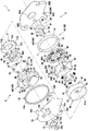
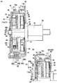
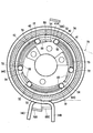
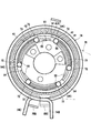
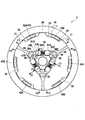
- FIG. 4 is a ZZ sectional view (a) of FIG. 3 and a YY sectional view (b) of FIG. 3 of the clutch unit. It is the figure which looked at the input side rotation member from the output side. It is the figure which looked at the friction member from the input side. It is the perspective view which looked at the clutch unit from the cover member side.
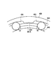
- FIG. 10 is a diagram (a) to (c) of a protrusion according to a modification. It is the elements on larger scale of the ratchet apparatus concerning a modification.
- a clutch unit 1 according to an embodiment including the brake device of the present invention is a known height adjuster for adjusting the height of a seat cushion S1 of a vehicle seat S as an example of a vehicle seat. Applies to the mechanism.
- a lever 75 is attached to the operation input member 50, and the height of the seat cushion S ⁇ b> 1 can be adjusted by driving a height adjustment mechanism by rotating an output side rotation member 30 described later by operating the lever 75. is there.
- the lever 75 when the lever 75 is raised from the neutral position N, the seat cushion S1 is raised by a predetermined amount, and when the lever 75 is lowered from the neutral position N, the seat cushion S1 is lowered by a predetermined amount.
- the lever 75 is returned from the upper or lower position to the neutral position N, the output side rotating member 30 is not rotated.
- the clutch unit 1 is configured by housing each member in a housing 100.
- the housing 100 is configured by a combination of the outer ring 10, the mounting plate 85, and the cover member 60.
- the left side in FIG. 2 where the cover member 60 and the operation input member 50 are arranged is referred to as “input side”
- the right side in FIG. 2 where the output side rotation member 30 is arranged is referred to as “output side”. Called.
- the clutch unit 1 is provided on the input side, and transmits and blocks the input torque generated by the swinging operation of the operation input member 50.
- the clutch unit 1 is provided on the output side, and the input torque from the ratchet device 2 is output to the output side rotating member. 30 and a brake device 3 for cutting off the reverse input torque from the output gear 35.
- the ratchet device 2 includes an operation input member 50, a regulating member 71, a roller 72 as an example of a movable piece, a first return spring 73, A second return spring 74, a lever 75, and a retaining plate 77 are provided.
- the brake device 3 includes an outer ring 10, a brake shoe 20, an output side rotating member 30, an input side rotating member 40, a roller 81, a spring 82, and a friction member 90 as an example of a spacing member. And a washer 76.
- the input side rotating member 40 is an output member of the ratchet device 2 and an input member of the brake device 3, and can be referred to as any part of the ratchet device 2 and the brake device 3.
- the outer ring 10 is formed of a ring having a predetermined thickness, and includes a cylindrical inner peripheral surface 11, a cylindrical outer peripheral surface 12, and a pair of side surfaces 13 and 14 that connect the inner peripheral surface 11 and the outer peripheral surface 12. Yes.
- the pair of side surfaces 13 and 14 are located on the radially outer side of the outer ring 10 with respect to the inner peripheral surface 11, and are flat surfaces orthogonal to the axis of the inner peripheral surface 11.
- the radial direction and the circumferential direction are based on the inner circumferential surface 11 of the outer ring 10.
- the mounting plate 85 that constitutes a part of the housing 100 together with the outer ring 10 is a sheet metal member for supporting the brake device 3.
- the attachment plate 85 is formed with two attachment holes 85B for attaching the brake device 3 to the frame of the seat cushion S1.
- the mounting plate 85 has a through hole 85 ⁇ / b> A through which the output side rotation member 30 is passed.
- a spring holding portion 85C extending toward the input side is provided at the lower portion of the mounting plate 85. Since the outer ring 10 is fixed to the attachment plate 85, the clutch unit 1 can be attached to various devices.
- the outer ring 10 is formed by punching a thick plate by press forming, and is welded to the input side surface of the mounting plate 85 at the outer peripheral edge 14B of the output side surface 14 by laser welding.
- the brake shoes 20 are members that generate a braking force between the outer ring 10 and three brake shoes 20 are arranged on the inner side in the radial direction of the outer ring 10 at equal intervals in the circumferential direction.
- the brake shoe 20 includes a main body portion 20A that extends in the circumferential direction, and a protruding portion 20B and a protrusion 20C that protrude outward in the radial direction on the outer periphery of the main body portion 20A.
- Each protrusion 20B is provided at each circumferential end of the outer periphery of the main body 20A.
- Each protrusion 20 ⁇ / b> B has a brake surface 21 that faces the inner peripheral surface 11 of the outer ring 10 and can contact the inner peripheral surface 11 at the distal end on the radially outer side.
- the brake surface 21 has substantially the same curvature as the inner peripheral surface 11 of the outer ring 10, and as shown in FIG. 3, in the brake surface 21, in the vicinity of the outer side in the circumferential direction (the outer circumferential direction on the basis of each brake shoe 20). ) Is arranged so as to contact the inner peripheral surface 11 of the outer ring 10. Thereby, when the brake shoe 20 is urged radially outward, the contact portion in the vicinity of the outer periphery in the circumferential direction of the brake surface 21 is pressed against the inner peripheral surface 11 of the outer ring 10.
- the protrusion 20C is provided at the circumferential center of the outer periphery of the main body 20A.
- a support surface 26 capable of abutting on the inner peripheral surface 11 of the outer ring 10 is provided at the radially outer end of the protrusion 20C.
- the support surface 26 is provided at the center between the pair of brake surfaces 21.
- the support surface 26 has substantially the same curvature as the inner peripheral surface 11 of the outer ring 10, and has a cylindrical surface shape along the inner peripheral surface 11 of the outer ring 10.
- the support surface 26 is separated from the inner peripheral surface 11 of the outer ring 10 in a state where no load is applied to the brake shoe 20 and the output-side rotating member 30.
- the brake shoe 20 includes a cylindrical outer peripheral surface having a smaller diameter than the brake surface 21 between one of the pair of brake surfaces 21 and the support surface 26 and between the other of the pair of brake surfaces 21 and the support surface 26. 22. Further, the brake shoe 20 has an inner side surface 23 facing inward in the radial direction. And the brake shoe 20 has the end surface 24 which connects the both ends of the inner surface 23, and the edge part 21E of the two brake surfaces 21 in the edge part of the circumferential direction. Further, the brake shoe 20 has a rotational force input surface 25 facing the circumferential direction at a step between the brake surface 21 and the outer peripheral surface 22.
- Each of the inner side surfaces 23 has three surfaces that are opposed to a later-described facing surface 36 of the output side rotating member 30.
- the inner side surface 23 includes a first contact surface 23A, a first inclined surface 23B disposed on the counterclockwise side of the drawing with respect to the first contact surface 23A, It has the 1st inclined surface 23C arrange
- 23 A of 1st contact surfaces can contact with the roller 81, and the direction along the straight line L1 (refer FIG. 3) which connected both the edge parts 21E of the circumferential direction of a pair of brake surface 21 (refer FIG. 4 (FIG. 4).
- the plane is parallel to the connection direction indicated by the arrow in a).
- the first inclined surfaces 23B and 23C are flat surfaces that are inclined with respect to the first contact surface 23A so as to approach the facing surface 36 (the lower side in the figure) as they move away from the first contact surface 23A between them. .
- the output side rotation member 30 includes a shaft-like action part 31, a flange 32 formed on the output side of the action part 31, and projects from the action part 31 to the input side.
- the support shaft portion 33 is coaxial and has a small diameter, and an output gear 35 formed so as to protrude to the output side of the flange 32.
- the output side rotation member 30 is disposed on the radially inner side of each brake shoe 20. The output gear 35 protrudes to the output side through the through hole 85 ⁇ / b> A of the mounting plate 85.
- the action portion 31 has a facing surface 36 facing the inner side surface 23 of the brake shoe 20 and a curved surface portion 38 on the outer periphery thereof.
- Three opposing surfaces 36 are provided on the outer periphery of the action portion 31 corresponding to the inner surface 23 of each brake shoe 20.
- a pair of rollers 81 is disposed between each inner surface 23 and each opposing surface 36.
- the curved surface portion 38 is a portion that connects the facing surfaces 36 corresponding to the brake shoes 20, and there is a total of 3 one pair between the facing surfaces 36 adjacent to each other in the circumferential direction of the outer periphery of the action portion 31.
- the curved surface portion 38 is formed as a curved surface having a circular arc shape in sectional view with the rotation center of the output side rotation member 30 as the center.
- the facing surface 36 includes second contact surfaces 36 ⁇ / b> A and 36 ⁇ / b> B arranged one by one on both ends of the facing surface 36 in the circumferential direction, and each second contact on both ends.
- a connecting surface portion 36C that connects the surfaces 36A and 36B.
- the second contact surface 36A is disposed on the counterclockwise side in the drawing with respect to the connection surface portion 36C
- the second contact surface 36B is disposed on the clockwise side in the drawing with respect to the connection surface portion 36C.
- the second contact surfaces 36A and 36B are capable of contacting the roller 81 in a state where no load is applied to the brake shoe 20, and are inclined with respect to the first contact surface 23A and outside the inclined portion 361. And a curved surface portion 362 arranged continuously.
- the inclined portion 361 is inclined so as to approach the first contact surface 23A (the upper side in the drawing) as it moves away from the reference plane PL orthogonal to the first contact surface 23A through the center 11C of the inner peripheral surface 11 of the outer ring 10. .
- the curved surface portion 362 is a convex shape that is convex toward the brake shoe 20 when viewed along the axial direction of the output-side rotating member 30, and the curved surface has a curvature radius that decreases as the distance from the reference plane PL increases. Yes.
- the facing surface 36 includes a portion non-parallel to the first contact surface 23 ⁇ / b> A that is a part of the inner surface 23 of the brake shoe 20.
- connection surface portion 36C has a flat surface portion 36D provided at the center portion in the circumferential direction and inclined portions 36E provided at both end portions in the circumferential direction.
- the plane portion 36D is a plane orthogonal to the reference plane PL in a state where no load is input to the brake shoe 20 and the output side rotating member 30. Accordingly, the flat portion 36D is arranged in parallel with the first contact surface 23A in a state where no load is input to the brake shoe 20 and the output-side rotating member 30.
- the inclined portion 36E is inclined so as to be away from the first contact surface 23A from the end of the flat surface portion 36D toward the inner end in the circumferential direction of the second contact surfaces 36A and 36B as the distance from the reference plane PL increases. Yes.
- the opposing surface 36 is a recessed portion formed by the end portion on the inner side in the circumferential direction of the second contact surfaces 36A and 36B and the inclined portion 36E at the connection portion between the second contact surfaces 36A and 36B and the connection surface portion 36C. 36F.
- the distance between the first contact surface 23A and the connection surface portion 36C (plane portion 36D) is smaller than the diameter of the roller 81. But the space
- a pair of rollers 81 is disposed between the inner surface 23 of each brake shoe 20 and each opposing surface 36 of the output side rotating member 30.
- the roller 81A is the one disposed on the counterclockwise side in FIG. 3 and the one disposed on the clockwise side in FIG. Let it be a roller 81B.
- the roller 81A is in contact with the first contact surface 23A and the second contact surface 36A, and the roller 81B is in contact with the first contact surface 23A.
- roller 81 is disposed between the inner surface 23 and the facing surface 36, so that in the brake device 3, a load is transmitted between the inner surface 23 and the facing surface 36 via the roller 81.
- the springs 82 are compression coil springs, and are provided one by one between the pair of rollers 81A and 81B.
- the spring 82 urges the pair of rollers 81 ⁇ / b> A and 81 ⁇ / b> B toward the narrow side of the space formed between the inner surface 23 and the facing surface 36 by separating them in the circumferential direction.
- the inclination angles and positions of the contact surfaces 36A and 36B are adjusted.
- the input side rotating member 40 shown in FIG. 2 can rotate around the axes of the outer ring 10 and the output side rotating member 30, receives the rotational output of the ratchet device 2, and hits the brake shoe 20 of the brake device 3 in the circumferential direction. It is a member that can contact and give rotational torque to the brake shoe 20.
- the input-side rotating member 40 includes a cylindrical pressure-receiving ring portion 41, a plurality of engagement legs 42 that protrude from the pressure-receiving ring portion 41 toward the output side, and a radially inner side from the vicinity of the axial center of the pressure-receiving ring portion 41.
- the inner peripheral surface 41A of the pressure receiving ring portion 41 is an example of a load input surface and has a circular cross section.
- Three pairs of engagement legs 42 are provided at equal intervals corresponding to each brake shoe 20, and are arranged between the inner peripheral surface 11 of the outer ring 10 and the outer peripheral surface 22 of the brake shoe 20.
- the pair of engaging legs 42 includes an engaging leg 42A disposed between the protrusion 20C and the anticlockwise protrusion 20B of FIG. 3, and the protrusion 20C and the clockwise protrusion of FIG.
- the engaging leg 42B is disposed between the portions 20B.
- the sizes of the protrusion 20B, the protrusion 20C and the engagement legs 42A and 42B are set so as to allow play in the rotation direction (circumferential direction).
- Each engagement leg 42A, 42B is formed in substantially the same shape.
- the play in the rotation direction (circumferential direction) of the brake shoe 20 with respect to the input side rotation member 40 (engaging legs 42A and 42B) is, for example, 4 °.
- the holding portion 44 is a portion that suppresses the roller 81 from falling off between the inner surface 23 and the opposed surface 36, and is disposed between the rollers 81 in the circumferential direction. Specifically, a pair of rollers 81A and 81B corresponding to each brake shoe 20 are disposed adjacent to both sides in the circumferential direction, and a total of three are provided.
- the holding portion 44 is disposed away from the roller 81 in a state where no load is input to the input side rotating member 40 and the output side rotating member 30. More specifically, the holding unit 44 is a roller 81 adjacent to the upstream side in the rotation direction of the rotation torque in a state where the rotation torque in the normal use range is input to the output side rotation member 30. It arrange
- the holding unit 44 rotates the input-side rotating member 40 in the same rotational direction as the rotational torque of the output-side rotating member 30 from the state where the rotating torque is input to the output-side rotating member 30, so At the time of contact in the direction, the roller 81 adjacent to the downstream side in the rotation direction, in this embodiment, is arranged so as not to contact the roller 81A.
- the holding portion 44 contacts the roller 81 adjacent to the downstream side in the rotation direction of the holding portion 44 in a state where the input-side rotating member 40 is in contact with the brake shoe 20 in the circumferential direction to rotate the brake shoe 20.
- the holding portion 44 may be in non-contact with the roller 81 in a state where the brake shoe 20 is rotated by the input side rotation member 40.
- the through hole 45 allows the action part 31 of the output side rotation member 30 to be inserted, and on its inner periphery, three circumferential surface parts 46 along the curved surface part 38 of the action part 31, and It has 3 convex surface parts 47 which are arrange
- Each convex surface portion 47 includes a top portion 47A that protrudes inward in the radial direction, a release surface 47B that is adjacent to the top portion 47A on the clockwise side in FIG. 6 (counterclockwise side in FIG. 3), and a counterclockwise direction in FIG. And a flank 47C adjacent to the rotation side (clockwise side in FIG. 3).
- the release surface 47B is arranged to face the facing surface 36, and the input of the clockwise rotational torque in FIG. 3 to the output side rotating member 30 due to the weight of the occupant sitting on the vehicle seat S is input.
- the side rotation member 40 is rotated in the rotation direction opposite to the rotation torque (counterclockwise direction in FIG. 3) and brought into contact with the brake shoe 20 in the circumferential direction, the counter surface 36 rotates in the opposite direction substantially simultaneously. It has a shape that can transmit rotational torque in the direction.
- the clearance surface 47C has a release surface 47B whose angle with respect to the flat surface portion 36D (see FIG. 4) of the opposing surface 36 in a state in which no load is input from the outside to the input side rotation member 40 and the output side rotation member 30. It is formed larger than the size of the angle with respect to the flat portion 36D.
- the flank 47C has a shape that does not come into contact with the flat surface portion 36D when the input side rotation member 40 is rotated in the clockwise direction in FIG. 3 and brought into contact with the brake shoe 20 in the circumferential direction.
- flank 47C has the same angle with respect to the flat surface portion 36D as the angle with respect to the flat surface portion 36D of the release surface 47B, and the release surface 47B in the clockwise direction of the input side rotation member 40 in FIG. It may have the same function.
- the friction member 90 is a member that generates an auxiliary braking force for suppressing the sudden start of the operation of the output-side rotating member 30 at the moment when the braking force of the braking device 3 is broken.
- the friction member 90 includes a first ring portion 91, a second ring portion 92, a connecting portion 93 that connects the first ring portion 91 and the second ring portion 92, and a second ring portion.
- the plurality of protruding portions 94 as an example of the pressure contact portion and the engaging portion that protrude from 92, and the interval holding portion 95 that protrudes from the first ring portion 91 are included.
- the interval holding portion 95 is a portion that is arranged between the brake shoes 20 in the circumferential direction and holds an interval in the rotation direction of the brake shoes 20, and matches the number of brake shoes 20. A plurality, three in this case, are provided.
- Each spacing holding portion 95 is disposed in a substantially triangular space surrounded by two brake shoes 20 adjacent to each other in the circumferential direction and the holding portion 44. That is, since the space
- the 1st ring part 91 is a part which connects the some space
- the first ring portion 91 has a fitting hole 91A having the same shape as the cross-sectional contour of the action portion 31, and is relative to the output-side rotating member 30 by fitting the action portion 31 and the fitting hole 91A. It is designed not to rotate.
- the second ring portion 92 is a portion that holds the plurality of protruding portions 94 so as to be integrally rotatable, and is disposed on the radially outer side than the first ring portion 91.
- the protruding portion 94 protrudes on the radially outer side of the outer ring 10 and on the input side in the axial direction of the output side rotating member 30.
- the protruding portion 94 is a pressure contact surface 94 ⁇ / b> A in which a radially outer surface is pressed against the inner peripheral surface 11 of the outer ring 10.
- the diameter of the pressure contact surface 94 ⁇ / b> A is slightly larger than the inner diameter of the inner peripheral surface 11.
- the outer peripheral surface 92 ⁇ / b> A other than the protruding portion 94 of the second ring portion 92 has a diameter smaller than the inner diameter of the inner peripheral surface 11 of the outer ring 10. For this reason, when the friction member 90 is combined with the outer ring 10, only the pressure contact surface 94 ⁇ / b> A is in pressure contact with the inner peripheral surface 11, and the outer peripheral surface 92 ⁇ / b> A is separated from the inner peripheral surface 11.
- the protrusion 94 is disposed between a pair of protrusions 20 ⁇ / b> B in one brake shoe 20. More specifically, the protrusion 94 is a first protrusion 94X disposed between the protrusion 20C of the brake shoe 20 and the protrusion 20B disposed on the clockwise side of FIG. 3 with respect to the protrusion 20C. And a protrusion 20C of the brake shoe 20 and a second protrusion 94Y disposed between the protrusion 20C and the protrusion 20B disposed counterclockwise in FIG.
- the first protrusion 94X has a first engagement surface 94B at the clockwise end in FIG. 7, and the second protrusion 94Y has a counterclockwise end in FIG.
- the portion has a second engagement surface 94C.
- the first engaging surface 94B and the second engaging surface 94C are both input to the rotational force of the protruding portion 20B of the brake shoe 20 when no load is input to the input-side rotating member 40. Separated from the surface 25.
- both the pressure contact portion and the engagement portion are realized by the protruding portion 94. That is, the engagement portion rotates integrally with the pressure contact portion, and the pressure contact portion and the engagement portion are arranged at the same position in the circumferential direction.
- the connecting portion 93 includes meandering connecting portions 93 ⁇ / b> A and 93 ⁇ / b> B having a meandering shape and a plate-like connecting portion 93 ⁇ / b> C.
- the plate-shaped connecting portion 93C is disposed between the connecting portion 93A adjacent to the connecting portion 93B in the clockwise direction.
- the connecting portions 93A and 93B have a narrow shape that can be bent and deformed, and the connecting portion 93C has a wide plate shape that is less likely to bend and deform than the connecting portions 93A and 93B.
- the 1st ring part 91 and the 2nd ring part 92 are not formed in the whole plate shape, but are connected with the 1st ring part 91 by connecting with a plurality of connecting parts 93.
- the connecting portion 93 can be bent somewhat. For this reason, it is easy for the friction member 90 to achieve both the function of generating the auxiliary braking force and the function of balancing the circumferential positions of the plurality of brake shoes 20.
- the friction member 90 consists of resin, for example. If the friction member 90 is made of resin, a complicated shape can be easily formed, and since the sound is hardly generated when sliding with the inner peripheral surface 11, the operation of the brake device 3 can be made quiet.
- the friction member 90 is disposed on the output side of the brake shoe 20.
- the friction member 90 is press-fitted inside the outer ring 10, and each protrusion 94 is disposed between the protrusion 20 ⁇ / b> B and the protrusion 20 ⁇ / b> C of the brake shoe 20.
- Each protrusion 94 is formed in substantially the same range as the engaging legs 42A and 42B in the rotation direction. For this reason, the play in the rotation direction (circumferential direction) of the brake shoe 20 with respect to each protrusion 94 is, for example, 4 °.
- the play in the rotation direction (circumferential direction) of the brake shoe 20 with respect to the gap holding portion 95 of the friction member 90 is larger than 0 ° and smaller than 3.4 °.
- the play in the circumferential direction of the brake shoe 20 with respect to the friction member 90 is smaller than the play in the circumferential direction of the brake shoe 20 with respect to the input-side rotating member 40.
- the washer 76 has a hole 76A having a diameter slightly smaller than the outer diameter of the support shaft portion 33 of the output side rotating member 30, and the hole 76A is press-fitted into the support shaft portion 33 (see FIG. 5).
- the outer diameter of the washer 76 is larger than a support hole 64 of the cover member 60 described later, so that the output-side rotating member 30 cannot be pulled out to the output side by the washer 76.
- the operation input member 50 engages with the lever 75 and can swing with the lever 75 within a predetermined angle range from the neutral position.
- the operation input member 50 is a member that transmits the rotational torque from the lever 75 to the input side rotation member 40 via the roller 72 by moving integrally with the input side rotation member 40 via the roller 72. Therefore, the operation input member 50 includes a cam plate portion 51 and two lever engaging portions 52 as attachment portions of the lever 75 that extend from the cam plate portion 51 to the input side.
- the cam plate portion 51 has three arcuate small-diameter portions 53 on the outer peripheral surface and continuously extends in the circumferential direction from the small-diameter portion 53, and the diameter gradually increases from the small-diameter portion 53. And a larger working surface 55.
- the cam plate portion 51 has three projecting portions 54 that project from the working surface 55 so as to approach the inner peripheral surface 41A of the pressure receiving ring portion 41 that is a load input surface.
- the small-diameter portions 53 and the protruding portions 54 are alternately arranged in the circumferential direction, and the action surfaces 55 are arranged in a total of six locations between the protruding portions 54 and the small-diameter portions 53 in the circumferential direction.
- the radial direction and the circumferential direction are used with reference to the load input surface, here, the inner peripheral surface 41A.
- the action surface 55 faces the inner peripheral surface 41A in the radial direction. Moreover, the action surface 55 is non-parallel to the inner peripheral surface 41A, and is formed such that the distance from the inner peripheral surface 41A becomes narrower as the projection portion 54 is approached. In addition, a hole 56 through which the output side rotation member 30 passes is formed at the center of the cam plate portion 51.
- a roller 72 is disposed between each action surface 55 and the inner peripheral surface 41A of the pressure receiving ring portion 41. As will be understood from the description of the operation described later, the roller 72 engages and disengages the operation input member 50 and the input side rotation member 40 to transmit and block input torque.
- a total of six rollers 72 are arranged corresponding to each working surface 55. As shown in FIG. 5A, the working surface 55 is longer in the direction than half the axial length of the roller 72, and includes the central portion (see the center line C ⁇ b> 1) in the axial direction of the roller 72. It is arranged so as to be able to abut. Accordingly, the working surface 55 can stably hold the roller 72 between the pressure receiving ring portion 41.
- the protrusion 54 includes a step surface 54A extending from the working surface 55 so as to approach the inner peripheral surface 41A, and an input side rotating member from an end portion of the step surface 54A close to the inner peripheral surface 41A.
- 40 has a top surface 54B extending in the rotation direction, and a corner portion 54C connecting the step surface 54A and the top surface 54B.
- the stepped surface 54A is inclined with respect to the working surface 55 so as to move away from the roller 72 as it goes outward in the radial direction.
- the protruding amount of the protruding portion 54 is relatively small, and the protruding portion 54 has a shape in contact with the roller 72 at the corner portion 54C.
- the protruding portion 54 has a shape that contacts the movable piece at a position closer to the working surface 55 than the center 72A of the roller 72 in the radial direction.
- the corner portion 54C includes a shape having a roundness necessary for manufacturing.
- the regulating member 71 is a member that regulates the position of the roller 72, and one side of the operation input member 50 in the rotational axis direction with respect to the plurality of rollers 72.
- the side wall portion 71A disposed on the output side and the three regulating portions 71B extending from the outer peripheral edge of the side wall portion 71A toward the input side are configured.
- the restricting portion 71 ⁇ / b> B is longer than the length of the roller 72 in the axial direction, and its tip is press-fitted into the fitting hole 66 of the cover member 60.
- the regulating member 71 has a hole 71 ⁇ / b> C through which the output side rotating member 30 passes at the center.
- the restricting portion 71B is disposed at the same rotational position on the radially outer side of the protruding portion 54 when the lever 75 is not operated, and the working surface 55 and the pressure receiving ring portion 41, the movement of the roller 72 between 41 in the circumferential direction is restricted.
- a first return spring 73 made of a compression coil spring is disposed with an initial load applied between two rollers 72 disposed between the adjacent restricting portions 71B. For this reason, each roller 72 is in contact with the restricting portion 71B during the non-operation of FIG.
- the restricting portion 71 ⁇ / b> B is disposed so as to include a position where the center of the roller 72 is located in the radial direction of the outer ring 10, and is in contact with the most protruding portion of the roller 72 in the circumferential direction. Thereby, the control part 71B can support the roller 72 stably.
- FIG. 9A the roller 72 is shown in contact with the restricting portion 71B. However, the roller 72 is sandwiched between the action surface 55 and the inner peripheral surface 41A, so that the restricting portion 71B It may be slightly separated.
- the lever engaging portion 52 protrudes from the cam plate portion 51 in the axial direction of the output side rotating member 30 with an arcuate cross section.
- Each lever engaging portion 52 has a screw hole 52A on an end face in the axial direction.
- Each lever engaging portion 52 has a sector shape when viewed from the axial direction, and has a side surface 52B extending in the radial direction (see FIG. 9A).
- the cover member 60 includes a disk-shaped side wall portion 61 and an outer peripheral portion 62 extending from the outer peripheral edge of the side wall portion 61 to the output side in the axial direction of the output side rotation member.
- the side wall portion 61 has a direction that intersects the axial direction of the output-side rotating member 30, and in the present embodiment, has a direction that is orthogonal to the axial direction.
- the outer peripheral portion 62 includes a small diameter portion 62A extending from the side wall portion 61, a flange portion 62B extending in the radial direction from the output side end portion of the small diameter portion 62A, and the flange portion 62B.
- a large-diameter portion 62C extending from the outer peripheral edge to the output side.
- the large diameter portion 62 ⁇ / b> C is fixed to the outer ring 10 by being fitted to the outside of the outer peripheral surface 12 of the outer ring 10.
- the outer peripheral portion 62 is disposed between the first return spring 73 and the second return spring 74, thereby suppressing interference between the first return spring 73 and the second return spring 74.
- the side wall 61 has a circular support hole 64 at its center, two arc holes 65 extending in an arc shape around the support hole 64, and a position radially outside the arc hole 65. Then, three fitting holes 66 arranged at equal intervals in the circumferential direction and a convex portion 67 projecting into the housing 100 are formed.
- the support hole 64 is a portion that fits with the support shaft portion 33 of the output side rotation member 30 and pivotally supports the output side rotation member 30.
- the arc hole 65 is provided corresponding to the lever engaging portion 52 of the operation input member 50, and is formed in an arc shape in a wider angle range than the lever engaging portion 52.
- the convex portion 67 includes a first convex portion 67 ⁇ / b> A that protrudes toward the operation input member 50 and a second convex portion that protrudes toward the pressure-receiving ring portion 41 of the input-side rotating member 40. 67B.
- the convex portion 67 is slidable with the components in the casing 100 and suppresses play in the axial direction of the components in the casing 100.
- the fitting holes 66 are three through holes provided corresponding to the three restricting portions 71B of the restricting member 71 (see also FIG. 2), so that the restricting member 71 does not rotate relative to the cover member 60.
- the cover member 60 is fitted. Since the regulating member 71 and the cover member 60 are fitted at a plurality of locations, the regulation member 71 can be firmly regulated to rotate.
- the large-diameter portion 62 ⁇ / b> C of the outer peripheral portion 62 is fitted to the outside of the outer peripheral surface 12 of the outer ring 10. Then, the large-diameter portion 62C of the cover member 60 is pressed while the side wall portion 61 is pushed to the output side in the axial direction of the output-side rotating member 30 with a predetermined load to bring the convex portion 67 into contact with the component (input-side rotating member 40) in the housing. Is fixed to the outer ring 10 by laser welding.
- the first convex portion 67A suppresses the operation input member 50 from playing in the axial direction between the side wall portion 71A of the regulating member 71 and the side wall portion 61 of the cover member 60. For this reason, when press-fitting the restricting portion 71B into the fitting hole 66, the restricting portion 71B is press-fitted with a load such that the first convex portion 67A and the operation input member 50 are in light contact with each other.
- the second return spring 74 has a coil portion 74A, a first arm 74B extending radially outward from one end of the coil portion 74A, and a radially outer side extending from the other end of the coil portion 74A.
- This is a torsion spring having a second arm 74C.
- the coil portion 74 ⁇ / b> A is disposed on the radially outer side of the outer peripheral portion 62 of the cover member 60.
- the first return spring 73 and the second return spring 74 are on one plane perpendicular to the rotation axis of the operation input member 50.
- the first return spring 73 and the second return spring 74 do not generate a force that squeezes the operation input member 50, and the operation input member 50 can be smoothly returned to the neutral position.
- the lever 75 is output from the main body 75A extending left and right in FIG. 2, the spring engaging portion 75B extending from the lower end of the main body 75A to the output side, and the upper end of the main body 75A. And a cover portion 75C extending to the side.
- the main body portion 75A is positioned on the input side with respect to the coil portion 74A of the second return spring 74.
- the spring engaging portion 75B is engaged with the first arm 74B and the second arm 74C of the second return spring 74.
- the main body portion 75A has a circular through hole 75D through which the support shaft portion 33 of the output side rotation member 30 passes and two engagement holes 75E with which the two lever engagement portions 52 of the operation input member 50 are engaged.
- the engagement hole 75E has an edge 75F extending in the radial direction.
- the lever engaging portion 52 is press-fitted into the engaging hole 75E so that the edge portion 75F of the engaging hole 75E clamps the lever engaging portion 52 in the rotation direction of the operation input member 50. That is, this press-fitting causes the edge 75F and the side surface 52B of the lever engaging portion 52 to be in constant pressure contact with each other, so that the lever 75 does not play in the rotational direction with respect to the operation input member 50. Thereby, the operational feeling of the lever 75 can be improved.
- the spring engaging portion 75B has the same size as the spring holding portion 85C of the mounting plate 85 in the circumferential direction. And the spring engaging part 75B is arrange
- the first arm 74B and the second arm 74C of the second return spring 74 are engaged with the spring holding portion 85C of the mounting plate 85 and the spring engaging portion 75B of the lever 75 in the rotational direction.
- the first arm 74B and the second arm 74C are urged in a direction approaching each other, and sandwich the spring holding portion 85C and the spring engagement portion 75B. That is, the lever 75 is always biased toward the neutral position shown in FIG. 8 by the second return spring 74.
- the retaining plate 77 has two holes 77A corresponding to the screw holes 52A and a center hole 77B corresponding to the through hole 75D of the lever 75.
- the center hole 77B suppresses the washer 76 (see FIG. 2) from interfering with the retaining plate 77.
- the retaining plate 77 is fixed to the operation input member 50 by two bolts 78 passing through the holes 77A and fastened to the screw holes 52A. Thereby, it is suppressed that the lever 75 comes off from the operation input member 50.
- the roller 72 In the neutral position shown in FIG. 9A, the roller 72 is positioned between the inner peripheral surface 41A of the input side rotating member 40 and the operation surface 55 of the operation input member 50, but there is a slight gap between them. Yes, they are not sandwiched between them.
- the roller 72 is urged toward the restricting portion 71B by a first return spring 73 made of a compression coil spring. Thereby, the first return spring 73 biases the posture of the operation input member 50 to the neutral position.
- the second return spring 74 holds the spring engaging portion 75B and the spring holding portion 85C between the first arm 74B and the second arm 74C. With this clamping force, the position of the spring engaging portion 75B in the rotational direction is aligned with the spring holding portion 85C. That is, the second return spring 74 biases the posture of the lever 75 and the operation input member 50 to the neutral position.
- the spring engaging portion 75B of the lever 75 moves the second arm 74C in the clockwise direction against the urging force of the second return spring 74.
- the second arm 74C biases the spring engagement portion 75B in the counterclockwise direction.
- the lever 75 When the load applied to the input side rotation member 40 is more than a predetermined value, such as when an object is caught by the mechanism that raises or lowers the seat, the lever 75 is lowered from the neutral position to slightly swing the operation input member 50 clockwise.
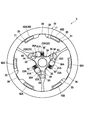
- the pressure receiving ring portion 41 cannot be rotated only by the roller 72 being sandwiched between the working surface 55 and the inner peripheral surface 41A, and the operation input is performed with the pressure receiving ring portion 41 stopped. Only member 50 rotates clockwise. If the operation input member 50 is swung clockwise with an input torque equal to or greater than a predetermined value, the pressure-receiving ring portion 41 is bent radially outward at a portion in contact with the roller 72.
- the protruding portion 54 of the operation input member 50 comes into contact with the roller 72.
- the corner portion 54C of the protruding portion 54 contacts the roller 72 at a position closer to the working surface 55 than the center 72A of the roller 72 (see FIG. 9B).
- the load applied to the pressure-receiving ring portion 41 may be more than a predetermined value, such as an extremely heavy occupant sitting on the vehicle seat S.
- the description is omitted because it is the same as the case of swinging downward, except that the rotation direction is opposite.
- the output side rotation member 30 when the output side rotation member 30 is given a clockwise rotation torque in the drawing, that is, a rotation torque in the normal use range, by the weight of the passenger sitting on the vehicle seat S, the output side rotation member 30 slightly rotates clockwise, and the distance between the second contact surface 36A (one of the pair of second contact surfaces 36A and 36B of the one opposing surface 36 on the counterclockwise side) and the first contact surface 23A is narrow.
- the pressures of the roller 81A one of the pair of rollers 81 corresponding to one brake shoe 20 on the counterclockwise side
- the second contact surface 36A, and the first contact surface 23A are increased.
- the roller 81A When the roller 81A is in contact with the first inclined surface 23B in a state where no load is input to the output-side rotating member 30, the roller 81A rolls between the facing surface 36 and the inner side surface 23, When it moves to a position in contact with the first contact surface 23A, the pressure between the second contact surface 36A and the first contact surface 23A is sufficiently increased and stops against the opposing surface 36 and the inner surface 23.
- the second contact surface 36B one of the pair of second contact surfaces 36A, 36B of the one opposing surface 36 on the clockwise side
- the roller 81B (one of the pair of rollers 81 corresponding to one brake shoe 20 on the clockwise side) is strongly sandwiched between the second contact surface 36B and the first contact surface 23A. You can roll without being caught.
- the brake shoe 20 has the pair of brake surfaces 21 pressed against the inner peripheral surface 11 of the outer ring 10 with the force F3.
- a frictional force is generated between the brake surface 21 and the inner peripheral surface 11, so that the output side rotating member 30 does not rotate. That is, a braking force that prevents the vehicle seat S from being lowered is generated.
- the support surface 26 is separated from the inner peripheral surface 11 of the outer ring 10.
- the roller 81B is slightly separated from the holding portion 44 adjacent in the rotation direction of the output side rotation member 30, that is, the clockwise direction. Therefore, not only the roller 81A is sandwiched between the facing surface 36 and the inner side surface 23, but also the roller 81B can be maintained between the facing surface 36 and the inner side surface 23 by the biasing force of the spring 82. Thereby, even if the brake shoe 20 is rotated in any direction thereafter, the frictional force between the brake shoe 20 and the outer ring 10 can be maintained, so that an unexpected release of the braking force can be suppressed.
- the input side rotating member 40 when the input side rotating member 40 is rotated clockwise by operating the lever 75 in order to lower the height of the vehicle seat S from the brake state of FIG. 14, as shown in FIG. 16, the input side rotating member Forty engagement legs 42B abut on the rotational force input surface 25 of the brake shoe 20 in the circumferential direction at the clockwise end. At this time, the holding portion 44 is not in contact with the roller 81A adjacent to the downstream side in the rotation direction (clockwise direction side). When the input side rotation member 40 is further rotated clockwise, the engaging leg 42B pushes the rotational force input surface 25 with the force F21, and the brake shoe 20 starts to rotate clockwise.
- the brake shoe 20 and the output side rotating member 30 are relatively opposite to the case where the output side rotating member 30 is rotated clockwise in FIG. To work. That is, as shown in FIG. 17, the brake shoe 20 is slightly rotated clockwise, and the first contact surface 23A and the second contact surface 36B (the pair of second contact surfaces 36A and 36B of the one opposing surface 36 have a timepiece By reducing the distance between the one on the rotation side), the roller 81B (one of the rollers 81 corresponding to one brake shoe 20 on the clockwise side), the first contact surface 23A and the second contact surface 36B. Increased pressure.
- roller 81B rolls between the opposing surface 36 and the inner side surface 23 and moves to a position in contact with the first contact surface 23A.
- the pressure between 36 ⁇ / b> B and the first contact surface 23 ⁇ / b> A is sufficiently increased and stops against the facing surface 36 and the inner surface 23.
- the roller 81A (one of the pair of rollers 81 corresponding to one brake shoe 20 on the counterclockwise side) is located between the first contact surface 23A and the second contact surface 36A. You can roll while the pressure of the water gradually decreases.
- the holding unit 44 is in contact with the roller 81 ⁇ / b> A adjacent on the downstream side in the rotation direction and presses the roller 81 ⁇ / b> A in the clockwise direction.
- the gap between the protrusion 20B of the brake shoe 20 and the second protrusion 94Y of the friction member 90, that is, the protrusion 20B is the second protrusion.
- the friction member 90 rotates clockwise so as to be dragged by the brake shoe 20.
- the friction member 90 is in pressure contact with the inner peripheral surface 11 of the outer ring 10 at the protruding portion 94, and thus provides resistance (auxiliary brake force) to the rotation of the brake shoe 20.
- the holding portion 44 is not in contact with the roller 81A, so that the roller 81B is sandwiched with sufficient force between the first contact surface 23A and the second contact surface 36B. Further, since the roller 81A that has generated the braking force is not pushed by the holding portion 44, the braking force is prevented from being unexpectedly weakened.
- the brake shoe 20 is deformed so that the main body portion 20 ⁇ / b> A bends radially outward, and the support surface 26 contacts the inner peripheral surface 11 of the outer ring 10.
- the support surface 26 of the brake shoe 20 is supported by the outer ring 10, and further deformation is suppressed, so that the load on the brake shoe 20 can be reduced.
- the roller 81 pushes the inner side surface 23 of the brake shoe 20 so that the brake surface 21 is moved.
- the brake shoe 20 does not rotate by being pressed against the inner peripheral surface 11 of the outer ring 10.
- the roller 81 is formed between the inner surface 23 and the facing surface 36 of the output side rotation member 30. Since one of the rollers 81 is always sandwiched between the inner surface 23 and the facing surface 36, that is, in contact with these, since it is biased to the narrow side of the space, it can be maintained.
- the brake force can be generated by each of the plurality of brake shoes 20 arranged in the circumferential direction, it is possible to suppress an increase in the size of the brake device 3 in the axial direction. As a result, the size in the axial direction can be reduced, and stable operation can be performed.
- the frictional force of the friction member 90 assists the brake shoe 20. Acts as a braking force. Therefore, even when the brake force of the brake shoe 20 is reduced when the lever 75 is used to lower the vehicle seat S, the output-side rotating member 30 is prevented from rotating suddenly by the auxiliary brake force. can do. And since the protrusion part 94 provided in the outer peripheral part of the friction member 90 and the brake shoe 20 are engaging, the engaging part which engages with the part which generate
- the second ring portion 92 is close to the inner peripheral surface 11 of the outer ring 10, it is possible to efficiently generate a frictional force and transmit it to the brake shoe 20. Further, when the friction member 90 is in pressure contact with the inner peripheral surface 11 on the entire outer periphery, the pressure contact force varies due to an error in the diameters of the friction member 90 and the inner peripheral surface 11, or the friction member 90 is distorted. Although it is easy to do, since it contacts the inner peripheral surface 11 partially in the protrusion part 94 among the outer periphery of the friction member 90, the stable frictional force can be generate
- the friction member 90 in the present embodiment can efficiently transmit the frictional force to the brake shoe 20, and can be made of resin. Thereby, it can suppress that a sound generate
- the friction member 90 has a gap holding part 95, and the gap holding part 95 maintains the balance of the circumferential positions of the plurality of brake shoes 20, so that the braking force is stabilized and the input side rotation is performed.
- the torque when the brake shoe 20 is rotated by the member 40 is stabilized.
- the friction member 90 that is the spacing member is a member different from the input side rotation member 40, the operation of the friction member 90 does not affect the input side rotation member 40, and the braking force is stabilized.
- an operation in which the brake shoe 20 slightly moves due to the torque input to the output-side rotating member 30 is not easily transmitted to the input-side rotating member 40, and the operator does not feel uncomfortable. For this reason, the operational feeling of the brake device 3 is improved.
- the play in the circumferential direction of the brake shoe 20 with respect to the friction member 90 is smaller than the play in the circumferential direction of the brake shoe 20 with respect to the input-side rotating member 40, so that the play in the circumferential direction of the input-side rotating member 40 and the brake shoe 20 is reduced.
- the protruding portion 54 has a shape in which the corner portion 54 ⁇ / b> C contacts the roller 72, the protruding amount of the protruding portion 54 from the working surface 55 can be reduced to suppress an increase in the weight of the ratchet device 2.
- the operation of the ratchet device 2 can be made smooth and the surface pressure applied to the movable piece can be reduced.
- the present invention is not limited to the above-described embodiment and can be appropriately modified and implemented.
- the input side rotating member 40 rotates the output side rotating member 30 via the brake shoe 20 and the roller 81, but the input side rotating member 40 is directly related to the output side rotating member 30.
- the rotational torque may be transmitted.
- the shape of the through hole 45 of the input side rotation member 40 and the shape and arrangement of the engagement leg 42 are adjusted so that the engagement leg 42 is sufficiently engaged with the brake shoe 20 in the rotation direction before the through hole 45 is engaged.
- the 45 edges may be engaged to such an extent that a sufficient rotational torque is transmitted to the action portion 31 of the output side rotation member 30.
- the configuration for transmitting the force between the brake shoe 20 and the output side rotating member 30 can take various configurations.
- the output-side rotating member 30 presses the brake shoe 20 radially outward via the roller 81 as the movable piece, but the movable piece may not be provided, and the output-side rotating member 30 may have a protrusion protruding radially outward, and the brake shoe 20 may be pressed by this protrusion.
- the facing surface 36 is interposed via the roller 81 regardless of whether the rotational direction is the clockwise direction or the counterclockwise direction.
- the brake shoe 20 is configured not to rotate by pressing the inner side surface 23 and pressing the brake surface 21 against the inner peripheral surface 11 of the outer ring 10, it is not limited to this.
- FIG. 19 when the roller 81B or the second contact surface 36B corresponding to the roller 81B is eliminated and rotational torque is applied to the output-side rotating member 30, one rotational direction, specifically, FIG.
- the opposing surface 36 presses the inner side surface 23 (first contact surface 23A) through the roller 81A and the brake surface 21 is pressed against the inner peripheral surface 11 of the outer ring 10.
- the brake shoe 20 may be configured not to rotate.
- the output-side rotating member 30 of the brake device 3 of FIG. 19 is provided with three engaging portions 39 that protrude radially outward. Thereby, when the output side rotation member 30 is rotated in the counterclockwise direction in the figure, the brake shoe 20 is rotated by the engagement portion 39 pushing the brake shoe 20 in the counterclockwise direction. ing.
- the friction member may have a shape as shown in FIGS.
- the friction member 90 of the modified example is composed only of a connecting portion 193 having a meandering shape that is meandering.
- the connecting portion 193 connects the U-shaped portion 193A opening in the clockwise direction in FIG. 20 in the circumferential direction and the radially inner end of the U-shaped portion 193A to the first ring portion 91. It has the 1st connection part 193B and the 2nd connection part 193C which connects the edge part of the radial direction outer side of U-shaped part 193A with the 2nd ring part 92. As shown in FIG.
- the connecting portion 193 is easily bent when the connecting portion 193 is bent in this manner, the first ring portion 91 and the second ring portion 92 are applied with forces that are shifted from each other in the rotational direction. In addition, since the connecting portion 193 is bent, an unreasonable force is not applied to the connecting portion 193, and damage can be suppressed.
- the friction member 290 of another modified example does not have the meandering shapes 93A and 93B in the above embodiment, and the first ring portion 91 and the second ring portion only by the plate-like connecting portion 93C. 92 are connected.
- the first ring portion 91 and the second ring portion 92 only with the plate-shaped connecting portion 93C, injection molding is facilitated, and productivity is improved.
- the protruding portion of the operation input member is not limited to the above-described form, and may have a shape as shown in FIGS.
- the projecting portion 154 can have a shape that extends closer to the inner peripheral surface 41A than the projecting portion 54 and contacts the roller 72 with the step surface 154A. In this case, the surface pressure between the roller 72 and the stepped surface 154A when the protrusion 154 presses the roller 72 can be reduced.
- the protrusion 254 has a shape in which the step surface 254A extends in the radial direction of the inner peripheral surface 41A and contacts the roller 72 at the same position as the center 72A of the roller 72 in the radial direction. You may have.
- the protrusion 354 may have a shape that contacts the roller 72 at a position closer to the inner peripheral surface 41A than the center 72A of the roller 72 in the radial direction.
- the protruding portion 345 is formed so as to increase in the circumferential direction as it goes outward in the radial direction, and is inclined so that the stepped surface 354A approaches the roller 72 as it goes outward in the radial direction.
- the step surface 354 ⁇ / b> A may contact the roller 72, or the corner portion 54 ⁇ / b> C may contact the roller 72. 22B and 22C, when the protrusions 254 and 354 press the roller 72, it is difficult to press the roller 72A against the inner peripheral surface 41A. An increase in the load on the member 50 can be suppressed.
- the support surface 26 is separated from the inner peripheral surface 11 of the outer ring 10, but is not limited to this.
- the support surface may be in contact with the inner peripheral surface in a state where the rotation torque in the normal use range is applied to the output side rotation member. Further, the support surface may not have a shape along the inner peripheral surface of the outer ring.
- the side wall 61 of the cover member 60 is orthogonal to the axial direction, but may be slightly inclined.
- the cover member 60 is fixed to the outer ring 10 by laser welding, but may be fixed by spot welding or by caulking.
- the roller 72 is exemplified as the movable piece.
- the movable piece may be a sphere, a polygonal column, or a column having an elliptical cross section.
- three brake shoes 20 are provided, but the number of brake shoes may be two, or four or more.
- the brake shoe 20 has the support surface 26 between the pair of brake surfaces 21, but the brake shoe has a configuration that does not include a support surface or a protrusion on which the support surface is provided. It doesn't matter.
- the pressure receiving ring portion 41 of the input side rotation member 40 is disposed on the radially outer side of the operation input member 50.
- the operation input member 50 has an inner peripheral surface by reversing this.
- the input-side rotating member 40 may have an outer peripheral surface as a load input surface, and a movable piece such as a roller may be disposed between the inner peripheral surface and the outer peripheral surface.
- the input side rotation member 440 has a cylindrical outer peripheral surface 441A
- the operation input member 450 has a working surface 455 that is non-parallel to the outer peripheral surface 441A.
- a roller 72 is disposed between the working surfaces 455. And it can be set as the structure which has the protrusion part 454 which the operation input member 450 protrudes from the action surface 455 to radial inside (approaching a load input surface).
- the brake device 3, the ratchet device 2, and the clutch unit 1 are not only used for the height adjustment mechanism of the vehicle seat S, but can be arbitrarily applied to other devices.
Landscapes
- Engineering & Computer Science (AREA)
- General Engineering & Computer Science (AREA)
- Mechanical Engineering (AREA)
- Aviation & Aerospace Engineering (AREA)
- Transportation (AREA)
- Health & Medical Sciences (AREA)
- Dentistry (AREA)
- General Health & Medical Sciences (AREA)
- Braking Arrangements (AREA)
- Chairs For Special Purposes, Such As Reclining Chairs (AREA)
- Seats For Vehicles (AREA)
- Chairs Characterized By Structure (AREA)
Abstract
ラチェット装置(2)は、荷重入力面(41A)を有する回転可能な出力部材(40)と、荷重入力面と非平行な作用面(55)を有し、揺動操作可能な操作入力部材(50)と、荷重入力面と作用面(55)の間に配置される可動片(72)を備え、出力部材に掛かる負荷が所定未満である場合に、操作入力部材(50)に入力トルクが入力されると、操作入力部材(50)の揺動動作に応じて操作入力部材(50)と出力部材が一体に回転するように構成される。操作入力部材(50)は、作用面(55)から荷重入力面に近づくように突出した突出部(54)を有する。ラチェット装置(2)は、出力部材に掛かる負荷が所定以上である場合に、操作入力部材(50)に所定以上の入力トルクが入力されると、突出部(54)が可動片に接触して可動片を押すことで可動片が荷重入力面に対して滑るように構成される。
Description
本発明は、車両用シートのハイトアジャスト機構などに使用されるラチェット装置に関する。
車両用シートのハイトアジャスト機構には、入力側に設けられた上下に揺動させるレバーの操作によって出力軸が回転するが、シートおよび乗員の重みによってシートが下がろうとする力が出力軸に掛かっても、出力軸が回転しないように構成されたブレーキ装置と、このブレーキ装置を作動させるためのラチェット装置とを備えたクラッチユニットが用いられている。
例えば、特許文献1には、ブレーキ装置を作動させるための出力リングと、この出力リングの径方向内側に配置された操作入力部材とを備え、出力リングと操作入力部材の間のくさび形の空間にローラを配置したラチェット装置が開示されている。このラチェット装置では、操作入力部材を回転させた場合には、操作入力部材と出力リングとでローラが挟まれることにより操作入力部材と出力リングが一体に回転するようになっている。
しかしながら、シートに座る乗員がものすごく重い場合や、シートを上げる機構に物が引っかかった場合などには、出力リングを回転させるのに非常に大きなトルクが必要となる。このような場合、操作入力部材と出力リングが一体に回転する前に、出力リングが径方向外側に大きく撓んで破損するおそれがある。
本発明は、以上の背景に鑑みてなされたものであり、ラチェット装置に想定外の負荷が掛かった場合において、ラチェット装置の破損を抑制することを目的とする。
また、本発明は、ラチェット装置の重量増加を抑制することを目的とする。
また、本発明は、ラチェット装置に用いられる可動片の面圧が大きくなるのを抑制して可動片の負荷を抑制することを目的とする。
前記した目的を達成するための本発明のラチェット装置は、内周または外周に円筒状の荷重入力面を有する回転可能な出力部材と、荷重入力面に荷重入力面の径方向で対向した、荷重入力面と非平行な作用面を有し、揺動操作可能な操作入力部材と、荷重入力面と作用面の間に配置される可動片と、可動片を荷重入力面と作用面の間における狭い側に付勢する付勢部材とを備え、出力部材に掛かる負荷が所定未満である場合に、操作入力部材に入力トルクが入力されると、操作入力部材の揺動動作に応じて操作入力部材と出力部材が一体に回転するように構成される。
操作入力部材は、作用面から荷重入力面に近づくように突出した突出部を有し、これにより、ラチェット装置は、出力部材に掛かる負荷が所定以上である場合に、操作入力部材に所定以上の入力トルクが入力されると、突出部が可動片に接触して可動片を押すことで可動片が荷重入力面に対して滑るように構成される。
操作入力部材は、作用面から荷重入力面に近づくように突出した突出部を有し、これにより、ラチェット装置は、出力部材に掛かる負荷が所定以上である場合に、操作入力部材に所定以上の入力トルクが入力されると、突出部が可動片に接触して可動片を押すことで可動片が荷重入力面に対して滑るように構成される。
このような構成によれば、出力部材が回転するのに大きな抵抗が掛かった場合には、操作入力部材を回転させていくと、突出部が可動片に接触して可動片を押すことで可動片が荷重入力面に対して滑る。このため、突出部が可動片に接触した後は、それ以上、出力部材または操作入力部材に掛かる負荷が大きくならない。したがって、ラチェット装置の破損を抑制することができる。
前記したラチェット装置において、突出部は、作用面から荷重入力面に近づくように延びる段差面と、段差面の荷重入力面に近い端部から出力部材の回転方向に延びる頂面と、段差面と頂面を繋ぐ角部とを有することができる。
そして、突出部は、可動片と角部で接触する形状を有することができる。この場合には、作用面からの突出部の突出量を小さくしてラチェット装置の重量増加を抑制することができる。
もしくは、突出部は、可動片と段差面で接触する形状を有していてもよい。この場合には、可動片を押すときの可動片と段差面の面圧を小さくすることができる。
また、突出部は、径方向において、可動片の中心よりも作用面に近い位置で可動片と接触する形状を有していてもよい。この場合には、作用面からの突出部の突出量を小さくしてラチェット装置の重量増加を抑制することができる。
また、突出部は、径方向において、可動片の中心と同じ位置、または、可動片の中心よりも荷重入力面に近い位置で可動片と接触する形状を有していてもよい。この場合には、突出部が可動片に接触して押すと、可動片を荷重入力面に押し付けにくいため、出力部材または操作入力部材の負荷の増大を抑制できる。
前記したラチェット装置において、可動片はローラであるのが望ましい。この構成によれば、ラチェット装置の動作をスムーズにすることができるとともに、可動片に掛かる面圧を小さくすることができる。
次に、本発明の実施形態について、適宜図面を参照しながら詳細に説明する。
図1に示すように、本発明のブレーキ装置を備える一実施形態のクラッチユニット1は、乗物用シートの一例としての車両用シートSのシートクッションS1の高さを調整するための公知のハイトアジャスト機構に適用されるものである。クラッチユニット1は、操作入力部材50にレバー75が取り付けられ、レバー75の操作により、後述する出力側回転部材30を回転させてハイトアジャスト機構を駆動してシートクッションS1の高さを調整可能である。具体的には、レバー75を中立位置Nから上げると、シートクッションS1が所定量上がり、レバー75を中立位置Nから下げると、シートクッションS1が所定量下がるようになっている。なお、レバー75を、上または下の位置から中立位置Nに戻すときには、出力側回転部材30が回転しないようになっている。
図1に示すように、本発明のブレーキ装置を備える一実施形態のクラッチユニット1は、乗物用シートの一例としての車両用シートSのシートクッションS1の高さを調整するための公知のハイトアジャスト機構に適用されるものである。クラッチユニット1は、操作入力部材50にレバー75が取り付けられ、レバー75の操作により、後述する出力側回転部材30を回転させてハイトアジャスト機構を駆動してシートクッションS1の高さを調整可能である。具体的には、レバー75を中立位置Nから上げると、シートクッションS1が所定量上がり、レバー75を中立位置Nから下げると、シートクッションS1が所定量下がるようになっている。なお、レバー75を、上または下の位置から中立位置Nに戻すときには、出力側回転部材30が回転しないようになっている。
図2に示すように、クラッチユニット1は、筐体100に各部材が収納されて構成されている。なお、筐体100は、外輪10、取付板85およびカバー部材60の組合せにより構成されている。また、以下の説明では、カバー部材60および操作入力部材50が配置される図2の左側を「入力側」と称し、出力側回転部材30が配置される図2の右側を「出力側」と称する。
クラッチユニット1は、入力側に設けられ、操作入力部材50の揺動動作による入力トルクを伝達・遮断するラチェット装置2と、出力側に設けられ、ラチェット装置2からの入力トルクを出力側回転部材30の出力ギヤ35に伝達するとともに、出力ギヤ35からの逆入力トルクを遮断するブレーキ装置3とを備えてなる。
ラチェット装置2とブレーキ装置3の構成部品の概略を説明すると、ラチェット装置2は、操作入力部材50と、規制部材71と、可動片の一例としてのーラ72と、第1リターンスプリング73と、第2リターンスプリング74と、レバー75と、抜け止め板77とを備えてなる。また、ブレーキ装置3は、外輪10と、ブレーキシュー20と、出力側回転部材30と、入力側回転部材40と、ローラ81と、スプリング82と、間隔保持部材の一例としての摩擦部材90と、ワッシャ76とを備えてなる。なお、入力側回転部材40は、ラチェット装置2の出力部材であるとともに、ブレーキ装置3の入力部材であり、ラチェット装置2とブレーキ装置3のいずれの部品ともいうことができる。
次に、ブレーキ装置3およびラチェット装置2の構成の詳細を説明する。
まず、ブレーキ装置3の構成について説明する。
外輪10は、所定肉厚のリングからなり、円筒状の内周面11と、円筒状の外周面12と、内周面11と外周面12を繋ぐ一対の側面13,14とを有している。一対の側面13,14は、内周面11よりも外輪10の径方向外側に位置し、内周面11の軸線に対し直交する平面となっている。なお、ブレーキ装置3の説明において、径方向および周方向は、外輪10の内周面11を基準とする。
まず、ブレーキ装置3の構成について説明する。
外輪10は、所定肉厚のリングからなり、円筒状の内周面11と、円筒状の外周面12と、内周面11と外周面12を繋ぐ一対の側面13,14とを有している。一対の側面13,14は、内周面11よりも外輪10の径方向外側に位置し、内周面11の軸線に対し直交する平面となっている。なお、ブレーキ装置3の説明において、径方向および周方向は、外輪10の内周面11を基準とする。
外輪10とともに筐体100の一部を構成する取付板85は、ブレーキ装置3を支持するための板金部材である。取付板85は、シートクッションS1のフレームなどにブレーキ装置3を取り付けるための取付孔85Bが2つ形成されている。また、取付板85は、中央に出力側回転部材30を通すための貫通孔85Aが形成されている。さらに、取付板85の下部には、入力側に向けて延出するスプリング保持部85Cが設けられている。外輪10は、取付板85と固定されていることで、クラッチユニット1は、いろいろな装置に取り付けることが可能である。
外輪10は、厚板をプレス成形により打ち抜くことで成形されており、出力側の側面14の外周縁14Bにおいて、レーザ溶接により、取付板85の入力側の面と溶接されている。
ブレーキシュー20は、外輪10との間でブレーキ力を発生する部材であり、外輪10の径方向内側に周方向に等間隔で並ぶように3つ配置されている。ブレーキシュー20は、周方向に延びる本体部20Aと、本体部20Aの外周において径方向外側に突出する突出部20Bおよび突起20Cとを有して構成されている。
突出部20Bは、本体部20Aの外周の周方向両端部に1つずつ設けられている。各突出部20Bは、径方向外側の先端に、外輪10の内周面11に対向して当該内周面11と接触可能なブレーキ面21を有している。このブレーキ面21は、外輪10の内周面11と略同じ曲率であり、図3に示すように、ブレーキ面21のうち、周方向の外側付近(各ブレーキシュー20を基準とする周方向外側)で外輪10の内周面11に接触するように配置されている。これにより、ブレーキシュー20が径方向外側に付勢されたときには、ブレーキ面21の周方向外側付近の接触部が外輪10の内周面11に押し付けられるようになっている。
突起20Cは、本体部20Aの外周の周方向中央部に設けられている。突起20Cの径方向外側の先端には、外輪10の内周面11に当接可能な支持面26が設けられている。別の言い方をすれば、支持面26は、一対のブレーキ面21の間における中央に設けられている。この支持面26は、外輪10の内周面11と略同じ曲率であり、外輪10の内周面11に沿った円筒面形状を有している。支持面26は、ブレーキシュー20および出力側回転部材30に負荷が掛かっていない状態において、外輪10の内周面11から離間している。
ブレーキシュー20は、一対のブレーキ面21の一方と支持面26との間、および、一対のブレーキ面21の他方と支持面26との間に、ブレーキ面21より小径の円筒面状の外周面22を有している。また、ブレーキシュー20は、径方向内側を向く内側面23を有している。そして、ブレーキシュー20は、周方向の端部に内側面23の両端部と2つのブレーキ面21の端部21Eとを繋ぐ端面24を有している。また、ブレーキシュー20は、ブレーキ面21と外周面22との間の段差に、周方向を向く回転力入力面25が形成されている。
内側面23は、それぞれ、出力側回転部材30の後述する対向面36に対向する3つの面を有している。詳しくは、図4(a)に示すように、内側面23は、第1接触面23Aと、第1接触面23Aに対して図の反時計回り側に配置された第1傾斜面23Bと、第1接触面23Aに対して図の時計回り側に配置された第1傾斜面23Cとを有している。第1接触面23Aは、ローラ81と接触可能であるととともに、一対のブレーキ面21の周方向の両方の端部21E同士を繋いだ直線L1(図3参照)に沿った方向(図4(a)に矢印で示した接続方向)に平行な平面となっている。第1傾斜面23B,23Cは、これらの間にある第1接触面23Aから離れるにつれて対向面36(図の下側)に近づくように第1接触面23Aに対して傾斜した平面となっている。
図2に示すように、出力側回転部材30は、軸状の作用部31と、この作用部31の出力側に形成されたフランジ32と、作用部31から入力側に突出し、作用部31と同軸で小径の支持軸部33と、フランジ32の出力側に突出して形成された出力ギヤ35とを備えて構成されている。出力側回転部材30は、各ブレーキシュー20の径方向内側に配置されている。出力ギヤ35は、取付板85の貫通孔85Aを通して出力側に突出している。
図3に示すように、作用部31は、その外周に、ブレーキシュー20の内側面23に対向する対向面36と、曲面部38とを有している。対向面36は、各ブレーキシュー20の内側面23に対応して作用部31の外周に3つ設けられている。各内側面23と各対向面36の間には、一対のローラ81が配置されている。また、曲面部38は、各ブレーキシュー20に対応した各対向面36を繋ぐ部分であり、作用部31の外周の周方向に隣り合う一対の対向面36の間に1つずつ、合計で3つ設けられている。曲面部38は、出力側回転部材30の回転中心を中心とする断面視円弧形状の曲面として形成されている。
図4(b)に示すように、対向面36は、当該対向面36における周方向の外側の両端部に1つずつ配置された第2接触面36A,36Bと、両端部の各第2接触面36A,36Bを繋ぐ接続面部36Cとを有している。第2接触面36Aは、接続面部36Cに対して図の反時計回り側に配置され、第2接触面36Bは、接続面部36Cに対して図の時計回り側に配置されている。
第2接触面36A,36Bは、ブレーキシュー20に負荷が掛かっていない状態において、ローラ81と接触可能であるとともに、第1接触面23Aに対して傾斜した傾斜部361と、傾斜部361の外側に連続して配置された、曲面部362とを有している。傾斜部361は、外輪10の内周面11の中心11Cを通り、第1接触面23Aに直交する基準平面PLから離れるほど第1接触面23A(図の上側)に近づくように傾斜している。また、曲面部362は、出力側回転部材30の軸方向に沿って見て、ブレーキシュー20に向けて凸となる凸形状であり、基準平面PLから離れるほど曲率半径が小さくなる曲面となっている。このような第2接触面36A,36Bを有することで、対向面36は、ブレーキシュー20の内側面23の一部である第1接触面23Aに対して非平行な部分を含んでいる。
図4(b)に示すように、接続面部36Cは、周方向の中央部に設けられた平面部36Dと、周方向の両端部に設けられた傾斜部36Eとを有している。平面部36Dは、ブレーキシュー20および出力側回転部材30に荷重が入力されていない状態において、基準平面PLに対して直交する平面となっている。これにより、平面部36Dは、ブレーキシュー20および出力側回転部材30に荷重が入力されていない状態において、第1接触面23Aと平行に配置される。傾斜部36Eは、基準平面PLから離れるほど、言い換えれば、平面部36Dの端から第2接触面36A,36Bの周方向内側の端に向けて、第1接触面23Aから離れるように傾斜している。これにより、対向面36は、各第2接触面36A,36Bと接続面部36Cとの接続部分に、第2接触面36A,36Bの周方向内側の端部と傾斜部36Eとによって形成される凹部36Fを有している。なお、ブレーキシュー20および出力側回転部材30に荷重が入力されていない状態において、第1接触面23Aと接続面部36C(平面部36D)の間隔は、ローラ81の直径よりも小さくなっている。もっとも、第1接触面23Aと接続面部36Cの間隔は、ローラ81の直径以上であってもよい。
図3に示すように、ローラ81は、各ブレーキシュー20の内側面23と出力側回転部材30の各対向面36の間に一対ずつ配置されている。ここでは、各内側面23と各対向面36の間に配置された一対のローラのうち、図3の反時計回り側に配置された方をローラ81Aとし、時計回り側に配置された方をローラ81Bとする。ブレーキシュー20および出力側回転部材30に負荷が掛かっていない状態において、ローラ81Aは、第1接触面23Aと第2接触面36Aに挟まれた状態でこれらに接触し、ローラ81Bは、第1接触面23Aと第2接触面36Bに挟まれた状態でこれらに接触している。このように、内側面23と対向面36の間にローラ81が配置されることで、ブレーキ装置3では、内側面23と対向面36との間で、ローラ81を介して荷重が伝達される。
スプリング82は、圧縮コイルバネであり、一対のローラ81A,81Bの間に1つずつ設けられている。スプリング82は、一対のローラ81A,81Bを互いに周方向に離間させて、内側面23と対向面36の間に形成される空間の狭い側に付勢している。
内側面23および対向面36は、入力側回転部材40によりブレーキシュー20に回転トルクを与えるとローラ81を介して内側面23が対向面36を押して出力側回転部材30が回転する一方、出力側回転部材30に回転トルクを与えても、ローラ81を介して対向面36が内側面23を押してブレーキ面21が外輪10の内周面11に押し付けられることでブレーキシュー20が回転しないように構成されている。すなわち、そのように機能するように、内側面23の第1接触面23Aおよび対向面36の第2接触面36A,36Bと、ローラ81とが接触するように、第1接触面23Aに対する第2接触面36A,36Bの傾斜角や位置などが調整されている。
図2に示す入力側回転部材40は、外輪10および出力側回転部材30などの軸周りに回転可能であり、ラチェット装置2の回転出力を受け、ブレーキ装置3のブレーキシュー20に周方向で当接してブレーキシュー20に回転トルクを与えることが可能な部材である。入力側回転部材40は、円筒状の受圧リング部41と、受圧リング部41から出力側に向けて突出した複数の係合脚42と、受圧リング部41の軸方向の中央付近から径方向内側へ向かって延びる板状部43と、板状部43の出力側の面から出力側回転部材30の軸方向における出力側へ向かって突出した保持部44(図6参照)と、板状部43の中央に形成された貫通孔45を備えて構成されている。受圧リング部41の内周面41Aは、荷重入力面の一例であり、円形断面を有している。
係合脚42は、各ブレーキシュー20に対応して等間隔で3対設けられており、外輪10の内周面11とブレーキシュー20の外周面22との間に配置されている。一対の係合脚42は、図3に示すように、突起20Cと図3の反時計回り側の突出部20Bの間に配置される係合脚42Aと、突起20Cと図3の時計回り側の突出部20Bの間に配置される係合脚42Bからなる。突出部20Bおよび突起20Cと、係合脚42A,42Bとの間には、回転方向(周方向)に遊びができるように、突出部20B、突起20Cおよび係合脚42A,42Bの大きさが設定されている。各係合脚42A,42Bは、略同じ形状で形成されている。入力側回転部材40(係合脚42A,42B)に対するブレーキシュー20の回転方向(周方向)の遊びは、例えば、4°である。
保持部44は、内側面23と対向面36の間からローラ81が脱落するのを抑制する部分であり、周方向においてローラ81の間に配置されている。具体的には、各ブレーキシュー20に対応する一対のローラ81A,81Bの周方向の両側に隣接して配置され、全部で3つ設けられている。
保持部44は、入力側回転部材40および出力側回転部材30に荷重が入力されていない状態において、ローラ81から離間して配置されている。より詳細には、保持部44は、出力側回転部材30に通常使用範囲の回転トルクが入力されている状態において、当該回転トルクの回転方向の上流側に隣接するローラ81、本実施形態ではローラ81Bに対し非接触であるように配置されている。
また、保持部44は、出力側回転部材30に回転トルクが入力されている状態から、入力側回転部材40を出力側回転部材30の回転トルクと同じ回転方向に回転させてブレーキシュー20に周方向で当接させた時点において、当該回転方向の下流側に隣接するローラ81、本実施形態ではローラ81Aに対し非接触であるように配置されている。
また、保持部44は、入力側回転部材40がブレーキシュー20に周方向で当接してブレーキシュー20を回転させている状態において、保持部44の回転方向下流側に隣接するローラ81に対し接触するように配置されている。もっとも、保持部44は、入力側回転部材40によりブレーキシュー20を回転させている状態において、ローラ81に対し非接触であってもよい。
図6に示すように、貫通孔45は、出力側回転部材30の作用部31が挿通可能であり、その内周に、作用部31の曲面部38に沿った3つの円周面部46と、各円周面部46の間に配置され、円周面部46に対し、径方向内側に突出した3つの凸面部47とを有する。各凸面部47は、最も径方向内側に突出した頂部47Aと、頂部47Aに対して図6の時計回り側(図3では反時計回り側)に隣接した解除面47Bと、図6の反時計回り側(図3では時計回り側)に隣接した逃げ面47Cとを有する。
解除面47Bは、対向面36と対向して配置され、車両用シートSに座った乗員の重みによる図3の時計回り方向の回転トルクが出力側回転部材30に入力されている状態から、入力側回転部材40を当該回転トルクと逆の回転方向(図3の反時計回り方向)に回転させてブレーキシュー20に周方向で当接させた時点において、略同時に対向面36に当該逆の回転方向の回転トルクを伝達可能な形状を有している。
逃げ面47Cは、入力側回転部材40および出力側回転部材30に外部から荷重が入力されていない状態において、対向面36の平面部36D(図4参照)に対する角度の大きさが、解除面47Bの平面部36Dに対する角度の大きさよりも大きく形成されている。そして、逃げ面47Cは、入力側回転部材40を図3の時計回り方向に回転させてブレーキシュー20に周方向で当接させた時点において平面部36Dに当接しない形状となっている。もっとも、逃げ面47Cは、平面部36Dに対する角度の大きさが解除面47Bの平面部36Dに対する角度の大きさと同じであって、図3における入力側回転部材40の時計回り方向について、解除面47Bと同様の機能を有していてもよい。
図2に示すように、摩擦部材90は、ブレーキ装置3のブレーキ力が切れた瞬間に急激に出力側回転部材30の動作が開始するのを抑制するための補助ブレーキ力を発生する部材である。
図7に示すように、摩擦部材90は、第1リング部91と、第2リング部92と、第1リング部91と第2リング部92とを連結する連結部93と、第2リング部92から突出した、圧接部および係合部の一例としての複数の突出部94と、第1リング部91から突出した間隔保持部95とを有している。
図7に示すように、摩擦部材90は、第1リング部91と、第2リング部92と、第1リング部91と第2リング部92とを連結する連結部93と、第2リング部92から突出した、圧接部および係合部の一例としての複数の突出部94と、第1リング部91から突出した間隔保持部95とを有している。
間隔保持部95は、図3に示すように、周方向において、各ブレーキシュー20の間に配置されてブレーキシュー20の回転方向の間隔を保持する部分であり、ブレーキシュー20の数に合わせて複数、ここでは3つ設けられている。各間隔保持部95は周方向に隣接する2つのブレーキシュー20と、保持部44とに囲まれた、略三角形の空間に配置されている。すなわち、2つのブレーキシュー20と保持部44との間の空間を有効利用して間隔保持部95を配置しているので、ブレーキ装置3の大型化を抑制することができる。
図7に示すように、第1リング部91は、複数の間隔保持部95を連結して間隔保持部95を一体に回転可能に保持する部分である。第1リング部91は、作用部31の断面の輪郭と同じ形状の嵌合穴91Aを有し、作用部31と嵌合穴91Aが嵌合することで出力側回転部材30に対して相対的に回転しないようになっている。
第2リング部92は、複数の突出部94を一体に回転可能に保持する部分であり、第1リング部91よりも径方向外側に配置されている。
第2リング部92は、複数の突出部94を一体に回転可能に保持する部分であり、第1リング部91よりも径方向外側に配置されている。
突出部94は、外輪10の径方向外側および出力側回転部材30の軸方向における入力側に突出している。突出部94は、径方向外側の面が外輪10の内周面11に圧接される圧接面94Aとなっている。圧接面94Aは、その直径が内周面11の内径よりも僅かに大きく形成されている。一方、第2リング部92の突出部94以外の外周面92Aは、その直径が外輪10の内周面11の内径よりも小さくなっている。このため、摩擦部材90を外輪10に対して組み合わせたときには、圧接面94Aのみが内周面11に圧接され、外周面92Aは内周面11から離間している。
また、突出部94は、第2リング部92から軸方向に突出した部分が、ブレーキシュー20に対して周方向で係合する。図3に示すように、突出部94は、1つのブレーキシュー20における一対の突出部20Bの間に配置されている。より具体的には、突出部94は、ブレーキシュー20の突起20Cと、この突起20Cに対して図3の時計回り側に配置された突出部20Bとの間に配置される第1突出部94Xと、ブレーキシュー20の突起20Cと、この突起20Cに対して図3の反時計回り側に配置された突出部20Bとの間に配置される第2突出部94Yとを含む。図7に示すように、第1突出部94Xは、図7の時計回り方向の端部に第1係合面94Bを有し、第2突出部94Yは、図7の反時計回り方向の端部に第2係合面94Cを有する。図3に示すように、第1係合面94Bおよび第2係合面94Cは、入力側回転部材40に荷重が入力されていない状態において、ともに、ブレーキシュー20の突出部20Bの回転力入力面25から離間している。
本実施形態において、圧接部と係合部は、ともに突出部94によって実現されている。つまり、係合部は圧接部と一体に回転し、圧接部と係合部は、周方向において同じ位置に配置されている。
図7に示すように、連結部93は、曲がりくねった蛇行形状の連結部93A,93Bと、板形状の連結部93Cとを含む。連結部93Aは、図の時計回り方向に開口するU字形状で3つ設けられ、連結部94Bは、連結部93Aの時計回り方向に隣接して配置され、反時計回り方向に開口するU字形状で3つ設けられている。板形状の連結部93Cは、連結部93Bに対して時計回り側に隣接する連結部93Aとの間に配置されている。
連結部93A,93Bは、撓み変形可能な細い形状を有し、連結部93Cは、連結部93A,93Bよりは撓み変形しにくい、幅広の板形状を有している。
このように、第1リング部91と第2リング部92は、全体が一体の板状に形成されるのではなく、複数の連結部93で連結されていることで、第1リング部91と第2リング部92の一方に回転トルクが入力されたときに、連結部93が多少撓むことができる。このため、摩擦部材90が、補助ブレーキ力を発生する機能と、複数のブレーキシュー20の周方向の位置のバランスを取る機能とを両立させやすい。
連結部93A,93Bは、撓み変形可能な細い形状を有し、連結部93Cは、連結部93A,93Bよりは撓み変形しにくい、幅広の板形状を有している。
このように、第1リング部91と第2リング部92は、全体が一体の板状に形成されるのではなく、複数の連結部93で連結されていることで、第1リング部91と第2リング部92の一方に回転トルクが入力されたときに、連結部93が多少撓むことができる。このため、摩擦部材90が、補助ブレーキ力を発生する機能と、複数のブレーキシュー20の周方向の位置のバランスを取る機能とを両立させやすい。
摩擦部材90を構成する材料は特に限定されないが、摩擦部材90は、例えば、樹脂からなっている。摩擦部材90を樹脂で構成すると、複雑な形状を容易に作ることができ、また、内周面11との摺動時に音が発生しにくいのでブレーキ装置3の動作を静かにすることができる。
摩擦部材90は、ブレーキシュー20の出力側に配置されている。そして、摩擦部材90は、外輪10の内側に圧入され、各突出部94は、ブレーキシュー20の突出部20Bと突起20Cの間に配置される。また、各突出部94は、回転方向において係合脚42A,42Bとほぼ同じ範囲に形成されている。このため、各突出部94に対するブレーキシュー20の回転方向(周方向)の遊びは、例えば4°である。
そして、摩擦部材90の間隔保持部95に対するブレーキシュー20の回転方向(周方向)における遊びは0°より大きく、3.4°より小さいことが望ましい。そして、この摩擦部材90に対するブレーキシュー20の周方向における遊びは、入力側回転部材40に対するブレーキシュー20の周方向における遊びよりも小さい。
ワッシャ76は、出力側回転部材30の支持軸部33の外径よりも僅かに小さい直径の孔76Aを有し、この孔76Aが支持軸部33に圧入されている(図5参照)。ワッシャ76の外径は、後述するカバー部材60の支持孔64より大きく、ワッシャ76により出力側回転部材30が出力側に抜けないようになっている。
次に、ラチェット装置2の構成について説明する。
図2に示すように、操作入力部材50は、レバー75と係合してレバー75とともに中立位置から所定角度範囲で揺動操作可能である。操作入力部材50は、ローラ72を介して入力側回転部材40と一体に動くようになることで、入力側回転部材40にレバー75からの回転トルクをローラ72を介して伝達する部材である。このため、操作入力部材50は、カム板部51と、このカム板部51から入力側に延出した、レバー75の取付部としての2つのレバー係合部52とを備えてなる。
図2に示すように、操作入力部材50は、レバー75と係合してレバー75とともに中立位置から所定角度範囲で揺動操作可能である。操作入力部材50は、ローラ72を介して入力側回転部材40と一体に動くようになることで、入力側回転部材40にレバー75からの回転トルクをローラ72を介して伝達する部材である。このため、操作入力部材50は、カム板部51と、このカム板部51から入力側に延出した、レバー75の取付部としての2つのレバー係合部52とを備えてなる。
図9(a)に示すように、カム板部51は、外周面に3つの円弧状の小径部53と、小径部53から周方向に連続して延び、小径部53よりも徐々に直径が大きくなる作用面55とを有している。そして、カム板部51は、作用面55から荷重入力面である受圧リング部41の内周面41Aに近づくように突出した3つの突出部54を有する。小径部53と突出部54とは、周方向に交互に配置され、作用面55は、周方向で各突出部54と各小径部53の間の計6箇所に配置されている。なお、ラチェット装置2の説明においては、径方向および周方向を荷重入力面、ここでは、内周面41Aを基準にして用いる。
作用面55は、内周面41Aに対して径方向で対向している。また、作用面55は、内周面41Aと非平行であり、突出部54に近づくほど、内周面41Aとの間隔が狭くなるように形成されている。
また、カム板部51の中心には、出力側回転部材30が通る孔56が形成されている。
また、カム板部51の中心には、出力側回転部材30が通る孔56が形成されている。
各作用面55と受圧リング部41の内周面41Aとの間には、それぞれ、ローラ72が配置されている。ローラ72は、後述する動作説明で分かるように、操作入力部材50および入力側回転部材40に対し係合・離脱することで入力トルクの伝達・遮断を行うものである。ローラ72は、各作用面55に対応して計6つ配置されている。作用面55は、図5(a)に示すように、ローラ72の軸方向長さの半分よりその方向に長く、ローラ72の軸方向における中心部(中心線C1参照)を含む範囲でローラ72と当接可能に配置されている。これにより、作用面55は、受圧リング部41との間で安定してローラ72を挟持することができる。
図9(b)に示すように、突出部54は、作用面55から内周面41Aに近づくように延びる段差面54Aと、段差面54Aの内周面41Aに近い端部から入力側回転部材40の回転方向に延びる頂面54Bと、段差面54Aと頂面54Bを繋ぐ角部54Cとを有する。段差面54Aは、径方向外側に行くほどローラ72から離れるように作用面55に対して傾斜している。そして、本実施形態において、突出部54の突出量は比較的小さく、突出部54は、ローラ72と角部54Cで接触する形状を有する。具体的には、突出部54は、径方向において、ローラ72の中心72Aよりも作用面55に近い位置で可動片と接触する形状を有している。なお、角部54Cは、製造上必要な大きさの丸みを有している形状を含む。
ここで、図2に戻り、規制部材71について説明すると、規制部材71は、ローラ72の位置を規制する部材であり、複数のローラ72に対し、操作入力部材50の回動軸線方向の一方側である出力側に配置された側壁部71Aと、側壁部71Aの外周縁から入力側に向けて延出した3つの規制部71Bとを備えて構成されている。規制部71Bは、ローラ72の軸方向の長さよりも長く、その先端がカバー部材60の嵌合穴66に圧入嵌合している。また、規制部材71は、中心に、出力側回転部材30が通る孔71Cを有している。
図9(a)に示すように、規制部71Bは、レバー75を操作していない非作動時において突出部54の径方向外側で同じ回転位置に配置されており、作用面55と受圧リング部41の間にあるローラ72の周方向についての移動を規制している。隣接する規制部71Bの間に配置された2つのローラ72の間には、圧縮コイルバネからなる第1リターンスプリング73がそれぞれ初期荷重を与えられて配置されている。このため、図9(a)の非作動時において、各ローラ72は規制部71Bに接している。ここで、規制部71Bは、外輪10の径方向において、ローラ72の中心が位置するところを含むように配置され、ローラ72の、周方向に最も出っ張っているところに接している。これにより、規制部71Bは、ローラ72を安定して支持することができる。なお、図9(a)においては、ローラ72を、規制部71Bに接した状態で表しているが、ローラ72は、作用面55と内周面41Aに挟持されることで、規制部71Bから僅かに離れていてもよい。
図2に示すように、レバー係合部52は、円弧状の断面でカム板部51から出力側回転部材30の軸方向に突出している。各レバー係合部52は、軸方向の端面にネジ穴52Aを有している。また、各レバー係合部52は、軸方向から見て扇形をなし、径方向に延びる側面52Bを有している(図9(a)参照)。
カバー部材60は、円板状の側壁部61と、側壁部61の外周縁から出力側回転部材の軸方向における出力側に延出した外周部62とを備えてなる。
側壁部61は、出力側回転部材30の軸方向に交差する向きを有し、本実施形態では、軸方向に直交する向きを有している。
図5(a)に示すように、外周部62は、側壁部61から延出する小径部62Aと、小径部62Aの出力側の端部から径方向に広がるフランジ部62Bと、フランジ部62Bの外周縁から出力側に延出する大径部62Cとを有する。そして、大径部62Cは、外輪10の外周面12の外側に嵌合して外輪10に固定されている。
外周部62は、第1リターンスプリング73と第2リターンスプリング74との間に配置されることで、第1リターンスプリング73と第2リターンスプリング74の干渉を抑制する。
側壁部61は、出力側回転部材30の軸方向に交差する向きを有し、本実施形態では、軸方向に直交する向きを有している。
図5(a)に示すように、外周部62は、側壁部61から延出する小径部62Aと、小径部62Aの出力側の端部から径方向に広がるフランジ部62Bと、フランジ部62Bの外周縁から出力側に延出する大径部62Cとを有する。そして、大径部62Cは、外輪10の外周面12の外側に嵌合して外輪10に固定されている。
外周部62は、第1リターンスプリング73と第2リターンスプリング74との間に配置されることで、第1リターンスプリング73と第2リターンスプリング74の干渉を抑制する。
図2に示すように、側壁部61には、その中心に円形の支持孔64と、支持孔64の周囲で円弧形状に延びる2つの円弧孔65と、円弧孔65よりも径方向外側に位置し、周方向に3つ等間隔で配置された嵌合穴66と、筐体100内へ向けて突出する凸部67が形成されている。
支持孔64は、出力側回転部材30の支持軸部33と嵌合し、出力側回転部材30を軸支する部分である。
円弧孔65は、操作入力部材50のレバー係合部52に対応して設けられ、レバー係合部52よりも広い角度範囲で円弧状に形成されている。これにより、円弧孔65は、レバー係合部52を受け入れるとともに、レバー係合部52が円弧孔65の中において所定角度範囲で移動することが可能となっている。
凸部67は、図5(b)に示すように、操作入力部材50に向けて突出した第1凸部67Aと、入力側回転部材40の受圧リング部41に向けて突出した第2凸部67Bとを含む。凸部67は、これらの筐体100内の部品と摺動可能であり、筐体100内の部品の軸方向の遊びを抑制する。
支持孔64は、出力側回転部材30の支持軸部33と嵌合し、出力側回転部材30を軸支する部分である。
円弧孔65は、操作入力部材50のレバー係合部52に対応して設けられ、レバー係合部52よりも広い角度範囲で円弧状に形成されている。これにより、円弧孔65は、レバー係合部52を受け入れるとともに、レバー係合部52が円弧孔65の中において所定角度範囲で移動することが可能となっている。
凸部67は、図5(b)に示すように、操作入力部材50に向けて突出した第1凸部67Aと、入力側回転部材40の受圧リング部41に向けて突出した第2凸部67Bとを含む。凸部67は、これらの筐体100内の部品と摺動可能であり、筐体100内の部品の軸方向の遊びを抑制する。
嵌合穴66は、規制部材71の3つの規制部71Bに対応して3つ設けられた貫通孔であり(図2も参照)、規制部材71がカバー部材60に対し相対回転しないように、カバー部材60と嵌合されている。規制部材71とカバー部材60とは、複数箇所で嵌合していることで、規制部材71の回転の規制をしっかりと行うことができる。
クラッチユニット1の製造時において、カバー部材60を外輪10と組む際には、まず、外周部62のうち、大径部62Cを外輪10の外周面12の外側に嵌合させる。そして、側壁部61を出力側回転部材30の軸方向における出力側に所定荷重で押して凸部67を筐体内の部品(入力側回転部材40)に接触させながら、カバー部材60の大径部62Cを外輪10にレーザ溶接により固定する。
なお、第1凸部67Aは、規制部材71の側壁部71Aとカバー部材60の側壁部61の間で操作入力部材50が軸方向に遊ぶのを抑制する。このため、規制部71Bを嵌合穴66に圧入する際には、第1凸部67Aと操作入力部材50が軽く接触する程度となるような荷重で圧入する。
なお、第1凸部67Aは、規制部材71の側壁部71Aとカバー部材60の側壁部61の間で操作入力部材50が軸方向に遊ぶのを抑制する。このため、規制部71Bを嵌合穴66に圧入する際には、第1凸部67Aと操作入力部材50が軽く接触する程度となるような荷重で圧入する。
図2に戻り、第2リターンスプリング74は、コイル部74Aと、コイル部74Aの一端から径方向外側に延出した第1アーム74Bと、コイル部74Aの他端から径方向外側に延出した第2アーム74Cとを有してなるトーションバネである。
コイル部74Aは、カバー部材60の外周部62の径方向外側に配置されている。図5(a)に示すように、第1リターンスプリング73と第2リターンスプリング74は、操作入力部材50の回動軸線に直交する一の平面上、図5(a)においては、前記した中心線C1を通る平面上に位置する。このため、第1リターンスプリング73と第2リターンスプリング74が操作入力部材50をこじる力を発生せず、操作入力部材50をスムーズに中立位置に戻すことができる。
図2に示すように、レバー75は、図2において左右に延びる本体部75Aと、本体部75Aの下端部から出力側に延出したバネ係合部75Bと、本体部75Aの上端部から出力側に延出したカバー部75Cとを有する。本体部75Aは、第2リターンスプリング74のコイル部74Aに対して入力側に位置する。バネ係合部75Bは、第2リターンスプリング74の第1アーム74Bおよび第2アーム74Cが係合する。
本体部75Aには、出力側回転部材30の支持軸部33を通過させる円形の貫通孔75Dと、操作入力部材50の2つのレバー係合部52が係合する2つの係合穴75Eとが繋がった状態で形成されている。図9(a)に示すように、係合穴75Eは、径方向に延びる縁部75Fを有している。レバー係合部52は、係合穴75Eの縁部75Fが、レバー係合部52を操作入力部材50の回転方向で挟持するように係合穴75Eに圧入されている。つまり、この圧入により、縁部75Fと、レバー係合部52の側面52Bとが常時圧接した状態となり、レバー75が操作入力部材50に対し回転方向に遊ばないようになっている。これにより、レバー75の操作感を向上させることができる。
本体部75Aには、出力側回転部材30の支持軸部33を通過させる円形の貫通孔75Dと、操作入力部材50の2つのレバー係合部52が係合する2つの係合穴75Eとが繋がった状態で形成されている。図9(a)に示すように、係合穴75Eは、径方向に延びる縁部75Fを有している。レバー係合部52は、係合穴75Eの縁部75Fが、レバー係合部52を操作入力部材50の回転方向で挟持するように係合穴75Eに圧入されている。つまり、この圧入により、縁部75Fと、レバー係合部52の側面52Bとが常時圧接した状態となり、レバー75が操作入力部材50に対し回転方向に遊ばないようになっている。これにより、レバー75の操作感を向上させることができる。
図8に示すように、バネ係合部75Bは、周方向において取付板85のスプリング保持部85Cと同じ大きさを有している。そして、バネ係合部75Bは、周方向においてスプリング保持部85Cに対応した位置で、スプリング保持部85Cの径方向外側に配置されている。また、バネ係合部75Bおよびカバー部75Cは、第2リターンスプリング74のコイル部74Aの径方向外側に位置して、コイル部74Aが外れるのを抑制している。
第2リターンスプリング74の第1アーム74Bおよび第2アーム74Cは、取付板85のスプリング保持部85Cとレバー75のバネ係合部75Bに回転方向で係合している。レバー75を操作していない状態において、第1アーム74Bと第2アーム74Cは互いに近づく方向に付勢され、スプリング保持部85Cとバネ係合部75Bを挟持している。すなわち、レバー75は、第2リターンスプリング74によって、常時、図8に示す中立位置に向けて付勢されている。
抜け止め板77は、ネジ穴52Aに対応した2つの穴77Aと、レバー75の貫通孔75Dに対応した中心穴77Bを有している。中心穴77Bは、ワッシャ76(図2参照)が抜け止め板77に干渉するのを抑制する。
そして、抜け止め板77は、2つのボルト78がそれぞれ穴77Aを通り、ネジ穴52Aに締結されることで操作入力部材50に固定される。これにより、レバー75が操作入力部材50から外れることが抑制される。
そして、抜け止め板77は、2つのボルト78がそれぞれ穴77Aを通り、ネジ穴52Aに締結されることで操作入力部材50に固定される。これにより、レバー75が操作入力部材50から外れることが抑制される。
次に、以上のように構成されたクラッチユニット1の動作について説明する。
まず、ラチェット装置2の動作について説明する。
図9(a)に示す中立位置において、ローラ72は、入力側回転部材40の内周面41Aと操作入力部材50の作用面55の間に位置するが、これらの間には僅かな隙間があり、これらに挟持されてはいない。ローラ72は、圧縮コイルばねからなる第1リターンスプリング73により規制部71Bに向けて付勢されている。これにより、第1リターンスプリング73は、操作入力部材50の姿勢を中立位置に付勢している。また、第2リターンスプリング74は、第1アーム74Bと第2アーム74Cとでバネ係合部75Bとスプリング保持部85Cを挟持している。この挟持力により、バネ係合部75Bの回動方向の位置は、スプリング保持部85Cと揃う。つまり、第2リターンスプリング74は、レバー75および操作入力部材50の姿勢を中立位置に付勢している。
まず、ラチェット装置2の動作について説明する。
図9(a)に示す中立位置において、ローラ72は、入力側回転部材40の内周面41Aと操作入力部材50の作用面55の間に位置するが、これらの間には僅かな隙間があり、これらに挟持されてはいない。ローラ72は、圧縮コイルばねからなる第1リターンスプリング73により規制部71Bに向けて付勢されている。これにより、第1リターンスプリング73は、操作入力部材50の姿勢を中立位置に付勢している。また、第2リターンスプリング74は、第1アーム74Bと第2アーム74Cとでバネ係合部75Bとスプリング保持部85Cを挟持している。この挟持力により、バネ係合部75Bの回動方向の位置は、スプリング保持部85Cと揃う。つまり、第2リターンスプリング74は、レバー75および操作入力部材50の姿勢を中立位置に付勢している。
入力側回転部材40に掛かる負荷が所定未満である場合において、レバー75を中立位置から下に下げて操作入力部材50を時計回り方向に少し揺動させると、作用面55が時計回りに回動してローラ72に接し、内周面41Aと作用面55の間でローラ72が挟持される。これにより、操作入力部材50の揺動操作に応じて操作入力部材50と入力側回転部材40は一体に回転できるようになる。
そのため、図10に示すように、操作入力部材50を時計回りに回していけば、入力側回転部材40と操作入力部材50とが一体になったまま、時計回りに回動する。すなわち、操作入力部材50を回動させた入力トルクが入力側回転部材40に伝達される。
そのため、図10に示すように、操作入力部材50を時計回りに回していけば、入力側回転部材40と操作入力部材50とが一体になったまま、時計回りに回動する。すなわち、操作入力部材50を回動させた入力トルクが入力側回転部材40に伝達される。
このとき、レバー75のバネ係合部75Bは、第2リターンスプリング74の付勢力に抗して第2アーム74Cを時計回り方向に移動させる。逆に言うと、第2アーム74Cは、バネ係合部75Bを反時計回り方向に付勢する。
図10の状態からレバー75を反時計回りに揺動させて下の位置から中立位置に戻すときには、ローラ72から作用面55が反時計回りに逃げていき、図11に示すように、入力側回転部材40が静止したまま、操作入力部材50が中立位置に向けて回動する。すなわち、操作入力部材50を戻すときの入力トルクは入力側回転部材40には伝達されず、遮断される。操作入力部材50は、第1リターンスプリング73および第2リターンスプリング74の付勢力により中立位置に向けて操作するのが補助されるとともに、中立位置に維持される。
レバー75を中立位置から上に上げ、また、上の位置から中立位置に戻すときの動作は、上述の下への揺動の場合と同様であるので説明を省略する。
シートを上下させる機構に物が引っかかった場合など、入力側回転部材40に掛かる負荷が所定以上である場合において、レバー75を中立位置から下に下げて操作入力部材50を時計回り方向に少し揺動させると、図12に示すように、作用面55と内周面41Aの間にローラ72が挟まるだけでは受圧リング部41を回すことができず、受圧リング部41が止まったまま、操作入力部材50だけが時計回りに回転する。このまま、所定以上の入力トルクで操作入力部材50を時計回りに揺動させると、受圧リング部41は、ローラ72と接する部分が径方向外側に撓む。そして、操作入力部材50の突出部54がローラ72と接触する。このとき、本実施形態では、突出部54の角部54Cがローラ72の中心72A(図9(b)参照)よりも作用面55に近い位置でローラ72に接触する。
そして、図13に示すように、突出部54がローラ72に接触してローラ72を押すことでローラ72が内周面41Aに対して滑る。このため、過大な入力トルクで無理矢理レバー75を操作した場合であっても、図12および図13のように、ローラ72が突出部54に接触した状態以上に受圧リング部41が撓むことはなく、受圧リング部41の破損、ひいてはラチェット装置2の破損を抑制することができる。
レバー75を中立位置から上に上げる場合にも、車両用シートSに座る乗員がものすごく重いなど、受圧リング部41に掛かる負荷が所定以上である場合があるが、この場合の動作も、上述の下への揺動の場合と回転方向が逆なだけで同様であるので説明を省略する。
次に、ブレーキ装置3の動作について説明する。
図14に示すように、車両用シートSに座った乗員の重みにより出力側回転部材30に、図における時計回り方向の回転トルク、つまり、通常使用範囲の回転トルクを与えると、出力側回転部材30が時計回りに少し回転し、第2接触面36A(一の対向面36の一対の第2接触面36A,36Bのうち反時計回り側の1つ)と第1接触面23Aの間隔が狭くなることで、ローラ81A(一のブレーキシュー20に対応する一対のローラ81のうち反時計回り側の1つ)と第2接触面36Aおよび第1接触面23Aの圧力が高まる。なお、出力側回転部材30に荷重が入力されていない状態において、ローラ81Aが第1傾斜面23Bに接していた場合には、ローラ81Aは、対向面36と内側面23の間を転がって、第1接触面23Aに接する位置まで移動したところで第2接触面36Aおよび第1接触面23Aとの間の圧力が充分に高まって対向面36および内側面23に対して止まる。一方、出力側回転部材30が時計回りに回転するにつれ、第2接触面36B(一の対向面36の一対の第2接触面36A,36Bのうち時計回り側の1つ)と第1接触面23Aの間隔が広くなるため、ローラ81B(一のブレーキシュー20に対応する一対のローラ81のうち時計回り側の1つ)は、第2接触面36Bと第1接触面23Aの間で強く挟まれることなく転がることができる。
図14に示すように、車両用シートSに座った乗員の重みにより出力側回転部材30に、図における時計回り方向の回転トルク、つまり、通常使用範囲の回転トルクを与えると、出力側回転部材30が時計回りに少し回転し、第2接触面36A(一の対向面36の一対の第2接触面36A,36Bのうち反時計回り側の1つ)と第1接触面23Aの間隔が狭くなることで、ローラ81A(一のブレーキシュー20に対応する一対のローラ81のうち反時計回り側の1つ)と第2接触面36Aおよび第1接触面23Aの圧力が高まる。なお、出力側回転部材30に荷重が入力されていない状態において、ローラ81Aが第1傾斜面23Bに接していた場合には、ローラ81Aは、対向面36と内側面23の間を転がって、第1接触面23Aに接する位置まで移動したところで第2接触面36Aおよび第1接触面23Aとの間の圧力が充分に高まって対向面36および内側面23に対して止まる。一方、出力側回転部材30が時計回りに回転するにつれ、第2接触面36B(一の対向面36の一対の第2接触面36A,36Bのうち時計回り側の1つ)と第1接触面23Aの間隔が広くなるため、ローラ81B(一のブレーキシュー20に対応する一対のローラ81のうち時計回り側の1つ)は、第2接触面36Bと第1接触面23Aの間で強く挟まれることなく転がることができる。
このとき、第2接触面36Aは、ローラ81Aを力F1で押し、ローラ81Aは、第1接触面23Aを力F2で押す。これにより、ブレーキシュー20は、一対のブレーキ面21が外輪10の内周面11に力F3で押し付けられる。その結果、ブレーキ面21と内周面11の間で摩擦力が発生するので、出力側回転部材30が回転しない。すなわち、車両用シートSが下がるのを阻止するブレーキ力が発生する。そして、このような、出力側回転部材30に通常使用範囲の回転トルクを与えた状態においては、支持面26は、外輪10の内周面11から離間している。
また、このとき、ローラ81Bは、出力側回転部材30の回転方向、つまり、時計回り方向に隣接する保持部44から僅かに離間している。そのため、ローラ81Aが対向面36と内側面23に挟まれているだけでなく、スプリング82の付勢力によりローラ81Bも対向面36と内側面23に挟まれた状態を維持することができる。これにより、その後、ブレーキシュー20をいずれの方向に回転しても、ブレーキシュー20と外輪10の間の摩擦力を維持できるので、予期せぬブレーキ力の解除を抑制することができる。
図14のブレーキ状態から、車両用シートSの高さを上げるためにレバー75を操作して入力側回転部材40を反時計回りに回転させると、図15に示すように、入力側回転部材40の係合脚42Aが反時計回り側の端部でブレーキシュー20の回転力入力面25に周方向で当接する。この時点において、略同時に入力側回転部材40の解除面47Bが対向面36の平面部36Dに接して反時計回り方向の回転トルクを出力側回転部材30に伝達可能となる。これにより、ブレーキシュー20のブレーキ面21が外輪10の内周面11に強く押し付けられていた場合においても、ブレーキ力を解除して、入力側回転部材40を回して車両用シートSを上げ始めるときの引っかかり感を抑制することができる。
そして、さらに入力側回転部材40を反時計回りに回転させると、係合脚42Aが回転力入力面25を力F11で押すことでブレーキシュー20が反時計回り方向に回転し、第1接触面23Aがローラ81Aを力F12で押し、ローラ81Aが第2接触面36Aを力F13で押す。この力F13により、出力側回転部材30が図の反時計回りに回転する。このときも、支持面26は、外輪10の内周面11から離間している。
また、図14のブレーキ状態から、車両用シートSの高さを下げるためにレバー75を操作して入力側回転部材40を時計回りに回転させると、図16に示すように、入力側回転部材40の係合脚42Bが時計回り側の端部でブレーキシュー20の回転力入力面25に周方向で当接する。このとき、保持部44は、回転方向下流側(時計回り方向側)に隣接するローラ81Aに対して非接触である。そして、さらに入力側回転部材40を時計回りに回転させると、係合脚42Bが回転力入力面25を力F21で押し、ブレーキシュー20が時計回り方向に回転し始める。
ブレーキシュー20が図16の状態から時計回り方向に回転すると、ブレーキシュー20と出力側回転部材30は、図14において出力側回転部材30を時計回り方向に回転させた場合と相対的に逆の動作をする。すなわち、図17に示すように、ブレーキシュー20が時計回りに少し回転し、第1接触面23Aと第2接触面36B(一の対向面36の一対の第2接触面36A,36Bのうち時計回り側の1つ)の間隔が狭くなることで、ローラ81B(一のブレーキシュー20に対応する一対のローラ81のうち時計回り側の1つ)と第1接触面23Aおよび第2接触面36Bの圧力が高まる。なお、ローラ81Bが第1傾斜面23Cに接していた場合でも、ローラ81Bは、対向面36と内側面23の間を転がって、第1接触面23Aに接する位置まで移動したところで第2接触面36Bおよび第1接触面23Aとの間の圧力が充分に高まって対向面36および内側面23に対して止まる。一方、ブレーキシュー20が時計回りに回転するにつれ、第1接触面23Aと第2接触面36A(一の対向面36の一対の第2接触面36A,36Bのうち反時計回り側の1つ)の間隔が広くなるため、ローラ81A(一のブレーキシュー20に対応する一対のローラ81のうち反時計回り側の1つ)は、第1接触面23Aと第2接触面36Aの間でこれらとの圧力が徐々に下がっていきながら転がることができる。そして、図17の状態では、保持部44は、回転方向下流側に隣接するローラ81Aに接触して、ローラ81Aを時計回り方向に押している。
また、図16の状態から図17の状態にブレーキシュー20が回転する過程において、ブレーキシュー20の突出部20Bと摩擦部材90の第2突出部94Yの隙間がつまり、突出部20Bが第2突出部94Yと係合して時計回り方向に押す。これにより、摩擦部材90がブレーキシュー20に引きずられるようにして時計回りに回転する。このとき、摩擦部材90は、突出部94において外輪10の内周面11に圧接されているので、ブレーキシュー20の回転に抵抗(補助ブレーキ力)を与える。このため、第1接触面23Aと第2接触面36Bの間でローラ81Bが充分な力で挟まれる前に、第1接触面23Aと第2接触面36Aの間でローラ81Aを挟む力が弱まったとしても、乗員の重みでブレーキシュー20が急激に時計回りに回転することが抑制される。
また、図16の状態では、保持部44がローラ81Aに対して非接触であることで、第1接触面23Aと第2接触面36Bの間でローラ81Bが充分な力で挟まれる前には、ブレーキ力を発生していたローラ81Aが保持部44に押されないので予期せずブレーキ力が弱まることが抑制される。
一方、図17に示すように、ローラ81Bが第1接触面23Aと第2接触面36Bに充分な力で挟まれた後は、保持部44がローラ81Aに接触するので、仮に、ローラ81Aが内側面23と対向面36の間で何らかの事態により固着したような場合であっても、ローラ81Aを内側面23と対向面36の間から離してブレーキ力を解除し、安定した動作を実現することができる。
そして、図17に示すように、係合脚42Bが回転力入力面25を力F21で押し、第1接触面23Aがローラ81Bを力F22で押し、ローラ81Bが第2接触面36Bを力F23で押す。この力F23により、出力側回転部材30が図の時計回りに回転する。このときも、支持面26は、外輪10の内周面11から離間している。
一方、出力側回転部材30に、通常使用範囲より大きい過大な時計回り方向の回転トルクが入力された場合、図18に示すように、通常使用範囲の回転トルクを与えた場合よりも、出力側回転部材30が時計回りに大きく回転し、第2接触面36Aと第1接触面23Aの間隔がより狭くなることで、ローラ81Aと第2接触面36Aおよび第1接触面23Aの圧力がより高まる。このとき、第2接触面36Aは、ローラ81Aを大きな力F31で押し、ローラ81Aは、第1接触面23Aを大きな力F32で押す。これにより、ブレーキシュー20は、本体部20Aが径方向外側に撓むように変形し、支持面26が外輪10の内周面11に当接する。その結果、ブレーキシュー20は、支持面26が外輪10によって支持されることになり、それ以上の変形が抑制されるため、当該ブレーキシュー20に掛かる負荷を低減することができる。
また、過大な時計回り方向の回転トルクが入力されて出力側回転部材30が時計回りに大きく回転した場合には、第2接触面36Bと第1接触面23Aとの間が広がってローラ81Bがこれらの間で遊ぶことがある。このような場合、ローラ81Bは、回転方向下流側、ここでは時計回り方向に隣接する保持部44に当接する。これにより、保持部44がローラ81Bを支持するので、内側面23と対向面36の間からローラ81Bが脱落することが抑制される。
以上においては、出力側回転部材30に時計回り方向の回転トルクが入力されてブレーキ力が発生した後、入力側回転部材40を時計回り方向または反時計回り方向に回転させた場合について説明した。クラッチユニット1を車両用シートSに適用した場合には、出力側回転部材30には、時計回り方向の回転トルクしか入力されないので、上述のようにしか動作しないが、仮に、出力側回転部材30に反時計回り方向の回転トルクが入力されてブレーキ力が発生した後、入力側回転部材40を時計回り方向または反時計回り方向に回転させた場合は、ブレーキシュー20および出力側回転部材30は、略鏡像対称(図3で線対称)に構成されているので、上述と回転方向が異なるだけで、略同様の動作が実現される。
以上説明した本実施形態のクラッチユニット1に適用されたブレーキ装置3によれば、出力側回転部材30に回転トルクが与えられると、ローラ81がブレーキシュー20の内側面23を押してブレーキ面21が外輪10の内周面11に押し付けられることでブレーキシュー20が回転しない。この状態において、入力側回転部材40によりブレーキシュー20を一方の回転方向または他方の回転方向に回転させると、ローラ81が内側面23と出力側回転部材30の対向面36の間に形成される空間の狭い側に付勢されているため、いずれかのローラ81を常に内側面23と対向面36の間に挟まれた状態、つまり、これらに接触した状態に維持することができる。このため、ブレーキ力が一気に抜けることを抑制することができる。また、周方向に並んだ複数のブレーキシュー20のそれぞれでブレーキ力を発生できるので、ブレーキ装置3の軸方向の大きさが大きくなるのを抑制することができる。これらにより、軸方向の大きさを小さくすることができるとともに、安定した動作をすることができる。
そして、摩擦部材90が、ブレーキシュー20と係合することで、ブレーキシュー20のブレーキ面21で発生するブレーキ力が低下した場合であっても、摩擦部材90の摩擦力がブレーキシュー20の補助ブレーキ力として作用する。そのため、レバー75で車両用シートSを下げようとしたときに、ブレーキシュー20のブレーキ力が低下した場合であっても、この補助ブレーキ力により出力側回転部材30が急激に回転することを抑制することができる。そして、摩擦部材90の外周部に設けられた突出部94とブレーキシュー20が係合していることで、摩擦力が発生する部分とブレーキシュー20に係合して力を伝える係合部までの距離が小さいので、補助ブレーキ力をブレーキシュー20に効率良く伝えることができる。
また、第2リング部92は、外輪10の内周面11に近いので、効率良く摩擦力を発生し、ブレーキシュー20に伝えることができる。また、摩擦部材90の外周の全周で内周面11に圧接する場合には、摩擦部材90および内周面11の直径の誤差によって圧接力がばらついたり、摩擦部材90に歪みが発生したりしやすいが、摩擦部材90の外周のうち、突出部94において内周面11に部分的に接触するので、安定した摩擦力を発生することができる。
また、上述のように、本実施形態における摩擦部材90は、摩擦力を効率良くブレーキシュー20に伝達することができるので、樹脂から構成することができる。これにより、ブレーキ装置3の作動時に音が発生するのを抑制することができる。
また、摩擦部材90は、間隔保持部95を有し、間隔保持部95により、複数のブレーキシュー20の周方向の位置のバランスが保たれるので、ブレーキ力が安定し、また、入力側回転部材40でブレーキシュー20を回転させるときのトルクが安定する。さらに、間隔保持部材である摩擦部材90は、入力側回転部材40とは別の部材であるため、摩擦部材90の動作が入力側回転部材40に影響を与えず、ブレーキ力が安定する。また、出力側回転部材30に入力されたトルクによりブレーキシュー20が僅かに動く動作などが入力側回転部材40に伝わりにくく、操作する人に違和感を与えることもない。このため、ブレーキ装置3の操作感が向上する。
また、摩擦部材90に対するブレーキシュー20の周方向における遊びは、入力側回転部材40に対するブレーキシュー20の周方向における遊びよりも小さいことで、入力側回転部材40とブレーキシュー20の周方向における遊びを確保して、ブレーキ力を安定させ、また、操作感を向上させることができる。
そして、ラチェット装置2の出力部材である入力側回転部材40が回転するのに大きな抵抗が掛かった場合には、操作入力部材50を回転させていくと、突出部54がローラ72に接触してローラ72を押すことでローラ72が受圧リング部41の内周面41Aに対して滑る。このため、突出部54がローラ72に接触した後は、それ以上、受圧リング部41に掛かる負荷が大きくならない。したがって、ラチェット装置2の破損を抑制することができる。
また、突出部54は、角部54Cがローラ72に接触する形状であるので作用面55からの突出部54の突出量を小さくしてラチェット装置2の重量増加を抑制することができる。
また、ラチェット装置2の可動片としてローラ72を採用することで、ラチェット装置2の動作をスムーズにすることができるとともに、可動片に掛かる面圧を小さくすることができる。
以上に本発明の一実施形態について説明したが、本発明は、前記実施形態に限定されることなく適宜変形して実施することができる。
例えば、前記実施形態においては、入力側回転部材40がブレーキシュー20およびローラ81を介して出力側回転部材30を回転させるようにしていたが入力側回転部材40が直接出力側回転部材30に係合して回転トルクを伝えるように構成してもよい。この場合、入力側回転部材40の貫通孔45の形状ならびに係合脚42の形状および配置を調整して、係合脚42がブレーキシュー20に対して回転方向に十分に係合する前に、貫通孔45の縁が出力側回転部材30の作用部31に十分な回転トルクを伝える程度に係合するようにすればよい。
例えば、前記実施形態においては、入力側回転部材40がブレーキシュー20およびローラ81を介して出力側回転部材30を回転させるようにしていたが入力側回転部材40が直接出力側回転部材30に係合して回転トルクを伝えるように構成してもよい。この場合、入力側回転部材40の貫通孔45の形状ならびに係合脚42の形状および配置を調整して、係合脚42がブレーキシュー20に対して回転方向に十分に係合する前に、貫通孔45の縁が出力側回転部材30の作用部31に十分な回転トルクを伝える程度に係合するようにすればよい。
また、ブレーキシュー20と出力側回転部材30との間で力を伝達するための構成は、様々な構成を採ることができる。例えば、前記実施形態においては、可動片としてのローラ81を介して出力側回転部材30がブレーキシュー20を径方向外側に押圧する構成としていたが、可動片はなくてもよく、出力側回転部材30が、径方向外側に突出する突起を有し、この突起でブレーキシュー20を押圧するように構成してもよい。
また、前記実施形態においては、出力側回転部材30に回転トルクを与えた場合に、その回転方向が時計回り方向および反時計回り方向のいずれであっても、ローラ81を介して対向面36が内側面23を押してブレーキ面21が外輪10の内周面11に押し付けられることでブレーキシュー20が回転しないように構成されていたが、これに限定されるものではない。例えば、図19に示すように、ローラ81Bや、ローラ81Bに対応する第2接触面36Bを無くし、出力側回転部材30に回転トルクを与えた場合、一方の回転方向、具体的には、図の時計回り方向についてのみ、ローラ81Aを介して対向面36(第2接触面36A)が内側面23(第1接触面23A)を押してブレーキ面21が外輪10の内周面11に押し付けられることでブレーキシュー20が回転しないように構成されていてもよい。なお、図19のブレーキ装置3の出力側回転部材30には、径方向外側に突出する3つの係合部39が設けられている。これにより、出力側回転部材30を図の反時計回り方向に回転させた場合には、係合部39がブレーキシュー20を反時計回り方向に押すことで、ブレーキシュー20が回転するようになっている。
また、摩擦部材は、図20および図21に示すような形状であってもよい。
図20に示すように、変形例の摩擦部材90は、連結部193が、曲がりくねった蛇行形状を有するもののみからなっている。具体的には、連結部193は、周方向における図20の時計回り方向に開口するU字形状部193Aと、U字形状部193Aの径方向内側の端部を第1リング部91と連結する第1連結部193Bと、U字形状部193Aの径方向外側の端部を第2リング部92と連結する第2連結部193Cとを有する。このように連結部193が屈曲していることで連結部193は撓みやすくなるので、第1リング部91と第2リング部92とに回転方向で互いにずれるような力が掛かった場合であっても、連結部193が撓むことで連結部193に無理な力が掛からず、破損を抑制することができる。
図20に示すように、変形例の摩擦部材90は、連結部193が、曲がりくねった蛇行形状を有するもののみからなっている。具体的には、連結部193は、周方向における図20の時計回り方向に開口するU字形状部193Aと、U字形状部193Aの径方向内側の端部を第1リング部91と連結する第1連結部193Bと、U字形状部193Aの径方向外側の端部を第2リング部92と連結する第2連結部193Cとを有する。このように連結部193が屈曲していることで連結部193は撓みやすくなるので、第1リング部91と第2リング部92とに回転方向で互いにずれるような力が掛かった場合であっても、連結部193が撓むことで連結部193に無理な力が掛からず、破損を抑制することができる。
また、図21に示すように、他の変形例の摩擦部材290は、前記実施形態における蛇行形状の93A,93Bが無く、板形状の連結部93Cのみによって第1リング部91と第2リング部92とが連結されている。このように、板形状の連結部93Cのみで第1リング部91と第2リング部92を連結することで、射出成形がし易くなり、生産性が向上する。
また、操作入力部材の突出部は、前記した形態に限らず、図22(a)~(c)のような形状を有していてもよい。
例えば、図22(a)に示すように、突出部154は、前記した突出部54よりも内周面41Aの近くまで延び、ローラ72と段差面154Aで接触する形状を有することができる。この場合には、突出部154がローラ72を押すときのローラ72と段差面154Aの面圧を小さくすることができる。
例えば、図22(a)に示すように、突出部154は、前記した突出部54よりも内周面41Aの近くまで延び、ローラ72と段差面154Aで接触する形状を有することができる。この場合には、突出部154がローラ72を押すときのローラ72と段差面154Aの面圧を小さくすることができる。
また、図22(b)に示すように、突出部254は、段差面254Aが内周面41Aの径方向に延び、径方向においてローラ72の中心72Aと同じ位置でローラ72と接触する形状を有していてもよい。
また、図22(c)に示すように、突出部354は、径方向においてローラ72の中心72Aよりも内周面41Aに近い位置でローラ72と接触する形状を有していてもよい。この突出部345は、径方向外側に行くほど周方向に大きく形成され、径方向外側に行くほど段差面354Aがローラ72に近づくように傾斜している。この形態では、段差面354Aがローラ72に接触してもよいし、角部54Cがローラ72に接触してもよい。
図22(b)、(c)のような形態によれば、突出部254,354がローラ72を押すときに、ローラ72Aを内周面41Aに押し付けにくいため、入力側回転部材40または操作回転部材50の負荷の増大を抑制することができる。
また、図22(c)に示すように、突出部354は、径方向においてローラ72の中心72Aよりも内周面41Aに近い位置でローラ72と接触する形状を有していてもよい。この突出部345は、径方向外側に行くほど周方向に大きく形成され、径方向外側に行くほど段差面354Aがローラ72に近づくように傾斜している。この形態では、段差面354Aがローラ72に接触してもよいし、角部54Cがローラ72に接触してもよい。
図22(b)、(c)のような形態によれば、突出部254,354がローラ72を押すときに、ローラ72Aを内周面41Aに押し付けにくいため、入力側回転部材40または操作回転部材50の負荷の増大を抑制することができる。
また、前記実施形態においては、出力側回転部材30に荷重が入力されていない状態や、通常使用範囲の回転トルクが出力側回転部材30に与えられている状態(図14~図17参照)において、支持面26が外輪10の内周面11から離間していたが、これに限定されるものではない。例えば、ブレーキシューが回転するときの動作を妨げないのであれば、出力側回転部材に通常使用範囲の回転トルクが与えられている状態において、支持面が内周面に接していても構わない。また、支持面は、外輪の内周面に沿った形状でなくても構わない。
前記実施形態において、カバー部材60の側壁部61は、軸方向に直交していたが、多少傾斜していてもよい。
前記実施形態においては、レーザ溶接によりカバー部材60を外輪10に固定したが、スポット溶接で固定してもよいし、カシメにより固定してもよい。
前記実施形態においては、可動片としてローラ72を例示したが、可動片は、球や多角柱、楕円断面の柱状であっても構わない。
前記実施形態においては、ブレーキシュー20は3つ設けられていたが、ブレーキシューは、2つでもよく、4つ以上であってもよい。
前記実施形態においては、ブレーキシュー20が一対のブレーキ面21の間に支持面26を有していたが、ブレーキシューは、支持面や、当該支持面が設けられる突起を備えない構成であっても構わない。
前記実施形態においては、操作入力部材50の径方向外側に入力側回転部材40の受圧リング部41が配置されていたが、これを逆にして、操作入力部材50が、内周面を有し、入力側回転部材40が荷重入力面としての外周面を有し、これらの内周面と外周面の間にローラ等の可動片を配置してもよい。
例えば、図23に示すように、入力側回転部材440が円筒状の外周面441Aを有し、操作入力部材450が外周面441Aに対して非平行な作用面455を有し、外周面441Aと作用面455の間にローラ72を配置する。そして、操作入力部材450が作用面455から径方向内側に(荷重入力面に近づくように)突出する突出部454を有した構成とすることができる。
また、ブレーキ装置3、ラチェット装置2およびクラッチユニット1は、車両用シートSのハイトアジャスト機構に用いられるだけでなく、他の装置に任意に適用することができる。
また、前記した実施形態および変形例で説明した各要素を、任意に組み合わせて実施してもよい。
Claims (7)
- 内周または外周に円筒状の荷重入力面を有する回転可能な出力部材と、
前記荷重入力面に前記荷重入力面の径方向で対向した、前記荷重入力面と非平行な作用面を有し、揺動操作可能な操作入力部材と、
前記荷重入力面と前記作用面の間に配置される可動片と、
前記可動片を前記荷重入力面と前記作用面の間における狭い側に付勢する付勢部材とを備え、
前記出力部材に掛かる負荷が所定未満である場合に、前記操作入力部材に入力トルクが入力されると、前記操作入力部材の揺動動作に応じて前記操作入力部材と前記出力部材が一体に回転するように構成されたラチェット装置であって、
前記操作入力部材は、前記作用面から前記荷重入力面に近づくように突出した突出部を有し、
前記出力部材に掛かる負荷が所定以上である場合に、前記操作入力部材に所定以上の入力トルクが入力されると、前記突出部が前記可動片に接触して前記可動片を押すことで前記可動片が前記荷重入力面に対して滑るように構成されたことを特徴とするラチェット装置。 - 前記突出部は、前記作用面から前記荷重入力面に近づくように延びる段差面と、前記段差面の前記荷重入力面に近い端部から前記出力部材の回転方向に延びる頂面と、前記段差面と前記頂面を繋ぐ角部とを有することを特徴とする請求項1に記載のラチェット装置。
- 前記突出部は、前記可動片と前記角部で接触する形状を有することを特徴とする請求項2に記載のラチェット装置。
- 前記突出部は、前記可動片と前記段差面で接触する形状を有することを特徴とする請求項2に記載のラチェット装置。
- 前記突出部は、前記径方向において、前記可動片の中心よりも前記作用面に近い位置で前記可動片と接触する形状を有することを特徴とする請求項1から請求項4のいずれか1項に記載のラチェット装置。
- 前記突出部は、前記径方向において、前記可動片の中心と同じ位置、または、前記可動片の中心よりも前記荷重入力面に近い位置で前記可動片と接触する形状を有することを特徴とする請求項1から請求項4のいずれか1項に記載のラチェット装置。
- 前記可動片はローラであることを特徴とする請求項1から請求項6のいずれか1項に記載のラチェット装置。
Applications Claiming Priority (2)
| Application Number | Priority Date | Filing Date | Title |
|---|---|---|---|
| JP2017-039342 | 2017-03-02 | ||
| JP2017039342A JP6627806B2 (ja) | 2017-03-02 | 2017-03-02 | ラチェット装置 |
Publications (1)
| Publication Number | Publication Date |
|---|---|
| WO2018158989A1 true WO2018158989A1 (ja) | 2018-09-07 |
Family
ID=63370644
Family Applications (1)
| Application Number | Title | Priority Date | Filing Date |
|---|---|---|---|
| PCT/JP2017/033700 Ceased WO2018158989A1 (ja) | 2017-03-02 | 2017-09-19 | ラチェット装置 |
Country Status (2)
| Country | Link |
|---|---|
| JP (1) | JP6627806B2 (ja) |
| WO (1) | WO2018158989A1 (ja) |
Citations (8)
| Publication number | Priority date | Publication date | Assignee | Title |
|---|---|---|---|---|
| JP2000329134A (ja) * | 1999-04-16 | 2000-11-28 | Bertrand Faure Equip Sa | 不可逆的調節機構 |
| JP2002045254A (ja) * | 2000-06-08 | 2002-02-12 | Faurecia Sieges D'automobile Sa | 調節機構 |
| JP2007211797A (ja) * | 2006-02-07 | 2007-08-23 | Ntn Corp | 逆入力防止クラッチ |
| JP2008164034A (ja) * | 2006-12-27 | 2008-07-17 | Jtekt Corp | 一方向クラッチおよび一方向クラッチユニット |
| JP2013133868A (ja) * | 2011-12-26 | 2013-07-08 | Ts Tech Co Ltd | クラッチユニット |
| JP2015067014A (ja) * | 2013-09-27 | 2015-04-13 | テイ・エス テック株式会社 | ブレーキ装置 |
| JP2016038014A (ja) * | 2014-08-07 | 2016-03-22 | 本田技研工業株式会社 | ワンウェイクラッチ及び無段変速機 |
| JP2017025942A (ja) * | 2015-07-16 | 2017-02-02 | テイ・エス テック株式会社 | ブレーキ装置 |
-
2017
- 2017-03-02 JP JP2017039342A patent/JP6627806B2/ja active Active
- 2017-09-19 WO PCT/JP2017/033700 patent/WO2018158989A1/ja not_active Ceased
Patent Citations (8)
| Publication number | Priority date | Publication date | Assignee | Title |
|---|---|---|---|---|
| JP2000329134A (ja) * | 1999-04-16 | 2000-11-28 | Bertrand Faure Equip Sa | 不可逆的調節機構 |
| JP2002045254A (ja) * | 2000-06-08 | 2002-02-12 | Faurecia Sieges D'automobile Sa | 調節機構 |
| JP2007211797A (ja) * | 2006-02-07 | 2007-08-23 | Ntn Corp | 逆入力防止クラッチ |
| JP2008164034A (ja) * | 2006-12-27 | 2008-07-17 | Jtekt Corp | 一方向クラッチおよび一方向クラッチユニット |
| JP2013133868A (ja) * | 2011-12-26 | 2013-07-08 | Ts Tech Co Ltd | クラッチユニット |
| JP2015067014A (ja) * | 2013-09-27 | 2015-04-13 | テイ・エス テック株式会社 | ブレーキ装置 |
| JP2016038014A (ja) * | 2014-08-07 | 2016-03-22 | 本田技研工業株式会社 | ワンウェイクラッチ及び無段変速機 |
| JP2017025942A (ja) * | 2015-07-16 | 2017-02-02 | テイ・エス テック株式会社 | ブレーキ装置 |
Also Published As
| Publication number | Publication date |
|---|---|
| JP2018144538A (ja) | 2018-09-20 |
| JP6627806B2 (ja) | 2020-01-08 |
Similar Documents
| Publication | Publication Date | Title |
|---|---|---|
| JP6109613B2 (ja) | ブレーキ装置 | |
| JP6262718B2 (ja) | ブレーキ装置 | |
| JP6370715B2 (ja) | ブレーキ装置 | |
| CN107429768B (zh) | 制动装置 | |
| KR101491884B1 (ko) | 차량용 시트의 펌핑디바이스 | |
| JP6163074B2 (ja) | ブレーキ装置 | |
| JP2017116000A (ja) | ブレーキ装置 | |
| JP6483174B2 (ja) | ブレーキ装置およびその製造方法 | |
| WO2018025905A1 (ja) | ブレーキ装置およびクラッチユニット | |
| JP6093215B2 (ja) | ブレーキ装置 | |
| WO2018158989A1 (ja) | ラチェット装置 | |
| JP2010253101A (ja) | リクライニング装置 | |
| JP2017026140A (ja) | ブレーキ装置 | |
| JP7089180B2 (ja) | ブレーキ装置およびシート | |
| JP7522337B2 (ja) | ブレーキ装置およびその製造方法 | |
| WO2017010496A1 (ja) | ブレーキ装置 | |
| JP2019183926A (ja) | ラチェット装置 | |
| JP6613673B2 (ja) | ブレーキ装置 | |
| JP6792146B2 (ja) | ラチェット装置 | |
| JP2018020685A (ja) | ブレーキ装置 | |
| JP7055080B2 (ja) | 自動車用シートのブレーキ装置 | |
| WO2012001769A1 (ja) | シートバックを傾動可能に保持するシートのリクライニング装置 | |
| JP2013212328A (ja) | 減速歯車機構 | |
| JP7368718B2 (ja) | ブレーキ装置 | |
| JP2009189391A (ja) | 関節金具及び座椅子 |
Legal Events
| Date | Code | Title | Description |
|---|---|---|---|
| 121 | Ep: the epo has been informed by wipo that ep was designated in this application |
Ref document number: 17898897 Country of ref document: EP Kind code of ref document: A1 |
|
| NENP | Non-entry into the national phase |
Ref country code: DE |
|
| 122 | Ep: pct application non-entry in european phase |
Ref document number: 17898897 Country of ref document: EP Kind code of ref document: A1 |