WO2018155652A1 - 軸流回転機械 - Google Patents
軸流回転機械 Download PDFInfo
- Publication number
- WO2018155652A1 WO2018155652A1 PCT/JP2018/006802 JP2018006802W WO2018155652A1 WO 2018155652 A1 WO2018155652 A1 WO 2018155652A1 JP 2018006802 W JP2018006802 W JP 2018006802W WO 2018155652 A1 WO2018155652 A1 WO 2018155652A1
- Authority
- WO
- WIPO (PCT)
- Prior art keywords
- upstream
- shroud
- downstream
- blade
- flow
- Prior art date
- Legal status (The legal status is an assumption and is not a legal conclusion. Google has not performed a legal analysis and makes no representation as to the accuracy of the status listed.)
- Ceased
Links
Images

Classifications
-
- F—MECHANICAL ENGINEERING; LIGHTING; HEATING; WEAPONS; BLASTING
- F16—ENGINEERING ELEMENTS AND UNITS; GENERAL MEASURES FOR PRODUCING AND MAINTAINING EFFECTIVE FUNCTIONING OF MACHINES OR INSTALLATIONS; THERMAL INSULATION IN GENERAL
- F16J—PISTONS; CYLINDERS; SEALINGS
- F16J15/00—Sealings
- F16J15/44—Free-space packings
- F16J15/447—Labyrinth packings
- F16J15/4472—Labyrinth packings with axial path
-
- F—MECHANICAL ENGINEERING; LIGHTING; HEATING; WEAPONS; BLASTING
- F01—MACHINES OR ENGINES IN GENERAL; ENGINE PLANTS IN GENERAL; STEAM ENGINES
- F01D—NON-POSITIVE DISPLACEMENT MACHINES OR ENGINES, e.g. STEAM TURBINES
- F01D11/00—Preventing or minimising internal leakage of working-fluid, e.g. between stages
- F01D11/08—Preventing or minimising internal leakage of working-fluid, e.g. between stages for sealing space between rotor blade tips and stator
-
- F—MECHANICAL ENGINEERING; LIGHTING; HEATING; WEAPONS; BLASTING
- F01—MACHINES OR ENGINES IN GENERAL; ENGINE PLANTS IN GENERAL; STEAM ENGINES
- F01D—NON-POSITIVE DISPLACEMENT MACHINES OR ENGINES, e.g. STEAM TURBINES
- F01D5/00—Blades; Blade-carrying members; Heating, heat-insulating, cooling or antivibration means on the blades or the members
- F01D5/12—Blades
- F01D5/14—Form or construction
- F01D5/20—Specially-shaped blade tips to seal space between tips and stator
-
- F—MECHANICAL ENGINEERING; LIGHTING; HEATING; WEAPONS; BLASTING
- F01—MACHINES OR ENGINES IN GENERAL; ENGINE PLANTS IN GENERAL; STEAM ENGINES
- F01D—NON-POSITIVE DISPLACEMENT MACHINES OR ENGINES, e.g. STEAM TURBINES
- F01D5/00—Blades; Blade-carrying members; Heating, heat-insulating, cooling or antivibration means on the blades or the members
- F01D5/12—Blades
- F01D5/22—Blade-to-blade connections, e.g. for damping vibrations
- F01D5/225—Blade-to-blade connections, e.g. for damping vibrations by shrouding
-
- F—MECHANICAL ENGINEERING; LIGHTING; HEATING; WEAPONS; BLASTING
- F01—MACHINES OR ENGINES IN GENERAL; ENGINE PLANTS IN GENERAL; STEAM ENGINES
- F01D—NON-POSITIVE DISPLACEMENT MACHINES OR ENGINES, e.g. STEAM TURBINES
- F01D9/00—Stators
- F01D9/02—Nozzles; Nozzle boxes; Stator blades; Guide conduits, e.g. individual nozzles
- F01D9/04—Nozzles; Nozzle boxes; Stator blades; Guide conduits, e.g. individual nozzles forming ring or sector
-
- F—MECHANICAL ENGINEERING; LIGHTING; HEATING; WEAPONS; BLASTING
- F02—COMBUSTION ENGINES; HOT-GAS OR COMBUSTION-PRODUCT ENGINE PLANTS
- F02C—GAS-TURBINE PLANTS; AIR INTAKES FOR JET-PROPULSION PLANTS; CONTROLLING FUEL SUPPLY IN AIR-BREATHING JET-PROPULSION PLANTS
- F02C7/00—Features, components parts, details or accessories, not provided for in, or of interest apart form groups F02C1/00 - F02C6/00; Air intakes for jet-propulsion plants
- F02C7/28—Arrangement of seals
-
- F—MECHANICAL ENGINEERING; LIGHTING; HEATING; WEAPONS; BLASTING
- F16—ENGINEERING ELEMENTS AND UNITS; GENERAL MEASURES FOR PRODUCING AND MAINTAINING EFFECTIVE FUNCTIONING OF MACHINES OR INSTALLATIONS; THERMAL INSULATION IN GENERAL
- F16J—PISTONS; CYLINDERS; SEALINGS
- F16J15/00—Sealings
- F16J15/44—Free-space packings
- F16J15/447—Labyrinth packings
-
- F—MECHANICAL ENGINEERING; LIGHTING; HEATING; WEAPONS; BLASTING
- F05—INDEXING SCHEMES RELATING TO ENGINES OR PUMPS IN VARIOUS SUBCLASSES OF CLASSES F01-F04
- F05D—INDEXING SCHEME FOR ASPECTS RELATING TO NON-POSITIVE-DISPLACEMENT MACHINES OR ENGINES, GAS-TURBINES OR JET-PROPULSION PLANTS
- F05D2240/00—Components
- F05D2240/20—Rotors
- F05D2240/30—Characteristics of rotor blades, i.e. of any element transforming dynamic fluid energy to or from rotational energy and being attached to a rotor
- F05D2240/307—Characteristics of rotor blades, i.e. of any element transforming dynamic fluid energy to or from rotational energy and being attached to a rotor related to the tip of a rotor blade
Definitions
- the present invention relates to an axial-flow rotating machine.
- This application claims priority on Japanese Patent Application No. 2017-032371 filed in Japan on February 23, 2017, the contents of which are incorporated herein by reference.
- This steam turbine is roughly classified into an impulse turbine and a reaction turbine depending on the operation method.
- the stationary blade has a nozzle shape, and the steam that has passed through the stationary blade is injected to the moving blade, and the moving blade rotates only by the impact force received from the steam.
- the shape of the stationary blade is the same as that of the moving blade, and the moving blade is caused by the impact force received from the steam that has passed through the stationary blade and the reaction force against the expansion of the steam generated when passing through the moving blade. Rotate.
- a gap having a predetermined width is formed in the radial direction between the tip portion of the rotor blade and the casing, and also between the tip portion of the stationary blade and the rotating shaft.
- a gap having a predetermined width is formed in the direction.
- a part of the steam flowing along the rotation axis of the rotation shaft leaks to the downstream side through the gaps between the tip portions of the rotor blades and the stationary blades.
- the steam leaking downstream from the gap between the moving blade and the casing does not give impact force or reaction force to the moving blade, so it does not become a driving force for rotating the moving blade.
- the steam that leaks downstream from the gap between the stationary blade and the shaft does not change its speed and does not expand even if it exceeds the stationary blade. It doesn't help. Therefore, in order to improve the performance of the steam turbine, it is important to reduce the amount of steam leakage in the gap between the tip portions of the moving blades and the stationary blades.
- seal fins are used as a means for preventing steam from leaking from the gaps at the tips of the rotor blades and stationary blades.
- an example of the seal fin is disclosed in Patent Document 1.
- the seal fin of Patent Document 1 is provided so as to extend from the casing toward the shroud of the moving blade, and the shroud of the moving blade has a step shape.
- the present invention provides a high-performance axial flow rotating machine that suppresses loss due to branching of the leak flow.
- An axial-flow rotating machine is disposed in a flow path through which a main flow of a fluid flows, a blade having a shroud at a tip portion, and provided at a tip side of the blade via a gap.
- An upstream inclined surface that is inclined from the upstream side toward the downstream side as it goes radially outward is provided on the end surface facing the upstream side, and the structure is disposed on the upstream side of the shroud, and the shroud
- An upstream inclined inner wall surface that is inclined from the upstream side toward the downstream side as it goes radially outward is provided at a position opposite to the direction in which the main flow flows.
- the shroud is provided with the upstream inclined surface, and the structure is provided with the upstream inclined inner wall surface.
- the leak flow that branches off from the main flow and tries to flow into the cavity does not flow straight in the radial direction but flows obliquely toward the downstream side along the upstream inclined surface and the upstream inclined inner wall surface. Therefore, the leak flow when the leak flow branches from the main flow does not branch in completely different directions. Furthermore, since it can avoid that a corner
- the fluid flowing along the upstream inclined surface contacts the contracting member and flows so as to be pushed back toward the upstream side.
- a vortex is formed on the upstream side of the contracting member in the cavity. Since this vortex is formed so as to extend obliquely along the upstream inclined surface and the upstream inclined inner wall surface, the vortex is formed along the flow direction of the leak flow branched from the main flow. Therefore, it can suppress that a fine vortex is formed around this vortex, and it can suppress that a vibration arises in a rotary machine.
- an inclination angle of the upstream inclined surface with respect to a central axis of relative rotation between the blade and the structure is the center. It may be larger than the inclination angle of the upstream inclined inner wall surface with respect to the axis.
- the separation of the fluid flowing along the upstream inclined surface of the shroud can be promoted as much as possible, and the separated fluid can be guided and brought into contact with the root of the contraction member.
- the leak flow does not flow directly into the minute gap at the tip of the contracted member, and the flow rate of the leak flow can be reduced.
- the radially inner end position of the upstream inclined surface is a diameter of the upstream inclined inner wall surface. You may be located in the radial direction outer side rather than the edge part position inside a direction.
- the vortex formed on the upstream side of the contraction member at the inlet of the cavity between the structure and the blade is branched from the main flow.
- a large vortex can be formed along the flow direction, and the formation of fine vortices around the vortex can be suppressed, and the occurrence of vibrations in the rotating machine can be suppressed.
- the upstream inclined surface has a curved concave surface that is concave toward the downstream side. It may be.
- the upstream inclined surface By forming a curved concave surface on the upstream inclined surface, the upstream inclined surface can be aligned with the shape of the vortex formed at the inlet of the cavity between the structure and the blade. Accordingly, friction loss between the vortex and the upstream inclined surface can be reduced.
- the blade has a radially inward end surface facing the downstream side of the shroud.
- a downstream inclined surface that inclines from the upstream side toward the downstream side is provided, and the structure is disposed on the downstream side of the shroud, and is positioned in a radial direction at a position facing the direction in which the mainstream flows through the shroud.
- a downstream inclined inner wall surface that is inclined from the upstream side toward the downstream side as it goes inward may be provided.
- the shroud is provided with the downstream inclined surface, and the structure is provided with the downstream inclined inner wall surface.
- the leak flow tries to join the main flow, it flows into the main flow obliquely toward the downstream side along the downstream inclined surface and the downstream inclined inner wall surface, instead of straight in the radial direction. Therefore, when the leak flow joins the main flow, the flow direction can be made as close as possible. Furthermore, since it can avoid that a corner
- the radially outer end position of the downstream inclined surface is radially inward of the downstream inclined inner wall surface. You may be located in the radial direction outer side rather than the edge part position.
- the leak flow does not flow straight toward the downstream side, but flows up to a certain extent in a radial direction without peeling from the curved convex surface, and joins the main flow. Can be made. Therefore, it is possible to reduce the mixing loss of the leak flow into the main flow by merging the leak flow with the main flow along the main flow direction while avoiding the leak flow directly flowing into the blade downstream. It becomes possible.
- the upstream inclined surface and the upstream inclined inner wall surface at the entrance of the cavity between the structure and the blade suppress the loss due to the branching of the leak flow from the main flow. Performance improvement is possible.
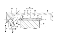
- one shroud-side fin 44 protruding from the central portion of the moving blade shroud 41 in the central axis direction Da toward the casing 2 in the present embodiment, and on the upstream side in the central axial direction Da. It is provided so as to be sandwiched between the casing side fins 42 from the downstream side.
- the shroud-side fin 44 has a thin plate shape extending from the blade shroud 41 toward the outside in the radial direction Dr.
- a clear lance (a minute gap) is formed in the radial direction Dr between the tip portion of the shroud-side fin 44 and the casing 2.
- the stationary blade stage 6 is provided with a plurality of stages on the inner peripheral surface of the casing 2 at intervals along the central axis direction Da.
- Each stationary blade stage 6 is arranged on the upstream side of each moving blade stage 3.
- Each stationary blade stage 6 has a plurality of stationary blades 7 arranged at intervals in the circumferential direction around the central axis Ac.
- the stationary blade 7 includes a stationary blade body 70 and a stationary blade shroud 71.
- the stationary blade body 70 is provided so as to extend from the inner peripheral surface 2S of the casing 2 toward the inside in the radial direction Dr.
- the stationary blade body 70 has a blade-shaped cross section as viewed from the radial direction Dr.
- the stationary blade shroud 71 is attached to the inner end of the stationary blade body 70 in the radial direction Dr.
- the outer peripheral surface 1S of the rotary shaft 1 is recessed from the outer peripheral surface 1S toward the inner side in the radial direction Dr.
- a groove-shaped stationary blade housing recess 8 that is continuous in the direction is formed.
- the stationary blade shroud 71 of each stationary blade 7 is accommodated in the stationary blade accommodating recess 8.
- the moving blade accommodating recess 20 is a so-called cavity formed between the moving blade shroud 41 and the casing 2.
- the surface facing the downstream side in the moving blade housing recess 20 and the end surface facing the upstream side of the moving blade shroud 41 are arranged with a gap in the radial direction, that is, the downstream side of the moving blade housing recess 20
- the facing surface is disposed on the upstream side of the end surface facing the upstream side of the moving blade shroud 41 so as to face the moving blade shroud 41. This gap is the entrance of the cavity.
- the moving blade housing recess 20 which is the inner surface of the casing 2 has a plane 21 extending in the radial direction Dr perpendicular to the central axis Ac inside the radial direction Dr, and a radial direction Dr of the plane 21 as a surface facing the downstream side. And an upstream-side inclined inner wall surface 22 that inclines toward the downstream side toward the outside in the radial direction Dr.
- the connecting portion between the upstream inclined inner wall surface 22 and the flat surface 21 has no corners and is smoothly connected in an arc shape.
- the connecting portion between the bottom surface 23 of the moving blade housing recess 20 and the upstream inclined inner wall surface 22 has no corners and is smoothly connected in an arc shape.
- the upstream inclined inner wall surface 22 may be formed by attaching another member to the moving blade housing recess 20 or may be provided by forming the surface of the moving blade housing recess 20 in an inclined surface shape.
- the end surface facing the upstream side of the rotor blade shroud 41 is a planar upstream inclined surface 45 that is inclined toward the downstream side toward the outside in the radial direction Dr.
- the inclination angle ⁇ 2 of the upstream inclined surface 45 with respect to the central axis Ac is larger than the inclination angle ⁇ 1 of the upstream inclined inner wall surface 22 with respect to the central axis Ac.
- the end position P1 inside the radial direction Dr of the upstream inclined surface 45 that is, the end position P1 inside the radial direction Dr of the rotor blade shroud 41 is the end of the upstream inclined inner wall surface 22 in the radial direction. It is located radially outside the part position P2.
- the upstream blade inclined surface 45 is provided on the moving blade shroud 41 at the inlet portion of the cavity between the casing 2 and the moving blade shroud 41, and the casing 2. Is provided with an upstream inclined inner wall surface 22. For this reason, the leak flow LF that branches off from the main flow MF of steam and flows into the cavity is not straight toward the outside in the radial direction Dr, but along the upstream inclined surface 45 and the upstream inclined inner wall surface 22. It flows obliquely toward the downstream side.
- the leak flow LF when the leak flow LF branches from the main flow MF does not branch in a completely different direction from the main flow MF.
- the upstream inclined surface 45 and the upstream inclined inner wall surface 22 can avoid the formation of corners in the moving blade housing recess 20, so that the occurrence of dead water areas can be suppressed.
- the loss by the branch from the main flow MF of the leak flow LF is suppressed, and the high performance of the steam turbine 100 can be achieved.
- the steam flowing along the upstream inclined surface 45 comes into contact with the casing-side fin 42 and flows so as to be pushed back toward the upstream side.
- a vortex V1 (see FIG. 2) is formed on the upstream side of the casing-side fin 42 in the cavity.
- the vortex V1 is formed so as to extend obliquely toward the downstream side along the upstream inclined surface 45 and the upstream inclined inner wall surface 22 toward the outside in the radial direction Dr.
- the vortex V1 is formed along the flow direction of the leak flow LF branched from the main flow MF. Therefore, it is possible to suppress the formation of fine vortices around the vortex V1, and to suppress the occurrence of shaft vibration on the rotary shaft 1 or the like.
- the inclination angle of the upstream inclined inner wall surface 22 ⁇ 1 ⁇ the inclination angle of the upstream inclined surface 45: ⁇ 2.
- the peeled vapor can be guided and brought into contact with the root of the casing-side fin 42 on the most upstream side.
- the leak flow LF does not flow into the minute gap at the tip of the casing-side fin 42 as it is, and the casing-side fin 42 pushes the leak flow LF upstream, thereby passing through the cavity and downstream of the cavity.
- the flow rate of the leak flow LF that merges from the side (exit portion) to the main flow MF can be reduced.
- the radially inner end position of the upstream inclined surface 45 is positioned more radially outward than the radially outer end position of the upstream inclined inner wall surface 22. Therefore, the vortex V1 formed at the entrance of the cavity can be greatly formed along the flow direction of the leak flow LF branched from the main flow MF. Therefore, it can suppress that a fine vortex is formed around this vortex V1, and can suppress that an axial vibration arises in the rotating shaft 1.
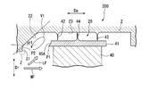
- the end surface facing the upstream side of the moving blade shroud 41 is an upstream inclined surface 45A that is inclined toward the downstream side toward the outside in the radial direction Dr.
- the upstream inclined surface 45A is a curved concave surface that is concave toward the downstream side.
- the curvature of the curved concave surface may be determined so as to follow the shape of the vortex V1.
- the upstream inclined surface can be aligned with the shape of the vortex V1 formed at the inlet of the cavity by forming the curved concave surface as the upstream inclined surface 45A. . Therefore, friction loss between the vortex V1 and the upstream inclined surface 45A can be reduced, loss due to branching of the leak flow LF can be suppressed, and high performance of the steam turbine 200 can be achieved.
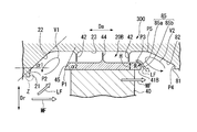
- the surface facing the upstream side of the moving blade housing recess 20 ⁇ / b> B and the end surface facing the downstream side of the moving blade shroud 41 ⁇ / b> B are spaced apart from each other in the radial direction.
- the surface facing the downstream side of the housing recess 20B is arranged to face the blade shroud 41B at a position downstream of the end surface facing the downstream side of the blade shroud 41B. This gap is the exit of the cavity.
- the leak flow LF which is steam that has passed through a minute gap formed between the casing-side fin 42 disposed on the most downstream side and the blade shroud 41B, joins the main flow MF.
- the connecting portion between the downstream inclined inner wall surface 82 and the flat surface 81 has no corners and is smoothly connected in an arc shape. Further, the connecting portion between the bottom surface 23 of the moving blade housing recess 20 and the downstream inclined inner wall surface 82 is smoothly connected in an arc shape without corners.
- the downstream inclined inner wall surface 82 may be formed by attaching another member to the moving blade housing recess 20B, or may be provided by forming the surface of the moving blade housing recess 20 in an inclined surface shape.
- the moving blade shroud 41B has a curved downstream inclined surface 85 inclined toward the downstream side toward the outer side in the radial direction Dr, and an inner side in the radial direction Dr of the downstream inclined surface 85 on the end surface facing the downstream side. And a plane 86 extending in the radial direction Dr.
- the downstream inclined surface 85 is formed in an R surface shape.
- the radially outer end position P3 of the downstream inclined surface 85 is positioned more radially outward than the radially inner end position P4 of the downstream inclined inner wall surface 82.
- the end position P5 on the radially outer side of the downstream inclined inner wall surface 82 is located on the downstream side of the end face facing the downstream side of the moving blade shroud 41B.
- the downstream inclined surface 85 has a curved convex surface 85a that is convex toward the downstream side, and a flat surface 85b that extends continuously in the radial direction Dr inside the radial direction Dr of the curved convex surface 85a.
- a flat inclined surface may be formed instead of the curved convex surface 85a.
- the moving blade shroud 41B is provided with the downstream inclined surface 85, and the casing 2 is provided with the downstream inclined inner wall surface 82.
- the leak flow LF tries to join the main flow MF
- the leak flow LF is not straight in the radial direction, but the leak flow LF is directed in the radial direction Dr along the downstream inclined surface 85 and the downstream inclined inner wall surface 82 toward the downstream side.
- Dr the leak flow LF
- the flow direction of the leak flow LF and the flow direction of the main flow MF can be made as close as possible. Furthermore, since it is possible to avoid the formation of a corner in the moving blade housing recess 20 by the downstream inclined surface 85 and the downstream inclined inner wall surface 82, it is possible to suppress the occurrence of a dead water area. As a result, it is possible to suppress loss of vapor and reduce loss. Thereby, the loss by the merge of the leak flow LF to the main flow MF can be suppressed, and the high performance of the steam turbine 300 can be achieved. As a result, the loss due to the merge of the leak flow LF to the main flow MF is suppressed, and the performance of the steam turbine 300 can be improved.
- the casing-side fins 42 at the outlet of the cavity are caused by the leak flow LF that has been jetted through a minute gap between the casing-side fins 42 disposed on the most downstream side and the blade shroud 41B.
- a vortex V2 is formed on the downstream side.
- the vortex V2 is formed so as to extend obliquely toward the downstream side along the downstream inclined surface 85 and the downstream inclined inner wall surface 82 toward the inside in the radial direction Dr.
- the radially outer end position of the downstream inclined surface 85 is positioned more radially outward than the radially inner end position of the downstream inclined inner wall surface 82. For this reason, the vortex V2 can be formed largely along the flow direction of the leak flow that merges into the main flow at the exit of the cavity, and the formation of fine vortices around the vortex V2 can be suppressed. It is possible to suppress the occurrence of axial vibration.
- the leak flow LF flowing along the surface of the rotor blade shroud 41B does not flow straight toward the main flow MF in the radial direction toward the downstream side, and is not separated from the curved convex surface 85a to some extent.
- the leak flow LF can be merged with the main flow MF after flowing obliquely to the main flow.
- the leak flow LF is positioned on the rear side from the cavity outlet.
- the leak flow LF can be merged with the main flow MF along the flow direction of the main flow MF while avoiding direct inflow into the stationary vane 7. Therefore, the mixing loss of the leak flow LF to the main flow MF can be reduced.
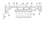
- the upstream side inclined inner wall surface 22 (and the downstream side inclined inner wall surface 82) is provided in the moving blade housing recess 20, and the upstream side inclined surface 45 (45 A) (and the downstream side inclined surface) is provided on the moving blade shroud 41.
- the surface 85) is provided, the present invention is not limited to this. That is, an upstream inclined inner wall surface (and downstream inclined inner wall surface) may be provided in the stationary blade accommodating recess 8, and an upstream inclined surface (and downstream inclined surface) may be provided in the stationary blade shroud 71.
- the aspect of the axial flow rotary machine is not limited to the steam turbine, and other devices such as a gas turbine and an aircraft jet engine can be applied as the axial flow rotary machine.
- the upstream inclined surface and the upstream inclined inner wall surface at the entrance of the cavity between the structure and the blade suppress the loss due to the branching of the leak flow from the main flow. Performance improvement is possible.
Landscapes
- Engineering & Computer Science (AREA)
- General Engineering & Computer Science (AREA)
- Mechanical Engineering (AREA)
- Chemical & Material Sciences (AREA)
- Combustion & Propulsion (AREA)
- Turbine Rotor Nozzle Sealing (AREA)
- Sealing Using Fluids, Sealing Without Contact, And Removal Of Oil (AREA)
Priority Applications (3)
| Application Number | Priority Date | Filing Date | Title |
|---|---|---|---|
| DE112018000966.1T DE112018000966T5 (de) | 2017-02-23 | 2018-02-23 | Axial-turbomaschine |
| US16/487,200 US11066946B2 (en) | 2017-02-23 | 2018-02-23 | Axial turbomachinery |
| CN201880012746.0A CN110312847A (zh) | 2017-02-23 | 2018-02-23 | 轴流旋转机械 |
Applications Claiming Priority (2)
| Application Number | Priority Date | Filing Date | Title |
|---|---|---|---|
| JP2017032371A JP6706585B2 (ja) | 2017-02-23 | 2017-02-23 | 軸流回転機械 |
| JP2017-032371 | 2017-02-23 |
Publications (1)
| Publication Number | Publication Date |
|---|---|
| WO2018155652A1 true WO2018155652A1 (ja) | 2018-08-30 |
Family
ID=63253827
Family Applications (1)
| Application Number | Title | Priority Date | Filing Date |
|---|---|---|---|
| PCT/JP2018/006802 Ceased WO2018155652A1 (ja) | 2017-02-23 | 2018-02-23 | 軸流回転機械 |
Country Status (5)
| Country | Link |
|---|---|
| US (1) | US11066946B2 (enExample) |
| JP (1) | JP6706585B2 (enExample) |
| CN (1) | CN110312847A (enExample) |
| DE (1) | DE112018000966T5 (enExample) |
| WO (1) | WO2018155652A1 (enExample) |
Families Citing this family (2)
| Publication number | Priority date | Publication date | Assignee | Title |
|---|---|---|---|---|
| JP7235595B2 (ja) * | 2019-05-31 | 2023-03-08 | 三菱重工業株式会社 | 回転機械 |
| DE102024115122A1 (de) | 2024-05-29 | 2025-12-04 | Ebm-Papst Mulfingen Gmbh & Co. Kg | Berührungslose dynamische Dichtung zur Abdichtung eines Radialspalts |
Citations (4)
| Publication number | Priority date | Publication date | Assignee | Title |
|---|---|---|---|---|
| JPS6397804A (ja) * | 1986-10-13 | 1988-04-28 | Toshiba Corp | 蒸気タービン |
| JP2009243287A (ja) * | 2008-03-28 | 2009-10-22 | Toshiba Corp | 軸流タービン |
| US20110070074A1 (en) * | 2009-09-24 | 2011-03-24 | Rolls-Royce Deutschland Ltd & Co Kg | Gas turbine with a shroud and labyrinth-type sealing arrangement |
| JP2011085138A (ja) * | 2009-10-14 | 2011-04-28 | General Electric Co <Ge> | 間隙流れ制御のための渦チャンバ |
Family Cites Families (17)
| Publication number | Priority date | Publication date | Assignee | Title |
|---|---|---|---|---|
| JPS5114402A (ja) | 1974-07-25 | 1976-02-04 | Ueno Chem Ind | Ofusetsutoinsatsuban mataha shotsukotsushikiinsatsubanno seizohohono kairyonarabinisoreni shosuru genzoratsukaa |
| JPS6123804A (ja) * | 1984-07-10 | 1986-02-01 | Hitachi Ltd | タ−ビン段落構造 |
| JPH10311205A (ja) * | 1997-05-14 | 1998-11-24 | Toshiba Corp | 軸流タービン |
| JP2007138864A (ja) | 2005-11-21 | 2007-06-07 | Toshiba Corp | 蒸気タービン段落および蒸気タービン |
| JP2011080452A (ja) | 2009-10-09 | 2011-04-21 | Mitsubishi Heavy Ind Ltd | タービン |
| US8920126B2 (en) * | 2009-12-07 | 2014-12-30 | Mitsubishi Heavy Industries, Ltd. | Turbine and turbine rotor blade |
| JP5709447B2 (ja) | 2010-09-28 | 2015-04-30 | 三菱日立パワーシステムズ株式会社 | タービン |
| JP5517910B2 (ja) | 2010-12-22 | 2014-06-11 | 三菱重工業株式会社 | タービン、及びシール構造 |
| JP5518022B2 (ja) * | 2011-09-20 | 2014-06-11 | 三菱重工業株式会社 | タービン |
| JP5916458B2 (ja) | 2012-03-23 | 2016-05-11 | 三菱日立パワーシステムズ株式会社 | タービン |
| US9260972B2 (en) * | 2012-07-03 | 2016-02-16 | United Technologies Corporation | Tip leakage flow directionality control |
| WO2014010052A1 (ja) * | 2012-07-11 | 2014-01-16 | 株式会社日立製作所 | 軸流流体機械 |
| JP6131177B2 (ja) * | 2013-12-03 | 2017-05-17 | 三菱重工業株式会社 | シール構造、及び回転機械 |
| JP6296649B2 (ja) | 2014-03-04 | 2018-03-20 | 三菱日立パワーシステムズ株式会社 | シール構造、及び回転機械 |
| JP2016089768A (ja) * | 2014-11-07 | 2016-05-23 | 三菱日立パワーシステムズ株式会社 | シール装置及びターボ機械 |
| JP6530918B2 (ja) * | 2015-01-22 | 2019-06-12 | 三菱日立パワーシステムズ株式会社 | タービン |
| JP6209200B2 (ja) * | 2015-12-09 | 2017-10-04 | 三菱日立パワーシステムズ株式会社 | ステップシール,シール構造,ターボ機械及びステップシールの製造方法 |
-
2017
- 2017-02-23 JP JP2017032371A patent/JP6706585B2/ja active Active
-
2018
- 2018-02-23 WO PCT/JP2018/006802 patent/WO2018155652A1/ja not_active Ceased
- 2018-02-23 CN CN201880012746.0A patent/CN110312847A/zh active Pending
- 2018-02-23 DE DE112018000966.1T patent/DE112018000966T5/de not_active Withdrawn
- 2018-02-23 US US16/487,200 patent/US11066946B2/en not_active Expired - Fee Related
Patent Citations (4)
| Publication number | Priority date | Publication date | Assignee | Title |
|---|---|---|---|---|
| JPS6397804A (ja) * | 1986-10-13 | 1988-04-28 | Toshiba Corp | 蒸気タービン |
| JP2009243287A (ja) * | 2008-03-28 | 2009-10-22 | Toshiba Corp | 軸流タービン |
| US20110070074A1 (en) * | 2009-09-24 | 2011-03-24 | Rolls-Royce Deutschland Ltd & Co Kg | Gas turbine with a shroud and labyrinth-type sealing arrangement |
| JP2011085138A (ja) * | 2009-10-14 | 2011-04-28 | General Electric Co <Ge> | 間隙流れ制御のための渦チャンバ |
Also Published As
| Publication number | Publication date |
|---|---|
| JP6706585B2 (ja) | 2020-06-10 |
| US20190376403A1 (en) | 2019-12-12 |
| DE112018000966T5 (de) | 2019-10-31 |
| US11066946B2 (en) | 2021-07-20 |
| CN110312847A (zh) | 2019-10-08 |
| JP2018135846A (ja) | 2018-08-30 |
Similar Documents
| Publication | Publication Date | Title |
|---|---|---|
| US9726027B2 (en) | Turbine | |
| KR101305575B1 (ko) | 터빈 동익 및 터보 기계 | |
| JP5995958B2 (ja) | ターボ機械タービンノズル用の封止装置 | |
| JP2010156335A (ja) | 改良型タービン翼プラットフォームの輪郭に関する方法および装置 | |
| US8561997B2 (en) | Adverse pressure gradient seal mechanism | |
| JP5651459B2 (ja) | タービンエンジンにおける圧縮機の動作に関するシステム及び装置 | |
| JP2002371802A (ja) | ガスタービンにおけるシュラウド一体型動翼と分割環 | |
| CN103291379B (zh) | 涡轮机 | |
| CN107208493B (zh) | 涡轮 | |
| WO2018155636A1 (ja) | 軸流回転機械 | |
| JP2020020465A (ja) | シール装置およびターボ機械 | |
| JP6706585B2 (ja) | 軸流回転機械 | |
| CN113383147B (zh) | 旋转机械 | |
| US10794397B2 (en) | Rotor blade and axial flow rotary machine | |
| CN115280049B (zh) | 密封装置及旋转机械 | |
| JP2005146977A (ja) | 軸流タービンの静動翼間構造及びこれを用いた軸流タービン機械 | |
| JP7130575B2 (ja) | 軸流タービン | |
| JP6994976B2 (ja) | タービンの排気室及びタービン | |
| JP6803772B2 (ja) | 軸流回転機械、及び、動翼 | |
| JP6638938B2 (ja) | 回転機械 | |
| JP2019100204A (ja) | タービン、動翼 |
Legal Events
| Date | Code | Title | Description |
|---|---|---|---|
| 121 | Ep: the epo has been informed by wipo that ep was designated in this application |
Ref document number: 18757374 Country of ref document: EP Kind code of ref document: A1 |
|
| 122 | Ep: pct application non-entry in european phase |
Ref document number: 18757374 Country of ref document: EP Kind code of ref document: A1 |