WO2018155248A1 - 非水電解質二次電池 - Google Patents
非水電解質二次電池 Download PDFInfo
- Publication number
- WO2018155248A1 WO2018155248A1 PCT/JP2018/004778 JP2018004778W WO2018155248A1 WO 2018155248 A1 WO2018155248 A1 WO 2018155248A1 JP 2018004778 W JP2018004778 W JP 2018004778W WO 2018155248 A1 WO2018155248 A1 WO 2018155248A1
- Authority
- WO
- WIPO (PCT)
- Prior art keywords
- positive electrode
- negative electrode
- electrode plate
- resin tape
- mixture layer
- Prior art date
- Legal status (The legal status is an assumption and is not a legal conclusion. Google has not performed a legal analysis and makes no representation as to the accuracy of the status listed.)
- Ceased
Links
Images
Classifications
-
- H—ELECTRICITY
- H01—ELECTRIC ELEMENTS
- H01M—PROCESSES OR MEANS, e.g. BATTERIES, FOR THE DIRECT CONVERSION OF CHEMICAL ENERGY INTO ELECTRICAL ENERGY
- H01M10/00—Secondary cells; Manufacture thereof
- H01M10/05—Accumulators with non-aqueous electrolyte
-
- H—ELECTRICITY
- H01—ELECTRIC ELEMENTS
- H01M—PROCESSES OR MEANS, e.g. BATTERIES, FOR THE DIRECT CONVERSION OF CHEMICAL ENERGY INTO ELECTRICAL ENERGY
- H01M10/00—Secondary cells; Manufacture thereof
- H01M10/05—Accumulators with non-aqueous electrolyte
- H01M10/058—Construction or manufacture
- H01M10/0587—Construction or manufacture of accumulators having only wound construction elements, i.e. wound positive electrodes, wound negative electrodes and wound separators
-
- Y—GENERAL TAGGING OF NEW TECHNOLOGICAL DEVELOPMENTS; GENERAL TAGGING OF CROSS-SECTIONAL TECHNOLOGIES SPANNING OVER SEVERAL SECTIONS OF THE IPC; TECHNICAL SUBJECTS COVERED BY FORMER USPC CROSS-REFERENCE ART COLLECTIONS [XRACs] AND DIGESTS
- Y02—TECHNOLOGIES OR APPLICATIONS FOR MITIGATION OR ADAPTATION AGAINST CLIMATE CHANGE
- Y02E—REDUCTION OF GREENHOUSE GAS [GHG] EMISSIONS, RELATED TO ENERGY GENERATION, TRANSMISSION OR DISTRIBUTION
- Y02E60/00—Enabling technologies; Technologies with a potential or indirect contribution to GHG emissions mitigation
- Y02E60/10—Energy storage using batteries
-
- Y—GENERAL TAGGING OF NEW TECHNOLOGICAL DEVELOPMENTS; GENERAL TAGGING OF CROSS-SECTIONAL TECHNOLOGIES SPANNING OVER SEVERAL SECTIONS OF THE IPC; TECHNICAL SUBJECTS COVERED BY FORMER USPC CROSS-REFERENCE ART COLLECTIONS [XRACs] AND DIGESTS
- Y02—TECHNOLOGIES OR APPLICATIONS FOR MITIGATION OR ADAPTATION AGAINST CLIMATE CHANGE
- Y02P—CLIMATE CHANGE MITIGATION TECHNOLOGIES IN THE PRODUCTION OR PROCESSING OF GOODS
- Y02P70/00—Climate change mitigation technologies in the production process for final industrial or consumer products
- Y02P70/50—Manufacturing or production processes characterised by the final manufactured product
Definitions
- the present invention relates to a nonaqueous electrolyte secondary battery having a flat wound electrode body.
- Non-aqueous electrolyte secondary batteries are widely used as driving power sources for portable electronic devices such as smartphones, tablet computers, notebook computers, and portable music players.
- portable electronic devices such as smartphones, tablet computers, notebook computers, and portable music players.
- a pouch-type non-aqueous electrolyte secondary battery using a pouch exterior body made of a laminate sheet as the exterior body is suitable.
- a flat wound electrode body is used for a pouch-type nonaqueous electrolyte secondary battery.
- the wound electrode body is produced by winding a plate group consisting of a positive electrode plate, a negative electrode plate, and a separator interposed therebetween in a flat shape along the core axis.
- curved portions are formed in which the electrode plate group is convexly curved outward from the electrode body.
- a non-aqueous electrolyte secondary battery is designed such that the ratio of the charge capacity of the negative electrode to the charge capacity of the positive electrode (positive / negative electrode capacity ratio) is greater than 1. Thereby, precipitation of lithium on the negative electrode during charging is prevented.
- the design value of the positive / negative electrode capacity ratio is determined based on the amount of active material per unit area of each of the positive electrode plate and the negative electrode plate. However, in the curved portion of the flat electrode body, since the outer electrode plate wraps the inner electrode plate, the outer electrode plate has a larger occupied volume in the bent portion.
- the positive / negative electrode capacity ratio between the outer surface of the negative electrode plate (the outer surface in the radial direction of the electrode body) and the inner surface of the winding electrode of the positive electrode plate (the inner surface in the radial direction of the electrode body) is smaller than the design value. End up.
- the difference between the positive and negative electrode capacity ratios as described above becomes larger toward the inner peripheral side of the electrode body. Therefore, the negative electrode may be excessively charged in the portion closest to the winding start side in the positive and negative electrode facing portions in the curved portion. Such a problem hardly occurs when the design value of the positive / negative electrode capacity ratio is sufficiently large.
- it is desirable to reduce the positive / negative electrode capacity ratio as much as possible in order to increase the capacity of the non-aqueous electrolyte secondary battery means for solving the above-mentioned problems have been studied.
- Patent Document 1 discloses that lithium deposition on the negative electrode is prevented by sticking an insulating resin tape to the inner surface of the winding portion of the positive electrode plate that is curved on the most winding start side.
- Patent Document 2 discloses a battery in which a portion on the innermost periphery of the curved portion of the facing portions of the positive and negative electrode active material layers does not participate in charging / discharging. Specifically, as in Patent Document 1, it is disclosed that an insulating resin tape is adhered to the wound inner surface of the portion of the positive electrode plate that is curved on the most winding start side.
- Patent Document 1 describes that the positive electrode core body is prevented from being damaged by sticking a resin tape to the positive electrode plate. However, the effect is due to the curvature of the curved portion being reduced by the application of the resin tape. In any of Patent Documents 1 and 2, no consideration is given to the loss of flexibility of the positive electrode plate due to sticking of the resin tape.
- the present invention has been made in view of the above, and an object of the present invention is to prevent local overcharge of the negative electrode in the curved portion of the flat electrode body and to suppress cracking of the positive electrode core in the curved portion. .
- a non-aqueous electrolyte secondary battery is a flat electrode in which a positive electrode plate, a negative electrode plate, and an electrode plate group having a separator interposed therebetween are wound.
- the positive electrode plate has a positive electrode core and a positive electrode mixture layer formed on the surface thereof
- the negative electrode plate has a negative electrode core and a negative electrode mixture layer formed on the surface thereof.
- the electrode body has curved portions where the electrode plate group is curved at both ends in the major axis direction of the cross section perpendicular to the winding axis.
- the resin tape is stuck to the part arrange
- the resin tape includes an adhesive layer and a base material layer that does not transmit lithium ions.
- the adhesive strength of the resin tape to the positive electrode mixture layer is 0.1 N / cm or more and 2 N / cm or less.
- local overcharge of the negative electrode in the curved portion of the flat electrode body can be prevented, and cracks in the positive electrode core in the curved portion can be suppressed.
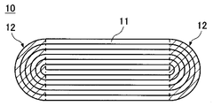
- FIG. 1 is a schematic cross-sectional view of a flat electrode body according to an embodiment.
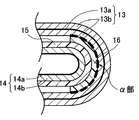
- FIG. 2 is an enlarged view of a main part of the bending portion of FIG.
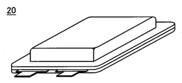
- FIG. 3 is a perspective view of the nonaqueous electrolyte secondary battery according to the example.
- FIGS. 1 and 2 schematically showing a cross section perpendicular to the winding axis of a flat electrode body.
- the electrode body 10 can be produced, for example, by winding the positive electrode plate 13 and the negative electrode plate 14 via a separator 15 and forming the wound electrode body into a flat shape by pressing.
- the cross section perpendicular to the winding axis of the flat electrode body 10 has a pair of electrode plates 11 in which a positive electrode plate 13, a negative electrode plate 14, and a separator 15 are stacked. It has a structure in which layers are stacked sequentially from the inner side to the outer side (radially outer side). At both ends in the major axis direction of the cross section, curved portions 12 where the electrode plate group 11 is curved are formed.
- the resin tape 16 is affixed to the part (alpha part shown with the dotted line of FIG. 2) arrange
- the resin tape 16 is preferably attached so as to cover the entire range of the ⁇ portion, and a part of the resin tape 16 may be attached so as to exceed the ⁇ portion.
- the position where the resin tape 16 is attached is not limited to the ⁇ part, and the resin tape may also be attached to the surface of the positive electrode mixture layer 13b outside the ⁇ part. However, if the resin tape 16 is attached to the ⁇ portion, local overcharge of the negative electrode can be effectively prevented. Since the range occupied by the ⁇ portion is extremely small compared to the total area of the front and back surfaces of the positive electrode plate, the influence of the resin tape 16 on the ⁇ portion on the battery capacity is small.
- the positive electrode mixture layer 13b is formed on both surfaces of the positive electrode core body 13a.
- the negative electrode mixture layer 14b is disposed so as to face the positive electrode mixture layer 13b with the separator 15 interposed therebetween. Since the positive electrode plate 13 does not exist on the innermost winding side of the negative electrode plate 14, the negative electrode mixture layer 14 b is not formed on the inner surface of the innermost negative electrode core 14 a of the negative electrode plate 14.
- the illustration of the separator 15 existing inside the innermost periphery of the negative electrode plate 14 is omitted.
- the resin tape includes at least two layers of a base material layer that does not transmit lithium ions in the non-aqueous electrolyte and an adhesive layer.
- a base material layer that does not transmit lithium ions By including the base material layer that does not transmit lithium ions, the charge / discharge reaction does not occur in the opposite portion of the positive and negative electrodes in the ⁇ portion, thereby preventing local overcharge of the negative electrode.
- any resin film that can stably exist without transmitting lithium ions in the nonaqueous electrolyte can be used without limitation.
- the resin material used for the base material layer include polyethylene, polypropylene, polyethylene terephthalate, polyvinyl alcohol, and polyimide.
- the thickness of a base material layer is not specifically limited, Since the softness
- the adhesive strength of the resin tape to the positive electrode mixture layer is preferably 2 N / cm or less. If the adhesive strength of the resin tape to the positive electrode mixture layer is 2 N / cm or less, a part of the adhesive layer peels off from the positive electrode mixture layer when the portion where the resin tape is attached is curved with a large curvature. Fine cracks are generated in the positive electrode mixture layer. Thereby, the softness
- the adhesive strength of the resin tape to the positive electrode mixture layer 13b is preferably 0.1 N / cm or more.
- the pressure-sensitive adhesive used for the pressure-sensitive adhesive layer of the resin tape examples include, but are not limited to, acrylic and rubber-based pressure-sensitive adhesives.
- the adhesive strength of the resin tape to the positive electrode mixture layer can be adjusted by changing the components of the adhesive and the thickness of the adhesive layer. For example, if the thickness of the pressure-sensitive adhesive layer is 3 ⁇ m or less, the amount of the pressure-sensitive adhesive penetrating into the positive electrode mixture layer can be suppressed. Therefore, the adhesive force of the resin tape to the positive electrode mixture layer can be easily adjusted to 2 N / cm or less. Can do. Since the resin tape needs to maintain the state of being stuck to the positive electrode mixture layer until the electrode plate group is wound, the thickness of the pressure-sensitive adhesive layer is preferably 0.1 ⁇ m or more.
- the mixture layer can be formed by applying and drying a mixture slurry prepared by kneading an active material together with a binder in a dispersion medium on a core. The dried mixture layer is compressed to a predetermined thickness. A conductive agent and a thickener can be added to the mixture slurry as necessary.
- a metal foil is preferably used for the core, an aluminum foil is preferably used for the positive electrode core, and a copper foil is preferably used for the negative electrode core. Both aluminum foil and copper foil can contain a trace amount of different metals.
- a lithium transition metal composite oxide capable of reversibly occluding and releasing lithium ions
- the lithium transition metal composite oxide include general formula LiMO 2 (M is at least one of Co, Ni and Mn), LiMn 2 O 4 and LiFePO 4 . These can be used individually by 1 type or in mixture of 2 or more types, At least 1 chosen from the group which consists of Al, Ti, Mg, and Zr can be added or substituted with a transition metal element.
- carbon materials such as artificial graphite, natural graphite, non-graphitizable carbon, and graphitizable carbon that can reversibly occlude and release lithium ions can be used. Further, silicon and tin, oxides thereof, and the like can also be used. These can be used individually by 1 type or in mixture of 2 or more types.
- a microporous film made of polyolefin such as polyethylene or polypropylene can be used as the separator.
- a separator in which a plurality of microporous films having different compositions are stacked can be used.
- a laminated separator it is preferable to adopt a three-layer structure in which a layer mainly composed of polyethylene having a low melting point is used as an intermediate layer and a layer mainly composed of polypropylene having excellent oxidation resistance is used as a surface layer.
- the intermediate layer mainly composed of polyethylene exhibits a shutdown function that closes the separator and cuts off the current between the positive and negative electrodes when the battery temperature rises.
- inorganic particles such as aluminum oxide (Al 2 O 3 ), titanium oxide (TiO 2 ), and silicon oxide (SiO 2 ) can be added to the separator.
- inorganic particles can be carried in the separator and can be applied together with a binder on the separator surface.
- an aramid resin having excellent heat resistance can be applied to the separator surface.
- non-aqueous electrolyte a solution obtained by dissolving a lithium salt as an electrolyte salt in a non-aqueous solvent can be used.
- a non-aqueous solvent or a non-aqueous electrolyte using a gel polymer together with the non-aqueous solvent can be used.
- a cyclic carbonate, a chain carbonate, a cyclic carboxylic acid ester and a chain carboxylic acid ester can be used, and it is preferable to use a mixture of two or more.
- the cyclic carbonate include ethylene carbonate (EC), propylene carbonate (PC), and butylene carbonate (BC).
- a cyclic carbonate in which part of hydrogen is substituted with fluorine, such as fluoroethylene carbonate (FEC) can also be used.
- the chain carbonate include dimethyl carbonate (DMC), ethyl methyl carbonate (EMC), diethyl carbonate (DEC), and methyl propyl carbonate (MPC).
- Examples of cyclic carboxylic acid esters include ⁇ -butyrolactone ( ⁇ -BL) and ⁇ -valerolactone ( ⁇ -VL).
- Examples of chain carboxylic acid esters include methyl pivalate, ethyl pivalate, methyl isobutyrate and methyl pro Pionate is exemplified.
- LiPF 6 , LiBF 4 , LiCF 3 SO 3 , LiN (CF 3 SO 2 ) 2 , LiN (C 2 F 5 SO 2 ) 2 , LiN (CF 3 SO 2 ) (C 4 F 9 SO 2 ) LiC (CF 3 SO 2 ) 3 , LiC (C 2 F 5 SO 2 ) 3 , LiAsF 6 , LiClO 4 , Li 2 B 10 Cl 10 and Li 2 B 12 Cl 12 are exemplified.
- LiPF 6 is particularly preferable, and the concentration in the nonaqueous electrolyte is preferably 0.5 to 2.0 mol / L.
- Another lithium salt such as LiBF 4 can be mixed with LiPF 6 .
- a pouch-shaped exterior body made of a laminate sheet or a rectangular exterior can made of aluminum can be used.
- Preparation of positive electrode plate 95 parts by mass of lithium cobaltate (LiCoO 2 ) as the positive electrode active material, 2.5 parts by mass of carbon black as the conductive agent, and 2.5 parts by mass of polyvinylidene fluoride (PVdF) as the binder Mixed.
- the mixture was charged into N-methylpyrrolidone (NMP) as a dispersion medium and kneaded to prepare a positive electrode mixture slurry.
- NMP N-methylpyrrolidone
- the positive electrode mixture slurry was applied to both surfaces of a positive electrode core body made of an aluminum foil having a thickness of 12 ⁇ m and dried to form a positive electrode mixture layer. At this time, a positive electrode core exposed portion in which the positive electrode mixture layer was not formed was provided on a part of the positive electrode core.
- the positive electrode mixture layer after drying was compressed with a roller so as to have a packing density of 3.6 g / cm 3 and cut into a predetermined size. Finally, a positive electrode tab made of aluminum was joined to the exposed portion of the positive electrode core to produce a positive electrode plate.
- the dried negative electrode mixture layer was compressed with a roller so that the filling density was 1.6 g / cm 3 , and cut into a predetermined size. Finally, a negative electrode tab made of nickel was joined to the exposed portion of the negative electrode core body to prepare a negative electrode plate.
- An electrode plate group in which a positive electrode plate and a negative electrode plate are laminated via a separator made of a polyethylene microporous film having a thickness of 16 ⁇ m is wound, and the wound electrode body is formed by hot pressing to produce a flat electrode body.
- a resin tape was attached to a portion of the surface of the positive electrode mixture layer in the curved portion of the electrode body that is initially disposed on the curved portion.
- a polyolefin film having a thickness of 12 ⁇ m was used for the base layer of the resin tape.
- An acrylic pressure-sensitive adhesive was used for the pressure-sensitive adhesive layer of the resin tape, and its thickness was 3 ⁇ m.
- a non-aqueous solvent was prepared by mixing ethylene carbonate (EC) and methyl ethyl carbonate (MEC) in a volume ratio of 30:70.
- EC ethylene carbonate
- MEC methyl ethyl carbonate
- LiPF 6 lithium hexafluorophosphate
- VC vinylene carbonate
- the addition amount of vinylene carbonate was 1 mass% with respect to the nonaqueous electrolyte.
- the electrode body produced as described above was housed in a pouch exterior body made of a laminate sheet, and the outer peripheral portion of the pouch exterior body was heat-sealed except for the liquid injection port to prepare a pre-injection battery. After injecting a non-aqueous electrolyte into the pre-injection battery from the injection port, the injection port was heat-sealed to produce a non-aqueous electrolyte secondary battery 20 having a design capacity of 1000 mAh shown in FIG.
- Comparative Example 1 An electrode body and a non-aqueous electrolyte secondary battery according to Comparative Example 1 were produced in the same manner as in the example except that the thickness of the base layer of the resin tape was 20 ⁇ m and the thickness of the pressure-sensitive adhesive layer was 5 ⁇ m.
- Comparative Example 2 The electrode body according to Comparative Example 2 is the same as Comparative Example 1 except that a rubber-based adhesive mainly composed of styrene-butadiene rubber is used in place of the acrylic adhesive and the thickness of the adhesive layer is 10 ⁇ m. And the nonaqueous electrolyte secondary battery was produced.
- Comparative Example 3 An electrode body and a nonaqueous electrolyte secondary battery according to Comparative Example 3 were produced in the same manner as in the example except that the resin tape was not used.
- the adhesive strength of the resin tape to the positive electrode mixture layer was measured as follows. First, a size of 2 cm ⁇ 5 cm is cut out from the portion of the positive electrode plate where the positive electrode mixture layer is formed on both surfaces of the positive electrode core. A resin tape is attached to the surface of the cut out positive electrode plate. The portion of the resin tape that is not attached to the positive electrode plate is 20 mm / min. The resin tape was pulled until it was completely peeled off from the positive electrode plate, and the measured maximum load was defined as the adhesive strength (N / cm) of the resin tape to the positive electrode mixture layer. Table 1 shows the measurement results of the adhesive strength of the resin tapes used in Examples and Comparative Examples 1 and 2 with respect to the positive electrode mixture layer.
- the adhesive force of the resin tape of the example to the positive electrode mixture layer is smaller than the adhesive force of any of the resin tapes of Comparative Examples 1 and 2.
- the resin tape is attached.
- the formed portion is curved, a part of the resin tape is peeled from the positive electrode mixture layer, and a crack is generated in the positive electrode mixture layer.
- the adhesive force with respect to the positive mix layer of the resin tape of an Example is 1.5 N / cm, if the adhesive force is 2 N / cm or less, the effect similar to an Example will be exhibited.
- lithium deposition on the negative electrode facing the ⁇ portion was not confirmed after the charge / discharge cycle. Even if the adhesive strength of the resin tape is reduced, if the resin tape is securely fixed to the ⁇ part of the positive electrode plate during winding of the electrode plate group, the resin tape will not be misaligned during the charge / discharge cycle. Local overcharge can be prevented.
- the present invention local overcharge of the negative electrode in the curved portion of the electrode body can be prevented, and cracks in the positive electrode core can be suppressed.
- the capacity of the nonaqueous electrolyte secondary battery can be increased by reducing the positive / negative electrode capacity ratio. Therefore, the industrial applicability of the present invention is great.
Landscapes
- Engineering & Computer Science (AREA)
- Manufacturing & Machinery (AREA)
- Chemical & Material Sciences (AREA)
- Chemical Kinetics & Catalysis (AREA)
- Electrochemistry (AREA)
- General Chemical & Material Sciences (AREA)
- Secondary Cells (AREA)
Abstract
本発明は、偏平状の巻回電極体の湾曲部における負極の局所的な過剰充電を防止するとともに、湾曲部における正極芯体のクラックを抑制することを目的とする。本発明の一態様に係る非水電解質二次電池は、正極板、負極板、及びそれらの間に介在するセパレータを有する極板群が巻回された偏平状の電極体と、非水電解質と、外装体と、を含む。正極板は、正極芯体とその表面に形成された正極合剤層を有し、負極板は、負極芯体とその表面に形成された負極合剤層を有する。電極体は、巻回軸に垂直な断面の長径方向の両端部に極板群が湾曲している湾曲部を有する。湾曲部内の正極合剤層の巻内側の表面のうち、正極板の最も巻き始め側に配置されている部分に樹脂テープが貼着されている。樹脂テープは粘着剤層と、リチウムイオンを透過しない基材層を含んでいる。樹脂テープの正極合剤層に対する粘着力は、0.1N/cm以上2N/cm以下である。
Description
本発明は、偏平状の巻回電極体を有する非水電解質二次電池に関する。
非水電解質二次電池はスマートフォン、タブレット型コンピュータ、ノートパソコン及び携帯型音楽プレイヤーなどの携帯型電子機器の駆動電源として広く用いられている。特に、薄型の電子機器には外装体としてラミネートシートからなるパウチ外装体を用いたパウチ型の非水電解質二次電池が好適である。
パウチ型の非水電解質二次電池には偏平状の巻回電極体が用いられる。巻回電極体は、正極板、負極板、及びそれらの間に介在するセパレータからなる極板群を巻芯軸に沿って偏平状に巻回して作製される。偏平状の電極体の巻回軸に垂直な断面の長径方向の両端部に、極板群が電極体の外側に凸状に湾曲している湾曲部が形成される。
一般に非水電解質二次電池は、正極の充電容量に対する負極の充電容量の比(正負極容量比)が1より大きくなるように設計されている。これにより、充電時の負極上へのリチウムの析出が防止される。正負極容量比の設計値は正極板と負極板のそれぞれの単位面積当たりの活物質量に基づいて決定される。ところが、偏平状の電極体の湾曲部においては、外周側の極板がその内周側の極板を包み込む構造となっているため、外周側の極板ほど湾曲部における占有体積が大きくなる。そのため、湾曲部では負極板の巻外面(電極体の径方向の外側面)とそれに対向する正極板の巻内面(電極体の径方向の内側面)の正負極容量比が設計値より小さくなってしまう。
上記のような正負極容量比のズレは電極体の内周側ほど大きくなる。そのため、湾曲部における正負極対向部のうち巻き始め側に最も近い部分において負極が過剰に充電される可能性がある。正負極容量比の設計値が十分に大きい場合はそのような問題は生じにくい。しかし、非水電解質二次電池を高容量化するために正負極容量比はできるだけ低減することが望ましいため、上記の問題を解決する手段が検討されている。
特許文献1は正極板の最も巻き始め側で湾曲している部分の巻内面に絶縁性の樹脂テープを貼着することにより、負極上へのリチウムの析出が防止されることを開示している。また、特許文献2は正負極の活物質層の対向部のうち湾曲部の最内周にある部分が充放電に関与しない電池を開示している。具体的には特許文献1と同様に、正極板の最も巻き始め側で湾曲している部分の巻内面に絶縁性の樹脂テープを貼着することが開示されている。
特許文献1及び2が開示している技術によれば、湾曲部における負極の過剰充電を防止することができる。しかし、湾曲部における正極板の表面に樹脂テープを貼着した場合、その樹脂テープに起因して正極芯体にクラックが生じる場合がある。湾曲部に正極合剤層が形成されている場合、正極板が湾曲する際に正極合剤層に微細なクラックが生じることで正極板の柔軟性が担保される。ところが正極合剤層の表面に樹脂テープが貼着されていると、正極合剤層に微細なクラックが生じにくい。そのため、樹脂テープが貼着された部分を大きな曲率で湾曲させようとすると、正極芯体にクラックが生じやすくなる。正極芯体にクラックが生じると充放電サイクルに伴う負極板や正極板の膨張、収縮により正極芯体が破断する可能性が生じる。
特許文献1には樹脂テープを正極板へ貼着することで正極芯体の損傷が防止されることが記載されている。しかし、その効果は樹脂テープの貼着によって湾曲部の曲率が低減されることによるものである。特許文献1及び2のいずれにおいても、樹脂テープの貼着により正極板の柔軟性が失われることについて何ら考慮されていない。
本発明は上記に鑑みてなされたものであり、偏平状の電極体の湾曲部における負極の局所的な過剰充電を防止するとともに、湾曲部における正極芯体のクラックを抑制することを目的とする。
上記課題を解決するために本発明の一態様に係る非水電解質二次電池は、正極板、負極板、及びそれらの間に介在するセパレータを有する極板群が巻回された偏平状の電極体と、非水電解質と、外装体と、を含む。正極板は、正極芯体とその表面に形成された正極合剤層を有し、負極板は、負極芯体とその表面に形成された負極合剤層を有する。電極体は、巻回軸に垂直な断面の長径方向の両端部に極板群が湾曲している湾曲部を有する。湾曲部内の正極合剤層の巻内側の表面のうち、正極板の最も巻き始め側に配置されている部分に樹脂テープが貼着されている。樹脂テープは粘着剤層と、リチウムイオンを透過しない基材層を含んでいる。樹脂テープの正極合剤層に対する粘着力は、0.1N/cm以上2N/cm以下である。
本発明の一態様によれば、偏平状の電極体の湾曲部における負極の局所的な過剰充電を防止するとともに、湾曲部における正極芯体のクラックを抑制することができる。
本発明の一実施形態について、偏平状の電極体の巻回軸に垂直な断面を模式的に示す図1及び2を参照しながら説明する。電極体10は、例えば正極板13及び負極板14をセパレータ15を介して巻回し、その巻回電極体をプレス加工により偏平状に成形して作製することができる。偏平状の電極体10の巻回軸に垂直な断面は、図1に示すように、正極板13、負極板14、及びセパレータ15が積層した1組の極板群11が巻内側(径方向内側)から巻外側(径方向外側)に向かって順次積層した構造を有する。その断面の長径方向の両端部には、極板群11が湾曲している湾曲部12が形成されている。
湾曲部12における正極合剤層13bの巻内側の表面のうち、最も巻き始め側に配置されている部分(図2の点線で示すα部)に樹脂テープ16が貼着されている。樹脂テープ16はα部の全範囲を覆うように貼着されていることが好ましく、樹脂テープ16の一部がα部を超えるように貼着されていてもよい。樹脂テープ16を貼着する位置はα部に限定されず、α部よりも巻外側の正極合剤層13bの表面にも樹脂テープを貼着してもよい。しかし、樹脂テープ16がα部に貼着されていれば負極の局所的な過剰充電を効果的に防止することができる。α部が占める範囲は正極板の表裏の総面積に比べて極めて小さいため、α部への樹脂テープ16の貼着が電池容量へ与える影響は小さい。
図2に示すように、正極合剤層13bは正極芯体13aの両面に形成されている。負極合剤層14bは、セパレータ15を介して正極合剤層13bに対向するように配置される。負極板14の最内周の巻内側には正極板13が存在しないため、負極板14の最内周の負極芯体14aの巻内側の面には負極合剤層14bが形成されていない。なお、図2では負極板14の最内周の内側に存在するセパレータ15の図示を省略している。
樹脂テープは非水電解質中でリチウムイオンを透過しない基材層と粘着剤層の少なくとも二層を含む。リチウムイオンを透過しない基材層を含むことで、α部における正負極の対向部では充放電反応が起こらないため、負極の局所的な過剰充電が防止される。
樹脂テープの基材層として、非水電解質中でリチウムイオンを透過せず安定に存在することができる樹脂フィルムなら限定なく用いることができる。基材層に用いられる樹脂材料として、ポリエチレン、ポリプロピレン、ポリエチレンテレフタラート、ポリビニルアルコール、及びポリイミドが例示される。基材層の厚みは特に限定されないが、12μm以下であれば樹脂テープの柔軟性が十分に確保されるため好ましい。また、樹脂テープ16の機械的強度を確保するために基材層の厚みは1μm以上であることが好ましい。
樹脂テープの正極合剤層に対する粘着力は2N/cm以下であることが好ましい。樹脂テープの正極合剤層に対する粘着力が2N/cm以下であれば、樹脂テープが貼着された部分が大きな曲率で湾曲する場合に、粘着剤層の一部が正極合剤層から剥離し、正極合剤層に微細なクラックが生じる。これにより、正極板の柔軟性が担保され、正極板が大きな曲率で湾曲する場合の正極芯体のクラックが防止される。樹脂テープは極板群が巻回されるまで正極合剤層に貼着された状態を維持するだけの粘着力を有していれば十分である。例えば、樹脂テープの正極合剤層13bに対する粘着力は0.1N/cm以上であることが好ましい。
樹脂テープの粘着剤層に用いられる粘着剤として、アクリル系及びゴム系の粘着剤が例示されるが、これらに限定されない。樹脂テープの正極合剤層に対する粘着力は粘着剤の成分や粘着剤層の厚みを変化させることで調整することができる。例えば、粘着剤層の厚みが3μm以下であれば正極合剤層への粘着剤の浸透量が抑えられるため、樹脂テープの正極合剤層に対する粘着力を2N/cm以下に容易に調整することができる。樹脂テープは極板群が巻回されるまでは正極合剤層に貼着された状態を維持する必要があるため、粘着剤層の厚みは0.1μm以上であることが好ましい。
合剤層は活物質を結着剤とともに分散媒中で混練して作製した合剤スラリーを芯体上に塗布、乾燥して形成することができる。乾燥した合剤層は所定厚みになるように圧縮される。合剤スラリーには必要に応じて導電剤や増粘剤を添加することができる。芯体には金属箔を用いることが好ましく、正極芯体にはアルミニウム箔が、負極芯体には銅箔が好ましく用いられる。アルミニウム箔及び銅箔ともに微量の異種金属を含むことができる。
正極活物質としては、リチウムイオンを可逆的に吸蔵、放出することができるリチウム遷移金属複合酸化物を用いることができる。リチウム遷移金属複合酸化物としては、一般式LiMO2(MはCo、Ni、及びMnの少なくとも1つ)、LiMn2O4及びLiFePO4が挙げられる。これらは、1種単独で又は2種以上を混合して用いることができ、Al、Ti、Mg、及びZrからなる群から選ばれる少なくとも1つを添加又は遷移金属元素と置換することができる。
負極活物質としては、リチウムイオンを可逆的に吸蔵、放出することができる人造黒鉛、天然黒鉛、難黒鉛化炭素、及び易黒鉛化炭素などの炭素材料を用いることができる。また、ケイ素及びスズ、並びにそれらの酸化物などを用いることもできる。これらは1種単独で又は2種以上を混合して用いることができる。
セパレータとして、ポリエチレンやポリプロピレンなどのポリオレフィンからなる微多孔膜を用いることができる。また、組成の異なる複数の微多孔膜が積層したセパレータを用いることができる。積層セパレータを用いる場合は、融点が低いポリエチレンを主成分とする層を中間層に、耐酸化性に優れたポリプロピレンを主成分とする層を表面層とする3層構造を採用することが好ましい。ポリエチレンを主成分とする中間層は、電池温度が上昇した場合にセパレータを閉塞して正負極間の電流を遮断するシャットダウン機能を発揮する。さらに、セパレータには酸化アルミニウム(Al2O3)、酸化チタン(TiO2)、及び酸化ケイ素(SiO2)のような無機粒子を添加することができる。このような無機粒子はセパレータ中に担持させることができ、セパレータ表面に結着剤とともに塗布することもできる。また、耐熱性に優れたアラミド樹脂をセパレータ表面に塗布することもできる。
非水電解質として、非水溶媒中に電解質塩としてのリチウム塩を溶解させたものを用いることができる。非水溶媒に代えて、又は非水溶媒とともにゲル状のポリマーを用いた非水電解質を用いることもできる。
非水溶媒として、環状炭酸エステル、鎖状炭酸エステル、環状カルボン酸エステル及び鎖状カルボン酸エステルを用いることができ、これらは2種以上を混合して用いることが好ましい。環状炭酸エステルとしては、エチレンカーボネート(EC)、プロピレンカーボネート(PC)及びブチレンカーボネート(BC)が例示される。また、フルオロエチレンカーボネート(FEC)のように、水素の一部をフッ素で置換した環状炭酸エステルを用いることもできる。鎖状炭酸エステルとしては、ジメチルカーボネート(DMC)、エチルメチルカーボネート(EMC)、ジエチルカーボネート(DEC)及びメチルプロピルカーボネート(MPC)などが例示される。環状カルボン酸エステルとしてはγ-ブチロラクトン(γ-BL)及びγ-バレロラクトン(γ-VL)が例示され、鎖状カルボン酸エステルとしてはピバリン酸メチル、ピバリン酸エチル、メチルイソブチレート及びメチルプロピオネートが例示される。
リチウム塩として、LiPF6、LiBF4、LiCF3SO3、LiN(CF3SO2)2、LiN(C2F5SO2)2、LiN(CF3SO2)(C4F9SO2)、LiC(CF3SO2)3、LiC(C2F5SO2)3、LiAsF6、LiClO4、Li2B10Cl10及びLi2B12Cl12が例示される。これらの中でもLiPF6が特に好ましく、非水電解質中の濃度は0.5~2.0mol/Lであることが好ましい。LiPF6にLiBF4など他のリチウム塩を混合することもできる。
偏平状の電極体を収容する外装体としては、ラミネートシートからなるパウチ状の外装体やアルミニウム製の角形外装缶を用いることができる。
以下、本発明を実施するための形態について実施例を用いて詳細に説明する。ただし、本発明は以下の実施例に限定されるものではなく、本発明はその要旨を変更しない範囲において適宜変更して実施することができる。
(正極板の作製)
正極活物質としてのコバルト酸リチウム(LiCoO2)が95質量部、導電剤としてのカーボンブラックが2.5質量部、及び結着剤としてのポリフッ化ビニリデン(PVdF)が2.5質量部となるように混合した。その混合物を分散媒としてのN-メチルピロリドン(NMP)へ投入、混練して正極合剤スラリーを作製した。その正極合剤スラリーを厚みが12μmのアルミニウム箔からなる正極芯体の両面に塗布、乾燥して正極合剤層を形成した。このとき正極芯体の一部に正極合剤層が形成されていない正極芯体露出部を設けた。次に、乾燥後の正極合剤層を充填密度が3.6g/cm3になるようにローラーで圧縮し、所定サイズに切断した。最後に、正極芯体露出部にアルミニウム製の正極タブを接合して正極板を作製した。
正極活物質としてのコバルト酸リチウム(LiCoO2)が95質量部、導電剤としてのカーボンブラックが2.5質量部、及び結着剤としてのポリフッ化ビニリデン(PVdF)が2.5質量部となるように混合した。その混合物を分散媒としてのN-メチルピロリドン(NMP)へ投入、混練して正極合剤スラリーを作製した。その正極合剤スラリーを厚みが12μmのアルミニウム箔からなる正極芯体の両面に塗布、乾燥して正極合剤層を形成した。このとき正極芯体の一部に正極合剤層が形成されていない正極芯体露出部を設けた。次に、乾燥後の正極合剤層を充填密度が3.6g/cm3になるようにローラーで圧縮し、所定サイズに切断した。最後に、正極芯体露出部にアルミニウム製の正極タブを接合して正極板を作製した。
(負極板の作製)
負極活物質としての人造黒鉛が97質量部、結着剤としてのスチレンブタジエンゴム(SBR)が2質量部、及び増粘剤としてのカルボキシメチルセルロース(CMC)が1質量部となるように混合した。その混合物を分散媒としての水中に投入し、混練して負極合剤スラリーを作製した。その負極合剤スラリーを厚みが8μmの銅箔からなる負極芯体の両面に塗布、乾燥して負極合剤層を形成した。このとき、負極芯体の一部に負極合剤層が形成されていない負極芯体露出部を設けた。次に、乾燥後の負極合剤層を充填密度が1.6g/cm3になるようにローラーで圧縮し、所定サイズに切断した。最後に負極芯体露出部にニッケル製の負極タブを接合して負極板を作製した。
負極活物質としての人造黒鉛が97質量部、結着剤としてのスチレンブタジエンゴム(SBR)が2質量部、及び増粘剤としてのカルボキシメチルセルロース(CMC)が1質量部となるように混合した。その混合物を分散媒としての水中に投入し、混練して負極合剤スラリーを作製した。その負極合剤スラリーを厚みが8μmの銅箔からなる負極芯体の両面に塗布、乾燥して負極合剤層を形成した。このとき、負極芯体の一部に負極合剤層が形成されていない負極芯体露出部を設けた。次に、乾燥後の負極合剤層を充填密度が1.6g/cm3になるようにローラーで圧縮し、所定サイズに切断した。最後に負極芯体露出部にニッケル製の負極タブを接合して負極板を作製した。
(電極体の作製)
正極板及び負極板を厚みが16μmのポリエチレン製微多孔膜からなるセパレータを介して積層した極板群を巻回し、その巻回電極体をホットプレスで成形して偏平状の電極体を作製した。極板群の巻回前に、電極体の湾曲部における正極合剤層の巻内側の表面のうち最初に湾曲部に配置される部分に樹脂テープを貼着した。樹脂テープの基材層には厚みが12μmのポリオレフィンフィルムを用いた。樹脂テープの粘着剤層にはアクリル系粘着剤を用い、その厚みを3μmとした。
正極板及び負極板を厚みが16μmのポリエチレン製微多孔膜からなるセパレータを介して積層した極板群を巻回し、その巻回電極体をホットプレスで成形して偏平状の電極体を作製した。極板群の巻回前に、電極体の湾曲部における正極合剤層の巻内側の表面のうち最初に湾曲部に配置される部分に樹脂テープを貼着した。樹脂テープの基材層には厚みが12μmのポリオレフィンフィルムを用いた。樹脂テープの粘着剤層にはアクリル系粘着剤を用い、その厚みを3μmとした。
(非水電解質の調製)
エチレンカーボネート(EC)とメチルエチルカーボネート(MEC)を体積比で30:70の割合で混合して非水溶媒を調製した。この非水溶媒にヘキサフルオロリン酸リチウム(LiPF6)を濃度が1mol/Lとなるように溶解し、さらにビニレンカーボネート(VC)を添加して非水電解質を調製した。なお、ビニレンカーボネートの添加量は非水電解質に対して1質量%とした。
エチレンカーボネート(EC)とメチルエチルカーボネート(MEC)を体積比で30:70の割合で混合して非水溶媒を調製した。この非水溶媒にヘキサフルオロリン酸リチウム(LiPF6)を濃度が1mol/Lとなるように溶解し、さらにビニレンカーボネート(VC)を添加して非水電解質を調製した。なお、ビニレンカーボネートの添加量は非水電解質に対して1質量%とした。
(非水電解質二次電池の作製)
上記のようにして作製した電極体をラミネートシートからなるパウチ外装体に収納し、注液口を除いてパウチ外装体の外周部を熱シールして注液前電池を作製した。その注液前電池に注液口から非水電解質を注入した後、注液口を熱シールして図3に示す設計容量が1000mAhの非水電解質二次電池20を作製した。
上記のようにして作製した電極体をラミネートシートからなるパウチ外装体に収納し、注液口を除いてパウチ外装体の外周部を熱シールして注液前電池を作製した。その注液前電池に注液口から非水電解質を注入した後、注液口を熱シールして図3に示す設計容量が1000mAhの非水電解質二次電池20を作製した。
(比較例1)
樹脂テープの基材層の厚みを20μmとし、粘着剤層の厚みを5μmとしたこと以外は実施例と同様にして比較例1に係る電極体及び非水電解質二次電池を作製した。
樹脂テープの基材層の厚みを20μmとし、粘着剤層の厚みを5μmとしたこと以外は実施例と同様にして比較例1に係る電極体及び非水電解質二次電池を作製した。
(比較例2)
アクリル系の粘着剤に代えてスチレンブタジエンゴムを主成分とするゴム系の粘着剤を用い、粘着剤層の厚みを10μmとしたこと以外は比較例1と同様にして比較例2に係る電極体及び非水電解質二次電池を作製した。
アクリル系の粘着剤に代えてスチレンブタジエンゴムを主成分とするゴム系の粘着剤を用い、粘着剤層の厚みを10μmとしたこと以外は比較例1と同様にして比較例2に係る電極体及び非水電解質二次電池を作製した。
(比較例3)
樹脂テープを用いなかったこと以外は実施例と同様にして比較例3に係る電極体及び非水電解質二次電池を作製した。
樹脂テープを用いなかったこと以外は実施例と同様にして比較例3に係る電極体及び非水電解質二次電池を作製した。
(樹脂テープの正極合剤層に対する粘着力の測定)
樹脂テープの正極合剤層に対する粘着力は次のように測定した。まず、正極板のうち正極芯体の両面に正極合剤層が形成された部分から2cm×5cmの大きさに切り出す。その切り出された正極板の表面に樹脂テープを貼着する。樹脂テープのうち正極板に貼着されていない部分を正極板に対して90°の角度で20mm/min.の速度で樹脂テープが正極板から完全に剥離されるまで引っ張り、測定された最大荷重を樹脂テープの正極合剤層に対する粘着力(N/cm)とした。実施例及び比較例1~2で用いた樹脂テープの正極合剤層に対する粘着力の測定結果を表1に示す。
樹脂テープの正極合剤層に対する粘着力は次のように測定した。まず、正極板のうち正極芯体の両面に正極合剤層が形成された部分から2cm×5cmの大きさに切り出す。その切り出された正極板の表面に樹脂テープを貼着する。樹脂テープのうち正極板に貼着されていない部分を正極板に対して90°の角度で20mm/min.の速度で樹脂テープが正極板から完全に剥離されるまで引っ張り、測定された最大荷重を樹脂テープの正極合剤層に対する粘着力(N/cm)とした。実施例及び比較例1~2で用いた樹脂テープの正極合剤層に対する粘着力の測定結果を表1に示す。
(正極芯体のクラックの有無の確認)
実施例及び比較例1~2のホットプレスで成形した後の偏平状の電極体を解体し、樹脂テープを貼着した図2のα部において正極芯体にクラックが発生していないかを光学顕微鏡で確認した。また、樹脂テープが用いられていない比較例3についても同様にα部において正極芯体にクラックが発生していないかを確認した。その結果を表1に示す。
実施例及び比較例1~2のホットプレスで成形した後の偏平状の電極体を解体し、樹脂テープを貼着した図2のα部において正極芯体にクラックが発生していないかを光学顕微鏡で確認した。また、樹脂テープが用いられていない比較例3についても同様にα部において正極芯体にクラックが発生していないかを確認した。その結果を表1に示す。
(充放電サイクル)
実施例及び比較例1~3に係る各電池について次の条件により充放電サイクルを行った。まず、各電池を電圧が4.2Vになるまで1It(=1000mA)の定電流で充電し、次いで電流が1/50It(=20mA)になるまで4.2Vの定電圧で充電した。10分の休止後、各電池を1Itの定電流で2.75Vになるまで放電した。この充放電を100サイクル繰り返した。
実施例及び比較例1~3に係る各電池について次の条件により充放電サイクルを行った。まず、各電池を電圧が4.2Vになるまで1It(=1000mA)の定電流で充電し、次いで電流が1/50It(=20mA)になるまで4.2Vの定電圧で充電した。10分の休止後、各電池を1Itの定電流で2.75Vになるまで放電した。この充放電を100サイクル繰り返した。
(リチウムの析出の有無の確認)
充放電サイクル後の各電池から取り出した電極体を解体し、α部に対向する負極上へのリチウム(Li)の析出の有無を目視で確認した。その結果を表1に示す。
充放電サイクル後の各電池から取り出した電極体を解体し、α部に対向する負極上へのリチウム(Li)の析出の有無を目視で確認した。その結果を表1に示す。

α部に樹脂テープを貼着していない比較例3では正極芯体にクラックが確認されていないが、α部に樹脂テープを貼着した比較例1及び2ではいずれも正極芯体にクラックが確認された。この結果は樹脂テープが正極芯体の損傷の原因になりうることを示している。正極合剤層に粘着テープが強固に貼着されると、正極板が湾曲する際に正極合剤層に微細なクラックが生じにくいため正極合剤層の柔軟性が損なわれて正極芯体にクラックが生じやすくなる。
一方、α部に樹脂テープを貼着した実施例では正極芯体のクラックは確認されていない。実施例の樹脂テープの正極合剤層に対する粘着力は比較例1及び2のいずれの樹脂テープの粘着力よりも小さい。樹脂テープの粘着力を低減したことにより、樹脂テープが貼着
された部分が湾曲する際に樹脂テープの一部が正極合剤層から剥離し、正極合剤層にクラックが生じる。これにより、正極合剤層の柔軟性が担保されて、正極芯体へのクラックが防止されたものと推察される。実施例の樹脂テープの正極合剤層に対する粘着力は1.5N/cmであるが、その粘着力が2N/cm以下であれば実施例と同様の効果が発揮される。
された部分が湾曲する際に樹脂テープの一部が正極合剤層から剥離し、正極合剤層にクラックが生じる。これにより、正極合剤層の柔軟性が担保されて、正極芯体へのクラックが防止されたものと推察される。実施例の樹脂テープの正極合剤層に対する粘着力は1.5N/cmであるが、その粘着力が2N/cm以下であれば実施例と同様の効果が発揮される。
また、実施例では充放電サイクル後にα部に対向する負極上へのリチウムの析出が確認されていない。樹脂テープの粘着力を低減しても、極板群の巻回時に樹脂テープが正極板のα部に確実に固定されていれば充放電サイクル中に樹脂テープの位置ズレが生じることなく負極の局所的な過剰充電を防止することができる。
本発明によれば、電極体の湾曲部における負極の局所的な過剰充電を防止するとともに、正極芯体のクラックを抑制することができる。また、正負極容量比を低減して非水電解質二次電池の高容量化も可能となる。そのため、本発明の産業上の利用可能性は大きい。
11 極板群
12 湾曲部
13 正極板
13a 正極芯体
13b 正極合剤層
14 負極板
14a 負極芯体
14b 負極合剤層
15 セパレータ
16 樹脂テープ
20 非水電解質二次電池
12 湾曲部
13 正極板
13a 正極芯体
13b 正極合剤層
14 負極板
14a 負極芯体
14b 負極合剤層
15 セパレータ
16 樹脂テープ
20 非水電解質二次電池
Claims (3)
- 正極板、負極板、及びそれらの間に介在するセパレータを有する極板群が巻回された偏平状の電極体と、非水電解質と、外装体と、を備え、
前記正極板は、正極芯体と前記正極芯体上に形成された正極合剤層を有し、
前記負極板は、負極芯体と前記負極芯体上に形成された負極合剤層を有し、
前記電極体は、巻回軸に垂直な断面の長径方向の両端部に前記極板群が湾曲している湾曲部を有し、
前記湾曲部内の正極合剤層の巻内側の表面のうち、前記正極板の最も巻き始め側に配置されている部分に樹脂テープが貼着され、
前記樹脂テープは粘着剤層と、リチウムイオンを透過しない基材層を含み、
前記樹脂テープの前記正極合剤層に対する粘着力が、0.1N/cm以上2N/cm以下である非水電解質二次電池。 - 前記基材層の厚みは1μm以上12μm以下である請求項1に記載の非水電解質二次電池。
- 前記粘着剤層の厚みは0.1μm以上3μm以下である請求項2に記載の非水電解質二次電池。
Priority Applications (3)
| Application Number | Priority Date | Filing Date | Title |
|---|---|---|---|
| US16/487,632 US20190386344A1 (en) | 2017-02-24 | 2018-02-13 | Nonaqueous electrolyte secondary battery |
| CN201880009794.4A CN110249473B (zh) | 2017-02-24 | 2018-02-13 | 非水电解质二次电池 |
| JP2019501237A JP7031653B2 (ja) | 2017-02-24 | 2018-02-13 | 非水電解質二次電池 |
Applications Claiming Priority (2)
| Application Number | Priority Date | Filing Date | Title |
|---|---|---|---|
| JP2017-033101 | 2017-02-24 | ||
| JP2017033101 | 2017-02-24 |
Publications (1)
| Publication Number | Publication Date |
|---|---|
| WO2018155248A1 true WO2018155248A1 (ja) | 2018-08-30 |
Family
ID=63253308
Family Applications (1)
| Application Number | Title | Priority Date | Filing Date |
|---|---|---|---|
| PCT/JP2018/004778 Ceased WO2018155248A1 (ja) | 2017-02-24 | 2018-02-13 | 非水電解質二次電池 |
Country Status (4)
| Country | Link |
|---|---|
| US (1) | US20190386344A1 (ja) |
| JP (1) | JP7031653B2 (ja) |
| CN (1) | CN110249473B (ja) |
| WO (1) | WO2018155248A1 (ja) |
Cited By (5)
| Publication number | Priority date | Publication date | Assignee | Title |
|---|---|---|---|---|
| JP2023516411A (ja) * | 2020-08-21 | 2023-04-19 | 寧徳時代新能源科技股▲分▼有限公司 | 電極組立体、電池セル、電池並びに電極組立体の製造方法及び装置 |
| KR20230084546A (ko) * | 2021-05-12 | 2023-06-13 | 컨템포러리 엠퍼렉스 테크놀로지 씨오., 리미티드 | 전극 조립체, 배터리 셀, 배터리 및 전기 장치 |
| JP2023536771A (ja) * | 2021-07-14 | 2023-08-30 | 寧徳時代新能源科技股▲分▼有限公司 | 電池アセンブリ、その加工方法及び装置、電池セル、電池並びに電力消費装置 |
| CN117378085A (zh) * | 2021-09-10 | 2024-01-09 | 宁德时代新能源科技股份有限公司 | 电极组件、电池单体、电池以及用电装置 |
| JP2025511465A (ja) * | 2022-09-28 | 2025-04-16 | 寧徳時代新能源科技股▲分▼有限公司 | 捲回型の電極アセンブリ、電池セル、電池、電力消費装置と捲回機器 |
Families Citing this family (4)
| Publication number | Priority date | Publication date | Assignee | Title |
|---|---|---|---|---|
| EP4102607B1 (en) * | 2021-04-23 | 2025-09-17 | Contemporary Amperex Technology (Hong Kong) Limited | Electrode assembly, battery cell, battery, and method for manufacturing said electrode assembly |
| CN116964803A (zh) * | 2021-12-30 | 2023-10-27 | 宁德时代新能源科技股份有限公司 | 电极组件、二次电池、电池模块、电池包及用电装置 |
| CN114628795B (zh) * | 2022-03-31 | 2024-07-30 | 珠海冠宇电池股份有限公司 | 锂离子电池 |
| CN117810357A (zh) * | 2022-09-26 | 2024-04-02 | 宁德时代新能源科技股份有限公司 | 一种负极极片及其制备方法、电极组件、电池单体、电池和用电装置 |
Citations (4)
| Publication number | Priority date | Publication date | Assignee | Title |
|---|---|---|---|---|
| JP2003157902A (ja) * | 2001-11-20 | 2003-05-30 | Matsushita Electric Ind Co Ltd | 扁平形電池 |
| JP2008041581A (ja) * | 2006-08-10 | 2008-02-21 | Hitachi Maxell Ltd | 巻回体電極群、角形二次電池およびラミネート形二次電池 |
| JP2008171632A (ja) * | 2007-01-10 | 2008-07-24 | Sanyo Electric Co Ltd | 非水電解質二次電池 |
| JP2013064086A (ja) * | 2011-09-20 | 2013-04-11 | Nitto Denko Corp | 電池用粘着テープ |
Family Cites Families (9)
| Publication number | Priority date | Publication date | Assignee | Title |
|---|---|---|---|---|
| JP4863636B2 (ja) * | 2005-03-29 | 2012-01-25 | 三洋電機株式会社 | 渦巻式電極の角型電池 |
| JP2007258084A (ja) * | 2006-03-24 | 2007-10-04 | Sanyo Electric Co Ltd | リチウム二次電池 |
| KR20120022722A (ko) * | 2010-04-27 | 2012-03-12 | 파나소닉 주식회사 | 비수계 이차전지 및 이것에 이용하는 전극군 |
| JP2013191359A (ja) * | 2012-03-13 | 2013-09-26 | Hitachi Maxell Ltd | 非水二次電池用負極、その製造方法、および非水二次電池 |
| KR101481993B1 (ko) * | 2012-04-16 | 2015-01-14 | 주식회사 엘지화학 | 시안기를 포함하는 화합물을 포함하는 전극 및 이를 포함하는 리튬이차전지 |
| JP5981809B2 (ja) * | 2012-08-31 | 2016-08-31 | 日立オートモティブシステムズ株式会社 | 角形二次電池 |
| JP2015153454A (ja) * | 2014-02-10 | 2015-08-24 | トヨタ自動車株式会社 | 非水電解質二次電池 |
| CN106876640B (zh) * | 2014-08-29 | 2018-04-20 | 住友化学株式会社 | 层叠体、间隔件和非水二次电池 |
| JP6117285B2 (ja) * | 2015-07-02 | 2017-04-19 | 日立オートモティブシステムズ株式会社 | 角形リチウム二次電池 |
-
2018
- 2018-02-13 WO PCT/JP2018/004778 patent/WO2018155248A1/ja not_active Ceased
- 2018-02-13 JP JP2019501237A patent/JP7031653B2/ja active Active
- 2018-02-13 CN CN201880009794.4A patent/CN110249473B/zh active Active
- 2018-02-13 US US16/487,632 patent/US20190386344A1/en not_active Abandoned
Patent Citations (4)
| Publication number | Priority date | Publication date | Assignee | Title |
|---|---|---|---|---|
| JP2003157902A (ja) * | 2001-11-20 | 2003-05-30 | Matsushita Electric Ind Co Ltd | 扁平形電池 |
| JP2008041581A (ja) * | 2006-08-10 | 2008-02-21 | Hitachi Maxell Ltd | 巻回体電極群、角形二次電池およびラミネート形二次電池 |
| JP2008171632A (ja) * | 2007-01-10 | 2008-07-24 | Sanyo Electric Co Ltd | 非水電解質二次電池 |
| JP2013064086A (ja) * | 2011-09-20 | 2013-04-11 | Nitto Denko Corp | 電池用粘着テープ |
Cited By (14)
| Publication number | Priority date | Publication date | Assignee | Title |
|---|---|---|---|---|
| JP2025020401A (ja) * | 2020-08-21 | 2025-02-12 | 香港時代新能源科技有限公司 | 電極組立体、電池セル、電池並びに電極組立体の製造方法及び装置 |
| JP7590445B2 (ja) | 2020-08-21 | 2024-11-26 | 香港時代新能源科技有限公司 | 電極組立体、電池セル、電池並びに電極組立体の製造方法及び装置 |
| US11843119B2 (en) | 2020-08-21 | 2023-12-12 | Contemporary Amperex Technology Co., Limited | Electrode assembly, battery cell, battery, and method and apparatus for manufacturing electrode assembly |
| JP2023516411A (ja) * | 2020-08-21 | 2023-04-19 | 寧徳時代新能源科技股▲分▼有限公司 | 電極組立体、電池セル、電池並びに電極組立体の製造方法及び装置 |
| US12689038B2 (en) | 2020-08-21 | 2026-07-21 | Contemporary Amperex Technology (Hong Kong) Limited | Electrode assembly, battery cell, battery, and method and apparatus for manufacturing electrode assembly |
| KR102759602B1 (ko) | 2021-05-12 | 2025-01-24 | 컨템포러리 엠퍼렉스 테크놀로지 (홍콩) 리미티드 | 전극 조립체, 배터리 셀, 배터리 및 전기 장치 |
| KR20230084546A (ko) * | 2021-05-12 | 2023-06-13 | 컨템포러리 엠퍼렉스 테크놀로지 씨오., 리미티드 | 전극 조립체, 배터리 셀, 배터리 및 전기 장치 |
| JP2023536771A (ja) * | 2021-07-14 | 2023-08-30 | 寧徳時代新能源科技股▲分▼有限公司 | 電池アセンブリ、その加工方法及び装置、電池セル、電池並びに電力消費装置 |
| JP7514312B2 (ja) | 2021-07-14 | 2024-07-10 | 寧徳時代新能源科技股▲分▼有限公司 | 電池アセンブリ、その加工方法及び装置、電池セル、電池並びに電力消費装置 |
| CN117378085A (zh) * | 2021-09-10 | 2024-01-09 | 宁德时代新能源科技股份有限公司 | 电极组件、电池单体、电池以及用电装置 |
| JP2024532538A (ja) * | 2021-09-10 | 2024-09-05 | 寧徳時代新能源科技股▲分▼有限公司 | 電極アセンブリ、電池セル、電池および電力消費装置 |
| JP7749108B2 (ja) | 2021-09-10 | 2025-10-03 | 香港時代新能源科技有限公司 | 電極アセンブリ、電池セル、電池および電力消費装置 |
| JP7872849B2 (ja) | 2022-09-28 | 2026-06-10 | 寧徳時代新能源科技股▲分▼有限公司 | 捲回型の電極アセンブリ、電池セル、電池、電力消費装置と捲回機器 |
| JP2025511465A (ja) * | 2022-09-28 | 2025-04-16 | 寧徳時代新能源科技股▲分▼有限公司 | 捲回型の電極アセンブリ、電池セル、電池、電力消費装置と捲回機器 |
Also Published As
| Publication number | Publication date |
|---|---|
| JP7031653B2 (ja) | 2022-03-08 |
| JPWO2018155248A1 (ja) | 2019-12-19 |
| US20190386344A1 (en) | 2019-12-19 |
| CN110249473B (zh) | 2022-07-08 |
| CN110249473A (zh) | 2019-09-17 |
Similar Documents
| Publication | Publication Date | Title |
|---|---|---|
| JP7031653B2 (ja) | 非水電解質二次電池 | |
| JP5499758B2 (ja) | 非水電解質二次電池及びその製造方法 | |
| CN114156433B (zh) | 一种电化学装置和电子装置 | |
| JP6547750B2 (ja) | 非水電解質二次電池 | |
| JP7494440B2 (ja) | 二次電池用スウェリングテープ及びこれを含む円筒型二次電池 | |
| JP4872950B2 (ja) | 非水電解質二次電池 | |
| KR102745356B1 (ko) | 이차전지용 스웰링 테이프 및 이를 포함하는 원통형 이차전지 | |
| JP7818581B2 (ja) | 電気化学装置及び電子装置 | |
| WO2023197946A1 (zh) | 正极极片、二次电池、电子设备和移动装置 | |
| JP2011181386A (ja) | 非水電解質二次電池 | |
| CN101091284B (zh) | 锂二次电池 | |
| WO2022266894A1 (zh) | 电化学装置及电子装置 | |
| CN111164817A (zh) | 锂离子二次电池 | |
| CN113728474B (zh) | 电化学装置及电子装置 | |
| US20190214686A1 (en) | Nonaqueous electrolyte secondary battery, and method for producing a nonaqueous electrolyte secondary battery | |
| US20240222814A1 (en) | Electrochemical apparatus, module and electronic device | |
| JP5811156B2 (ja) | 非水電解質二次電池 | |
| WO2012090804A1 (ja) | 正極活物質、正極および非水電解液二次電池 | |
| JP2006286496A (ja) | ポリマー電池 | |
| JP2009289662A (ja) | 巻回電極体及び非水電解質二次電池 | |
| JP5086644B2 (ja) | 非水電解質二次電池 | |
| JPWO2019151494A1 (ja) | 非水電解液二次電池 | |
| JP2007242518A (ja) | 角形電池 | |
| CN115315842A (zh) | 卷绕型电化学装置及电子设备 | |
| JP7701120B2 (ja) | リチウム二次電池用電極積層体およびこれを含むリチウム二次電池 |
Legal Events
| Date | Code | Title | Description |
|---|---|---|---|
| 121 | Ep: the epo has been informed by wipo that ep was designated in this application |
Ref document number: 18756565 Country of ref document: EP Kind code of ref document: A1 |
|
| ENP | Entry into the national phase |
Ref document number: 2019501237 Country of ref document: JP Kind code of ref document: A |
|
| NENP | Non-entry into the national phase |
Ref country code: DE |
|
| 122 | Ep: pct application non-entry in european phase |
Ref document number: 18756565 Country of ref document: EP Kind code of ref document: A1 |