WO2018155172A1 - コイル、及びリアクトル - Google Patents
コイル、及びリアクトル Download PDFInfo
- Publication number
- WO2018155172A1 WO2018155172A1 PCT/JP2018/004055 JP2018004055W WO2018155172A1 WO 2018155172 A1 WO2018155172 A1 WO 2018155172A1 JP 2018004055 W JP2018004055 W JP 2018004055W WO 2018155172 A1 WO2018155172 A1 WO 2018155172A1
- Authority
- WO
- WIPO (PCT)
- Prior art keywords
- winding
- coil
- sectional area
- cross
- strands
- Prior art date
- Legal status (The legal status is an assumption and is not a legal conclusion. Google has not performed a legal analysis and makes no representation as to the accuracy of the status listed.)
- Ceased
Links
Images

Classifications
-
- H—ELECTRICITY
- H01—ELECTRIC ELEMENTS
- H01F—MAGNETS; INDUCTANCES; TRANSFORMERS; SELECTION OF MATERIALS FOR THEIR MAGNETIC PROPERTIES
- H01F37/00—Fixed inductances not covered by group H01F17/00
-
- H—ELECTRICITY
- H01—ELECTRIC ELEMENTS
- H01F—MAGNETS; INDUCTANCES; TRANSFORMERS; SELECTION OF MATERIALS FOR THEIR MAGNETIC PROPERTIES
- H01F27/00—Details of transformers or inductances, in general
- H01F27/24—Magnetic cores
-
- H—ELECTRICITY
- H01—ELECTRIC ELEMENTS
- H01F—MAGNETS; INDUCTANCES; TRANSFORMERS; SELECTION OF MATERIALS FOR THEIR MAGNETIC PROPERTIES
- H01F27/00—Details of transformers or inductances, in general
- H01F27/28—Coils; Windings; Conductive connections
- H01F27/2823—Wires
-
- H—ELECTRICITY
- H01—ELECTRIC ELEMENTS
- H01F—MAGNETS; INDUCTANCES; TRANSFORMERS; SELECTION OF MATERIALS FOR THEIR MAGNETIC PROPERTIES
- H01F27/00—Details of transformers or inductances, in general
- H01F27/28—Coils; Windings; Conductive connections
- H01F27/2847—Sheets; Strips
Definitions
- the present invention relates to a coil and a reactor.
- This application claims priority based on Japanese Patent Application No. 2017-031433 filed on Feb. 22, 2017, and incorporates all the contents described in the above Japanese application.
- the reactor of Patent Document 1 is known as a circuit component that performs voltage step-up and step-down operations.
- This reactor includes a coil having a pair of coil elements (winding portions) and an annular magnetic core combined with the coil.
- the respective coil elements are formed with the same number of turns, and are arranged side by side in parallel so that the respective axial directions are parallel (specification 0020, FIG. 1).
- the coil according to the present disclosure is: A first winding portion formed by spirally winding a first winding including at least one element wire; A second winding having a plurality of strands electrically connected to the first winding portion and spirally wound, and having an axis parallel to the axial direction of the first winding portion.
- Each strand included in the second winding is juxtaposed along the axial direction of the second winding part,
- the number of strands included in the second winding is greater than the number of strands included in the first winding
- the cross-sectional area of the second winding is greater than or equal to the cross-sectional area of the first winding;
- the cross-sectional area of the strand included in the second winding is equal to or less than the cross-sectional area of the strand included in the first winding.
- the reactor according to the present disclosure is A reactor comprising a coil and a magnetic core on which the coil is disposed,
- the coil is a coil according to the present disclosure.
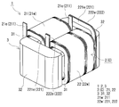
- FIG. 1 is an overall perspective view showing an outline of a reactor according to Embodiment 1.
- FIG. It is a top view which shows the outline of the reactor which concerns on Embodiment 1.
- FIG. 1 is an overall perspective view showing an outline of a reactor according to Embodiment 1.
- FIG. It is a top view which shows the outline of the reactor which concerns on Embodiment 1.
- FIG. 1 is an overall perspective view showing an outline of a reactor according to Embodiment 1.
- FIG. It is a top view which shows the outline of the reactor which concerns on Embodiment 1.
- an object is to provide a coil in which a pair of winding portions satisfy a specific heat generation characteristic relationship.
- the reactor of the present disclosure has a low loss.
- the pair of winding portions provided in the conventional coil are uniformly cooled when the windings have the same cross-sectional area and the same number of turns, and therefore the cooling performance of the cooling member is substantially uniform.
- the cooling member include an object to be installed such as a cooling base, and a fluid refrigerant that is circulated (for example, ATF: Automatic Transmission Fluid).
- ATF Automatic Transmission Fluid
- the present inventor when cooled by a cooling member with biased cooling performance, in order to uniformly cool a pair of winding parts, one winding part is less likely to generate heat than the other winding part.
- the number of wires constituting each winding part is made different from each other, and the winding of one winding part and the winding of the other winding part satisfy a specific cross-sectional area relationship, It was found that the heat generation characteristics of the winding part can be made different from each other.
- a pair of winding parts can be cooled equally by arrange
- a coil according to an aspect of the present invention is A first winding portion formed by spirally winding a first winding including at least one element wire; A second winding having a plurality of strands electrically connected to the first winding portion and spirally wound, and having an axis parallel to the axial direction of the first winding portion.
- Each strand included in the second winding is juxtaposed along the axial direction of the second winding part,
- the number of strands included in the second winding is greater than the number of strands included in the first winding
- the cross-sectional area of the second winding is greater than or equal to the cross-sectional area of the first winding;
- the cross-sectional area of the strand included in the second winding is equal to or less than the cross-sectional area of the strand included in the first winding.
- the first winding part tends to generate heat and the second winding part hardly generates heat. Satisfy the relationship. This is because the second winding part can easily reduce at least one of the direct current resistance and the alternating current resistance as compared with the first winding part, and can suppress heat generation associated with these resistances.
- the DC resistance of the second winding part is the same as the DC resistance of the first winding part
- the AC resistance of the second winding part is easier to reduce than the AC resistance of the first winding part. This is because the cross-sectional area of the strands included in the second winding is less than the cross-sectional area of the strands included in the first winding, so that an increase in AC resistance due to the skin effect can be suppressed.
- the AC resistance of the second winding portion is the AC resistance of the first winding portion.
- the direct current resistance of the second winding part is easier to reduce than the direct current resistance of the first winding part. This is because the cross-sectional area of the second winding is greater than the cross-sectional area of the first winding.
- the direct current resistance and alternating current resistance of the second winding part are easier to reduce than the direct current resistance and alternating current resistance of the first winding part, respectively.
- the reduction of the AC resistance of the second winding part is particularly effective when used at high frequencies.
- the relationship of the specific heat generation characteristic is satisfied as described above, it can be suitably used for a reactor cooled by a cooling member having a biased cooling performance.
- the first winding part and the second winding part are arranged by arranging the first winding part on the cooling member high cooling performance side and the second winding part on the cooling member cooling performance low side. This is because the maximum temperature of the coil can be reduced.
- it is suitable for use of a reactor that is used at a high frequency and is cooled by a cooling member having a biased cooling performance.
- a low-loss reactor can be constructed.
- the difference between the axial length of the first winding portion and the axial length of the second winding portion is the axial length of the first winding portion. 10% or less.
- the axial length of a 1st winding part and a 2nd winding part is small, the axial length of a 1st winding part and a 2nd winding part, and a magnetic core Among these, if the lengths of the pair of inner core portions where the first winding portion and the second winding portion are arranged are substantially the same, it is easy to construct a reactor with little dead space.
- the wire included in the first winding and the conductor wire of the wire included in the second winding are rectangular wires, and the wire included in the first winding It is mentioned that the width
- the conductor wire of the strand contained in each winding is a flat wire, and the width
- a reactor according to an aspect of the present invention is A reactor comprising a coil and a magnetic core on which the coil is disposed,
- the coil is the coil according to any one of (1) to (3) above.
- the second winding part can be cooled even when the cooling performance of the cooling member that cools the coil is biased.
- the first winding part and the second winding part can be cooled uniformly and the maximum temperature of the coil can be reduced. Because. Moreover, since the maximum temperature of the coil can be reduced, the choice of the material of the peripheral member of the coil can be expanded.
- Embodiment 1 ⁇ coil ⁇
- a coil C according to the first embodiment will be described with reference to FIGS.
- the coil C includes a pair of first and second winding parts 21 and 22.
- This coil C typically constitutes a coil 2 disposed on the outer periphery of a magnetic core 3 (inner core portion 31) provided in a reactor 1 (described later) (FIG. 1).
- One of the features of the coil C is that the number of wires included in the windings 21w and 22w of the winding parts 21 and 22 is different from each other and that the coil C is included in the first winding 21w of the first winding part 21.
- the element wire and the element wire included in the second winding 22w of the second winding portion 22 are in a point satisfying a specific cross-sectional area relationship.
- the reactor 1 is constructed by assembling the coil 2 to the magnetic core 3, the installation target side when the reactor 1 is installed on the installation target such as a cooling base for cooling the coil 2, and the opposite side of the installation target is up Will be described.
- the first winding portion 21 is a hollow cylindrical body formed by spirally winding a first winding 21w including at least one strand 211.
- the number of the strands 211 included in the first winding 21w may be singular as long as the relationship of “the number of strands included in the first winding 21w ⁇ the number of strands included in the second winding 22w” is satisfied. There may be multiple.
- the first winding 21w is spirally formed so that the strands are arranged in parallel along the axial direction of the first winding portion 21. Wind.
- the first winding 21 w is composed of one strand 211.
- the second winding part 22 is a hollow cylindrical body formed by spirally winding a second winding 22 w including a plurality of strands 221 and 222.
- the number of the wires 221 and 222 of the second winding 22w is two here, but may be three or more.
- the strands 221 and 222 of the second winding 22 w are arranged in parallel along the axial direction of the second winding portion 22. That is, the strands 221 and 222 are alternately arranged along the axial direction of the second winding portion 22.
- the second winding 22 w is composed of two strands 221 and 222.
- the first winding part 21 and the second winding part 22 are electrically connected in series.
- the conductors of the strands 221 and 222 of the second winding 22w are insulated except for end portions 221e and 222e (described later) on one end side and the other end side.
- Both winding parts 21 and 22 are arranged side by side (in parallel) so that the respective axial directions are parallel to each other.
- the end surface shape of each winding part 21 and 22 can be selected suitably, and is made into the shape which rounded the corner
- a coated wire having an insulating coating such as enamel (typically polyamideimide) on the outer periphery of the conductor wire can be used.
- the conductor wire include a flat wire and a round wire made of a conductive material such as copper, aluminum, or an alloy thereof.
- covered rectangular wires are used for the strands 211, 221, and 222 of the windings 21w and 22w, and the winding portions 21 and 22 are edgewise coils obtained by edgewise winding the covered rectangular wires.
- the cross-sectional areas of the first winding 21w and the second winding 22w are “(the cross-sectional area of the first winding 21w) ⁇ (the cross-sectional area of the second winding 22w)” and “(the element of the first winding 21w).
- the cross-sectional area of the first winding 21w means the cross-sectional area of one strand 211 when the number of the strands 211 of the first winding 21w is 1, and when the number of the strands 211 is plural, The total cross-sectional area of multiple strands.
- the cross-sectional area of the second winding 22w is the total cross-sectional area of the plurality of strands 221 and 222.
- the sectional area of the strands 211 of the first winding 21w means the sectional area of one strand 211, and the number of the strands 211 is In the case of multiple, it refers to the cross-sectional area of each strand.
- the cross-sectional areas of the strands may be different from each other but are preferably the same.
- the cross-sectional area of the wires 221 and 222 of the second winding 22w refers to the cross-sectional area of each of the wires 221 and 222.
- the cross-sectional areas of the wires 221 and 222 of the second winding 22w may be different from each other, but are preferably the same.
- cross-sectional area of the strand of the first winding 21w is different and the cross-sectional area of each strand of the second winding 22w is different
- “(cross-sectional area of the strand of the first winding 21w) ⁇ means "(minimum sectional area of the strands of the first winding 21w) ⁇ (maximum sectional area of the strands of the second winding 22w)”.
- the first winding part 21 When the coil C satisfies this relationship, when the heat generation characteristics of the first winding part 21 and the second winding part 22 are compared, the first winding part 21 easily generates heat, and the second winding part 22 generates heat. It satisfies the relationship of specific heat generation characteristics that it is difficult to do. This is because the second winding part 22 can easily reduce at least one of the direct current resistance and the alternating current resistance as compared with the first winding part 21, and can suppress heat generation associated with these resistances. Therefore, when the heat generation characteristics of the first winding part 21 and the second winding part 22 are compared, the first winding part 21 that is more likely to generate heat is disposed on the side of the cooling member (here, the cooling base) that has a higher cooling performance. And if the 2nd winding part 22 which is hard to generate
- the cross-sectional area of the first winding 21w and the cross-sectional area of the second winding 22w can be made the same. That is, the cross-sectional area of the strands 221 and 222 of the second winding 22w is less than the cross-sectional area of the strand 211 of the first winding 21w.
- the DC resistance of the second winding part 22 is the same as the DC resistance of the first winding part 21, but the AC resistance of the second winding part 22 is equal to the AC resistance of the first winding part 21. It is easy to reduce compared.
- the AC resistance of the second winding part 22 is the same as the AC resistance of the first winding part 21, but the DC resistance of the second winding part 22 is compared with the DC resistance of the first winding part 21. It is easy to reduce.
- the cross-sectional area of the second winding 22w is greater than the cross-sectional area of the first winding 21w, and the cross-sectional area of the strands 221 and 222 of the second winding 22w is the cross-sectional area of the strand 211 of the first winding 21w. It is preferable to satisfy less than. Then, the direct current resistance and the alternating current resistance of the second winding part 22 are easier to reduce than the direct current resistance and the alternating current resistance of the first winding part 21, respectively.
- the reduction of the AC resistance of the second winding part 22 is particularly effective when used at high frequencies.
- the relationship between the cross-sectional areas of the first winding 21w and the second winding 22w can be appropriately selected according to the number of turns of the winding portions 21 and 22 and the axial lengths L1 and L2.
- the width W1 of the first winding 21w refers to the width of one strand 211 when the number of strands is one, and refers to the width of each strand when the number of strands is plural.
- the widths of the strands may be different from each other but are preferably the same.
- the width W2 of the second winding 22w is the width of each of the strands 221 and 222.
- the widths of the strands 221 and 222 of the second winding 22w may be different from each other, but are preferably the same.
- the widths W1 and W2 refer to the lengths along the parallel direction of the winding portions 21 and 22 in the windings 21w and 22w, respectively.
- the width W1 of the first winding 21w and the width W2 of the second winding 22w are equal when the reactor 1 is constructed by combining the coil C and the magnetic core 3 and the first winding portion 21 and the second winding.
- the sizes of the first winding 21w and the second winding 22w preferably satisfy the relationship “(thickness T1 of the first winding 21w) ⁇ (thickness T2 of the second winding 22w)”.
- the thickness T1 of the first winding 21w means the thickness of one strand 211 when the number of the strands 211 is one, and the thickness of each strand when the number of the strands 211 is plural. .
- the thicknesses of the strands may be different from each other, but are preferably the same.
- the thickness T2 of the second winding 22w refers to the thickness of each of the strands 221 and 222.
- the thicknesses of the wires 221 and 222 of the second winding 22w may be different from each other, but are preferably the same.
- the thicknesses T1 and T2 refer to the lengths along the axial direction of the winding portions 21 and 22 in the windings 21w and 22w, respectively.
- the relationship between the thickness T1 of the first winding 21w and the thickness T2 of the second winding 22w can be appropriately selected according to the number of turns of both the winding portions 21 and 22 and the axial lengths L1 and L2.
- the total number of turns of both winding parts 21 and 22 can be appropriately selected according to the desired inductance.
- the number of turns of each winding part 21 and 22 is appropriately selected according to the required inductance.
- the number of turns of the first winding part 21 refers to the number of turns of the first winding 21w. That is, when the number of strands is one, it means the number of turns of one strand 211. When the number of strands is plural, it is not the total number of turns of a plurality of strands, but one of the strands. Say the number of turns of the line.
- the number of turns of the wire 211 of the first winding 21w is the same when there are a plurality of wires 211.
- the number of turns of the second winding part 22 refers to the number of turns of the second winding 22w. That is, it is not the total number of turns of the strands 221 and 222 of the second winding 22w, but the number of turns of one strand 221 (222) included in the second winding 22w (the number of turns of the second winding 22w). ) For example, when the number of turns of the wires 221 and 222 of the second winding 22w is “n times (n: positive integer)”, the number of turns of the second winding part 22 is not “2n times”. “N times”.
- the number of turns of the second winding part 22 is often smaller than the number of turns of the first winding part 21, but it can be the same as the number of turns of the first winding part 21 or the number of turns of the first winding part 21. Or more than a number.
- the difference in the number of turns between the first winding part 21 and the second winding part 22 is due to the condition of energizing the coil C and the cooling performance for the winding parts 21 and 22 of the cooling member (cooling base) that cools the coil C. It can be appropriately selected depending on the difference.
- the axial lengths (hereinafter simply referred to as axial lengths) L1 and L2 of the winding portions 21 and 22 can be appropriately selected according to a desired inductance (FIG. 2). It is preferable that the axial length L1 of the first winding part 21 and the axial length L2 of the second winding part 22 are substantially the same. The axial length L1 of the first winding portion 21 and the axial length L2 of the second winding portion 22 are substantially equal to each other. The difference from L2 means that 10% or less of the axial length L1 of the first winding part 21 is satisfied.
- the reactor 1 which does not exist substantially can be constructed
- the difference between the axial length L1 of the first winding part 21 and the axial length L2 of the second winding part 22 preferably satisfies 5% or less.
- End portions 21e, 221e, and 222e on one end side in the axial direction of each winding portion 21 and 22 are extended upward, and the insulating coating at the tip is peeled off.
- a terminal member (not shown) is connected to the exposed conductor.
- the ends 221e and 222e on one end side of the second winding 22w are electrically connected.
- the coil C is connected to an external device (not shown) such as a power source for supplying power to the coil C through this terminal member.
- the end portions 21e, 221e, and 222e on the other end side in the axial direction (the right side in FIG. 1 and the upper side in FIG.
- each winding portion 21 and 22 are electrically connected to each other.
- This electrical connection may be performed by directly connecting the end portion 21e and the end portions 221e and 222e as in this example, or is independent of the first winding portion 21 and the second winding portion 22. You may connect via the connecting member to do.
- a short conductor especially a winding
- the ends 221e and 222e on the other end side of the second winding 22w are electrically connected in the same manner as the one end side.
- the ends 221e and 222e of the second winding 22w are bent as in this example.
- the first winding 21w may be configured by extending toward the end 21e and connecting the end 21e and the ends 221e and 222e.
- edge-wise bending can be used as a method of bending the second winding 22w on the end portions 221e and 222e side as in the case of the turn forming portion.
- the second winding 22w is easy to bend because the thickness T2 of the wires 221 and 222 is smaller than the thickness T1 of the first winding 21w (wire 211).
- the ends 21e of the first winding 21w may be bent and extended toward the ends 221e and 222e of the second winding 22w.
- the bending method may be edgewise bending or flatwise bending, and the windings are partially overlapped with each other in the thickness direction at the turn-back position.
- the extending direction of one winding 21w may be changed by 90 °.
- the thickness T1 of the strand 211 is larger than the thickness T2 of the strands 221 and 222 of the second winding 22w, but the number of the strands 211 is one here.
- connection member Since there are fewer than the strands 221 and 222 of the two windings 22w, it is easy to bend. On the other hand, when connecting via the said connection member, using the same wire as the 1st coil
- connection between the end 21e and the ends 221e and 222e, the connection between the end 21e and the ends 221e and 222e and the connection member, and the connection between the ends 221e and 222e are welding (for example, TIG welding), Can be done by soldering or crimping.
- the strands 211, 221, and 222 of the windings 21w and 22w those having a heat fusion layer made of a heat fusion resin can be used.
- a heat fusion layer made of a heat fusion resin can be used.
- the heat-sealing resin portion is interposed between the turns, the turns do not substantially deviate from each other, and the coil C is hardly deformed.
- the heat-sealing resin constituting the heat-sealing layer include thermosetting resins such as epoxy resins, silicone resins, and unsaturated polyesters.
- the first winding part 21 can be produced by preparing a first winding 21w including at least one (here, one) strand 211 and spirally winding the first winding 21w.
- the second winding part 22 is produced by preparing a second winding 22w including a plurality of (two in this case) strands 221, 222 and winding the plurality of strands 221, 222 simultaneously.
- It may be performed by combining a wound component obtained by individually winding a plurality of strands 221 and 222.
- a plurality of strands 221 and 222 are overlapped along the winding direction and simultaneously wound spirally.
- the combination of the individually wound winding parts first, the two strands 221 and 222 are spirally wound to produce two wound parts. At this time, the pitch of each winding component is adjusted so that each turn of the other winding component fits between each turn of one winding component. And it fits together so that each turn of the other winding components may fit between each turn of one winding component.
- the cooling is performed by a cooling member having a biased cooling performance. It can utilize suitably for the reactor 1 made.
- the coil C described above can be used for the coil 2 of the reactor 1 shown in FIGS.
- the reactor 1 includes the coil 2 and the magnetic core 3 on which the coil 2 is disposed.
- the coil 2 is composed of the coil C described above.
- the coil 2 includes the first winding part 21 and the second winding part 22 described above. Both winding parts 21 and 22 are arranged in a state of being lined up side by side (parallel) so that the respective axial directions are parallel.
- the coil 2 is cooled by a cooling member (not shown). Although the cooling member will be described in detail later, in this example, a cooling base including a first cooling part that cools the first winding part 21 and a second cooling part that cools the second winding part 22 may be mentioned.
- the cooling performance of the first cooling unit is higher than the cooling performance of the second cooling unit.
- the winding form of both winding parts 21 and 22 arrange
- FIG. 1st winding part 21 and the 2nd winding part 22 are cooled equally, and it can be made hard to produce the temperature difference of both the winding parts 21 and 22.
- the magnetic core 3 includes a pair of inner core portions 31 disposed inside the winding portions 21 and 22 and a pair of outer core portions 32 that are not disposed on the coil 2 and project (expose) from the coil 2. .
- the magnetic core 3 is formed in an annular shape with an outer core portion 32 disposed so as to sandwich the inner core portion 31 that is spaced apart, and the end surface of the inner core portion 31 and the inner end surface of the outer core portion 32 are in contact with each other.
- the inner core portion 31 and the outer core portion 32 form a closed magnetic circuit when the coil 2 is excited.
- this magnetic core 3 a known one can be used.
- Each inner core portion 31 may be configured by a stacked body in which a plurality of columnar core pieces and gap portions made of a material having a relative permeability smaller than that of the core pieces are alternately stacked. Instead, it may be constituted by one columnar core piece having a substantially full length in the axial direction of the winding portions 21 and 22.
- the lengths along the axial direction of the coil 2 in the pair of inner core portions 31 are the same as each other, and are substantially the same as the axial length of the coil 2.
- the shape of the inner core portion 31 is preferably a shape that matches the inner peripheral shape of the winding portions 21 and 22.
- the shape of the inner core part 31 is a rectangular parallelepiped shape having a length in substantially the entire axial direction of the winding parts 21 and 22, and the inner peripheral surfaces of the winding parts 21 and 22 with rounded corners. It is rounded along.
- the shape of the outer core portion 32 is a columnar body having a substantially dome-shaped upper and lower surfaces in this example.
- the height of the outer core portion 32 is larger than that of the inner core portion 31, the upper surface of the outer core portion 32 is substantially flush with the upper surface of the inner core portion 31, and the lower surface of the outer core portion 32 is the lower surface of the coil 2. It is preferable that they are substantially flush with each other.
- the height of the outer core portion 32 refers to the length along the vertical direction.
- the core piece of the inner core portion 31 and the outer core portion 32 are a compact molded body obtained by compression-molding soft magnetic powder, and a composite material (molded and cured body) in which the soft magnetic powder and the resin are solidified (cured). Etc. are available.
- the particles constituting the soft magnetic powder are metal particles made of soft magnetic metals such as iron group metals such as pure iron and iron-based alloys (Fe-Si alloys, Fe-Ni alloys, etc.), and phosphoric acid around the metal particles.
- metal particles made of soft magnetic metals such as iron group metals such as pure iron and iron-based alloys (Fe-Si alloys, Fe-Ni alloys, etc.), and phosphoric acid around the metal particles.
- examples thereof include coated particles having an insulating coating composed of salt or the like, and particles made of a nonmetallic material such as ferrite.
- the average particle size of the soft magnetic powder examples include 1 ⁇ m or more and 1000 ⁇ m or less, and further 10 ⁇ m or more and 500 ⁇ m or less.
- This average particle size can be obtained by obtaining a cross-sectional image with an SEM (scanning electron microscope) and analyzing it using commercially available image analysis software.
- the equivalent circle diameter is the particle diameter of the soft magnetic particles.
- the resin of the composite material examples include thermosetting resins such as epoxy resin, phenol resin, silicone resin, and urethane resin, polyphenylene sulfide (PPS) resin, polyamide (PA) resin (for example, nylon 6, nylon 66, nylon 9T). Etc.), thermoplastic polymers such as liquid crystal polymer (LCP), polyimide resin and fluororesin, room temperature curable resin, low temperature curable resin, and the like.
- thermosetting resins such as epoxy resin, phenol resin, silicone resin, and urethane resin
- PPS polyphenylene sulfide
- PA polyamide
- LCP liquid crystal polymer
- polyimide resin and fluororesin room temperature curable resin
- room temperature curable resin low temperature curable resin
- BMC Bulk molding compound in which calcium carbonate or glass fiber is mixed with unsaturated polyester, millable silicone rubber, millable urethane rubber, or the like can be used.
- the content of the resin in the composite material is 20% by volume or more and 70% by volume or less.
- the lower the resin content that is, the higher the soft magnetic powder content, the higher the saturation magnetic flux density and the better the heat dissipation.
- the upper limit of the resin content is 50% by volume or less, and further 45% by volume. Hereinafter, it can be made 40 volume% or less. If the resin content is high to some extent, that is, if the soft magnetic powder content is low to some extent, when filling the raw material of the composite material (raw material mixture) into the mold, it is easy to fill the mold. Improvement of manufacturability can be expected, and the lower limit of the resin content can be 25% by volume or more, and further 30% by volume or more.
- the above composite material can contain filler powder made of nonmagnetic material such as ceramics such as alumina and silica, in addition to soft magnetic powder and resin. In this case, for example, heat dissipation can be improved.
- filler powder made of nonmagnetic material such as ceramics such as alumina and silica
- heat dissipation can be improved.
- the content of the filler powder in the composite material include 0.2% by mass to 20% by mass, 0.3% by mass to 15% by mass, and 0.5% by mass to 10% by mass.
- a cooling member cools the coil 2, and a cooling base provided with the 1st cooling part and the 2nd cooling part from which cooling performance differs as mentioned above in this example is mentioned.
- This cooling base is an installation target of the reactor 1.
- the first cooling unit and the second cooling unit may be a plurality of members having different cooling performances. However, although the cooling unit is a series of cooling plates, depending on the region, the refrigerant flow path is only part of the cooling plate. There may be a difference in cooling performance. The difference in the cooling performance between the first cooling unit and the second cooling unit may be a difference that can cool the first winding unit 21 and the second winding unit 22 uniformly.
- the ratio between the cooling performance (W) of the first cooling section and the cooling performance (W) of the second cooling section may satisfy about 2: 1 to 20: 1.
- examples of the cooling member include fluid refrigerant (for example, FET) that is circulated and supplied.
- the fact that the cooling performance of the fluid refrigerant is uneven means that, for example, the supply amounts to the first winding part 21 and the second winding part 22 are different.
- cooling is performed by applying the fluid refrigerant to the coil 2
- positions in a location there exists a difference in the contact state with the fluid refrigerant
- Reactor 1 is a variety of converters such as in-vehicle converters (typically DC-DC converters) and air conditioner converters installed in vehicles such as hybrid vehicles, plug-in hybrid vehicles, electric vehicles, and fuel cell vehicles. It can utilize suitably for the component of a converter.
- in-vehicle converters typically DC-DC converters
- air conditioner converters installed in vehicles such as hybrid vehicles, plug-in hybrid vehicles, electric vehicles, and fuel cell vehicles. It can utilize suitably for the component of a converter.
Landscapes
- Engineering & Computer Science (AREA)
- Power Engineering (AREA)
- Coils Of Transformers For General Uses (AREA)
Abstract
少なくとも1本の素線を含む第一巻線を螺旋状に巻回してなる第一巻回部と、前記第一巻回部と電気的に接続される複数本の素線を含む第二巻線を螺旋状に巻回してなり、前記第一巻回部の軸方向に平行な軸を有する第二巻回部とを備え、前記第二巻線に含まれる各素線は、前記第二巻回部の軸方向に沿って並列され、前記第二巻線に含まれる素線の本数が前記第一巻線に含まれる素線の本数よりも多く、前記第二巻線の断面積が前記第一巻線の断面積以上であり、前記第二巻線に含まれる素線の断面積が前記第一巻線に含まれる素線の断面積以下であるコイル。
Description
本発明は、コイル、及びリアクトルに関する。
本出願は、2017年2月22日付の日本国出願の特願2017-031433に基づく優先権を主張し、前記日本国出願に記載された全ての記載内容を援用するものである。
本出願は、2017年2月22日付の日本国出願の特願2017-031433に基づく優先権を主張し、前記日本国出願に記載された全ての記載内容を援用するものである。
電圧の昇圧動作や降圧動作を行う回路の部品として、特許文献1のリアクトルが知られている。このリアクトルは、一対のコイル素子(巻回部)を有するコイルと、コイルに組み合わされる環状の磁性コアとを備える。各コイル素子は、互いに同一の巻き数で形成され、各軸方向が平行するように横並びに並列されている(明細書0020,図1)。
本開示に係るコイルは、
少なくとも1本の素線を含む第一巻線を螺旋状に巻回してなる第一巻回部と、
前記第一巻回部と電気的に接続される複数本の素線を含む第二巻線を螺旋状に巻回してなり、前記第一巻回部の軸方向に平行な軸を有する第二巻回部とを備え、
前記第二巻線に含まれる各素線は、前記第二巻回部の軸方向に沿って並列され、
前記第二巻線に含まれる素線の本数が前記第一巻線に含まれる素線の本数よりも多く、
前記第二巻線の断面積が前記第一巻線の断面積以上であり、
前記第二巻線に含まれる素線の断面積が前記第一巻線に含まれる素線の断面積以下である。
少なくとも1本の素線を含む第一巻線を螺旋状に巻回してなる第一巻回部と、
前記第一巻回部と電気的に接続される複数本の素線を含む第二巻線を螺旋状に巻回してなり、前記第一巻回部の軸方向に平行な軸を有する第二巻回部とを備え、
前記第二巻線に含まれる各素線は、前記第二巻回部の軸方向に沿って並列され、
前記第二巻線に含まれる素線の本数が前記第一巻線に含まれる素線の本数よりも多く、
前記第二巻線の断面積が前記第一巻線の断面積以上であり、
前記第二巻線に含まれる素線の断面積が前記第一巻線に含まれる素線の断面積以下である。
本開示に係るリアクトルは、
コイルと、前記コイルが配置される磁性コアとを備えるリアクトルであって、
前記コイルは、上記本開示に係るコイルである。
コイルと、前記コイルが配置される磁性コアとを備えるリアクトルであって、
前記コイルは、上記本開示に係るコイルである。
[本開示が解決しようとする課題]
リアクトルの設置状況によっては、両巻回部の冷却特性が偏る虞があり、一対の巻回部の発熱特性に更なる改善の余地があった。
リアクトルの設置状況によっては、両巻回部の冷却特性が偏る虞があり、一対の巻回部の発熱特性に更なる改善の余地があった。
そこで、一対の巻回部が特定の発熱特性の関係を満たすコイルを提供することを目的の一つとする。
また、上記コイルを備えるリアクトルを提供することを目的の一つとする。
[本開示の効果]
本開示のコイルは、一対の巻回部が特定の発熱特性の関係を満たす。
本開示のコイルは、一対の巻回部が特定の発熱特性の関係を満たす。
本開示のリアクトルは、低損失である。
《本発明の実施形態の説明》
従来のコイルに備わる一対の巻回部は、その巻線が互いに同一断面積でターン数が互いに同じであるため、冷却部材の冷却性能に偏りが実質的にないと均一に冷却される。冷却部材とは、冷却ベース等の設置対象や、循環供給される流体冷媒(例えば、ATF:Automatic Transmission Fluid)などが挙げられる。しかし、リアクトルの設置状況の制約などから、冷却部材の冷却特性に偏りがあると、一方の巻回部が他方の巻回部に比べて冷却され難い。そうすると、一方の巻回部が他方の巻回部に比べて高温になり、リアクトルの損失が大きくなる。
従来のコイルに備わる一対の巻回部は、その巻線が互いに同一断面積でターン数が互いに同じであるため、冷却部材の冷却性能に偏りが実質的にないと均一に冷却される。冷却部材とは、冷却ベース等の設置対象や、循環供給される流体冷媒(例えば、ATF:Automatic Transmission Fluid)などが挙げられる。しかし、リアクトルの設置状況の制約などから、冷却部材の冷却特性に偏りがあると、一方の巻回部が他方の巻回部に比べて冷却され難い。そうすると、一方の巻回部が他方の巻回部に比べて高温になり、リアクトルの損失が大きくなる。
本発明者は、冷却性能に偏りがある冷却部材で冷却される場合に、一対の巻回部を均等に冷却させるには、一方の巻回部が他方の巻回部に比べて発熱し難いという特定の発熱特性の関係を満たせばよいのではないかと考え、両巻回部の発熱特性を互いに異ならせることを鋭意検討した。その結果、各巻回部を構成する素線の数を互いに異ならせると共に、一方の巻回部の巻線と他方の巻回部の巻線とが特定の断面積の関係を満たすことで、両巻回部の発熱特性を互いに異ならせることができるとの知見を得た。そうすれば、発熱特性の大きい巻回部を冷却性能の高い側に、発熱特性の小さい巻回部を冷却性能の低い側に配置することで、一対の巻回部を均等に冷却できる。本発明は、これらの知見に基づくものである。最初に本発明の実施態様を列記して説明する。
(1)本発明の一形態に係るコイルは、
少なくとも1本の素線を含む第一巻線を螺旋状に巻回してなる第一巻回部と、
前記第一巻回部と電気的に接続される複数本の素線を含む第二巻線を螺旋状に巻回してなり、前記第一巻回部の軸方向に平行な軸を有する第二巻回部とを備え、
前記第二巻線に含まれる各素線は、前記第二巻回部の軸方向に沿って並列され、
前記第二巻線に含まれる素線の本数が前記第一巻線に含まれる素線の本数よりも多く、
前記第二巻線の断面積が前記第一巻線の断面積以上であり、
前記第二巻線に含まれる素線の断面積が前記第一巻線に含まれる素線の断面積以下である。
少なくとも1本の素線を含む第一巻線を螺旋状に巻回してなる第一巻回部と、
前記第一巻回部と電気的に接続される複数本の素線を含む第二巻線を螺旋状に巻回してなり、前記第一巻回部の軸方向に平行な軸を有する第二巻回部とを備え、
前記第二巻線に含まれる各素線は、前記第二巻回部の軸方向に沿って並列され、
前記第二巻線に含まれる素線の本数が前記第一巻線に含まれる素線の本数よりも多く、
前記第二巻線の断面積が前記第一巻線の断面積以上であり、
前記第二巻線に含まれる素線の断面積が前記第一巻線に含まれる素線の断面積以下である。
上記の構成によれば、第一巻回部と第二巻回部の発熱特性を比較すると、第一巻回部が発熱し易く、第二巻回部が発熱し難いという特定の発熱特性の関係を満たす。第二巻回部は、第一巻回部に比較して、直流抵抗及び交流抵抗の少なくとも一方を小さくし易いため、これらの抵抗に伴う発熱を抑制できるからである。
具体的には、第一巻線の断面積と第二巻線の断面積とが同じ場合、第二巻回部の直流抵抗は、第一巻回部の直流抵抗と同じであるが、第二巻回部の交流抵抗は、第一巻回部の交流抵抗に比較して低減し易い。これは、第二巻線に含まれる素線の断面積が第一巻線に含まれる素線の断面積未満であるため、表皮効果による交流抵抗の増加を抑制できるからである。一方、第一巻線に含まれる素線の断面積と第二巻線に含まれる素線の断面積とが同じ場合、第二巻回部の交流抵抗は第一巻回部の交流抵抗と同じであるが、第二巻回部の直流抵抗は、第一巻回部の直流抵抗に比較して低減し易い。これは、第二巻線の断面積が第一巻線の断面積超であるからである。即ち、第二巻線の断面積が第一巻線の断面積超で、かつ第二巻線に含まれる素線の断面積が第一巻線に含まれる素線の断面積未満の場合、第二巻回部の直流抵抗及び交流抵抗はそれぞれ、第一巻回部の直流抵抗及び交流抵抗に比較して低減し易い。第二巻回部の交流抵抗の低減は、高周波で利用される場合に特に効果的である。
上記の構成によれば、上述のように上記特定の発熱特性の関係を満たすため、冷却性能に偏りのある冷却部材により冷却されるリアクトルに好適に利用できる。第一巻回部を冷却部材の冷却性能の高い側に配置し、第二巻回部を冷却部材の冷却性能の低い側に配置することで、第一巻回部と第二巻回部とを均等に冷却できて、コイルの最高温度を低減できるからである。特に、高周波で利用されて、冷却性能に偏りのある冷却部材により冷却されるリアクトルの利用に好適である。このようにコイルの最高温度を低減できるため、低損失なリアクトルを構築できる。
(2)上記コイルの一形態として、前記第一巻回部の軸方向の長さと前記第二巻回部の軸方向の長さとの差が、前記第一巻回部の軸方向の長さの10%以下であることが挙げられる。
上記の構成によれば、第一巻回部と第二巻回部の軸方向の長さの差が小さいため、第一巻回部及び第二巻回部の軸方向の長さと、磁性コアのうち、第一巻回部及び第二巻回部が配置される一対の内側コア部の長さとを実質的に同一とすれば、デッドスペースの少ないリアクトルを構築し易い。
(3)上記コイルの一形態として、前記第一巻線に含まれる素線及び第二巻線に含まれる素線の導体線が平角線であり、前記第一巻線に含まれる素線と前記第二巻線に含まれる素線の幅が同じであることが挙げられる。
上記の構成によれば、各巻線に含まれる素線の導体線が平角線であり、各巻線に含まれる素線の幅が同じであることで、このコイルを一対の内側コア部と組み合わせた際、第一巻回部と第二巻回部の幅や高さのばらつきの少ないリアクトルを構築できる。
(4)本発明の一形態に係るリアクトルは、
コイルと、前記コイルが配置される磁性コアとを備えるリアクトルであって、
前記コイルは、上記(1)から上記(3)のいずれか1つに記載のコイルである。
コイルと、前記コイルが配置される磁性コアとを備えるリアクトルであって、
前記コイルは、上記(1)から上記(3)のいずれか1つに記載のコイルである。
上記の構成によれば、損失を低減できる。発熱し難い第二巻回部と発熱し易い第一巻回部とを有するコイルを備えることで、このコイルを冷却する冷却部材の冷却性能に偏りがある場合でも、第二巻回部を冷却性能の低い側に配置し、第一巻回部を冷却性能の高い側に配置することで、第一巻回部と第二巻回部とを均一に冷却できてコイルの最高温度を低減できるからである。また、コイルの最高温度を低減できるため、コイルの周辺部材の材質の選択肢を広げられる。
《本発明の実施形態の詳細》
本発明の実施形態の詳細を、以下に図面を参照しつつ説明する。図中の同一符号は同一名称物を示す。実施形態での説明は、コイル、リアクトルの順に行う。
本発明の実施形態の詳細を、以下に図面を参照しつつ説明する。図中の同一符号は同一名称物を示す。実施形態での説明は、コイル、リアクトルの順に行う。
《実施形態1》
〔コイル〕
図1,図2を参照して、実施形態1に係るコイルCを説明する。コイルCは、一対の第一・第二巻回部21、22を備える。このコイルCは、代表的にはリアクトル1(後述)に備わる磁性コア3(内側コア部31)の外周に配置されるコイル2を構成する(図1)。このコイルCの特徴の一つは、各巻回部21,22の巻線21w,22wに含まれる素線の数を互いに異ならせると共に、第一巻回部21の第一巻線21wに含まれる素線と第二巻回部22の第二巻線22wに含まれる素線とが特定の断面積の関係を満たす点にある。ここでは、コイル2を磁性コア3に組み付けてリアクトル1を構築し、コイル2を冷却する冷却ベース等の設置対象にリアクトル1を設置した際の設置対象側を下、設置対象の反対側を上として説明する。
〔コイル〕
図1,図2を参照して、実施形態1に係るコイルCを説明する。コイルCは、一対の第一・第二巻回部21、22を備える。このコイルCは、代表的にはリアクトル1(後述)に備わる磁性コア3(内側コア部31)の外周に配置されるコイル2を構成する(図1)。このコイルCの特徴の一つは、各巻回部21,22の巻線21w,22wに含まれる素線の数を互いに異ならせると共に、第一巻回部21の第一巻線21wに含まれる素線と第二巻回部22の第二巻線22wに含まれる素線とが特定の断面積の関係を満たす点にある。ここでは、コイル2を磁性コア3に組み付けてリアクトル1を構築し、コイル2を冷却する冷却ベース等の設置対象にリアクトル1を設置した際の設置対象側を下、設置対象の反対側を上として説明する。
[第一巻回部・第二巻回部]
第一巻回部21は、少なくとも1本の素線211を含む第一巻線21wを螺旋状に巻回してなる中空の筒状体である。第一巻線21wに含まれる素線211の数は、「第一巻線21wに含まれる素線の数<第二巻線22wに含まれる素線の数」の関係を満たせば、単数でも複数でもよい。第一巻線21wに含まれる素線の数を複数本とする場合、各素線は、第一巻回部21の軸方向に沿って並列するように、第一巻線21wを螺旋状に巻回する。ここでは、第一巻線21wは、1本の素線211からなる。一方、第二巻回部22は、複数本の素線221,222を含む第二巻線22wを螺旋状に巻回してなる中空の筒状体である。第二巻線22wの素線221,222の数は、ここでは2本であるが、3本以上でもよい。第二巻線22wの各素線221,222は、第二巻回部22の軸方向に沿って並列している。即ち、この各素線221,222は、第二巻回部22の軸方向に沿って交互に並んでいる。ここでは、第二巻線22wは、2本の素線221、222からなる。
第一巻回部21は、少なくとも1本の素線211を含む第一巻線21wを螺旋状に巻回してなる中空の筒状体である。第一巻線21wに含まれる素線211の数は、「第一巻線21wに含まれる素線の数<第二巻線22wに含まれる素線の数」の関係を満たせば、単数でも複数でもよい。第一巻線21wに含まれる素線の数を複数本とする場合、各素線は、第一巻回部21の軸方向に沿って並列するように、第一巻線21wを螺旋状に巻回する。ここでは、第一巻線21wは、1本の素線211からなる。一方、第二巻回部22は、複数本の素線221,222を含む第二巻線22wを螺旋状に巻回してなる中空の筒状体である。第二巻線22wの素線221,222の数は、ここでは2本であるが、3本以上でもよい。第二巻線22wの各素線221,222は、第二巻回部22の軸方向に沿って並列している。即ち、この各素線221,222は、第二巻回部22の軸方向に沿って交互に並んでいる。ここでは、第二巻線22wは、2本の素線221、222からなる。
第一巻回部21と第二巻回部22とは、電気的に直列に接続されている。第二巻線22wの素線221,222の導体同士は、一端側及び他端側の端部221e,222e(後述)を除き絶縁されている。両巻回部21,22の配置は、各軸方向が平行するように横並び(並列)した状態としている。各巻回部21,22の端面形状は、適宜選択でき、ここでは矩形枠の角部を丸めた形状としている。各巻線21w、22wの素線211,221,222は、導体線の外周にエナメル(代表的にはポリアミドイミド)などの絶縁被覆を備える被覆線を利用できる。導体線は、銅やアルミニウム、その合金といった導電性材料からなる平角線や丸線が挙げられる。ここでは、各巻線21w、22wの素線211,221,222に被覆平角線を用い、各巻回部21,22は被覆平角線をエッジワイズ巻きしたエッジワイズコイルとしている。
(断面積)
第一巻線21wと第二巻線22wの断面積は、「(第一巻線21wの断面積)≦(第二巻線22wの断面積)」、かつ「(第一巻線21wの素線211の断面積)≧(第二巻線22wの素線221,222の断面積)」の関係を満たす。第一巻線21wの断面積とは、第一巻線21wの素線211の数が1本の場合、1本の素線211の断面積を言い、素線211の数が複数の場合、複数本の素線の合計断面積を言う。第二巻線22wの断面積は、複数本の素線221,222の合計断面積を言う。第一巻線21wの素線211の断面積とは、第一巻線21wの素線211の数が1本の場合、1本の素線211の断面積を言い、素線211の数が複数の場合、各素線の断面積を言う。第一巻線21wの素線211が複数の場合、各素線の断面積はそれぞれ、異なっていてもよいが、同一とすることが好ましい。第二巻線22wの素線221,222の断面積とは、各素線221,222の断面積を言う。第二巻線22wの素線221,222の断面積はそれぞれ、異なっていてもよいが、同一とすることが好ましい。第一巻線21wの各素線の断面積が異なり、第二巻線22wの各素線の断面積が異なっている場合、「(第一巻線21wの素線の断面積)≧(第二巻線22wの素線221,222の断面積)」とは、「(第一巻線21wの素線の最小断面積)≧(第二巻線22wの素線の最大断面積)」を意味する。
第一巻線21wと第二巻線22wの断面積は、「(第一巻線21wの断面積)≦(第二巻線22wの断面積)」、かつ「(第一巻線21wの素線211の断面積)≧(第二巻線22wの素線221,222の断面積)」の関係を満たす。第一巻線21wの断面積とは、第一巻線21wの素線211の数が1本の場合、1本の素線211の断面積を言い、素線211の数が複数の場合、複数本の素線の合計断面積を言う。第二巻線22wの断面積は、複数本の素線221,222の合計断面積を言う。第一巻線21wの素線211の断面積とは、第一巻線21wの素線211の数が1本の場合、1本の素線211の断面積を言い、素線211の数が複数の場合、各素線の断面積を言う。第一巻線21wの素線211が複数の場合、各素線の断面積はそれぞれ、異なっていてもよいが、同一とすることが好ましい。第二巻線22wの素線221,222の断面積とは、各素線221,222の断面積を言う。第二巻線22wの素線221,222の断面積はそれぞれ、異なっていてもよいが、同一とすることが好ましい。第一巻線21wの各素線の断面積が異なり、第二巻線22wの各素線の断面積が異なっている場合、「(第一巻線21wの素線の断面積)≧(第二巻線22wの素線221,222の断面積)」とは、「(第一巻線21wの素線の最小断面積)≧(第二巻線22wの素線の最大断面積)」を意味する。
コイルCは、この関係を満たすことで、第一巻回部21と第二巻回部22の発熱特性を比較すると、第一巻回部21が発熱し易く、第二巻回部22が発熱し難いという特定の発熱特性の関係を満たす。第二巻回部22は、第一巻回部21に比較して、直流抵抗及び交流抵抗の少なくとも一方を小さくし易いため、これらの抵抗に伴う発熱を抑制できるからである。そのため、第一巻回部21と第二巻回部22の発熱特性を比較したとき、より発熱し易い第一巻回部21を冷却部材(ここでは冷却ベース)の冷却性能の高い側に配置し、より発熱し難い第二巻回部22を冷却部材(冷却ベース)の冷却性能の低い側に配置すれば、損失の少ないリアクトル1を構築し易い。
例えば、第一巻線21wの断面積と第二巻線22wの断面積の関係は、第一巻線21wの断面積と第二巻線22wの断面積とを同一とすることができる。即ち、第二巻線22wの素線221,222の断面積は、第一巻線21wの素線211の断面積未満である。この場合、第二巻回部22の直流抵抗は、第一巻回部21の直流抵抗と同じであるが、第二巻回部22の交流抵抗は、第一巻回部21の交流抵抗に比較して低減し易い。これは、第二巻線22wの素線221,222の断面積が第一巻線21wの素線211の断面積未満であることで表皮効果による交流抵抗の増加を抑制できるからである。また、第一巻線21wの素線211の断面積と第二巻線22wの素線221,222の断面積とを同一することができる。即ち、第二巻線22wの断面積は、第一巻線21wの断面積超である。この場合、第二巻回部22の交流抵抗は第一巻回部21の交流抵抗と同じであるが、第二巻回部22の直流抵抗は、第一巻回部21の直流抵抗に比較して低減し易い。特に、第二巻線22wの断面積が第一巻線21wの断面積超で、かつ第二巻線22wの素線221,222の断面積が第一巻線21wの素線211の断面積未満を満たすことが好ましい。そうすれば、第二巻回部22の直流抵抗及び交流抵抗はそれぞれ、第一巻回部21の直流抵抗及び交流抵抗に比較して低減し易い。第二巻回部22の交流抵抗の低減は、高周波で利用される場合に特に効果的である。第一巻線21wと第二巻線22wの断面積の関係は、各巻回部21,22のターン数及び軸長L1,L2に応じて適宜選択できる。
(サイズ)
第一巻線21wと第二巻線22wのサイズは、例えば「(第一巻線21wの幅W1)<(第二巻線22wの幅W2)」の関係を満たすように異なっていてもよいが、「(第一巻線21wの幅W1)=(第二巻線22wの幅W2)」の関係を満たすことが好ましい(図2)。第一巻線21wの幅W1とは、素線の数が1本の場合、1本の素線211の幅を言い、素線の数が複数の場合、各素線の幅を言う。第一巻線21wの素線211が複数の場合、各素線の幅はそれぞれ、異なっていてもよいが、同一とすることが好ましい。第二巻線22wの幅W2は、各素線221,222の幅を言う。第二巻線22wの素線221,222の幅はそれぞれ、異なっていても良いが、同一であることが好ましい。幅W1,W2とは、各巻線21w,22wにおいて、各巻回部21,22の並列方向に沿った長さを言う。第一巻線21wの幅W1と第二巻線22wの幅W2とが等しいとは、コイルCと磁性コア3とを組み合わせてリアクトル1を構築した際、第一巻回部21と第二巻回部22の幅及び高さのばらつきが生じない程度を言う。
第一巻線21wと第二巻線22wのサイズは、例えば「(第一巻線21wの幅W1)<(第二巻線22wの幅W2)」の関係を満たすように異なっていてもよいが、「(第一巻線21wの幅W1)=(第二巻線22wの幅W2)」の関係を満たすことが好ましい(図2)。第一巻線21wの幅W1とは、素線の数が1本の場合、1本の素線211の幅を言い、素線の数が複数の場合、各素線の幅を言う。第一巻線21wの素線211が複数の場合、各素線の幅はそれぞれ、異なっていてもよいが、同一とすることが好ましい。第二巻線22wの幅W2は、各素線221,222の幅を言う。第二巻線22wの素線221,222の幅はそれぞれ、異なっていても良いが、同一であることが好ましい。幅W1,W2とは、各巻線21w,22wにおいて、各巻回部21,22の並列方向に沿った長さを言う。第一巻線21wの幅W1と第二巻線22wの幅W2とが等しいとは、コイルCと磁性コア3とを組み合わせてリアクトル1を構築した際、第一巻回部21と第二巻回部22の幅及び高さのばらつきが生じない程度を言う。
第一巻線21wと第二巻線22wのサイズは、「(第一巻線21wの厚みT1)≧(第二巻線22wの厚みT2)」の関係を満たすことが好ましい。第一巻線21wの厚みT1とは、素線211の数が1本の場合、1本の素線211の厚みを言い、素線211の数が複数の場合、各素線の厚みを言う。第一巻線21wの素線211が複数の場合、各素線の厚みはそれぞれ、異なっていてもよいが、同一とすることが好ましい。第二巻線22wの厚みT2は、各素線221,222の厚みを言う。第二巻線22wの素線221,222の厚みはそれぞれ、異なっていてもよいが、同一とすることが好ましい。厚みT1,T2とは、各巻線21w,22wにおいて、各巻回部21,22の軸方向に沿った長さを言う。第一巻線21wの厚みT1と第二巻線22wの厚みT2の関係は、両巻回部21,22のターン数及び軸長L1,L2に応じて適宜選択できる。
(ターン数)
両巻回部21,22の合計ターン数は、所望のインダクタンスに応じて適宜選択できる。各巻回部21,22のターン数は、求められるインダクタンスに応じて適宜選択する。第一巻回部21のターン数とは、第一巻線21wのターン数を言う。即ち、素線の数が1本の場合、1本の素線211のターン数を言い、素線の数が複数の場合、複数本の素線のターン数の合計ではなく、そのうち1つの素線のターン数を言う。第一巻線21wの素線211のターン数は、素線211の数が複数の場合、同一とする。第二巻回部22のターン数とは、第二巻線22wのターン数を言う。即ち、第二巻線22wの素線221,222のターン数の合計ではなく、第二巻線22wに含まれる1本の素線221(222)のターン数(第二巻線22wのターン数)を言う。例えば、第二巻線22wの素線221,222のターン数が、「n回(n:正の整数)」である場合、第二巻回部22のターン数は、「2n回」ではなく「n回」である。第二巻回部22のターン数は、第一巻回部21のターン数よりも少ないことが多いが、第一巻回部21のターン数と同じとしたり、第一巻回部21のターン数よりも多くしたりすることができる。第一巻回部21と第二巻回部22のターン数の差は、コイルCへの通電条件や、コイルCを冷却する冷却部材(冷却ベース)の各巻回部21,22に対する冷却性能の差に応じて適宜選択できる。
両巻回部21,22の合計ターン数は、所望のインダクタンスに応じて適宜選択できる。各巻回部21,22のターン数は、求められるインダクタンスに応じて適宜選択する。第一巻回部21のターン数とは、第一巻線21wのターン数を言う。即ち、素線の数が1本の場合、1本の素線211のターン数を言い、素線の数が複数の場合、複数本の素線のターン数の合計ではなく、そのうち1つの素線のターン数を言う。第一巻線21wの素線211のターン数は、素線211の数が複数の場合、同一とする。第二巻回部22のターン数とは、第二巻線22wのターン数を言う。即ち、第二巻線22wの素線221,222のターン数の合計ではなく、第二巻線22wに含まれる1本の素線221(222)のターン数(第二巻線22wのターン数)を言う。例えば、第二巻線22wの素線221,222のターン数が、「n回(n:正の整数)」である場合、第二巻回部22のターン数は、「2n回」ではなく「n回」である。第二巻回部22のターン数は、第一巻回部21のターン数よりも少ないことが多いが、第一巻回部21のターン数と同じとしたり、第一巻回部21のターン数よりも多くしたりすることができる。第一巻回部21と第二巻回部22のターン数の差は、コイルCへの通電条件や、コイルCを冷却する冷却部材(冷却ベース)の各巻回部21,22に対する冷却性能の差に応じて適宜選択できる。
(長さ)
各巻回部21,22の軸方向の長さ(以下、単に軸長という)L1,L2は、所望のインダクタンスに応じて適宜選択できる(図2)。第一巻回部21の軸長L1と第二巻回部22の軸長L2とは、実質的に同一であることが好ましい。第一巻回部21の軸長L1と第二巻回部22の軸長L2とが実質的に等しいとは、第一巻回部21の軸長L1と第二巻回部22の軸長L2との差が、第一巻回部21の軸長L1の10%以下を満たすことを言う。そうすれば、各巻回部21,22の軸長L1,L2と各巻回部21,22が配置される内側コア部31の軸方向の長さとが実質的に同一であれば、デッドスペースの少ない、又は実質的に無いリアクトル1を構築でき、リアクトル1を小型化できる。第一巻回部21の軸長L1と第二巻回部22の軸長L2との差は、5%以下を満たすことが好ましい。
各巻回部21,22の軸方向の長さ(以下、単に軸長という)L1,L2は、所望のインダクタンスに応じて適宜選択できる(図2)。第一巻回部21の軸長L1と第二巻回部22の軸長L2とは、実質的に同一であることが好ましい。第一巻回部21の軸長L1と第二巻回部22の軸長L2とが実質的に等しいとは、第一巻回部21の軸長L1と第二巻回部22の軸長L2との差が、第一巻回部21の軸長L1の10%以下を満たすことを言う。そうすれば、各巻回部21,22の軸長L1,L2と各巻回部21,22が配置される内側コア部31の軸方向の長さとが実質的に同一であれば、デッドスペースの少ない、又は実質的に無いリアクトル1を構築でき、リアクトル1を小型化できる。第一巻回部21の軸長L1と第二巻回部22の軸長L2との差は、5%以下を満たすことが好ましい。
(端部)
各巻回部21,22におけるその軸方向の一端側(図1紙面左側、図2紙面下側)の端部21e,221e、222eは、上方へ引き伸ばされており、その先端の絶縁被覆が剥されて露出した導体に端子部材(図示略)が接続される。第二巻線22wの一端側の端部221e,222e同士は、電気的に接続されている。コイルCは、この端子部材を介してコイルCに電力供給を行なう電源などの外部装置(図示略)が接続される。一方、各巻回部21,22におけるその軸方向の他端側(図1紙面右側、図2紙面上側)の端部21e,221e、222eは、互いに電気的に接続されている。この電気的な接続は、本例のように端部21eと端部221e、222eとを直接接続することで行ってもよいし、第一巻回部21及び第二巻回部22とは独立する接続部材を介して接続してもよい。接続部材には、例えば、第一巻線21wの断面積又は第二巻線22wの断面積と同様の断面積を有する短尺な導体(特に巻線)が利用できる。第二巻線22wの他端側の端部221e,222e同士は、一端側と同様、電気的に接続されている。
各巻回部21,22におけるその軸方向の一端側(図1紙面左側、図2紙面下側)の端部21e,221e、222eは、上方へ引き伸ばされており、その先端の絶縁被覆が剥されて露出した導体に端子部材(図示略)が接続される。第二巻線22wの一端側の端部221e,222e同士は、電気的に接続されている。コイルCは、この端子部材を介してコイルCに電力供給を行なう電源などの外部装置(図示略)が接続される。一方、各巻回部21,22におけるその軸方向の他端側(図1紙面右側、図2紙面上側)の端部21e,221e、222eは、互いに電気的に接続されている。この電気的な接続は、本例のように端部21eと端部221e、222eとを直接接続することで行ってもよいし、第一巻回部21及び第二巻回部22とは独立する接続部材を介して接続してもよい。接続部材には、例えば、第一巻線21wの断面積又は第二巻線22wの断面積と同様の断面積を有する短尺な導体(特に巻線)が利用できる。第二巻線22wの他端側の端部221e,222e同士は、一端側と同様、電気的に接続されている。
第一巻回部21の端部21eと第二巻回部22の端部221e、222eとを直接接続する場合、本例のように第二巻線22wの端部221e,222e側を曲げて第一巻線21wの端部21e側に引き伸ばして、端部21eと端部221e、222eとを接続することで構成することが挙げられる。第二巻線22wの端部221e、222e側の曲げ方は、図1に示すようにターン形成部と同様にエッジワイズ曲げが挙げられる。第二巻線22wは、その素線221,222の厚みT2が第一巻線21w(素線211)の厚みT1よりも小さいため、曲げ易い。
第二巻線22wの端部221e,222e側を曲げるのではなく、第一巻線21wの端部21e側を曲げて、第二巻線22wの端部221e,222e側に引き伸ばしてもよい。第一巻線21wの端部21e側を曲げる場合、その曲げ方は、エッジワイズ曲げでもよいし、フラットワイズ曲げに折り曲げて、折り返し箇所で巻線同士を厚み方向に部分的に重ねて、第一巻線21wの伸延方向を90°変えるようにしてもよい。第一巻線21wは、その素線211の厚みT1が第二巻線22wの素線221,222の厚みT2のそれぞれよりも大きいが、その素線211の数がここでは1本であり第二巻線22wの素線221,222よりも少ないため、折り曲げ易い。一方、上記接続部材を介して接続する場合、接続部材には、第一巻線21w又は第二巻線22wと同一の線材を用いることが挙げられる。
端部21eと端部221e、222eとの接続、端部21e及び端部221e,222eのそれぞれと上記接続部材との接続、及び端部221e,222e同士の接続は、溶接(例えばTIG溶接)、はんだ、圧着などで行える。
(その他)
各巻線21w,22wの素線211,221,222は、熱融着樹脂から構成される熱融着層を有するものを利用できる。この場合、各素線211,221,222を適宜巻回した後、適宜な時期に加熱して熱融着層を溶融して、隣り合うターン同士を熱融着樹脂によって接合する。このコイルCは、ターン間に熱融着樹脂部が介在するため、ターン同士が実質的にずれず、コイルCが変形し難い。熱融着層を構成する熱融着樹脂は、例えば、エポキシ樹脂、シリコーン樹脂、不飽和ポリエステルなどの熱硬化性樹脂が挙げられる。
各巻線21w,22wの素線211,221,222は、熱融着樹脂から構成される熱融着層を有するものを利用できる。この場合、各素線211,221,222を適宜巻回した後、適宜な時期に加熱して熱融着層を溶融して、隣り合うターン同士を熱融着樹脂によって接合する。このコイルCは、ターン間に熱融着樹脂部が介在するため、ターン同士が実質的にずれず、コイルCが変形し難い。熱融着層を構成する熱融着樹脂は、例えば、エポキシ樹脂、シリコーン樹脂、不飽和ポリエステルなどの熱硬化性樹脂が挙げられる。
[製造]
コイルCの製造は、第一巻回部21と第二巻回部22とを個々に作製して、第一巻回部21の端部21eと第二巻回部22の端部221e,222eとを接続する。第一巻回部21の作製は、少なくとも1本(ここでは1本)の素線211を含む第一巻線21wを用意して螺旋状に巻回することで行える。第二巻回部22の作製は、複数本(ここでは2本)の素線221,222を含む第二巻線22wを用意し、複数本の素線221,222を同時に巻回することで行ってもよいし、複数本の素線221,222を個別に巻回した巻回部品を組み合わせることで行ってもよい。同時巻きは、複数本の素線221,222を巻回方向に沿って重ねて同時に螺旋状に巻回する。個別巻きした巻回部品の組み合わせは、まず、2本の素線221,222をそれぞれ螺旋状に巻回して2つの巻回部品を作製する。このとき、一方の巻回部品の各ターン間に他方の巻回部品の各ターンが嵌まるように各巻回部品のピッチを調整する。そして、一方の巻回部品の各ターン間に他方の巻回部品の各ターンが嵌まるように互いに嵌め合わせる。
コイルCの製造は、第一巻回部21と第二巻回部22とを個々に作製して、第一巻回部21の端部21eと第二巻回部22の端部221e,222eとを接続する。第一巻回部21の作製は、少なくとも1本(ここでは1本)の素線211を含む第一巻線21wを用意して螺旋状に巻回することで行える。第二巻回部22の作製は、複数本(ここでは2本)の素線221,222を含む第二巻線22wを用意し、複数本の素線221,222を同時に巻回することで行ってもよいし、複数本の素線221,222を個別に巻回した巻回部品を組み合わせることで行ってもよい。同時巻きは、複数本の素線221,222を巻回方向に沿って重ねて同時に螺旋状に巻回する。個別巻きした巻回部品の組み合わせは、まず、2本の素線221,222をそれぞれ螺旋状に巻回して2つの巻回部品を作製する。このとき、一方の巻回部品の各ターン間に他方の巻回部品の各ターンが嵌まるように各巻回部品のピッチを調整する。そして、一方の巻回部品の各ターン間に他方の巻回部品の各ターンが嵌まるように互いに嵌め合わせる。
〔コイルの作用効果〕
上述のコイルCによれば、第一巻回部21が発熱し易く、第二巻回部22が発熱し難いという特定の発熱特性の関係を満たすため、冷却性能に偏りのある冷却部材により冷却されるリアクトル1に好適に利用できる。
上述のコイルCによれば、第一巻回部21が発熱し易く、第二巻回部22が発熱し難いという特定の発熱特性の関係を満たすため、冷却性能に偏りのある冷却部材により冷却されるリアクトル1に好適に利用できる。
〔リアクトル〕
上述のコイルCは、図1,図2に示すリアクトル1のコイル2に利用できる。リアクトル1は、実施形態1の冒頭で説明したように、コイル2と、コイル2が配置される磁性コア3とを備える。コイル2は、上述のコイルCで構成される。
上述のコイルCは、図1,図2に示すリアクトル1のコイル2に利用できる。リアクトル1は、実施形態1の冒頭で説明したように、コイル2と、コイル2が配置される磁性コア3とを備える。コイル2は、上述のコイルCで構成される。
[コイル]
コイル2は、上述の第一巻回部21と第二巻回部22を備える。両巻回部21,22は、各軸方向が平行するように横並び(並列)した状態で配置されている。このコイル2は、冷却部材(図示略)により冷却される。冷却部材は、詳しくは後述するが、本例では第一巻回部21を冷却する第一冷却部と、第二巻回部22を冷却する第二冷却部とを備える冷却ベースが挙げられる。第一冷却部の冷却性能は、第二冷却部の冷却性能よりも高い。即ち、両巻回部21,22の配置形態は、第一巻回部21を冷却性能の高い第一冷却部側に配置し、第二巻回部22を冷却性能の低い第二冷却部側に配置する。それにより、第一巻回部21と第二巻回部22とが均等に冷却されて両巻回部21,22の温度差が生じ難くできる。
コイル2は、上述の第一巻回部21と第二巻回部22を備える。両巻回部21,22は、各軸方向が平行するように横並び(並列)した状態で配置されている。このコイル2は、冷却部材(図示略)により冷却される。冷却部材は、詳しくは後述するが、本例では第一巻回部21を冷却する第一冷却部と、第二巻回部22を冷却する第二冷却部とを備える冷却ベースが挙げられる。第一冷却部の冷却性能は、第二冷却部の冷却性能よりも高い。即ち、両巻回部21,22の配置形態は、第一巻回部21を冷却性能の高い第一冷却部側に配置し、第二巻回部22を冷却性能の低い第二冷却部側に配置する。それにより、第一巻回部21と第二巻回部22とが均等に冷却されて両巻回部21,22の温度差が生じ難くできる。
[磁性コア]
磁性コア3は、各巻回部21,22の内側に配置される一対の内側コア部31と、コイル2が配置されず、コイル2から突出(露出)される一対の外側コア部32とを備える。磁性コア3は、離間して配置される内側コア部31を挟むように外側コア部32が配置され、内側コア部31の端面と外側コア部32の内端面とを接触させて環状に形成される。これら内側コア部31及び外側コア部32により、コイル2を励磁したとき、閉磁路を形成する。この磁性コア3は、公知のものを利用できる。
磁性コア3は、各巻回部21,22の内側に配置される一対の内側コア部31と、コイル2が配置されず、コイル2から突出(露出)される一対の外側コア部32とを備える。磁性コア3は、離間して配置される内側コア部31を挟むように外側コア部32が配置され、内側コア部31の端面と外側コア部32の内端面とを接触させて環状に形成される。これら内側コア部31及び外側コア部32により、コイル2を励磁したとき、閉磁路を形成する。この磁性コア3は、公知のものを利用できる。
(内側コア部)
各内側コア部31は、複数の柱状のコア片と、コア片よりも比透磁率が小さい材料からなるギャップ部とが交互に積層配置された積層体で構成してもよいし、ギャップ部を介さず、巻回部21,22の軸方向の略全長の長さを有する一つの柱状のコア片で構成してもよい。一対の内側コア部31におけるコイル2の軸方向に沿った長さは互いに同一であり、コイル2の軸方向の長さと実質的に同一である。内側コア部31の形状は、巻回部21,22の内周形状に合わせた形状とすることが好ましい。ここでは、内側コア部31の形状は、巻回部21,22の軸方向の略全長に長さを有する直方体状であり、その角部を丸めた巻回部21,22の内周面に沿うように丸めている。
各内側コア部31は、複数の柱状のコア片と、コア片よりも比透磁率が小さい材料からなるギャップ部とが交互に積層配置された積層体で構成してもよいし、ギャップ部を介さず、巻回部21,22の軸方向の略全長の長さを有する一つの柱状のコア片で構成してもよい。一対の内側コア部31におけるコイル2の軸方向に沿った長さは互いに同一であり、コイル2の軸方向の長さと実質的に同一である。内側コア部31の形状は、巻回部21,22の内周形状に合わせた形状とすることが好ましい。ここでは、内側コア部31の形状は、巻回部21,22の軸方向の略全長に長さを有する直方体状であり、その角部を丸めた巻回部21,22の内周面に沿うように丸めている。
(外側コア部)
外側コア部32の形状は、本例では略ドーム形状の上面と下面を有する柱状体である。外側コア部32の高さは、内側コア部31よりも大きく、外側コア部32の上面は、内側コア部31の上面と略面一であり、外側コア部32の下面は、コイル2の下面と略面一であることが好ましい。外側コア部32の高さは、上下方向に沿った長さをいう。
外側コア部32の形状は、本例では略ドーム形状の上面と下面を有する柱状体である。外側コア部32の高さは、内側コア部31よりも大きく、外側コア部32の上面は、内側コア部31の上面と略面一であり、外側コア部32の下面は、コイル2の下面と略面一であることが好ましい。外側コア部32の高さは、上下方向に沿った長さをいう。
(材質)
内側コア部31のコア片及び外側コア部32は、軟磁性粉末を圧縮成形した圧粉成形体、軟磁性粉末と樹脂とを含み樹脂が固化(硬化)している複合材料(成形硬化体)などが利用できる。
内側コア部31のコア片及び外側コア部32は、軟磁性粉末を圧縮成形した圧粉成形体、軟磁性粉末と樹脂とを含み樹脂が固化(硬化)している複合材料(成形硬化体)などが利用できる。
軟磁性粉末を構成する粒子は、純鉄などの鉄族金属や鉄基合金(Fe-Si合金、Fe-Ni合金など)などの軟磁性金属からなる金属粒子や、金属粒子の外周にリン酸塩などで構成される絶縁被覆を備える被覆粒子、フェライトなどの非金属材料からなる粒子などが挙げられる。
軟磁性粉末の平均粒径は、例えば、1μm以上1000μm以下、更に10μm以上500μm以下が挙げられる。この平均粒径は、SEM(走査型電子顕微鏡)での断面画像を取得し、市販の画像解析ソフトを用いて解析することで行える。その際、円相当径を軟磁性粒子の粒径とする。円相当径とは、粒子の輪郭を特定し、その輪郭で囲まれる面積Sと同一の面積を有する円の径とする。即ち、円相当径=2×{上記輪郭内の面積S/π}1/2で表される。
上記複合材料の樹脂は、例えば、エポキシ樹脂、フェノール樹脂、シリコーン樹脂、ウレタン樹脂などの熱硬化性樹脂、ポリフェニレンスルフィド(PPS)樹脂、ポリアミド(PA)樹脂(例えば、ナイロン6、ナイロン66、ナイロン9Tなど)、液晶ポリマー(LCP)、ポリイミド樹脂、フッ素樹脂などの熱可塑性樹脂、常温硬化性樹脂、低温硬化性樹脂などが挙げられる。その他、不飽和ポリエステルに炭酸カルシウムやガラス繊維が混合されたBMC(Bulk molding compound)、ミラブル型シリコーンゴム、ミラブル型ウレタンゴムなどを利用できる。
複合材料中の樹脂の含有量は、20体積%以上70体積%以下が挙げられる。樹脂の含有量が少ないほど、即ち軟磁性粉末の含有量が多いほど、飽和磁束密度の向上、放熱性の向上が期待でき、樹脂の含有量の上限は、50体積%以下、更に45体積%以下、40体積%以下にできる。樹脂の含有量がある程度多いと、即ち、軟磁性粉末の含有量がある程度少ないと、複合材料の原料(原料混合物)を成形型に充填する際に流動性に優れて成形型に充填し易く、製造性の向上が期待でき、樹脂の含有量の下限は、25体積%以上、更に30体積%以上にできる。
上記複合材料は、軟磁性粉末及び樹脂に加えて、アルミナやシリカなどのセラミックスといった非磁性材料からなるフィラー粉末を含有できる。この場合、例えば放熱性を高められる。複合材料中のフィラー粉末の含有量は、0.2質量%以上20質量%以下、更に0.3質量%以上15質量%以下、0.5質量%以上10質量%以下が挙げられる。
[冷却部材]
冷却部材は、コイル2を冷却するものであり、本例では上述のように冷却性能の異なる第一冷却部と第二冷却部とを備える冷却ベースが挙げられる。この冷却ベースは、リアクトル1の設置対象である。第一冷却部と第二冷却部とは、異なる冷却性能を有する複数の部材であってもよいが、一連の冷却板だが、冷媒の流路が冷却板の一部にしかないなどで、領域により冷却性能に差があるものであってもよい。第一冷却部と第二冷却部の冷却性能の高低差は、第一巻回部21と第二巻回部22とを均等に冷却できる程度の差とすることが挙げられる。例えば、第一冷却部の冷却性能(W)と第二冷却部の冷却性能(W)との比が、2:1~20:1程度を満たすことが挙げられる。その他、冷却部材には、循環供給される流体冷媒(例えばFET)が挙げられる。この流体冷媒の冷却性能に偏りがあるとは、例えば、第一巻回部21と第二巻回部22とへの供給量が異なることが挙げられる。具体的には、流体冷媒をコイル2に掛けて冷却する場合、その掛け方によって各巻回部21,22の流体冷媒との接触状態に差があることや、リアクトル1を流体冷媒が流通される箇所に配置した場合、流通量の違いにより各巻回部21,22の流体冷媒との接触状態に差があることなどが挙げられる。
冷却部材は、コイル2を冷却するものであり、本例では上述のように冷却性能の異なる第一冷却部と第二冷却部とを備える冷却ベースが挙げられる。この冷却ベースは、リアクトル1の設置対象である。第一冷却部と第二冷却部とは、異なる冷却性能を有する複数の部材であってもよいが、一連の冷却板だが、冷媒の流路が冷却板の一部にしかないなどで、領域により冷却性能に差があるものであってもよい。第一冷却部と第二冷却部の冷却性能の高低差は、第一巻回部21と第二巻回部22とを均等に冷却できる程度の差とすることが挙げられる。例えば、第一冷却部の冷却性能(W)と第二冷却部の冷却性能(W)との比が、2:1~20:1程度を満たすことが挙げられる。その他、冷却部材には、循環供給される流体冷媒(例えばFET)が挙げられる。この流体冷媒の冷却性能に偏りがあるとは、例えば、第一巻回部21と第二巻回部22とへの供給量が異なることが挙げられる。具体的には、流体冷媒をコイル2に掛けて冷却する場合、その掛け方によって各巻回部21,22の流体冷媒との接触状態に差があることや、リアクトル1を流体冷媒が流通される箇所に配置した場合、流通量の違いにより各巻回部21,22の流体冷媒との接触状態に差があることなどが挙げられる。
[用途]
リアクトル1は、ハイブリッド自動車、プラグインハイブリッド自動車、電気自動車、燃料電池自動車などの車両に搭載される車載用コンバータ(代表的にはDC-DCコンバータ)や空調機のコンバータなどの種々のコンバータ、電力変換装置の構成部品に好適に利用できる。
リアクトル1は、ハイブリッド自動車、プラグインハイブリッド自動車、電気自動車、燃料電池自動車などの車両に搭載される車載用コンバータ(代表的にはDC-DCコンバータ)や空調機のコンバータなどの種々のコンバータ、電力変換装置の構成部品に好適に利用できる。
〔リアクトルの作用効果〕
上述のリアクトル1によれば、発熱し易い第一巻回部21と発熱し難い第二巻回部22とを有するコイル2を備えることで、コイル2を冷却する冷却部材の冷却性能に偏りがある場合に損失を低減できる。
上述のリアクトル1によれば、発熱し易い第一巻回部21と発熱し難い第二巻回部22とを有するコイル2を備えることで、コイル2を冷却する冷却部材の冷却性能に偏りがある場合に損失を低減できる。
本発明はこれらの例示に限定されるものではなく、請求の範囲によって示され、請求の範囲と均等の意味および範囲内でのすべての変更が含まれることが意図される。
C コイル
21 第一巻回部
21w 第一巻線
211 素線
21e 端部
22 第二巻回部
22w 第二巻線
221、222 素線
221e、222e 端部
1 リアクトル
2 コイル
3 磁性コア
31 内側コア部
32 外側コア部
21 第一巻回部
21w 第一巻線
211 素線
21e 端部
22 第二巻回部
22w 第二巻線
221、222 素線
221e、222e 端部
1 リアクトル
2 コイル
3 磁性コア
31 内側コア部
32 外側コア部
Claims (4)
- 少なくとも1本の素線を含む第一巻線を螺旋状に巻回してなる第一巻回部と、
前記第一巻回部と電気的に接続される複数本の素線を含む第二巻線を螺旋状に巻回してなり、前記第一巻回部の軸方向に平行な軸を有する第二巻回部とを備え、
前記第二巻線に含まれる各素線は、前記第二巻回部の軸方向に沿って並列され、
前記第二巻線に含まれる素線の本数が前記第一巻線に含まれる素線の本数よりも多く、
前記第二巻線の断面積が前記第一巻線の断面積以上であり、
前記第二巻線に含まれる素線の断面積が前記第一巻線に含まれる素線の断面積以下であるコイル。 - 前記第一巻回部の軸方向の長さと前記第二巻回部の軸方向の長さとの差が、前記第一巻回部の軸方向の長さの10%以下である請求項1に記載のコイル。
- 前記第一巻線に含まれる素線及び前記第二巻線に含まれる素線の導体線が平角線であり、
前記第一巻線に含まれる素線と前記第二巻線に含まれる素線の幅が同じである請求項1又は請求項2に記載のコイル。 - コイルと、前記コイルが配置される磁性コアとを備えるリアクトルであって、
前記コイルは、請求項1から請求項3のいずれか1項に記載のコイルであるリアクトル。
Priority Applications (2)
| Application Number | Priority Date | Filing Date | Title |
|---|---|---|---|
| US16/487,522 US11557423B2 (en) | 2017-02-22 | 2018-02-06 | Coil and reactor |
| CN201880010014.8A CN110447081B (zh) | 2017-02-22 | 2018-02-06 | 线圈及电抗器 |
Applications Claiming Priority (2)
| Application Number | Priority Date | Filing Date | Title |
|---|---|---|---|
| JP2017-031433 | 2017-02-22 | ||
| JP2017031433A JP6598084B2 (ja) | 2017-02-22 | 2017-02-22 | コイル、及びリアクトル |
Publications (1)
| Publication Number | Publication Date |
|---|---|
| WO2018155172A1 true WO2018155172A1 (ja) | 2018-08-30 |
Family
ID=63253244
Family Applications (1)
| Application Number | Title | Priority Date | Filing Date |
|---|---|---|---|
| PCT/JP2018/004055 Ceased WO2018155172A1 (ja) | 2017-02-22 | 2018-02-06 | コイル、及びリアクトル |
Country Status (4)
| Country | Link |
|---|---|
| US (1) | US11557423B2 (ja) |
| JP (1) | JP6598084B2 (ja) |
| CN (1) | CN110447081B (ja) |
| WO (1) | WO2018155172A1 (ja) |
Citations (6)
| Publication number | Priority date | Publication date | Assignee | Title |
|---|---|---|---|---|
| JPS4922352Y1 (ja) * | 1970-09-30 | 1974-06-15 | ||
| JP2000195725A (ja) * | 1998-12-25 | 2000-07-14 | Tdk Corp | ラインフィルタコイル |
| JP2009267074A (ja) * | 2008-04-25 | 2009-11-12 | Toyota Industries Corp | リアクトル装置 |
| JP2014146656A (ja) * | 2013-01-28 | 2014-08-14 | Sumitomo Electric Ind Ltd | リアクトル、コンバータ、及び電力変換装置 |
| JP2015090912A (ja) * | 2013-11-06 | 2015-05-11 | トヨタ自動車株式会社 | リアクトル |
| JP2018049957A (ja) * | 2016-09-21 | 2018-03-29 | 株式会社オートネットワーク技術研究所 | コイル、リアクトル、及びコイルの設計方法 |
Family Cites Families (12)
| Publication number | Priority date | Publication date | Assignee | Title |
|---|---|---|---|---|
| GB1056922A (en) * | 1964-01-28 | 1967-02-01 | Bruce Peebles & Company Ltd | Power transformer or reactor winding |
| US3538473A (en) * | 1968-05-17 | 1970-11-03 | Gen Electric | Stranded winding for high current electric apparatus |
| DE4325056C1 (de) * | 1993-07-26 | 1995-01-12 | Siemens Nixdorf Inf Syst | Planar-Transduktor |
| AU2001260837A1 (en) * | 2000-05-11 | 2001-11-20 | Canterbury TX Limited | Partial core, low frequency transformer |
| CA2689029C (en) * | 2008-12-24 | 2016-08-16 | Synergy Energy Inc. | Device for filtering harmonics |
| JP5713232B2 (ja) * | 2009-11-10 | 2015-05-07 | 日立金属株式会社 | ノイズフィルタ |
| CN102947903B (zh) * | 2010-06-22 | 2015-07-29 | 住友电气工业株式会社 | 电抗器 |
| WO2012017616A1 (ja) * | 2010-08-06 | 2012-02-09 | 三菱電機株式会社 | リアクトル |
| WO2012064063A2 (ko) * | 2010-11-09 | 2012-05-18 | Park Chan-Woong | 전기적 잡음을 상쇄시키는 자기에너지전달소자 및 전원장치 |
| US9082542B2 (en) * | 2011-02-18 | 2015-07-14 | Toyota Jidosha Kabushiki Kaisha | Reactor |
| US9640315B2 (en) * | 2013-05-13 | 2017-05-02 | General Electric Company | Low stray-loss transformers and methods of assembling the same |
| JP6380743B2 (ja) * | 2014-07-01 | 2018-08-29 | Tdk株式会社 | コイル部品 |
-
2017
- 2017-02-22 JP JP2017031433A patent/JP6598084B2/ja active Active
-
2018
- 2018-02-06 CN CN201880010014.8A patent/CN110447081B/zh active Active
- 2018-02-06 US US16/487,522 patent/US11557423B2/en active Active
- 2018-02-06 WO PCT/JP2018/004055 patent/WO2018155172A1/ja not_active Ceased
Patent Citations (6)
| Publication number | Priority date | Publication date | Assignee | Title |
|---|---|---|---|---|
| JPS4922352Y1 (ja) * | 1970-09-30 | 1974-06-15 | ||
| JP2000195725A (ja) * | 1998-12-25 | 2000-07-14 | Tdk Corp | ラインフィルタコイル |
| JP2009267074A (ja) * | 2008-04-25 | 2009-11-12 | Toyota Industries Corp | リアクトル装置 |
| JP2014146656A (ja) * | 2013-01-28 | 2014-08-14 | Sumitomo Electric Ind Ltd | リアクトル、コンバータ、及び電力変換装置 |
| JP2015090912A (ja) * | 2013-11-06 | 2015-05-11 | トヨタ自動車株式会社 | リアクトル |
| JP2018049957A (ja) * | 2016-09-21 | 2018-03-29 | 株式会社オートネットワーク技術研究所 | コイル、リアクトル、及びコイルの設計方法 |
Also Published As
| Publication number | Publication date |
|---|---|
| US20200058437A1 (en) | 2020-02-20 |
| US11557423B2 (en) | 2023-01-17 |
| CN110447081A (zh) | 2019-11-12 |
| JP2018137364A (ja) | 2018-08-30 |
| JP6598084B2 (ja) | 2019-10-30 |
| CN110447081B (zh) | 2021-04-27 |
Similar Documents
| Publication | Publication Date | Title |
|---|---|---|
| CN102714091B (zh) | 电抗器 | |
| US10141102B2 (en) | Reactor | |
| CN102947903B (zh) | 电抗器 | |
| US10147536B2 (en) | Reactor | |
| CN102576599A (zh) | 电抗器 | |
| JP2012209333A (ja) | リアクトル、およびリアクトルの製造方法 | |
| JP6635306B2 (ja) | リアクトル、及びリアクトル用磁性コア | |
| JP6539024B2 (ja) | コイル、及びコイル部品 | |
| JP6555643B2 (ja) | コイル、リアクトル、及びコイルの設計方法 | |
| WO2016208441A1 (ja) | リアクトル、及びリアクトルの製造方法 | |
| US20240321499A1 (en) | Coil device | |
| JP6265031B2 (ja) | コア片及びリアクトル | |
| JP6598084B2 (ja) | コイル、及びリアクトル | |
| WO2024247671A1 (ja) | リアクトル、コンバータおよび電力変換装置 | |
| JP2017034102A (ja) | リアクトル | |
| JP2010245456A (ja) | リアクトル集合体 | |
| JP7193975B2 (ja) | リアクトル | |
| JP6809439B2 (ja) | リアクトル | |
| JP2022152325A (ja) | コア片、リアクトル、コンバータ、及び電力変換装置 | |
| JP2012015382A (ja) | リアクトル | |
| JP6344568B2 (ja) | リアクトル | |
| JP5653120B2 (ja) | 磁性素子 | |
| JP2021093467A (ja) | リアクトル | |
| JP2024005102A (ja) | リアクトル、磁性コア、コンバータ、および電力変換装置 | |
| WO2015099100A1 (ja) | リアクトル |
Legal Events
| Date | Code | Title | Description |
|---|---|---|---|
| 121 | Ep: the epo has been informed by wipo that ep was designated in this application |
Ref document number: 18758428 Country of ref document: EP Kind code of ref document: A1 |
|
| NENP | Non-entry into the national phase |
Ref country code: DE |
|
| 122 | Ep: pct application non-entry in european phase |
Ref document number: 18758428 Country of ref document: EP Kind code of ref document: A1 |