WO2018151252A1 - 印刷装置および印刷方法 - Google Patents
印刷装置および印刷方法 Download PDFInfo
- Publication number
- WO2018151252A1 WO2018151252A1 PCT/JP2018/005485 JP2018005485W WO2018151252A1 WO 2018151252 A1 WO2018151252 A1 WO 2018151252A1 JP 2018005485 W JP2018005485 W JP 2018005485W WO 2018151252 A1 WO2018151252 A1 WO 2018151252A1
- Authority
- WO
- WIPO (PCT)
- Prior art keywords
- printing
- squeegee
- stencil
- backward
- printing material
- Prior art date
- Legal status (The legal status is an assumption and is not a legal conclusion. Google has not performed a legal analysis and makes no representation as to the accuracy of the status listed.)
- Ceased
Links
Images





Classifications
-
- B—PERFORMING OPERATIONS; TRANSPORTING
- B41—PRINTING; LINING MACHINES; TYPEWRITERS; STAMPS
- B41F—PRINTING MACHINES OR PRESSES
- B41F15/00—Screen printers
- B41F15/08—Machines
-
- B—PERFORMING OPERATIONS; TRANSPORTING
- B41—PRINTING; LINING MACHINES; TYPEWRITERS; STAMPS
- B41F—PRINTING MACHINES OR PRESSES
- B41F15/00—Screen printers
- B41F15/14—Details
- B41F15/40—Inking units
- B41F15/42—Inking units comprising squeegees or doctors
-
- B—PERFORMING OPERATIONS; TRANSPORTING
- B41—PRINTING; LINING MACHINES; TYPEWRITERS; STAMPS
- B41M—PRINTING, DUPLICATING, MARKING, OR COPYING PROCESSES; COLOUR PRINTING
- B41M1/00—Inking and printing with a printer's forme
- B41M1/12—Stencil printing; Silk-screen printing
-
- H—ELECTRICITY
- H05—ELECTRIC TECHNIQUES NOT OTHERWISE PROVIDED FOR
- H05K—PRINTED CIRCUITS; CASINGS OR CONSTRUCTIONAL DETAILS OF ELECTRIC APPARATUS; MANUFACTURE OF ASSEMBLAGES OF ELECTRICAL COMPONENTS
- H05K3/00—Apparatus or processes for manufacturing printed circuits
- H05K3/22—Secondary treatment of printed circuits
- H05K3/28—Applying non-metallic protective coatings
-
- H—ELECTRICITY
- H05—ELECTRIC TECHNIQUES NOT OTHERWISE PROVIDED FOR
- H05K—PRINTED CIRCUITS; CASINGS OR CONSTRUCTIONAL DETAILS OF ELECTRIC APPARATUS; MANUFACTURE OF ASSEMBLAGES OF ELECTRICAL COMPONENTS
- H05K3/00—Apparatus or processes for manufacturing printed circuits
- H05K3/30—Assembling printed circuits with electric components, e.g. with resistors
- H05K3/32—Assembling printed circuits with electric components, e.g. with resistors electrically connecting electric components or wires to printed circuits
- H05K3/34—Assembling printed circuits with electric components, e.g. with resistors electrically connecting electric components or wires to printed circuits by soldering
Definitions
- the present invention relates to a printing apparatus and a printing method that perform resin sealing of electronic components and resin filling of a circuit board by stencil printing.
- Stencil printing using an insulating resin paste or a conductive paste as a printing material is performed to encapsulate an electronic component on a circuit board with a resin or to fill a hole in the circuit board with a conductive paste or the like.
- a printing material is supplied onto the stencil, and then the squeegee on the stencil is moved to push the printing material into the holes of the stencil. Voids may remain.
- FIGS. 8 and 9 show an example in which the printing material R is printed on the substrate W, and the printing material R is filled into the hole 6H of the stencil 6 using the forward squeegee 4 and the backward squeegee 5.
- FIG. 8 and 9 show an example in which the printing material R is printed on the substrate W, and the printing material R is filled into the hole 6H of the stencil 6 using the forward squeegee 4 and the backward squeegee 5.
- FIG. 8A shows a state before printing is started when the printing material R is supplied onto the stencil 6, and FIGS. 8B to 8D show the state of primary printing.
- This primary printing is performed at a pressure P1. Under vacuum.
- the forward squeegee 4 moves the printing material R supplied onto the stencil 6 to the hole side (FIG. 8B), and pushes the printing material R into the hole 6H (FIG. 8C).
- all the holes 6H are filled with the printing material R (FIG. 8D).
- the printing material R is not sufficiently filled into the hole 6H, and the void V may be generated.
- the primary printing is performed under a vacuum of the pressure P1, by setting the surroundings to a pressure P higher than the pressure P1, the void is reduced by an amount corresponding to the ratio of P1 and P, and the flow is caused by the flow. Voids may be released from the printing material R. As a result, the apparent volume of the printing material R filled in the hole by primary printing is reduced, and the surface of the printing material R in the hole is recessed by that amount (FIG. 9E).
- the pressure P2 at the time of performing the secondary printing needs to be 10 times or more higher than P1, but is performed under a reduced pressure of less than atmospheric pressure.
- the secondary printing is performed using the return squeegee 5 (FIG. 9 (f)), and after the secondary printing (FIG. 9 (g)), there are few voids and the surface flatness is excellent. A resin seal is formed.
- the void V is included in the printing material R as shown in FIG. There may be.
- a void V may be contained in the printing material R itself, but when it is supplied from the printing material supply means 3, some of the void V is mixed in the supply line, and is a stage before being supplied onto the stencil 6. Difficult to eliminate. For this reason, in order to remove the void V before starting the primary printing, there is a case in which a step of deaeration (FIG. 10 (b)) is performed after being supplied onto the stencil 6 and left for a certain period of time under reduced pressure. .
- the high viscosity printing material R generally has a high adhesiveness, and there is a problem associated with this high adhesiveness. For example, when switching from primary printing to secondary printing (FIG. 11 (a)), the forward squeegee 4 is first raised, and at this time, a phenomenon that the stencil 6 is lifted by adhesion via the printing material R also appears ( FIG. 11B). When the stencil 6 is lifted in this way, the printing material R may spread so as to ooze out around the hole 6H of the stencil 6, which causes a decrease in printing quality.
- the present invention has been made in view of the above problems, and a printing apparatus and printing capable of suppressing the voids even in the case of a high-viscosity printing material and printing with excellent quality when performing stencil printing under reduced pressure.
- a method is provided.
- a printing apparatus that prints a printing material on a substrate using a stencil under reduced pressure
- Printing material supply means for supplying a printing material to a non-printing area on the stencil
- forward squeegee for performing forward printing
- return squeegee for performing backward printing
- the printing material supply means the outward squeegee, and the backward path
- a vacuum chamber for storing a squeegee
- a vacuum exhaust means for reducing the pressure in the vacuum chamber
- a controller for controlling the printing material supply means, the forward squeegee, the return squeegee and the vacuum exhaust means
- a printing apparatus having a function in which the control unit controls the forward squeegee and the backward squeegee to reciprocate in a forward direction and a backward direction with respect to a printing material in a non-printing area on the stencil. It is.
- Invention of Claim 2 is a printing apparatus of Claim 1, Comprising: In the printing apparatus, the control unit controls the reciprocating motion of the forward squeegee and the backward squeegee so as to apply a shear stress to the printing material.
- invention of Claim 3 is a printing apparatus of Claim 1 or Claim 2, Comprising: When the forward squeegee and the backward squeegee perform the reciprocating motion,
- the control unit is a printing apparatus that controls the at least one of the forward path squeegee and the backward path squeegee to contact the stencil.
- Invention of Claim 4 is a printing apparatus in any one of Claims 1-3, Comprising: After the printing material is printed on the printing area on the stencil with one of the squeegee for the forward path and the squeegee for the backward path, the other squeegee is brought into contact with the stencil, and then the one squeegee is separated from the stencil.
- the squeegee control unit is a printing apparatus that performs height control of the forward squeegee and the backward squeegee.
- a printing method for printing a printing material on a substrate using a stencil Using a printing material supply step for supplying the printing material into a non-printing region on the stencil, a defoaming step for applying a shear stress to the printing material in the non-printing region under a vacuum atmosphere, and a forward squeegee
- a printing method comprising a forward printing step for performing forward printing and a backward printing step for performing backward printing using a return squeegee.
- Invention of Claim 6 is the printing method of Claim 5, Comprising: After the forward printing step, the return squeegee is brought into contact with the stencil, and then the forward squeegee is separated from the stencil.
- Invention of Claim 7 is the printing method of Claim 6, Comprising: After the return pass printing step, the forward pass squeegee is brought into contact with the stencil, and then the return pass squeegee is separated from the stencil.
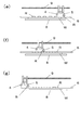
- FIG. 1 is a diagram illustrating an apparatus configuration of a printing apparatus according to an embodiment of the present invention. It is the figure which looked at the basic composition of the printing apparatus concerning the embodiment of the present invention from the top. It is a block diagram showing the control structure of the printing apparatus which concerns on embodiment of this invention. It is the figure which looked at the state after supplying the printing material to the printing apparatus which concerns on embodiment of this invention from the top. (A) It is sectional drawing of the printing apparatus which concerns on embodiment of this invention, and is a figure which shows the state after supplying a printing material, (b) It is a figure which shows a defoaming preparation stage in the sectional drawing.
- (D) It is a figure which shows the state after completion
- E In the differential pressure filling using a stencil, it is a figure which shows the state which started the backward printing after raising the pressure.
- F It is the figure which shows the state in the backward printing in the same differential pressure filling. It is a figure which shows the state after completion
- A It is sectional drawing of the vacuum printing apparatus using a stencil, It is an enlarged view which shows the state after supplying printing material.
- B In the same sectional drawing, the state where the void in printing material decreased by defoaming is shown. It is an enlarged view shown.
- FIG. 1 shows a printing apparatus 1 according to the present invention.
- a printing apparatus 1 shown in FIG. 1 prints a printing material R on a substrate W that is a substrate.
- the substrate W a wiring substrate on which a semiconductor chip is mounted, a wiring substrate having a through hole and / or a non-through hole (mainly a multilayer wiring substrate), or the like is used.
- the printing material R a liquid resin such as an epoxy resin or a silicone resin mixed with a feeler, a conductive paste in which metal fine particles are dispersed using an epoxy resin or the like as a binder, a solder paste, or the like is used.
- the printing apparatus 1 includes a vacuum chamber 2, a printing material supply means 3, a forward squeegee 4, a backward squeegee 5, a stencil 6, a stencil holder 7, a table 8, a squeegee travel shaft 9, a vacuum pump 10, a solenoid valve 11, and a control. Part 12 is provided.
- the vacuum chamber 2 forms a sealed space in which the printing material supply means 3, the outward squeegee 4, the return squeegee 5, the stencil 6, the stencil holder 7, the table 8, and the squeegee running shaft 9 can be accommodated.
- the vacuum chamber 2 is made of a structure and material that can withstand the pressure difference between the inside and outside when the inside is in a vacuum state, but has a window made of transparent resin or glass so that the inside can be visually observed. Is desirable.
- the printing material supply means 3 supplies the printing material R onto the stencil 6, and includes a storage tank that stores the printing material R, a pump that pumps the printing material R in the storage tank, and a printing material R that is pumped.
- a storage tank that stores the printing material R
- a pump that pumps the printing material R in the storage tank
- a printing material R that is pumped.
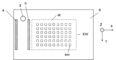
- FIG. 2 is a view of the stencil 6 viewed from above in the printing apparatus 1, but the syringe of the printing material supply means 3 discharges the printing material R while moving in the Y direction orthogonal to the squeegee running shaft 9. It has a function.
- the forward squeegee 4 and the backward squeegee 5 have a function of pushing the printing material R on the stencil 6 into the hole 6H of the stencil 6, and the forward squeegee 4 pushes the printing material R into the hole 6H.
- the process in which the squeegee 5 for forward printing and the backward path pushes the printing material R into the hole 6H is referred to as backward path printing. Both the forward printing and the backward printing are performed along the squeegee travel axis 9 (in the X direction), but the traveling direction is different by 180 degrees between the forward printing and the backward printing.
- stencil printing in which the printing material R supplied by the printing material supply means 3 at a predetermined position is pushed into the hole 6H, is referred to as forward printing.
- the print area EW is an overlapping portion of a range where the forward pass squeegee 4 and the range where the forward pass squeegee 5 prints the return pass.
- the non-printing area corresponds to an area on the stencil 6 and outside the printing area EW.
- the forward squeegee 4 and the backward squeegee 5 have a function of moving up and down, and the backward squeegee 5 is retracted to a height that does not contact the printing material R during forward printing, and the outward squeegee 4 is printed by the printing material during backward printing. It is controlled (by the control unit 12) to retreat to a height that does not contact R.
- the material of the forward squeegee 4 and the backward squeegee 5 is selected according to the characteristics of the printing material R, but the hardness is in the range of 60 to 90 degrees.
- the stencil plate 6 is made of a thin plate made of a metal material such as stainless steel and having a thickness of 0.05 mm to 2 mm, and has a hole portion 6H corresponding to a target printing pattern.
- the stencil holder 7 is made of a metal material such as stainless steel and is attached to the stencil 6 so as to form a weir having a height of about 1 cm to 2 cm, and the outer periphery of the stencil 6 is fixed on the substrate W.
- the table 8 has a mounting surface on which the substrate W is horizontally mounted, and the mounting surface is processed to have sufficient flatness. Further, if necessary, a large number of minute suction holes for sucking and holding the substrate W may be provided.
- the squeegee traveling shaft 9 regulates the moving direction of the forward squeegee 4 and the backward squeegee 5 in a certain direction, and is made of a highly rigid material. Further, the forward squeegee 4 and the backward squeegee 5 are moved along the squeegee traveling shaft 9 and moved up and down with respect to the squeegee traveling shaft 9 by a drive mechanism (not shown).
- the vacuum pump 10 is a vacuum exhaust device for depressurizing the inside of the vacuum chamber 2.
- the vacuum pump 10 is required to have a capability of quickly reaching a high vacuum state while not requiring contamination of the inside of the vacuum chamber 2 with water or oil. For this reason, a dry vacuum pump or a roots pump is suitable as the vacuum pump 10, but is not limited thereto.
- the vacuum pump 10 can be turned on / off when the vacuum chamber 2 is required to be evacuated, but there is a delay time until a steady operation is performed. For this reason, the electromagnetic valve 11 may be used when the evacuation is turned on / off. In the present embodiment, the combination of the vacuum pump 10 and the electromagnetic valve 11 is used as the vacuum evacuation means, but only the vacuum pump 10 may be used.
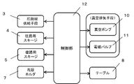
- the control unit 12 includes an input device such as a keyboard and a touch panel, hardware mainly including a memory chip and a microprocessor, a storage device incorporating a computer program for operating the hardware, and an interface for performing data communication. Composed.
- the control unit 12 is connected to the printing material supply means 3, the forward squeegee 4, the backward squeegee 5, the stencil holder 7, the table 8, the vacuum pump 10, and the electromagnetic valve 11 to perform each control.
- the basic function of the printing apparatus 1 configured as described above is that the control unit 12 controls the operation of each component so that the substrate W is filled with the printing material R in the vacuum chamber 2 by vacuum differential pressure filling. It is. In the following description, the operation is limited to the operation after the substrate W is placed on the table 7 in the vacuum chamber 2, and the operations related to the setting and resetting of the substrate W on the table 7 and the post-processing are omitted.
- the control unit 12 controls the printing material supply unit 3 to discharge the printing material R while moving it in the Y direction in FIG. 2, thereby supplying the printing material R onto the stencil 6 as shown in FIG. To do.
- the printing material R is a non-printing region, and is supplied within the movable range of at least one of the forward path squeegee 4 and the backward path squeegee 5.
- control unit 12 controls the evacuation means having the forward squeegee 4 and the backward squeegee 5 and the vacuum pump 10 and the electromagnetic valve 11 to perform the vacuum differential pressure filling as shown in FIGS. Do.
- the control unit 12 controls the forward squeegee 4 so that FIGS.
- the forward printing is performed as in d).
- the forward printing is primary printing for printing the printing material R supplied onto the stencil 6.
- the vacuum pump 10 and / or the electromagnetic valve 11 are controlled by the controller 12 so that the inside of the vacuum chamber 2 is performed at a high vacuum pressure P1.
- the control unit 12 closes the control valve 11 (in some cases, opens a leak valve not shown). ), The pressure in the vacuum chamber 2 is set to a pressure P higher than the pressure P1.
- control unit 12 controls the return squeegee 5 to perform return pass printing as shown in FIGS. 9 (e) to 9 (g).
- This return pass printing is performed under the pressure P2 different from the primary print after the forward pass printing, which is the primary print, and is therefore secondary print.
- forward printing as tertiary printing, and backward printing as quaternary printing may be performed as necessary.
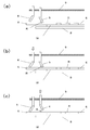
- FIG. 5 shows the vicinity of the start of forward printing in the AA cross section of FIG. 4, and FIG. 5 (a) shows a state in which the printing material R is supplied onto the stencil 6.
- the printing material R includes voids V.
- Each part of FIG. 5A is accommodated in the vacuum chamber 2, and in the state of FIG. 5A, the inside of the vacuum chamber 2 is decompressed. For this reason, in this state, the void V in the printing material R is discharged to the outside.
- the printing material R has a high viscosity, there are many voids V that are contained inside the printing material R and are not released.
- FIG. 5B shows a state in which the forward squeegee 4 is lowered by the control unit 12 and is in contact with the stencil 6. At this stage, if the return squeegee 5 is in the raised state, it is the same as the forward printing start state, but the return squeegee 5 may be in contact with the stencil 6 in the defoaming step of the present invention.
- the control unit 12 operates the forward squeegee 4 in the same direction as that during forward printing (FIG. 5C).
- a force is applied to the printing material 6 to deform it, and a part of the void V encapsulated in the printing material R moves to the vicinity of the surface of the printing material R to be sealed. It is released to the outside due to the weakened force.
- the discharged void V is a part of the void V sealed in the printing material R, the print quality is not greatly improved even if the process proceeds to the forward printing.
- control unit 12 operates the return path squeegee 5 in contact with the stencil 6 in the same direction as the return path printing to the position where the forward path printing is started.
- the forward squeegee 4 may be in contact with the stencil plate 6 but may be raised so as not to contact. Even in the operation of the return squeegee 5, force is applied to the printing material 6 and the printing material 6 is deformed, and a part of the void V encapsulated in the printing material R is released.
- the control unit 12 performs a reciprocating operation on the printing material R a plurality of times within the non-printing area by the forward squeegee 4 and the backward squeegee 5 as described above. Most of the voids V encapsulated in the material R are released. Furthermore, a shear stress is continuously applied to the printing material R by the operations of the forward squeegee 4 and the backward squeegee 5 as described above. For this reason, in the printing material R having the property of reducing the viscosity by shear stress (thixotropy), the void V in the printing material R becomes easy to move, and the release of the void V is further promoted.
- the residual voids can be greatly reduced and the printing quality can be improved as compared with the case where the printing material R is left on the stencil 6 and defoamed.
- a jig may be attached to the printing material supply means 3 to reciprocate in the Y direction, or another dedicated tool may be provided.
- a forward squeegee 4 and the backward squeegee 5 are used, it is possible to efficiently apply force to the entire printing material.
- FIG. 5 illustrates the defoaming step before the forward printing, which is the primary printing
- FIG. 6 illustrates the operation after the forward printing is performed.
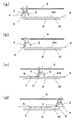
- FIG. 6 shows a close-up view of the AA cross section of FIG. 4 at the end of forward printing (start of backward printing), and
- FIG. 6 (a) shows a state where the forward printing has been completed.
- the squeegee 4 is in contact with the stencil 6 and the return squeegee 5 is raised to a height that does not contact the printing material R.
- the controller 12 After finishing the forward printing, the controller 12 increases the pressure in the vacuum chamber 2 by controlling the electromagnetic valve 12 and the like, and prepares for the backward printing. This state is shown in FIGS. 6B and 6C. First, in FIG. 6B, the controller 12 lowers the return path squeegee 5 until it contacts the stencil 6 while the forward path squeegee 4 is in contact with the stencil 6. Then, after the return squeegee 5 contacts the stencil 6, the control unit 12 controls the height so that the forward squeegee 4 is raised and separated from the stencil 6.
- the stencil plate 6 can maintain a state of being in close contact with the substrate W, which is a printing material, and the printing material R can be prevented from oozing out other than the portion facing the hole 6H on the substrate W.
- FIGS. 7A to 7C A similar operation can be performed after the return pass printing. This state is shown in FIGS. 7A to 7C.
- the control unit 12 lowers the forward pass squeegee 4 until it contacts the stencil 6 while the return pass squeegee 5 is in contact with the stencil 6. Then, after the forward squeegee 4 comes into contact with the stencil 6, the control unit 12 controls the height so that the backward squeegee 5 is raised and separated from the stencil 6. Thereafter, if further forward printing (tertiary printing) is performed, the forward squeegee 4 is kept in contact with the stencil 6, but if tertiary printing is not performed, the forward squeegee 4 is raised.
- the forward printing is referred to as primary printing and the backward printing is referred to as secondary printing.
- the “forward printing + return printing” in the state of the pressure P1 is set as the primary printing, and the “forward printing by the pressure P2”. + Return printing "(or" outgoing printing only ”) may be secondary printing, but when the squeegee used for printing is separated from the stencil, contact the squeegee not used for printing as in this embodiment. It is desirable to do this first.
Landscapes
- Engineering & Computer Science (AREA)
- Manufacturing & Machinery (AREA)
- Microelectronics & Electronic Packaging (AREA)
- Mechanical Engineering (AREA)
- Screen Printers (AREA)
- Printing Methods (AREA)
Abstract
減圧下で孔版印刷するのに際して、高粘度の印刷材であってもボイドを抑制し、品質に優れた印刷が可能な印刷装置および印刷方法を提供すること。具体的には、孔版上の非印刷領域に印刷材を供給する印刷材供給手段と、往路印刷を行う往路用スキージと、復路印刷を行う復路用スキージと、前記印刷材供給手段、前記往路用スキージおよび前記復路用スキージを収納する真空チャンバーと、前記真空チャンバー内を減圧する真空排気手段と、前記印刷材供給手段と前記往路用スキージと前記復路用スキージと真空排気手段を制御する制御部とを備え、前記制御部が、前記往路用スキージと前記復路用スキージを、孔版上の非印刷領域内で往路方向と復路方向に往復動作を行なうように制御する印刷装置および印刷方法を提供する。
Description
本発明は、孔版印刷により電子部品の樹脂封止や回路基板への樹脂充填を行う、印刷装置および印刷方法に関するものである。
回路基板上の電子部品を樹脂封止したり回路基板の孔内に導電性ペースト等を充填するために、絶縁性樹脂ペーストや導電性ペースト等を印刷材とした孔版印刷が行われている。孔版印刷は、印刷材を孔版上に供給した後に、孔版上のスキージを動かすことにより、孔版の孔内に印刷材を押し込むものであるが、印刷材を押し込む際に空気を巻き込んで印刷材中にボイドが残存することがある。
回路基板上の電子部品を樹脂封止したり回路基板への樹脂充填においては、電子機器の信頼性の観点から、封止樹脂および充填樹脂にボイドが存在することは好ましくない。そのため、孔版印刷を真空雰囲気下で行う真空印刷装置の普及が進んでいる。特に、真空雰囲気下での複数回の孔版印刷の間で真空度を下げる(大気圧に近づける)、真空差圧充填法を用いることにより、ボイドが少なく表面の平坦性に優れた樹脂封止および樹脂充填が可能になっている(特許文献1)。
真空差圧充填の一例を図8および図9を用いて説明する。図8および図9は、基板Wに印刷材Rを印刷する例を示しており、孔版6の孔部6Hに往路用スキージ4および復路用スキージ5を用いて印刷材Rを充填する。
図8(a)は孔版6上に印刷材Rを供給した印刷開始前の状態、図8(b)~図8(d)は一次印刷の状態を示す図であり、この一次印刷は圧力P1の真空下で行われる。まず、孔版6上に供給された印刷材Rを往路用スキージ4が孔部側に移動させ(図8(b))、孔部6Hに印刷材Rを押し込んで行き(図8(c))、全ての孔部6Hに印刷材Rを充填する(図8(d))。しかし、孔部6Hへの印刷材Rの充填が不充分で、ボイドVが生じることがある。ここで、一次印刷は圧力P1の真空下で行われているため、周囲を圧力P1よりも高い圧力Pにすることで、P1とPの比に応じた分だけボイドが縮小するとともに、流動により印刷材Rからボイドが放出されることもある。これにより、孔部に一次印刷で充填された印刷材Rの見かけ体積が縮小し、その分だけ孔部内の印刷材Rの表面が凹む(図9(e))。
次に、孔部内の印刷材Rの平坦性を改善するために二次印刷を行う(図9)。この二次印刷を行う時の圧力P2は、P1に比べて10倍以上の高い圧力である必要があるが、大気圧以下の減圧下で実施される。図9において、二次印刷は復路用スキージ5を用いて実施され(図9(f))、二次印刷の後(図9(g))は、ボイドが少なく、表面の平坦性に優れた樹脂封止が形成される。
なお、図8(a)のように、孔版6(の非印刷領域)上に印刷材Rを供給した状態において、図10(a)に示すように印刷材R中にボイドVが含まれるていることがある。このようなボイドVは、印刷材Rそのものに含まれていることもあるが、印刷材供給手段3から供給する際に、供給ライン内で混入するものもあり、孔版6上に供給する前段階で排除するのが難しい。このため、一次印刷を開始する前にボイドVを除去するために、孔版6上に供給された後に減圧下で一定時間放置して脱泡(図10(b))する工程を設けることがある。
孔版印刷を真空雰囲気下で行なう真空印刷に対して、昨今、高粘度の印刷材Rへの適用も要望されている。しかし、印刷材Rが高粘度化することで以下のような課題が生じている。
まず、図10(a)のように孔版6上に放置された状態で周囲が減圧であっても、高粘度であるため図10(b)のように内部にボイドが封じ込められ、印刷材Rの中に多くのボイドが残存する状態で孔版印刷を開始せざるを得なくなる。差圧充填を行なってもボイド自体を一次印刷時より小さくすることは出来るが数を減らすことは困難なので、二次印刷完了後も多数のボイドが残存してしまう。
また、高粘度の印刷材Rは一般的に粘着性も高いものが多く、この高粘着性に伴う弊害もある。例えば、一次印刷から二次印刷に切り替える際に(図11(a))、まず往路用スキージ4を上昇させるが、この際に印刷材Rを介した粘着により孔版6が持ち上がるという現象も現れる(図11(b))。このように孔版6が持ち上がると、孔版6の孔部6H周囲に印刷材Rが染み出すように広がることもあり、印刷品質の低下を招く。
本発明は上記問題に鑑みて成されたものであり、減圧下で孔版印刷するのに際して、高粘度の印刷材であってもボイドを抑制し、品質に優れた印刷が可能な印刷装置および印刷方法を提供するものである。
上記の課題を解決するために、請求項1に記載の発明は、
減圧下で、孔版を用いて、被印刷物に対して印刷材を印刷する印刷装置であって、
孔版上の非印刷領域に印刷材を供給する印刷材供給手段と、往路印刷を行う往路用スキージと、復路印刷を行う復路用スキージと、前記印刷材供給手段、前記往路用スキージおよび前記復路用スキージを収納する真空チャンバーと、前記真空チャンバー内を減圧する真空排気手段と、前記印刷材供給手段と前記往路用スキージと前記復路用スキージと真空排気手段を制御する制御部とを備え、
前記制御部が、前記往路用スキージと前記復路用スキージを、孔版上の非印刷領域内で印刷材に対して、往路方向と復路方向に往復動作を行なうように制御する機能を有した印刷装置である。
減圧下で、孔版を用いて、被印刷物に対して印刷材を印刷する印刷装置であって、
孔版上の非印刷領域に印刷材を供給する印刷材供給手段と、往路印刷を行う往路用スキージと、復路印刷を行う復路用スキージと、前記印刷材供給手段、前記往路用スキージおよび前記復路用スキージを収納する真空チャンバーと、前記真空チャンバー内を減圧する真空排気手段と、前記印刷材供給手段と前記往路用スキージと前記復路用スキージと真空排気手段を制御する制御部とを備え、
前記制御部が、前記往路用スキージと前記復路用スキージを、孔版上の非印刷領域内で印刷材に対して、往路方向と復路方向に往復動作を行なうように制御する機能を有した印刷装置である。
請求項2に記載の発明は、請求項1に記載の印刷装置であって、
前記印刷材にせん断応力を加えるように、前記制御部が、前記往路用スキージと前記復路用スキージの前記往復運動を制御する印刷装置である。
前記印刷材にせん断応力を加えるように、前記制御部が、前記往路用スキージと前記復路用スキージの前記往復運動を制御する印刷装置である。
請求項3に記載の発明は、請求項1または請求項2に記載の印刷装置であって、
前記往路用スキージと前記復路用スキージが前記往復動作を行う際に、
前記制御部が、部前記往路用スキージと前記復路用スキージの少なくとも一方が前記孔版に接触するように制御する印刷装置である。
前記往路用スキージと前記復路用スキージが前記往復動作を行う際に、
前記制御部が、部前記往路用スキージと前記復路用スキージの少なくとも一方が前記孔版に接触するように制御する印刷装置である。
請求項4に記載の発明は、請求項1から請求項3の何れかに記載の印刷装置であって、
前記孔版上の印刷領域を往路用スキージまたは復路用スキージの一方のスキージにより、前記印刷材を印刷した後、他方のスキージを前記孔版に接触させてから、前記一方のスキージが前記孔版から離すように、前記スキージ制御部が、前記往路用スキージと前記復路用スキージの高さ制御を行なう印刷装置である。
前記孔版上の印刷領域を往路用スキージまたは復路用スキージの一方のスキージにより、前記印刷材を印刷した後、他方のスキージを前記孔版に接触させてから、前記一方のスキージが前記孔版から離すように、前記スキージ制御部が、前記往路用スキージと前記復路用スキージの高さ制御を行なう印刷装置である。
請求項5に記載の発明は、
孔版を用いて、被印刷物に対して印刷材を印刷する印刷方法であって、
前期孔版上の非印刷領域内に前記印刷材を供給する印刷材供給工程と、真空雰囲気下で、前記非印刷領域内の前記印刷材にせん断応力を加える脱泡工程と、往路用スキージを用いて往路印刷を行う往路印刷工程と、復路用スキージを用いて復路印刷を行う復路印刷工程と、からなる印刷方法である。
孔版を用いて、被印刷物に対して印刷材を印刷する印刷方法であって、
前期孔版上の非印刷領域内に前記印刷材を供給する印刷材供給工程と、真空雰囲気下で、前記非印刷領域内の前記印刷材にせん断応力を加える脱泡工程と、往路用スキージを用いて往路印刷を行う往路印刷工程と、復路用スキージを用いて復路印刷を行う復路印刷工程と、からなる印刷方法である。
請求項6に記載の発明は、請求項5に記載の印刷方法であって、
前記往路印刷工程の後は、前記復路用スキージを前記孔版に接触させてから、前記往路用スキージを前記孔版から離すことを特徴とする印刷方法である。
前記往路印刷工程の後は、前記復路用スキージを前記孔版に接触させてから、前記往路用スキージを前記孔版から離すことを特徴とする印刷方法である。
請求項7に記載の発明は、請求項6に記載の印刷方法であって、
前記復路印刷工程の後は、前記往路用スキージを前記孔版に接触させてから、前記復路用スキージを前記孔版から離すことを特徴とする印刷方法である。
前記復路印刷工程の後は、前記往路用スキージを前記孔版に接触させてから、前記復路用スキージを前記孔版から離すことを特徴とする印刷方法である。
本発明により、減圧下で孔版印刷するのに際して、高粘度の印刷材であってもボイドを抑制し、品質に優れた印刷が可能となる。
本発明の実施形態につき、図面を用いて説明する。
図1は、本発明に係る印刷装置1である。図1に示す印刷装置1は被印刷物である基板Wに印刷材Rを印刷するものである。ここで、基板Wとして、半導体チップを搭載した配線基板や、貫通孔または/および非貫通孔を有する配線基板(主に多層配線基板)等が用いられる。また、印刷材Rとしては、フィーラーを混入したエポキシ樹脂やシリコーン樹脂等の液状樹脂、エポキシ樹脂等をバインダーとして金属微粒子を分散させた導電性ペースト、ハンダペースト等が用いられる。
図1は、本発明に係る印刷装置1である。図1に示す印刷装置1は被印刷物である基板Wに印刷材Rを印刷するものである。ここで、基板Wとして、半導体チップを搭載した配線基板や、貫通孔または/および非貫通孔を有する配線基板(主に多層配線基板)等が用いられる。また、印刷材Rとしては、フィーラーを混入したエポキシ樹脂やシリコーン樹脂等の液状樹脂、エポキシ樹脂等をバインダーとして金属微粒子を分散させた導電性ペースト、ハンダペースト等が用いられる。
印刷装置1は、真空チャンバー2、印刷材供給手段3、往路用スキージ4、復路用スキージ5、孔版6、孔版ホルダ7、テーブル8、スキージ走行軸9、真空ポンプ10、電磁弁11、および制御部12を備えている。
真空チャンバー2は、印刷材供給手段3、往路用スキージ4、復路用スキージ5、孔版6、孔版ホルダ7、テーブル8、およびスキージ走行軸9を収納可能な密閉空間を形成するものである。真空チャンバー2は、内部を真空状態にした時の、内外の圧力差に耐える構造、材料によって構成されるが、内部を目視観察できるような透明な樹脂やガラスから成る窓部を備えていることが望ましい。
印刷材供給手段3は、孔版6上に印刷材Rを供給するものであり、印刷材Rを貯留した貯留タンク、貯留タンク内の印刷材Rを圧送する圧送ポンプ及び圧送された印刷材Rを吐出するシリンジを備えているが、図1ではシリンジ部分のみを図示している。また、図2は印刷装置1内の、上から孔版6を見た図であるが印刷材供給手段3のシリンジは、スキージ走行軸9に直交するY方向に移動しながら印刷材Rを吐出する機能を有している。
往路用スキージ4および復路用スキージ5は、孔版6上の印刷材Rを孔版6の孔部6Hに押し込む機能を有しており、往路用スキージ4が印刷材Rを孔部6Hに押し込む工程を往路印刷、復路用スキージ5が印刷材Rを孔部6Hに押し込む工程を復路印刷とする。往路印刷と復路印刷はともにスキージ走行軸9に沿って(X方向に)行なわれるが、往路印刷と復路印刷では進行方向が180度異なる。なお、本明細書においては、印刷材供給手段3が所定位置で供給した状態の印刷材Rを孔部6Hに押し込む孔版印刷を往路印刷としている。図2において、印刷領域EWは、往路用スキージ4により往路印刷する範囲と復路用スキージ5により復路印刷する範囲の重複部分である。また、非印刷領域とは、孔版6上であって印刷領域EWの外側の領域に相当する。
往路用スキージ4および復路用スキージ5は上下移動する機能を有しており、往路印刷時には復路用スキージ5が印刷材Rに接触しない高さに退避し、復路印刷時には往路用スキージ4が印刷材Rに接触しない高さに退避するよう(制御部12により)制御される。
往路用スキージ4および復路用スキージ5は上下移動する機能を有しており、往路印刷時には復路用スキージ5が印刷材Rに接触しない高さに退避し、復路印刷時には往路用スキージ4が印刷材Rに接触しない高さに退避するよう(制御部12により)制御される。
往路用スキージ4および復路用スキージ5の材質は、印刷材Rの特性に応じて選ばれるが、硬度としては60~90度の範囲になる。
孔版6は、ステンレス鋼等の金属材質の厚さ0.05mm~2mmの薄板からなり、目的とする印刷パターンに応じた孔部6Hを備える。
孔版ホルダ7はステンレス鋼等の金属材質で、高さ1cm~2cm程度の堰を形成するように孔版6に取り付けられ、基板W上に孔版6外周部を固定している。
テーブル8は、基板Wを水平に搭載する載置面を有しており、載置面は充分な平面度を有するように加工されている。また、必要に応じて基板Wを吸着保持するための微小な吸着孔を多数備えていてもよい。
スキージ走行軸9は、往路用スキージ4および復路用スキージ5の移動方向を一定方向に規制するものであり、剛性の高い材質によって構成されている。また、往路用スキージ4および復路用スキージ5は、図示しない駆動機構により、スキージ走行軸9に沿って移動するとともに、スキージ走行軸9に対して上下移動も行なう。
真空ポンプ10は、真空チャンバー2内を減圧するための真空排気装置である。ここで、真空チャンバー2内を水や油で汚染しないことを必須条件としつつ、素早く高真空状態に到達させる性能が真空ポンプ10には求められる。このため、真空ポンプ10として、ドライ真空ポンプやルーツポンプが適しているが、これに限定されるものではない。
また、真空チャンバー2内の真空排気要否に際して、真空ポンプ10をオンオフすることも可能であるが、定常動作になるまでの遅れ時間等がある。このため、真空排気のオンオフを行なうに際して電磁弁11を用いてもよい。なお、本実施形態においては真空ポンプ10と電磁弁11の組み合わを真空排気手段としているが、真空ポンプ10のみであってもよい。
制御部12は、キーボードやタッチパネル等の入力装置、メモリチップやマイクロプロセッサなどを主体としたハードウェア、このハードウェアを動作させるためのコンピュータプログラムを組み込んだ記憶装置、及びデータ通信を行なうインターフェースなどから構成される。制御部12は、印刷材供給手段3、往路用スキージ4、復路用スキージ5、孔版ホルダ7、テーブル8、真空ポンプ10、電磁バルブ11に接続して、各々の制御を行なう。
以上のような構成の印刷装置1の基本的な機能は、真空チャンバー2内において、基板Wに印刷材Rを真空差圧充填を行なうよう、制御部12が各構成要素の動作を制御するものである。なお、以下の説明においては、真空チャンバー2内のテーブル7上に基板Wを配置後の動作に限定し、テーブル7上への基板Wのセット、リセット等の準備、後処理に関する動作は省く。
まず、制御部12は、まず印刷材供給手段3を制御して、図2のY方向に移動させながら印刷材Rを吐出することで、図4のように孔版6上に印刷材Rを供給する。ここで、印刷材Rは非印刷領域であって、往路用スキージ4または復路用スキージ5の少なくとも一方の可動範囲内に供給される。
この後、制御部12は往路用スキージ4および復路用スキージ5および、真空ポンプ10および電磁バルブ11とを有する真空排気手段を制御して、図8および図9に示すような真空差圧充填を行なう。
すなわち、印刷材供給手段3で図8(a)のように孔版6上に印刷材Rを供給した後に、制御部12は往路用スキージ4を制御して、図8(b)~図8(d)のように往路印刷を行なう。ここで、この往路印刷は、孔版6上に供給された印刷材Rを印刷する一次印刷となる。また、この往路印刷(一次印刷)において、真空チャンバー2内は高真空状態の圧力P1で行われるよう真空ポンプ10および/または電磁バルブ11は制御部12により制御される。
図8(d)に示すように往路用スキージ4による往路印刷(一次印刷)の後に、制御部12は制御バルブ11を閉じることで(場合によっては図示していないリークバルブの開動作も行なって)、真空チャンバー2内の圧力を圧力P1よりも高い圧力Pにする。
その後に、制御部12は復路用スキージ5を制御して、図9(e)~図9(g)のように復路印刷を行なう。この復路印刷は、一次印刷である往路印刷の後に、一次印刷とは異なる圧力P2下で行なうので二次印刷となる。この後に、真空チャンバー2内の圧力を制御しつつ、三次印刷としての往路印刷、更に四次印刷としての復路印刷等を必要に応じて行なってもよい。
以上が、印刷装置1による差圧充填の基本動作についての説明であるが、以後は本発明の主な実施形態に関する説明を図5、図6および図7を用いて行なう。
図5は、図4のA-A断面の、往路印刷開始近傍を示したものであり、図5(a)は印刷材Rが孔版6上に供給された状態を示したものである。ここで、印刷材RはボイドVを含んでいる。図5(a)の各部は真空チャンバー2内に収納されているものであり、図5(a)の状態において真空チャンバー2内は減圧されている。このため、この状態において印刷材R内のボイドVは外部に放出されていく。ただし、印刷材Rが高粘度であると印刷材Rの内側に封じ込められて放出されないボイドVが多く存在する。
図5(b)は、制御部12により往路用スキージ4を低下させて孔版6に接触した状態である。この段階で、復路用スキージ5が上昇状態であれば往路印刷開始状態と同じであるが、本発明における脱泡工程においては復路用スキージ5が孔版6に接触していてもよい。
次に、制御部12は、往路用スキージ4を往路印刷時と同じ方向に動作させる(図5(c))。このように往路用スキージ4を動作させることで印刷材6に力が加わり変形し、印刷材R内に封じ込められていたボイドVの一部が、印刷材Rの表面近傍に移動し、封じこめられる力が弱くなったことにより外部に放出される。ただし、放出されるボイドVは印刷材Rに封じこめられたボイドVの一部であるので、このまま往路印刷に移行しても印刷品質は大きく改善されない。
そこで、図5(c)に示したような印刷材Rを変形移動させるための往路用スキージ4の移動は非印刷領域内に止めて一旦停止させる。
その後に、制御部12は復路用スキージ5を孔版6に接触させた状態で、復路印刷と同じ方向に、往路印刷を開始した位置まで動作させる。この動作に際して、往路用スキージ4は孔版6に接触していてもよいが接触しないように上昇させていてもよい。この復路用スキージ5の動作でも、印刷材6には力が加わり変形し、印刷材R内に封じ込められていたボイドVの一部が放出される。
本発明における脱泡工程は、制御部12により、以上のような往路用スキージ4と復路用スキージ5による非印刷領域内で印刷材Rに対しての往復動作を複数回行なうものであり、印刷材Rに封じ込められていたボイドVの多くが放出される。さらに、上記のような往路用スキージ4と復路用スキージ5の動作により印刷材Rにせん断応力が連続的に加わる。このため、せん断応力により粘度が低下する性質(チキソトロイピー)を有する印刷材Rにおいては、印刷材R内でのボイドVが移動しやすくなって、ボイドVの放出が一層促進される。
以上のように、本発明では、印刷材Rが高粘度の場合において、孔版6上に放置して脱泡した場合に比べ、残留ボイドを大幅に低減して、印刷品質の向上が図れる。
なお、孔版6上に供給された印刷材Rに力を加えて変形させる手段として、印刷材供給手段3に治具を付けてY方向に往復運動させたり、別の専用時具を設けることも考えられるが、往路用スキージ4と復路用スキージ5を用いれば、印刷材全体に効率的に力を加えることが出来る。
図5では、一次印刷である往路印刷を行なう前の脱泡工程について説明したが、図6は往路印刷実施後の動作について説明するものである。図6は、図4のA-A断面の、往路印刷終了(復路印刷開始)段階の近傍図を示したものであり、図6(a)は往路印刷が終了した状態を示していおり、往路用スキージ4は孔版6に接触し、復路用スキージ5は印刷材Rに接触しない高さに上昇している。
往路印刷終了後、制御部12は電磁バルブ12等の制御により真空チャンバー2内の圧力を上げるとともに、復路印刷の準備を行なう。その状態を示したのが、図6(b)および図6(c)である。まず、図6(b)において、制御部12は、往路用スキージ4が孔版6に接触した状態のまま復路用スキージ5を孔版6に接触するまで下降させる。そうして、復路用スキージ5が孔版6に接触してから、制御部12は往路用スキージ4を上昇させて孔版6から離すように高さ制御をする。このようにすることで、往路用スキージ4と孔版6と接触している印刷材Rが粘着性を有していても、往路用スキージ4近くで孔版6を復路用スキージ5が押さえているので、孔版6が往路用スキージ4の上昇に伴って持ち上がるようなことはない。
このため、孔版6は被印刷材である基板Wと密着した状態を維持できて、基板W上の孔部6Hに相対する部分以外に印刷材Rが染み出すことが防げる。
同様な動作は復路印刷の後に実施することも可能である。その状態を示したのが、図7(a)ないし図7(c)である。まず、図7(a)に示すように復路印刷終了後、制御部12は復路用スキージ5が孔版6に接触した状態のまま往路用スキージ4を孔版6に接触するまで下降させる。そうして、往路用スキージ4が孔版6に接触してから、制御部12は復路用スキージ5を上昇させて孔版6から離すように高さ制御をする。この後さらに往路印刷(三次印刷)を行なうのであれば往路用スキージ4を孔版6に接触させたままにしておくが、三次印刷を行なわないのであれば、往路用スキージ4を上昇させる。この際、往路用スキージ4には若干の印刷材Rが付着していることもあるが、復路用スキージ5と孔版6の間に存在する印刷材Rに比べて量的に少ないので、復路用スキージ5を上昇させた後に往路用スキージ4を上昇させても孔版6の持ち上がりはほとんどない。
このように、往路印刷後および復路印刷後の、往路用スキージ4および復路用スキージ5の動作を制御することにより、所望個所以外への印刷材の染み出しのない高品質の印刷を行なうことが出来る。
ところで、本実施形態において、往路印刷を一次印刷、復路印刷を二次印刷というよにしていたが、圧力P1の状態での「往路印刷+復路印刷」を一次印刷として、圧力P2による「往路印刷+復路印刷」(または「往路印刷」のみ)を二次印刷としてもよいが、印刷に用いたスキージを孔版から離す際は、本実施形態と同様に印刷に用いなかったスキージの孔版への接触を先に行なうことが望ましい。
1 印刷装置
2 真空チャンバー
3 印刷材供給手段
4 往路用スキージ
5 復路用スキージ
6 孔版
6H 孔部
7 孔版ホルダ
8 テーブル
9 スキージ走行軸
10 真空ポンプ
11 電磁弁
12 制御部
EW 印刷領域
R 印刷材
W 基板(被印刷物)
2 真空チャンバー
3 印刷材供給手段
4 往路用スキージ
5 復路用スキージ
6 孔版
6H 孔部
7 孔版ホルダ
8 テーブル
9 スキージ走行軸
10 真空ポンプ
11 電磁弁
12 制御部
EW 印刷領域
R 印刷材
W 基板(被印刷物)
Claims (7)
- 減圧下で、孔版を用いて、被印刷物に対して印刷材を印刷する印刷装置であって、
孔版上の非印刷領域に印刷材を供給する印刷材供給手段と、
往路印刷を行う往路用スキージと、
復路印刷を行う復路用スキージと、
前記印刷材供給手段、前記往路用スキージおよび前記復路用スキージを収納する真空チャンバーと、
前記真空チャンバー内を減圧する真空排気手段と、
前記印刷材供給手段と前記往路用スキージと前記復路用スキージと真空排気手段を制御する制御部とを備え、
前記制御部が、前記往路用スキージと前記復路用スキージを、孔版上の非印刷領域内で印刷材に対して、往路方向と復路方向に往復動作を行なうように制御する機能を有した印刷装置。 - 請求項1に記載の印刷装置であって、
前記印刷材にせん断応力を加えるように、前記制御部が、前記往路用スキージと前記復路用スキージの前記往復運動を制御する印刷装置。 - 請求項1または請求項2に記載の印刷装置であって、
前記往路用スキージと前記復路用スキージが前記往復動作を行う際に、
前記制御部が、部前記往路用スキージと前記復路用スキージの少なくとも一方が前記孔版に接触するように制御する印刷装置。 - 請求項1から請求項3の何れかに記載の印刷装置であって、
前記孔版上の印刷領域を往路用スキージまたは復路用スキージの一方のスキージにより、前記印刷材を印刷した後、
他方のスキージを前記孔版に接触させてから、前記一方のスキージが前記孔版から離すように、前記スキージ制御部が、前記往路用スキージと前記復路用スキージの高さ制御を行なう印刷装置。 - 孔版を用いて、被印刷物に対して印刷材を印刷する印刷方法であって、
前期孔版上の非印刷領域内に前記印刷材を供給する印刷材供給工程と、
真空雰囲気下で、前記非印刷領域内の前記印刷材にせん断応力を加える脱泡工程と、
往路用スキージを用いて往路印刷を行う往路印刷工程と、
復路用スキージを用いて復路印刷を行う復路印刷工程と、からなる印刷方法。 - 請求項5に記載の印刷方法であって、
前記往路印刷工程の後は、
前記復路用スキージを前記孔版に接触させてから、前記往路用スキージを前記孔版から離すことを特徴とする印刷方法。 - 請求項6に記載の印刷方法であって、
前記復路印刷工程の後は、
前記往路用スキージを前記孔版に接触させてから、前記復路用スキージを前記孔版から離すことを特徴とする印刷方法。
Applications Claiming Priority (2)
| Application Number | Priority Date | Filing Date | Title |
|---|---|---|---|
| JP2017028793A JP2018134746A (ja) | 2017-02-20 | 2017-02-20 | 印刷装置および印刷方法 |
| JP2017-028793 | 2017-12-25 |
Publications (1)
| Publication Number | Publication Date |
|---|---|
| WO2018151252A1 true WO2018151252A1 (ja) | 2018-08-23 |
Family
ID=63169379
Family Applications (1)
| Application Number | Title | Priority Date | Filing Date |
|---|---|---|---|
| PCT/JP2018/005485 Ceased WO2018151252A1 (ja) | 2017-02-20 | 2018-02-16 | 印刷装置および印刷方法 |
Country Status (2)
| Country | Link |
|---|---|
| JP (1) | JP2018134746A (ja) |
| WO (1) | WO2018151252A1 (ja) |
Cited By (2)
| Publication number | Priority date | Publication date | Assignee | Title |
|---|---|---|---|---|
| CN109605914A (zh) * | 2018-12-21 | 2019-04-12 | 北京铂阳顶荣光伏科技有限公司 | 一种丝网印刷装置及丝网印刷设备 |
| CN111730960A (zh) * | 2020-07-08 | 2020-10-02 | 深圳市斯迈得半导体有限公司 | 一种用于Mini背光真空印刷装置及其使用方法 |
Citations (6)
| Publication number | Priority date | Publication date | Assignee | Title |
|---|---|---|---|---|
| JPH09314799A (ja) * | 1996-05-30 | 1997-12-09 | Matsushita Electric Ind Co Ltd | スクリーン印刷方法およびスクリーン印刷装置 |
| JP2000309081A (ja) * | 1999-04-27 | 2000-11-07 | Matsushita Electric Ind Co Ltd | スクリーン印刷方法 |
| JP2003300302A (ja) * | 2002-04-09 | 2003-10-21 | Newlong Seimitsu Kogyo Co Ltd | スクリーン印刷方法 |
| JP2011253871A (ja) * | 2010-06-01 | 2011-12-15 | Panasonic Corp | 半導体装置の製造方法 |
| US20150283637A1 (en) * | 2014-04-04 | 2015-10-08 | Robert Gray | Device and method for printing a thixotropic medium onto a pcb |
| JP2016155227A (ja) * | 2015-02-23 | 2016-09-01 | 東レエンジニアリング株式会社 | 印刷装置および印刷方法 |
Family Cites Families (3)
| Publication number | Priority date | Publication date | Assignee | Title |
|---|---|---|---|---|
| JP3145959B2 (ja) * | 1997-07-18 | 2001-03-12 | 東レエンジニアリング株式会社 | 電子部品の樹脂封止方法 |
| JP2003324115A (ja) * | 2002-05-01 | 2003-11-14 | Canon Inc | 封止樹脂の印刷方法 |
| JP4625287B2 (ja) * | 2004-08-18 | 2011-02-02 | Smk株式会社 | 電子部品用封止樹脂組成物 |
-
2017
- 2017-02-20 JP JP2017028793A patent/JP2018134746A/ja active Pending
-
2018
- 2018-02-16 WO PCT/JP2018/005485 patent/WO2018151252A1/ja not_active Ceased
Patent Citations (6)
| Publication number | Priority date | Publication date | Assignee | Title |
|---|---|---|---|---|
| JPH09314799A (ja) * | 1996-05-30 | 1997-12-09 | Matsushita Electric Ind Co Ltd | スクリーン印刷方法およびスクリーン印刷装置 |
| JP2000309081A (ja) * | 1999-04-27 | 2000-11-07 | Matsushita Electric Ind Co Ltd | スクリーン印刷方法 |
| JP2003300302A (ja) * | 2002-04-09 | 2003-10-21 | Newlong Seimitsu Kogyo Co Ltd | スクリーン印刷方法 |
| JP2011253871A (ja) * | 2010-06-01 | 2011-12-15 | Panasonic Corp | 半導体装置の製造方法 |
| US20150283637A1 (en) * | 2014-04-04 | 2015-10-08 | Robert Gray | Device and method for printing a thixotropic medium onto a pcb |
| JP2016155227A (ja) * | 2015-02-23 | 2016-09-01 | 東レエンジニアリング株式会社 | 印刷装置および印刷方法 |
Cited By (2)
| Publication number | Priority date | Publication date | Assignee | Title |
|---|---|---|---|---|
| CN109605914A (zh) * | 2018-12-21 | 2019-04-12 | 北京铂阳顶荣光伏科技有限公司 | 一种丝网印刷装置及丝网印刷设备 |
| CN111730960A (zh) * | 2020-07-08 | 2020-10-02 | 深圳市斯迈得半导体有限公司 | 一种用于Mini背光真空印刷装置及其使用方法 |
Also Published As
| Publication number | Publication date |
|---|---|
| JP2018134746A (ja) | 2018-08-30 |
Similar Documents
| Publication | Publication Date | Title |
|---|---|---|
| US6823784B2 (en) | Screen printing method including degassing bubbles in the coating material | |
| EP2669738A1 (en) | Method and apparatus for forming pattern | |
| US20090183849A1 (en) | Full-field solder coverage | |
| KR20140028075A (ko) | 솔더 페이스트 | |
| WO2018151252A1 (ja) | 印刷装置および印刷方法 | |
| JP6438797B2 (ja) | 印刷装置および印刷方法 | |
| JP2016154193A (ja) | 基板処理装置、基板処理システム、及び基板処理方法 | |
| JP6461662B2 (ja) | 印刷装置および印刷方法 | |
| EP4364949A1 (en) | Referencing system for singulated workpieces | |
| WO2003037631A1 (en) | Screen printing apparatus | |
| JP2011035091A (ja) | ビア充填方法及び装置 | |
| JP2016185597A (ja) | 印刷装置および印刷方法 | |
| JP5013318B2 (ja) | 電子部品の実装装置及び実装方法 | |
| JP6343892B2 (ja) | スキージ及び印刷方法 | |
| JP4408299B2 (ja) | 印刷装置 | |
| JP4682924B2 (ja) | スクリーン印刷方法 | |
| JP5464087B2 (ja) | 導電材料充填装置 | |
| JP2000216526A (ja) | 真空孔版印刷方法 | |
| JP6127576B2 (ja) | 真空印刷装置 | |
| JP4150372B2 (ja) | スクリーン印刷装置 | |
| JP2010287702A (ja) | 電子部品実装機およびその融剤転写装置 | |
| JP2005199545A (ja) | スクリーン印刷装置およびスクリーン印刷方法 | |
| JP3223298B2 (ja) | 電子部品の製造法 | |
| US9808915B2 (en) | Selective vacuum printing machine | |
| JP2001267339A (ja) | 電子部品の製造装置及び製造方法 |
Legal Events
| Date | Code | Title | Description |
|---|---|---|---|
| 121 | Ep: the epo has been informed by wipo that ep was designated in this application |
Ref document number: 18753810 Country of ref document: EP Kind code of ref document: A1 |
|
| NENP | Non-entry into the national phase |
Ref country code: DE |
|
| 122 | Ep: pct application non-entry in european phase |
Ref document number: 18753810 Country of ref document: EP Kind code of ref document: A1 |