WO2018142913A1 - 電気接続アセンブリ及びその製造方法 - Google Patents
電気接続アセンブリ及びその製造方法 Download PDFInfo
- Publication number
- WO2018142913A1 WO2018142913A1 PCT/JP2018/000932 JP2018000932W WO2018142913A1 WO 2018142913 A1 WO2018142913 A1 WO 2018142913A1 JP 2018000932 W JP2018000932 W JP 2018000932W WO 2018142913 A1 WO2018142913 A1 WO 2018142913A1
- Authority
- WO
- WIPO (PCT)
- Prior art keywords
- terminal
- electric wire
- connection
- wire
- protruding portion
- Prior art date
- Legal status (The legal status is an assumption and is not a legal conclusion. Google has not performed a legal analysis and makes no representation as to the accuracy of the status listed.)
- Ceased
Links
Images










Classifications
-
- H—ELECTRICITY
- H01—ELECTRIC ELEMENTS
- H01R—ELECTRICALLY-CONDUCTIVE CONNECTIONS; STRUCTURAL ASSOCIATIONS OF A PLURALITY OF MUTUALLY-INSULATED ELECTRICAL CONNECTING ELEMENTS; COUPLING DEVICES; CURRENT COLLECTORS
- H01R4/00—Electrically-conductive connections between two or more conductive members in direct contact, i.e. touching one another; Means for effecting or maintaining such contact; Electrically-conductive connections having two or more spaced connecting locations for conductors and using contact members penetrating insulation
- H01R4/02—Soldered or welded connections
- H01R4/023—Soldered or welded connections between cables or wires and terminals
- H01R4/024—Soldered or welded connections between cables or wires and terminals comprising preapplied solder
-
- H—ELECTRICITY
- H01—ELECTRIC ELEMENTS
- H01R—ELECTRICALLY-CONDUCTIVE CONNECTIONS; STRUCTURAL ASSOCIATIONS OF A PLURALITY OF MUTUALLY-INSULATED ELECTRICAL CONNECTING ELEMENTS; COUPLING DEVICES; CURRENT COLLECTORS
- H01R4/00—Electrically-conductive connections between two or more conductive members in direct contact, i.e. touching one another; Means for effecting or maintaining such contact; Electrically-conductive connections having two or more spaced connecting locations for conductors and using contact members penetrating insulation
- H01R4/02—Soldered or welded connections
- H01R4/023—Soldered or welded connections between cables or wires and terminals
-
- H—ELECTRICITY
- H01—ELECTRIC ELEMENTS
- H01R—ELECTRICALLY-CONDUCTIVE CONNECTIONS; STRUCTURAL ASSOCIATIONS OF A PLURALITY OF MUTUALLY-INSULATED ELECTRICAL CONNECTING ELEMENTS; COUPLING DEVICES; CURRENT COLLECTORS
- H01R12/00—Structural associations of a plurality of mutually-insulated electrical connecting elements, specially adapted for printed circuits, e.g. printed circuit boards [PCB], flat or ribbon cables, or like generally planar structures, e.g. terminal strips, terminal blocks; Coupling devices specially adapted for printed circuits, flat or ribbon cables, or like generally planar structures; Terminals specially adapted for contact with, or insertion into, printed circuits, flat or ribbon cables, or like generally planar structures
- H01R12/50—Fixed connections
- H01R12/59—Fixed connections for flexible printed circuits, flat or ribbon cables or like structures
- H01R12/592—Fixed connections for flexible printed circuits, flat or ribbon cables or like structures connections to contact elements
-
- H—ELECTRICITY
- H01—ELECTRIC ELEMENTS
- H01R—ELECTRICALLY-CONDUCTIVE CONNECTIONS; STRUCTURAL ASSOCIATIONS OF A PLURALITY OF MUTUALLY-INSULATED ELECTRICAL CONNECTING ELEMENTS; COUPLING DEVICES; CURRENT COLLECTORS
- H01R13/00—Details of coupling devices of the kinds covered by groups H01R12/70 or H01R24/00 - H01R33/00
- H01R13/40—Securing contact members in or to a base or case; Insulating of contact members
- H01R13/405—Securing in non-demountable manner, e.g. moulding, riveting
-
- H—ELECTRICITY
- H01—ELECTRIC ELEMENTS
- H01R—ELECTRICALLY-CONDUCTIVE CONNECTIONS; STRUCTURAL ASSOCIATIONS OF A PLURALITY OF MUTUALLY-INSULATED ELECTRICAL CONNECTING ELEMENTS; COUPLING DEVICES; CURRENT COLLECTORS
- H01R43/00—Apparatus or processes specially adapted for manufacturing, assembling, maintaining, or repairing of line connectors or current collectors or for joining electric conductors
- H01R43/02—Apparatus or processes specially adapted for manufacturing, assembling, maintaining, or repairing of line connectors or current collectors or for joining electric conductors for soldered or welded connections
-
- H—ELECTRICITY
- H01—ELECTRIC ELEMENTS
- H01R—ELECTRICALLY-CONDUCTIVE CONNECTIONS; STRUCTURAL ASSOCIATIONS OF A PLURALITY OF MUTUALLY-INSULATED ELECTRICAL CONNECTING ELEMENTS; COUPLING DEVICES; CURRENT COLLECTORS
- H01R43/00—Apparatus or processes specially adapted for manufacturing, assembling, maintaining, or repairing of line connectors or current collectors or for joining electric conductors
- H01R43/02—Apparatus or processes specially adapted for manufacturing, assembling, maintaining, or repairing of line connectors or current collectors or for joining electric conductors for soldered or welded connections
- H01R43/0235—Apparatus or processes specially adapted for manufacturing, assembling, maintaining, or repairing of line connectors or current collectors or for joining electric conductors for soldered or welded connections for applying solder
-
- H—ELECTRICITY
- H01—ELECTRIC ELEMENTS
- H01R—ELECTRICALLY-CONDUCTIVE CONNECTIONS; STRUCTURAL ASSOCIATIONS OF A PLURALITY OF MUTUALLY-INSULATED ELECTRICAL CONNECTING ELEMENTS; COUPLING DEVICES; CURRENT COLLECTORS
- H01R4/00—Electrically-conductive connections between two or more conductive members in direct contact, i.e. touching one another; Means for effecting or maintaining such contact; Electrically-conductive connections having two or more spaced connecting locations for conductors and using contact members penetrating insulation
- H01R4/02—Soldered or welded connections
Definitions
- the present invention relates to an electrical connection assembly used in automobiles and the like and a method for manufacturing the same.
- Patent Document 1 discloses an assembly including a plurality of electric wires arranged as described above and a connector connected to the electric wires, and the connection is performed by soldering.
- the connector described in Patent Document 1 includes a plurality of thin plate-like terminals corresponding to each of a plurality of electric wires, and a housing that holds the plurality of terminals.
- the housing has a flat terminal arrangement surface, and holds the plurality of terminals so that the plurality of terminals are exposed on the terminal arrangement surface.
- the insulation coating is removed in advance and the conductor is exposed, and the plurality of electric wires are held at a portion near the tip so that the ends of the conductor are aligned in a row. .
- a cream solder is set in advance on the surface of the terminal, and a tip of each conductor of the plurality of terminals is pressed onto the surface of the terminal by a heater in a state of being positioned on the cream solder; When the cream solder is heated, soldering between the tip of the conductor and the surface of the terminal is performed.
- interconnection includes, for example, (i) interconnecting specific terminals among a plurality of terminals described in Patent Document 1 through a dedicated connection member, and (ii) the plurality of terminals. Replace one of the specified terminals with a special terminal dedicated for forming a branch circuit, or (iii) Splice connection between specific wires at a position away from the connector with a dedicated structure independent of the connector That is possible.
- any of the methods (i) to (iii) requires a special component dedicated to interconnection, which is different from the terminal of the normal specification, and the cost is unavoidable.
- the methods (i) and (iii) involve a significant increase in man-hours, and the method (ii) involves complicated management of a plurality of terminals including special terminals. All of these hinder the improvement of production efficiency.
- the present invention is an electrical connection assembly including a plurality of wires and connectors, and the conductors of desired wires among the plurality of wires are connected to each other with a simple structure without significant increase in cost. It is an object to provide what can be connected and a method that makes it possible to efficiently manufacture the electrical connection assembly.
- the inventors of the present invention paid attention to a connecting member, which is a medium for connecting the plurality of electric wires and corresponding terminals, as a means for achieving the object. Since the connection member is composed of solder, the degree of freedom in shape is high. Therefore, by devising the shape, it is possible to connect the conductors of a specific electric wire to each other without adding a special member.
- the electrical connection assembly provided by the present invention includes a plurality of electric wires each including a conductor, a plurality of terminals corresponding to each of the plurality of electric wires, and a plurality of solders, each of which is provided to each of the plurality of terminals.
- the connection member and the plurality of electric wires can be connected to the plurality of terminals through the connection member in a state where they are arranged at intervals in the electric wire arrangement direction orthogonal to the longitudinal direction.
- an insulating housing that holds the plurality of terminals together in an arrangement in which the plurality of terminals are arranged in the electric wire arrangement direction.
- Each of the plurality of terminals has a wire connection surface connectable with each of the conductors of the plurality of wires, and the connection member is fixed onto the wire connection surface.
- the plurality of electric wires include a first electric wire and a second electric wire that are electrically connected to each other, and the plurality of terminals correspond to the first terminal and the second electric wire respectively corresponding to the first electric wire and the second electric wire.
- the plurality of connection members include a first connection member provided to the first terminal and a second connection member provided to the second terminal.
- the first connecting member has a protruding portion that protrudes from the electric wire connection surface of the first terminal in a direction approaching the second electric wire and is electrically connected to the conductor of the second electric wire.
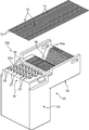
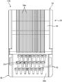
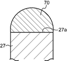
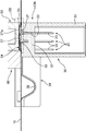
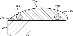
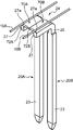
- 1 is an exploded perspective view of an electrical connection assembly according to a first embodiment of the present invention. It is a top view of the connector which comprises the said electrical connection assembly. It is a front view of the connector. It is a perspective view which shows the 1st connection member and the 2nd connection member which were fixed to the 1st terminal and 2nd terminal which comprise the said connector, and its electric wire connection surface. It is a cross-sectional front view which shows the said 1st connection member fixed to the electric wire connection surface of the said 1st terminal. It is a perspective view which shows the state which the said 1st and 2nd connection member was plastically deformed so that it might have a 1st protrusion part and a 2nd protrusion part, respectively.
- FIG. 8 is a front view showing a cross section taken along line VIII-VIII in FIG. 7. It is a perspective view which shows the state by which the 1st electric wire and the 2nd electric wire were mounted on the said 1st and 2nd connection member. It is a cross-sectional front view which shows the state of FIG. It is a perspective view which shows the process of connecting the electric wire connection surface of each terminal of the said connector, and the connection object site
- FIG. 12 is a cross-sectional side view showing the process shown in FIG. 11.
- FIG. 13 is an enlarged view of a region surrounded by a frame line XIII in FIG. 12.
- the perspective view which shows the state by which the conductors of the said 1st and 2nd electric wire were mutually connected through the said 1st and 2nd connection member by the fusion
- FIG. It is a cross-sectional front view which shows the state of FIG. It is a perspective view which shows the state in which the 1st electric wire and the 2nd electric wire were mounted on the said 1st and 2nd connection member, respectively. It is a cross-sectional front view which shows the state of FIG. The perspective view which shows the state by which the conductors of the said 1st and 2nd electric wire were mutually connected through the said 1st and 2nd connection member by the fusion
- the electrical connection assembly includes a plurality of electric wires 10 and a connector CN for connecting the plurality of electric wires 10 to another connector.
- 1 to 3 show the connector CN before the plurality of electric wires 10 are connected.
- Each of the plurality of electric wires 10 includes a conductor 12 and an insulating film 14 covering the conductor 12 as shown in FIGS. 10 and 13.
- the plurality of electric wires 10 are connected to the connector CN in a state of being arranged in parallel to each other with an interval in the electric wire arrangement direction orthogonal to the longitudinal direction.
- the electric wire used in the present invention may be a so-called bare electric wire that does not have the insulating coating 14.
- the plurality of electric wires 10 include a first electric wire 10A and a second electric wire 10B as shown in FIGS. These first and second electric wires 10A and 10B are electric wires adjacent to each other in the electric wire arrangement direction and are electrically connected to each other to form a branch circuit, that is, electric wires to be interconnected. It is. The structure and method for interconnecting the first and second electric wires 10A and 10B will be described in detail later.
- the connector CN includes a plurality of terminals 20 corresponding to each of the plurality of electric wires 10, an insulating housing 30 that collectively holds the plurality of terminals 20, and each of which is made of solder, and is provided to each of the plurality of terminals 20.
- Each of the plurality of terminals 20 is a male terminal composed of a single long metal plate, and includes a held portion 22, an electrical contact portion 23, and an outer side as shown in FIG.
- a protrusion 24 is provided.
- the held portion 22 is a portion held by the insulating housing 30 as described later.
- the electrical contact portion 23 is a male contact portion and has a shape that can be fitted to the female contact portion of the counterpart terminal. Specifically, it has a shape extending linearly from the held portion 22 in a first direction to be described later.
- the outer protruding portion 24 is a portion that protrudes from the held portion 22 to the opposite side of the electric contact portion 23 and is connected to the corresponding electric wire 10 among the plurality of electric wires 10. The outer protrusion 24 will be described in detail later.
- the plurality of terminals 20 include a first terminal 20A and a second terminal 20B corresponding to the first electric wire 10A and the second electric wire 10B, respectively, as shown in FIG.
- the first terminal 20A and the second terminal 20B are arranged adjacent to each other in the wire arrangement direction.
- the first electric wire 10A includes a first conductor 12A as the conductor
- the second electric wire 10B includes a second conductor 12B as the conductor.
- the insulating housing 30 is formed of an insulating material such as synthetic resin, and integrally includes a terminal holding portion 32, a hood 33, and an electric wire holding portion 34.
- the terminal holding portion 32 is a portion for holding the held portion 22 of each of the plurality of terminals 20, and is in a block shape in the first embodiment.
- the terminal holding portion 32 is configured to allow the electric wires 10 to be connected to the outer protrusions 24 of the plurality of terminals 20 in a conductive manner in a state where the electric wires 10 are arranged at intervals in the electric wire arrangement direction.
- the plurality of terminals 20 are collectively held in an arrangement in which the plurality of terminals 20 are arranged in the wire arrangement direction.
- the terminal holding part 32 holds the held part 22 of the terminal 20 in a state where each terminal 20 penetrates the terminal holding part 32 in a direction parallel to the first direction.
- the first direction is a direction orthogonal to both the longitudinal direction of the electric wire 10 and the electric wire arrangement direction in a state in which the electric wire 10 is connected to the terminal 20, and in the posture shown in FIG. is there. That is, in the posture shown in FIG. 12, a portion of the terminal 20 including the held portion 22 penetrates the terminal holding portion 32 in the vertical direction.
- the held portion 22 may be fixed to the terminal holding portion 32 by press-fitting the held portion 22 into a through hole provided in the terminal holding portion 32, or may be performed using an adhesive or the like. May be.
- each terminal 20 is in a direction opposite to the first direction (shown in FIG. 12) from the held portion 22 with the held portion 22 held by the terminal holding portion 32 as described above. In this posture, it extends downward) and fits in the direction with the female contact portion of the counterpart terminal.
- the hood 33 is integrally connected to the terminal holding portion 32 and has a cylindrical shape that surrounds the electrical contact portion 23 on the outer side in a direction orthogonal to the axial direction of the electrical contact portion 23 (vertical direction in the posture shown in FIG. 12). Make.
- the outer protrusion 24 of each terminal 20 integrally includes a first protrusion 26 and a second protrusion 27 as shown in FIGS.
- the first protruding portion 26 protrudes from the surface of the terminal holding portion 32 (upper surface 32a in FIG. 13) in the first direction (upward in FIG. 13).
- the second protrusion 27 is a second direction that is closer to the direction parallel to the surface of the terminal holding part 32 than the first direction from the upper end of the first protrusion 26 and is orthogonal to the wire arrangement direction. (In this first embodiment, it extends in the direction parallel to the upper surface 32a; the left-right direction in FIG. 13).
- connection surface 27a is so-called soldered to the connection target portion in a state where the connection target portion, which is a specific portion of the conductor 12 of the electric wire 10, is placed on the connection member 70 (that is, It is a surface that can be electrically connected (using the connection member 70 as a connection medium).
- the electric wire connection surface 27a according to the first embodiment extends in a direction parallel to the upper surface 32a of the terminal holding portion 32.
- the plurality of connection members 70 are fixed to the wire connection surfaces 27a of the plurality of terminals 20, respectively.
- the connection member 70 has a cross-sectional shape that bulges upward from the wire connection surface 27 a and is set on the wire connection surface 27 a so as to extend along the longitudinal direction of the wire 10.
- the plurality of connection members 70 include a first connection member 70 ⁇ / b> A applied to the first terminal 20 ⁇ / b> A and a second connection applied to the second terminal 20 ⁇ / b> B.
- Member 70B is shown in FIGS. 6 and 7, the plurality of connection members 70 include a first connection member 70 ⁇ / b> A applied to the first terminal 20 ⁇ / b> A and a second connection applied to the second terminal 20 ⁇ / b> B.
- the protrusion dimension from which the first protrusion 26 protrudes from the upper surface 32a of the terminal holding part 32 is appropriately set.
- the protruding dimension is a surface of the surface of the second protruding portion 27 that faces the upper surface 32a of the terminal holding portion 32, that is, a surface opposite to the wire connecting surface 27a.
- the second protrusion so that the second protrusion 27 extends in the second direction at a position where the inner side surface (lower surface in FIG. 13) 27b is spaced outward from the upper surface of the terminal holding portion 32 (upper side in FIG. 13).
- the dimension for setting the portion 27 is set.
- the protrusion dimension is set to the same dimension for all the terminals 20. Therefore, the terminal holding part 32 holds the terminal 20 so that the wire connection surfaces 27a of the terminals 20 are arranged on the same plane. Conversely, a specific height difference may be given between the electric wire connection surfaces 27a.
- the arrangement of the plurality of terminals 20 can be freely set.
- the electric wire connection surfaces 27a of the plurality of terminals 20 are arranged at intervals in the electric wire arrangement direction.
- the held portions 22 of the plurality of terminals 20 are held so that the wire connection surfaces 27a of the terminals 20 adjacent to each other in the arrangement direction are arranged with their positions shifted in the longitudinal direction of the wires 10 (vertical direction in FIG. 2). Specifically, in the arrangement shown in FIG.
- a plurality of outer protrusions 24 each having the electric wire connection surface 27a are arranged along three rows arranged in a direction parallel to the longitudinal direction of the electric wire 10, And the position of the electric wire connection surface 27a of the outer protrusion part 24 arrange
- column is each said electric wire arrangement direction with respect to the position of the electric wire connection surface 27a of the outer protrusion part 24 arrange
- the terminal holding portion 32 has a position of the wire connection surface 27a of the first terminal 20A and the wire connection surface of the second terminal 20B.
- the first and second terminals 20A and 20B are held at such positions that the positions are shifted in the longitudinal direction of the first and second electric wires 10A and 10B and the electric wire arrangement direction.
- the electric wire holding part 34 extends from the terminal holding part 32 along a direction parallel to the second direction, and each of the electric wires 10 extends in the posture in which the electric wires 10 extend along the second direction. Hold.
- the electric wire holding part 34 according to the first embodiment has a plurality of parallel electric wire holding grooves 34a corresponding to the electric wires 10, and the electric wires 10 are fitted in the electric wire holding grooves 34a.
- the electric wire 10 is supported from below in the state.
- the first connecting member 70A is provided with a shape including a first protruding portion 72A
- the second connecting member 70B is provided with a shape.
- 72 A of said 1st protrusion parts are the directions which approach the said 2nd electric wire 10B along the direction parallel to the said electric wire arrangement direction from the electric wire connection surface 27a of the said 1st terminal 20A (right direction in FIG. 6 and FIG. 8).
- the second protruding portion 72B extends from the electric wire connection surface 27a of the second terminal 20B toward the first electric wire 10A along a direction parallel to the electric wire arrangement direction (FIG. 6). It is the part that protrudes to the left).
- the protruding length of the first protruding portion 72A is set to a length that allows the second electric wire 10B to be placed on the first protruding portion 72A, as shown in FIGS. Has been.
- the protruding length of the second protruding portion 72B is set to a length that allows the first electric wire 10A to be placed on the second protruding portion 72B, as shown in FIG. Has been.
- the cross-sectional shapes of the first and second connection members 70A and 70B can be freely set.
- the first and second connection members 70A and 70B may have a rectangular cross section that is long in the lateral direction.
- the connector CN further includes a cover 40 as shown in FIG.
- the cover 40 is detachably attached to the insulating housing 30 so as to cover the outer protruding portion 24 of the terminal 20 and the electric wires 10 connected thereto from above.
- the cover 40 according to the first embodiment integrally includes a terminal cover portion 42 that covers the terminal holding portion 32 and an electric wire cover portion 44 that covers the electric wire holding portion 34.
- the electric wire holding portion 34 has a curved portion 36 that is curved so that the upper surface of the electric wire holding portion 34, that is, the surface on which the electric wire holding groove 34 a is formed is recessed downward at the intermediate position in the second direction.
- the lower surface of the wire cover portion 44 of the cover 40 has a curved portion 46 bulging downward corresponding to the curved portion 36.
- the bending portion 46 and the bending portion 36 have a shape capable of restraining the intermediate portion in a state where the intermediate portion of each electric wire 10 is bent downward. It effectively inhibits the tension of the electric wire 10 from acting on the connection portion between the 12 connection target portions and the electric wire connection surface 27a.
- the wire holding part 34 and the cover 40 are not essential in the present invention, and can be omitted. Conversely, when the connection target portion of the conductor 12 of each electric wire 10 is set not in the vicinity of the end of the electric wire 10 but in the intermediate portion in the longitudinal direction, on both sides of the terminal holding portion 32 in the longitudinal direction of the electric wire 10.
- the electric wire holding part 34 and the electric wire cover part 44 of the cover 40 corresponding thereto may be provided.
- the electrical connection assembly includes, for example, the following 1) electric wire preparation step, 2) connector preparation step, 3) terminal connection step and interconnection step (both steps are simultaneously executed in this embodiment), and 4) cutting. It can be manufactured by a method including steps.
- the several electric wire 10 mentioned above is prepared beforehand.
- the plurality of electric wires 10 are prepared such that the insulating coating 14 of each electric wire 10 is made of a specific synthetic resin.
- the specific synthetic resin is a synthetic resin that has an insulating property at room temperature and can be melted or decomposed at the melting temperature (for example, 380 to 400 ° C.) of the solder constituting the connecting member 70.
- the specific synthetic resin polyurethane, polyester, nylon and the like are suitable.
- the thickness of the insulating coating 14 is set to such a thickness that the insulating coating 14 can be removed and the conductor 12 can be exposed by the heating while ensuring an insulating state at room temperature. For the thickness, for example, a dimension approximating the thickness of the insulating coating in a normal enameled wire can be applied.
- This step includes the following 2-1) connecting member applying step, 2-2) terminal setting step, and 2-3) protruding portion forming step.
- connection member application step The connection members 70 are fixed to the electric wire connection surfaces 27a of the plurality of terminals 20 constituting the connector CN.
- the shape of the connecting member 70 at this stage can be freely set.
- the wire connecting surface 70 has a cross-sectional shape such that the central portion of the wire connecting surface 27 a rises in the width direction (direction parallel to the wire arranging direction). 27a is fixed.
- the connection member 70 may be applied to the terminal 20 by fixing the solder constituting the connection member 70 to the electric wire connection surface 27a in a solid state, or a paste-like solder (connection member). 70) may be applied to each electric wire connection surface 27a.
- Terminal setting step is a step of fixing the plurality of terminals 20 to the insulating housing 30, that is, a step of holding the plurality of terminals 20 in the insulating housing 30.
- the terminals 20 are inserted and press-fitted from above into a plurality of through holes formed in advance in the terminal holding portion 32 of the insulating housing 30 (that is, the through holes).
- the held portion 22 is bitten into the inner peripheral surface of the terminal holding portion 32 surrounding the terminal holding portion 32), or the held portion 22 is fixed to the terminal holding portion 32 by other means such as an adhesive.
- the plurality of terminals 20 are fixed to 32 predetermined positions, respectively.
- the terminal setting step may be performed before the connection member applying step. That is, the connection member 70 may be applied in a state where the plurality of terminals 20 are respectively held in the insulating housing 30. However, when the application of the connection member 70 is performed with heating of the connection member 70 (heating exceeding the melting point of the solder), the insulation housing 30 is in a state where the terminals 20 are already held by the insulation housing 30. Therefore, heat resistance sufficient to withstand the heating is required, and the material of the insulating housing 30 is restricted accordingly. Accordingly, the connecting member application step is performed before the terminal setting step, that is, the connection members 70 are applied to the plurality of terminals 20 before the plurality of terminals 20 are set in the insulating housing 30. Is more preferable.
- each connecting member 70 made of solder as described above can be easily generated by pressing a mold having an appropriate shape against the first and second connecting members 70A and 70B, for example. is there.
- the shape of the first and second protrusions 72A and 72B that is, the wire connection surface 27a of the first and second terminals 20A and 20B is parallel to the wire arrangement direction. It is possible to freely set a shape that protrudes in any direction.
- This protruding portion forming step may be performed before or simultaneously with the terminal setting step and the connecting member applying step.
- the protrusions 72A and 72B may be formed after the connection member 70 is applied to each terminal 20 and before the terminal 20 is held by the insulating housing 30, or the first and second protrusions are already formed.
- the first and second connection members 70A and 70B in which the portions 72A and 72B are formed may be fixed to the wire connection surfaces 27a of the first and second terminals 20A and 20B.
- the protruding portion forming step is performed after the connection member applying step and the terminal setting step, that is, the positioning of the plurality of terminals 20 with respect to the insulating housing 30 by holding the plurality of terminals 20 by the insulating housing 30 and Forming the protruding portions 72A and 72B in a state where the plurality of terminals 20 are already positioned means that the protruding portions 72A and 72B and the first and second electric wires 10A to be connected to the protruding portions 72A and 72B. , 10B can be more reliably positioned.
- the protruding portion forming step is performed only on the connection member corresponding to the wire to be interconnected among the plurality of connection members.
- the electrical connection assembly provided by the present invention may include a plurality of interconnected wire pairs (a pair of wires to be interconnected), in which case each interconnected wire is It is preferable that the protruding portion forming step is performed for the corresponding connecting member.
- Terminal connection process and interconnection process In the terminal connection process, the plurality of wires 10 are brought into contact with the plurality of connection members 70 in a state in which the plurality of wires 10 are arranged at intervals in the wire arrangement direction. While the plurality of connection members 70 are heated and melted, the connection target portions set in the respective conductors 12 of the plurality of wires 10 and the corresponding wire connection surfaces 27a are connected to the plurality of connection members. 70, and the interconnecting step includes first and second protruding portions 72A of the first and second connecting members 70A and 70B of the plurality of connecting members 70, By heating and melting 72B, the conductor 12A of the first electric wire 10A and the second electric wire are mediated by the first and second connecting members 70A and 70B. This is a step of connecting the 10B conductor 12B to each other.
- the terminal connection process and the interconnection process are performed simultaneously. Specifically, both the connecting steps are performed by sequentially performing the following 3-1) wire setting work and 3-2) heating work.
- Electric wire setting operation This operation is performed while maintaining the state in which the plurality of electric wires 10 are arranged at intervals in the electric wire arrangement direction as shown in FIG. This is an operation of bringing the connection target portion set in the intermediate direction region into contact with the surfaces of the plurality of connection members 70 in a state where the connection target portion is covered with the insulating coating 14.
- the plurality of electric wires 10 are held at positions on both outer sides of the connection target part, more preferably both ends of the connector CN in the front-rear direction (the second direction and the direction parallel to the electric wire longitudinal direction). This is done by holding the outer position. In the holding, it is preferable that the electric wire 10 is fitted into the protruding portions 72A and 72B while an appropriate tension is applied to each of the plurality of electric wires 10.
- the holding can be performed by, for example, a bobbin around which the plurality of electric wires 10 are wound, a holding tool that holds the electric wires 10 from both sides in a direction orthogonal to both the longitudinal direction and the electric wire arrangement direction, and the like. is there.
- the first connecting member 70A among the plurality of connecting members 70 is a second protruding portion 72A, that is, the second from the wire connecting surface 27a corresponding to the first connecting member 70A.
- a portion protruding in a direction parallel to the electric wire arrangement direction toward the electric wire 10B, and the second connecting member 70B is a second protruding portion 72B, that is, the electric wire connecting surface 27a corresponding to the second connecting member 70B.
- the second electric wire 10 ⁇ / b> B not only contacts the corresponding second connecting member 70 ⁇ / b> B but also from the second connecting member 70 ⁇ / b> B to the first and second It is possible to contact the first protruding portion 72A of the first connecting member 70A at a position shifted in the longitudinal direction of the electric wires 10A and 10B, and the first electric wire 10A corresponds to this. It is possible not only to contact the first connecting member 70A but also to contact the second protruding portion 72B of the second connecting member 70B at a position shifted from the first connecting member 70A in the longitudinal direction. To do.
- connection member 70 is used as an intermediary to electrically connect the connection target portion and the wire connection surface 27a of the terminal 20 corresponding thereto.
- a portion of the insulating coating 14 of each electric wire 10 that covers the connection target portion of the conductor 12 is heated together with the connection member 70, thereby melting the insulating coating 14 covering the connection target portion.
- the removal from the surface of the conductor 12 by disassembly and the conductor 12 exposed by the removal of the insulating coating 14 and the wire connection surface 27a to which the connection member 70 is fixed via the connection member 70). Electrical connection is achieved at the same time. In this way, the terminal connection process for each terminal 20 is executed.
- the pressing and heating of the electric wire 10 against the electric wire connecting surface 27a can be efficiently performed using the heater 50 shown in FIGS.
- the heater 50 has a flat lower surface constituting the heating surface 52.
- the heating surface 52 is pressed against the electric wires 10 set on the electric wire connection surfaces 27a via the connection members 70, that is, the heating surface 52 and the electric wire connection surfaces 27a.
- the heating surface 52 is pressed toward the plurality of wire connection surfaces 27a with the plurality of connection target portions and the connection member 70 respectively sandwiched between the plurality of wire connection surfaces 27a.
- the melting by heating of the connection member 70 by the heater 50 and the melting or decomposition of the insulating coating 14 by heating of the insulating coating 14 covering the connection target site are performed simultaneously. Melting or decomposing the insulating coating 14 allows the insulating coating 14 to be removed from the surface of the conductor 12.
- the terminal holding part 32 of the insulating housing 30 holds the terminals 20 so that the electric wire connection surfaces 27a are arranged on the same plane, that is, the terminals 20 are the plane array terminals.
- the plurality of connecting members 70 are simultaneously and uniformly heated using a single flat heating surface 52, and the connection target portions of the conductors 12 of each wire 10 and the conductor 12 of each wire 10 are Can be performed simultaneously.
- each said wire connection surface 27a is provided in the outer side protrusion part 24 which protrudes on the outer side (in FIG. 13 etc.) of the said terminal holding part 32 from the upper surface 32a of the terminal holding part 32.
- the first connecting member 70A is heated by the heater 50, as shown in FIGS. 14 and 15, the first electric wire 10B out of the second electric wires 10B.
- the insulating coating 14 at the portion of the connecting member 70A that contacts the first protruding portion 72A is also removed, and the conductor 12B of the second electric wire 10B is held in direct contact with the first protruding portion 72A.
- the second connecting member 70B is heated by the heater 50, the insulating coating 14 at a portion of the first electric wire 10A that contacts the second protruding portion 72B of the second connecting member 70B is also provided.
- the conductor 12A of the first electric wire 10A is removed and is held in direct contact with the second protruding portion 72B.
- the first connecting member 70A is fixed to the conductor 12A of the first electric wire 10A corresponding to the first connecting member 70A, and at a position away from the electric wire connecting surface 27a of the first terminal 20A in the electric wire longitudinal direction.
- the first protruding portion 72A is also fixed to the conductor 12B of the second electric wire 10B.
- the second connecting member 70B is fixed to the corresponding conductor 12B of the second electric wire 10B.
- the second protruding portion 72B is also fixed to the conductor 12A of the first electric wire 10A at a position away from the electric wire connecting surface 27a of the second terminal 20B in the electric wire longitudinal direction.
- the first and second electric wires 10A and 10B can be connected to each other by using the first and second connecting members 70A and 70B as they are as connection media without adding any special members.
- An interconnect process is performed.
- a cover 40 as shown in FIG. 16 is attached as necessary to complete the electrical connection assembly. Note that the cutting step and the attachment of the cover 40 are not essential in the present invention, and can be omitted as appropriate.
- the second connecting member 70B in addition to the first protruding portion 72A being formed on the first connecting member 70A and being fixed to the second electric wire 10B, the second connecting member 70B also has the second protruding portion 72A.
- the protruding portion 72B is formed and fixed to the first electric wire 10A, the first and second electric wires 10A and 10B can be interconnected only by connecting the first protruding portion 72A and the second electric wire 10B. Is possible.
- the double connection through the first and second protrusions 72A and 72B significantly improves the reliability of the interconnection.
- the first protruding portion 72A has a shape that extends further in the electric wire arrangement direction than the above shape, thereby being fixed to the conductor of the third electric wire further adjacent to the second electric wire 10B. Is also possible. This makes it possible to interconnect three or more wires via the first connecting member 70A. In other words, the present invention broadly encompasses those in which at least the first and second electric wires are interconnected using the first connecting member.
- a connector CN similar to the connector CN shown in FIGS. 1 to 3 and a plurality of electric wires 10 are used, and a connector preparation process, a terminal connection process, and an interconnection process are performed. It is done in order.
- the first and second connecting members 70A and 70B are connected to the mating electric wires (second electric wires 10B from the respective electric wire connecting surfaces 27a. And the 1st and 2nd protrusion parts 72A and 72B which protrude toward the 1st electric wire 10A) are formed.
- the second embodiment is different from the first embodiment in the following points.
- the wire connection surfaces 27a of the first and second terminals 20A and 20B adjacent in the wire arrangement direction are in a position shifted in the wire longitudinal direction, and the interconnection step.
- the first and second protruding portions 72A and 72B formed on the first and second connection members 70A and 70B are directly fixed to the conductors 12B and 12A of the second and first electric wires 10B and 10A, respectively.
- the first and second terminals 20A and 27B are arranged in a direction parallel to the electric wire arrangement direction, and the first and second protruding portions 72A.
- the first and second electric wires 10A are respectively connected to the first and second connecting members 70A and 70B as shown in FIGS. , 10B, the first and second electric wires 10A, 10B are set.
- the first and second connection members 70A and 70B are heated and melted, whereby the first and second connection members 70A and 70B are integrated with each other, as shown in FIGS.
- a single interconnection member 74 is configured, and the conductors 12A and 12B of the first and second electric wires 10A and 10B are electrically connected to each other through the interconnection member 74.
- first and second connecting members 70A and 70B are not integrated with each other, and the first and second protruding portions 72A and 72B are in contact with each other, so that the interconnection is achieved. Is possible. However, the formation of the interconnection member 74 by the integration dramatically increases the reliability of the interconnection.
- the ends of the first and second protruding portions 72A and 72B may be arranged so as to overlap each other in the thickness direction (the vertical direction in the postures according to the first and second embodiments). Or only the 1st protrusion part 72A of the 1st and 2nd protrusion parts 72A and 72B is formed, and the 1st protrusion part 72A only makes it possible to contact the 2nd connection member 70B.
- the overhang length may be given to the first overhang portion 72A.
- the counterpart to which the first protruding portion 72A is fixed is not limited to the second connecting member 70B, but may be, for example, an appropriate portion of the second terminal 20B (for example, the side surface of the second protruding portion 27). Good.
- the present invention includes the following other forms.
- the shape of the protruding portion formed at least on the first connecting member is not limited to those shown in the first and second embodiments, and is arbitrarily set. Is possible.
- the protruding portion may be provided with a shape for stabilizing the relative position between the protruding portion and the electric wire in contact with the protruding portion, for example, a shape including a groove into which the electric wire can be fitted.
- the direction in which the protruding portion protrudes from the electric wire connection surface is not necessarily limited to the direction parallel to the electric wire arrangement direction.
- the first protruding portion 72A may extend obliquely with respect to the electric wire arrangement direction so that the first protruding portion 72A contacts the second connecting member 70B or the second terminal 20B.
- the first protruding portion 72A can be fixed to the conductor 12B of the second electric wire 10B at a position away from the second connecting member 70B and the second terminal 20B in the electric wire longitudinal direction.
- the first protruding portion 72A may extend obliquely with respect to the electric wire arrangement direction.
- the terminal connection process and the interconnection process may be performed individually instead of simultaneously.
- the first connection member 70A according to the first embodiment is mediated by the first connection member 70A by local heating of a portion located immediately above the wire connection surface 27a of the first terminal 20A.
- the first protruding portion is locally heated by the first protruding portion 72A of the first connecting member 70A.
- the connection between 72A and the conductor 12B of the second electric wire 10B may be performed.
- the terminal connection step may be performed for each terminal 20 individually. That is, the plurality of connection members 70 may be individually heated. Alternatively, when a plurality of connection members 70 exist, the connection members 70 may be heated for each group divided in advance.
- connection between the wire connection surface and the connection target portion the conductor 12 is melted or decomposed simultaneously with the melting of the connection member 70 by heating with a heater.
- the removal from the surface is performed, the removal of the insulating coating 14 may be performed in advance before the heating. That is, the insulating coating is removed in advance before the connecting step by a so-called skinning process so as to expose the connection target portion of the conductor set in each of the plurality of electric wires, and the conductor exposed as described above in the connecting step Soldering with an electric wire connection surface may be performed directly.
- the material constituting the insulating coating does not necessarily have to be melted or decomposed. Needless to say, it is not necessary to remove the insulation coating when each wire is a bare wire.
- the number of wires in the electrical connection assembly according to the present invention is not limited.
- the present invention can be widely applied to an electrical connection assembly including a plurality of electric wires, wherein the plurality of electric wires include at least a first electric wire and a second electric wire (which are to be interconnected). is there.
- an electrical connection assembly including a plurality of wires and connectors, and a desired structure of the plurality of wires can be achieved with a simple structure without significant increase in cost.
- those capable of interconnecting the conductors of an electrical wire and methods that enable the electrical connection assembly to be efficiently manufactured are provided.
- connection member which is a connection medium for connecting the first electric wire and the corresponding first terminal, approaches the second electric wire from the electric wire connection surface of the first terminal.
- connection member By providing a shape that protrudes in the direction, the connection member can be used as a connection medium for connecting the first electric wire and the second electric wire, so that no special member is required. Interconnection of the first electric wire and the second electric wire can be achieved with a simple structure.
- the protruding portion of the first connecting member is directly fixed to the conductor of the second electric wire.
- the first connecting member is directly fixed to both conductors of the first and second electric wires, that is, only the first connecting member is used as a medium for the first and second electric wires.
- the position of the wire connection surface of the first terminal and the position of the wire connection surface of the second terminal are such that the first wire and the second wire are displaced in the longitudinal direction of the first wire.
- the protruding portion of the connection member applied to the first terminal is parallel to the wire arrangement direction from the wire connection surface of the first terminal. It is preferable that it protrudes in any direction and is directly fixed to the conductor of the second electric wire. Accordingly, the first and second terminals are provided with a sufficient distance between the first terminal and the second terminal due to mutual displacement of the positions of the first and second terminals in the longitudinal direction.
- the protruding length of the protruding portion for interconnecting the two electric wires can be kept small.
- the second connecting member has a protruding portion that protrudes in a direction approaching the first electric wire from the electric wire connecting surface of the second terminal.
- the protruding portion of the connecting member may be directly fixed to the conductor of the first electric wire. Such double connection further increases the reliability of the interconnection between the first electric wire and the second electric wire.
- the protruding portion of the first connecting member protrudes in the direction from the electric wire connecting surface of the first terminal toward the second terminal, and is fixed to the second terminal or the second connecting member. It may be a thing. Also in this case, it is possible to connect the first electric wire and the second electric wire to each other through the first connecting member and further the second connecting member.
- first connecting member and the second connecting member can be integrated with each other to form a single interconnect member, for example, by melting them and then solidifying them. This drastically improves the connection reliability as compared with the aspect in which the first and second connection members are simply in contact with each other.
- the method provided by the present invention includes a plurality of electric wires and connectors each including a conductor, and the first electric wire and the second electric wire included in the plurality of electric wires are connected to each other.
- a method for manufacturing a connection assembly wherein the connector includes a plurality of terminals corresponding to each of the plurality of electric wires, the first terminals corresponding to the first electric wires, and the second electric wires.
- a second connection member including a corresponding second terminal, a plurality of connection members each formed of solder and applied to each of the plurality of terminals, the first connection member applied to the first terminal, and the The connection member including the second connection member provided to the second terminal and the plurality of wires in a state in which the plurality of wires are arranged at intervals in the wire arrangement direction orthogonal to the longitudinal direction thereof.
- An insulating housing that collectively holds the plurality of terminals in an arrangement in which the plurality of terminals are arranged in the electric wire arrangement direction so as to be connected to each other.
- connection object set in each conductor of the plurality of electric wires by heating and melting the plurality of connection members while bringing the plurality of electric wires into contact with the plurality of connection members in a state of being arranged
- connection by a simple operation of heating and melting each of the plurality of connecting members, the connection between the plurality of electric wires and the corresponding terminals (terminals) through the plurality of connecting members is performed. Connection) and interconnection between the conductor of the first electric wire and the conductor of the second electric wire through the first connecting member can be efficiently performed.
- the terminal connection step for connection between the first electric wire and the first terminal through the first connection member it is also possible to carry out the interconnection step simultaneously, which can further improve the production efficiency of the electrical connection assembly as compared with the case where the terminal connection step and the interconnection step are performed separately.
- the protrusion is made to protrude from the first connection member by plastically deforming the first connection member in a state where the first connection member is fixed to the electric wire connection surface of the first terminal. It is preferable to include forming a part. In this method, a protruding portion having a preferable shape can be easily formed by plastically deforming the connection member using the characteristics of the solder constituting the connection member.
- the protruding portion is formed after the plurality of terminals are held by the insulating housing. This further ensures the positioning of the protruding portion with respect to the first electric wire.
- the protruding portion of the first connecting member is prepared to have a shape that allows direct contact with the conductor of the second electric wire.
- the protruding portion is It is preferable that the protruding portion is heated and directly fixed to the conductor of the second electric wire in a state of being in direct contact with the second electric wire.
- the first connecting member is directly fixed to the conductor of the second electric wire by a simple operation of heating the protruding portion in a state where the protruding portion and the second electric wire are in contact with each other. That is, it is possible to directly interconnect the first electric wire and the second electric wire with the first connecting member as a medium, thereby obtaining high reliability for the interconnection. it can.
- the position of the wire connection surface of the first terminal and the position of the wire connection surface of the second terminal are shifted from each other in the longitudinal direction of the first wire and the second wire.
- the protruding portion of the connecting member held by the first housing and the second terminal in the insulating housing at a certain position and applied to the first terminal extends from the wire connection surface of the first terminal to the wire arrangement.
- a protruding part is prepared in a direction parallel to the direction, and the protruding part is fixed to the conductor of the second electric wire at a position deviating from the electric wire connecting surface of the second terminal in the longitudinal direction in the interconnection step.
- first and second terminals may be provided with a sufficient distance between the first terminal and the second terminal by the mutual displacement of the positions of the first and second terminals in the longitudinal direction.
- Second wire interconnection Possible to reduce the protrusion length of the protruding portion for are possible.
- an protruding portion that protrudes in a direction in which the second connecting member approaches the first electric wire from the electric wire connecting surface of the second terminal is provided.
- the protruding portion of the second connecting member may be directly fixed to the conductor of the first electric wire in the interconnection step. Such double connection further increases the reliability of the interconnection between the first electric wire and the second electric wire.
- the protruding portion of the first connecting member is prepared to protrude in the direction from the electric wire connecting surface of the first terminal toward the second terminal.
- the protruding portion is It may be fixed to the second terminal or the second connecting member by being heated and melted. Also in this method, the first electric wire and the second electric wire can be connected to each other through the first connecting member and the second connecting member as a simple operation by simply heating the protruding portion. It is possible to connect.
- first connection member and the second connection member are integrated with each other by heating and melting both the first connection member and the second connection member. It is possible to form an interconnection member, thereby connecting the first electric wire and the second electric wire with higher connection reliability than the aspect in which the first and second connection members are simply in contact with each other. can do.
- the second terminal is provided in the second connection member.
- a protruding portion protruding from the electric wire connection surface toward the first connecting member is formed, and the protruding portions are mutually connected by heating both the protruding portions of the first connecting member and the second connecting member. It is also possible to form the interconnection member integrally. According to this method, even when there is a distance between the first terminal and the second terminal, the first electric wire is suppressed while keeping the protruding length of each protruding portion of the first and second connecting members small. And the conductor of the second electric wire can be interconnected with high reliability.
Landscapes
- Engineering & Computer Science (AREA)
- Manufacturing & Machinery (AREA)
- Manufacturing Of Electrical Connectors (AREA)
- Connections Effected By Soldering, Adhesion, Or Permanent Deformation (AREA)
Abstract
簡素な構造で第1及び第2の電線(10A,10B)の導体同士の相互接続が可能な電気接続アセンブリ及びその製造方法が提供される。電気接続アセンブリは、第1及び第2の電線(10A,10B)を含む複数の電線と、第1及び第2の電線(10A,10B)に対応する第1及び第2の端子(20A,20B)を含む複数の端子と、はんだからなり、第1及び第2の端子(20A,20B)の電線接続面(27a)に固着される第1及び第2の接続部材(70A,70B)を含む複数の接続部材と、前記複数の端子を保持する絶縁ハウジングと、を備える。第1の接続部材(70A)は、第1の端子(20A)の電線接続面(27a)からはみ出して第2の電線(10B)の導体に電気的に接続されるはみ出し部(72A)を有する。
Description
本発明は、自動車等に使用される電気接続アセンブリ及びこれを製造するための方法に関する。
自動車等に用いられる配線材として、複数本の電線がその軸方向と直交する特定方向に配列された偏平状のものが知られている。当該配線材に含まれる前記複数本の電線を他の回路に接続する手段として、当該複数本の電線を端子及びハウジングを含むコネクタの当該端子に接続することが、行われる。
前記のように配列された複数本の電線及びこれに接続されるコネクタを備えたアセンブリであって、当該接続がはんだ付けによって行われるものが特許文献1に記載されている。当該特許文献1に記載されるコネクタは、複数の電線のそれぞれに対応する薄板状の複数の端子と、当該複数の端子を保持するハウジングと、を備える。当該ハウジングは平坦な端子配列面を有し、当該端子配列面上で前記複数の端子が露出するように当該複数の端子を保持する。一方、複数本の電線のそれぞれの端末では予め絶縁被覆が除去されて導体が露出しており、当該導体の先端が一列に揃うように前記複数本の電線が当該先端に近い部位で保持される。
前記コネクタにおいて、前記端子の表面に予めクリームはんだがセットされており、前記複数本の端子のそれぞれの導体の先端が前記クリームはんだ上に位置決めされた状態でヒータにより前記端子の表面に押圧されかつ前記クリームはんだが加熱されることにより、当該導体の先端と前記端子の表面とのはんだ付けが行われる。
前記のように複数の電線及びコネクタを備えた電気接続アセンブリにおいては、当該複数の電線を外部の回路に接続するだけでなく、当該複数の電線のうちの特定の電線同士を相互接続すること、換言すれば、分岐回路を形成すること、が要求される場合がある。このような相互接続は、例えば、(i)特許文献1に記載される複数の端子のうちの特定の端子同士を専用の接続部材を介して相互接続すること、(ii)当該複数の端子のうちの特定の端子を分岐回路形成のための専用の特殊な端子に置き換えること、あるいは、(iii)コネクタから離れた位置で特定の電線同士を当該コネクタとは独立した専用構造にてスプライス接続すること、が考えられる。
しかし、(i)~(iii)のいずれの方法も、通常仕様の端子とは別の相互接続専用の特殊部品を要することになり、著しいコスト高は免れ得ない。また、製造面においても、(i)及び(iii)の方法は著しい工数の増大を伴い、また(ii)の方法は特殊端子を含む複数の端子の管理の複雑化を伴う。これらはいずれも生産効率の向上の妨げとなる。
本発明は、複数本の電線及びコネクタを備えた電気接続アセンブリであって、著しいコストの増加を伴うことのない簡素な構造で前記複数本の電線のうちの所望の電線の導体同士を相互に接続することが可能なもの、及び当該電気接続アセンブリを効率よく製造することを可能にする方法を提供することを目的とする。
本発明者らは、当該目的を達成する手段として、前記複数の電線とこれらに対応する端子とを接続するための媒体である接続部材に着目した。当該接続部材は、はんだにより構成されるために形状の自由度が高い。よって、当該形状を工夫することにより、特別な部材を付加することなく、特定の電線の導体同士を相互に接続することが可能である。
本発明は、このような観点からなされたものである。本発明により提供される電気接続アセンブリは、それぞれが導体を含む複数の電線と、前記複数の電線のそれぞれに対応する複数の端子と、はんだからなり、前記複数の端子のそれぞれに付与される複数の接続部材と、前記複数の電線がその長手方向と直交する電線配列方向に間隔をおいて並んだ状態で前記複数の端子にそれぞれ前記接続部材を介して導通可能に接続されることを可能にするように前記複数の端子が前記電線配列方向に並ぶ配列で前記複数の端子を一括して保持する絶縁ハウジングと、を備える。前記複数の端子のそれぞれは、前記複数の電線の導体のそれぞれと接続可能な電線接続面を有し、当該電線接続面上に前記接続部材が固着される。前記複数の電線は、相互に電気接続される第1の電線及び第2の電線を含み、前記複数の端子は前記第1の電線及び前記第2の電線にそれぞれ対応する第1の端子及び第2の端子を含み、前記複数の接続部材は前記第1の端子に付与される第1の接続部材及び前記第2の端子に付与される第2の接続部材を含む。前記第1の接続部材は、前記第1の端子の電線接続面から前記第2の電線に近づく向きにはみ出して当該第2の電線の導体に電気的に接続されるはみ出し部を有する。
本発明の好ましい実施の形態を、図面を参照しながら説明する。
図1~図16は本発明の第1の実施の形態に係る電気接続アセンブリ及びその製造方法を示す。前記電気接続アセンブリは、複数本の電線10と、当該複数本の電線10を他のコネクタに接続するためのコネクタCNと、を備える。図1~図3は前記複数本の電線10が接続される前の前記コネクタCNを示す。
前記複数本の電線10のそれぞれは、図10及び図13にも示すように、導体12と、当該導体12を被覆する絶縁被膜14と、を有する。前記複数本の電線10は、その長手方向と直交する電線配列方向に間隔をおいて互いに平行に並んだ状態で前記コネクタCNに接続される。本発明において用いられる電線は、前記絶縁被膜14を有しない、いわゆる裸電線であってもよい。
前記複数本の電線10は、図9及び図10に示されるような第1の電線10A及び第2の電線10Bを含む。これら第1及び第2の電線10A,10Bは、前記電線配列方向に隣り合う電線であって、互いに電気的に接続されて分岐回路を構成するための電線、つまり、相互接続の対象となる電線である。当該第1及び第2の電線10A,10Bを相互接続するための構造及び方法については後に詳述する。
前記コネクタCNは、前記複数の電線10のそれぞれに対応する複数の端子20と、当該複数の端子20をまとめて保持する絶縁ハウジング30と、それぞれがはんだからなり、前記複数の端子20にそれぞれ付与される複数の接続部材70と、を備える。
この実施の形態に係る前記複数の端子20のそれぞれは、単一の長尺な金属板により構成された雄型端子であり、図4に示すような被保持部22、電気接触部23及び外側突出部24を有する。前記被保持部22は後述のように前記絶縁ハウジング30に保持される部位である。前記電気接触部23は、この第1の実施の形態では雄型の接触部であって相手方端子の雌型の接触部と嵌合可能な形状を有する。具体的には、前記被保持部22から後述の第1方向に直線状に延びる形状を有する。前記外側突出部24は、前記被保持部22から前記電気接触部23と反対側に突出して前記複数の電線10のうちの対応する電線10に接続される部位である。当該外側突出部24については後に詳述する。
前記複数の端子20は、図9に示されるように前記第1の電線10A及び前記第2の電線10Bにそれぞれ対応する第1の端子20A及び第2の端子20Bを含む。当該第1の端子20A及び当該第2の端子20Bは前記電線配列方向に隣り合うように配置されている。図10に示されるように、前記第1の電線10Aは前記導体として第1の導体12Aを含み、前記第2の電線10Bは前記導体として第2の導体12Bを含む。
前記絶縁ハウジング30は、合成樹脂等の絶縁材料により成形されたもので、端子保持部32と、フード33と、電線保持部34と、を一体に有する。
前記端子保持部32は、前記複数の端子20のそれぞれの前記被保持部22を保持する部位であり、この第1の実施の形態ではブロック状をなす。当該端子保持部32は、電線10が前記の電線配列方向に間隔をおいて並んだ状態で前記複数の端子20の外側突出部24にそれぞれ導通可能に接続されることを可能にするように前記複数の端子20が前記電線配列方向に並ぶ配列で当該複数の端子20を一括して保持する。
具体的に、当該端子保持部32は、当該端子保持部32を前記各端子20が前記第1方向と平行な方向に貫通する状態で当該端子20の被保持部22を保持する。前記第1方向は、前記端子20に前記電線10が接続された状態において当該電線10の長手方向及び電線配列方向の双方に対して直交する方向であり、図12に示される姿勢では上方向である。つまり、図12に示される姿勢において前記端子20のうち前記被保持部22を含む部分が前記端子保持部32を上下方向に貫通する。当該端子保持部32への当該被保持部22の固定は、当該端子保持部32に設けられた貫通孔への当該被保持部22の圧入により行われてもよいし、接着剤等により行われてもよい。
前記各端子20の電気接触部23は、前記のように被保持部22が前記端子保持部32に保持された状態で当該被保持部22から前記第1方向と反対の方向(図12に示される姿勢では下方向)に延び、当該方向に前記相手方端子の雌型接触部と嵌合する。前記フード33は、前記端子保持部32と一体につながり、前記電気接触部23の軸方向(図12に示される姿勢では上下方向)と直交する方向の外側で当該電気接触部23を囲む筒状をなす。
前記各端子20の外側突出部24は、図4,図5及び図13に示すような第1突出部26及び第2突出部27を一体に有する。前記第1突出部26は、前記端子保持部32の表面(図13では上面32a)から前記第1方向(図13では上方向)に突出する。前記第2突出部27は、前記第1突出部26の上端から前記第1方向よりも前記端子保持部32の表面と平行な方向に近い方向であって前記電線配列方向と直交する第2方向(この第1の実施の形態では前記上面32aと平行な方向;図13では左右方向)に延びる。
前記第2突出部27の表面のうち、前記端子保持部32の表面(図13では上面32a)と反対側の面である外側面(図13では上面)は電線接続面27aを構成する。当該電線接続面27aは、その上に前記電線10の導体12の特定の部位である接続対象部位が前記接続部材70を介して載せられた状態で当該接続対象部位といわゆるはんだ付けにより(つまり前記接続部材70を接続媒体として)電気的に接続されることが可能な面である。この第1の実施の形態に係る電線接続面27aは、前記端子保持部32の上面32aと平行な方向に延びる。
前記複数の接続部材70は、前記複数の端子20の電線接続面27aにそれぞれ固着される。当該接続部材70は、前記電線接続面27aから上向きに膨出するような断面形状を有し、前記電線10の長手方向に沿って延びるように前記電線接続面27aの上にセットされている。当該複数の接続部材70は、図6及び図7に示すように、前記第1の端子20Aに付与される第1の接続部材70Aと、前記第2の端子20Bに付与される第2の接続部材70Bと、を含む。
前記第1突出部26が前記端子保持部32の上面32aから突出する突出寸法は、適宜設定される。この第1の実施の形態では、前記突出寸法は、前記第2突出部27の表面のうち前記端子保持部32の上面32aと対向する面、つまり前記電線接続面27aと反対側の面である内側面(図13では下面)27b、が当該端子保持部32の上面から外側(図13では上側)に離間した位置で前記第2突出部27が前記第2方向に延びるように当該第2突出部27を位置させる寸法に設定されている。当該突出寸法は、全ての端子20について同一の寸法に設定されている。従って、当該端子保持部32は、前記各端子20の電線接続面27aが同一平面上に並ぶように当該端子20を保持する。逆に、当該電線接続面27a同士の間に特定の高低差が与えられてもよい。
前記複数の端子20の配列も自由に設定されることが可能である。この第1の実施の形態に係る端子保持部32は、前記複数の端子20の前記電線接続面27aが前記電線配列方向に間隔をおいて並ぶのに加え、前記複数の端子20のうち前記電線配列方向に隣接する端子20の電線接続面27aが前記電線10の長手方向(図2の上下方向)に互いに位置をずらして並ぶように、当該複数の端子20の被保持部22を保持する。具体的に、図2に示される配列では、それぞれが前記電線接続面27aをもつ複数の外側突出部24が前記電線10の長手方向と平行な方向に並ぶ3本の列に沿って配列され、かつ、各列に配置される外側突出部24の電線接続面27aの位置が当該列に隣接する列に配置される外側突出部24の電線接続面27aの位置に対して前記電線配列方向にそれぞれずれている。
従って、この実施の形態に係る前記端子保持部32は、図9及び図10に示すように、前記第1の端子20Aの電線接続面27aの位置と前記第2の端子20Bの電線接続面の位置とが前記第1及び第2の電線10A,10Bの長手方向及び前記電線配列方向にずれるような位置に当該第1及び第2の端子20A,20Bを保持する。
前記電線保持部34は、前記端子保持部32から前記第2方向と平行な方向に沿って延び、前記複数の電線10のそれぞれを当該複数の電線10が前記第2方向に沿って延びる姿勢で保持する。この第1の実施の形態に係る電線保持部34は、前記各電線10に対応した複数本の平行な電線保持溝34aを有し、当該電線保持溝34aに前記各電線10が嵌まり込んだ状態で当該電線10を下から支持する。
さらに、このコネクタCNの特徴として、図6~図8に示すように、前記第1の接続部材70Aには、第1のはみ出し部72Aを含む形状が与えられ、前記第2の接続部材70Bには、第2のはみ出し部72Bを含む形状が与えられている。前記第1のはみ出し部72Aは、前記第1の端子20Aの電線接続面27aから前記電線配列方向と平行な方向に沿って前記第2の電線10Bに近づく向き(図6及び図8では右向き)にはみ出す部分であり、前記第2のはみ出し部72Bは、前記第2の端子20Bの電線接続面27aから前記電線配列方向と平行な方向に沿って前記第1の電線10Aに近づく向き(図6では左向き)にはみ出す部分である。
前記第1のはみ出し部72Aのはみ出し長さは、図9及び図10に示すように、当該第1のはみ出し部72Aの上に前記第2の電線10Bが載ることを可能にする長さに設定されている。同様に、前記第2のはみ出し部72Bのはみ出し長さは、図9に示すように、当該第2のはみ出し部72Bの上に前記第1の電線10Aが載ることを可能にする長さに設定されている。これらの条件を満たす範囲で、前記第1及び第2の接続部材70A,70Bの断面形状は自由に設定されることが可能である。例えば、当該第1及び第2の接続部材70A,70Bは、横方向に長い矩形状の断面を有していてもよい。
この実施の形態に係る前記コネクタCNは、さらに、図16に示すようなカバー40を備える。当該カバー40は、前記端子20の外側突出部24及びこれに接続される前記各電線10を上から覆うように前記絶縁ハウジング30に着脱可能に装着される。具体的に、この第1の実施の形態に係るカバー40は、前記端子保持部32を覆う端子カバー部42と、前記電線保持部34を覆う電線カバー部44と、を一体に有する。
前記電線保持部34は、当該電線保持部34の上面すなわち前記電線保持溝34aが形成される面が前記第2方向の中間位置において下向きに凹むように湾曲する湾曲部36を有する。一方、前記カバー40の電線カバー部44の下面は、前記湾曲部36に対応して下向きに膨出する湾曲部46を有する。当該湾曲部46と前記湾曲部36は、前記各電線10の中間部位を下向きに湾曲させた状態で当該中間部位を拘束することが可能な形状を有し、これにより、当該各電線10の導体12の接続対象部位と前記電線接続面27aとの接続箇所に電線10の張力が作用することを有効に抑止する。
前記電線保持部34及び前記カバー40は本発明において必須のものではなく、省略されることが可能である。逆に、前記各電線10の導体12の接続対象部位が当該電線10の端末付近ではなく長手方向中間部位に設定される場合には、当該電線10の長手方向について前記端子保持部32の両側にそれぞれ前記電線保持部34及びこれに対応する前記カバー40の電線カバー部44が設けられてもよい。
次に、前記電気接続アセンブリを製造するための方法について説明する。当該電気接続アセンブリは、例えば次の1)電線用意工程、2)コネクタ用意工程、3)端子接続工程及び相互接続工程(この実施の形態では両工程が同時に実行される。)、並びに4)切断工程を含む方法によって製造されることが可能である。
1)電線用意工程
上述した複数の電線10が予め用意される。この第1の実施の形態では、前記複数の電線10として、各電線10の絶縁被膜14が特定の合成樹脂からなるものが用意される。当該特定の合成樹脂とは、常温で絶縁性を有する一方、前記接続部材70を構成するはんだの溶融温度(例えば380~400°C)において溶融または分解されることが可能な合成樹脂である。当該特定の合成樹脂としては、ポリウレタン、ポリエステル、ナイロン等が好適である。前記絶縁被膜14の厚みは、常温状態で絶縁状態を確保しながら前記加熱によって当該絶縁被膜14の除去及び前記導体12の露出を達成できるような厚みに設定されている。当該厚みには、例えば通常のエナメル線における絶縁被覆の厚みに近似した寸法が適用されることが可能である。
上述した複数の電線10が予め用意される。この第1の実施の形態では、前記複数の電線10として、各電線10の絶縁被膜14が特定の合成樹脂からなるものが用意される。当該特定の合成樹脂とは、常温で絶縁性を有する一方、前記接続部材70を構成するはんだの溶融温度(例えば380~400°C)において溶融または分解されることが可能な合成樹脂である。当該特定の合成樹脂としては、ポリウレタン、ポリエステル、ナイロン等が好適である。前記絶縁被膜14の厚みは、常温状態で絶縁状態を確保しながら前記加熱によって当該絶縁被膜14の除去及び前記導体12の露出を達成できるような厚みに設定されている。当該厚みには、例えば通常のエナメル線における絶縁被覆の厚みに近似した寸法が適用されることが可能である。
2)コネクタ用意工程
この工程では上述したコネクタCNが用意される。この工程は、次の2-1)接続部材付与工程、2-2)端子セット工程、及び2-3)はみ出し部形成工程を含む。
この工程では上述したコネクタCNが用意される。この工程は、次の2-1)接続部材付与工程、2-2)端子セット工程、及び2-3)はみ出し部形成工程を含む。
2-1)接続部材付与工程
前記コネクタCNを構成する複数の端子20のそれぞれの電線接続面27aに、それぞれ前記接続部材70が固着される。この段階での接続部材70の形状は自由に設定されることが可能である。一般には当該接続部材70が図4及び図5に示すように前記電線接続面27aの幅方向(電線配列方向と平行な方向)の中央部が盛り上がるような断面形状をもつように前記電線接続面27aに固着される。前記端子20への前記接続部材70の付与は、当該接続部材70を構成するはんだを固形状態のまま前記電線接続面27aに固着させることにより行われてもよいし、ペースト状のはんだ(接続部材70)が各電線接続面27aに塗布されることにより行われてもよい。
前記コネクタCNを構成する複数の端子20のそれぞれの電線接続面27aに、それぞれ前記接続部材70が固着される。この段階での接続部材70の形状は自由に設定されることが可能である。一般には当該接続部材70が図4及び図5に示すように前記電線接続面27aの幅方向(電線配列方向と平行な方向)の中央部が盛り上がるような断面形状をもつように前記電線接続面27aに固着される。前記端子20への前記接続部材70の付与は、当該接続部材70を構成するはんだを固形状態のまま前記電線接続面27aに固着させることにより行われてもよいし、ペースト状のはんだ(接続部材70)が各電線接続面27aに塗布されることにより行われてもよい。
2-2)端子セット工程
この工程は、前記複数の端子20を前記絶縁ハウジング30に固定する工程、つまり当該絶縁ハウジング30に当該複数の端子20を保持させる工程である。具体的に、この第1の実施の形態では、前記絶縁ハウジング30の端子保持部32に予め形成された複数の貫通孔に対して上から端子20が挿通されて圧入される(つまり当該貫通孔を囲む端子保持部32の内周面に当該被保持部22を食い込ませる)、あるいは、接着剤等の他の手段により端子保持部32に被保持部22を固着させることにより、当該端子保持部32の所定の位置に前記複数の端子20がそれぞれ固定される。
この工程は、前記複数の端子20を前記絶縁ハウジング30に固定する工程、つまり当該絶縁ハウジング30に当該複数の端子20を保持させる工程である。具体的に、この第1の実施の形態では、前記絶縁ハウジング30の端子保持部32に予め形成された複数の貫通孔に対して上から端子20が挿通されて圧入される(つまり当該貫通孔を囲む端子保持部32の内周面に当該被保持部22を食い込ませる)、あるいは、接着剤等の他の手段により端子保持部32に被保持部22を固着させることにより、当該端子保持部32の所定の位置に前記複数の端子20がそれぞれ固定される。
前記端子セット工程は、前記接続部材付与工程の前に行われてもよい。つまり、前記絶縁ハウジング30に前記複数の端子20がそれぞれ保持された状態で前記接続部材70の付与が行われてもよい。しかし、当該接続部材70の付与が当該接続部材70の加熱(はんだの融点を超える加熱)を伴って行われる場合、前記各端子20が既に絶縁ハウジング30に保持されている状態では当該絶縁ハウジング30に前記加熱に耐えるだけの耐熱性が求められ、その分当該絶縁ハウジング30の材質に制約が与えられることになる。従って、前記接続部材付与工程は前記端子セット工程の前に行われること、つまり、前記複数の端子20が前記絶縁ハウジング30にセットされる前に当該複数の端子20にそれぞれ前記接続部材70が付与されること、がより好ましい。
2-3)はみ出し部形成工程
この工程は、前記複数の接続部材70のうち、前記第1及び第2の端子20A,20Bにそれぞれ付与された第1の接続部材70A及び第2の接続部材70Bを塑性変形させて図6~図8に示すような形状に整形する工程、つまり、当該第1及び第2の接続部材70A,70Bにそれぞれ前記第1のはみ出し部72A及び前記第2のはみ出し部72Bを形成する工程、である。前記のようにはんだからなる各接続部材70の塑性変形は、例えば、前記第1及び第2の接続部材70A,70Bに適当な形状の型を押付けることにより、容易に生じさせることが可能である。換言すれば、前記型の形状の選定により、前記第1及び第2のはみ出し部72A,72Bの形状、つまり、第1及び第2の端子20A,20Bの電線接続面27aから電線配列方向と平行な方向にはみ出すような形状、を自由に設定することが可能である。
この工程は、前記複数の接続部材70のうち、前記第1及び第2の端子20A,20Bにそれぞれ付与された第1の接続部材70A及び第2の接続部材70Bを塑性変形させて図6~図8に示すような形状に整形する工程、つまり、当該第1及び第2の接続部材70A,70Bにそれぞれ前記第1のはみ出し部72A及び前記第2のはみ出し部72Bを形成する工程、である。前記のようにはんだからなる各接続部材70の塑性変形は、例えば、前記第1及び第2の接続部材70A,70Bに適当な形状の型を押付けることにより、容易に生じさせることが可能である。換言すれば、前記型の形状の選定により、前記第1及び第2のはみ出し部72A,72Bの形状、つまり、第1及び第2の端子20A,20Bの電線接続面27aから電線配列方向と平行な方向にはみ出すような形状、を自由に設定することが可能である。
このはみ出し部形成工程は、前記端子セット工程や前記接続部材付与工程の前あるいは同時に行われてもよい。例えば、各端子20に接続部材70が付与されてから当該端子20が絶縁ハウジング30に保持される前に前記はみ出し部72A,72Bが形成されてもよいし、あるいは、既に第1及び第2はみ出し部72A,72Bがそれぞれ形成されている第1及び第2の接続部材70A,70Bが第1及び第2の端子20A,20Bの電線接続面27aに固着されてもよい。しかし、前記接続部材付与工程及び前記端子セット工程の後にはみ出し部形成工程を行うこと、つまり、前記絶縁ハウジング30による前記複数の端子20の保持によって当該絶縁ハウジング30に対する当該複数の端子20の位置決め及び当該複数の端子20同士の位置決めが既に行われている状態で前記はみ出し部72A,72Bを形成すること、は、当該はみ出し部72A,72Bとこれに接続されるべき第1及び第2の電線10A,10Bとの位置決めをより確実に行うことを可能にする。
前記はみ出し部形成工程は、前記複数の接続部材のうち相互接続の対象となる電線に対応する接続部材に対してのみ行われる。例えば、本発明により提供される電気接続アセンブリは、複数の相互接続対象電線対(相互に接続されるべき電線の対)を含んでいてもよく、この場合には当該相互接続対象電線のそれぞれに対応する接続部材について前記はみ出し部形成工程が実行されることが、好ましい。
3)端子接続工程及び相互接続工程
端子接続工程は、前記複数の電線10を前記電線配列方向に互いに間隔をおいて配列した状態で当該複数の電線10を前記複数の接続部材70にそれぞれ接触させながら当該複数の接続部材70を加熱して溶融させることにより当該複数の電線10のそれぞれの導体12において設定されている接続対象部位とこれに対応する前記電線接続面27aとを前記複数の接続部材70を媒介として電気的に接続する工程であり、相互接続工程は、前記複数の接続部材70のうちの前記第1及び第2の接続部材70A,70Bの第1及び第2のはみ出し部72A,72Bを加熱して溶融させることにより当該第1及び第2の接続部材70A,70Bを媒介として前記第1の電線10Aの導体12Aと前記第2の電線10Bの導体12Bとを相互に接続する工程である。
端子接続工程は、前記複数の電線10を前記電線配列方向に互いに間隔をおいて配列した状態で当該複数の電線10を前記複数の接続部材70にそれぞれ接触させながら当該複数の接続部材70を加熱して溶融させることにより当該複数の電線10のそれぞれの導体12において設定されている接続対象部位とこれに対応する前記電線接続面27aとを前記複数の接続部材70を媒介として電気的に接続する工程であり、相互接続工程は、前記複数の接続部材70のうちの前記第1及び第2の接続部材70A,70Bの第1及び第2のはみ出し部72A,72Bを加熱して溶融させることにより当該第1及び第2の接続部材70A,70Bを媒介として前記第1の電線10Aの導体12Aと前記第2の電線10Bの導体12Bとを相互に接続する工程である。
この第1の実施の形態では、前記端子接続工程及び前記相互接続工程が同時に一括して行われる。具体的には、下記の3-1)電線セット作業及び3-2)加熱作業が順に行われることにより前記両接続工程が実行される。
3-1)電線セット作業
この作業は、前記複数の電線10が図1に示されるように前記電線配列方向に互いに間隔をおいて配列された状態を保持しながら、当該複数の電線10の長手方向中間領域において設定されている前記接続対象部位を、当該接続対象部位を前記絶縁被膜14が覆ったままの状態で、前記複数の接続部材70の表面上に接触させる作業である。
この作業は、前記複数の電線10が図1に示されるように前記電線配列方向に互いに間隔をおいて配列された状態を保持しながら、当該複数の電線10の長手方向中間領域において設定されている前記接続対象部位を、当該接続対象部位を前記絶縁被膜14が覆ったままの状態で、前記複数の接続部材70の表面上に接触させる作業である。
前記複数の電線10の保持は、前記接続対象部位を挟んでその両外側の位置、より好ましくは前記コネクタCNの前後方向(前記第2方向及び電線長手方向と平行な方向)の両端よりも両外側の位置を保持することにより、行われる。当該保持では、前記複数の電線10のそれぞれに適度の張力が与えられながら当該電線10が前記各はみ出し部72A,72B内に嵌め込まれることが好ましい。当該保持は、例えば、前記複数の電線10が巻き付けられるボビンや、前記各電線10をその長手方向及び電線配列方向の双方に直交する方向の両側から挟み込む挟持具等によって、行われることが可能である。
この第1の実施の形態では、前記複数の接続部材70のうちの第1の接続部材70Aが第1のはみ出し部72A、つまり当該第1の接続部材70Aに対応する電線接続面27aから第2の電線10Bに向かって電線配列方向と平行な方向にはみ出す部分、を有するとともに、第2の接続部材70Bが第2のはみ出し部72B、つまり当該第2の接続部材70Bに対応する電線接続面27aから第1の電線10Aに向かって電線配列方向と平行な方向にはみ出す部分、を有する。このことは、図9及び図10に示すように、前記第2の電線10Bがこれに対応する第2の接続部材70Bに接触するだけでなく当該第2の接続部材70Bから第1及び第2の電線10A,10Bの長手方向にずれた位置で前記第1の接続部材70Aの第1のはみ出し部72Aにも接触することを可能にし、同様に、前記第1の電線10Aがこれに対応する第1の接続部材70Aに接触するだけでなく当該第1の接続部材70Aから前記長手方向にずれた位置で前記第2の接続部材70Bの第2のはみ出し部72Bにも接触することを可能にする。
3-2)加熱作業
この作業は、前記のようにして前記各電線10がこれに対応する接続部材70上にセットされた状態で、各接続部材70を構成するはんだを加熱して溶融させることにより、当該接続部材70を媒介として前記接続対象部位とこれに対応する端子20の電線接続面27aとを電気的に接続する作業である。この実施の形態では、前記各電線10の絶縁被膜14のうち前記導体12の接続対象部位を覆う部分が前記接続部材70とともに加熱され、これにより、当該接続対象部位を覆う前記絶縁被膜14の溶融または分解による前記導体12の表面からの除去と、当該絶縁被膜14の除去により露出する前記導体12と前記接続部材70が固着された電線接続面27aとの(当該接続部材70を媒介とする)電気的接続と、が同時に達成される。このようにして、各端子20についての前記端子接続工程が実行される。
この作業は、前記のようにして前記各電線10がこれに対応する接続部材70上にセットされた状態で、各接続部材70を構成するはんだを加熱して溶融させることにより、当該接続部材70を媒介として前記接続対象部位とこれに対応する端子20の電線接続面27aとを電気的に接続する作業である。この実施の形態では、前記各電線10の絶縁被膜14のうち前記導体12の接続対象部位を覆う部分が前記接続部材70とともに加熱され、これにより、当該接続対象部位を覆う前記絶縁被膜14の溶融または分解による前記導体12の表面からの除去と、当該絶縁被膜14の除去により露出する前記導体12と前記接続部材70が固着された電線接続面27aとの(当該接続部材70を媒介とする)電気的接続と、が同時に達成される。このようにして、各端子20についての前記端子接続工程が実行される。
前記電線接続面27aに対する電線10の押圧及び加熱は図11~図13に示されるヒータ50を用いて効率的に行われることが可能である。当該ヒータ50は、加熱面52を構成する平坦な下面を有する。前記各電線接続面27a上に前記接続部材70を介してセットされた前記各電線10に対して前記加熱面52が上から押付けられること、つまり、前記加熱面52と前記各電線接続面27aとの間に当該複数の電線接続面27aにそれぞれ対応する複数の接続対象部位及び前記接続部材70を挟んだ状態で当該加熱面52が前記複数の電線接続面27aに向けて押圧されること、により、前記ヒータ50による前記接続部材70の加熱による溶融と、前記接続対象部位を覆う前記絶縁被膜14の加熱による当該絶縁被膜14の溶融または分解と、が同時に行われる。当該絶縁被膜14の溶融または分解は、当該絶縁被膜14を前記導体12の表面から除去することを可能にする。
この実施の形態では、前記各電線接続面27aが同一平面上に並ぶように前記絶縁ハウジング30の端子保持部32が前記各端子20を保持している、つまり前記各端子20は前記平面配列端子を構成している、ので、単一の平面状の加熱面52を用いて前記複数の接続部材70を同時に均等に加熱して各電線接続面27aと各電線10の導体12の接続対象部位との同時接続を良好に行うことが可能である。
また、この実施の形態では、前記各電線接続面27aが端子保持部32の上面32aから当該端子保持部32の外側(図13等では上側)に突出する外側突出部24に設けられているので、前記端子20の外側突出部24を挟んでその両側の位置で前記電線10を前記絶縁ハウジング30の表面(好ましくは端子保持部32の上面32a)に押付けることにより、当該電線10を図13に示すように当該外側突出部24で外向きに凸となる形状に変形させる状態で前記接続工程を行うことが可能である。具体的に、図11~図13に示される例では、前記ヒータ50において予め設けられた押付け部54であって前記加熱面52よりもさらに外側に突出する部位と、前記ヒータ50とは別に用意された押え部材60と、の協働によって行われる。
さらに、この第1の実施の形態では、前記ヒータ50による前記第1の接続部材70Aの加熱に伴い、図14及び図15に示されるように、前記第2の電線10Bのうち前記第1の接続部材70Aの第1のはみ出し部72Aに接触する部位における絶縁被膜14も除去されて当該第2の電線10Bの導体12Bが当該第1のはみ出し部72Aに直接接触しながら保持される状態となる。同様に、前記ヒータ50による前記第2の接続部材70Bの加熱に伴い、前記第1の電線10Aのうち前記第2の接続部材70Bの第2のはみ出し部72Bに接触する部位における絶縁被膜14も除去されて当該第1の電線10Aの導体12Aが当該第2のはみ出し部72Bに直接接触しながら保持される状態となる。
つまり、前記第1の接続部材70Aは、これに対応する第1の電線10Aの導体12Aに固着されるのに加え、第1の端子20Aの電線接続面27aから電線長手方向に外れた位置で第1のはみ出し部72Aにおいて第2の電線10Bの導体12Bにも固着され、同様に、前記第2の接続部材70Bはこれに対応する第2の電線10Bの導体12Bに固着されるのに加え、第2の端子20Bの電線接続面27aから電線長手方向に外れた位置で第2のはみ出し部72Bにおいて第1の電線10Aの導体12Aにも固着される。このようにして、特別な部材を付加することなく、前記第1及び第2の接続部材70A,70Bをそのまま接続媒介として利用することにより、第1及び第2の電線10A,10Bを相互に接続する相互接続工程が実行される。
4)切断工程
前記のようにして接続工程が完了した後、電線10の長手方向についてその適当な部位が切断される。この切断は、例えば、一対の切断具により前記電線10の長手方向及び電線配列方向と直交する方向に当該電線10を適当な切断位置で挟んでせん断することによって効率的に行われることが可能である。前記第1の実施の形態に係るコネクタCNは前記複数の電線10の端末に接続されるものであり、よって、前記各電線10は前記端子保持部32を挟んで前記電線保持部34と反対側の位置(好ましくは端子保持部32の外側面のすぐ近傍の位置)で切断される。
前記のようにして接続工程が完了した後、電線10の長手方向についてその適当な部位が切断される。この切断は、例えば、一対の切断具により前記電線10の長手方向及び電線配列方向と直交する方向に当該電線10を適当な切断位置で挟んでせん断することによって効率的に行われることが可能である。前記第1の実施の形態に係るコネクタCNは前記複数の電線10の端末に接続されるものであり、よって、前記各電線10は前記端子保持部32を挟んで前記電線保持部34と反対側の位置(好ましくは端子保持部32の外側面のすぐ近傍の位置)で切断される。
当該切断工程の後、必要に応じて図16に示すようなカバー40が装着されることにより、電気接続アセンブリが完成する。なお、当該切断工程や当該カバー40の装着は、本発明において必須ではなく、適宜省略されることが可能である。
この第1の実施の形態では、第1の接続部材70Aに第1のはみ出し部72Aが形成されて第2の電線10Bに固着されるのに加え、第2の接続部材70Bにも第2のはみ出し部72Bが形成されて第1の電線10Aに固着されるが、前記第1のはみ出し部72Aと前記第2の電線10Bとの接続だけでも第1及び第2の電線10A,10Bの相互接続が可能である。しかし、前記第1及び第2のはみ出し部72A,72Bを媒介とする二重接続は、前記相互接続の信頼性を著しく向上させる。
また、前記第1のはみ出し部72Aは、前記の形状よりもさらに前記電線配列方向に延びる形状を有することにより、前記第2の電線10Bのさらに隣の第3の電線の導体に固着されることも可能である。このことは、前記第1の接続部材70Aを媒介として3本以上の電線を相互接続することを可能にする。すなわち、本発明は第1の接続部材を用いて少なくとも第1及び第2の電線の相互接続を行うものを広く包含するものである。
次に、本発明の第2の実施の形態を図17~図23を参照しながら説明する。
この第2の実施の形態においても、図1~図3に示されるコネクタCNと同様のコネクタCNと複数の電線10とが用いられ、コネクタ用意工程と、端子接続工程及び相互接続工程と、が順に行われる。また、第1の実施の形態と同様、図17及び図18に示されるように、第1及び第2の接続部材70A,70Bにそれぞれの電線接続面27aから相手方の電線(第2の電線10B及び第1の電線10A)に向かってはみ出す第1及び第2のはみ出し部72A,72Bが形成される。
しかし、この第2の実施の形態は、以下の点において第1の実施の形態と異なる。前記第1の実施の形態において用意されるコネクタCNでは、電線配列方向に隣り合う第1及び第2の端子20A,20Bの電線接続面27aが電線長手方向にずれた位置にあり、相互接続工程では第1及び第2の接続部材70A,70Bに形成された第1及び第2のはみ出し部72A,72Bがそれぞれ第2及び第1の電線10B,10Aの導体12B,12Aに直接固着される。これに対し、第2の実施の形態において用意されるコネクタCNでは、第1及び第2の端子20A,27Bが電線配列方向と平行な方向に配列されていて第1及び第2のはみ出し部72A,72Bの先端同士が突き合わされ、前記端子接続工程及び前記相互接続工程では図19及び図20に示すように第1及び第2の接続部材70A,70Bにはそれぞれ第1及び第2の電線10A,10Bのみが接触するように当該第1及び第2の電線10A,10Bがセットされる。この状態で前記第1及び第2接続部材70A,70Bが加熱されて溶融することにより、当該第1及び第2の接続部材70A,70Bが相互一体化されて図21,図22に示すような単一の相互接続部材74を構成し、当該相互接続部材74を媒介として第1及び第2の電線10A,10Bの導体12A,12B同士が相互に電気的に接続される。
この第2の実施の形態では、前記第1及び第2の接続部材70A,70Bが互いに一体化されることなくその第1及び第2のはみ出し部72A,72B同士が接触するだけでも相互接続は可能である。しかし、前記一体化による前記相互接続部材74の形成は、前記相互接続の信頼性を飛躍的に高める。
前記一体化を達成するための具体的態様は図17~図23に示されるものに限定されない。例えば、第1及び第2のはみ出し部72A,72Bの先端同士がその厚み方向(第1及び第2の実施の形態に係る姿勢では上下方向)に重なるように配置されてもよい。あるいは、第1及び第2のはみ出し部72A,72Bのうちの第1のはみ出し部72Aのみが形成されて当該第1のはみ出し部72Aが第2の接続部材70Bに接触することを可能にするだけのはみ出し長さが当該第1のはみ出し部72Aに与えられてもよい。また、当該第1のはみ出し部72Aが固着される相手は前記第2の接続部材70Bに限らず、例えば第2の端子20Bの適当な部位(例えば第2突出部27の側面)であってもよい。
本発明は、その他、次のような形態を含む。
A)はみ出し部の形状について
本発明において少なくとも第1の接続部材に形成されるはみ出し部の形状は、第1及び第2の実施の形態において示されるものに限定されることなく、任意に設定されることが可能である。例えば、当該はみ出し部に当該はみ出し部とこれに接触する電線との相対位置を安定させるための形状、例えば当該電線が嵌まり込むことが可能な溝を含む形状、が与えられてもよい。
本発明において少なくとも第1の接続部材に形成されるはみ出し部の形状は、第1及び第2の実施の形態において示されるものに限定されることなく、任意に設定されることが可能である。例えば、当該はみ出し部に当該はみ出し部とこれに接触する電線との相対位置を安定させるための形状、例えば当該電線が嵌まり込むことが可能な溝を含む形状、が与えられてもよい。
また、はみ出し部が電線接続面からはみ出す方向は必ずしも電線配列方向と平行な方向に限定されない。例えば、第1の実施の形態のように第1の端子20Aの電線接続面27aの位置と第2の端子20Bの電線接続面27aの位置とが電線長手方向にずれている場合において、そのずれにもかかわらず第1のはみ出し部72Aが第2の接続部材70Bまたは第2の端子20Bと接触するように、当該第1のはみ出し部72Aが電線配列方向に対して斜め向きに延びてもよい。逆に、第2の実施の形態のように第1の端子20Aの電線接続面27aの位置と第2の端子20Bの電線接続面27aとが電線長手方向に整列している場合において、その整列にもかかわらず第1のはみ出し部72Aが第2の接続部材70B及び第2の端子20Bから電線長手方向に外れた位置で第2の電線10Bの導体12Bと固着されることが可能となるように、当該第1のはみ出し部72Aが電線配列方向に対して斜め向きに延びてもよい。
以上のことは、第2の接続部材70Bに第2のはみ出し部72Bが形成される場合における当該第2のはみ出し部72Bの形状についても同様である。
B)端子接続工程及び相互接続工程の時期について
前記端子接続工程と前記相互接続工程は同時でなく個別に行われてもよい。例えば、第1の実施の形態に係る第1の接続部材70Aのうち第1の端子20Aの電線接続面27aの直上に位置する部位の局所的な加熱によって当該第1の接続部材70Aを媒介とする第1の電線10Aの導体12Aと前記電線接続面27aとの接続が行われた後に、前記第1の接続部材70Aの第1のはみ出し部72Aの局所的な加熱によって当該第1のはみ出し部72Aと第2の電線10Bの導体12Bとの接続が行われてもよい。
前記端子接続工程と前記相互接続工程は同時でなく個別に行われてもよい。例えば、第1の実施の形態に係る第1の接続部材70Aのうち第1の端子20Aの電線接続面27aの直上に位置する部位の局所的な加熱によって当該第1の接続部材70Aを媒介とする第1の電線10Aの導体12Aと前記電線接続面27aとの接続が行われた後に、前記第1の接続部材70Aの第1のはみ出し部72Aの局所的な加熱によって当該第1のはみ出し部72Aと第2の電線10Bの導体12Bとの接続が行われてもよい。
また、前記端子接続工程は、端子20ごとに個別に行われてもよい。つまり、複数の接続部材70の加熱が個別に行われてもよい。あるいは、複数の接続部材70が多数存在する場合に予め分けられたグループごとに当該接続部材70の加熱が行われてもよい。
C)電線接続面と接続対象部位との接続について
前記第1及び第2の第1の実施の形態では、ヒータによる加熱によって接続部材70の溶融と同時に絶縁被膜14の溶融または分解による導体12の表面からの除去が行われるが、当該絶縁被膜14の除去は加熱の前に予め行われてもよい。すなわち、複数の電線のそれぞれにおいて設定された導体の接続対象部位を露出させるように絶縁被覆がいわゆる皮剥ぎ処理によって接続工程の前に予め除去され、前記接続工程において前記のように露出した導体と電線接続面とのはんだ付けが直接的に行われてもよい。この場合、前記絶縁被覆を構成する材料は、必ずしも溶融または分解されるものでなくてもよい。各電線が裸電線の場合には前記絶縁被覆の除去を要しないことはいうまでもない。
前記第1及び第2の第1の実施の形態では、ヒータによる加熱によって接続部材70の溶融と同時に絶縁被膜14の溶融または分解による導体12の表面からの除去が行われるが、当該絶縁被膜14の除去は加熱の前に予め行われてもよい。すなわち、複数の電線のそれぞれにおいて設定された導体の接続対象部位を露出させるように絶縁被覆がいわゆる皮剥ぎ処理によって接続工程の前に予め除去され、前記接続工程において前記のように露出した導体と電線接続面とのはんだ付けが直接的に行われてもよい。この場合、前記絶縁被覆を構成する材料は、必ずしも溶融または分解されるものでなくてもよい。各電線が裸電線の場合には前記絶縁被覆の除去を要しないことはいうまでもない。
D)電線の本数について
本発明に係る電気接続アセンブリの電線の本数は限定されない。本発明は、複数の電線を含む電気接続アセンブリであって当該複数の電線が少なくとも(相互接続の対象である)第1の電線及び第2の電線を含むものについて広く適用されることが可能である。
本発明に係る電気接続アセンブリの電線の本数は限定されない。本発明は、複数の電線を含む電気接続アセンブリであって当該複数の電線が少なくとも(相互接続の対象である)第1の電線及び第2の電線を含むものについて広く適用されることが可能である。
以上のように、本発明によれば、複数本の電線及びコネクタを備えた電気接続アセンブリであって、著しいコストの増加を伴うことのない簡素な構造で前記複数本の電線のうちの所望の電線の導体同士を相互に接続することが可能なもの、及び当該電気接続アセンブリを効率よく製造することを可能にする方法が、提供される。
この電気接続アセンブリによれば、第1の電線とこれに対応する第1の端子とを接続するための接続媒体である接続部材に当該第1の端子の電線接続面から第2の電線に近づく向きにはみ出る形状を付与することにより、当該接続部材を前記第1の電線と前記第2の電線とを接続するための接続媒体としても利用することができ、これにより、特別な部材を要しない簡素な構造で第1の電線と第2の電線の相互接続を達成することができる。
その具体的な態様として、前記第1の接続部材のはみ出し部が前記第2の電線の導体に直接固着されるものが、好適である。この構造によれば、前記第1の接続部材が前記第1及び第2の電線の双方の導体に直接固着されること、つまり第1の接続部材のみを媒介として第1及び第2の電線の相互接続を行うこと、が高い接続信頼性の確保を可能にする。
特に、前記第1の端子の電線接続面の位置及び前記第2の端子の電線接続面の位置が前記第1の電線及び前記第2の電線の長手方向に相互ずれるような位置で当該第1の端子及び当該第2の端子が前記絶縁ハウジングに保持される場合、前記第1の端子に付与される接続部材のはみ出し部は前記第1の端子の前記電線接続面から前記電線配列方向と平行な方向にはみ出して前記第2の電線の導体に直接固着されることが好ましい。これにより、前記長手方向への前記第1及び第2の端子の位置の相互のずれによって当該第1の端子と当該第2の端子との間に十分な距離を与えながらも、第1及び第2の電線の相互接続のための前記はみ出し部のはみ出し長さを小さく抑えることが可能である。
また、前記第1の接続部材のはみ出し部に加え、前記第2の接続部材が前記第2の端子の電線接続面から前記第1の電線に近づく向きにはみ出すはみ出し部を有して当該第2の接続部材のはみ出し部が当該第1の電線の導体に直接固着されてもよい。このような二重接続により、第1の電線と第2の電線との相互接続の信頼性はさらに高められる。
前記第1の接続部材のはみ出し部は、あるいは、前記第1の端子の電線接続面から前記第2の端子に向かう方向にはみ出して前記第2の端子または前記第2の接続部材に固着されたものであってもよい。この場合も、当該第1の接続部材さらには当該第2の接続部材を媒介として前記第1の電線と前記第2の電線とを相互に接続することが可能である。
後者の場合、前記第1の接続部材及び前記第2の接続部材は、例えばこれらの溶融及びその後の固化により、相互に一体化されて単一の相互接続部材を構成することが可能である。このことは、当該第1及び第2の接続部材が単に接触している態様よりも接続信頼性を飛躍的に向上させる。
また、本発明により提供される方法は、それぞれが導体を含む複数の電線及びコネクタを備え、かつ、前記複数の電線に含まれる第1の電線と第2の電線とが相互に接続される電気接続アセンブリを製造するための方法であって、前記コネクタとして、前記複数の電線のそれぞれに対応する複数の端子であって前記第1の電線に対応する第1の端子と前記第2の電線に対応する第2の端子とを含むものと、はんだにより構成されて前記複数の端子のそれぞれに付与される複数の接続部材であって前記第1の端子に付与される第1の接続部材と前記第2の端子に付与される第2の接続部材を含むものと、前記複数の電線がその長手方向と直交する電線配列方向に間隔をおいて並んだ状態で前記複数の端子にそれぞれ前記接続部材を介して導通可能に接続されることを可能にするように前記複数の端子が前記電線配列方向に並ぶ配列で前記複数の端子を一括して保持する絶縁ハウジングと、を備えたコネクタであって、前記第1の接続部材が前記第1の端子の電線接続面から前記第2の電線に近づく方向にはみ出したはみ出し部を有するものを用意するコネクタ用意工程と、前記複数の電線を前記電線配列方向に互いに間隔をおいて配列した状態で当該複数の電線を前記複数の接続部材にそれぞれ接触させながら当該複数の接続部材を加熱して溶融させることにより当該複数の電線のそれぞれの導体において設定されている接続対象部位とこれに対応する前記電線接続面とを前記複数の接続部材を媒介として電気的に接続する端子接続工程と、前記第1の接続部材の前記はみ出し部を加熱して溶融させることにより当該第1の接続部材を媒介として前記第1の電線の導体と前記第2の電線の導体とを相互に接続する相互接続工程と、を含む。
この方法によれば、複数の接続部材のそれぞれを加熱して溶融させるという簡単な操作で、当該複数の接続部材を媒介とした前記複数の電線とこれらに対応する複数の端子との接続(端子接続)と、前記第1の接続部材を媒介とした第1の電線の導体と第2の電線の導体との相互接続と、を効率よく行うことができる。
特に、当該第1の接続部材については、当該第1接続部材の加熱により、当該第1の接続部材を媒介とする第1の電線と第1の端子との接続についての前記端子接続工程と、前記相互接続工程と、を同時に行うことも可能であり、これにより、前記端子接続工程と前記相互接続工程とが個別に行われる場合に比べて電気接続アセンブリの生産効率をさらに向上させることができる。
前記コネクタ用意工程は、前記第1の端子の電線接続面に前記第1の接続部材が固着されている状態で当該第1の接続部材を塑性変形させることにより当該第1の接続部材に前記はみ出し部を形成することを含むのが、好ましい。この方法では、前記接続部材を構成するはんだの特性を利用して当該接続部材を塑性変形させることにより、好ましい形状のはみ出し部を容易に形成することができる。
前記はみ出し部を形成することは前記複数の端子が前記絶縁ハウジングに保持された後に行われることが、より好ましい。このことは、第1の電線に対するはみ出し部の位置決めをより確実にする。
前記コネクタ用意工程では、前記第1の接続部材のはみ出し部が前記第2の電線の導体に直接接触することが可能となる形状を有するものが用意され、前記相互接続工程では、前記はみ出し部が前記第2の電線に直接接触した状態で当該はみ出し部が加熱されて当該第2の電線の導体に直接固着されることが、好ましい。この方法によれば、前記はみ出し部と前記第2の電線とが接触した状態で前記はみ出し部を加熱するだけの簡単な操作で、前記第1の接続部材を第2の電線の導体に直接固着すること、つまり第1の接続部材を媒介として第1の電線と第2の電線とを直接的に相互接続すること、が可能であり、これにより、当該相互接続について高い信頼性を得ることができる。
特に、前記コネクタ用意工程において、前記第1の端子の電線接続面の位置及び前記第2の端子の電線接続面の位置が前記第1の電線及び前記第2の電線の長手方向に相互ずれるような位置で当該第1の端子及び当該第2の端子前記絶縁ハウジングに保持され、前記第1の端子に付与される接続部材のはみ出し部が前記第1の端子の前記電線接続面から前記電線配列方向と平行な方向にはみ出すものが用意され、前記相互接続工程において前記はみ出し部が前記第2の端子の電線接続面から前記長手方向に外れた位置で前記第2の電線の導体に固着される場合には、前記長手方向への前記第1及び第2の端子の位置の相互のずれによって当該第1の端子と当該第2の端子との間に十分な距離を与えながらも、第1及び第2の電線の相互接続のための前記はみ出し部のはみ出し長さを小さく抑えることが可能である。
また、前記コネクタ用意工程では、前記第1の接続部材のはみ出し部に加え、前記第2の接続部材が前記第2の端子の電線接続面から前記第1の電線に近づく向きにはみ出すはみ出し部を有するものが用意され、前記相互接続工程では当該第2の接続部材のはみ出し部が前記第1の電線の導体に直接固着されてもよい。このような二重接続により、第1の電線と第2の電線との相互接続の信頼性はさらに高められる。
前記コネクタ用意工程では、前記第1の接続部材のはみ出し部が前記第1の端子の電線接続面から前記第2の端子に向かう方向にはみ出すものが用意され、前記相互接続工程では当該はみ出し部が加熱されて溶融することにより前記第2の端子または前記第2の接続部材に固着されてもよい。この方法においても、前記はみ出し部を加熱するだけの簡単な操作で、当該第1の接続部材さらには当該第2の接続部材を媒介として前記第1の電線と前記第2の電線とを相互に接続することが可能である。
特に後者の場合、前記第1の接続部材及び前記第2の接続部材の双方を加熱して溶融させることにより当該第1の接続部材及び当該第2の接続部材を相互に一体化して単一の相互接続部材を形成することが可能であり、これにより、当該第1及び第2の接続部材が単に接触している態様よりも高い接続信頼性で第1の電線と第2の電線とを接続することができる。
さらに、前記第1の接続部材に前記第1の端子の電線接続面から前記第2の接続部材に向かってはみ出すはみ出し部を形成するのに加え、前記第2の接続部材に前記第2の端子の電線接続面から前記第1の接続部材に向かってはみ出すはみ出し部を形成し、当該第1の接続部材及び第2の接続部材のはみ出し部の双方を加熱することにより当該はみ出し部同士を相互に一体化して前記相互接続部材を形成することも可能である。この方法によれば、第1の端子と第2の端子との間に距離がある場合でも、第1及び第2の接続部材のそれぞれのはみ出し部のはみ出し長さを小さく抑えながら第1の電線の導体と第2の電線の導体とを高い信頼性で相互接続することができる。
Claims (16)
- それぞれが導体を含む複数の電線と、
前記複数の電線のそれぞれに対応する複数の端子と、
はんだからなり、前記複数の端子のそれぞれに付与される複数の接続部材と、
前記複数の電線がその長手方向と直交する電線配列方向に間隔をおいて並んだ状態で前記複数の端子にそれぞれ前記接続部材を介して導通可能に接続されることを可能にするように前記複数の端子が前記電線配列方向に並ぶ配列で前記複数の端子を一括して保持する絶縁ハウジングと、を備え、
前記複数の端子のそれぞれは、前記複数の電線の導体のそれぞれと接続可能な電線接続面を有し、当該電線接続面上に前記接続部材が固着され、
前記複数の電線は、相互に電気接続される第1の電線及び第2の電線を含み、
前記複数の端子は前記第1の電線及び前記第2の電線にそれぞれ対応する第1の端子及び第2の端子を含み、
前記複数の接続部材は前記第1の端子に付与される第1の接続部材及び前記第2の端子に付与される第2の接続部材を含み、
前記第1の接続部材は、前記第1の端子の電線接続面から前記第2の電線に近づく向きにはみ出して当該第2の電線の導体に電気的に接続されるはみ出し部を有する、電気接続アセンブリ。 - 請求項1記載の電気接続アセンブリであって、前記第1の接続部材のはみ出し部が前記第2の電線の導体に直接固着される、電気接続アセンブリ。
- 請求項2記載の電気接続アセンブリであって、前記第1の端子の電線接続面の位置及び前記第2の端子の電線接続面の位置が前記第1の電線及び前記第2の電線の長手方向に相互ずれるような位置で当該第1の端子及び当該第2の端子が前記絶縁ハウジングに保持され、前記第1の端子に付与される接続部材のはみ出し部は前記第1の端子の前記電線接続面から前記電線配列方向と平行な方向にはみ出して前記第2の電線の導体に直接固着される、電気接続アセンブリ。
- 請求項2または3記載の電気接続アセンブリであって、前記第1の接続部材のはみ出し部に加え、前記第2の接続部材が前記第2の端子の電線接続面から前記第1の電線に近づく向きにはみ出すはみ出し部を有して当該第2の接続部材のはみ出し部が当該第1の電線の導体に直接固着される、電気接続アセンブリ。
- 請求項1記載の電気接続アセンブリであって、前記第1の接続部材のはみ出し部は、前記第1の端子の電線接続面から前記第2の端子に向かう方向にはみ出して前記第2の端子または前記第2の接続部材に固着される、電気接続アセンブリ。
- 請求項5記載の電気接続アセンブリであって、前記第1の接続部材及び前記第2の接続部材は相互に一体化されて単一の相互接続部材を構成している、電気接続アセンブリ。
- それぞれが導体を含む複数の電線及びコネクタを備え、かつ、前記複数の電線に含まれる第1の電線と第2の電線とが相互に接続される電気接続アセンブリを製造するための方法であって、
前記コネクタとして、前記複数の電線のそれぞれに対応する複数の端子であって前記第1の電線に対応する第1の端子と前記第2の電線に対応する第2の端子とを含むものと、はんだにより構成されて前記複数の端子のそれぞれに付与される複数の接続部材であって前記第1の端子に付与される第1の接続部材と前記第2の端子に付与される第2の接続部材を含むものと、前記複数の電線がその長手方向と直交する電線配列方向に間隔をおいて並んだ状態で前記複数の端子にそれぞれ前記接続部材を介して導通可能に接続されることを可能にするように前記複数の端子が前記電線配列方向に並ぶ配列で前記複数の端子を一括して保持する絶縁ハウジングと、を備えたコネクタであって、前記第1の接続部材が前記第1の端子の電線接続面から前記第2の電線に近づく方向にはみ出したはみ出し部を有するものを用意するコネクタ用意工程と、
前記複数の電線を前記電線配列方向に互いに間隔をおいて配列した状態で当該複数の電線を前記複数の接続部材にそれぞれ接触させながら当該複数の接続部材を加熱して溶融させることにより当該複数の電線のそれぞれの導体において設定されている接続対象部位とこれに対応する前記電線接続面とを前記複数の接続部材を媒介として電気的に接続する端子接続工程と、
前記第1の接続部材の前記はみ出し部を加熱して溶融させることにより当該第1の接続部材を媒介として前記第1の電線の導体と前記第2の電線の導体とを相互に接続する相互接続工程と、を含む、電気接続アセンブリの製造方法。 - 請求項7記載の電気接続アセンブリの製造方法であって、前記第1の接続部材の加熱によって当該第1の接続部材を媒介とする前記第1の電線と前記第1の端子とについての前記端子接続工程と、前記相互接続工程と、が同時に行われる、電気接続アセンブリの製造方法。
- 請求項7または8記載の電気接続アセンブリの製造方法であって、前記コネクタ用意工程は、前記第1の端子の電線接続面に前記第1の接続部材が固着されている状態で当該第1の接続部材を塑性変形させることにより当該第1の接続部材に前記はみ出し部を形成することを含む、電気接続アセンブリの製造方法。
- 請求項9記載の電気接続アセンブリの製造方法であって、前記はみ出し部を形成することは前記複数の端子が前記絶縁ハウジングに保持された後に行われる、電気接続アセンブリの製造方法。
- 請求項7~10のいずれかに記載の電気接続アセンブリの製造方法であって、前記コネクタ用意工程では、前記第1の接続部材のはみ出し部が前記第2の電線の導体に直接接触することが可能となる形状を有するものが用意され、前記相互接続工程では、前記はみ出し部が前記第2の電線に直接接触した状態で当該はみ出し部が加熱されて当該第2の電線の導体に直接固着される、電気接続アセンブリの製造方法。
- 請求項11記載の電気接続アセンブリの製造方法であって、前記コネクタ用意工程において、前記第1の端子の電線接続面の位置及び前記第2の端子の電線接続面の位置が前記第1の電線及び前記第2の電線の長手方向に相互ずれるような位置で当該第1の端子及び当該第2の端子が前記絶縁ハウジングに保持され、前記第1の端子に付与される接続部材のはみ出し部が前記第1の端子の前記電線接続面から前記電線配列方向と平行な方向にはみ出すものが用意され、前記相互接続工程において前記はみ出し部が前記第2の端子の電線接続面から前記長手方向に外れた位置で前記第2の電線の導体に固着される、電気接続アセンブリの製造方法。
- 請求項11または12記載の電気接続アセンブリの製造方法であって、前記コネクタ用意工程では、前記第1の接続部材のはみ出し部に加え、前記第2の接続部材が前記第2の端子の電線接続面から前記第1の電線に近づく向きにはみ出すはみ出し部を有するものが用意され、前記相互接続工程では当該第2の接続部材のはみ出し部が前記第1の電線の導体に直接固着される、電気接続アセンブリの製造方法。
- 請求項7~10のいずれかに記載の電気接続アセンブリの製造方法であって、前記コネクタ用意工程では、前記第1の接続部材のはみ出し部が前記第1の端子の電線接続面から前記第2の端子に向かう方向にはみ出すものが用意され、前記相互接続工程では当該はみ出し部が加熱されて溶融することにより前記第2の端子または前記第2の接続部材に固着される、電気接続アセンブリの製造方法。
- 請求項14記載の電気接続アセンブリの製造方法であって、前記相互接続工程は、前記第1の接続部材及び前記第2の接続部材の双方を加熱して溶融させることにより当該第1の接続部材及び当該第2の接続部材を相互に一体化して単一の相互接続部材を形成することを含む、電気接続アセンブリの製造方法。
- 請求項15記載の電気接続アセンブリの製造方法であって、前記コネクタ用意工程では前記第2の接続部材が前記第2の端子の電線接続面から前記第1の接続部材に向かってはみ出すはみ出し部を有するものが用意され、前記相互接続工程は当該第1の接続部材及び第2の接続部材のはみ出し部の双方を加熱することにより当該はみ出し部同士を相互に一体化して前記相互接続部材を形成することを含む、電気接続アセンブリの製造方法。
Priority Applications (3)
| Application Number | Priority Date | Filing Date | Title |
|---|---|---|---|
| CN201880008520.3A CN110226262B (zh) | 2017-02-02 | 2018-01-16 | 电连接组件及其制造方法 |
| US16/482,518 US10714842B2 (en) | 2017-02-02 | 2018-01-16 | Electrical connection assembly and method for manufacturing same |
| DE112018000647.6T DE112018000647B4 (de) | 2017-02-02 | 2018-01-16 | Elektrische Verbindungsanordnung und Verfahren zur Herstellung derselben |
Applications Claiming Priority (2)
| Application Number | Priority Date | Filing Date | Title |
|---|---|---|---|
| JP2017017816A JP6737195B2 (ja) | 2017-02-02 | 2017-02-02 | 電気接続アセンブリ及びその製造方法 |
| JP2017-017816 | 2017-02-02 |
Publications (1)
| Publication Number | Publication Date |
|---|---|
| WO2018142913A1 true WO2018142913A1 (ja) | 2018-08-09 |
Family
ID=63039650
Family Applications (1)
| Application Number | Title | Priority Date | Filing Date |
|---|---|---|---|
| PCT/JP2018/000932 Ceased WO2018142913A1 (ja) | 2017-02-02 | 2018-01-16 | 電気接続アセンブリ及びその製造方法 |
Country Status (5)
| Country | Link |
|---|---|
| US (1) | US10714842B2 (ja) |
| JP (1) | JP6737195B2 (ja) |
| CN (1) | CN110226262B (ja) |
| DE (1) | DE112018000647B4 (ja) |
| WO (1) | WO2018142913A1 (ja) |
Families Citing this family (3)
| Publication number | Priority date | Publication date | Assignee | Title |
|---|---|---|---|---|
| CN115241696A (zh) | 2016-05-31 | 2022-10-25 | 安费诺有限公司 | 高性能线缆终端装置 |
| JP6614051B2 (ja) * | 2016-07-12 | 2019-12-04 | 株式会社オートネットワーク技術研究所 | 電気接続アセンブリの製造方法 |
| CN114498109B (zh) * | 2017-08-03 | 2024-10-11 | 安费诺有限公司 | 用于高速互连的线缆连接器 |
Citations (5)
| Publication number | Priority date | Publication date | Assignee | Title |
|---|---|---|---|---|
| JPH05206627A (ja) * | 1992-01-29 | 1993-08-13 | Fujitsu Ltd | リード接続用電極及びリード・電極の接続方法 |
| JPH118037A (ja) * | 1997-06-19 | 1999-01-12 | Yazaki Corp | 電線と端子との接続方法 |
| JPH1145744A (ja) * | 1997-05-30 | 1999-02-16 | Yazaki Corp | 電線と端子との接続構造及び接続方法並びに端子 |
| US20110034084A1 (en) * | 2009-08-10 | 2011-02-10 | Ant Precision Industry Co., Ltd. | SATA Electrical Connector and Assembly thereof |
| JP4681910B2 (ja) * | 2005-02-21 | 2011-05-11 | 株式会社アイペックス | 電気コネクタ |
Family Cites Families (4)
| Publication number | Priority date | Publication date | Assignee | Title |
|---|---|---|---|---|
| JP3048485B2 (ja) * | 1993-03-15 | 2000-06-05 | 矢崎総業株式会社 | 端子と電線のビーム溶接方法 |
| DE69818908T2 (de) | 1997-05-30 | 2004-07-22 | Yazaki Corp. | Verbindungsstruktur zwischen einem Draht und einem Anschlussklemme, Verbindugsverfahren dafür und eine Anschlussklemme |
| JP4684910B2 (ja) | 2006-02-17 | 2011-05-18 | 独立行政法人 造幣局 | 斜めギザを有するコイン状製品の製造方法および製造装置 |
| JP2010146939A (ja) | 2008-12-22 | 2010-07-01 | Sumitomo Electric Ind Ltd | フラットケーブルの半田接続方法 |
-
2017
- 2017-02-02 JP JP2017017816A patent/JP6737195B2/ja not_active Expired - Fee Related
-
2018
- 2018-01-16 WO PCT/JP2018/000932 patent/WO2018142913A1/ja not_active Ceased
- 2018-01-16 DE DE112018000647.6T patent/DE112018000647B4/de active Active
- 2018-01-16 US US16/482,518 patent/US10714842B2/en active Active
- 2018-01-16 CN CN201880008520.3A patent/CN110226262B/zh not_active Expired - Fee Related
Patent Citations (5)
| Publication number | Priority date | Publication date | Assignee | Title |
|---|---|---|---|---|
| JPH05206627A (ja) * | 1992-01-29 | 1993-08-13 | Fujitsu Ltd | リード接続用電極及びリード・電極の接続方法 |
| JPH1145744A (ja) * | 1997-05-30 | 1999-02-16 | Yazaki Corp | 電線と端子との接続構造及び接続方法並びに端子 |
| JPH118037A (ja) * | 1997-06-19 | 1999-01-12 | Yazaki Corp | 電線と端子との接続方法 |
| JP4681910B2 (ja) * | 2005-02-21 | 2011-05-11 | 株式会社アイペックス | 電気コネクタ |
| US20110034084A1 (en) * | 2009-08-10 | 2011-02-10 | Ant Precision Industry Co., Ltd. | SATA Electrical Connector and Assembly thereof |
Also Published As
| Publication number | Publication date |
|---|---|
| CN110226262B (zh) | 2020-09-15 |
| US20200014123A1 (en) | 2020-01-09 |
| CN110226262A (zh) | 2019-09-10 |
| DE112018000647B4 (de) | 2023-03-09 |
| DE112018000647T5 (de) | 2019-10-17 |
| US10714842B2 (en) | 2020-07-14 |
| JP6737195B2 (ja) | 2020-08-05 |
| JP2018125221A (ja) | 2018-08-09 |
Similar Documents
| Publication | Publication Date | Title |
|---|---|---|
| CN102474028A (zh) | 用于柔性扁平电缆的连接结构和连接方法 | |
| WO2018142913A1 (ja) | 電気接続アセンブリ及びその製造方法 | |
| JP6638583B2 (ja) | コネクタ及びこれを備えた電気接続アセンブリ | |
| US10566705B2 (en) | Method for manufacturing electrical connection assembly | |
| CN111133638B (zh) | 电器件和用于制造电器件的绞合线接触机构的方法 | |
| JP6614051B2 (ja) | 電気接続アセンブリの製造方法 | |
| US10804622B2 (en) | Method for manufacturing electrical connection assembly | |
| JP6776918B2 (ja) | コネクタ及びこれを備えた電気接続アセンブリの製造方法 | |
| CN114665299A (zh) | 装配有端子的电线、连接器以及连接器的制造方法 | |
| JP2018125221A5 (ja) | ||
| JP7451048B2 (ja) | 端子製造方法 | |
| JP2018010742A (ja) | コネクタ及びこれを備えた電気接続アセンブリ | |
| CN113745863A (zh) | 导体连接结构 | |
| JP2024126811A (ja) | 端子付き電線製造方法、及び、端子付き電線 | |
| JP2021068656A (ja) | 端子、端子付き電線、及び、端子圧着方法 |
Legal Events
| Date | Code | Title | Description |
|---|---|---|---|
| 121 | Ep: the epo has been informed by wipo that ep was designated in this application |
Ref document number: 18748374 Country of ref document: EP Kind code of ref document: A1 |
|
| 122 | Ep: pct application non-entry in european phase |
Ref document number: 18748374 Country of ref document: EP Kind code of ref document: A1 |