WO2018139385A1 - 車両用シートバックフレーム構造 - Google Patents
車両用シートバックフレーム構造 Download PDFInfo
- Publication number
- WO2018139385A1 WO2018139385A1 PCT/JP2018/001704 JP2018001704W WO2018139385A1 WO 2018139385 A1 WO2018139385 A1 WO 2018139385A1 JP 2018001704 W JP2018001704 W JP 2018001704W WO 2018139385 A1 WO2018139385 A1 WO 2018139385A1
- Authority
- WO
- WIPO (PCT)
- Prior art keywords
- width direction
- vehicle
- seat
- seat back
- back frame
- Prior art date
Links
Images

Classifications
-
- B—PERFORMING OPERATIONS; TRANSPORTING
- B60—VEHICLES IN GENERAL
- B60N—SEATS SPECIALLY ADAPTED FOR VEHICLES; VEHICLE PASSENGER ACCOMMODATION NOT OTHERWISE PROVIDED FOR
- B60N2/00—Seats specially adapted for vehicles; Arrangement or mounting of seats in vehicles
- B60N2/64—Back-rests or cushions
-
- B—PERFORMING OPERATIONS; TRANSPORTING
- B60—VEHICLES IN GENERAL
- B60N—SEATS SPECIALLY ADAPTED FOR VEHICLES; VEHICLE PASSENGER ACCOMMODATION NOT OTHERWISE PROVIDED FOR
- B60N2/00—Seats specially adapted for vehicles; Arrangement or mounting of seats in vehicles
- B60N2/68—Seat frames
Definitions
- the present invention relates to a vehicle seat back frame structure.
- the vehicle seat includes a seat cushion on which an occupant sits and a seat back that supports the upper limbs of the occupant.
- a frame that forms a seat back is formed of a resin material such as a fiber-reinforced composite material.
- the seat back frame of this example has a hollow closed cross-sectional structure in order to improve the strength and rigidity of the seat and further reduce the weight.
- a hollow closed cross-section structure is formed by combining two members having a cross-sectional shape that is open on one side, for example, two members having a U-shaped open cross-section structure and bonding them with an adhesive or the like. Has been.
- all seat back frames have a closed cross-sectional structure, so the structure is more rigid than the steel seat frame for small cars and light cars that do not require high rigidity, and so-called overspec is possible. There is sex. In addition, the seat weight may increase accordingly.
- the two parts that become the portion (upper cross member) extending in the seat width direction at the upper part of the seat back frame have a closed cross-sectional structure stacked in the front-rear direction of the seat and are fixed with an adhesive.
- the center of the upper cross member is deformed to bend backward.
- a load in the direction of separation is input to the joint portion formed by the adhesive.
- ⁇ Adhesives may have low strength against shear load and shear load. For this reason, generation
- transformation is not preferable with respect to the joining structure using an adhesive agent.
- a portion for supporting the headrest is provided on the upper portion of the seat back frame, but the portion often has a complicated shape. For this reason, when molding is performed using a fiber reinforced resin material, the difficulty of molding increases, which may lead to a decrease in productivity.
- the adhesive application area is increased, and accordingly, the adhesive application amount is also increased.
- coat is complicated, workability
- the present invention has been made in order to solve the above-mentioned problems, and the object thereof is to suppress the peeling of the joint at the joint portion of the closed cross-sectional structure provided in the upper cross member constituting the seat back frame, while the upper.
- a vehicle seat back frame structure includes two resin side frames that extend in the vehicle vertical direction and are spaced from each other in the seat width direction, and extend in the seat width direction. And an upper cross member connecting upper portions of the side frames.
- the upper cross member has a first member extending in the seat width direction and a second member disposed below the first member and extending in the seat width direction. The lower part of the first member extends in the seat width direction and opens downward in the vehicle, and the upper part of the second member extends in the seat width direction and opens upward in the vehicle.
- the upper cross member has a closed cross-sectional structure formed by the lower opening of the first member and the upper opening of the second member.
- the present invention it is possible to secure the rigidity of the upper cross member while suppressing the separation of the joint at the joint portion of the closed cross-sectional structure provided in the upper cross member constituting the seat back frame.
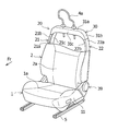
- FIG. 1 is a schematic perspective view showing a state in which a seat cushion cover or the like is installed in a vehicle seat back frame structure according to the present invention.
- FIG. 2 is a schematic perspective view showing a state in which a part of the vehicle seat back cover of FIG. 1 is cut away and an upper portion of the seat back frame is partially exposed.
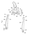
- FIG. 3 is an exploded perspective view showing a state before the first member and the second member constituting the left and right vertical frames and the upper cross member of the seat back frame of FIG. 2 are assembled.
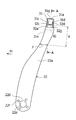
- FIG. 4 is a side view of a state in which the left vertical frame and the upper cross member in FIG. 3 are assembled, and the upper cross member shows a cross section.
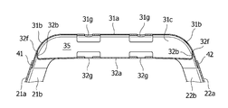
- FIG. 5 is a cross-sectional view taken along line AA in FIG. 4.
- the vehicle seat back frame structure according to the present embodiment will be described by taking, as an example, a seat back frame structure of a vehicle seat for one person such as a driver seat and a passenger seat as shown in FIG.
- the vehicle seat includes a seat cushion 1, a seat back 2, and a headrest 4.
- the seat cushion 1 As shown in FIGS. 1 and 2, the seat cushion 1 has a seat surface portion 1 a on which an occupant sits.
- the seat cushion 1 is configured to be slidable on a rail 5 installed on a vehicle body floor panel (not shown). A description of the sliding mechanism for sliding the seat cushion 1 is omitted.
- a seat cushion frame 11 constituting a skeleton of the seat cushion 1 is provided inside the seat cushion 1. Although detailed illustration is omitted, the seat cushion frame 11 is disposed inside the seat cushion 1 on both left and right sides of the seat surface portion 1a.
- the left and right here correspond to the left and right when the occupant seated in the vehicle seat looks at the front of the vehicle. Therefore, the seat cushion frame 11 virtually illustrated in FIG. 2 is the left seat cushion frame 11.
- the seat cushion frame 11 is a plate-like member that is formed of a carbon fiber reinforced resin material and extends in the vehicle front-rear direction while standing with respect to the vehicle body floor panel, as shown in FIG.
- the lower part of the seat cushion frame 11 is configured to be slidable on the rail 5.
- the seat back 2 is a member having a backrest 2 a that can support the upper limbs of an occupant.
- the seat back 2 is configured to be rotatable relative to the seat cushion 1 by a reclining mechanism 39.
- the headrest 4 is attached to the upper part of the seat back 2 in a detachable state.
- the seat back frame 20 includes a right vertical frame (side frame) 21 and a left vertical frame (side frame) 22 formed of a carbon fiber reinforced resin material.
- the right vertical frame 21 and the left vertical frame 22 are arranged on the left and right sides (both sides in the seat width direction) of the backrest portion 2a of the seat back 2, and are arranged in parallel so as to form a pair with a space between each other in the seat width direction. Has been.
- the right vertical frame 21 is a member that extends upward from the rear of the right seat cushion frame (not shown) and is rotatably attached to the right seat cushion frame via a reclining mechanism 39. 2 and 3, the right vertical frame 21 has a vertical wall portion 21a having a surface facing the vehicle width direction outer side and the inner side, and an edge of the vertical wall portion 21a projecting toward the center side in the seat width direction. Flange portions 21b and 21c, which are integrally formed.
- the rear flange portion 21c protruding from the rear end of the vertical wall portion 21a toward the center side in the sheet width direction is more than the front flange portion 21b protruding from the front end of the vertical wall portion 21a toward the center side in the sheet width direction.
- the overhanging length (length in the sheet width direction) is long.
- An inner opening is formed by these flange portions 21b and 21c so as to open in the sheet width direction.
- the vertical wall portion 21a, the front flange portion 21b, and the rear flange portion 21c form a U-shaped flat cross section (open cross-section structure) that opens to the center side (inner side) in the seat width direction.
- the installation part 21d for attaching the reclining mechanism 39 is provided in the lower part of the vertical wall part 21a.
- the installation portion 21d in this example has one large-diameter hole 21e and four small-diameter holes 21f arranged on the radially outer side of the large-diameter hole 21e.
- the small-diameter holes 21f are arranged at equal intervals around the large-diameter hole 21e.
- the reclining mechanism 39 is attached to these holes 21e and 21f by fastening members or the like.
- the main body is arranged on both outer sides in the seat width direction of the left and right vertical frames 21 and 22, and these are connected by pipes.
- the left vertical frame 22 is a member that extends upward from the rear portion of the left seat cushion frame 11 and is rotatably attached to the left seat cushion frame 11 via a reclining mechanism 39. ing. As shown in FIG. 3, the left vertical frame 22 has the vertical wall portion 22a, the front flange portion 22b, and the rear flange portion 22c, similarly to the right vertical frame 21. These are integrally formed to form a U-shaped flat cross section (open cross section structure) that opens to the center side (inner side) in the sheet width direction.
- the installation part 22d for attaching the reclining mechanism 39 is provided in the lower part of the vertical wall part 22a of the left side vertical frame 22 similarly to the vertical wall part 21a of the right side vertical frame 21. Similar to the right vertical frame 21, the installation portion 22d has one large-diameter hole 22e and four small-diameter holes 22f arranged on the radially outer side of the large-diameter hole 22e.
- the seat back frame 20 has an upper cross member 30 that connects the upper part of the right vertical frame 21 and the upper part of the left vertical frame 22.
- the configuration of the upper cross member 30 will be described.
- the upper cross member 30 is a member extending in the seat width direction, and has two members, that is, a first member 31 and a second member 32.
- the first member 31 has an upper surface portion 31a, a first front wall portion 31c, a first rear wall portion 31d, and side surface portions 31b on both sides in the seat width direction.
- the upper surface portion 31a is a portion extending in the sheet width direction, and a substantially flat surface is formed at the center portion of the upper surface portion 31a in the sheet width direction.
- the side surface portion 31b is a portion provided on both outer ends of the upper surface portion 31a in the sheet width direction.
- the side surface portion 31b is a curved inclined surface that inclines while curving downward in the vehicle as it goes from the outer end toward the outer side in the seat width direction.
- the center (not shown) of the curvature radius of the curve is disposed below the upper surface portion 31a.
- the first front wall portion 31c is a flat plate-like portion extending in the seat width direction while projecting from the front end of the upper surface portion 31a to the vehicle lower side, and a state projecting from the front end of the side surface portion 31b to the vehicle lower side. And a flat plate-like portion extending in the sheet width direction.
- 1st front wall part 31c located in the front end of side part 31b is curving below vehicles along the inclination of side part 31b.
- the lower end 31e of the first front wall portion 31c disposed at the front end of the side surface portion 31b is disposed below the vehicle from the lower end 31f of the first front wall portion 31c disposed at the front end of the upper surface portion 31a. That is, the ridgeline shape of the lower ends 31e and 31f of the first front wall portion 31c is formed to be a shallow U-shape that opens downward as viewed from the front of the seat.
- first rear wall portion 31d is not shown in FIG. 3 because it is a hidden portion in FIG. 3, the first rear wall portion 31d is projected downward from the rear end of the upper surface portion 31a and the rear end portion of the side surface portion 31b.
- 1 is a flat plate-like portion extending in the sheet width direction, like the front wall portion 31c.
- the first rear wall portion 31d is formed to have substantially the same shape as the first front wall portion 31c, and the side surface portion 31b is inclined at each of both end portions in the seat width direction of the first rear wall portion 31d. Along the vehicle is curved downward.
- the lower part of the first member 31 includes an opening (lower opening) that opens downward from the vehicle by a lower part of the first front wall part 31c, a lower part of the first rear wall part 31d, and lower parts of the side parts 31b on the left and right sides. Part).
- the first member 31 has a box shape that opens downward from the vehicle.
- the edge of the lower opening is constituted by the lower ends 31e and 31f of the first front wall 31c, the lower end of the first rear wall 31d, and the like, and on both sides in the sheet width direction, as it goes outward in the sheet width direction,
- the vehicle is inclined so as to bend downward.
- the first member 31 has a U-shaped cross section (open cross-section structure) that opens to the lower side of the vehicle by the upper surface portion 31a, the first front wall portion 31c, and the first rear wall portion 31d.
- the seat back frame 20 includes a right joint 41 and a lower portion of the left and right side surfaces 31b of the first member 31 and upper portions of the vertical walls 21a and 22a of the left and right vertical frames 21 and 22.
- a left joint 42 is provided. Details of the positions of the joint portions 41 and 42 will be described later.
- the first front wall portion 31 c adjacent to the side surface portion 31 is joined to the front flange portions 21 b and 22 b of the vertical frames 21 and 22, and the first rear wall portion 31 d adjacent to the side surface portion 31 is connected to the vertical frame 21, 22 is joined to the rear flange portions 21c and 22c. Details will be described later.
- the second member 32 has a lower surface portion 32a, a second front wall portion 32c, a second rear wall portion 32d, and side wall portions 32b on both sides in the seat width direction.
- the lower surface portion 32a is a plate-like portion extending in the sheet width direction, and has a substantially flat surface. In this example, although it extends substantially linearly, for example, the center portion in the sheet width direction may be curved so as to be positioned above both side portions in the sheet width direction.
- the second front wall portion 32c is a flat plate-like portion extending in the seat width direction in a state of projecting upward from the front end of the lower surface portion 32a.
- the second rear wall portion 32d is a flat plate-like portion extending in the seat width direction, like the second front wall portion 32c, in a state of projecting upward from the rear end of the lower surface portion 32a.
- the side wall portion 32 b protrudes upward from the outer end of the lower surface portion 32 a in the seat width direction.
- the vehicle vertical direction height with respect to the lower surface part 32a from which the side wall part 32b protrudes is configured to be lower than the vehicle vertical direction heights of the second front wall part 32c and the second rear wall part 32d.
- an upper opening that opens above the vehicle is configured by the upper part of the second front wall part 32c, the upper part of the second rear wall part 32d, and the upper part of each side wall part 32b. ing.
- the second member 32 has a box shape that is open above the vehicle.
- the second member 32 has a U-shaped cross section (open cross-sectional structure) that opens upward from the vehicle by the lower surface portion 32a, the second front wall portion 32c, and the second rear wall portion 32d.
- the second member 32 is joined in a state of being accommodated inside the lower opening of the first member 31.
- the front surface (outer surface) of the second front wall portion 32 c of the second member 32 is in contact with the rear surface (inner surface) of the first front wall portion 31 c of the first member 31.
- the rear surface (outer surface) of the second rear wall portion 32d of the second member 32 is adhered by an adhesive while being in contact with the front surface (inner surface) of the first rear wall portion 31d of the first member 31.
- the upper end of the side wall portion 32 b of the second member 32 is in contact with the lower surface side (back side) of the side surface portion 31 b of the first member 31.
- a hollow closed cross-section structure 35 is constituted by the first member 31 and the second member 32 as shown in FIGS. Is done.
- illustration of the 2nd front wall part 32c joined to the 1st front wall part 31c is abbreviate
- the upper cross member 30 and the like As described above, the upper cross member is suppressed while preventing separation of the joint at the joint portion of the hollow closed cross-section structure 35 provided in the upper cross member 30 constituting the seat back frame 20. It is possible to ensure the rigidity of 30.
- the upper cross member 30 that requires high bending rigidity and torsional rigidity has a hollow closed cross-section structure 35.
- the left and right vertical frames 21 and 22 having lower strength required than the upper cross member 30 have a U-shaped open cross-sectional structure that opens inward. Thereby, in the seat back frame 20, a lighter seat back frame structure can be obtained as compared with a case where all have a closed cross-sectional structure.
- the hollow closed cross-section structure 35 is formed by stacking two parts of the first member 31 and the second member 32 having a U-shaped open cross-section structure that opens upward or downward in the vehicle in the vertical direction of the vehicle and bonding them with an adhesive. Since it comprises, it is comprised so that a peeling load may not act only on the junction part joined by the adhesive agent. In this case, a peeling load and a compressive load act on the joint portion between the first member 31 and the second member 32. Therefore, it becomes possible to suppress the peeling load on the joint portion by the adhesive. As a result, breakage of the joint portion can be suppressed.
- the individual members such as the first member 31 and the second member 32 have a simple aperture shape, the difficulty in manufacturing is low. For this reason, in the construction method of the carbon fiber reinforced resin material, it is possible to manufacture using an RTM or press that is inexpensive and has a short tact time.
- the right joint 41 where the first member 31 and the right vertical frame 21 are joined will be described.
- the right side surface portion 31 b of the first member 31 in the seat width direction is joined to the vertical wall portion 21 a while being inserted inside the inner opening of the right vertical frame 21.
- the front surface (outer surface) of the first front wall portion 31c disposed at the front end of the right side surface portion 31b in the seat width direction is the front flange portion 21b of the right vertical frame 21. It is bonded with an adhesive in contact with the rear surface (inner surface).
- the rear surface (outer surface) of the first rear wall portion 31d disposed at the rear end of the right side surface portion 31b in the seat width direction is in contact with the front surface (inner surface) of the rear flange portion 21c of the right vertical frame 21. It is bonded with an adhesive while in contact.
- the left joint 42 where the first member 31 and the left vertical frame 22 are joined will be described.
- the left side surface portion 31 b of the first member 31 in the seat width direction is joined to the vertical wall portion 22 a in a state of being inserted inside the opening of the left vertical frame 22.
- the front surface (outer surface) of the first front wall portion 31 c arranged at the front end of the left side surface portion 31 b in the seat width direction is the rear surface (inner surface) of the front flange portion 22 b of the left vertical frame 22. It is bonded by an adhesive in a contact state.
- the rear surface (outer surface) of the first rear wall portion 31d disposed at the rear end of the left side surface portion 31b in the seat width direction is in contact with the front surface (inner surface) of the rear flange portion 22c of the left vertical frame 22. It is bonded with an adhesive while in contact.
- the left and right vertical frames 21 and 22 are arranged on the outer side in the seat width direction of the first member 31 of the upper cross member 30, for example, when a rear impact load is input to the upper cross member 30.
- the left and right vertical frames 21 and 22 can suppress deformation of the upper cross member 30 in the load direction.
- the part that receives the rear impact load is only the adhesive strength of the left and right joints 41 and 42 by the adhesive.
- strength with respect to a rear impact load improves.
- the application area of the adhesive is small, the amount of adhesive used can be suppressed, leading to cost reduction.
- the adhesive is mainly applied to the end portion of the member, workability is also good. Furthermore, the size of the fixing jig or the like can be reduced.
- the vehicle vertical direction positions of the left and right joint portions 41, 42 where the first member 31 and the left and right vertical frames 21, 22 are joined are the same as the first member 31.
- the joint portions 41 and 42 are arranged in a region in a range indicated by X in FIG. In FIG. 4, the position of the left joint 42 is shown, but the right joint 41 is the same.
- two upper through holes 31 g are formed in the upper surface portion 31 a of the first member 31. These through holes are arranged at intervals in the sheet width direction.
- two lower through holes 32g are formed in the lower surface portion 32a of the second member 32, and these lower through holes 32g are arranged at intervals in the sheet width direction.
- the right upper through hole 31g on the upper surface portion 31a and the right lower through hole 32g on the lower surface portion 32a communicate with each other in the vehicle vertical direction.
- the left upper through hole 31g in the upper surface portion 31a and the left lower through hole 32g in the lower surface portion 32a communicate with each other.
- the headrest frame 4a is inserted into the right side upper through hole 31g and the lower side through hole 32g communicating vertically and the left side upper hole 31g and the lower through hole 32g communicating vertically.
- These four through holes 31g and 32g can also be used as positioning holes when the upper cross member 30 is assembled. For example, the position adjustment when joining the first member 31 and the second member 32 is facilitated by inserting the round bar member into the through holes 31g and 32g communicating with each other in the vertical direction.
- the upper end 32h of the side wall portion 32b of the second member 32 is in contact with the back side of the side surface portion 31b of the first member 31.
- the present invention is not limited to this, and may be joined by an adhesive.
- the first front wall portion 31c and the second front wall portion 32c may be joined with the front and back reversed. That is, you may join the 2nd front wall part 32 to the front surface of the 1st front wall part 31c. The same applies to the first rear wall portion 31d and the second rear wall portion 32d.
- the joining of the upper cross member 30 and the left and right vertical frames 21 and 22 is not limited to joining by an adhesive.
- mechanical joining may be used.
- the vertical frames 21 and 22 are not limited to fiber reinforced resin materials, but may be metal materials, non-ferrous metal materials, or other resin materials.
Landscapes
- Engineering & Computer Science (AREA)
- Aviation & Aerospace Engineering (AREA)
- Transportation (AREA)
- Mechanical Engineering (AREA)
- Seats For Vehicles (AREA)
Abstract
アッパークロスメンバーの閉断面構造の接合部における接合の剥離を抑制しつつ、アッパークロスメンバーの剛性を確保する。車両用シートバックフレーム構造は、樹脂製のサイドフレーム(21,22)と、サイドフレーム(21,22)の上部に架け渡されたアッパークロスメンバー(30)を備える。アッパークロスメンバー(30)は、第1メンバー(31)と、第1メンバー(31)の下方に配置される第2メンバー(32)を有する。第1メンバー(31)の下部には開口部が設けられ、第1メンバー(31)は、下方に開口する横断面形状を有し、第2メンバー(32)の上部には開口部が設けられ、第2メンバー(32)は、上方に開口する横断面形状を有する。第1メンバー(31)の開口部と第2メンバー(32)の開口部が対向している状態で接合されることにより、閉断面構造が構成されている。
Description
本発明は、車両用シートバックフレーム構造に関する。
車両用シートは、乗員が着座するシートクッションと、乗員の上肢を支持するシートバックを備えている。シートバックを構成するフレームは、例えば、特許文献1に開示されているように、繊維強化複合材料等の樹脂材料により形成されているものが知られている。この例のシートバックフレームは、シートの強度及び剛性の向上、さらに軽量化を行うために、中空閉断面構造を有している。
中空閉断面構造を一体的に形成しようとすると、例えば2つの部材を接合することで中空閉断面構造を形成する場合に比べ、高コストとなる。そのため、通常は、一方が開いている断面形状を有する部材、例えばコ字状の開断面構造を有している2つの部材を組み合わせて接着剤等により接合することによって、中空閉断面構造が構成されている。
上記例のような構造では、シートバックフレームが全て閉断面構造となるため、高い剛性を求めていない小型車や軽自動車向けの鉄鋼製シートフレームよりも高剛性の構造となり、いわゆるオーバースペックとなる可能性がある。また、これに伴い、シート重量も重くなる可能性もある。
また、上記例では、シートバックフレームの上部のシート幅方向に延びる部分(アッパークロスメンバー)となる2つの部品が、シート前後方向に重ねた閉断面構造とし、接着剤で固定する構造となっているが、後突時に乗員が、当該アッパークロスメンバーへ衝突荷重が入力されたときに、アッパークロスメンバーの中央が、後方へ曲がるような変形となる。このような変形が起こると、接着剤による接合部に乖離方向の荷重が入力されることになる。
接着剤は、せん断荷重に対して乖離荷重には強度が低くなる可能性がある。このため、接着剤を用いた接合構造に対して、上記のような変形の発生は好ましくない。
また、シートバックフレームの上部には、ヘッドレストを支持する部分が設けられているが、当該部分は、複雑な形状であることが多い。そのため、繊維強化樹脂材料により成形する場合、成形の難易度が高くなり、生産性の低下を招く可能性がある。
さらに、アウターフレーム部材と、インナーフレーム部材を接着剤で接合しているため、接着剤の塗布面積が大きくなり、これに伴い、接着剤の塗布量も多くなる。また、塗布する位置が複雑なため、作業性悪化や接着剤の材料費が高額になる可能性がある。
本発明は上記課題を解決するためになされたものであって、その目的は、シートバックフレームを構成するアッパークロスメンバーに設けられた閉断面構造の接合部分における接合の剥離を抑制しつつ、アッパークロスメンバーの剛性を確保できる車両用シートバックフレーム構造を提供することである。
上記目的を達成するため本発明に係る車両用シートバックフレーム構造は、車両上下方向に延び、シート幅方向に間隔を空けて配置されている樹脂製の2つのサイドフレームと、シート幅方向に延び、前記各サイドフレームの上部を連結しているアッパークロスメンバーと、を備えている。当該車両用シートバックフレーム構造において、前記アッパークロスメンバーは、シート幅方向に延びている第1メンバーと、該第1メンバーの下方に配置され、シート幅方向に延びている第2メンバーとを有しており、前記第1メンバーの下部には、シート幅方向に延び、車両下方に開口する下方開口部が設けられ、前記第2メンバーの上部には、シート幅方向に延び、車両上方に開口する上方開口部が設けられ、前記アッパークロスメンバーには、前記第1メンバーの前記下方開口部と前記第2メンバーの前記上方開口部により、閉断面構造が構成されている。
本発明によれば、シートバックフレームを構成するアッパークロスメンバーに設けられた閉断面構造の接合部分における接合の剥離を抑制しつつ、アッパークロスメンバーの剛性を確保することが可能となる。
以下、本発明に係る車両用シートバックフレーム構造の実施形態について、図面(図1~図5)を参照して説明する。
本実施形態に係る車両用シートバックフレーム構造は、図1に示すように、例えば、運転席や助手席等の一人掛け用の車両用シートのシートバックフレーム構造を例に挙げて説明する。当該車両用シートは、シートクッション1と、シートバック2と、ヘッドレスト4を備えている。
先ず、シートクッション1について説明する。シートクッション1は、図1及び図2に示すように、乗員が着座する座面部1aを有している。シートクッション1は、図示しない車体フロアパネル上に設置されているレール5の上をスライド可能に構成されている。シートクッション1をスライドさせるためのスライド機構についての説明は省略する。
シートクッション1の内部には、シートクッション1の骨格を構成するシートクッションフレーム11が設けられている。詳細な図示は省略しているが、シートクッションフレーム11は、シートクッション1の内部において、座面部1aの左右の両側部に配置されている。
なお、ここでの左右は、車両用シートに着座した乗員が車両前方を見ているときの左右に対応している。よって、図2に仮想的に示されているシートクッションフレーム11は、左側のシートクッションフレーム11である。
シートクッションフレーム11は、炭素繊維強化樹脂材料により形成され、図2に示すように、車体フロアパネルに対して起立している状態で、車両前後方向に延びている板状の部材である。シートクッションフレーム11の下部は、レール5上をスライド可能に構成されている。
次に、シートバック2について説明する。シートバック2は、図1及び図2に示すように、乗員の上肢を支持可能な背もたれ部2aを有する部材である。当該シートバック2は、リクライニング機構39によって、シートクッション1に対して、相対回転可能に構成されている。また、シートバック2の上部には、ヘッドレスト4が着脱可能な状態で取り付けられている。
シートバック2の内部には、図2に示すように、シートバック2の骨格を構成するシートバックフレーム20が設けられている。以下、シートバックフレーム20について説明する。シートバックフレーム20は、炭素繊維強化樹脂材料により形成された右側縦フレーム(サイドフレーム)21と左側縦フレーム(サイドフレーム)22を有している。
右側縦フレーム21と左側縦フレーム22は、シートバック2の背もたれ部2aの左右(シート幅方向両側部)に配置されており、シート幅方向に互いに間隔空けて、対をなすように平行に配置されている。
右側縦フレーム21は、図示しない右側のシートクッションフレームの後部から車両上方に延びている部材であり、リクライニング機構39を介して右側のシートクッションフレームに回転可能に取り付けられている。当該右側縦フレーム21は、図2及び図3に示すように、車幅方向外側及び内側に臨む面を有する縦壁部21aと、該縦壁部21aの縁端からシート幅方向中央側に張り出しているフランジ部21b,21cとを有し、これらが一体的に形成されている。
該縦壁部21aの後端から、シート幅方向中央側に張り出している後側フランジ部21cは、該縦壁部21aの前端から、シート幅方向中央側に張り出している前側フランジ部21bよりも、張り出している長さ(シート幅方向長さ)が長い。これらのフランジ部21b,21cによりシート幅方向に開口するように内側開口部が構成されている。この例では、縦壁部21aと、前側フランジ部21b及び後側フランジ部21cにより、シート幅方向中央側(内側)に開くコ字状の平断面(開断面構造)が構成されている。
縦壁部21aの下部には、リクライニング機構39を取り付けるための設置部21dが設けられている。この例の設置部21dは、1つの径大孔21eと、該径大孔21eの径方向外側に配置されている4つの径小孔21fを有している。径小孔21fは、径大孔21eの周囲を等間隔に配置されている。リクライニング機構39は、これらの孔21e,21fに、締結部材等により取り付けられている。当該リクライニング機構39の詳細な説明は省略しているが、左右の縦フレーム21,22のシート幅方向の両外側に本体が配置され、これらをパイプで連結することにより構成されている。
続いて、左側縦フレーム22について説明する。左側縦フレーム22は、図2に示すように、左側のシートクッションフレーム11の後部から車両上方に延びている部材であり、リクライニング機構39を介して左側のシートクッションフレーム11に回転可能に取り付けられている。当該左側縦フレーム22は、図3に示すように、右側縦フレーム21と同様に、該縦壁部22a、前側フランジ部22b及び後側フランジ部22cを有している。これらが一体的に形成され、シート幅方向中央側(内側)に開くコ字状の平断面(開断面構造)が構成されている。
左側縦フレーム22の縦壁部22aの下部には、右側縦フレーム21の縦壁部21aと同様に、リクライニング機構39を取り付けるための設置部22dが設けられている。当該設置部22dは、右側縦フレーム21と同様に、1つの径大孔22eと、該径大孔22eの径方向外側に配置されている4つの径小孔22fを有している。
さらに、シートバックフレーム20は、図3に示すように、右側縦フレーム21の上部と左側縦フレーム22の上部とを連結しているアッパークロスメンバー30を有している。以下、アッパークロスメンバー30の構成について説明する。
アッパークロスメンバー30は、シート幅方向に延びている部材で、2つのメンバー、すなわち、第1メンバー31及び第2メンバー32を有している。
第1メンバー31は、図3及び図4に示すように、上面部31aと、第1前壁部31cと、第1後壁部31dと、シート幅方向両側部の側面部31bを有している。上面部31aは、シート幅方向に延びている部分であり、上面部31aのシート幅方向における中央部は、略平坦な面が形成されている。
側面部31bは、上面部31aのシート幅方向の両外側端に設けられている部分である。側面部31bは、当該外側端からシート幅方向外側に向かうに従い、車両下方に湾曲しながら傾斜する湾曲傾斜面となっている。湾曲の曲率半径の中心(図示せず)は、上面部31aよりも車両下方に配置されている。
第1前壁部31cは、上面部31aの前端から車両下方に張り出している状態でシート幅方向に延びている平坦な板状の部分と、側面部31bの前端から車両下方に張り出している状態でシート幅方向に延びている平坦な板状の部分とにより構成されている。
側面部31bの前端に位置する第1前壁部31cは、側面部31bの傾斜に沿って車両下方に湾曲している。側面部31bの前端に配置された第1前壁部31cの下端31eは、上面部31aの前端に配置された第1前壁部31cの下端31fよりも、車両下方に配置されている。すなわち、第1前壁部31cの下端31e,31fの稜線形状は、シート前方視で、下方に開く浅いU字状となるように形成されている。
第1後壁部31dは、図3では隠れる部分となるため図示は省略しているが、上面部31aの後端及び側面部31bの後端のそれぞれから車両下方に張り出している状態で、第1前壁部31cと同様に、シート幅方向に延びている平坦な板状の部分である。第1後壁部31dは、第1前壁部31cとほぼ同形状となるように形成されており、第1後壁部31dのシート幅方向の両端部のそれぞれにおいては、側面部31bの傾斜に沿って、車両下方に湾曲している。
当該第1メンバー31の下部には、第1前壁部31cの下部と、第1後壁部31dの下部と、左右両側の側面部31bの下部により、車両下方に開口する開口部(下方開口部)が構成されている。第1メンバー31は、車両下方に開口している箱型形状である。
当該下方開口部の縁部は、第1前壁部31cの下端31e,31fや第1後壁部31dの下端等により構成され、シート幅方向の両側部において、シート幅方向外側に向かうに従い、車両下方に湾曲するように傾斜している。また、第1メンバー31には、上面部31aと、第1前壁部31c及び第1後壁部31dにより、車両下方に開くコ字状の横断面(開断面構造)が構成されている。
また、シートバックフレーム20には、第1メンバー31の左右の側面部31bにおける下部と、左右の縦フレーム21,22の縦壁部21a,22aの上部とが接合される右側の接合部41及び左側の接合部42が設けられている。当該接合部41,42の位置の詳細は、後で説明する。また、側面部31に隣接する第1前壁部31cは、縦フレーム21,22の前側フランジ部21b,22bに接合され、側面部31に隣接する第1後壁部31dは、縦フレーム21,22の後側フランジ部21c,22cに接合されている。詳細は後で説明する。
第2メンバー32は、図3に示すように、下面部32aと、第2前壁部32cと、第2後壁部32dと、シート幅方向の両側部の側壁部32bを有している。下面部32aは、シート幅方向に延びている板状の部分で、略平坦な面が形成されている。この例では、ほぼ直線的に延びているが、例えば、シート幅方向における中央部が、シート幅方向両側部よりも上方に位置するように湾曲してもよい。
第2前壁部32cは、下面部32aの前端から車両上方に張り出している状態で、シート幅方向に延びている平坦な板状の部分である。第2後壁部32dは、下面部32aの後端から車両上方に張り出している状態で、第2前壁部32cと同様に、シート幅方向に延びている平坦な板状の部分である。
側壁部32bは、図3に示すように、下面部32aのシート幅方向外側端から車両上方に突出している。側壁部32bが突出している下面部32aを基準とする車両上下方向高さは、第2前壁部32c及び第2後壁部32dの車両上下方向高さよりも低くなるように構成されている。
当該第2メンバー32の上部には、第2前壁部32cの上部と、第2後壁部32dの上部と、それぞれの側壁部32bの上部により、車両上方に開口する上方開口部が構成されている。当該第2メンバー32は、車両上方に開口している箱型形状である。また、第2メンバー32には、下面部32aと、第2前壁部32c及び第2後壁部32dにより、車両上方に開くコ字状の横断面(開断面構造)が構成されている。
続いて、第1メンバー31と第2メンバー32の接合について説明する。第2メンバー32は、第1メンバー31の下方開口部の内側に収容されている状態で接合されている。
図4に示すように、第2メンバー32の第2前壁部32cの前面(外面)は、第1メンバー31の第1前壁部31cの後面(内面)に当接している状態で接着剤により接着(接合)されている。同様に、第2メンバー32の第2後壁部32dの後面(外面)は、第1メンバー31の第1後壁部31dの前面(内面)に当接している状態で接着剤により接着されている。
さらに、図5に示すように、第2メンバー32の側壁部32bの上端は、第1メンバー31の側面部31bの下面側(裏側)に当接している。上記のように第1メンバー31と第2メンバー32を接着剤により接合することにより、図4及び図5に示すように、第1メンバー31と第2メンバー32により、中空閉断面構造35が構成される。なお、図5では、第1前壁部31cに接合される第2前壁部32cの図示は省略している。
上記のようにアッパークロスメンバー30等を構成することにより、シートバックフレーム20を構成するアッパークロスメンバー30に設けられた中空閉断面構造35の接合部分における接合の剥離を抑制しつつ、アッパークロスメンバー30の剛性を確保することが可能となる。
高い曲げ剛性、ねじり剛性が求められるアッパークロスメンバー30は、中空閉断面構造35を有している。これに対して、アッパークロスメンバー30よりも要求される強度が低い左右の縦フレーム21,22は、内側に開くコ字状の開断面構造としている。これにより、シートバックフレーム20において、全て閉断面構造とする場合に比べて、より軽量なシートバックフレーム構造を得ることができる。
また、炭素繊維強化樹脂材料は、鋼材と比較して、高額な材料であるため、シートバックフレーム構造において、中空閉断面構造と、開断面構造を、必要に応じて使い分けていることで、炭素繊維強化樹脂材料の使用量を抑制することができる。その結果、材料費を削減することが可能となる。
また、車両上方または下方に開くコ字状の開断面構造の第1メンバー31と第2メンバー32の2部品を、車両上下方向に重ね、接着剤により接合することによって、中空閉断面構造35を構成しているため、接着剤により接合されている接合部分にのみ剥離荷重が作用しないように構成されている。この場合、第1メンバー31と第2メンバー32の接合部分には、剥離荷重と圧縮荷重が作用する。そのため、接着剤による接合部分への剥離荷重を抑制することが可能となる。その結果、接合部分の破断を抑制できる。
また、第1メンバー31や第2メンバー32等の個々のメンバーは、単純な絞り形状であるため、製造上の難易度は低い。このため、炭素繊維強化樹脂材料の工法の中では、安価でタクトタイムが短いRTMやプレスを用いた製作が可能となる。
続いて、第1メンバー31と、右側縦フレーム21とが接合される右側の接合部41について説明する。第1メンバー31のシート幅方向の右側の側面部31bは、右側縦フレーム21の内側開口部の内側に挿入されている状態で、縦壁部21aに接合されている。
上述したように、第1メンバー31において、シート幅方向の右側の側面部31bの前端に配置されている第1前壁部31cの前面(外面)は、右側縦フレーム21の前側フランジ部21bの後面(内面)に当接している状態で接着剤により接着されている。同様に、シート幅方向の右側の側面部31bの後端に配置されている第1後壁部31dの後面(外面)は、右側縦フレーム21の後側フランジ部21cの前面(内面)に当接している状態で接着剤により接着されている。
続いて、第1メンバー31と、左側縦フレーム22とが接合される左側の接合部42について説明する。第1メンバー31のシート幅方向の左側の側面部31bは、左側縦フレーム22の開口部の内側に挿入されている状態で、縦壁部22aに接合されている。
第1メンバー31において、シート幅方向の左側の側面部31bの前端に配置されている第1前壁部31cの前面(外面)は、左側縦フレーム22の前側フランジ部22bの後面(内面)に当接している状態で接着剤により接着されている。同様に、シート幅方向の左側の側面部31bの後端に配置されている第1後壁部31dの後面(外面)は、左側縦フレーム22の後側フランジ部22cの前面(内面)に当接している状態で接着剤により接着されている。
上記のように、アッパークロスメンバー30の第1メンバー31のシート幅方向外側に、左右の縦フレーム21,22を配置することで、例えば、後突荷重が、アッパークロスメンバー30に入力されたときに、左右の縦フレーム21,22は、荷重方向にアッパークロスメンバー30の変形を抑制することができる。その結果、接着剤による接合部41,42で後突荷重を受け、さらに、構造上、縦フレーム21,22でも当該後突荷重を受けることができる。
仮に、アッパークロスメンバー30の内側に左右の縦フレーム21,22を配置すると、後突荷重を受ける部分が、接着剤による左右の接合部41,42の接着強度のみとなる。これに対して、上記のように構成しているので、後突荷重に対する強度が向上する。
さらに、上記の構成では、接着剤の塗布面積が小さいため、接着剤の使用量が抑制でき、コスト低減につながる。また、主としてメンバーの端部に接着剤を塗布しているため、作業性も良好である。さらに、固定用治具等のサイズを小さくすることも可能である。
また、本実施形態では、図4に示すように、第1メンバー31と左右の縦フレーム21,22とが接合される左右の接合部41,42の車両上下方向位置は、第1メンバー31と第2メンバー32で構成される中空閉断面構造35の車両上下方向位置よりも車両下方で、左右の縦フレーム21,22におけるシート前後方向幅が最小となる車両上下方向位置Pよりも車両上方に配置されている。すなわち、図4のXで示されている範囲の領域に接合部41,42を配置している。なお、図4では、左側の接合部42の位置を示しているが、右側の接合部41も同様である。
このように、左右の接合部41,42を応力集中部位から離すことで、衝突荷重や疲労による破断を抑制することができる。
ここで、ヘッドレストフレーム4aが、アッパークロスメンバー30に取り付けられている状態について説明する。図5に示すように、第1メンバー31の上面部31aには、2つの上側貫通孔31gが形成されている。これらの貫通孔は、シート幅方向に間隔を空けて配置されている。同様に、第2メンバー32の下面部32aにも、2つの下側貫通孔32gが形成され、これらの下側貫通孔32gは、シート幅方向に間隔を空けて配置されている。
上面部31aにおける右側の上側貫通孔31gと、下面部32aにおける右側の下側貫通孔32gは、第1メンバー31と第2メンバー32が組み立てられているときに、車両上下方向に連通する。同様に、上面部31aにおける左側の上側貫通孔31gと、下面部32aにおける左側の下側貫通孔32gも、連通している。
上下に連通する右側の上側貫通孔31g及び下側貫通孔32gと、上下に連通する左側の上側貫通孔31g及び下側貫通孔32gには、ヘッドレストフレーム4aが挿入される。これらの4つの貫通孔31g,32gは、アッパークロスメンバー30を組み立てる時ときに、位置決め用の孔としても用いることが可能である。例えば、丸棒部材を、上下に連通する貫通孔31g,32gに挿入することで、第1メンバー31と第2メンバー32を接合するときの位置調整が容易になる。
本実施形態の説明は、本発明を説明するための例示であって、特許請求の範囲に記載の発明を限定するものではない。また、本発明の各部構成は上記実施形態に限らず、特許請求の範囲に記載の技術的範囲内で種々の変形が可能である。
上記実施形態では、第1メンバー31と第2メンバー32で構成される中空閉断面構造35において、第2メンバー32の側壁部32bの上端32hは、第1メンバー31の側面部31bの裏側に当接させているが、これに限らず、接着剤により接合してもよい。また、第1前壁部31cと第2前壁部32cとを、前後を逆にして接合してもよい。すなわち、第1前壁部31cの前面に、第2前壁部32を接合してもよい。第1後壁部31dと第2後壁部32dについても同様である。
また、アッパークロスメンバー30と、左右の縦フレーム21,22の接合は、接着剤による接合に限られない。例えば、機械的な接合(リベット接合やカシメ接合)でもよい。また、縦フレーム21,22は、繊維強化樹脂材料に限らず、金属材料、非鉄金属材料、やその他の樹脂材料でもよい。
1 シートクッション
1a 座面部
2 シートバック
2a 背もたれ部
4 ヘッドレスト
4a ヘッドレストフレーム
5 レール
11 シートクッションフレーム
21 右側縦フレーム(サイドフレーム)
21a 縦壁部
21b 前側フランジ部
21c 後側フランジ部
21d 設置部
21e 径大孔
21f 径小孔
22 左側縦フレーム(サイドフレーム)
22a 縦壁部
22b 前側フランジ部
22c 後側フランジ部
22d 設置部
22e 径大孔
22f 径小孔
30 アッパークロスメンバー
31 第1メンバー
31a 上面部
31b 側面部
31c 第1前壁部
31d 第1後壁部
31g 上側貫通孔
32 第2メンバー
32a 下面部
32b 側壁部
32c 第2前壁部
32d 第2後壁部
32g 下側貫通孔
39 リクライニング機構
41 右側の接合部
42 左側の接合部
Claims (3)
- 車両上下方向に延び、シート幅方向に間隔を空けて配置されている樹脂製の2つのサイドフレームと、シート幅方向に延び、前記各サイドフレームの上部を連結しているアッパークロスメンバーと、を備えている車両用シートバックフレーム構造において、
前記アッパークロスメンバーは、シート幅方向に延びている第1メンバーと、該第1メンバーの下方に配置され、シート幅方向に延びている第2メンバーとを有しており、
前記第1メンバーの下部には、シート幅方向に延び、車両下方に開口する下方開口部が設けられ、前記第2メンバーの上部には、シート幅方向に延び、車両上方に開口する上方開口部が設けられ、
前記アッパークロスメンバーには、前記第1メンバーの前記下方開口部と前記第2メンバーの前記上方開口部により、閉断面構造が構成されていることを特徴とする車両用シートバックフレーム構造。 - 前記サイドフレームのシート幅方向の内側には、車両上下方向に延び、シート幅方向の内側に開口する内側開口部が設けられ、
前記第2メンバーは、前記第1メンバーの前記下方開口部の内側に収容されている状態で接合され、
前記第1メンバーのシート幅方向端部は、前記サイドフレームの前記内側開口部の内側に挿入されている状態で接合されていることを特徴とする請求項1に記載の車両用シートバックフレーム構造。 - 前記アッパークロスメンバーと前記サイドフレームとが接合される接合部の車両上下方向位置は、前記アッパークロスメンバーの前記閉断面構造の車両上下方向位置よりも車両下方で、前記サイドフレームの前後方向幅が最小となる車両上下方向位置よりも車両上方に配置されていることを特徴とする請求項1または請求項2に記載の車両用シートバックフレーム構造。
Priority Applications (2)
| Application Number | Priority Date | Filing Date | Title |
|---|---|---|---|
| CN201880006379.3A CN110167794B (zh) | 2017-01-24 | 2018-01-22 | 车辆用座椅靠背框架构造 |
| EP18745414.5A EP3575145B1 (en) | 2017-01-24 | 2018-01-22 | Vehicular seat back frame structure |
Applications Claiming Priority (2)
| Application Number | Priority Date | Filing Date | Title |
|---|---|---|---|
| JP2017010472A JP6760857B2 (ja) | 2017-01-24 | 2017-01-24 | 車両用シートバックフレーム構造 |
| JP2017-010472 | 2017-01-24 |
Publications (1)
| Publication Number | Publication Date |
|---|---|
| WO2018139385A1 true WO2018139385A1 (ja) | 2018-08-02 |
Family
ID=62978429
Family Applications (1)
| Application Number | Title | Priority Date | Filing Date |
|---|---|---|---|
| PCT/JP2018/001704 WO2018139385A1 (ja) | 2017-01-24 | 2018-01-22 | 車両用シートバックフレーム構造 |
Country Status (4)
| Country | Link |
|---|---|
| EP (1) | EP3575145B1 (ja) |
| JP (1) | JP6760857B2 (ja) |
| CN (1) | CN110167794B (ja) |
| WO (1) | WO2018139385A1 (ja) |
Cited By (1)
| Publication number | Priority date | Publication date | Assignee | Title |
|---|---|---|---|---|
| CN110576777A (zh) * | 2018-06-07 | 2019-12-17 | 株式会社塔捷斯 | 车辆用座椅 |
Citations (5)
| Publication number | Priority date | Publication date | Assignee | Title |
|---|---|---|---|---|
| JP2004016710A (ja) * | 2002-06-20 | 2004-01-22 | Shigeru Co Ltd | 車両用シートバック |
| JP2010046162A (ja) * | 2008-08-20 | 2010-03-04 | Nhk Spring Co Ltd | 車両用シートバックのフレーム構造及び該構造を有する車両用シートバック |
| WO2013021484A1 (ja) * | 2011-08-10 | 2013-02-14 | ジョンソン コントロールズ テクノロジー カンパニ- | 自動車用シートバックフレーム |
| JP2014065341A (ja) | 2012-09-24 | 2014-04-17 | Ts Tech Co Ltd | シートのフレーム |
| JP2016150658A (ja) * | 2015-02-17 | 2016-08-22 | テイ・エス テック株式会社 | シートフレーム及び車両用シート |
Family Cites Families (6)
| Publication number | Priority date | Publication date | Assignee | Title |
|---|---|---|---|---|
| FR2594760B1 (fr) * | 1986-02-21 | 1989-11-10 | Renault | Armature de siege a modules de construction assembles |
| JPH08214987A (ja) * | 1995-02-13 | 1996-08-27 | Ikeda Bussan Co Ltd | 座席のフレーム構造 |
| BRPI0408989B1 (pt) * | 2003-03-31 | 2015-07-07 | Ts Tech Co Ltd | Estrutura de encosto de assento para assento de veículo |
| JP2008067722A (ja) * | 2003-03-31 | 2008-03-27 | T S Tec Kk | 超高張力鋼板製自動車用シートバックフレーム |
| DE202006006834U1 (de) * | 2006-04-28 | 2006-07-27 | Faurecia Autositze Gmbh & Co. Kg | Rückenlehnenrahmen eines Kraftfahrzeugsitzes |
| EP2366584B1 (en) * | 2010-03-19 | 2012-08-22 | Petra Italia S.A.S. Di Marina Bordo & C. | A vehicle seat |
-
2017
- 2017-01-24 JP JP2017010472A patent/JP6760857B2/ja active Active
-
2018
- 2018-01-22 CN CN201880006379.3A patent/CN110167794B/zh active Active
- 2018-01-22 EP EP18745414.5A patent/EP3575145B1/en active Active
- 2018-01-22 WO PCT/JP2018/001704 patent/WO2018139385A1/ja unknown
Patent Citations (5)
| Publication number | Priority date | Publication date | Assignee | Title |
|---|---|---|---|---|
| JP2004016710A (ja) * | 2002-06-20 | 2004-01-22 | Shigeru Co Ltd | 車両用シートバック |
| JP2010046162A (ja) * | 2008-08-20 | 2010-03-04 | Nhk Spring Co Ltd | 車両用シートバックのフレーム構造及び該構造を有する車両用シートバック |
| WO2013021484A1 (ja) * | 2011-08-10 | 2013-02-14 | ジョンソン コントロールズ テクノロジー カンパニ- | 自動車用シートバックフレーム |
| JP2014065341A (ja) | 2012-09-24 | 2014-04-17 | Ts Tech Co Ltd | シートのフレーム |
| JP2016150658A (ja) * | 2015-02-17 | 2016-08-22 | テイ・エス テック株式会社 | シートフレーム及び車両用シート |
Cited By (1)
| Publication number | Priority date | Publication date | Assignee | Title |
|---|---|---|---|---|
| CN110576777A (zh) * | 2018-06-07 | 2019-12-17 | 株式会社塔捷斯 | 车辆用座椅 |
Also Published As
| Publication number | Publication date |
|---|---|
| EP3575145A4 (en) | 2020-01-01 |
| EP3575145B1 (en) | 2021-03-24 |
| CN110167794A (zh) | 2019-08-23 |
| CN110167794B (zh) | 2021-07-06 |
| EP3575145A1 (en) | 2019-12-04 |
| JP6760857B2 (ja) | 2020-09-23 |
| JP2018118585A (ja) | 2018-08-02 |
Similar Documents
| Publication | Publication Date | Title |
|---|---|---|
| EP3434566B1 (en) | Vehicle body lower structure | |
| JP6881326B2 (ja) | 下部車体構造 | |
| JP4825640B2 (ja) | 自動車の車体構造 | |
| US8152223B2 (en) | Sidewall for a motor vehicle | |
| US20170305469A1 (en) | Body structure of vehicle | |
| US20080277993A1 (en) | Metal Structure and Vehicle Seat | |
| JP5182478B2 (ja) | 車体の側突荷重支持構造および側突荷重支持方法 | |
| JP6664281B2 (ja) | 自動車のフロントピラー構造 | |
| JP2012017051A (ja) | 車両用シートフレームの支持構造 | |
| JP2018100048A (ja) | 乗物用シート | |
| JP2010254089A (ja) | 車両用シートの取付構造 | |
| EP3575143B1 (en) | Vehicular seat structure | |
| WO2018139385A1 (ja) | 車両用シートバックフレーム構造 | |
| JP2015174607A (ja) | 自動車の車体構造 | |
| JP6521660B2 (ja) | シートフレーム及び車両用シート | |
| JP2008302911A (ja) | 車体構造 | |
| JP5813088B2 (ja) | 車体構造 | |
| JP6973291B2 (ja) | 乗物用シート | |
| JP5776528B2 (ja) | 車体のフロア構造 | |
| JP2017056842A (ja) | 車両用座席固定構造 | |
| JP7406440B2 (ja) | 車両用シート | |
| KR102026813B1 (ko) | 자동차용 필러트림과 플로어 접합부의 보강구조 | |
| JP2008068737A (ja) | 車両の下部車体構造 | |
| JP2010018083A (ja) | 車体前部構造 | |
| JP2013244867A (ja) | シートバックフレーム |
Legal Events
| Date | Code | Title | Description |
|---|---|---|---|
| 121 | Ep: the epo has been informed by wipo that ep was designated in this application |
Ref document number: 18745414 Country of ref document: EP Kind code of ref document: A1 |
|
| NENP | Non-entry into the national phase |
Ref country code: DE |
|
| ENP | Entry into the national phase |
Ref document number: 2018745414 Country of ref document: EP Effective date: 20190826 |