WO2018122948A1 - Dispositif de chauffage par rayonnement infrarouge - Google Patents
Dispositif de chauffage par rayonnement infrarouge Download PDFInfo
- Publication number
- WO2018122948A1 WO2018122948A1 PCT/JP2016/088844 JP2016088844W WO2018122948A1 WO 2018122948 A1 WO2018122948 A1 WO 2018122948A1 JP 2016088844 W JP2016088844 W JP 2016088844W WO 2018122948 A1 WO2018122948 A1 WO 2018122948A1
- Authority
- WO
- WIPO (PCT)
- Prior art keywords
- infrared radiation
- air
- radiation heater
- combustion
- cylindrical body
- Prior art date
Links
- 230000005855 radiation Effects 0.000 claims abstract description 86
- 238000002485 combustion reaction Methods 0.000 claims abstract description 73
- 239000000446 fuel Substances 0.000 claims abstract description 39
- 239000000203 mixture Substances 0.000 claims abstract description 26
- 239000000463 material Substances 0.000 claims description 10
- 239000007789 gas Substances 0.000 description 14
- ATUOYWHBWRKTHZ-UHFFFAOYSA-N Propane Chemical compound CCC ATUOYWHBWRKTHZ-UHFFFAOYSA-N 0.000 description 8
- 239000002184 metal Substances 0.000 description 5
- 239000001294 propane Substances 0.000 description 4
- 229910000831 Steel Inorganic materials 0.000 description 2
- 238000010586 diagram Methods 0.000 description 2
- 239000000428 dust Substances 0.000 description 2
- 239000011810 insulating material Substances 0.000 description 2
- 239000003350 kerosene Substances 0.000 description 2
- VNWKTOKETHGBQD-UHFFFAOYSA-N methane Chemical compound C VNWKTOKETHGBQD-UHFFFAOYSA-N 0.000 description 2
- 239000010959 steel Substances 0.000 description 2
- PNEYBMLMFCGWSK-UHFFFAOYSA-N aluminium oxide Inorganic materials [O-2].[O-2].[O-2].[Al+3].[Al+3] PNEYBMLMFCGWSK-UHFFFAOYSA-N 0.000 description 1
- 239000000919 ceramic Substances 0.000 description 1
- 230000006866 deterioration Effects 0.000 description 1
- 230000000694 effects Effects 0.000 description 1
- 230000005611 electricity Effects 0.000 description 1
- 239000000835 fiber Substances 0.000 description 1
- -1 for example Substances 0.000 description 1
- 238000010438 heat treatment Methods 0.000 description 1
- 238000009413 insulation Methods 0.000 description 1
- 238000000034 method Methods 0.000 description 1
- 239000011490 mineral wool Substances 0.000 description 1
- 239000003345 natural gas Substances 0.000 description 1
- 239000011148 porous material Substances 0.000 description 1
- 230000002265 prevention Effects 0.000 description 1
- 229910001220 stainless steel Inorganic materials 0.000 description 1
- 239000010935 stainless steel Substances 0.000 description 1
Images


Classifications
-
- F—MECHANICAL ENGINEERING; LIGHTING; HEATING; WEAPONS; BLASTING
- F23—COMBUSTION APPARATUS; COMBUSTION PROCESSES
- F23D—BURNERS
- F23D14/00—Burners for combustion of a gas, e.g. of a gas stored under pressure as a liquid
- F23D14/12—Radiant burners
- F23D14/14—Radiant burners using screens or perforated plates
- F23D14/145—Radiant burners using screens or perforated plates combustion being stabilised at a screen or a perforated plate
-
- F—MECHANICAL ENGINEERING; LIGHTING; HEATING; WEAPONS; BLASTING
- F23—COMBUSTION APPARATUS; COMBUSTION PROCESSES
- F23C—METHODS OR APPARATUS FOR COMBUSTION USING FLUID FUEL OR SOLID FUEL SUSPENDED IN A CARRIER GAS OR AIR
- F23C3/00—Combustion apparatus characterised by the shape of the combustion chamber
- F23C3/002—Combustion apparatus characterised by the shape of the combustion chamber the chamber having an elongated tubular form, e.g. for a radiant tube
-
- F—MECHANICAL ENGINEERING; LIGHTING; HEATING; WEAPONS; BLASTING
- F23—COMBUSTION APPARATUS; COMBUSTION PROCESSES
- F23D—BURNERS
- F23D14/00—Burners for combustion of a gas, e.g. of a gas stored under pressure as a liquid
- F23D14/46—Details, e.g. noise reduction means
- F23D14/62—Mixing devices; Mixing tubes
-
- F—MECHANICAL ENGINEERING; LIGHTING; HEATING; WEAPONS; BLASTING
- F24—HEATING; RANGES; VENTILATING
- F24C—DOMESTIC STOVES OR RANGES ; DETAILS OF DOMESTIC STOVES OR RANGES, OF GENERAL APPLICATION
- F24C1/00—Stoves or ranges in which the fuel or energy supply is not restricted to solid fuel or to a type covered by a single one of the following groups F24C3/00 - F24C9/00; Stoves or ranges in which the type of fuel or energy supply is not specified
- F24C1/08—Stoves or ranges in which the fuel or energy supply is not restricted to solid fuel or to a type covered by a single one of the following groups F24C3/00 - F24C9/00; Stoves or ranges in which the type of fuel or energy supply is not specified solely adapted for radiation heating
- F24C1/10—Stoves or ranges in which the fuel or energy supply is not restricted to solid fuel or to a type covered by a single one of the following groups F24C3/00 - F24C9/00; Stoves or ranges in which the type of fuel or energy supply is not specified solely adapted for radiation heating with reflectors
- F24C1/12—Stoves or ranges in which the fuel or energy supply is not restricted to solid fuel or to a type covered by a single one of the following groups F24C3/00 - F24C9/00; Stoves or ranges in which the type of fuel or energy supply is not specified solely adapted for radiation heating with reflectors of circular shape
-
- F—MECHANICAL ENGINEERING; LIGHTING; HEATING; WEAPONS; BLASTING
- F24—HEATING; RANGES; VENTILATING
- F24C—DOMESTIC STOVES OR RANGES ; DETAILS OF DOMESTIC STOVES OR RANGES, OF GENERAL APPLICATION
- F24C15/00—Details
- F24C15/24—Radiant bodies or panels for radiation heaters
-
- F—MECHANICAL ENGINEERING; LIGHTING; HEATING; WEAPONS; BLASTING
- F24—HEATING; RANGES; VENTILATING
- F24C—DOMESTIC STOVES OR RANGES ; DETAILS OF DOMESTIC STOVES OR RANGES, OF GENERAL APPLICATION
- F24C3/00—Stoves or ranges for gaseous fuels
- F24C3/04—Stoves or ranges for gaseous fuels with heat produced wholly or partly by a radiant body, e.g. by a perforated plate
- F24C3/042—Stoves
-
- F—MECHANICAL ENGINEERING; LIGHTING; HEATING; WEAPONS; BLASTING
- F24—HEATING; RANGES; VENTILATING
- F24C—DOMESTIC STOVES OR RANGES ; DETAILS OF DOMESTIC STOVES OR RANGES, OF GENERAL APPLICATION
- F24C7/00—Stoves or ranges heated by electric energy
- F24C7/02—Stoves or ranges heated by electric energy using microwaves
-
- F—MECHANICAL ENGINEERING; LIGHTING; HEATING; WEAPONS; BLASTING
- F24—HEATING; RANGES; VENTILATING
- F24D—DOMESTIC- OR SPACE-HEATING SYSTEMS, e.g. CENTRAL HEATING SYSTEMS; DOMESTIC HOT-WATER SUPPLY SYSTEMS; ELEMENTS OR COMPONENTS THEREFOR
- F24D15/00—Other domestic- or space-heating systems
- F24D15/02—Other domestic- or space-heating systems consisting of self-contained heating units, e.g. storage heaters
-
- H—ELECTRICITY
- H05—ELECTRIC TECHNIQUES NOT OTHERWISE PROVIDED FOR
- H05B—ELECTRIC HEATING; ELECTRIC LIGHT SOURCES NOT OTHERWISE PROVIDED FOR; CIRCUIT ARRANGEMENTS FOR ELECTRIC LIGHT SOURCES, IN GENERAL
- H05B3/00—Ohmic-resistance heating
- H05B3/10—Heating elements characterised by the composition or nature of the materials or by the arrangement of the conductor
-
- F—MECHANICAL ENGINEERING; LIGHTING; HEATING; WEAPONS; BLASTING
- F23—COMBUSTION APPARATUS; COMBUSTION PROCESSES
- F23D—BURNERS
- F23D2203/00—Gaseous fuel burners
- F23D2203/10—Flame diffusing means
- F23D2203/101—Flame diffusing means characterised by surface shape
- F23D2203/1012—Flame diffusing means characterised by surface shape tubular
Definitions
- the present invention relates to an infrared radiation heater.
- infrared radiation heater comprising a burner as a combustion device for burning an air-fuel mixture in which fuel and air are mixed in a combustion chamber, and a radiator that radiates infrared rays provided in one of the combustion chambers.
- infrared radiation heater comprising a burner as a combustion device for burning an air-fuel mixture in which fuel and air are mixed in a combustion chamber, and a radiator that radiates infrared rays provided in one of the combustion chambers.
- the infrared radiation heater of Patent Document 1 when the air-fuel mixture from the burner burns in the combustion chamber, the flame is radiated to the radiator and the radiator is reddish, thereby radiating infrared rays.
- the burner is a gun type that injects a flame toward the radiator in front.
- the conventional infrared radiation heater including the infrared radiation heater of patent document 1 injects a flame toward the radiator which a burner is ahead, the whole radiator is heated uniformly, and infrared radiation (radiation) Efficiency could not be improved.
- the conventional infrared radiation heater has a problem that a flame (so-called backfire) occurs in which the flame injected from the burner returns to the burner and the fuel burns.
- An object of the present invention is to provide a technique for solving problems caused by flames injected from a combustion device while improving infrared radiation efficiency in an infrared radiation heater.
- the present invention includes a combustion chamber having a combustion space that is open on one side, a combustion device that is provided in the combustion chamber and that burns an air-fuel mixture in which fuel and air are mixed, and a radiation surface that is heated by heat generated by the combustion device.
- An infrared radiation heater including a radiator that emits infrared rays from the nozzle, the combustion device having a predetermined angle with respect to the radiation surface and a nozzle that is provided in an air flow path and injects fuel to the air
- a cylinder having a side surface facing the direction, and a plurality of gaps provided on the side surface, and allowing the air-fuel mixture flowing into the inside from one end located on the nozzle side to be discharged from the gap to the combustion chamber; And an ignition device provided outside to ignite the air-fuel mixture.
- the gap may be formed over the entire circumferential direction of the side surface of the cylindrical body.
- the gap may be formed in a mesh shape.
- the combustion device includes a heat insulating portion that is provided at the other end of the cylinder and insulates between the cylinder and the radiator, and the radiator is provided at a position facing the heat insulating portion. It may be done.
- the air flow path may be provided with blades that generate a swirling flow in the air-fuel mixture flowing through the inside of the cylindrical body.
- the infrared radiant heater may have a stationary plate member as a blade.
- the infrared radiation heater in the infrared radiation heater, it is possible to eliminate problems caused by the flame injected from the combustion device while improving the infrared radiation efficiency.
- FIG. 1 It is a schematic block diagram which shows the infrared radiation heater which concerns on embodiment of this invention. It is a front view of the infrared radiation heater of FIG. It is a sectional side view of the infrared radiation heater of FIG. It is a side view of the combustion apparatus of the infrared radiation heater of FIG. It is a side view which shows the burner head part of the combustion apparatus of FIG. It is a front view of the burner head part of FIG. It is a rear view of the burner head part of FIG. It is a top view of the burner head part of FIG. It is a sectional side view of the burner head part of FIG.
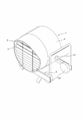
- FIG. 1 is a schematic configuration diagram showing an infrared radiation heater 1 according to an embodiment of the present invention.
- the infrared radiation heater 1 includes a radiator 2 that radiates radiant heat, a louver 3 that controls the direction of radiant heat and warm air from the radiator 2, a combustion chamber 21 and a combustion device described later. 6 and the like, and a frame 5 that supports the case 4.
- the infrared radiation heater 1, the combustion chamber 21, and the combustion device 6 correspond to “infrared radiation heater”, “combustion chamber”, and “combustion device” described in the claims, respectively.
- the frame 5 includes a side support 51 that supports the case 4 from both sides, and a pair of wheels 53 that are provided at the bottom of the frame 5 and assist the transport operation when the infrared radiation heater 1 is transported. .
- FIG. 2 is a front view of the infrared radiation heater 1.
- FIG. 3 is a side sectional view of the infrared radiation heater 1.
- the infrared radiation heater 1 includes a combustion chamber 21 provided inside the case 4, and a combustion device 6 that burns fuel in a central portion in the combustion space 22 of the combustion chamber 21. .
- the combustion chamber 21 is made of a highly heat-insulating material such as a heat insulating material.
- the combustion chamber 21 has a bottom portion and an open portion at one position facing the bottom portion.
- the combustion chamber 21 has a combustion space 22 as a space in which the combustion device 6 burns fuel.
- the combustion chamber 21 has a truncated cone shape in which the bottom portion has a substantially circular shape and the side surface is inclined from the bottom portion toward the open portion.
- the shape of the combustion chamber is not limited to the above-described shape as long as it has a bottom portion, a side surface, and an open portion.
- the radiator 2 is a substantially dome-shaped member having a convex surface with respect to the direction of infrared radiation on the side opposite to the combustion chamber 21, which is provided in the open portion of the combustion chamber 21.
- the radiator 2 is made of a material excellent in infrared emissivity, for example, heat-resistant stainless steel.
- the radiator 2 is formed such that the shape of the radiation surface that radiates heat matches the shape of the open portion of the combustion chamber 21.
- the radiator 2 is reddish by heat from the flame generated by the combustion device 6, and infrared rays are radiated to the outside from the radiation surface.
- the shape of the radiation surface is not limited to the dome shape as described above.
- FIG. 4 is a side view of the combustion device 6 of the infrared radiation heater 1.
- the combustion device 6 includes a burner head portion 60, a fan 7, and a gas pipe connection portion 8.
- the burner head unit 60 burns an air-fuel mixture obtained by mixing the propane gas introduced from the gas pipe connection unit 8 and the air sent from the fan 7 in the combustion space 22 outside the burner head unit 60.
- the fan 7 has an outlet connected to one end of the burner head 60 and sends air necessary for fuel to burn in the combustion device 6.
- FIG. 5 is a side view showing the burner head portion 60 of the combustion device 6.
- 6 is a front view of the burner head unit 60
- FIG. 7 is a rear view of the burner head unit 60
- FIG. 8 is a plan view of the burner head unit.
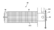
- the burner head unit 60 includes a cylinder 61, a gap 62, an ignition device 63, a mixer unit 64, a nozzle 65, a heat insulating unit 66, and a swirling flow generating unit 67. , A blade 68 and a frame rod 69.
- the cylinder 61 is configured using, for example, a heat-resistant metal.
- the cylindrical body 61 has a base portion 612 provided at one end located on the nozzle 65 side and a heat insulating portion 66 on the other end side located on the opposite side as a bottom surface, and a surface connected to both bottom surfaces as side surfaces. It is a columnar body.
- the cylindrical body 61 has a space inside that is surrounded by a bottom surface and side surfaces.
- the cylindrical body 61 has a bottom surface that is substantially parallel to the radiation surface of the radiator 2.
- the cylindrical body 61 has a side surface that is substantially perpendicular to the radiation surface of the radiator 2.
- the direction of the side surface of the cylindrical body 61 is not limited to being substantially perpendicular to the direction of the radiation surface of the radiator 2, and is predetermined with respect to the radiation surface so that the flame can be spread with respect to the radiation surface of the radiator 2. Any direction with any angle may be used.
- the gap 62 is provided on the side surface of the cylindrical body 61.
- the gap 62 is a fine round hole that is evenly opened from the center of the side surface of the cylindrical body 61 to a region near the heat insulating portion 66 at the other end.
- the shape of the gap 62 is not limited to a fine round hole as shown in FIG. 5, but may be, for example, a square hole or a slit-like pore. Further, the size of the gap 62 and the interval between the positions where the gap 62 is provided may not be uniform. Further, the gap 62 is not limited to a hole formed in the side surface of the cylindrical body 61 formed of a metal plate as shown in FIG. 5, and for example, the side surface of the cylindrical body 61 is made fine such as a metal knit or a sintered product. You may implement
- the ignition device 63 is provided along the outer side, for example, the side surface of the cylindrical body 61.
- the ignition device 63 is provided in a base portion 612 provided on one end side of the cylindrical body 61, for example.
- the ignition device 63 is an ignition plug including an electrode (electrode) that generates a spark by electricity, for example.
- the mixer section 64 is a hollow columnar body that connects the cylindrical body 61 and the fan 7 so as to be able to circulate.
- the mixer unit 64 can cause the air from the fan 7 to flow into the internal space.
- the mixer unit 64 is provided with a nozzle 65.
- the mixer unit 64 is provided with an overheat preventer 641 that detects a flame when fuel is ignited inside the cylinder 61 or the mixer unit 64 and internal ignition occurs. .
- the nozzle 65 is provided inside the mixer unit 64.
- the nozzle 65 is inserted into the mixer unit 64 from the side of the mixer unit 64.
- a hole is formed in the nozzle 65 and fuel is injected into the mixer section 64.
- the shape of the nozzle 65 is also suitable for injecting propane gas.
- the shape of the nozzle 65 is preferably set to be suitable for injecting other fuel such as kerosene.
- the heat insulating portion 66 is provided on the bottom surface on the other end side of the cylindrical body 61. As shown in FIG. 3, in the combustion space 22, the heat insulating portion 66 is provided at a position facing the inner surface of the radiator 2.
- the heat insulating portion 66 is formed using a material having excellent heat insulating properties such as rock wool, alumina fiber, or ceramic. The heat insulating portion 66 insulates between the cylindrical body 61 and the radiator 2 so that heat from the radiator 2 is not transmitted to the cylindrical body 61.
- the swirl flow generator 67 is formed of, for example, a metal plate material.
- the swirl flow generation unit 67 is provided, for example, in the air flow path at a position near the fan 7 of the mixer section 64, specifically, at a position closer to the fan 7 than the nozzle 65.
- the swirl flow generating unit 67 has blades 68 formed on the air flow path in order to generate a swirl flow in the air-fuel mixture flowing through the cylinder 61.
- the blades 68 are formed by making cuts in a substantially rectangular shape leaving four corners in the plate material forming the swirl flow generating portion 67 and changing the direction of the separated portion of the plate material. Yes.
- the blade 68 is further cut into the vicinity of the midpoint of each side of the cut portion with the swirl flow generating portion 67, so that four substantially rectangular blades are formed.
- the individual blades 68 are not separated from each other at the central portion where the corners of the four blades 68 are in contact.
- the swirl flow generation unit 67 has a flow path between the four corners of the blades 68 that are not separated from the swirl flow generation unit 67 and a portion where the four blades 68 are not separated from each other.
- the number and shape of the blades 68 and the shape of the flow path are the same as those in the present embodiment. It is not limited. Further, the blade 68 is not limited to a fixed plate material as in the present embodiment, and may be, for example, a rotary blade that rotates about an axis. Moreover, the position of the blade
- the frame rod 69 is provided along the outer side, for example, the side surface of the cylindrical body 61.
- the frame rod 69 is provided on the base portion 612 to which one end of the cylindrical body 61 is attached, for example.
- the frame rod 69 is formed using a heat-resistant steel material or the like.
- the frame rod 69 detects the presence / absence of a flame based on the change in the current flowing through the steel material due to the presence / absence of a flame.
- FIG. 9 is a side sectional view of the burner head portion 60.
- a mesh 613 is provided inside the cylindrical body 61 of the burner head portion 60 along the inner wall.
- the mesh 613 is a heat-resistant metal mesh, for example, and prevents a flame from entering the inside of the cylindrical body 61 from the gap 62. Further, the mesh 613 can prevent dust from the outside from entering the combustion device 6. In addition, the mesh 613 can also make an appropriate amount of air-fuel mixture that exits from the cylindrical body 61 through the gap 62.
- the infrared radiation heater 1 the gas sent from the gas pipe connection portion 8 is ejected from the nozzle 65 and air is sent from the fan 7 to the mixer portion 64.
- the air sent from the fan 7 generates a swirl flow by the blades 68 of the swirl flow generation unit 67, so that the air is mixed well with the gas from the nozzle 65.
- the unevenness of the flame is reduced and the unevenness of the heat transmitted to the radiator 2 can be reduced.
- the air-fuel mixture mixed by the mixer unit 64 flows into the inside from one end of the cylindrical body 61.
- the air-fuel mixture sent to the inside of the cylindrical body 61 spreads in a predetermined direction along the radiation surface of the radiator 2 by a plurality of minute gaps 62 formed on the side surface of the cylindrical body 61, and the outside of the cylindrical body 61. That is, it is discharged into the combustion space 22 of the combustion chamber 21.
- the air-fuel mixture released into the combustion space 22 is ignited by a spark generated by an ignition device 63 provided outside the cylinder 61.
- the ignited air-fuel mixture spreads in a direction having a predetermined angle such as a direction along the radiation surface of the radiator 2 and burns to form a flame.
- the flame hardly enters the inside of the cylinder 61 due to the mesh 613 and the gap 62 provided inside the cylinder 61. For this reason, in the infrared radiation heater 1, a phenomenon in which the gas burns inside the cylinder body 61 due to the flame that enters the cylinder body 61, that is, so-called backfire hardly occurs.
- Radiator 2 is entirely heated and reddish by a flame spreading in the direction along the radiation surface of radiator 2.
- the radiator 2 emits infrared rays from the entire surface to the outside.
- the air-fuel mixture flows into the inside from one end of the cylindrical body 61 located on the nozzle 65 side.
- the side surface of the cylindrical body 61 faces a direction having a predetermined angle with respect to the radiation surface of the radiator 2.
- the air-fuel mixture is discharged into the combustion chamber 21 through a plurality of minute gaps 62 provided on the side surface of the cylinder body 61.
- a flame can be generated in a direction along the radiation surface of the radiator 2. Therefore, the infrared radiation efficiency is improved by heating the entire surface of the radiator 2 uniformly. Can be made.
- the flame can be prevented from returning to the inside of the cylindrical body 61 by the plurality of minute gaps 62.
- the infrared radiation heater 1 includes a heat insulating portion 66 that is provided at the other end of the cylinder 61 of the combustion device 6 and insulates between the cylinder 61 and the radiator 2. According to such an infrared radiation heater 1, since the heat radiated from the radiator 2 is difficult to be transmitted to the cylinder 61, it is possible to prevent the air-fuel mixture inside the cylinder 61 from being heated and causing backfire. Further, in the infrared radiation heater 1, by providing the heat insulating portion 66, it is possible to reduce deterioration of the tip of the cylindrical body 61 due to heat transmitted from the radiator 2.
- the infrared radiation heater 1 is provided with blades 68 for generating a swirling flow in the air-fuel mixture flowing inside the cylindrical body 61 in the air flow path. According to such an infrared radiation heater 1, an air-fuel mixture in which gas and air are mixed well is generated, so that the combustion state of the gas can be improved.
- the infrared radiation heater 1 can improve the gas combustion state without providing moving parts because the blades 68 are fixed plate members.
- the infrared radiation heater 1 since the gap 62 is formed over the entire circumferential direction of the side surface of the cylindrical body 61, a flame is generated in a direction along the radiation surface of the radiator 2, and the entire radiation surface of the radiator 2. Can be heated uniformly.
- the infrared radiation heater 1 can prevent the flame from returning to the inside of the cylindrical body 61 because the mesh 613 inside the cylindrical body 61 forms the gap 62 in a mesh shape. In addition, the infrared radiation heater 1 can prevent the dust from the outside from entering the combustion device 6 and causing a trouble by the mesh 613.
- the infrared radiation heater described above can also be applied to a heater that burns fuel other than the above-mentioned propane gas and kerosene, for example, natural gas.
Landscapes
- Engineering & Computer Science (AREA)
- Chemical & Material Sciences (AREA)
- Combustion & Propulsion (AREA)
- Mechanical Engineering (AREA)
- General Engineering & Computer Science (AREA)
- Physics & Mathematics (AREA)
- Thermal Sciences (AREA)
- Gas Burners (AREA)
- Pre-Mixing And Non-Premixing Gas Burner (AREA)
Abstract
Priority Applications (5)
| Application Number | Priority Date | Filing Date | Title |
|---|---|---|---|
| EP16925267.3A EP3531797B1 (fr) | 2016-12-27 | 2016-12-27 | Dispositif de chauffage par rayonnement infrarouge |
| US16/301,182 US11041618B2 (en) | 2016-12-27 | 2016-12-27 | Infrared radiation heater |
| CA3024292A CA3024292C (fr) | 2016-12-27 | 2016-12-27 | Dispositif de chauffage par rayonnement infrarouge |
| PCT/JP2016/088844 WO2018122948A1 (fr) | 2016-12-27 | 2016-12-27 | Dispositif de chauffage par rayonnement infrarouge |
| JP2018558554A JP7014942B2 (ja) | 2016-12-27 | 2016-12-27 | 赤外線放射ヒータ |
Applications Claiming Priority (1)
| Application Number | Priority Date | Filing Date | Title |
|---|---|---|---|
| PCT/JP2016/088844 WO2018122948A1 (fr) | 2016-12-27 | 2016-12-27 | Dispositif de chauffage par rayonnement infrarouge |
Publications (1)
| Publication Number | Publication Date |
|---|---|
| WO2018122948A1 true WO2018122948A1 (fr) | 2018-07-05 |
Family
ID=62707095
Family Applications (1)
| Application Number | Title | Priority Date | Filing Date |
|---|---|---|---|
| PCT/JP2016/088844 WO2018122948A1 (fr) | 2016-12-27 | 2016-12-27 | Dispositif de chauffage par rayonnement infrarouge |
Country Status (5)
| Country | Link |
|---|---|
| US (1) | US11041618B2 (fr) |
| EP (1) | EP3531797B1 (fr) |
| JP (1) | JP7014942B2 (fr) |
| CA (1) | CA3024292C (fr) |
| WO (1) | WO2018122948A1 (fr) |
Cited By (2)
| Publication number | Priority date | Publication date | Assignee | Title |
|---|---|---|---|---|
| KR102619832B1 (ko) * | 2023-06-21 | 2023-12-29 | 권순성 | 예혼합 연소 방식의 메탈화이버 가스버너를 적용한 온풍 및 탄산가스 공급장치 |
| KR102649269B1 (ko) * | 2023-06-21 | 2024-03-18 | 권순성 | 예혼합 연소 방식의 메탈화이버 가스버너를 적용한 온풍 및 탄산가스 공급장치 |
Citations (6)
| Publication number | Priority date | Publication date | Assignee | Title |
|---|---|---|---|---|
| JPS62297615A (ja) * | 1986-06-16 | 1987-12-24 | Matsushita Electric Ind Co Ltd | 燃焼装置 |
| JPH0136004B2 (fr) * | 1983-06-24 | 1989-07-28 | Matsushita Electric Ind Co Ltd | |
| JPH02230027A (ja) * | 1989-03-02 | 1990-09-12 | Matsushita Electric Ind Co Ltd | 輻射式暖房装置 |
| JPH03233230A (ja) * | 1990-02-07 | 1991-10-17 | Matsushita Electric Ind Co Ltd | 輻射式暖房装置 |
| JP2004270956A (ja) | 2003-03-05 | 2004-09-30 | Shizuoka Seiki Co Ltd | 赤外線輻射ヒータ |
| JP2010133568A (ja) * | 2008-12-02 | 2010-06-17 | Shizuoka Seiki Co Ltd | 赤外線輻射ヒータ |
Family Cites Families (20)
| Publication number | Priority date | Publication date | Assignee | Title |
|---|---|---|---|---|
| US1017760A (en) * | 1910-05-02 | 1912-02-20 | Frank Voigtmann | Fireproof window with detachable munnion-bars. |
| US1427371A (en) * | 1922-04-22 | 1922-08-29 | Garbarini Andre | Radiator for gas heating by incandescence |
| US3179156A (en) * | 1962-01-17 | 1965-04-20 | American Thermocatalytic Corp | Space heater |
| US3245458A (en) | 1962-12-11 | 1966-04-12 | Hupp Corp | Radiant gas burner |
| BE652651A (fr) * | 1963-09-03 | |||
| US3269449A (en) * | 1964-09-21 | 1966-08-30 | American Radiator & Standard | Burner apparatus |
| US3349752A (en) * | 1966-03-31 | 1967-10-31 | Raymond E Murphy | Poultry brooder |
| US3726633A (en) | 1970-11-30 | 1973-04-10 | Thermo Electron Corp | Low pollutant-high thermal efficiency burner |
| US3975140A (en) * | 1974-08-28 | 1976-08-17 | International Magna Corporation | Space heater |
| JPS5343025U (fr) * | 1976-09-18 | 1978-04-13 | ||
| IT1141852B (it) * | 1980-03-12 | 1986-10-08 | Silvio Polidoro | Bruciatore a gas,a raggi infrarossi rivolti verso il basso |
| JPS58182020A (ja) * | 1982-04-19 | 1983-10-24 | Matsushita Electric Ind Co Ltd | 燃焼装置 |
| US5017129A (en) * | 1990-02-06 | 1991-05-21 | Scheu Manufacturing Company | Porous ceramic gas burner |
| US5417389A (en) * | 1993-02-19 | 1995-05-23 | Radiant Energy Corporation | Method of, and apparatus for, de-icing an aircraft by infrared radiation |
| KR960029711A (ko) * | 1995-01-25 | 1996-08-17 | 해롤드 제이. 화운츠 | 복사 가열기 |
| JPH1036004A (ja) | 1996-07-17 | 1998-02-10 | Toshiba Corp | 可撓性長尺体の処理装置 |
| FR2763670B1 (fr) * | 1997-05-23 | 1999-08-20 | 4E Systel | Appareil de chauffage au gaz, notamment pour les batiments d'elevage |
| US20040152028A1 (en) * | 2003-02-05 | 2004-08-05 | Singh Prem C. | Flame-less infrared heater |
| US8122875B2 (en) * | 2003-12-29 | 2012-02-28 | Lg Electronics Inc. | Burner assembly for gas burners of radiant heating type |
| US9080773B2 (en) * | 2008-03-27 | 2015-07-14 | Schwank Ltd. | Pitot tube pressure sensor for radiant tube heater |
-
2016
- 2016-12-27 CA CA3024292A patent/CA3024292C/fr active Active
- 2016-12-27 EP EP16925267.3A patent/EP3531797B1/fr active Active
- 2016-12-27 JP JP2018558554A patent/JP7014942B2/ja active Active
- 2016-12-27 WO PCT/JP2016/088844 patent/WO2018122948A1/fr unknown
- 2016-12-27 US US16/301,182 patent/US11041618B2/en active Active
Patent Citations (6)
| Publication number | Priority date | Publication date | Assignee | Title |
|---|---|---|---|---|
| JPH0136004B2 (fr) * | 1983-06-24 | 1989-07-28 | Matsushita Electric Ind Co Ltd | |
| JPS62297615A (ja) * | 1986-06-16 | 1987-12-24 | Matsushita Electric Ind Co Ltd | 燃焼装置 |
| JPH02230027A (ja) * | 1989-03-02 | 1990-09-12 | Matsushita Electric Ind Co Ltd | 輻射式暖房装置 |
| JPH03233230A (ja) * | 1990-02-07 | 1991-10-17 | Matsushita Electric Ind Co Ltd | 輻射式暖房装置 |
| JP2004270956A (ja) | 2003-03-05 | 2004-09-30 | Shizuoka Seiki Co Ltd | 赤外線輻射ヒータ |
| JP2010133568A (ja) * | 2008-12-02 | 2010-06-17 | Shizuoka Seiki Co Ltd | 赤外線輻射ヒータ |
Non-Patent Citations (1)
| Title |
|---|
| See also references of EP3531797A4 |
Cited By (2)
| Publication number | Priority date | Publication date | Assignee | Title |
|---|---|---|---|---|
| KR102619832B1 (ko) * | 2023-06-21 | 2023-12-29 | 권순성 | 예혼합 연소 방식의 메탈화이버 가스버너를 적용한 온풍 및 탄산가스 공급장치 |
| KR102649269B1 (ko) * | 2023-06-21 | 2024-03-18 | 권순성 | 예혼합 연소 방식의 메탈화이버 가스버너를 적용한 온풍 및 탄산가스 공급장치 |
Also Published As
| Publication number | Publication date |
|---|---|
| EP3531797A1 (fr) | 2019-08-28 |
| CA3024292C (fr) | 2020-04-28 |
| US20190309944A1 (en) | 2019-10-10 |
| JPWO2018122948A1 (ja) | 2019-10-31 |
| EP3531797A4 (fr) | 2020-01-01 |
| CA3024292A1 (fr) | 2018-07-05 |
| EP3531797B1 (fr) | 2021-12-01 |
| JP7014942B2 (ja) | 2022-02-02 |
| US11041618B2 (en) | 2021-06-22 |
Similar Documents
| Publication | Publication Date | Title |
|---|---|---|
| US10544961B2 (en) | Premix burner internal flue shield | |
| TWI570369B (zh) | Output heat source temperature controllable combustion device | |
| US9068760B2 (en) | Heating appliance for air heating | |
| TW201812218A (zh) | 燃燒器的點火裝置 | |
| WO2018122948A1 (fr) | Dispositif de chauffage par rayonnement infrarouge | |
| JPH0435649B2 (fr) | ||
| JP2006501428A (ja) | 多孔質バーナー、及び少なくとも1つの多孔質バーナーを含む調理器具 | |
| GB1382553A (en) | Fuel-fired infra-red heater | |
| KR101215090B1 (ko) | 연소 가열기 | |
| JP6099452B2 (ja) | 赤外線燃焼装置 | |
| KR100844124B1 (ko) | 링형 버너 | |
| JPWO2007061055A1 (ja) | バーナの燃焼効率向上化装置 | |
| KR101830501B1 (ko) | 분사노즐과 이를 갖춘 버너 | |
| KR100739541B1 (ko) | 가스 복사 버너 | |
| AU2003260541B2 (en) | Food cooking oven | |
| JPS591917A (ja) | 加熱用燃焼装置 | |
| JPH06241419A (ja) | 環状火炎式のラジアントチューブバーナ | |
| JP2593892B2 (ja) | 炉装置 | |
| JP2000274608A (ja) | バーナー | |
| KR200247321Y1 (ko) | 난방기기용 가스 버너 | |
| JP2005291666A (ja) | 燃焼機器 | |
| JPS63279010A (ja) | 燃焼装置 | |
| RU2165562C1 (ru) | Многофакельная горелка | |
| JP2982451B2 (ja) | 液体燃料燃焼装置 | |
| JP2005257185A (ja) | ガスコンロ |
Legal Events
| Date | Code | Title | Description |
|---|---|---|---|
| ENP | Entry into the national phase |
Ref document number: 2018558554 Country of ref document: JP Kind code of ref document: A |
|
| ENP | Entry into the national phase |
Ref document number: 3024292 Country of ref document: CA |
|
| 121 | Ep: the epo has been informed by wipo that ep was designated in this application |
Ref document number: 16925267 Country of ref document: EP Kind code of ref document: A1 |
|
| ENP | Entry into the national phase |
Ref document number: 2016925267 Country of ref document: EP Effective date: 20190523 |
|
| NENP | Non-entry into the national phase |
Ref country code: DE |