US5017129A - Porous ceramic gas burner - Google Patents
Porous ceramic gas burner Download PDFInfo
- Publication number
- US5017129A US5017129A US07/475,964 US47596490A US5017129A US 5017129 A US5017129 A US 5017129A US 47596490 A US47596490 A US 47596490A US 5017129 A US5017129 A US 5017129A
- Authority
- US
- United States
- Prior art keywords
- ceramic
- burner
- wall
- air
- cavity
- Prior art date
- Legal status (The legal status is an assumption and is not a legal conclusion. Google has not performed a legal analysis and makes no representation as to the accuracy of the status listed.)
- Expired - Lifetime
Links
- 239000000919 ceramic Substances 0.000 title claims abstract description 72
- 239000000203 mixture Substances 0.000 claims abstract description 31
- 238000002485 combustion reaction Methods 0.000 claims abstract description 14
- 230000002093 peripheral effect Effects 0.000 claims description 39
- 239000000446 fuel Substances 0.000 claims description 28
- 238000010791 quenching Methods 0.000 claims description 2
- 238000009877 rendering Methods 0.000 claims description 2
- 239000007789 gas Substances 0.000 description 9
- 238000010276 construction Methods 0.000 description 6
- 238000010438 heat treatment Methods 0.000 description 3
- ATUOYWHBWRKTHZ-UHFFFAOYSA-N Propane Chemical compound CCC ATUOYWHBWRKTHZ-UHFFFAOYSA-N 0.000 description 2
- 239000000835 fiber Substances 0.000 description 2
- 238000004519 manufacturing process Methods 0.000 description 2
- 239000002184 metal Substances 0.000 description 2
- VNWKTOKETHGBQD-UHFFFAOYSA-N methane Chemical compound C VNWKTOKETHGBQD-UHFFFAOYSA-N 0.000 description 2
- 238000012986 modification Methods 0.000 description 2
- 230000004048 modification Effects 0.000 description 2
- 230000006641 stabilisation Effects 0.000 description 2
- 238000011105 stabilization Methods 0.000 description 2
- 229910010293 ceramic material Inorganic materials 0.000 description 1
- 238000004891 communication Methods 0.000 description 1
- 238000007599 discharging Methods 0.000 description 1
- 238000009413 insulation Methods 0.000 description 1
- 239000003345 natural gas Substances 0.000 description 1
- 239000001294 propane Substances 0.000 description 1
- 230000000717 retained effect Effects 0.000 description 1
- 230000035939 shock Effects 0.000 description 1
- 238000009827 uniform distribution Methods 0.000 description 1
Images

Classifications
-
- F—MECHANICAL ENGINEERING; LIGHTING; HEATING; WEAPONS; BLASTING
- F23—COMBUSTION APPARATUS; COMBUSTION PROCESSES
- F23D—BURNERS
- F23D14/00—Burners for combustion of a gas, e.g. of a gas stored under pressure as a liquid
- F23D14/46—Details, e.g. noise reduction means
- F23D14/48—Nozzles
- F23D14/58—Nozzles characterised by the shape or arrangement of the outlet or outlets from the nozzle, e.g. of annular configuration
-
- F—MECHANICAL ENGINEERING; LIGHTING; HEATING; WEAPONS; BLASTING
- F23—COMBUSTION APPARATUS; COMBUSTION PROCESSES
- F23D—BURNERS
- F23D14/00—Burners for combustion of a gas, e.g. of a gas stored under pressure as a liquid
- F23D14/46—Details, e.g. noise reduction means
- F23D14/72—Safety devices, e.g. operative in case of failure of gas supply
- F23D14/82—Preventing flashback or blowback
Definitions
- the present invention generally relates to a quiet, compact and efficient burner for use with forced air heaters. More specifically, the invention relates to a porous ceramic gas burner constructed from ceramic blocks associated with each other to form a hollow chamber to receive naturally aspirated gas and air mixture from a venturi with the ceramic blocks including a plurality of small holes enabling passage of the gas and air mixture to the outer periphery of the burner for ignition and combustion with the structural characteristics of the small holes preventing flashback of flame even though the velocity of the air and gas mixture is less than the flame propagation rate thereby reducing the noise level of the burner by reducing the velocity of the air gas mixture passing through the burner.
- the burner is associated with a forced air heater including a fan and a duct associated therewith to direct forced secondary air over the periphery of the burner with the periphery of the burner including a surface generally parallel to the flow path of the secondary air with the holes in the burner being perpendicular to the flow path of the secondary air.
- An object of the present invention is to provide a porous ceramic gas burner for use with a portable forced air heater or the like which includes a porous ceramic burner having a porous ceramic peripheral wall defining a hollow interior cavity communicated with a source of mixed primary air and gaseous fuel at one side of the cavity with the other side of the cavity being closed by an endplate thereby requiring the primary air and gaseous fuel mixture to exit through the porous peripheral wall for combustion on and adjacent to the outer peripheral surface of the porous peripheral wall with forced secondary air flowing across the exterior surface and adjacent area of the peripheral wall in perpendicular relation to the path of flow of the air and gas mixture through the porous peripheral wall to provide secondary combustion air and convection circulation of heated air.
- Another object of the invention is to provide a burner in accordance with the preceding object in which the peripheral ceramic wall is constructed of a plurality of segments to facilitate manufacture and assembly with the peripheral wall including a plurality of small holes extending from the inner cavity to the external periphery of the wall in which the holes are constructed in a manner to prevent flame flashback thus enabling the primary air and gaseous fuel mixture to pass through the holes at a low velocity less than the flame propagation rate thereby reducing the noise level of the burner.
- a further object of the present invention is to provide a burner in accordance with the preceding objects in which the small holes in the ceramic peripheral wall are uniformly spaced and provide approximately a 40% flow area with the ceramic wall being approximately 1/2" thick and the hole diameter being approximately 0.050" in diameter.
- Still another object of the invention is to provide a burner in accordance with the preceding objects which is efficient in operation, compact in size compared to the heating capacity of the burner and which produces a low noise level during operation thereby rendering the burner especially useful in a portable forced air heater.
- FIG. 1 is a sectional view of a portable, forced air heater with the burner of the present invention incorporated therein.
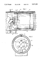
- FIG. 2 is a transverse, sectional view taken substantially upon a plane passing along section line 2--2 on FIG. 1 illustrating the association of the burner with the other components of the forced air heater.
- FIG. 3 is a perspective view of the burner including the venturi, end plates and ceramic blocks.
- FIG. 4 is a vertical, sectional view taken substantially upon a plane passing along section line 4--4 on FIG. 3 illustrating specific structural details of the burner.
- FIG. 5 is a perspective view of the ceramic blocks assembled to form a square peripheral wall of the burner.
- FIG. 6 is a perspective view similar to FIG. 5 but illustrating a ceramic wall of cylindrical configuration.
- the porous, ceramic gas burner of the present invention is generally designated by reference numeral 10 and is illustrated in detail in FIGS. 3-6.
- the burner 10 of this invention is shown incorporated into a portable forced air heater generally designated by reference numeral 12 in FIGS. 1 and 2 which includes a housing 14 of cylindrical configuration provided with support structure 16.
- the interior of the housing 14 includes a fan 18 driven by an electric motor (not shown) with the housing 14 also including an open end 18 for discharging heat.
- This type of heater is well-known, except for burner 10, and is disclosed in detail in Pat. No. 3,494,599.
- a cylindrical liner 20 is supported in the housing 14 and a gaseous fuel nozzle 22 is associated with the inlet venturi tube 24 of the burner 10 in a manner to provide an entrance area 26 for primary air to be mixed with the gaseous fuel discharged from the nozzle 22 in a conventional manner with the burner and venturi 24 being supported by a bracket structure 28 in the form of a plate having a large central opening 30 providing a passageway for forced secondary air from the fan 18 over the burner 10 with suitable controls also being provided to control operation of the burner and fan in accordance with the above-mentioned patent.
- the burner 10 of this invention includes a peripheral ceramic wall generally designated by reference numeral 32 which includes a hollow interior forming a cavity 34 that extends from one end to the other of the wall 32.
- One end of the cavity 34 is closed by a flat, imperforate inlet end plate 36 that is rigidly affixed to the end of the venturi as illustrated in FIGS. 3 and 4.
- the other end of the cavity 34 is closed by an imperforate end plate 38.
- the peripheral ceramic wall 32 is positioned between the plates 36 and 38 with the cavity 34 in communication with the interior of the venturi 24 to receive a mixture of gaseous fuel and primary air.
- venturi 24 is supported by support tabs or brackets 40 connected with the bracket structure 28 and the end plate 38 is secured to the end plate 36 by a plurality of screw threaded fasteners 42 in the form of bolts or the like to retain the peripheral ceramic wall 32 in assembled relation to the end plates.
- the peripheral ceramic wall 32 is constructed from four identical, generally rectangular ceramic blocks 44 which include mitered ends 46 oriented at 45° angles to provide a square ceramic wall 32 with the cavity 34 being square and the plates 36 and 38 being correspondingly square.
- Each block includes a plurality of small holes 48 extending from the cavity 34 to the peripheral surface thereof and the end plates 36 and 38 include corner tabs 50 which engage the external surfaces of the blocks to retain them in assembled relation as illustrated in FIGS. 3 and 4.
- Each of the blocks 44 has a thickness of approximately 3/8" to 3/4" with blocks of 1/2" thickness being a preferred dimension.
- the small holes 48 provide a flow area through the ceramic elements between 30% and 60% with the preferred porosity being 40%.
- the holes 48 are preferably cylindrical in configuration and are preferably 0.050" in diameter.
- the outside corner edges of the ceramic blocks may also be chamfered to facilitate handling and reduce sharp edges if desired.
- the ceramic peripheral wall 32 formed by the blocks 44 is of square configuration but, as illustrated in FIG. 6, it is also within the purview of the present invention to provide a ceramic peripheral wall 62 of cylindrical configuration with the cavity 64 also being cylindrical.
- the ceramic wall 62 may be segmental or of one-piece unitary construction. The unitary construction of a peripheral wall 32 or 62 is preferred but, from a manufacturing standpoint, the segmental peripheral wall may be more economical.
- the ceramic burner 10 as illustrated in FIG. 1 receives a mixture of primary air and gaseous fuel from the nozzle 22 which discharges gaseous fuel such as natural gas or propane into the inlet 26 of the venturi tube 24.
- gaseous fuel such as natural gas or propane
- the high velocity fuel entrains surrounding air molecules to provide naturally aspirated primary air into the venturi tube where it mixes with the gaseous fuel.
- the fuel and air mixture passes through the venturi tube 24 into the cavity or chamber 34 which is defined by the plate 36, plate 38 and the four porous ceramic blocks 44 or the ceramic wall 62.
- the porous ceramic blocks 44 form the periphery of the square burner with the small holes 48 providing a flow path for the mixture of fuel and primary air which exits into the combustion area around the periphery of the ceramic wall 32.
- Secondary air provided by the fan 18 is forced through the large hole 30 and over the periphery of the ceramic wall 32.
- the combustible mixture which is ignited by a suitable ignition device 66 encounters the secondary air for efficient combustion and to provide a heat source for the heater.
- the combustion is efficient thus providing a clean, compact and quiet burner due to the pervasive and uniform distribution of the relatively low velocity primary air and fuel mixture thereby resulting in a substantial reduction in combustion noise without a substantial change in heater efficiency, output or size.
- the structural characteristics of the ceramic peripheral wall are matched to the inlet characteristics of the nozzle and venturi tube which in turn are matched to the desired heater output.
- the burner size varies in accordance with the desired heat output and the structure of the ceramic peripheral wall including its thickness, hole size and porosity corresponds with the desired performance characteristics.
- the hole size and thickness is sufficient to prevent flashback of flame through the ceramic blocks thereby preventing any ignition or combustion in the venturi or cavity 34.
- the hole size is such that flashback is prevented by the flame being quenched which enables the velocity of the fuel and air mixture passing through the porous ceramic wall to be reduced below the flame propagation rate of the fuel and air mixture.
- the end plates 36 and 38 are of metal construction and the ceramic blocks 44 are cushioned by a ceramic fiber mat 68 in the form of a strip which is positioned between the edges of the blocks 44 and the end plates 36 and 38, respectively, as illustrated in FIG. 4 to protect the fragile blocks from mechanical shock and also provide an insulation between the end edges of the blocks and the metal end plates 36 and 38.
- the fastener bolts 42 may be of any suitable construction and the number of bolts may vary depending upon the size characteristics of the burner.
- the low velocity of the fuel and air mixture and its ignition and stabilization along the outer surface of the peripheral ceramic wall provides a less turbulent laminar flame around the periphery of the ceramic wall as compared to a relatively high velocity conventional burner.
- the lowered velocity of the primary air and fuel mixture provides lower shear forces and increases the flame front to encourage mixing with the secondary air.
- the ceramic blocks or elements 44 are essentially rectangular blocks with the two ends beveled or chamfered at 45° with the blocks being retained in the square pattern by the end plates 36 and 38 with the tabs 50 on the end plates, the fasteners 42 and the ceramic fiber strips 68 cooperating to provide a quickly and easily assembled unit which is leak tight with the venturi being sized for the intended burn rate and compatible with the fuel nozzle 22.
- the fuel and air mixture passes through the venturi, which can be oriented in any desired relation to the housing, into cavity 34 and passes in a direction parallel to the end plates through the small holes to the peripheral surface of the peripheral ceramic wall with the mounting plate 28 also serving as a baffle or flame holder plate to provide a quiescent zone for flame stabilization and propagation on and along and adjacent the peripheral surface of the peripheral wall 32 which results in a very substantial reduction in noise level without a change in heater size or performance.
Landscapes
- Engineering & Computer Science (AREA)
- Chemical & Material Sciences (AREA)
- Combustion & Propulsion (AREA)
- Mechanical Engineering (AREA)
- General Engineering & Computer Science (AREA)
- Gas Burners (AREA)
Abstract
Description
Claims (11)
Priority Applications (1)
| Application Number | Priority Date | Filing Date | Title |
|---|---|---|---|
| US07/475,964 US5017129A (en) | 1990-02-06 | 1990-02-06 | Porous ceramic gas burner |
Applications Claiming Priority (1)
| Application Number | Priority Date | Filing Date | Title |
|---|---|---|---|
| US07/475,964 US5017129A (en) | 1990-02-06 | 1990-02-06 | Porous ceramic gas burner |
Publications (1)
| Publication Number | Publication Date |
|---|---|
| US5017129A true US5017129A (en) | 1991-05-21 |
Family
ID=23889928
Family Applications (1)
| Application Number | Title | Priority Date | Filing Date |
|---|---|---|---|
| US07/475,964 Expired - Lifetime US5017129A (en) | 1990-02-06 | 1990-02-06 | Porous ceramic gas burner |
Country Status (1)
| Country | Link |
|---|---|
| US (1) | US5017129A (en) |
Cited By (12)
| Publication number | Priority date | Publication date | Assignee | Title |
|---|---|---|---|---|
| US5408984A (en) * | 1993-07-26 | 1995-04-25 | General Electric Company | Two stage flame stabilization for a gas burner |
| EP0838635A2 (en) | 1996-10-28 | 1998-04-29 | Carrier Corporation | Noise reducing device for combustion driven heating apparatus |
| US6142141A (en) * | 1997-05-05 | 2000-11-07 | The Coleman Company, Inc. | Airflow diffuser for use with a forced-air space heater and a forced-air space heater using the same |
| US20020166553A1 (en) * | 2001-05-09 | 2002-11-14 | Topp Daniel P. | Combustion system for a heater |
| WO2005100856A1 (en) * | 2004-04-06 | 2005-10-27 | Tiax Llc | Burner apparatus |
| US20080268394A1 (en) * | 2007-04-27 | 2008-10-30 | Paloma Industries, Limited | Burner |
| US20080276618A1 (en) * | 2007-05-11 | 2008-11-13 | General Electric Company | Method and system for porous flame holder for hydrogen and syngas combustion |
| US20120003595A1 (en) * | 2009-09-29 | 2012-01-05 | Honeywell International Inc. | High turn down low nox burner |
| US20150192292A1 (en) * | 2012-07-03 | 2015-07-09 | Ulrich Dreizler | Surface combustion burner |
| US20160305653A1 (en) * | 2015-04-17 | 2016-10-20 | Eaton Corporation | Flame arrestor |
| US10036571B1 (en) | 2013-04-12 | 2018-07-31 | Enerco Group, Inc. | Forced air heater burner |
| US11041618B2 (en) * | 2016-12-27 | 2021-06-22 | Shizuoka Seiki Co., Ltd. | Infrared radiation heater |
Citations (6)
| Publication number | Priority date | Publication date | Assignee | Title |
|---|---|---|---|---|
| US4231735A (en) * | 1978-03-13 | 1980-11-04 | Downs Edgar S | Radiant heater |
| US4746286A (en) * | 1986-10-14 | 1988-05-24 | Shell Oil Company | Burner for a gaseous fuel |
| US4825846A (en) * | 1988-01-25 | 1989-05-02 | Joseph Fraioli | Ribbon-type, gas-fired burner head |
| US4838241A (en) * | 1988-08-05 | 1989-06-13 | Rieger Heinz H | Fireplace natural gas and propane burner assembly |
| US4889103A (en) * | 1988-01-25 | 1989-12-26 | Joseph Fraioli | Infrared wok heater |
| US4917599A (en) * | 1988-12-29 | 1990-04-17 | Hasselmann Detley E M | Burner for combustible gases |
-
1990
- 1990-02-06 US US07/475,964 patent/US5017129A/en not_active Expired - Lifetime
Patent Citations (6)
| Publication number | Priority date | Publication date | Assignee | Title |
|---|---|---|---|---|
| US4231735A (en) * | 1978-03-13 | 1980-11-04 | Downs Edgar S | Radiant heater |
| US4746286A (en) * | 1986-10-14 | 1988-05-24 | Shell Oil Company | Burner for a gaseous fuel |
| US4825846A (en) * | 1988-01-25 | 1989-05-02 | Joseph Fraioli | Ribbon-type, gas-fired burner head |
| US4889103A (en) * | 1988-01-25 | 1989-12-26 | Joseph Fraioli | Infrared wok heater |
| US4838241A (en) * | 1988-08-05 | 1989-06-13 | Rieger Heinz H | Fireplace natural gas and propane burner assembly |
| US4917599A (en) * | 1988-12-29 | 1990-04-17 | Hasselmann Detley E M | Burner for combustible gases |
Cited By (21)
| Publication number | Priority date | Publication date | Assignee | Title |
|---|---|---|---|---|
| US5408984A (en) * | 1993-07-26 | 1995-04-25 | General Electric Company | Two stage flame stabilization for a gas burner |
| EP0838635A2 (en) | 1996-10-28 | 1998-04-29 | Carrier Corporation | Noise reducing device for combustion driven heating apparatus |
| US6142141A (en) * | 1997-05-05 | 2000-11-07 | The Coleman Company, Inc. | Airflow diffuser for use with a forced-air space heater and a forced-air space heater using the same |
| US20020166553A1 (en) * | 2001-05-09 | 2002-11-14 | Topp Daniel P. | Combustion system for a heater |
| US6681760B2 (en) | 2001-05-09 | 2004-01-27 | Topp Construction Services, Inc. | Direct-fired heater |
| US20040157180A1 (en) * | 2001-05-09 | 2004-08-12 | Topp Construction Services, Inc. | Combustion system for a heater |
| US6857870B2 (en) | 2001-05-09 | 2005-02-22 | Topp Construction Services, Inc. | Combustion system for a heater |
| US6880549B2 (en) * | 2001-05-09 | 2005-04-19 | Topp Intellectual Properties, Inc. | Combustion system for a heater |
| US7857616B2 (en) | 2004-04-06 | 2010-12-28 | Tiax Llc | Burner apparatus |
| WO2005100856A1 (en) * | 2004-04-06 | 2005-10-27 | Tiax Llc | Burner apparatus |
| US20050250065A1 (en) * | 2004-04-06 | 2005-11-10 | Tiax Llc | Burner apparatus |
| US20080268394A1 (en) * | 2007-04-27 | 2008-10-30 | Paloma Industries, Limited | Burner |
| US20080276618A1 (en) * | 2007-05-11 | 2008-11-13 | General Electric Company | Method and system for porous flame holder for hydrogen and syngas combustion |
| US8413445B2 (en) * | 2007-05-11 | 2013-04-09 | General Electric Company | Method and system for porous flame holder for hydrogen and syngas combustion |
| US20120003595A1 (en) * | 2009-09-29 | 2012-01-05 | Honeywell International Inc. | High turn down low nox burner |
| US20150192292A1 (en) * | 2012-07-03 | 2015-07-09 | Ulrich Dreizler | Surface combustion burner |
| US10605451B2 (en) * | 2012-07-03 | 2020-03-31 | Ulrich Dreizler | Surface combustion burner |
| US10036571B1 (en) | 2013-04-12 | 2018-07-31 | Enerco Group, Inc. | Forced air heater burner |
| US20160305653A1 (en) * | 2015-04-17 | 2016-10-20 | Eaton Corporation | Flame arrestor |
| US10890325B2 (en) * | 2015-04-17 | 2021-01-12 | Eaton Intelligent Power Limited | Flame arrestor |
| US11041618B2 (en) * | 2016-12-27 | 2021-06-22 | Shizuoka Seiki Co., Ltd. | Infrared radiation heater |
Similar Documents
| Publication | Publication Date | Title |
|---|---|---|
| US11402093B2 (en) | Fuel/air mixture and combustion apparatus and associated methods for use in a fuel-fired heating apparatus | |
| US5062788A (en) | High efficiency linear gas burner assembly | |
| US6106276A (en) | Gas burner system providing reduced noise levels | |
| JP2717768B2 (en) | Gas cooking assembly having a gas burner positioned below a single cooking plate of a heat radiating material such as glass ceramic | |
| JP2582728B2 (en) | Vibration resistant low nitrogen oxide burner | |
| US3684424A (en) | Noiseless radiant wall burner | |
| US5017129A (en) | Porous ceramic gas burner | |
| US3805763A (en) | Flush-mountable, self-cooling gas-fired heater | |
| US5975887A (en) | Compact hi-spin gas burner assembly | |
| US6889686B2 (en) | One shot heat exchanger burner | |
| US6059566A (en) | Burner apparatus | |
| CN112944340B (en) | Burner and combustion equipment | |
| GB1314935A (en) | Portable forced air heaters and nozzle assemblies therefor | |
| JPS5826489B2 (en) | High momentum burner | |
| US20040121277A1 (en) | Premixed combustion gas burner having separated fire hole units | |
| US3794014A (en) | Hot-air furnace | |
| US4006728A (en) | Room heating apparatus using combustion | |
| US2077043A (en) | Industrial heater | |
| US5232153A (en) | Arrangement for the reduction of the exhaust gas temperature in heating devices | |
| US5562440A (en) | Gas burner with radiant retention head | |
| US5215454A (en) | Buzz suppression in burners of high capacity direct fired fluid heaters | |
| JP2783915B2 (en) | Fuel burner | |
| US3311155A (en) | Sealed combustion gas furnace | |
| CA1336260C (en) | Arrangement for the reduction of the exhaust gas temperature in heating devices | |
| US3223078A (en) | Warm air furnace |
Legal Events
| Date | Code | Title | Description |
|---|---|---|---|
| AS | Assignment |
Owner name: SCHEU MANUFACTURING COMPANY, A CORP. OF CA. Free format text: ASSIGNMENT OF ASSIGNORS INTEREST.;ASSIGNORS:VELIE, WALLACE W.;LEWIS, WILLIAM T.;HANEY, DONALD C.;REEL/FRAME:005227/0901 Effective date: 19900129 |
|
| STCF | Information on status: patent grant |
Free format text: PATENTED CASE |
|
| FEPP | Fee payment procedure |
Free format text: PAYOR NUMBER ASSIGNED (ORIGINAL EVENT CODE: ASPN); ENTITY STATUS OF PATENT OWNER: SMALL ENTITY |
|
| FPAY | Fee payment |
Year of fee payment: 4 |
|
| FPAY | Fee payment |
Year of fee payment: 8 |
|
| FPAY | Fee payment |
Year of fee payment: 12 |
|
| AS | Assignment |
Owner name: WELLS FARGO BUSINESS CREDIT, INC., CALIFORNIA Free format text: SECURITY AGREEMENT;ASSIGNOR:SCHEU MANUFACTURING CORPORATION;REEL/FRAME:013645/0093 Effective date: 20020809 |
|
| AS | Assignment |
Owner name: DESA IP, LLC, KENTUCKY Free format text: ASSIGNMENT OF ASSIGNORS INTEREST;ASSIGNOR:SCHEU MANUFACTURING COMPANY;REEL/FRAME:015612/0275 Effective date: 20040511 |
|
| AS | Assignment |
Owner name: MERRILL LYNCH CAPITAL, A DIVISION OF MERRILL LYNCH Free format text: SECURITY AGREEMENT;ASSIGNOR:DESA IP, LLC;REEL/FRAME:019102/0820 Effective date: 20041206 |