WO2018105435A1 - Dispositif de commande pour véhicule électrique, système de commande pour véhicule électrique, et procédé de commande pour véhicule électrique - Google Patents
Dispositif de commande pour véhicule électrique, système de commande pour véhicule électrique, et procédé de commande pour véhicule électrique Download PDFInfo
- Publication number
- WO2018105435A1 WO2018105435A1 PCT/JP2017/042478 JP2017042478W WO2018105435A1 WO 2018105435 A1 WO2018105435 A1 WO 2018105435A1 JP 2017042478 W JP2017042478 W JP 2017042478W WO 2018105435 A1 WO2018105435 A1 WO 2018105435A1
- Authority
- WO
- WIPO (PCT)
- Prior art keywords
- electric motor
- torque
- command value
- torque command
- control
- Prior art date
Links
Images


Classifications
-
- B—PERFORMING OPERATIONS; TRANSPORTING
- B60—VEHICLES IN GENERAL
- B60L—PROPULSION OF ELECTRICALLY-PROPELLED VEHICLES; SUPPLYING ELECTRIC POWER FOR AUXILIARY EQUIPMENT OF ELECTRICALLY-PROPELLED VEHICLES; ELECTRODYNAMIC BRAKE SYSTEMS FOR VEHICLES IN GENERAL; MAGNETIC SUSPENSION OR LEVITATION FOR VEHICLES; MONITORING OPERATING VARIABLES OF ELECTRICALLY-PROPELLED VEHICLES; ELECTRIC SAFETY DEVICES FOR ELECTRICALLY-PROPELLED VEHICLES
- B60L15/00—Methods, circuits, or devices for controlling the traction-motor speed of electrically-propelled vehicles
- B60L15/20—Methods, circuits, or devices for controlling the traction-motor speed of electrically-propelled vehicles for control of the vehicle or its driving motor to achieve a desired performance, e.g. speed, torque, programmed variation of speed
-
- B—PERFORMING OPERATIONS; TRANSPORTING
- B60—VEHICLES IN GENERAL
- B60W—CONJOINT CONTROL OF VEHICLE SUB-UNITS OF DIFFERENT TYPE OR DIFFERENT FUNCTION; CONTROL SYSTEMS SPECIALLY ADAPTED FOR HYBRID VEHICLES; ROAD VEHICLE DRIVE CONTROL SYSTEMS FOR PURPOSES NOT RELATED TO THE CONTROL OF A PARTICULAR SUB-UNIT
- B60W30/00—Purposes of road vehicle drive control systems not related to the control of a particular sub-unit, e.g. of systems using conjoint control of vehicle sub-units, or advanced driver assistance systems for ensuring comfort, stability and safety or drive control systems for propelling or retarding the vehicle
- B60W30/18—Propelling the vehicle
- B60W30/18172—Preventing, or responsive to skidding of wheels
-
- B—PERFORMING OPERATIONS; TRANSPORTING
- B60—VEHICLES IN GENERAL
- B60L—PROPULSION OF ELECTRICALLY-PROPELLED VEHICLES; SUPPLYING ELECTRIC POWER FOR AUXILIARY EQUIPMENT OF ELECTRICALLY-PROPELLED VEHICLES; ELECTRODYNAMIC BRAKE SYSTEMS FOR VEHICLES IN GENERAL; MAGNETIC SUSPENSION OR LEVITATION FOR VEHICLES; MONITORING OPERATING VARIABLES OF ELECTRICALLY-PROPELLED VEHICLES; ELECTRIC SAFETY DEVICES FOR ELECTRICALLY-PROPELLED VEHICLES
- B60L15/00—Methods, circuits, or devices for controlling the traction-motor speed of electrically-propelled vehicles
- B60L15/20—Methods, circuits, or devices for controlling the traction-motor speed of electrically-propelled vehicles for control of the vehicle or its driving motor to achieve a desired performance, e.g. speed, torque, programmed variation of speed
- B60L15/2009—Methods, circuits, or devices for controlling the traction-motor speed of electrically-propelled vehicles for control of the vehicle or its driving motor to achieve a desired performance, e.g. speed, torque, programmed variation of speed for braking
-
- B—PERFORMING OPERATIONS; TRANSPORTING
- B60—VEHICLES IN GENERAL
- B60L—PROPULSION OF ELECTRICALLY-PROPELLED VEHICLES; SUPPLYING ELECTRIC POWER FOR AUXILIARY EQUIPMENT OF ELECTRICALLY-PROPELLED VEHICLES; ELECTRODYNAMIC BRAKE SYSTEMS FOR VEHICLES IN GENERAL; MAGNETIC SUSPENSION OR LEVITATION FOR VEHICLES; MONITORING OPERATING VARIABLES OF ELECTRICALLY-PROPELLED VEHICLES; ELECTRIC SAFETY DEVICES FOR ELECTRICALLY-PROPELLED VEHICLES
- B60L3/00—Electric devices on electrically-propelled vehicles for safety purposes; Monitoring operating variables, e.g. speed, deceleration or energy consumption
- B60L3/10—Indicating wheel slip ; Correction of wheel slip
- B60L3/106—Indicating wheel slip ; Correction of wheel slip for maintaining or recovering the adhesion of the drive wheels
-
- B—PERFORMING OPERATIONS; TRANSPORTING
- B60—VEHICLES IN GENERAL
- B60W—CONJOINT CONTROL OF VEHICLE SUB-UNITS OF DIFFERENT TYPE OR DIFFERENT FUNCTION; CONTROL SYSTEMS SPECIALLY ADAPTED FOR HYBRID VEHICLES; ROAD VEHICLE DRIVE CONTROL SYSTEMS FOR PURPOSES NOT RELATED TO THE CONTROL OF A PARTICULAR SUB-UNIT
- B60W10/00—Conjoint control of vehicle sub-units of different type or different function
- B60W10/04—Conjoint control of vehicle sub-units of different type or different function including control of propulsion units
- B60W10/08—Conjoint control of vehicle sub-units of different type or different function including control of propulsion units including control of electric propulsion units, e.g. motors or generators
-
- B—PERFORMING OPERATIONS; TRANSPORTING
- B60—VEHICLES IN GENERAL
- B60W—CONJOINT CONTROL OF VEHICLE SUB-UNITS OF DIFFERENT TYPE OR DIFFERENT FUNCTION; CONTROL SYSTEMS SPECIALLY ADAPTED FOR HYBRID VEHICLES; ROAD VEHICLE DRIVE CONTROL SYSTEMS FOR PURPOSES NOT RELATED TO THE CONTROL OF A PARTICULAR SUB-UNIT
- B60W40/00—Estimation or calculation of non-directly measurable driving parameters for road vehicle drive control systems not related to the control of a particular sub unit, e.g. by using mathematical models
- B60W40/02—Estimation or calculation of non-directly measurable driving parameters for road vehicle drive control systems not related to the control of a particular sub unit, e.g. by using mathematical models related to ambient conditions
- B60W40/06—Road conditions
- B60W40/064—Degree of grip
-
- B—PERFORMING OPERATIONS; TRANSPORTING
- B60—VEHICLES IN GENERAL
- B60L—PROPULSION OF ELECTRICALLY-PROPELLED VEHICLES; SUPPLYING ELECTRIC POWER FOR AUXILIARY EQUIPMENT OF ELECTRICALLY-PROPELLED VEHICLES; ELECTRODYNAMIC BRAKE SYSTEMS FOR VEHICLES IN GENERAL; MAGNETIC SUSPENSION OR LEVITATION FOR VEHICLES; MONITORING OPERATING VARIABLES OF ELECTRICALLY-PROPELLED VEHICLES; ELECTRIC SAFETY DEVICES FOR ELECTRICALLY-PROPELLED VEHICLES
- B60L2220/00—Electrical machine types; Structures or applications thereof
- B60L2220/40—Electrical machine applications
- B60L2220/42—Electrical machine applications with use of more than one motor
-
- B—PERFORMING OPERATIONS; TRANSPORTING
- B60—VEHICLES IN GENERAL
- B60W—CONJOINT CONTROL OF VEHICLE SUB-UNITS OF DIFFERENT TYPE OR DIFFERENT FUNCTION; CONTROL SYSTEMS SPECIALLY ADAPTED FOR HYBRID VEHICLES; ROAD VEHICLE DRIVE CONTROL SYSTEMS FOR PURPOSES NOT RELATED TO THE CONTROL OF A PARTICULAR SUB-UNIT
- B60W2520/00—Input parameters relating to overall vehicle dynamics
- B60W2520/26—Wheel slip
- B60W2520/263—Slip values between front and rear axle
-
- B—PERFORMING OPERATIONS; TRANSPORTING
- B60—VEHICLES IN GENERAL
- B60W—CONJOINT CONTROL OF VEHICLE SUB-UNITS OF DIFFERENT TYPE OR DIFFERENT FUNCTION; CONTROL SYSTEMS SPECIALLY ADAPTED FOR HYBRID VEHICLES; ROAD VEHICLE DRIVE CONTROL SYSTEMS FOR PURPOSES NOT RELATED TO THE CONTROL OF A PARTICULAR SUB-UNIT
- B60W2520/00—Input parameters relating to overall vehicle dynamics
- B60W2520/30—Wheel torque
-
- B—PERFORMING OPERATIONS; TRANSPORTING
- B60—VEHICLES IN GENERAL
- B60W—CONJOINT CONTROL OF VEHICLE SUB-UNITS OF DIFFERENT TYPE OR DIFFERENT FUNCTION; CONTROL SYSTEMS SPECIALLY ADAPTED FOR HYBRID VEHICLES; ROAD VEHICLE DRIVE CONTROL SYSTEMS FOR PURPOSES NOT RELATED TO THE CONTROL OF A PARTICULAR SUB-UNIT
- B60W2710/00—Output or target parameters relating to a particular sub-units
- B60W2710/08—Electric propulsion units
- B60W2710/083—Torque
- B60W2710/085—Torque change rate
-
- B—PERFORMING OPERATIONS; TRANSPORTING
- B60—VEHICLES IN GENERAL
- B60W—CONJOINT CONTROL OF VEHICLE SUB-UNITS OF DIFFERENT TYPE OR DIFFERENT FUNCTION; CONTROL SYSTEMS SPECIALLY ADAPTED FOR HYBRID VEHICLES; ROAD VEHICLE DRIVE CONTROL SYSTEMS FOR PURPOSES NOT RELATED TO THE CONTROL OF A PARTICULAR SUB-UNIT
- B60W2720/00—Output or target parameters relating to overall vehicle dynamics
- B60W2720/40—Torque distribution
- B60W2720/403—Torque distribution between front and rear axle
-
- Y—GENERAL TAGGING OF NEW TECHNOLOGICAL DEVELOPMENTS; GENERAL TAGGING OF CROSS-SECTIONAL TECHNOLOGIES SPANNING OVER SEVERAL SECTIONS OF THE IPC; TECHNICAL SUBJECTS COVERED BY FORMER USPC CROSS-REFERENCE ART COLLECTIONS [XRACs] AND DIGESTS
- Y02—TECHNOLOGIES OR APPLICATIONS FOR MITIGATION OR ADAPTATION AGAINST CLIMATE CHANGE
- Y02T—CLIMATE CHANGE MITIGATION TECHNOLOGIES RELATED TO TRANSPORTATION
- Y02T10/00—Road transport of goods or passengers
- Y02T10/60—Other road transportation technologies with climate change mitigation effect
- Y02T10/64—Electric machine technologies in electromobility
-
- Y—GENERAL TAGGING OF NEW TECHNOLOGICAL DEVELOPMENTS; GENERAL TAGGING OF CROSS-SECTIONAL TECHNOLOGIES SPANNING OVER SEVERAL SECTIONS OF THE IPC; TECHNICAL SUBJECTS COVERED BY FORMER USPC CROSS-REFERENCE ART COLLECTIONS [XRACs] AND DIGESTS
- Y02—TECHNOLOGIES OR APPLICATIONS FOR MITIGATION OR ADAPTATION AGAINST CLIMATE CHANGE
- Y02T—CLIMATE CHANGE MITIGATION TECHNOLOGIES RELATED TO TRANSPORTATION
- Y02T10/00—Road transport of goods or passengers
- Y02T10/60—Other road transportation technologies with climate change mitigation effect
- Y02T10/72—Electric energy management in electromobility
Definitions
- the present invention relates to an electric vehicle control device, a control system, and a control method.
- the objective of this invention is providing the control apparatus of the electric vehicle which can suppress that a front-and-rear wheel slips simultaneously.
- the control device for an electric vehicle includes a front electric motor and a rear electric motor so that a difference between a torque command value of the front electric motor and a torque command value of the rear electric motor is larger than a predetermined value. Control.
- FIG. 1 is a system diagram of an electric vehicle according to a first embodiment.
- FIG. 2 is a control block diagram of the electric vehicle according to the first embodiment. It is a control block diagram showing the detail of the distribution part at the time of acceleration / deceleration of Example 1.
- FIG. It is a time chart when a slip does not occur when starting on a high ⁇ uphill road. It is a time chart when a slip occurs when starting on a low ⁇ uphill road.
- FIG. 6 is a control block diagram of an electric vehicle according to a second embodiment. It is a control block diagram showing the detail of the torque sudden change distribution part of Example 2.
- FIG. It is a time chart when a slip does not occur when starting on a high ⁇ uphill road.
- FIG. 1 is a system diagram of the electric vehicle according to the first embodiment.
- the electric vehicle according to the first embodiment is a four-wheel drive vehicle in which front wheels FL and FR are driven by a front motor 1f, and rear wheels RL and RR are driven by a rear motor 1r.
- a differential gear 3f is connected to the front motor 1f via a speed reduction mechanism 2f.
- a drive shaft 4f is connected to the differential gear 3f.
- Front wheels FL and FR are connected to the drive shaft 4f.
- the inverter 5f has a motor control unit MCUf that controls the front motor 1f.
- a differential gear 3r is connected to the rear motor 1r via a speed reduction mechanism 2r.
- a drive shaft 4r is connected to the differential gear 3r.
- Rear wheels RL and RR are connected to the drive shaft 4r.
- the inverter 5r has a motor control unit MCUr that controls the rear motor 1r.
- the high voltage battery BAT has a battery control unit BCU that controls supply power.
- the high voltage battery BAT is a battery module in which a plurality of batteries are connected, and the battery control unit BCU controls the power supplied from one battery module to a plurality of motors (front motor 1f and rear motor 1r).
- the electric vehicle includes a stroke sensor 6 that outputs a brake pedal stroke signal, an accelerator opening sensor 7 that outputs an accelerator opening signal, and resolvers 8f and 8r that output a motor rotation speed signal including the rotation direction of the electric motor 1.
- a longitudinal acceleration sensor 12 for detecting the longitudinal acceleration sg of the vehicle.
- the vehicle control unit CU receives a range position signal from the shift lever, a brake pedal stroke signal from the stroke sensor 6, and an accelerator opening signal from the accelerator opening sensor 7. Further, the vehicle control unit CU receives the motor rotation speed signals from the resolvers 8f and 8r via the motor control units MCUf and MCUr.
- the vehicle control unit CU calculates a drive torque command value of the electric motor 1 based on the accelerator opening and the like, and drives the front motor 1f and the rear motor 1r according to the drive torque command value.
- the brake controller 9 is connected to wheel speed sensors 10FL, 10FR, 10RL, 10RR (hereinafter also simply referred to as 10) provided on each wheel, and receives a rotation speed signal of each wheel.
- the wheel speed sensor 10 detects the wheel speed from the period of the electromagnetic pulse.
- the brake controller 9 adjusts the brake fluid supplied to the brake unit by the hydraulic pressure of each wheel based on the amount of brake operation of the driver detected by the stroke sensor 6, and controls the braking torque of each wheel.
- Information communication between the motor control units MCUf and MCUr, the vehicle control unit CU, and the brake controller 9 is performed via the CAN communication line 11.
- FIG. 2 is a control block diagram of the electric vehicle according to the first embodiment.
- the driver request torque calculation unit 101 calculates the driver request torque Td based on the accelerator opening APO and the vehicle speed VSP.
- the driver request torque Td is set to a larger value as the accelerator opening APO is higher.
- the regenerative torque receiving unit 102 receives the required regenerative torque Trg based on the required braking torque calculated by the other calculation units, and corrects the driver required torque Td.
- the required torque receiving unit 103 receives the required drive torque Tof calculated by the other calculation units and corrects the driver required torque Td.
- the total shaft torque command value of the front motor 1f and the rear motor 1r obtained from the command values of the driver request torque calculation unit 101, the regenerative torque reception unit 102, and the request torque reception unit 103 is output as the vehicle request torque Tt. .
- the distribution ratio arbitration unit 104 determines a distribution ratio St for distributing the required torque Tt to the front motor 1f and the rear motor 1r based on the driving force distribution ratio command Std and the regenerative braking force distribution ratio command Strg.
- the driving force distribution ratio command is a command that is output by calculating a driving force distribution ratio between the front wheels and the rear wheels in accordance with the running state in a driving force distribution ratio calculation unit (not shown).
- the regenerative braking force distribution ratio command is a command output by calculating a regenerative braking force distribution ratio between the front wheels and the rear wheels in a regenerative braking force distribution ratio calculation unit (not shown).
- the distribution ratio arbitration unit 104 determines the distribution ratio St based on each distribution ratio and the current running state.
- the torque distribution unit 105 calculates a reference front motor torque command value Ttf and a reference rear motor torque command value Ttr based on the required torque Tt and the distribution ratio St.
- the front motor 1f and the rear motor 1r are collectively referred to as a reference motor torque command value Ttfr.
- This reference motor torque command value Ttfr corresponds to a target torque for controlling the front motor 1f and the rear motor 1r.
- Acceleration / deceleration distribution unit 600 is based on accelerator pedal opening APO, brake pedal stroke BPS, reference front motor torque command value Ttf, reference rear motor torque command value Ttry, and longitudinal gradient SP.
- the distribution ratio St is changed, and the acceleration / deceleration reference front motor torque command value Ttfy and the acceleration / deceleration reference rear motor torque command value Ttry (hereinafter collectively referred to as acceleration / deceleration reference motor torque command value Ttfry) Is calculated.
- acceleration / deceleration reference motor torque command value Ttfry acceleration / deceleration reference motor torque command value Ttfry
- the torque limiter 106 uses positive torque limit values Tplimf, Tplimr and negative torque limit values Tnlimf, Tnlimr (hereinafter, these limit values are referred to as torque limit values Tlim) selected by a torque limit value selection unit 205 described later.
- torque limit values Tlim positive torque limit values selected by a torque limit value selection unit 205 described later.
- the limited first front motor torque command value Ttf1 and the first rear motor torque command value Ttr1 (hereinafter, these command values are referred to as the first torque command value Tt1) are calculated.
- the acceleration / deceleration reference motor torque command value Ttfry is corrected to be within the torque limit value Tlim.
- the torque redistribution unit 107 when the sum of the first torque command values Tt1 of the respective motors is less than the required torque Tt, the first torque of each motor is changed to a motor whose first torque command value Tt1 is lower than the torque limit value Tlim.
- a second front motor torque command value Ttf2 obtained by redistributing the torque within a range where the total of the command values Tt1 does not exceed the required torque Tt, and a second rear motor torque command value Ttr2 (hereinafter, these command values are referred to as a second torque command value Tt2). Is calculated).
- the slip control unit 108 determines whether or not a slip has occurred on the wheel based on the wheel speed sv, the longitudinal acceleration sg, and torque command values of the temperature protection units 302f and 302r, which will be described later. When the braking slip is included), the torque limit amount to the motor torque connected to the wheel where the slip occurs is calculated.
- the final torque limiting unit 109 outputs the final torque command value Tt3 determined based on the torque limit calculated by the slip control unit 108 to the motors 1f and 1r with respect to the second torque command value Tt2.
- the positive torque limit values Tplimtf and Tplimtr and the negative torque limit values Tnlimtf and Tnlimtr are also referred to as maximum torque limit value Tlimax. This is because a torque characteristic with respect to the rotational speed of the motor is determined in advance, and a torque value that can be output to a maximum at a certain rotational speed is set from a map or the like.
- the first power limit value Wlimf1 of the front motor 1f and the first power of the rear motor 1r are based on the battery power limit value Wlim that is the upper limit value of power supplied from the high-voltage battery BAT and the distribution ratio St.
- a power limit value Wlimr1 (hereinafter, Wlimf1 and Wlimr1 are also referred to as a first power limit value Wlim1) is calculated. That is, when power is supplied to a plurality of motors from one high-voltage battery BAT, if the power consumption of each motor is determined individually, the total power consumption may exceed the battery power limit value Wlim.
- the second power limit value Wlimf2 of the front motor 1f and the second power limit value Wlimr2 of the rear motor 1r (hereinafter, Wlimf2 and Wlimr2 are also referred to as the second power limit value Wlim2) are calculated.
- a positive torque limit value Tplimw and a negative torque limit value Tnlimw (hereinafter, referred to as the battery potential Vbat of the high voltage battery BAT, the rotational speeds Vmf and Vmr, and the second power limit value Wlim2). Tplimw and Tnlimw are also described as the first torque limit value Tlimw).
- the torque limit value selection unit 205 selects a lower limit value from the maximum torque limit value Tlimmax and the first torque limit value Tlimw, and outputs it as the torque limit value Tlim.
- the motor control units MCUf and MCUr include torque limiting units 301f and 301r, temperature protection units 302f and 302r, and vibration control units 303f and 303r.
- the torque limiters 301f and 301r calculate the motor torque command value based on the final torque command value Tt3 output from the final torque limiter 109 and the torque limit value Tlim output from the torque limit value selector 205.
- a motor torque command is issued so that the motor becomes a predetermined temperature or less from the calorific value calculated based on the current value supplied to the motor and the measured value of the temperature sensor attached to the motor. Limit the value.
- the damping control units 303f and 303r calculate damping torque that suppresses vibrations generated in the drive shafts 4f and 4r, give damping torque to the motor torque command value, and finally execute motor torque control.
- FIG. 3 is a control block diagram illustrating details of the acceleration / deceleration distribution unit according to the first embodiment.
- the torque distribution ratio limiter 601 calculates a torque distribution ratio limit value St (f) lim based on the longitudinal gradient SP.
- the torque distribution ratio limit value St (f) lim is a limit value of the front wheel distribution ratio St (f) distributed to the front wheels based on the distribution ratio St, and the front wheel: rear wheel distribution ratio St is 1: 1.
- St (f) is 50%, and in the case of 2: 1, St (f) is 67%.
- St (f) is decreased, and when the longitudinal gradient SP is large, St (f) lim is increased.
- the deviation calculating unit 602 subtracts St (f) from St (f) lim to calculate the insufficient distribution ratio (%) of the torque distributed to the front wheels.
- the distribution ratio selection unit 603 outputs the larger value of the shortage distribution ratio (%) and 0%. Therefore, when St (f) lim is larger than St (f), the shortage allocation ratio (%) is output as it is, and when St (f) lim is smaller than St (f), a large torque is already applied to the front wheels. Is output and 0% is output.
- the absolute value processing unit 604 converts the required torque Tt into an absolute value and outputs the absolute value to the below-described insufficient torque calculation unit 605.
- the insufficient torque calculation unit 605 multiplies the required torque absolute value
- the torque correction amount limit value calculation unit 606 sets a correction amount upper limit value Tfhlim of a first torque correction amount, which will be described later, based on the longitudinal gradient SP.
- Tfhlim is decreased, and as the longitudinal gradient is increased, Tfhlim is increased.
- Tfhlim is set to a constant value. That is, by restricting the first torque correction amount to some extent, excessive correction is suppressed, and an increase in the torque difference between the front and rear wheels is avoided more than necessary. Details will be described later.
- Accelerator pedal operation speed calculator 607 differentiates accelerator pedal opening APO or calculates accelerator pedal operation speed ⁇ APO, which is the APO change amount until the next control cycle.
- Accelerator-side low-pass filter 608 performs a low-pass filter process on ⁇ APO to calculate an accelerator pedal operation speed filtering value F ( ⁇ APO). This prevents ⁇ APO from being output as 0 even when the actual motor torque change does not catch up with the accelerator pedal operation.
- the accelerator side correction gain calculation unit 609 calculates the accelerator side correction gain K1 according to F ( ⁇ APO). When F ( ⁇ APO) is small, K1 is a small value, and when F ( ⁇ APO) is large, K1 is a large value. In other words, when the accelerator pedal operation speed ⁇ APO is low, K1 is set to 0 to return to the initial distribution ratio St, and when the accelerator pedal operation speed ⁇ APO is high, the distribution ratio St is allowed to change.
- the brake pedal operation speed calculation unit 610 differentiates the brake pedal stroke amount BPS or calculates the brake pedal operation speed ⁇ BSP, which is the BPS change amount until the next control cycle.
- the brake-side low-pass filter 611 performs a low-pass filter process on ⁇ BPS and calculates a brake pedal operation speed filtering value F ( ⁇ BPS). This prevents ⁇ BPS from being output as 0 even when the actual motor torque change does not catch up with the brake pedal operation.
- the brake side correction gain calculation unit 612 calculates a brake side correction gain K2 corresponding to F ( ⁇ BPS). When F ( ⁇ BPS) is small, K2 is a small value, and when F ( ⁇ BPS) is large, K2 is a large value. In other words, when the brake pedal operation speed ⁇ BPS is low, K2 is set to 0 to return to the initial distribution ratio St, and when the brake pedal operation speed ⁇ BPS is high, the distribution ratio St is allowed to change.
- the gain selection unit 613 selects a larger one of the accelerator side correction gain K1 and the brake side correction gain K2, and outputs the selected gain to the gain multiplication unit 614 described later.
- the gain multiplication unit 614 multiplies the insufficient torque calculated by the insufficient torque calculation unit 605 by the gain of K1 or K2, and calculates the insufficient torque when the torque changes.
- K1 and K2 are set to 0, so that insufficient torque is not output.
- the torque correction amount selection unit 615 applies the smaller torque of the correction amount upper limit value Tfhlim calculated by the torque correction amount limit value calculation unit 606 and the torque shortage insufficient torque calculated by the gain multiplication unit 614 to the smaller one. Output as 1 torque correction amount. Therefore, for example, even if the accelerator pedal is suddenly depressed on an uphill road and the insufficient torque at the time of a large torque change is calculated by correcting the distribution ratio St, a value not exceeding the correction amount upper limit value Tfhlim is output.
- the code extraction unit 616 extracts the sign of the required torque Tt and outputs it to the code multiplication unit 617 described later.
- the sign multiplier 617 multiplies the sign of the required torque Tt by the first torque correction amount to calculate the final torque correction amount.
- Acceleration / deceleration reference front motor torque command value calculation unit 618 adds a torque correction amount to reference front motor torque command value Ttf, and outputs an acceleration / deceleration reference front motor torque command value Ttfx.
- Acceleration / deceleration reference rear motor torque command value calculation unit 619 subtracts acceleration / deceleration reference front motor torque command value Ttfx from request torque Tt, and outputs acceleration / deceleration reference rear motor torque command value Ttrx. Therefore, even if the distribution ratio St is changed, the required torque Tt is not changed.
- FIG. 4 is a time chart when no slip occurs when starting on a high ⁇ uphill road.
- FIG. 4A shows a comparative example when the torque sudden change distribution process is not performed
- FIG. 4B shows Example 1 when the torque sudden change distribution process is performed.
- This time chart shows an example of starting from a state where the front and rear wheel torque distribution ratio St is 1: 1 and the vehicle is stopped on an uphill road. Therefore, in the stop state, the longitudinal acceleration sg of the longitudinal acceleration sensor 12 (hereinafter also referred to as G sensor) indicates a value offset by the amount corresponding to the slope.
- the front motor torque command value is described as Tf
- the rear motor torque command value is described as Tr.
- the front wheel speed is described as a front wheel sv
- the rear wheel speed is described as a rear wheel sv.
- the accelerator side correction gain K1 is set, and since it is an uphill road, the correction amount upper limit value Tfhlim corresponding to the longitudinal gradient SP is increased, and the front wheels The corrected torque distribution Tf is obtained by increasing the torque distribution to. At the same time, torque distribution to the rear wheels is suppressed, and the corrected Tr becomes small. Since the total torque of the corrected Tf and the corrected Tr matches the required torque Tt, the vehicle travels in the same manner as in the comparative example and does not give the driver a sense of incongruity.
- FIG. 5 is a time chart when a slip occurs when starting on a low ⁇ uphill road.
- FIG. 5A shows a comparative example when the torque sudden change distribution process is not performed
- FIG. 5B shows Example 1 when the torque sudden change distribution process is performed.
- Tf and Tr torque commands
- the average torque of the wheel also increases in accordance with Tf and Tr.
- Tf and Tr are corrected by slip control, and Tf and Tr are output after slip control. Therefore, after the slip control, Tf and Tr are greatly reduced, both the front wheel sv and the rear wheel sv are greatly reduced, and the longitudinal acceleration sg is also greatly reduced.
- the forward running state can be continued after the slip control.
- Tf and Tr after slip control corrected to suppress this slip are very small, and Tf and Tr after small slip control are output at the same time.
- the accelerator side correction gain K1 is set, and since it is an uphill road, the correction amount upper limit value Tfhlim corresponding to the longitudinal gradient SP increases, and the front wheels The corrected torque distribution Tf is obtained by increasing the torque distribution to. At the same time, torque distribution to the rear wheels is suppressed, and the corrected Tr becomes small.
- Tr does not greatly reduce the torque. Therefore, a large drop in the longitudinal acceleration sg can be prevented. Further, even if the tire lateral force is reduced due to the slip of the front wheel, the vehicle can be stabilized by the tire lateral force of the rear wheel. Thereafter, Tr also rises, and when slip occurs in the rear wheel, Tf has returned to some extent, and it is possible to avoid the rear wheel from slipping significantly. Therefore, although the average torque is slightly lower than the driver's required torque, the vehicle can start smoothly by preventing a large drop in the longitudinal acceleration sg compared to the comparative example.
- a control device for an electric vehicle having a front motor 1f (front electric motor) that outputs torque to the front wheels of the vehicle and a rear motor 1r (rear electric motor) that outputs torque to the rear wheels of the vehicle,
- the final torque limiting unit 109 torque command unit
- the final torque limiting unit 109 torque command unit
- Tf and Tr torque command values
- an acceleration / deceleration distribution unit 600 control unit that controls the difference between the torque command value Tr of the rear motor 1r (hereinafter referred to as front and rear wheel torque difference) to be larger than a predetermined value. Therefore, it is possible to suppress the front and rear wheels from simultaneously driving slip or braking slip.
- the acceleration / deceleration distribution unit 600 increases the front-rear wheel torque difference as the road surface vertical gradient SP increases. Therefore, it is possible to achieve a stable traveling state while suppressing simultaneous slipping of the front and rear wheels when starting or decelerating on a low ⁇ uphill road.
- a torque distribution unit 105 (calculation unit) that calculates a reference motor torque command value Ttfr (reference torque command value) based on a preset distribution ratio St (reference torque distribution ratio) between the front motor 1f and the rear motor 1r is provided.
- the acceleration / deceleration distribution unit 600 gradually returns the torque command values Tf and Tr to the reference motor torque command value Ttfr after the change amount of the torque command values Tf and Tr becomes less than a predetermined value. That is, in a scene where the torque change is small, it is difficult for the front and rear wheels to slip at the same time. Therefore, by returning to the reference motor torque command value Ttfr, a stable running state can be achieved.
- It has a torque distribution unit 105 that calculates a reference motor torque command value Ttfr based on a preset distribution ratio St of the front motor 1f and the rear motor 1r, and the acceleration / deceleration distribution unit 600 changes the distribution ratio St. This increases the front and rear wheel torque difference. Therefore, simultaneous slip of front and rear wheels can be suppressed while satisfying the required torque Tt.
- the acceleration / deceleration distribution unit 600 controls the front and rear wheel torque difference to be equal to or less than the correction amount upper limit value Tfhlim (predetermined predetermined value). Therefore, excessive correction can be suppressed and an increase in the torque difference between the front and rear wheels can be avoided more than necessary.
- the acceleration / deceleration distribution unit 600 controls the torque command value Tr of the rear motor 1r to be smaller than the torque command value Tf of the front motor 1f. Since the stability of the vehicle's yaw moment is highly correlated with the tire lateral force on the rear wheel side, reducing the torque command on the rear wheel side can secure the tire lateral force on the rear wheel, thus stabilizing the vehicle. Can be secured.
- FIG. 6 is a control block diagram of the electric vehicle according to the second embodiment.
- a sudden torque change distribution unit 500 is provided between the torque distribution unit 105 and the acceleration / deceleration distribution unit 600.
- the sudden torque change distribution unit 500 performs correction for avoiding front and rear wheel simultaneous slip due to sudden torque change based on the vehicle speed VSP, the reference front motor torque command value Ttf, and the reference rear motor torque command value Ttr. Specifically, correction is made to the reference rear motor torque command value Ttry at the time of sudden torque change in which the torque response of the reference rear motor torque command value Ttr is delayed as necessary.
- the reduced torque corresponding to the correction from Ttr to Ttry is added to the reference front motor torque command value Ttf to correct it to the reference front motor torque command value Ttfy at the time of sudden torque change to ensure deceleration.
- FIG. 7 is a control block diagram illustrating details of the torque sudden change distribution unit according to the first embodiment.
- the first cut-off frequency setting unit 501 sets a first cut-off frequency ⁇ c1 that is a cut-off frequency candidate used in a first low-pass filter 509 described later, based on the reference rear motor torque command value Ttry at the time of sudden torque change. .
- Ttry positive torque
- Ttry negative torque
- Ttry negative torque and its absolute value is larger than a predetermined value
- a smaller ⁇ c1 is set.
- the delay in the torque response on the rear wheel side during sudden deceleration increases, preventing the front wheel and the rear wheel from being locked simultaneously, thereby stabilizing the vehicle.
- the torque response represents a time delay from when the change in the target torque occurs until the actual torque that is actually output follows the target torque. Therefore, a large delay in the torque response of the actual torque with respect to the target torque means that the achievement rate obtained by dividing the actual torque by the target torque is low after the target torque has changed.
- the torque response is a value obtained by dividing the actual torque differential value by the accelerator pedal opening speed ⁇ APO (hereinafter, It is also expressed as responsiveness.) If the torque response is high, the response is close to 1, and if the torque response is low, the response is a small value less than 1.
- the second cut-off frequency setting unit 502 sets a second cut-off frequency ⁇ c2 that is a cut-off frequency candidate used in the first low-pass filter 509 described later, based on the vehicle speed VSP.
- VSP is lower than a predetermined value including forward / backward
- a larger ⁇ c2 is set
- VSP is higher than a predetermined value
- a smaller ⁇ c2 is set.
- the first low-pass filter cut-off frequency selection unit 503 outputs the larger cut-off frequency of the first cut-off frequency ⁇ c1 and the second cut-off frequency ⁇ c2 as the first low-pass filter cut-off frequency. Therefore, when the deceleration is large and the vehicle speed is high, the first cutoff frequency ⁇ c1 and the second cutoff frequency ⁇ c2 are both small values, so a small cutoff frequency is set in the first low-pass filter 509. Increase the torque response delay of the rear wheels. In other cases, either the first cut-off frequency ⁇ c1 or the second cut-off frequency ⁇ c2 is a large value, and therefore a large cut-off frequency is set in the first low-pass filter 509. This ensures responsiveness without a significant delay in the torque response of the rear wheels.
- the third cut-off frequency setting unit 504 sets a third cut-off frequency ⁇ c3 that is a cut-off frequency candidate used in the second low-pass filter 510 described later, based on the vehicle speed VSP.
- VSP vehicle speed
- the fourth cut-off frequency setting unit 505 sets a fourth cut-off frequency ⁇ c4 that is a cut-off frequency candidate to be used in the second low-pass filter 510 described later, based on the estimated vertical gradient SP of the road surface.
- the longitudinal gradient SP may be estimated according to the deviation between the value of the longitudinal acceleration sensor 12 that detects the longitudinal acceleration sg of the vehicle and the differential value of the vehicle speed VSP, for example, or other estimation means may be used.
- Well not particularly limited.
- the longitudinal gradient SP is large, that is, when it is an uphill, a smaller ⁇ c3 is set, and when it is a flat road or a downhill, a larger ⁇ c3 is set. This prevents the front wheel and the rear wheel from slipping simultaneously when starting on an uphill road, and prevents the vehicle from slipping down.
- the second low-pass filter cut-off frequency selection unit 506 outputs the larger one of the third cut-off frequency ⁇ c3 and the fourth cut-off frequency ⁇ c4 as the second low-pass filter cut-off frequency. Therefore, in the case of an uphill road at a low vehicle speed, since the third cutoff frequency ⁇ c3 and the fourth cutoff frequency ⁇ c4 are both small values, a small cutoff frequency is set in the second low-pass filter 510, and the rear wheels Increase the delay in torque response. In other cases, either the third cut-off frequency ⁇ c3 or the fourth cut-off frequency ⁇ c4 is a large value, and therefore the second low-pass filter 510 sets a large cut-off frequency. This ensures responsiveness without a significant delay in the torque response of the rear wheels.
- the code extraction unit 507 extracts only the code of the first reference rear motor torque command value Ttr and outputs it to the first code processing unit 515 and the second code processing unit 512 described later.
- the absolute value processing unit 508 converts the first reference rear motor torque command value Ttr into an absolute value and outputs it to the first low-pass filter 509.
- the first low-pass filter 509 and the second low-pass filter 510 perform low-pass filter processing on the absolute value of the first reference rear motor torque command value Ttr based on the set cutoff frequency.
- Rear motor torque command value selection unit 511 selects and outputs the smaller one of the first command value after passing through first low-pass filter 509 and the second command value after passing through second low-pass filter 510. To do. That is, when a response delay is given to the rear wheel torque according to the traveling state, a command value in which the response delay is set is selected.
- the second code processing unit 512 multiplies the command value selected by the rear motor torque command value selection unit 511 by the code extracted by the code extraction unit 507, and outputs a reference rear motor torque command value Ttry at the time of sudden torque change. .
- the deviation calculation unit 513 subtracts the first command value output from the first low-pass filter 509 from the second command value output from the second low-pass filter 510 to calculate a deviation. That is, when the deceleration is large and the vehicle speed is high, the first command value is decreased by a low cut-off frequency, and the second command value is increased by a high cut-off frequency. At this time, if the torque response of the rear wheel is reduced and the torque of the front wheel is left as it is, the total deceleration of the front and rear wheels in the section where the response is reduced may be smaller than the required deceleration. Therefore, the torque reduced by the rear wheel is calculated from the deviation between the second command value and the first command value, and added to the front wheel to compensate the total deceleration of the front and rear wheels to the required deceleration. To do.
- the compensation processing unit 514 selects and outputs the larger one of the deviation calculated by the deviation calculating unit 513 and 0.
- the first code processing unit 511 multiplies the command value output from the compensation processing unit 514 by the code extracted by the code extraction unit 507, and outputs a front compensation value.
- the first reference front motor torque command value calculation unit 516 adds a front compensation value to the reference front motor torque command value Ttf, and outputs a reference front motor torque command value Ttfy at the time of sudden torque change. Since the sign of the reference front motor torque command value Ttf during deceleration is negative and the front compensation value is negative, the absolute value becomes large and satisfies the required deceleration.
- FIG. 8 is a time chart when no slip occurs when starting on a high ⁇ uphill road.
- FIG. 8A illustrates a comparative example when the torque sudden change distribution process is not performed
- FIG. 8B illustrates Example 1 when the torque sudden change distribution process is performed.
- This time chart shows an example of starting from a state where the front and rear wheel torque distribution ratio St is 1: 1 and the vehicle is stopped on an uphill road. Therefore, in the stop state, the longitudinal acceleration sg of the longitudinal acceleration sensor 12 (hereinafter also referred to as G sensor) indicates a value offset by the amount corresponding to the slope.
- the front motor torque command value is described as Tf
- the rear motor torque command value is described as Tr.
- the front wheel speed is described as a front wheel sv
- the rear wheel speed is described as a rear wheel sv.
- FIG. 9 is a time chart when a slip occurs when starting on a low ⁇ uphill road.
- FIG. 9A illustrates a comparative example when the torque sudden change distribution process is not performed
- FIG. 9B illustrates Example 1 when the torque sudden change distribution process is performed.
- Tf and Tr torque commands
- Average torque also rises in line with Tf, Tr.
- both the front and rear wheels slip simultaneously, and both the front wheel sv and the rear wheel sv rise greatly.
- Tf and Tr are corrected by slip control, and Tf and Tr are output after slip control. Therefore, after the slip control, Tf and Tr are greatly reduced, both the front wheel sv and the rear wheel sv are greatly reduced, and the longitudinal acceleration sg is also greatly reduced.
- the forward running state can be continued after the slip control.
- Tf and Tr after slip control corrected to suppress this slip are very small, and Tf and Tr after small slip control are output at the same time.
- both the third cutoff frequency ⁇ c3 and the fourth cutoff frequency ⁇ c4 are small values, so that the Tr response is corrected so as to cause a delay.
- Tr since Tr is smaller than Tf, first, slip occurs in the front wheels, and Tf after slip control is output. However, since no slip occurs in the rear wheel, Tr does not greatly reduce the torque. Therefore, a large drop in the longitudinal acceleration sg can be prevented. Further, even if the tire lateral force of the front wheel is reduced due to the front wheel slip, the vehicle can be stabilized by the tire lateral force of the rear wheel.
- Tr also rises, and when slip occurs in the rear wheel, Tf has returned to some extent, and it is possible to avoid the rear wheel from slipping significantly. Therefore, although the average torque is slightly lower than the driver's required torque, the vehicle can start smoothly by preventing a large drop in the longitudinal acceleration sg compared to the comparative example. In addition, by avoiding the front and rear wheels from slipping at the same time on a snowy road, it is possible to stabilize the vehicle by securing the tire lateral force and to avoid an excessive decrease in the road surface ⁇ . It is possible to effectively avoid the situation of not being able to climb.
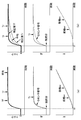
- FIG. 10 is a time chart when slip does not occur during deceleration on a high ⁇ flat road.
- FIG. 10A shows a comparative example when the torque sudden change distribution process is not performed
- FIG. 10B shows Example 1 when the torque sudden change distribution process is performed.
- the front / rear wheel torque distribution ratio St is set to 1: 1
- the accelerator pedal is released from a state where the vehicle is traveling on a flat road at a predetermined high vehicle speed
- the vehicle is decelerated at a deceleration corresponding to a predetermined coast torque.
- An example is shown.
- the regenerative torque of the front motor 1f and the rear motor 1r is generated to satisfy the required deceleration, and the vehicle is decelerated.
- FIG. 11 is a time chart when a slip occurs during deceleration on a flat road having a low ⁇ .
- FIG. 11A shows a comparative example in which the distribution process at the time of sudden torque change is not performed
- FIG. 11B shows the first embodiment when the distribution process at the time of sudden torque change is performed.
- Tf, Tr torque commands
- the average torque of the front and rear wheels also increases in accordance with Tf and Tr.
- both the first cutoff frequency ⁇ c1 and the second cutoff frequency ⁇ c2 are small values, so that the response of the Tr is corrected so as to be delayed.
- the deceleration that is reduced by the correction is added to Tf. Therefore, Tr and Tf have different values while satisfying the required deceleration. Since the absolute value of Tr is smaller than the absolute value of Tf, braking slip first occurs on the front wheels, and Tf is output after slip control. However, since no braking slip occurs on the rear wheel, the absolute value of Tr is large and the torque does not decrease. Therefore, it is possible to prevent a large drop in deceleration.
- the vehicle can be stabilized by the tire lateral force on the rear wheels. Thereafter, the absolute value of Tr also rises, and when slip occurs in the rear wheel, Tf has returned to some extent, and it is possible to avoid the rear wheel from undergoing a large braking slip. Therefore, it is possible to smoothly decelerate by suppressing the loss of deceleration compared to the comparative example. Further, by avoiding the front and rear wheels from slipping at the same time, the vehicle can be stabilized by securing the tire lateral force, and an excessive decrease in road surface ⁇ can be avoided.
- Example 1 has the following operational effects.
- a control device for an electric vehicle having a front motor 1f (front electric motor) that outputs torque to the front wheels of the vehicle and a rear motor 1r (rear electric motor) that outputs torque to the rear wheels of the vehicle, Torque distribution unit 105 (target torque calculation unit) that calculates a reference front motor torque command value Ttf and a reference rear motor torque command value Ttr (also referred to as a reference motor torque command value Ttfr) that are target torques of the front motor 1f and the rear motor 1r ), A final torque limiting unit 109 (torque command unit) that outputs a final torque command value Tt3 to the front motor 1f and the rear motor 1r, and a final torque command value with respect to the reference motor torque command value Ttfr in one of the front motor 1f and the rear motor 1r A torque sudden change distribution unit 500 (control unit) that controls the achievement rate of Tt3 to be lower than the other achievement rate.
- the difference between the response on the front wheel side and the response on the rear wheel side when the accelerator pedal opening speed ⁇ APO is small is small.
- the difference between the response on the front wheel side and the response on the rear wheel side when the accelerator pedal opening speed ⁇ APO is large is large. Therefore, it is possible to suppress the front and rear wheels from simultaneously driving slip or braking slip.
- the torque sudden change distribution unit 500 compensates for the torque that decreases by reducing the achievement rate of one of the other. Therefore, even when the actual torque on the rear wheel side decreases during deceleration, the required torque Tt can be secured by compensating on the front wheel side.
- the sudden torque change distribution unit 500 determines the achievement rate of one of the vehicles when the vehicle is at a predetermined vehicle speed or more and the reference motor torque command value Ttfr) is negative indicating deceleration. make low. Therefore, simultaneous locking of the front and rear wheels can be suppressed during deceleration at a predetermined vehicle speed or higher, and vehicle stability can be ensured.
- the torque sudden change distribution unit 500 does not compensate for the torque that is reduced by lowering one achievement rate on the other.
- the torque sudden change distribution unit 500 reduces the achievement rate of one when the vehicle is less than a predetermined vehicle speed and the road surface vertical gradient SP is equal to or greater than a predetermined value, as compared to the other cases. That is, when starting on an uphill road or the like, even if the actual torque is slightly lower than the required torque Tt, it is difficult for the driver to feel uncomfortable. For example, when the front and rear wheels slip simultaneously after starting on a snowy road, the snow on the surface melts due to the slip, and the road surface ⁇ may further decrease. In addition, the post-slip control Tf, Tr corrected to suppress this slip becomes very small, and the small post-slip control Tf, Tr is output at the same time.
- the achievement rate of one of the vehicles is reduced compared to the other cases, thereby suppressing the simultaneous slip of the front and rear wheels.
- a stable running state can be achieved.
- the sudden torque change distribution unit 500 lowers one achievement rate when the vehicle starts or decelerates when the road surface vertical gradient SP is equal to or greater than a predetermined value. Therefore, it is possible to achieve a stable traveling state while suppressing the simultaneous slip of the front and rear wheels.
- One is the rear motor 1r. Since the stability related to the yaw moment of the vehicle has a high correlation with the tire lateral force on the rear wheel side, the stability of the vehicle can be ensured by delaying the torque response on the rear wheel side.
- the torque response on the rear wheel side is delayed by appropriately setting the cutoff frequency of the low-pass filter processing.
- the torque response on the rear wheel side may be delayed by other methods.
- the torque command output timing to the rear wheels may be delayed using a timer or the like, or the response may be delayed by limiting the change of the torque command value by limiter processing, and there is no particular limitation.
- a control device for an electric vehicle having a front electric motor that outputs torque to the front wheels of the vehicle and a rear electric motor that outputs torque to the rear wheels of the vehicle has a torque command value for the front electric motor and the rear electric motor. While the torque command value to be output and the torque command value are changing, the front electric motor torque command value and the rear electric motor torque command value are larger than a predetermined value so that the difference between And a control unit for controlling the electric motor and the rear electric motor.
- the control unit increases the difference as the road surface gradient increases.
- the control unit includes a calculation unit that calculates a reference torque command value based on a preset reference torque distribution ratio between the front electric motor and the rear electric motor. After the change amount of the torque command value becomes less than a predetermined value, the torque command value is gradually returned to the reference torque command value.
- the control unit includes a calculation unit that calculates a reference torque command value based on a preset reference torque distribution ratio between the front electric motor and the rear electric motor. Increases the difference by changing the reference torque distribution ratio.
- the control unit controls the front electric motor and the rear electric motor so that the difference is not more than a preset value.
- the control unit is configured so that the torque command value of the rear electric motor is smaller than the torque command value of the front electric motor. Control the electric motor.
- a control device for an electric vehicle having a front electric motor that outputs torque to the front wheels of the vehicle and a rear electric motor that outputs torque to the rear wheels of the vehicle has a large longitudinal gradient of the road surface.
- the control unit controls the front electric motor and the rear electric motor so as to increase the difference between the torque command value of the front electric motor and the torque command value of the rear electric motor.
- the control unit controls the front electric motor and the rear electric motor so that the difference becomes larger than a predetermined value while the torque command value is changing.
- control unit may change the torque command value to the front electric motor and the rear electric motor after the change amount of the torque command value is less than a predetermined value. Are gradually returned toward the reference torque command value based on the preset reference torque distribution ratio.
- a control method for an electric vehicle having a front electric motor that outputs torque to the front wheels of the vehicle and a rear electric motor that outputs torque to the rear wheels of the vehicle includes the front electric motor and the A torque command step for outputting a torque command value to the rear electric motor, and a difference between the torque command value of the front electric motor and the torque command value of the rear electric motor is a predetermined value while the torque command value is changing. And a control step for controlling the front electric motor and the rear electric motor so as to be larger.
- the control step includes a step of increasing the difference as the road surface longitudinal gradient increases.
- control step includes a calculation step of calculating a reference torque command value based on a preset reference torque distribution ratio between the front electric motor and the rear electric motor. And a step of gradually returning the torque command value to the reference torque command value after the change amount of the torque command value becomes less than a predetermined value.
- control step includes a calculation step of calculating a reference torque command value based on a preset reference torque distribution ratio between the front electric motor and the rear electric motor. Comprises a step of increasing the difference by changing the reference torque distribution ratio.
- control step includes a step of controlling the front electric motor and the rear electric motor so that the difference is equal to or less than a predetermined value set in advance.
- control step includes the front electric motor and the rear electric motor so that the torque command value of the rear electric motor is smaller than the torque command value of the front electric motor. The step of controlling the electric motor is provided.
- an electric vehicle control system in another aspect, includes a front electric motor that outputs torque to the front wheels of the vehicle, a rear electric motor that outputs torque to the rear wheels of the vehicle, the front electric motor, and the rear electric motor.
- a control unit that controls a motor, and the control unit outputs a torque command value to the front electric motor and the rear electric motor, and while the torque command value is changing,
- a controller that controls the front electric motor and the rear electric motor so that a difference between a torque command value of the front electric motor and a torque command value of the rear electric motor is greater than a predetermined value.
- the control unit increases the difference as the road surface gradient increases.
- control unit includes a calculation unit that calculates a reference torque command value based on a preset reference torque distribution ratio between the front electric motor and the rear electric motor. After the change amount of the torque command value becomes less than a predetermined value, the torque command value is gradually returned to the reference torque command value.
Abstract
L'invention concerne un dispositif de commande pour un véhicule électrique grâce auquel il est possible d'empêcher tout glissement simultané des roues avant et arrière. Ce dispositif de commande pour un véhicule électrique commande un moteur électrique avant et un moteur électrique arrière de telle sorte qu'une différence entre une valeur de commande de couple du moteur électrique avant et une valeur de commande de couple d'un moteur électrique arrière devient supérieure à une valeur prédéterminée.
Priority Applications (3)
| Application Number | Priority Date | Filing Date | Title |
|---|---|---|---|
| EP17878414.6A EP3549810A4 (fr) | 2016-12-05 | 2017-11-28 | Dispositif de commande pour véhicule électrique, système de commande pour véhicule électrique, et procédé de commande pour véhicule électrique |
| US16/466,583 US11186283B2 (en) | 2016-12-05 | 2017-11-28 | Control apparatus for electric vehicle, control system for electric vehicle, and control method for electric vehicle |
| CN201780073796.5A CN110167785B (zh) | 2016-12-05 | 2017-11-28 | 电动车辆的控制装置、控制系统及控制方法 |
Applications Claiming Priority (2)
| Application Number | Priority Date | Filing Date | Title |
|---|---|---|---|
| JP2016-236037 | 2016-12-05 | ||
| JP2016236037A JP6993044B2 (ja) | 2016-12-05 | 2016-12-05 | 電動車両の制御装置、電動車両の制御システム及び電動車両の制御方法 |
Publications (1)
| Publication Number | Publication Date |
|---|---|
| WO2018105435A1 true WO2018105435A1 (fr) | 2018-06-14 |
Family
ID=62491955
Family Applications (1)
| Application Number | Title | Priority Date | Filing Date |
|---|---|---|---|
| PCT/JP2017/042478 WO2018105435A1 (fr) | 2016-12-05 | 2017-11-28 | Dispositif de commande pour véhicule électrique, système de commande pour véhicule électrique, et procédé de commande pour véhicule électrique |
Country Status (5)
| Country | Link |
|---|---|
| US (1) | US11186283B2 (fr) |
| EP (1) | EP3549810A4 (fr) |
| JP (1) | JP6993044B2 (fr) |
| CN (1) | CN110167785B (fr) |
| WO (1) | WO2018105435A1 (fr) |
Cited By (1)
| Publication number | Priority date | Publication date | Assignee | Title |
|---|---|---|---|---|
| US11220267B2 (en) * | 2020-01-06 | 2022-01-11 | Jtekt Corporation | Vehicle control device and four-wheel drive vehicle |
Families Citing this family (3)
| Publication number | Priority date | Publication date | Assignee | Title |
|---|---|---|---|---|
| KR102347651B1 (ko) * | 2017-12-11 | 2022-01-06 | 현대자동차주식회사 | 산악 도로 적응형 샤시통합제어 방법 및 차량 |
| KR20220048144A (ko) * | 2020-10-12 | 2022-04-19 | 현대자동차주식회사 | 차량의 구동력 제어 방법 |
| WO2022091272A1 (fr) * | 2020-10-28 | 2022-05-05 | 日産自動車株式会社 | Procédé de commande d'un véhicule électrique et système de commande d'un véhicule électrique |
Citations (7)
| Publication number | Priority date | Publication date | Assignee | Title |
|---|---|---|---|---|
| JPH0567444B2 (fr) * | 1985-09-09 | 1993-09-24 | Mazda Motor | |
| JPH09240301A (ja) * | 1996-03-11 | 1997-09-16 | Nissan Motor Co Ltd | 車両の車輪駆動力配分制御装置 |
| JP2001171378A (ja) * | 1999-10-08 | 2001-06-26 | Toyota Motor Corp | 4輪駆動車の制御装置 |
| JP2005184944A (ja) | 2003-12-18 | 2005-07-07 | Hitachi Ltd | 車両用制御装置及び車両用制御方法 |
| JP2006248319A (ja) * | 2005-03-09 | 2006-09-21 | Toyota Motor Corp | 自動車およびその制御方法 |
| JP2007210418A (ja) * | 2006-02-08 | 2007-08-23 | Toyota Motor Corp | 車両の制御装置 |
| JP2016093033A (ja) * | 2014-11-07 | 2016-05-23 | トヨタ自動車株式会社 | 自動車 |
Family Cites Families (6)
| Publication number | Priority date | Publication date | Assignee | Title |
|---|---|---|---|---|
| JP2001105919A (ja) * | 1999-10-08 | 2001-04-17 | Toyota Motor Corp | 前後輪駆動車両の制御装置 |
| FR2799417B1 (fr) * | 1999-10-08 | 2009-01-23 | Toyota Motor Co Ltd | Dispositif de controle de vehicule, notamment pour la repartition des forces de traction avant-arriere |
| JP4379406B2 (ja) | 2005-03-04 | 2009-12-09 | 日産自動車株式会社 | 車両の駆動力配分制御装置 |
| JP4696918B2 (ja) * | 2006-01-10 | 2011-06-08 | トヨタ自動車株式会社 | 車両の制御装置 |
| US8965609B2 (en) * | 2011-12-29 | 2015-02-24 | Kawasaki Jukogyo Kabushiki Kaisha | Electric vehicle |
| US9469199B1 (en) | 2015-05-28 | 2016-10-18 | Atieva, Inc. | Dual data rate traction control system for a four wheel drive electric vehicle |
-
2016
- 2016-12-05 JP JP2016236037A patent/JP6993044B2/ja active Active
-
2017
- 2017-11-28 US US16/466,583 patent/US11186283B2/en active Active
- 2017-11-28 WO PCT/JP2017/042478 patent/WO2018105435A1/fr active Application Filing
- 2017-11-28 CN CN201780073796.5A patent/CN110167785B/zh active Active
- 2017-11-28 EP EP17878414.6A patent/EP3549810A4/fr active Pending
Patent Citations (7)
| Publication number | Priority date | Publication date | Assignee | Title |
|---|---|---|---|---|
| JPH0567444B2 (fr) * | 1985-09-09 | 1993-09-24 | Mazda Motor | |
| JPH09240301A (ja) * | 1996-03-11 | 1997-09-16 | Nissan Motor Co Ltd | 車両の車輪駆動力配分制御装置 |
| JP2001171378A (ja) * | 1999-10-08 | 2001-06-26 | Toyota Motor Corp | 4輪駆動車の制御装置 |
| JP2005184944A (ja) | 2003-12-18 | 2005-07-07 | Hitachi Ltd | 車両用制御装置及び車両用制御方法 |
| JP2006248319A (ja) * | 2005-03-09 | 2006-09-21 | Toyota Motor Corp | 自動車およびその制御方法 |
| JP2007210418A (ja) * | 2006-02-08 | 2007-08-23 | Toyota Motor Corp | 車両の制御装置 |
| JP2016093033A (ja) * | 2014-11-07 | 2016-05-23 | トヨタ自動車株式会社 | 自動車 |
Non-Patent Citations (1)
| Title |
|---|
| See also references of EP3549810A4 |
Cited By (1)
| Publication number | Priority date | Publication date | Assignee | Title |
|---|---|---|---|---|
| US11220267B2 (en) * | 2020-01-06 | 2022-01-11 | Jtekt Corporation | Vehicle control device and four-wheel drive vehicle |
Also Published As
| Publication number | Publication date |
|---|---|
| EP3549810A1 (fr) | 2019-10-09 |
| CN110167785B (zh) | 2022-10-11 |
| CN110167785A (zh) | 2019-08-23 |
| US11186283B2 (en) | 2021-11-30 |
| EP3549810A4 (fr) | 2019-11-13 |
| US20200070836A1 (en) | 2020-03-05 |
| JP2018093646A (ja) | 2018-06-14 |
| JP6993044B2 (ja) | 2022-01-13 |
Similar Documents
| Publication | Publication Date | Title |
|---|---|---|
| WO2018105507A1 (fr) | Dispositif de commande pour véhicule électrique, système de commande pour véhicule électrique, et procédé de commande pour véhicule électrique | |
| JP6847492B2 (ja) | 電動車両の制御装置、電動車両の制御システム及び電動車両の制御方法 | |
| JP4636062B2 (ja) | 車両の挙動制御装置 | |
| KR101697809B1 (ko) | 브레이킹 및 드라이빙 동작들로 드라이빙 역학에 영향을 미치는 방법 및 브레이킹 시스템 | |
| WO2018105435A1 (fr) | Dispositif de commande pour véhicule électrique, système de commande pour véhicule électrique, et procédé de commande pour véhicule électrique | |
| US20140200787A1 (en) | Vehicle Dynamics Control Device | |
| JP5999047B2 (ja) | 車両制御装置 | |
| US8543300B2 (en) | Vehicle behavior control apparatus | |
| JP6213020B2 (ja) | 車両制御装置 | |
| US20160264002A1 (en) | Braking force control method for vehicle | |
| JP4582031B2 (ja) | 四輪駆動車の駆動力制御装置 | |
| KR20210071133A (ko) | 차량의 자세 제어 방법 | |
| EP3529113B1 (fr) | Commande dynamique latérale pour mélange de frein à récupération et à friction | |
| WO2018051704A1 (fr) | Dispositif de commande, système de commande et procédé de commande de véhicule électrique | |
| JP4114065B2 (ja) | 四輪駆動車の挙動制御装置 | |
| JP2016190607A (ja) | 車両の制御装置 | |
| JP4784741B2 (ja) | 車輌の駆動力制御装置 | |
| KR20050053126A (ko) | 구동력을 이용한 차량 자세 제어 시스템 및 방법 | |
| JP2000203313A (ja) | 駆動滑り制御方法および装置 | |
| KR20150078537A (ko) | 인텔리전트 타이어를 이용한 인휠 시스템 차량의 제어방법 |
Legal Events
| Date | Code | Title | Description |
|---|---|---|---|
| 121 | Ep: the epo has been informed by wipo that ep was designated in this application |
Ref document number: 17878414 Country of ref document: EP Kind code of ref document: A1 |
|
| NENP | Non-entry into the national phase |
Ref country code: DE |
|
| WWE | Wipo information: entry into national phase |
Ref document number: 2017878414 Country of ref document: EP |