WO2018105435A1 - Control device for electric vehicle, control system for electric vehicle, and control method for electric vehicle - Google Patents
Control device for electric vehicle, control system for electric vehicle, and control method for electric vehicle Download PDFInfo
- Publication number
- WO2018105435A1 WO2018105435A1 PCT/JP2017/042478 JP2017042478W WO2018105435A1 WO 2018105435 A1 WO2018105435 A1 WO 2018105435A1 JP 2017042478 W JP2017042478 W JP 2017042478W WO 2018105435 A1 WO2018105435 A1 WO 2018105435A1
- Authority
- WO
- WIPO (PCT)
- Prior art keywords
- electric motor
- torque
- command value
- torque command
- control
- Prior art date
Links
Images


Classifications
-
- B—PERFORMING OPERATIONS; TRANSPORTING
- B60—VEHICLES IN GENERAL
- B60L—PROPULSION OF ELECTRICALLY-PROPELLED VEHICLES; SUPPLYING ELECTRIC POWER FOR AUXILIARY EQUIPMENT OF ELECTRICALLY-PROPELLED VEHICLES; ELECTRODYNAMIC BRAKE SYSTEMS FOR VEHICLES IN GENERAL; MAGNETIC SUSPENSION OR LEVITATION FOR VEHICLES; MONITORING OPERATING VARIABLES OF ELECTRICALLY-PROPELLED VEHICLES; ELECTRIC SAFETY DEVICES FOR ELECTRICALLY-PROPELLED VEHICLES
- B60L15/00—Methods, circuits, or devices for controlling the traction-motor speed of electrically-propelled vehicles
- B60L15/20—Methods, circuits, or devices for controlling the traction-motor speed of electrically-propelled vehicles for control of the vehicle or its driving motor to achieve a desired performance, e.g. speed, torque, programmed variation of speed
-
- B—PERFORMING OPERATIONS; TRANSPORTING
- B60—VEHICLES IN GENERAL
- B60W—CONJOINT CONTROL OF VEHICLE SUB-UNITS OF DIFFERENT TYPE OR DIFFERENT FUNCTION; CONTROL SYSTEMS SPECIALLY ADAPTED FOR HYBRID VEHICLES; ROAD VEHICLE DRIVE CONTROL SYSTEMS FOR PURPOSES NOT RELATED TO THE CONTROL OF A PARTICULAR SUB-UNIT
- B60W30/00—Purposes of road vehicle drive control systems not related to the control of a particular sub-unit, e.g. of systems using conjoint control of vehicle sub-units, or advanced driver assistance systems for ensuring comfort, stability and safety or drive control systems for propelling or retarding the vehicle
- B60W30/18—Propelling the vehicle
- B60W30/18172—Preventing, or responsive to skidding of wheels
-
- B—PERFORMING OPERATIONS; TRANSPORTING
- B60—VEHICLES IN GENERAL
- B60L—PROPULSION OF ELECTRICALLY-PROPELLED VEHICLES; SUPPLYING ELECTRIC POWER FOR AUXILIARY EQUIPMENT OF ELECTRICALLY-PROPELLED VEHICLES; ELECTRODYNAMIC BRAKE SYSTEMS FOR VEHICLES IN GENERAL; MAGNETIC SUSPENSION OR LEVITATION FOR VEHICLES; MONITORING OPERATING VARIABLES OF ELECTRICALLY-PROPELLED VEHICLES; ELECTRIC SAFETY DEVICES FOR ELECTRICALLY-PROPELLED VEHICLES
- B60L15/00—Methods, circuits, or devices for controlling the traction-motor speed of electrically-propelled vehicles
- B60L15/20—Methods, circuits, or devices for controlling the traction-motor speed of electrically-propelled vehicles for control of the vehicle or its driving motor to achieve a desired performance, e.g. speed, torque, programmed variation of speed
- B60L15/2009—Methods, circuits, or devices for controlling the traction-motor speed of electrically-propelled vehicles for control of the vehicle or its driving motor to achieve a desired performance, e.g. speed, torque, programmed variation of speed for braking
-
- B—PERFORMING OPERATIONS; TRANSPORTING
- B60—VEHICLES IN GENERAL
- B60L—PROPULSION OF ELECTRICALLY-PROPELLED VEHICLES; SUPPLYING ELECTRIC POWER FOR AUXILIARY EQUIPMENT OF ELECTRICALLY-PROPELLED VEHICLES; ELECTRODYNAMIC BRAKE SYSTEMS FOR VEHICLES IN GENERAL; MAGNETIC SUSPENSION OR LEVITATION FOR VEHICLES; MONITORING OPERATING VARIABLES OF ELECTRICALLY-PROPELLED VEHICLES; ELECTRIC SAFETY DEVICES FOR ELECTRICALLY-PROPELLED VEHICLES
- B60L3/00—Electric devices on electrically-propelled vehicles for safety purposes; Monitoring operating variables, e.g. speed, deceleration or energy consumption
- B60L3/10—Indicating wheel slip ; Correction of wheel slip
- B60L3/106—Indicating wheel slip ; Correction of wheel slip for maintaining or recovering the adhesion of the drive wheels
-
- B—PERFORMING OPERATIONS; TRANSPORTING
- B60—VEHICLES IN GENERAL
- B60W—CONJOINT CONTROL OF VEHICLE SUB-UNITS OF DIFFERENT TYPE OR DIFFERENT FUNCTION; CONTROL SYSTEMS SPECIALLY ADAPTED FOR HYBRID VEHICLES; ROAD VEHICLE DRIVE CONTROL SYSTEMS FOR PURPOSES NOT RELATED TO THE CONTROL OF A PARTICULAR SUB-UNIT
- B60W10/00—Conjoint control of vehicle sub-units of different type or different function
- B60W10/04—Conjoint control of vehicle sub-units of different type or different function including control of propulsion units
- B60W10/08—Conjoint control of vehicle sub-units of different type or different function including control of propulsion units including control of electric propulsion units, e.g. motors or generators
-
- B—PERFORMING OPERATIONS; TRANSPORTING
- B60—VEHICLES IN GENERAL
- B60W—CONJOINT CONTROL OF VEHICLE SUB-UNITS OF DIFFERENT TYPE OR DIFFERENT FUNCTION; CONTROL SYSTEMS SPECIALLY ADAPTED FOR HYBRID VEHICLES; ROAD VEHICLE DRIVE CONTROL SYSTEMS FOR PURPOSES NOT RELATED TO THE CONTROL OF A PARTICULAR SUB-UNIT
- B60W40/00—Estimation or calculation of non-directly measurable driving parameters for road vehicle drive control systems not related to the control of a particular sub unit, e.g. by using mathematical models
- B60W40/02—Estimation or calculation of non-directly measurable driving parameters for road vehicle drive control systems not related to the control of a particular sub unit, e.g. by using mathematical models related to ambient conditions
- B60W40/06—Road conditions
- B60W40/064—Degree of grip
-
- B—PERFORMING OPERATIONS; TRANSPORTING
- B60—VEHICLES IN GENERAL
- B60L—PROPULSION OF ELECTRICALLY-PROPELLED VEHICLES; SUPPLYING ELECTRIC POWER FOR AUXILIARY EQUIPMENT OF ELECTRICALLY-PROPELLED VEHICLES; ELECTRODYNAMIC BRAKE SYSTEMS FOR VEHICLES IN GENERAL; MAGNETIC SUSPENSION OR LEVITATION FOR VEHICLES; MONITORING OPERATING VARIABLES OF ELECTRICALLY-PROPELLED VEHICLES; ELECTRIC SAFETY DEVICES FOR ELECTRICALLY-PROPELLED VEHICLES
- B60L2220/00—Electrical machine types; Structures or applications thereof
- B60L2220/40—Electrical machine applications
- B60L2220/42—Electrical machine applications with use of more than one motor
-
- B—PERFORMING OPERATIONS; TRANSPORTING
- B60—VEHICLES IN GENERAL
- B60W—CONJOINT CONTROL OF VEHICLE SUB-UNITS OF DIFFERENT TYPE OR DIFFERENT FUNCTION; CONTROL SYSTEMS SPECIALLY ADAPTED FOR HYBRID VEHICLES; ROAD VEHICLE DRIVE CONTROL SYSTEMS FOR PURPOSES NOT RELATED TO THE CONTROL OF A PARTICULAR SUB-UNIT
- B60W2520/00—Input parameters relating to overall vehicle dynamics
- B60W2520/26—Wheel slip
- B60W2520/263—Slip values between front and rear axle
-
- B—PERFORMING OPERATIONS; TRANSPORTING
- B60—VEHICLES IN GENERAL
- B60W—CONJOINT CONTROL OF VEHICLE SUB-UNITS OF DIFFERENT TYPE OR DIFFERENT FUNCTION; CONTROL SYSTEMS SPECIALLY ADAPTED FOR HYBRID VEHICLES; ROAD VEHICLE DRIVE CONTROL SYSTEMS FOR PURPOSES NOT RELATED TO THE CONTROL OF A PARTICULAR SUB-UNIT
- B60W2520/00—Input parameters relating to overall vehicle dynamics
- B60W2520/30—Wheel torque
-
- B—PERFORMING OPERATIONS; TRANSPORTING
- B60—VEHICLES IN GENERAL
- B60W—CONJOINT CONTROL OF VEHICLE SUB-UNITS OF DIFFERENT TYPE OR DIFFERENT FUNCTION; CONTROL SYSTEMS SPECIALLY ADAPTED FOR HYBRID VEHICLES; ROAD VEHICLE DRIVE CONTROL SYSTEMS FOR PURPOSES NOT RELATED TO THE CONTROL OF A PARTICULAR SUB-UNIT
- B60W2710/00—Output or target parameters relating to a particular sub-units
- B60W2710/08—Electric propulsion units
- B60W2710/083—Torque
- B60W2710/085—Torque change rate
-
- B—PERFORMING OPERATIONS; TRANSPORTING
- B60—VEHICLES IN GENERAL
- B60W—CONJOINT CONTROL OF VEHICLE SUB-UNITS OF DIFFERENT TYPE OR DIFFERENT FUNCTION; CONTROL SYSTEMS SPECIALLY ADAPTED FOR HYBRID VEHICLES; ROAD VEHICLE DRIVE CONTROL SYSTEMS FOR PURPOSES NOT RELATED TO THE CONTROL OF A PARTICULAR SUB-UNIT
- B60W2720/00—Output or target parameters relating to overall vehicle dynamics
- B60W2720/40—Torque distribution
- B60W2720/403—Torque distribution between front and rear axle
-
- Y—GENERAL TAGGING OF NEW TECHNOLOGICAL DEVELOPMENTS; GENERAL TAGGING OF CROSS-SECTIONAL TECHNOLOGIES SPANNING OVER SEVERAL SECTIONS OF THE IPC; TECHNICAL SUBJECTS COVERED BY FORMER USPC CROSS-REFERENCE ART COLLECTIONS [XRACs] AND DIGESTS
- Y02—TECHNOLOGIES OR APPLICATIONS FOR MITIGATION OR ADAPTATION AGAINST CLIMATE CHANGE
- Y02T—CLIMATE CHANGE MITIGATION TECHNOLOGIES RELATED TO TRANSPORTATION
- Y02T10/00—Road transport of goods or passengers
- Y02T10/60—Other road transportation technologies with climate change mitigation effect
- Y02T10/64—Electric machine technologies in electromobility
-
- Y—GENERAL TAGGING OF NEW TECHNOLOGICAL DEVELOPMENTS; GENERAL TAGGING OF CROSS-SECTIONAL TECHNOLOGIES SPANNING OVER SEVERAL SECTIONS OF THE IPC; TECHNICAL SUBJECTS COVERED BY FORMER USPC CROSS-REFERENCE ART COLLECTIONS [XRACs] AND DIGESTS
- Y02—TECHNOLOGIES OR APPLICATIONS FOR MITIGATION OR ADAPTATION AGAINST CLIMATE CHANGE
- Y02T—CLIMATE CHANGE MITIGATION TECHNOLOGIES RELATED TO TRANSPORTATION
- Y02T10/00—Road transport of goods or passengers
- Y02T10/60—Other road transportation technologies with climate change mitigation effect
- Y02T10/72—Electric energy management in electromobility
Definitions
- the present invention relates to an electric vehicle control device, a control system, and a control method.
- the objective of this invention is providing the control apparatus of the electric vehicle which can suppress that a front-and-rear wheel slips simultaneously.
- the control device for an electric vehicle includes a front electric motor and a rear electric motor so that a difference between a torque command value of the front electric motor and a torque command value of the rear electric motor is larger than a predetermined value. Control.
- FIG. 1 is a system diagram of an electric vehicle according to a first embodiment.
- FIG. 2 is a control block diagram of the electric vehicle according to the first embodiment. It is a control block diagram showing the detail of the distribution part at the time of acceleration / deceleration of Example 1.
- FIG. It is a time chart when a slip does not occur when starting on a high ⁇ uphill road. It is a time chart when a slip occurs when starting on a low ⁇ uphill road.
- FIG. 6 is a control block diagram of an electric vehicle according to a second embodiment. It is a control block diagram showing the detail of the torque sudden change distribution part of Example 2.
- FIG. It is a time chart when a slip does not occur when starting on a high ⁇ uphill road.
- FIG. 1 is a system diagram of the electric vehicle according to the first embodiment.
- the electric vehicle according to the first embodiment is a four-wheel drive vehicle in which front wheels FL and FR are driven by a front motor 1f, and rear wheels RL and RR are driven by a rear motor 1r.
- a differential gear 3f is connected to the front motor 1f via a speed reduction mechanism 2f.
- a drive shaft 4f is connected to the differential gear 3f.
- Front wheels FL and FR are connected to the drive shaft 4f.
- the inverter 5f has a motor control unit MCUf that controls the front motor 1f.
- a differential gear 3r is connected to the rear motor 1r via a speed reduction mechanism 2r.
- a drive shaft 4r is connected to the differential gear 3r.
- Rear wheels RL and RR are connected to the drive shaft 4r.
- the inverter 5r has a motor control unit MCUr that controls the rear motor 1r.
- the high voltage battery BAT has a battery control unit BCU that controls supply power.
- the high voltage battery BAT is a battery module in which a plurality of batteries are connected, and the battery control unit BCU controls the power supplied from one battery module to a plurality of motors (front motor 1f and rear motor 1r).
- the electric vehicle includes a stroke sensor 6 that outputs a brake pedal stroke signal, an accelerator opening sensor 7 that outputs an accelerator opening signal, and resolvers 8f and 8r that output a motor rotation speed signal including the rotation direction of the electric motor 1.
- a longitudinal acceleration sensor 12 for detecting the longitudinal acceleration sg of the vehicle.
- the vehicle control unit CU receives a range position signal from the shift lever, a brake pedal stroke signal from the stroke sensor 6, and an accelerator opening signal from the accelerator opening sensor 7. Further, the vehicle control unit CU receives the motor rotation speed signals from the resolvers 8f and 8r via the motor control units MCUf and MCUr.
- the vehicle control unit CU calculates a drive torque command value of the electric motor 1 based on the accelerator opening and the like, and drives the front motor 1f and the rear motor 1r according to the drive torque command value.
- the brake controller 9 is connected to wheel speed sensors 10FL, 10FR, 10RL, 10RR (hereinafter also simply referred to as 10) provided on each wheel, and receives a rotation speed signal of each wheel.
- the wheel speed sensor 10 detects the wheel speed from the period of the electromagnetic pulse.
- the brake controller 9 adjusts the brake fluid supplied to the brake unit by the hydraulic pressure of each wheel based on the amount of brake operation of the driver detected by the stroke sensor 6, and controls the braking torque of each wheel.
- Information communication between the motor control units MCUf and MCUr, the vehicle control unit CU, and the brake controller 9 is performed via the CAN communication line 11.
- FIG. 2 is a control block diagram of the electric vehicle according to the first embodiment.
- the driver request torque calculation unit 101 calculates the driver request torque Td based on the accelerator opening APO and the vehicle speed VSP.
- the driver request torque Td is set to a larger value as the accelerator opening APO is higher.
- the regenerative torque receiving unit 102 receives the required regenerative torque Trg based on the required braking torque calculated by the other calculation units, and corrects the driver required torque Td.
- the required torque receiving unit 103 receives the required drive torque Tof calculated by the other calculation units and corrects the driver required torque Td.
- the total shaft torque command value of the front motor 1f and the rear motor 1r obtained from the command values of the driver request torque calculation unit 101, the regenerative torque reception unit 102, and the request torque reception unit 103 is output as the vehicle request torque Tt. .
- the distribution ratio arbitration unit 104 determines a distribution ratio St for distributing the required torque Tt to the front motor 1f and the rear motor 1r based on the driving force distribution ratio command Std and the regenerative braking force distribution ratio command Strg.
- the driving force distribution ratio command is a command that is output by calculating a driving force distribution ratio between the front wheels and the rear wheels in accordance with the running state in a driving force distribution ratio calculation unit (not shown).
- the regenerative braking force distribution ratio command is a command output by calculating a regenerative braking force distribution ratio between the front wheels and the rear wheels in a regenerative braking force distribution ratio calculation unit (not shown).
- the distribution ratio arbitration unit 104 determines the distribution ratio St based on each distribution ratio and the current running state.
- the torque distribution unit 105 calculates a reference front motor torque command value Ttf and a reference rear motor torque command value Ttr based on the required torque Tt and the distribution ratio St.
- the front motor 1f and the rear motor 1r are collectively referred to as a reference motor torque command value Ttfr.
- This reference motor torque command value Ttfr corresponds to a target torque for controlling the front motor 1f and the rear motor 1r.
- Acceleration / deceleration distribution unit 600 is based on accelerator pedal opening APO, brake pedal stroke BPS, reference front motor torque command value Ttf, reference rear motor torque command value Ttry, and longitudinal gradient SP.
- the distribution ratio St is changed, and the acceleration / deceleration reference front motor torque command value Ttfy and the acceleration / deceleration reference rear motor torque command value Ttry (hereinafter collectively referred to as acceleration / deceleration reference motor torque command value Ttfry) Is calculated.
- acceleration / deceleration reference motor torque command value Ttfry acceleration / deceleration reference motor torque command value Ttfry
- the torque limiter 106 uses positive torque limit values Tplimf, Tplimr and negative torque limit values Tnlimf, Tnlimr (hereinafter, these limit values are referred to as torque limit values Tlim) selected by a torque limit value selection unit 205 described later.
- torque limit values Tlim positive torque limit values selected by a torque limit value selection unit 205 described later.
- the limited first front motor torque command value Ttf1 and the first rear motor torque command value Ttr1 (hereinafter, these command values are referred to as the first torque command value Tt1) are calculated.
- the acceleration / deceleration reference motor torque command value Ttfry is corrected to be within the torque limit value Tlim.
- the torque redistribution unit 107 when the sum of the first torque command values Tt1 of the respective motors is less than the required torque Tt, the first torque of each motor is changed to a motor whose first torque command value Tt1 is lower than the torque limit value Tlim.
- a second front motor torque command value Ttf2 obtained by redistributing the torque within a range where the total of the command values Tt1 does not exceed the required torque Tt, and a second rear motor torque command value Ttr2 (hereinafter, these command values are referred to as a second torque command value Tt2). Is calculated).
- the slip control unit 108 determines whether or not a slip has occurred on the wheel based on the wheel speed sv, the longitudinal acceleration sg, and torque command values of the temperature protection units 302f and 302r, which will be described later. When the braking slip is included), the torque limit amount to the motor torque connected to the wheel where the slip occurs is calculated.
- the final torque limiting unit 109 outputs the final torque command value Tt3 determined based on the torque limit calculated by the slip control unit 108 to the motors 1f and 1r with respect to the second torque command value Tt2.
- the positive torque limit values Tplimtf and Tplimtr and the negative torque limit values Tnlimtf and Tnlimtr are also referred to as maximum torque limit value Tlimax. This is because a torque characteristic with respect to the rotational speed of the motor is determined in advance, and a torque value that can be output to a maximum at a certain rotational speed is set from a map or the like.
- the first power limit value Wlimf1 of the front motor 1f and the first power of the rear motor 1r are based on the battery power limit value Wlim that is the upper limit value of power supplied from the high-voltage battery BAT and the distribution ratio St.
- a power limit value Wlimr1 (hereinafter, Wlimf1 and Wlimr1 are also referred to as a first power limit value Wlim1) is calculated. That is, when power is supplied to a plurality of motors from one high-voltage battery BAT, if the power consumption of each motor is determined individually, the total power consumption may exceed the battery power limit value Wlim.
- the second power limit value Wlimf2 of the front motor 1f and the second power limit value Wlimr2 of the rear motor 1r (hereinafter, Wlimf2 and Wlimr2 are also referred to as the second power limit value Wlim2) are calculated.
- a positive torque limit value Tplimw and a negative torque limit value Tnlimw (hereinafter, referred to as the battery potential Vbat of the high voltage battery BAT, the rotational speeds Vmf and Vmr, and the second power limit value Wlim2). Tplimw and Tnlimw are also described as the first torque limit value Tlimw).
- the torque limit value selection unit 205 selects a lower limit value from the maximum torque limit value Tlimmax and the first torque limit value Tlimw, and outputs it as the torque limit value Tlim.
- the motor control units MCUf and MCUr include torque limiting units 301f and 301r, temperature protection units 302f and 302r, and vibration control units 303f and 303r.
- the torque limiters 301f and 301r calculate the motor torque command value based on the final torque command value Tt3 output from the final torque limiter 109 and the torque limit value Tlim output from the torque limit value selector 205.
- a motor torque command is issued so that the motor becomes a predetermined temperature or less from the calorific value calculated based on the current value supplied to the motor and the measured value of the temperature sensor attached to the motor. Limit the value.
- the damping control units 303f and 303r calculate damping torque that suppresses vibrations generated in the drive shafts 4f and 4r, give damping torque to the motor torque command value, and finally execute motor torque control.
- FIG. 3 is a control block diagram illustrating details of the acceleration / deceleration distribution unit according to the first embodiment.
- the torque distribution ratio limiter 601 calculates a torque distribution ratio limit value St (f) lim based on the longitudinal gradient SP.
- the torque distribution ratio limit value St (f) lim is a limit value of the front wheel distribution ratio St (f) distributed to the front wheels based on the distribution ratio St, and the front wheel: rear wheel distribution ratio St is 1: 1.
- St (f) is 50%, and in the case of 2: 1, St (f) is 67%.
- St (f) is decreased, and when the longitudinal gradient SP is large, St (f) lim is increased.
- the deviation calculating unit 602 subtracts St (f) from St (f) lim to calculate the insufficient distribution ratio (%) of the torque distributed to the front wheels.
- the distribution ratio selection unit 603 outputs the larger value of the shortage distribution ratio (%) and 0%. Therefore, when St (f) lim is larger than St (f), the shortage allocation ratio (%) is output as it is, and when St (f) lim is smaller than St (f), a large torque is already applied to the front wheels. Is output and 0% is output.
- the absolute value processing unit 604 converts the required torque Tt into an absolute value and outputs the absolute value to the below-described insufficient torque calculation unit 605.
- the insufficient torque calculation unit 605 multiplies the required torque absolute value
- the torque correction amount limit value calculation unit 606 sets a correction amount upper limit value Tfhlim of a first torque correction amount, which will be described later, based on the longitudinal gradient SP.
- Tfhlim is decreased, and as the longitudinal gradient is increased, Tfhlim is increased.
- Tfhlim is set to a constant value. That is, by restricting the first torque correction amount to some extent, excessive correction is suppressed, and an increase in the torque difference between the front and rear wheels is avoided more than necessary. Details will be described later.
- Accelerator pedal operation speed calculator 607 differentiates accelerator pedal opening APO or calculates accelerator pedal operation speed ⁇ APO, which is the APO change amount until the next control cycle.
- Accelerator-side low-pass filter 608 performs a low-pass filter process on ⁇ APO to calculate an accelerator pedal operation speed filtering value F ( ⁇ APO). This prevents ⁇ APO from being output as 0 even when the actual motor torque change does not catch up with the accelerator pedal operation.
- the accelerator side correction gain calculation unit 609 calculates the accelerator side correction gain K1 according to F ( ⁇ APO). When F ( ⁇ APO) is small, K1 is a small value, and when F ( ⁇ APO) is large, K1 is a large value. In other words, when the accelerator pedal operation speed ⁇ APO is low, K1 is set to 0 to return to the initial distribution ratio St, and when the accelerator pedal operation speed ⁇ APO is high, the distribution ratio St is allowed to change.
- the brake pedal operation speed calculation unit 610 differentiates the brake pedal stroke amount BPS or calculates the brake pedal operation speed ⁇ BSP, which is the BPS change amount until the next control cycle.
- the brake-side low-pass filter 611 performs a low-pass filter process on ⁇ BPS and calculates a brake pedal operation speed filtering value F ( ⁇ BPS). This prevents ⁇ BPS from being output as 0 even when the actual motor torque change does not catch up with the brake pedal operation.
- the brake side correction gain calculation unit 612 calculates a brake side correction gain K2 corresponding to F ( ⁇ BPS). When F ( ⁇ BPS) is small, K2 is a small value, and when F ( ⁇ BPS) is large, K2 is a large value. In other words, when the brake pedal operation speed ⁇ BPS is low, K2 is set to 0 to return to the initial distribution ratio St, and when the brake pedal operation speed ⁇ BPS is high, the distribution ratio St is allowed to change.
- the gain selection unit 613 selects a larger one of the accelerator side correction gain K1 and the brake side correction gain K2, and outputs the selected gain to the gain multiplication unit 614 described later.
- the gain multiplication unit 614 multiplies the insufficient torque calculated by the insufficient torque calculation unit 605 by the gain of K1 or K2, and calculates the insufficient torque when the torque changes.
- K1 and K2 are set to 0, so that insufficient torque is not output.
- the torque correction amount selection unit 615 applies the smaller torque of the correction amount upper limit value Tfhlim calculated by the torque correction amount limit value calculation unit 606 and the torque shortage insufficient torque calculated by the gain multiplication unit 614 to the smaller one. Output as 1 torque correction amount. Therefore, for example, even if the accelerator pedal is suddenly depressed on an uphill road and the insufficient torque at the time of a large torque change is calculated by correcting the distribution ratio St, a value not exceeding the correction amount upper limit value Tfhlim is output.
- the code extraction unit 616 extracts the sign of the required torque Tt and outputs it to the code multiplication unit 617 described later.
- the sign multiplier 617 multiplies the sign of the required torque Tt by the first torque correction amount to calculate the final torque correction amount.
- Acceleration / deceleration reference front motor torque command value calculation unit 618 adds a torque correction amount to reference front motor torque command value Ttf, and outputs an acceleration / deceleration reference front motor torque command value Ttfx.
- Acceleration / deceleration reference rear motor torque command value calculation unit 619 subtracts acceleration / deceleration reference front motor torque command value Ttfx from request torque Tt, and outputs acceleration / deceleration reference rear motor torque command value Ttrx. Therefore, even if the distribution ratio St is changed, the required torque Tt is not changed.
- FIG. 4 is a time chart when no slip occurs when starting on a high ⁇ uphill road.
- FIG. 4A shows a comparative example when the torque sudden change distribution process is not performed
- FIG. 4B shows Example 1 when the torque sudden change distribution process is performed.
- This time chart shows an example of starting from a state where the front and rear wheel torque distribution ratio St is 1: 1 and the vehicle is stopped on an uphill road. Therefore, in the stop state, the longitudinal acceleration sg of the longitudinal acceleration sensor 12 (hereinafter also referred to as G sensor) indicates a value offset by the amount corresponding to the slope.
- the front motor torque command value is described as Tf
- the rear motor torque command value is described as Tr.
- the front wheel speed is described as a front wheel sv
- the rear wheel speed is described as a rear wheel sv.
- the accelerator side correction gain K1 is set, and since it is an uphill road, the correction amount upper limit value Tfhlim corresponding to the longitudinal gradient SP is increased, and the front wheels The corrected torque distribution Tf is obtained by increasing the torque distribution to. At the same time, torque distribution to the rear wheels is suppressed, and the corrected Tr becomes small. Since the total torque of the corrected Tf and the corrected Tr matches the required torque Tt, the vehicle travels in the same manner as in the comparative example and does not give the driver a sense of incongruity.
- FIG. 5 is a time chart when a slip occurs when starting on a low ⁇ uphill road.
- FIG. 5A shows a comparative example when the torque sudden change distribution process is not performed
- FIG. 5B shows Example 1 when the torque sudden change distribution process is performed.
- Tf and Tr torque commands
- the average torque of the wheel also increases in accordance with Tf and Tr.
- Tf and Tr are corrected by slip control, and Tf and Tr are output after slip control. Therefore, after the slip control, Tf and Tr are greatly reduced, both the front wheel sv and the rear wheel sv are greatly reduced, and the longitudinal acceleration sg is also greatly reduced.
- the forward running state can be continued after the slip control.
- Tf and Tr after slip control corrected to suppress this slip are very small, and Tf and Tr after small slip control are output at the same time.
- the accelerator side correction gain K1 is set, and since it is an uphill road, the correction amount upper limit value Tfhlim corresponding to the longitudinal gradient SP increases, and the front wheels The corrected torque distribution Tf is obtained by increasing the torque distribution to. At the same time, torque distribution to the rear wheels is suppressed, and the corrected Tr becomes small.
- Tr does not greatly reduce the torque. Therefore, a large drop in the longitudinal acceleration sg can be prevented. Further, even if the tire lateral force is reduced due to the slip of the front wheel, the vehicle can be stabilized by the tire lateral force of the rear wheel. Thereafter, Tr also rises, and when slip occurs in the rear wheel, Tf has returned to some extent, and it is possible to avoid the rear wheel from slipping significantly. Therefore, although the average torque is slightly lower than the driver's required torque, the vehicle can start smoothly by preventing a large drop in the longitudinal acceleration sg compared to the comparative example.
- a control device for an electric vehicle having a front motor 1f (front electric motor) that outputs torque to the front wheels of the vehicle and a rear motor 1r (rear electric motor) that outputs torque to the rear wheels of the vehicle,
- the final torque limiting unit 109 torque command unit
- the final torque limiting unit 109 torque command unit
- Tf and Tr torque command values
- an acceleration / deceleration distribution unit 600 control unit that controls the difference between the torque command value Tr of the rear motor 1r (hereinafter referred to as front and rear wheel torque difference) to be larger than a predetermined value. Therefore, it is possible to suppress the front and rear wheels from simultaneously driving slip or braking slip.
- the acceleration / deceleration distribution unit 600 increases the front-rear wheel torque difference as the road surface vertical gradient SP increases. Therefore, it is possible to achieve a stable traveling state while suppressing simultaneous slipping of the front and rear wheels when starting or decelerating on a low ⁇ uphill road.
- a torque distribution unit 105 (calculation unit) that calculates a reference motor torque command value Ttfr (reference torque command value) based on a preset distribution ratio St (reference torque distribution ratio) between the front motor 1f and the rear motor 1r is provided.
- the acceleration / deceleration distribution unit 600 gradually returns the torque command values Tf and Tr to the reference motor torque command value Ttfr after the change amount of the torque command values Tf and Tr becomes less than a predetermined value. That is, in a scene where the torque change is small, it is difficult for the front and rear wheels to slip at the same time. Therefore, by returning to the reference motor torque command value Ttfr, a stable running state can be achieved.
- It has a torque distribution unit 105 that calculates a reference motor torque command value Ttfr based on a preset distribution ratio St of the front motor 1f and the rear motor 1r, and the acceleration / deceleration distribution unit 600 changes the distribution ratio St. This increases the front and rear wheel torque difference. Therefore, simultaneous slip of front and rear wheels can be suppressed while satisfying the required torque Tt.
- the acceleration / deceleration distribution unit 600 controls the front and rear wheel torque difference to be equal to or less than the correction amount upper limit value Tfhlim (predetermined predetermined value). Therefore, excessive correction can be suppressed and an increase in the torque difference between the front and rear wheels can be avoided more than necessary.
- the acceleration / deceleration distribution unit 600 controls the torque command value Tr of the rear motor 1r to be smaller than the torque command value Tf of the front motor 1f. Since the stability of the vehicle's yaw moment is highly correlated with the tire lateral force on the rear wheel side, reducing the torque command on the rear wheel side can secure the tire lateral force on the rear wheel, thus stabilizing the vehicle. Can be secured.
- FIG. 6 is a control block diagram of the electric vehicle according to the second embodiment.
- a sudden torque change distribution unit 500 is provided between the torque distribution unit 105 and the acceleration / deceleration distribution unit 600.
- the sudden torque change distribution unit 500 performs correction for avoiding front and rear wheel simultaneous slip due to sudden torque change based on the vehicle speed VSP, the reference front motor torque command value Ttf, and the reference rear motor torque command value Ttr. Specifically, correction is made to the reference rear motor torque command value Ttry at the time of sudden torque change in which the torque response of the reference rear motor torque command value Ttr is delayed as necessary.
- the reduced torque corresponding to the correction from Ttr to Ttry is added to the reference front motor torque command value Ttf to correct it to the reference front motor torque command value Ttfy at the time of sudden torque change to ensure deceleration.
- FIG. 7 is a control block diagram illustrating details of the torque sudden change distribution unit according to the first embodiment.
- the first cut-off frequency setting unit 501 sets a first cut-off frequency ⁇ c1 that is a cut-off frequency candidate used in a first low-pass filter 509 described later, based on the reference rear motor torque command value Ttry at the time of sudden torque change. .
- Ttry positive torque
- Ttry negative torque
- Ttry negative torque and its absolute value is larger than a predetermined value
- a smaller ⁇ c1 is set.
- the delay in the torque response on the rear wheel side during sudden deceleration increases, preventing the front wheel and the rear wheel from being locked simultaneously, thereby stabilizing the vehicle.
- the torque response represents a time delay from when the change in the target torque occurs until the actual torque that is actually output follows the target torque. Therefore, a large delay in the torque response of the actual torque with respect to the target torque means that the achievement rate obtained by dividing the actual torque by the target torque is low after the target torque has changed.
- the torque response is a value obtained by dividing the actual torque differential value by the accelerator pedal opening speed ⁇ APO (hereinafter, It is also expressed as responsiveness.) If the torque response is high, the response is close to 1, and if the torque response is low, the response is a small value less than 1.
- the second cut-off frequency setting unit 502 sets a second cut-off frequency ⁇ c2 that is a cut-off frequency candidate used in the first low-pass filter 509 described later, based on the vehicle speed VSP.
- VSP is lower than a predetermined value including forward / backward
- a larger ⁇ c2 is set
- VSP is higher than a predetermined value
- a smaller ⁇ c2 is set.
- the first low-pass filter cut-off frequency selection unit 503 outputs the larger cut-off frequency of the first cut-off frequency ⁇ c1 and the second cut-off frequency ⁇ c2 as the first low-pass filter cut-off frequency. Therefore, when the deceleration is large and the vehicle speed is high, the first cutoff frequency ⁇ c1 and the second cutoff frequency ⁇ c2 are both small values, so a small cutoff frequency is set in the first low-pass filter 509. Increase the torque response delay of the rear wheels. In other cases, either the first cut-off frequency ⁇ c1 or the second cut-off frequency ⁇ c2 is a large value, and therefore a large cut-off frequency is set in the first low-pass filter 509. This ensures responsiveness without a significant delay in the torque response of the rear wheels.
- the third cut-off frequency setting unit 504 sets a third cut-off frequency ⁇ c3 that is a cut-off frequency candidate used in the second low-pass filter 510 described later, based on the vehicle speed VSP.
- VSP vehicle speed
- the fourth cut-off frequency setting unit 505 sets a fourth cut-off frequency ⁇ c4 that is a cut-off frequency candidate to be used in the second low-pass filter 510 described later, based on the estimated vertical gradient SP of the road surface.
- the longitudinal gradient SP may be estimated according to the deviation between the value of the longitudinal acceleration sensor 12 that detects the longitudinal acceleration sg of the vehicle and the differential value of the vehicle speed VSP, for example, or other estimation means may be used.
- Well not particularly limited.
- the longitudinal gradient SP is large, that is, when it is an uphill, a smaller ⁇ c3 is set, and when it is a flat road or a downhill, a larger ⁇ c3 is set. This prevents the front wheel and the rear wheel from slipping simultaneously when starting on an uphill road, and prevents the vehicle from slipping down.
- the second low-pass filter cut-off frequency selection unit 506 outputs the larger one of the third cut-off frequency ⁇ c3 and the fourth cut-off frequency ⁇ c4 as the second low-pass filter cut-off frequency. Therefore, in the case of an uphill road at a low vehicle speed, since the third cutoff frequency ⁇ c3 and the fourth cutoff frequency ⁇ c4 are both small values, a small cutoff frequency is set in the second low-pass filter 510, and the rear wheels Increase the delay in torque response. In other cases, either the third cut-off frequency ⁇ c3 or the fourth cut-off frequency ⁇ c4 is a large value, and therefore the second low-pass filter 510 sets a large cut-off frequency. This ensures responsiveness without a significant delay in the torque response of the rear wheels.
- the code extraction unit 507 extracts only the code of the first reference rear motor torque command value Ttr and outputs it to the first code processing unit 515 and the second code processing unit 512 described later.
- the absolute value processing unit 508 converts the first reference rear motor torque command value Ttr into an absolute value and outputs it to the first low-pass filter 509.
- the first low-pass filter 509 and the second low-pass filter 510 perform low-pass filter processing on the absolute value of the first reference rear motor torque command value Ttr based on the set cutoff frequency.
- Rear motor torque command value selection unit 511 selects and outputs the smaller one of the first command value after passing through first low-pass filter 509 and the second command value after passing through second low-pass filter 510. To do. That is, when a response delay is given to the rear wheel torque according to the traveling state, a command value in which the response delay is set is selected.
- the second code processing unit 512 multiplies the command value selected by the rear motor torque command value selection unit 511 by the code extracted by the code extraction unit 507, and outputs a reference rear motor torque command value Ttry at the time of sudden torque change. .
- the deviation calculation unit 513 subtracts the first command value output from the first low-pass filter 509 from the second command value output from the second low-pass filter 510 to calculate a deviation. That is, when the deceleration is large and the vehicle speed is high, the first command value is decreased by a low cut-off frequency, and the second command value is increased by a high cut-off frequency. At this time, if the torque response of the rear wheel is reduced and the torque of the front wheel is left as it is, the total deceleration of the front and rear wheels in the section where the response is reduced may be smaller than the required deceleration. Therefore, the torque reduced by the rear wheel is calculated from the deviation between the second command value and the first command value, and added to the front wheel to compensate the total deceleration of the front and rear wheels to the required deceleration. To do.
- the compensation processing unit 514 selects and outputs the larger one of the deviation calculated by the deviation calculating unit 513 and 0.
- the first code processing unit 511 multiplies the command value output from the compensation processing unit 514 by the code extracted by the code extraction unit 507, and outputs a front compensation value.
- the first reference front motor torque command value calculation unit 516 adds a front compensation value to the reference front motor torque command value Ttf, and outputs a reference front motor torque command value Ttfy at the time of sudden torque change. Since the sign of the reference front motor torque command value Ttf during deceleration is negative and the front compensation value is negative, the absolute value becomes large and satisfies the required deceleration.
- FIG. 8 is a time chart when no slip occurs when starting on a high ⁇ uphill road.
- FIG. 8A illustrates a comparative example when the torque sudden change distribution process is not performed
- FIG. 8B illustrates Example 1 when the torque sudden change distribution process is performed.
- This time chart shows an example of starting from a state where the front and rear wheel torque distribution ratio St is 1: 1 and the vehicle is stopped on an uphill road. Therefore, in the stop state, the longitudinal acceleration sg of the longitudinal acceleration sensor 12 (hereinafter also referred to as G sensor) indicates a value offset by the amount corresponding to the slope.
- the front motor torque command value is described as Tf
- the rear motor torque command value is described as Tr.
- the front wheel speed is described as a front wheel sv
- the rear wheel speed is described as a rear wheel sv.
- FIG. 9 is a time chart when a slip occurs when starting on a low ⁇ uphill road.
- FIG. 9A illustrates a comparative example when the torque sudden change distribution process is not performed
- FIG. 9B illustrates Example 1 when the torque sudden change distribution process is performed.
- Tf and Tr torque commands
- Average torque also rises in line with Tf, Tr.
- both the front and rear wheels slip simultaneously, and both the front wheel sv and the rear wheel sv rise greatly.
- Tf and Tr are corrected by slip control, and Tf and Tr are output after slip control. Therefore, after the slip control, Tf and Tr are greatly reduced, both the front wheel sv and the rear wheel sv are greatly reduced, and the longitudinal acceleration sg is also greatly reduced.
- the forward running state can be continued after the slip control.
- Tf and Tr after slip control corrected to suppress this slip are very small, and Tf and Tr after small slip control are output at the same time.
- both the third cutoff frequency ⁇ c3 and the fourth cutoff frequency ⁇ c4 are small values, so that the Tr response is corrected so as to cause a delay.
- Tr since Tr is smaller than Tf, first, slip occurs in the front wheels, and Tf after slip control is output. However, since no slip occurs in the rear wheel, Tr does not greatly reduce the torque. Therefore, a large drop in the longitudinal acceleration sg can be prevented. Further, even if the tire lateral force of the front wheel is reduced due to the front wheel slip, the vehicle can be stabilized by the tire lateral force of the rear wheel.
- Tr also rises, and when slip occurs in the rear wheel, Tf has returned to some extent, and it is possible to avoid the rear wheel from slipping significantly. Therefore, although the average torque is slightly lower than the driver's required torque, the vehicle can start smoothly by preventing a large drop in the longitudinal acceleration sg compared to the comparative example. In addition, by avoiding the front and rear wheels from slipping at the same time on a snowy road, it is possible to stabilize the vehicle by securing the tire lateral force and to avoid an excessive decrease in the road surface ⁇ . It is possible to effectively avoid the situation of not being able to climb.
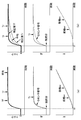
- FIG. 10 is a time chart when slip does not occur during deceleration on a high ⁇ flat road.
- FIG. 10A shows a comparative example when the torque sudden change distribution process is not performed
- FIG. 10B shows Example 1 when the torque sudden change distribution process is performed.
- the front / rear wheel torque distribution ratio St is set to 1: 1
- the accelerator pedal is released from a state where the vehicle is traveling on a flat road at a predetermined high vehicle speed
- the vehicle is decelerated at a deceleration corresponding to a predetermined coast torque.
- An example is shown.
- the regenerative torque of the front motor 1f and the rear motor 1r is generated to satisfy the required deceleration, and the vehicle is decelerated.
- FIG. 11 is a time chart when a slip occurs during deceleration on a flat road having a low ⁇ .
- FIG. 11A shows a comparative example in which the distribution process at the time of sudden torque change is not performed
- FIG. 11B shows the first embodiment when the distribution process at the time of sudden torque change is performed.
- Tf, Tr torque commands
- the average torque of the front and rear wheels also increases in accordance with Tf and Tr.
- both the first cutoff frequency ⁇ c1 and the second cutoff frequency ⁇ c2 are small values, so that the response of the Tr is corrected so as to be delayed.
- the deceleration that is reduced by the correction is added to Tf. Therefore, Tr and Tf have different values while satisfying the required deceleration. Since the absolute value of Tr is smaller than the absolute value of Tf, braking slip first occurs on the front wheels, and Tf is output after slip control. However, since no braking slip occurs on the rear wheel, the absolute value of Tr is large and the torque does not decrease. Therefore, it is possible to prevent a large drop in deceleration.
- the vehicle can be stabilized by the tire lateral force on the rear wheels. Thereafter, the absolute value of Tr also rises, and when slip occurs in the rear wheel, Tf has returned to some extent, and it is possible to avoid the rear wheel from undergoing a large braking slip. Therefore, it is possible to smoothly decelerate by suppressing the loss of deceleration compared to the comparative example. Further, by avoiding the front and rear wheels from slipping at the same time, the vehicle can be stabilized by securing the tire lateral force, and an excessive decrease in road surface ⁇ can be avoided.
- Example 1 has the following operational effects.
- a control device for an electric vehicle having a front motor 1f (front electric motor) that outputs torque to the front wheels of the vehicle and a rear motor 1r (rear electric motor) that outputs torque to the rear wheels of the vehicle, Torque distribution unit 105 (target torque calculation unit) that calculates a reference front motor torque command value Ttf and a reference rear motor torque command value Ttr (also referred to as a reference motor torque command value Ttfr) that are target torques of the front motor 1f and the rear motor 1r ), A final torque limiting unit 109 (torque command unit) that outputs a final torque command value Tt3 to the front motor 1f and the rear motor 1r, and a final torque command value with respect to the reference motor torque command value Ttfr in one of the front motor 1f and the rear motor 1r A torque sudden change distribution unit 500 (control unit) that controls the achievement rate of Tt3 to be lower than the other achievement rate.
- the difference between the response on the front wheel side and the response on the rear wheel side when the accelerator pedal opening speed ⁇ APO is small is small.
- the difference between the response on the front wheel side and the response on the rear wheel side when the accelerator pedal opening speed ⁇ APO is large is large. Therefore, it is possible to suppress the front and rear wheels from simultaneously driving slip or braking slip.
- the torque sudden change distribution unit 500 compensates for the torque that decreases by reducing the achievement rate of one of the other. Therefore, even when the actual torque on the rear wheel side decreases during deceleration, the required torque Tt can be secured by compensating on the front wheel side.
- the sudden torque change distribution unit 500 determines the achievement rate of one of the vehicles when the vehicle is at a predetermined vehicle speed or more and the reference motor torque command value Ttfr) is negative indicating deceleration. make low. Therefore, simultaneous locking of the front and rear wheels can be suppressed during deceleration at a predetermined vehicle speed or higher, and vehicle stability can be ensured.
- the torque sudden change distribution unit 500 does not compensate for the torque that is reduced by lowering one achievement rate on the other.
- the torque sudden change distribution unit 500 reduces the achievement rate of one when the vehicle is less than a predetermined vehicle speed and the road surface vertical gradient SP is equal to or greater than a predetermined value, as compared to the other cases. That is, when starting on an uphill road or the like, even if the actual torque is slightly lower than the required torque Tt, it is difficult for the driver to feel uncomfortable. For example, when the front and rear wheels slip simultaneously after starting on a snowy road, the snow on the surface melts due to the slip, and the road surface ⁇ may further decrease. In addition, the post-slip control Tf, Tr corrected to suppress this slip becomes very small, and the small post-slip control Tf, Tr is output at the same time.
- the achievement rate of one of the vehicles is reduced compared to the other cases, thereby suppressing the simultaneous slip of the front and rear wheels.
- a stable running state can be achieved.
- the sudden torque change distribution unit 500 lowers one achievement rate when the vehicle starts or decelerates when the road surface vertical gradient SP is equal to or greater than a predetermined value. Therefore, it is possible to achieve a stable traveling state while suppressing the simultaneous slip of the front and rear wheels.
- One is the rear motor 1r. Since the stability related to the yaw moment of the vehicle has a high correlation with the tire lateral force on the rear wheel side, the stability of the vehicle can be ensured by delaying the torque response on the rear wheel side.
- the torque response on the rear wheel side is delayed by appropriately setting the cutoff frequency of the low-pass filter processing.
- the torque response on the rear wheel side may be delayed by other methods.
- the torque command output timing to the rear wheels may be delayed using a timer or the like, or the response may be delayed by limiting the change of the torque command value by limiter processing, and there is no particular limitation.
- a control device for an electric vehicle having a front electric motor that outputs torque to the front wheels of the vehicle and a rear electric motor that outputs torque to the rear wheels of the vehicle has a torque command value for the front electric motor and the rear electric motor. While the torque command value to be output and the torque command value are changing, the front electric motor torque command value and the rear electric motor torque command value are larger than a predetermined value so that the difference between And a control unit for controlling the electric motor and the rear electric motor.
- the control unit increases the difference as the road surface gradient increases.
- the control unit includes a calculation unit that calculates a reference torque command value based on a preset reference torque distribution ratio between the front electric motor and the rear electric motor. After the change amount of the torque command value becomes less than a predetermined value, the torque command value is gradually returned to the reference torque command value.
- the control unit includes a calculation unit that calculates a reference torque command value based on a preset reference torque distribution ratio between the front electric motor and the rear electric motor. Increases the difference by changing the reference torque distribution ratio.
- the control unit controls the front electric motor and the rear electric motor so that the difference is not more than a preset value.
- the control unit is configured so that the torque command value of the rear electric motor is smaller than the torque command value of the front electric motor. Control the electric motor.
- a control device for an electric vehicle having a front electric motor that outputs torque to the front wheels of the vehicle and a rear electric motor that outputs torque to the rear wheels of the vehicle has a large longitudinal gradient of the road surface.
- the control unit controls the front electric motor and the rear electric motor so as to increase the difference between the torque command value of the front electric motor and the torque command value of the rear electric motor.
- the control unit controls the front electric motor and the rear electric motor so that the difference becomes larger than a predetermined value while the torque command value is changing.
- control unit may change the torque command value to the front electric motor and the rear electric motor after the change amount of the torque command value is less than a predetermined value. Are gradually returned toward the reference torque command value based on the preset reference torque distribution ratio.
- a control method for an electric vehicle having a front electric motor that outputs torque to the front wheels of the vehicle and a rear electric motor that outputs torque to the rear wheels of the vehicle includes the front electric motor and the A torque command step for outputting a torque command value to the rear electric motor, and a difference between the torque command value of the front electric motor and the torque command value of the rear electric motor is a predetermined value while the torque command value is changing. And a control step for controlling the front electric motor and the rear electric motor so as to be larger.
- the control step includes a step of increasing the difference as the road surface longitudinal gradient increases.
- control step includes a calculation step of calculating a reference torque command value based on a preset reference torque distribution ratio between the front electric motor and the rear electric motor. And a step of gradually returning the torque command value to the reference torque command value after the change amount of the torque command value becomes less than a predetermined value.
- control step includes a calculation step of calculating a reference torque command value based on a preset reference torque distribution ratio between the front electric motor and the rear electric motor. Comprises a step of increasing the difference by changing the reference torque distribution ratio.
- control step includes a step of controlling the front electric motor and the rear electric motor so that the difference is equal to or less than a predetermined value set in advance.
- control step includes the front electric motor and the rear electric motor so that the torque command value of the rear electric motor is smaller than the torque command value of the front electric motor. The step of controlling the electric motor is provided.
- an electric vehicle control system in another aspect, includes a front electric motor that outputs torque to the front wheels of the vehicle, a rear electric motor that outputs torque to the rear wheels of the vehicle, the front electric motor, and the rear electric motor.
- a control unit that controls a motor, and the control unit outputs a torque command value to the front electric motor and the rear electric motor, and while the torque command value is changing,
- a controller that controls the front electric motor and the rear electric motor so that a difference between a torque command value of the front electric motor and a torque command value of the rear electric motor is greater than a predetermined value.
- the control unit increases the difference as the road surface gradient increases.
- control unit includes a calculation unit that calculates a reference torque command value based on a preset reference torque distribution ratio between the front electric motor and the rear electric motor. After the change amount of the torque command value becomes less than a predetermined value, the torque command value is gradually returned to the reference torque command value.
Abstract
Provided is a control device for an electric vehicle with which it is possible to prevent front and rear wheels from slipping simultaneously. This control device for an electric vehicle controls a front electric motor and a rear electric motor such that a difference between a torque command value of the front electric motor and a torque command value of a rear electric motor becomes greater than a predetermined value.
Description
本発明は、電動車両の制御装置、制御システム及び制御方法に関する。
The present invention relates to an electric vehicle control device, a control system, and a control method.
従来、特許文献1に記載の電動車両の制御装置では、前輪はエンジンにより、後輪は電動モータにより駆動される四輪駆動車において、傾斜角が大きいほど、すなわち坂道が急なほど発進時のモータトルクを大きくし、前後輪のトルク配分を調整することで坂道でのスリップを抑制している。
Conventionally, in the control apparatus for an electric vehicle described in Patent Document 1, in a four-wheel drive vehicle in which the front wheels are driven by the engine and the rear wheels are driven by the electric motor, the larger the inclination angle, that is, the steeper the slope, Slip on the slope is suppressed by increasing the motor torque and adjusting the torque distribution of the front and rear wheels.
しかしながら、特許文献1のように、運転者の操作が路面に対して過大な場合、前後輪のトルク配分を行ったとしても、前後輪が同時にスリップするおそれがあった。
本発明の目的は、前後輪が同時にスリップすることを抑制可能な電動車両の制御装置を提供することにある。 However, as inPatent Document 1, when the driver's operation is excessive with respect to the road surface, the front and rear wheels may slip at the same time even if the torque distribution of the front and rear wheels is performed.
The objective of this invention is providing the control apparatus of the electric vehicle which can suppress that a front-and-rear wheel slips simultaneously.
本発明の目的は、前後輪が同時にスリップすることを抑制可能な電動車両の制御装置を提供することにある。 However, as in
The objective of this invention is providing the control apparatus of the electric vehicle which can suppress that a front-and-rear wheel slips simultaneously.
本発明の一実施形態では、電動車両の制御装置は、フロント電動モータのトルク指令値とリア電動モータのトルク指令値との差が所定値より大きくなるように、フロント電動モータ及びリア電動モータを制御する。
In one embodiment of the present invention, the control device for an electric vehicle includes a front electric motor and a rear electric motor so that a difference between a torque command value of the front electric motor and a torque command value of the rear electric motor is larger than a predetermined value. Control.
よって、前後輪が同時に駆動スリップもしくは制動スリップすることを抑制できる。
Therefore, it is possible to prevent the front and rear wheels from simultaneously driving slip or braking slip.
〔実施例1〕
図1は実施例1の電動車両のシステム図である。実施例1の電動車両は、前輪FL,FRがフロントモータ1fにより駆動され、後輪RL,RRがリアモータ1rにより駆動される4輪駆動車である。フロントモータ1fには減速機構2fを介してディファレンシャルギア3fが接続されている。ディファレンシャルギア3fにはドライブシャフト4fが接続されている。ドライブシャフト4fには前輪FL,FRが接続されている。インバータ5fには、フロントモータ1fを制御するモータコントロールユニットMCUfを有する。同様に、リアモータ1rには減速機構2rを介してディファレンシャルギア3rが接続されている。ディファレンシャルギア3rにはドライブシャフト4rが接続されている。ドライブシャフト4rには後輪RL,RRが接続されている。インバータ5rには、リアモータ1rを制御するモータコントロールユニットMCUrを有する。 [Example 1]
FIG. 1 is a system diagram of the electric vehicle according to the first embodiment. The electric vehicle according to the first embodiment is a four-wheel drive vehicle in which front wheels FL and FR are driven by afront motor 1f, and rear wheels RL and RR are driven by a rear motor 1r. A differential gear 3f is connected to the front motor 1f via a speed reduction mechanism 2f. A drive shaft 4f is connected to the differential gear 3f. Front wheels FL and FR are connected to the drive shaft 4f. The inverter 5f has a motor control unit MCUf that controls the front motor 1f. Similarly, a differential gear 3r is connected to the rear motor 1r via a speed reduction mechanism 2r. A drive shaft 4r is connected to the differential gear 3r. Rear wheels RL and RR are connected to the drive shaft 4r. The inverter 5r has a motor control unit MCUr that controls the rear motor 1r.
図1は実施例1の電動車両のシステム図である。実施例1の電動車両は、前輪FL,FRがフロントモータ1fにより駆動され、後輪RL,RRがリアモータ1rにより駆動される4輪駆動車である。フロントモータ1fには減速機構2fを介してディファレンシャルギア3fが接続されている。ディファレンシャルギア3fにはドライブシャフト4fが接続されている。ドライブシャフト4fには前輪FL,FRが接続されている。インバータ5fには、フロントモータ1fを制御するモータコントロールユニットMCUfを有する。同様に、リアモータ1rには減速機構2rを介してディファレンシャルギア3rが接続されている。ディファレンシャルギア3rにはドライブシャフト4rが接続されている。ドライブシャフト4rには後輪RL,RRが接続されている。インバータ5rには、リアモータ1rを制御するモータコントロールユニットMCUrを有する。 [Example 1]
FIG. 1 is a system diagram of the electric vehicle according to the first embodiment. The electric vehicle according to the first embodiment is a four-wheel drive vehicle in which front wheels FL and FR are driven by a
高電圧バッテリBATは、供給電力を制御するバッテリコントロールユニットBCUを有する。高電圧バッテリBATは、複数のバッテリを接続したバッテリモジュールであり、バッテリコントロールユニットBCUは、一つのバッテリモジュールから複数のモータ(フロントモータ1f及びリアモータ1r)への供給電力を制御する。
The high voltage battery BAT has a battery control unit BCU that controls supply power. The high voltage battery BAT is a battery module in which a plurality of batteries are connected, and the battery control unit BCU controls the power supplied from one battery module to a plurality of motors (front motor 1f and rear motor 1r).
電動車両は、ブレーキペダルストローク信号を出力するストロークセンサ6と、アクセル開度信号を出力するアクセル開度センサ7と、電動モータ1の回転方向を含むモータ回転速度信号を出力するレゾルバ8f,8rと、車両の前後加速度sgを検出する前後加速度センサ12と、を有する。車両コントロールユニットCUは、シフトレバーからのレンジ位置信号と、ストロークセンサ6からのブレーキペダルストローク信号と、アクセル開度センサ7からのアクセル開度信号とを受信する。また、車両コントロールユニットCUは、レゾルバ8f,8rからのモータ回転速度信号を、モータコントロールユニットMCUf,MCUrを介して受信する。車両コントロールユニットCUは、アクセル開度等に基づいて電動モータ1の駆動トルク指令値を演算し、駆動トルク指令値に応じてフロントモータ1f,リアモータ1rを駆動する。
The electric vehicle includes a stroke sensor 6 that outputs a brake pedal stroke signal, an accelerator opening sensor 7 that outputs an accelerator opening signal, and resolvers 8f and 8r that output a motor rotation speed signal including the rotation direction of the electric motor 1. A longitudinal acceleration sensor 12 for detecting the longitudinal acceleration sg of the vehicle. The vehicle control unit CU receives a range position signal from the shift lever, a brake pedal stroke signal from the stroke sensor 6, and an accelerator opening signal from the accelerator opening sensor 7. Further, the vehicle control unit CU receives the motor rotation speed signals from the resolvers 8f and 8r via the motor control units MCUf and MCUr. The vehicle control unit CU calculates a drive torque command value of the electric motor 1 based on the accelerator opening and the like, and drives the front motor 1f and the rear motor 1r according to the drive torque command value.
ブレーキコントローラ9は、各輪に設けられた車輪速センサ10FL,10FR,10RL,10RR(以下、単に10とも記載する。)と接続され、各輪の回転速度信号を受信する。車輪速センサ10は、電磁バルスの周期から車輪速を検出する。ブレーキコントローラ9は、ストロークセンサ6により検出された運転者のブレーキ操作量に基づき、各輪の液圧によるブレーキユニットに供給するブレーキ液を調整し、各輪の制動トルクを制御する。モータコントロールユニットMCUf,MCUr、車両コントロールユニットCU及びブレーキコントローラ9の情報通信は、CAN通信線11を介して行われる。
The brake controller 9 is connected to wheel speed sensors 10FL, 10FR, 10RL, 10RR (hereinafter also simply referred to as 10) provided on each wheel, and receives a rotation speed signal of each wheel. The wheel speed sensor 10 detects the wheel speed from the period of the electromagnetic pulse. The brake controller 9 adjusts the brake fluid supplied to the brake unit by the hydraulic pressure of each wheel based on the amount of brake operation of the driver detected by the stroke sensor 6, and controls the braking torque of each wheel. Information communication between the motor control units MCUf and MCUr, the vehicle control unit CU, and the brake controller 9 is performed via the CAN communication line 11.
図2は、実施例1の電動車両の制御ブロック図である。
運転者要求トルク演算部101は、アクセル開度APO及び車速VSPに基づき運転者の要求トルクTdを演算する。運転者要求トルクTdは、アクセル開度APOが高いほど大きな値が設定される。
回生トルク受け入れ部102は、他の演算部において演算された要求制動トルクに基づく要求回生トルクTrgを受け入れ、運転者要求トルクTdを補正する。
要求トルク受け入れ部103では、他の演算部において演算された要求駆動トルクTofを受け入れ、運転者要求トルクTdを補正する。これら、運転者要求トルク演算部101,回生トルク受け入れ部102及び要求トルク受け入れ部103の各指令値から得られるフロントモータ1f及びリアモータ1rの合計軸トルク指令値を、車両の要求トルクTtとして出力する。 FIG. 2 is a control block diagram of the electric vehicle according to the first embodiment.
The driver requesttorque calculation unit 101 calculates the driver request torque Td based on the accelerator opening APO and the vehicle speed VSP. The driver request torque Td is set to a larger value as the accelerator opening APO is higher.
The regenerativetorque receiving unit 102 receives the required regenerative torque Trg based on the required braking torque calculated by the other calculation units, and corrects the driver required torque Td.
The requiredtorque receiving unit 103 receives the required drive torque Tof calculated by the other calculation units and corrects the driver required torque Td. The total shaft torque command value of the front motor 1f and the rear motor 1r obtained from the command values of the driver request torque calculation unit 101, the regenerative torque reception unit 102, and the request torque reception unit 103 is output as the vehicle request torque Tt. .
運転者要求トルク演算部101は、アクセル開度APO及び車速VSPに基づき運転者の要求トルクTdを演算する。運転者要求トルクTdは、アクセル開度APOが高いほど大きな値が設定される。
回生トルク受け入れ部102は、他の演算部において演算された要求制動トルクに基づく要求回生トルクTrgを受け入れ、運転者要求トルクTdを補正する。
要求トルク受け入れ部103では、他の演算部において演算された要求駆動トルクTofを受け入れ、運転者要求トルクTdを補正する。これら、運転者要求トルク演算部101,回生トルク受け入れ部102及び要求トルク受け入れ部103の各指令値から得られるフロントモータ1f及びリアモータ1rの合計軸トルク指令値を、車両の要求トルクTtとして出力する。 FIG. 2 is a control block diagram of the electric vehicle according to the first embodiment.
The driver request
The regenerative
The required
配分比調停部104では、駆動力配分比指令Std及び回生制動力配分比指令Strgに基づいて、要求トルクTtをフロントモータ1fとリアモータ1rとに配分する際の配分比Stを決定する。駆動力配分比指令とは、図外の駆動力配分比演算部において、走行状態に応じて、前輪と後輪の駆動力配分比を演算し、出力された指令である。回生制動力配分比指令とは、図外の回生制動力配分比演算部において、前輪と後輪の回生制動力配分比を演算し、出力された指令である。配分比調停部104では、これら各配分比と、現在の走行状態に基づいて配分比Stを決定する。 トルク配分部105では、要求トルクTtと配分比Stに基づいて基準フロントモータトルク指令値Ttfと、基準リアモータトルク指令値Ttrを演算する。以下、フロントモータ1f及びリアモータ1rを総称して基準モータトルク指令値Ttfrと記載する。この基準モータトルク指令値Ttfrがフロントモータ1f及びリアモータ1rを制御する際の目標トルクに相当する。
The distribution ratio arbitration unit 104 determines a distribution ratio St for distributing the required torque Tt to the front motor 1f and the rear motor 1r based on the driving force distribution ratio command Std and the regenerative braking force distribution ratio command Strg. The driving force distribution ratio command is a command that is output by calculating a driving force distribution ratio between the front wheels and the rear wheels in accordance with the running state in a driving force distribution ratio calculation unit (not shown). The regenerative braking force distribution ratio command is a command output by calculating a regenerative braking force distribution ratio between the front wheels and the rear wheels in a regenerative braking force distribution ratio calculation unit (not shown). The distribution ratio arbitration unit 104 determines the distribution ratio St based on each distribution ratio and the current running state. The torque distribution unit 105 calculates a reference front motor torque command value Ttf and a reference rear motor torque command value Ttr based on the required torque Tt and the distribution ratio St. Hereinafter, the front motor 1f and the rear motor 1r are collectively referred to as a reference motor torque command value Ttfr. This reference motor torque command value Ttfr corresponds to a target torque for controlling the front motor 1f and the rear motor 1r.
加減速時配分部600は、アクセルペダル開度APOと、ブレーキペダルストロークBPSと、基準フロントモータトルク指令値Ttfと、基準リアモータトルク指令値Ttryと、縦断勾配SPとに基づいて、トルク急変時に配分比Stを変更し、加減速時基準フロントモータトルク指令値Ttfy及び加減速時基準リアモータトルク指令値Ttry(以下、これらを総称して加減速時基準モータトルク指令値Ttfryとも記載する。)を演算する。これにより、前輪と後輪のトルク指令値との間に所定の差を生じさせ、前輪と後輪とが同時にスリップすることを回避するものである。詳細については後述する。
Acceleration / deceleration distribution unit 600 is based on accelerator pedal opening APO, brake pedal stroke BPS, reference front motor torque command value Ttf, reference rear motor torque command value Ttry, and longitudinal gradient SP. The distribution ratio St is changed, and the acceleration / deceleration reference front motor torque command value Ttfy and the acceleration / deceleration reference rear motor torque command value Ttry (hereinafter collectively referred to as acceleration / deceleration reference motor torque command value Ttfry) Is calculated. Thus, a predetermined difference is generated between the torque command values of the front wheels and the rear wheels, and the front wheels and the rear wheels are prevented from slipping at the same time. Details will be described later.
トルク制限部106では、後述するトルク制限値選択部205により選択された正トルク制限値Tplimf,Tplimr及び負トルク制限値Tnlimf,Tnlimr(以下、これら制限値をトルク制限値Tlimと記載する。)によって制限された第1フロントモータトルク指令値Ttf1と、第1リアモータトルク指令値Ttr1(以下、これら指令値を第1トルク指令値Tt1と記載する。)を演算する。言い換えると、加減速時基準モータトルク指令値Ttfryがトルク制限値Tlim内となるように補正される。
The torque limiter 106 uses positive torque limit values Tplimf, Tplimr and negative torque limit values Tnlimf, Tnlimr (hereinafter, these limit values are referred to as torque limit values Tlim) selected by a torque limit value selection unit 205 described later. The limited first front motor torque command value Ttf1 and the first rear motor torque command value Ttr1 (hereinafter, these command values are referred to as the first torque command value Tt1) are calculated. In other words, the acceleration / deceleration reference motor torque command value Ttfry is corrected to be within the torque limit value Tlim.
トルク再配分部107では、各モータの第1トルク指令値Tt1の合計が要求トルクTt未満のときは、第1トルク指令値Tt1がトルク制限値Tlimよりも低いモータに、各モータの第1トルク指令値Tt1の合計が要求トルクTtを越えない範囲でトルクを再配分した第2フロントモータトルク指令値Ttf2と、第2リアモータトルク指令値Ttr2(以下、これら指令値を第2トルク指令値Tt2と記載する。)を演算する。
In the torque redistribution unit 107, when the sum of the first torque command values Tt1 of the respective motors is less than the required torque Tt, the first torque of each motor is changed to a motor whose first torque command value Tt1 is lower than the torque limit value Tlim. A second front motor torque command value Ttf2 obtained by redistributing the torque within a range where the total of the command values Tt1 does not exceed the required torque Tt, and a second rear motor torque command value Ttr2 (hereinafter, these command values are referred to as a second torque command value Tt2). Is calculated).
スリップ制御部108では、車輪速svと、前後加速度sgと、後述する温度保護部302f,302rのトルク指令値に基づいて、車輪にスリップが発生しているか否かを判断し、スリップ(駆動スリップ、制動スリップの両方を含む)しているときは、スリップが生じている車輪と接続されたモータトルクへのトルク制限量を演算する。 最終トルク制限部109では、第2トルク指令値Tt2に対し、スリップ制御部108で演算されたトルク制限量に基づいて決定された最終トルク指令値Tt3を各モータ1f,1rに出力する。
The slip control unit 108 determines whether or not a slip has occurred on the wheel based on the wheel speed sv, the longitudinal acceleration sg, and torque command values of the temperature protection units 302f and 302r, which will be described later. When the braking slip is included), the torque limit amount to the motor torque connected to the wheel where the slip occurs is calculated. The final torque limiting unit 109 outputs the final torque command value Tt3 determined based on the torque limit calculated by the slip control unit 108 to the motors 1f and 1r with respect to the second torque command value Tt2.
最大トルク制限値演算部201では、フロントモータ1fの回転速度Vmfと、リアモータ1rの回転速度Vmrとに基づいて、各モータの正トルク制限値Tplimtf,Tplimtr及び負トルク制限値Tnlimtf,Tnlimtr(以下、Tplimtf,Tplimtr,Tnlimtf,Tnlimtrを最大トルク制限値Tlimaxとも記載する。)を演算する。これは、モータの回転数に対するトルク特性が予め定められており、ある回転速度に対して最大限出力可能なトルク値をマップ等から設定する。
In the maximum torque limit value calculation unit 201, based on the rotation speed Vmf of the front motor 1f and the rotation speed Vmr of the rear motor 1r, the positive torque limit values Tplimtf and Tplimtr and the negative torque limit values Tnlimtf and Tnlimtr (hereinafter, Tplimtf, Tplimtr, Tnlimtf, and Tnlimtr are also referred to as maximum torque limit value Tlimax). This is because a torque characteristic with respect to the rotational speed of the motor is determined in advance, and a torque value that can be output to a maximum at a certain rotational speed is set from a map or the like.
電力配分部202では、高電圧バッテリBATから供給する電力の上限値であるバッテリ電力制限値Wlimと、配分比Stとに基づいて、フロントモータ1fの第1電力制限値Wlimf1及びリアモータ1rの第1電力制限値Wlimr1(以下、Wlimf1及びWlimr1を第1電力制限値Wlim1とも記載する。)を演算する。すなわち、一つの高電圧バッテリBATから複数のモータに電力を供給する際、各モータの消費電力が個別的に決定されると、トータルの消費電力がバッテリ電力制限値Wlimを超えるおそれがある。また、各モータの消費電力を個別的に決定後、消費電力がバッテリ電力制限値Wlimを超えないように各モータのトルクを修正することも考えられるが、繰り返し演算が必要となる。これに対し、実施例1では、予め電力配分を行い、この電力配分に基づく各モータの第1電力制限値Wlim1を設定することで、バッテリ電力制限値Wlimを超えることなく、効果的に各モータトルクを制御できる。
In the power distribution unit 202, the first power limit value Wlimf1 of the front motor 1f and the first power of the rear motor 1r are based on the battery power limit value Wlim that is the upper limit value of power supplied from the high-voltage battery BAT and the distribution ratio St. A power limit value Wlimr1 (hereinafter, Wlimf1 and Wlimr1 are also referred to as a first power limit value Wlim1) is calculated. That is, when power is supplied to a plurality of motors from one high-voltage battery BAT, if the power consumption of each motor is determined individually, the total power consumption may exceed the battery power limit value Wlim. In addition, after determining the power consumption of each motor individually, it is conceivable to correct the torque of each motor so that the power consumption does not exceed the battery power limit value Wlim. On the other hand, in the first embodiment, power is allocated in advance, and the first power limit value Wlim1 of each motor based on this power distribution is set, so that each motor can be effectively applied without exceeding the battery power limit value Wlim. Torque can be controlled.
電力再配分部203では、各モータのうち、あるモータの第1電力制限値Wlim1から実際の消費電力Wx(x=f,r)を除いた余剰電力を他のモータの電力制限値Wlim1に配分したフロントモータ1fの第2電力制限値Wlimf2及びリアモータ1rの第2電力制限値Wlimr2(以下、Wlimf2及びWlimr2を第2電力制限値Wlim2とも記載する。)を演算する。
The power redistribution unit 203 distributes the surplus power obtained by subtracting the actual power consumption Wx (x = f, r) from the first power limit value Wlim1 of one motor among the motors to the power limit value Wlim1 of other motors. The second power limit value Wlimf2 of the front motor 1f and the second power limit value Wlimr2 of the rear motor 1r (hereinafter, Wlimf2 and Wlimr2 are also referred to as the second power limit value Wlim2) are calculated.
第1トルク制限値演算部204では、高電圧バッテリBATのバッテリ電位Vbatと、回転速度Vmf,Vmrと、第2電力制限値Wlim2に応じた正トルク制限値Tplimw及び負トルク制限値Tnlimw(以下、Tplimw,Tnlimwを第1トルク制限値Tlimwとも記載する。)を演算する。 トルク制限値選択部205では、最大トルク制限値Tlimmaxと第1トルク制限値Tlimwのうち、低いほうの制限値を選択し、トルク制限値Tlimとして出力する。
In the first torque limit value calculation unit 204, a positive torque limit value Tplimw and a negative torque limit value Tnlimw (hereinafter, referred to as the battery potential Vbat of the high voltage battery BAT, the rotational speeds Vmf and Vmr, and the second power limit value Wlim2). Tplimw and Tnlimw are also described as the first torque limit value Tlimw). The torque limit value selection unit 205 selects a lower limit value from the maximum torque limit value Tlimmax and the first torque limit value Tlimw, and outputs it as the torque limit value Tlim.
モータコントロールユニットMCUf及びMCUrには、トルク制限部301f,301rと、温度保護部302f,302rと、制振制御部303f,303rとを有する。トルク制限部301f,301rでは、最終トルク制限部109から出力された最終トルク指令値Tt3と、トルク制限値選択部205から出力されたトルク制限値Tlimとに基づいてモータトルク指令値を演算する。温度保護部302f,302rでは、モータに供給される電流値に基づいて演算される発熱量と、モータに取り付けられた温度センサの計測値から、モータが所定の温度以下となるようにモータトルク指令値を制限する。制振制御部303f,303rでは、ドライブシャフト4f,4rに生じる振動を抑制する制振トルクを演算し、モータトルク指令値に制振トルクを付与し、最終的にモータトルク制御を実行する。
The motor control units MCUf and MCUr include torque limiting units 301f and 301r, temperature protection units 302f and 302r, and vibration control units 303f and 303r. The torque limiters 301f and 301r calculate the motor torque command value based on the final torque command value Tt3 output from the final torque limiter 109 and the torque limit value Tlim output from the torque limit value selector 205. In the temperature protection units 302f and 302r, a motor torque command is issued so that the motor becomes a predetermined temperature or less from the calorific value calculated based on the current value supplied to the motor and the measured value of the temperature sensor attached to the motor. Limit the value. The damping control units 303f and 303r calculate damping torque that suppresses vibrations generated in the drive shafts 4f and 4r, give damping torque to the motor torque command value, and finally execute motor torque control.
(加減速時配分部について)
図3は、実施例1の加減速時配分部の詳細を表す制御ブロック図である。 トルク配分比制限部601では、縦断勾配SPに基づいてトルク配分比制限値St(f)limを算出する。トルク配分比制限値St(f)limとは、配分比Stに基づいて前輪に配分される前輪配分比St(f)の制限値であり、前輪:後輪の配分比Stが1:1の場合、St(f)は50%であり、2:1の場合、St(f)は67%である。縦断勾配SPが小さいときはSt(f)limを小さくし、縦断勾配SPが大きいときはSt(f)limを大きくする。言い換えると、平坦路であれば前輪側に配分するトルクを抑制し、勾配路であれば前輪側に大きなトルクを配分することを許容する。 偏差演算部602では、St(f)limからSt(f)を減算し、前輪側に配分するトルクの不足配分比(%)を演算する。 配分比選択部603では、不足配分比(%)と0%とのうち大きいほうの値を出力する。よって、St(f)limがSt(f)より大きい場合は、不足配分比(%)をそのまま出力し、St(f)limがSt(f)より小さい場合は、既に前輪に対して大きなトルクが配分されていると判断して0%を出力する。 絶対値処理部604では、要求トルクTtを絶対値化し、後述する不足トルク演算部605に出力する。 不足トルク演算部605では、要求トルク絶対値|Tt|に不足配分比(%)を乗算し、前輪側に加算する不足トルク、すなわち前輪側に不足していると考えられるトルクを演算する。 (About the acceleration / deceleration distribution part)
FIG. 3 is a control block diagram illustrating details of the acceleration / deceleration distribution unit according to the first embodiment. The torquedistribution ratio limiter 601 calculates a torque distribution ratio limit value St (f) lim based on the longitudinal gradient SP. The torque distribution ratio limit value St (f) lim is a limit value of the front wheel distribution ratio St (f) distributed to the front wheels based on the distribution ratio St, and the front wheel: rear wheel distribution ratio St is 1: 1. In this case, St (f) is 50%, and in the case of 2: 1, St (f) is 67%. When the longitudinal gradient SP is small, St (f) lim is decreased, and when the longitudinal gradient SP is large, St (f) lim is increased. In other words, if it is a flat road, the torque distributed to the front wheels is suppressed, and if it is a gradient road, it is allowed to distribute a large torque to the front wheels. The deviation calculating unit 602 subtracts St (f) from St (f) lim to calculate the insufficient distribution ratio (%) of the torque distributed to the front wheels. The distribution ratio selection unit 603 outputs the larger value of the shortage distribution ratio (%) and 0%. Therefore, when St (f) lim is larger than St (f), the shortage allocation ratio (%) is output as it is, and when St (f) lim is smaller than St (f), a large torque is already applied to the front wheels. Is output and 0% is output. The absolute value processing unit 604 converts the required torque Tt into an absolute value and outputs the absolute value to the below-described insufficient torque calculation unit 605. The insufficient torque calculation unit 605 multiplies the required torque absolute value | Tt | by the insufficient distribution ratio (%), and calculates the insufficient torque to be added to the front wheel side, that is, the torque considered to be insufficient on the front wheel side.
図3は、実施例1の加減速時配分部の詳細を表す制御ブロック図である。 トルク配分比制限部601では、縦断勾配SPに基づいてトルク配分比制限値St(f)limを算出する。トルク配分比制限値St(f)limとは、配分比Stに基づいて前輪に配分される前輪配分比St(f)の制限値であり、前輪:後輪の配分比Stが1:1の場合、St(f)は50%であり、2:1の場合、St(f)は67%である。縦断勾配SPが小さいときはSt(f)limを小さくし、縦断勾配SPが大きいときはSt(f)limを大きくする。言い換えると、平坦路であれば前輪側に配分するトルクを抑制し、勾配路であれば前輪側に大きなトルクを配分することを許容する。 偏差演算部602では、St(f)limからSt(f)を減算し、前輪側に配分するトルクの不足配分比(%)を演算する。 配分比選択部603では、不足配分比(%)と0%とのうち大きいほうの値を出力する。よって、St(f)limがSt(f)より大きい場合は、不足配分比(%)をそのまま出力し、St(f)limがSt(f)より小さい場合は、既に前輪に対して大きなトルクが配分されていると判断して0%を出力する。 絶対値処理部604では、要求トルクTtを絶対値化し、後述する不足トルク演算部605に出力する。 不足トルク演算部605では、要求トルク絶対値|Tt|に不足配分比(%)を乗算し、前輪側に加算する不足トルク、すなわち前輪側に不足していると考えられるトルクを演算する。 (About the acceleration / deceleration distribution part)
FIG. 3 is a control block diagram illustrating details of the acceleration / deceleration distribution unit according to the first embodiment. The torque
トルク補正量制限値演算部606では、縦断勾配SPに基づいて後述する第1トルク補正量の補正量上限値Tfhlimを設定する。縦断勾配SPが小さいときはTfhlimを小さくし、縦断勾配が大きくなるほどTfhlimを大きくし、縦断勾配SPが所定以上のときは、Tfhlimを一定値とする。すなわち、第1トルク補正量をある程度制限することで、過度の補正を抑制し、必要以上に前後輪のトルク差が拡大することを回避する。詳細は後述する。
The torque correction amount limit value calculation unit 606 sets a correction amount upper limit value Tfhlim of a first torque correction amount, which will be described later, based on the longitudinal gradient SP. When the longitudinal gradient SP is small, Tfhlim is decreased, and as the longitudinal gradient is increased, Tfhlim is increased. When the longitudinal gradient SP is equal to or greater than a predetermined value, Tfhlim is set to a constant value. That is, by restricting the first torque correction amount to some extent, excessive correction is suppressed, and an increase in the torque difference between the front and rear wheels is avoided more than necessary. Details will be described later.
アクセルペダル操作速度演算部607では、アクセルペダル開度APOを微分もしくは次回制御周期までのAPO変化量であるアクセルペダル操作速度ΔAPOを演算する。 アクセル側ローパスフィルタ608では、ΔAPOにローパスフィルタ処理を施し、アクセルペダル操作速度フィルタリング値F(ΔAPO)を演算する。これにより、アクセルペダル操作に対して実際のモータトルクの変化が追い付かない場面であっても、ΔAPOが0として出力されることを防止する。 アクセル側補正ゲイン演算部609では、F(ΔAPO)に応じたアクセル側補正ゲインK1を演算する。F(ΔAPO)が小さいときは、K1を小さな値とし、F(ΔAPO)が大きいときは、K1を大きな値とする。言い換えると、アクセルペダル操作速度ΔAPOが小さいときは、K1を0とすることで当初の配分比Stに戻し、アクセルペダル操作速度ΔAPOが大きいときは、配分比Stの変更を許容する。
Accelerator pedal operation speed calculator 607 differentiates accelerator pedal opening APO or calculates accelerator pedal operation speed ΔAPO, which is the APO change amount until the next control cycle. Accelerator-side low-pass filter 608 performs a low-pass filter process on ΔAPO to calculate an accelerator pedal operation speed filtering value F (ΔAPO). This prevents ΔAPO from being output as 0 even when the actual motor torque change does not catch up with the accelerator pedal operation. The accelerator side correction gain calculation unit 609 calculates the accelerator side correction gain K1 according to F (ΔAPO). When F (ΔAPO) is small, K1 is a small value, and when F (ΔAPO) is large, K1 is a large value. In other words, when the accelerator pedal operation speed ΔAPO is low, K1 is set to 0 to return to the initial distribution ratio St, and when the accelerator pedal operation speed ΔAPO is high, the distribution ratio St is allowed to change.
ブレーキペダル操作速度演算部610では、ブレーキペダルストローク量BPSを微分もしくは次回制御周期までのBPS変化量であるブレーキペダル操作速度ΔBSPを演算する。 ブレーキ側ローパスフィルタ611では、ΔBPSにローパスフィルタ処理を施し、ブレーキペダル操作速度フィルタリング値F(ΔBPS)を演算する。これにより、ブレーキペダル操作に対して実際のモータトルクの変化が追い付かない場面であっても、ΔBPSが0として出力されることを防止する。 ブレーキ側補正ゲイン演算部612では、F(ΔBPS)に応じたブレーキ側補正ゲインK2を演算する。F(ΔBPS)が小さいときは、K2を小さな値とし、F(ΔBPS)が大きいときは、K2を大きな値とする。言い換えると、ブレーキペダル操作速度ΔBPSが小さいときは、K2を0とすることで当初の配分比Stに戻し、ブレーキペダル操作速度ΔBPSが大きいときは、配分比Stの変更を許容する。
The brake pedal operation speed calculation unit 610 differentiates the brake pedal stroke amount BPS or calculates the brake pedal operation speed ΔBSP, which is the BPS change amount until the next control cycle. The brake-side low-pass filter 611 performs a low-pass filter process on ΔBPS and calculates a brake pedal operation speed filtering value F (ΔBPS). This prevents ΔBPS from being output as 0 even when the actual motor torque change does not catch up with the brake pedal operation. The brake side correction gain calculation unit 612 calculates a brake side correction gain K2 corresponding to F (ΔBPS). When F (ΔBPS) is small, K2 is a small value, and when F (ΔBPS) is large, K2 is a large value. In other words, when the brake pedal operation speed ΔBPS is low, K2 is set to 0 to return to the initial distribution ratio St, and when the brake pedal operation speed ΔBPS is high, the distribution ratio St is allowed to change.
ゲイン選択部613では、アクセル側補正ゲインK1とブレーキ側補正ゲインK2とのうち大きいほうのゲインを選択し、後述するゲイン乗算部614に出力する。 ゲイン乗算部614では、不足トルク演算部605で演算された不足トルクにK1もしくはK2のゲインを乗算し、トルク変化時不足トルクを演算する。アクセルペダル操作速度ΔAPOやブレーキペダル操作速度ΔBPSが小さいときは、K1やK2は0に設定されているため、不足トルクが出力されることはない。一方、アクセルペダル操作速度ΔAPOやブレーキペダル操作速度ΔBPSが所定値以上の場合は、トルク急変時であるため、不足トルクにゲインを乗算したトルク変化時不足トルクを出力する。
The gain selection unit 613 selects a larger one of the accelerator side correction gain K1 and the brake side correction gain K2, and outputs the selected gain to the gain multiplication unit 614 described later. The gain multiplication unit 614 multiplies the insufficient torque calculated by the insufficient torque calculation unit 605 by the gain of K1 or K2, and calculates the insufficient torque when the torque changes. When the accelerator pedal operation speed ΔAPO and the brake pedal operation speed ΔBPS are small, K1 and K2 are set to 0, so that insufficient torque is not output. On the other hand, when the accelerator pedal operation speed ΔAPO and the brake pedal operation speed ΔBPS are equal to or higher than a predetermined value, the torque is suddenly changed, and therefore, the insufficient torque at the time of torque change obtained by multiplying the insufficient torque by the gain is output.
トルク補正量選択部615では、トルク補正量制限値演算部606で演算された補正量上限値Tfhlimと、ゲイン乗算部614で演算されたトルク急変時不足トルクとのうち、小さい方のトルクを第1トルク補正量として出力する。よって、例えば登坂路において急激なアクセルペダルの踏み込み操作を行い、配分比Stの補正によって大きなトルク変化時不足トルクが演算されたとしても、補正量上限値Tfhlimを超えない値が出力される。
The torque correction amount selection unit 615 applies the smaller torque of the correction amount upper limit value Tfhlim calculated by the torque correction amount limit value calculation unit 606 and the torque shortage insufficient torque calculated by the gain multiplication unit 614 to the smaller one. Output as 1 torque correction amount. Therefore, for example, even if the accelerator pedal is suddenly depressed on an uphill road and the insufficient torque at the time of a large torque change is calculated by correcting the distribution ratio St, a value not exceeding the correction amount upper limit value Tfhlim is output.
符号抽出部616では、要求トルクTtの符号を抽出し、後述する符号乗算部617に出力する。 符号乗算部617では、第1トルク補正量に要求トルクTtの符号を乗算し、最終的なトルク補正量を演算する。 加減速時基準フロントモータトルク指令値演算部618では、基準フロントモータトルク指令値Ttfにトルク補正量を加算し、加減速時基準フロントモータトルク指令値Ttfxを出力する。 加減速時基準リアモータトルク指令値演算部619では、要求トルクTtから加減速時基準フロントモータトルク指令値Ttfxを減算し、加減速時基準リアモータトルク指令値Ttrxを出力する。よって、配分比Stが変更されたとしても、要求トルクTtが変更されることはない。
The code extraction unit 616 extracts the sign of the required torque Tt and outputs it to the code multiplication unit 617 described later. The sign multiplier 617 multiplies the sign of the required torque Tt by the first torque correction amount to calculate the final torque correction amount. Acceleration / deceleration reference front motor torque command value calculation unit 618 adds a torque correction amount to reference front motor torque command value Ttf, and outputs an acceleration / deceleration reference front motor torque command value Ttfx. Acceleration / deceleration reference rear motor torque command value calculation unit 619 subtracts acceleration / deceleration reference front motor torque command value Ttfx from request torque Tt, and outputs acceleration / deceleration reference rear motor torque command value Ttrx. Therefore, even if the distribution ratio St is changed, the required torque Tt is not changed.
〔加減速時配分処理〕
(登坂路発進時の作用)
図4は、高μの登坂路における発進時においてスリップが生じない場合のタイムチャートである。図4(a)は、トルク急変時配分処理を行わない場合の比較例を表し、図4(b)は、トルク急変時配分処理を行った場合の実施例1を表す。尚、このタイムチャートでは、前後輪トルクの配分比Stを1:1とし、登坂路で停車している状態から発進する例を示す。よって、停車状態において、前後加速度センサ12(以下、Gセンサとも記載する。)の前後加速度sgは、坂路分だけオフセットした値を示す。また、フロントモータトルク指令値をTfと記載し、リアモータトルク指令値をTrと記載する。また、前輪車輪速を前輪svと記載し、後輪車輪速を後輪svと記載する。 [Allocation processing during acceleration / deceleration]
(Action when starting uphill)
FIG. 4 is a time chart when no slip occurs when starting on a high μ uphill road. FIG. 4A shows a comparative example when the torque sudden change distribution process is not performed, and FIG. 4B shows Example 1 when the torque sudden change distribution process is performed. This time chart shows an example of starting from a state where the front and rear wheel torque distribution ratio St is 1: 1 and the vehicle is stopped on an uphill road. Therefore, in the stop state, the longitudinal acceleration sg of the longitudinal acceleration sensor 12 (hereinafter also referred to as G sensor) indicates a value offset by the amount corresponding to the slope. Further, the front motor torque command value is described as Tf, and the rear motor torque command value is described as Tr. Further, the front wheel speed is described as a front wheel sv, and the rear wheel speed is described as a rear wheel sv.
図4(a)に示す比較例の場合、時刻t1において、運転者がアクセルペダルを踏みこみ、発進すると、前後輪にアクセルペダル開度と配分比Stに応じたトルク指令Tf,Trが出力され、Tf,Trの平均トルクもTf,Trと一致して上昇する。よって、前輪sv及び後輪svは共に上昇する。
In the case of the comparative example shown in FIG. 4A, when the driver depresses the accelerator pedal at the time t1 and starts, torque commands Tf and Tr corresponding to the accelerator pedal opening and the distribution ratio St are output to the front and rear wheels. The average torque of Tf and Tr also increases in accordance with Tf and Tr. Therefore, both the front wheel sv and the rear wheel sv rise.
これに対し、図4(b)に示す実施例1の場合、アクセル側補正ゲインK1が設定されると共に、登坂路であることから縦断勾配SPに応じた補正量上限値Tfhlimも大きくなり、前輪へのトルク配分が大きくされた補正後Tfとなる。同時に、後輪へのトルク配分は抑制され、補正後Trは小さくなる。補正後Tfと補正後Trの合計トルクは要求トルクTtと一致するため、比較例と同様に走行し、運転者に違和感を与えることはない。
On the other hand, in the case of the first embodiment shown in FIG. 4B, the accelerator side correction gain K1 is set, and since it is an uphill road, the correction amount upper limit value Tfhlim corresponding to the longitudinal gradient SP is increased, and the front wheels The corrected torque distribution Tf is obtained by increasing the torque distribution to. At the same time, torque distribution to the rear wheels is suppressed, and the corrected Tr becomes small. Since the total torque of the corrected Tf and the corrected Tr matches the required torque Tt, the vehicle travels in the same manner as in the comparative example and does not give the driver a sense of incongruity.
図5は、低μの登坂路における発進時においてスリップが生じた場合のタイムチャートである。図5(a)は、トルク急変時配分処理を行わない場合の比較例を表し、図5(b)は、トルク急変時配分処理を行った場合の実施例1を表す。 図5(a)に示す比較例の場合、時刻t1において、運転者がアクセルペダルを更に踏みこみ、発進すると、前後輪にアクセ11ルペダル開度に応じたトルク指令Tf,Trが出力され、前後輪の平均トルクもTf,Trと一致して上昇する。このとき、低μのため、前後輪両方が同時にスリップし、前輪sv及び後輪svは共に大きく上昇する。そして、スリップ制御によってTf,Trが補正され、スリップ制御後Tf,Trが出力される。よって、スリップ制御後Tf,Trは大きく減少し、前輪sv及び後輪svは共に大きく低下し、前後加速度sgも大きく低下してしまう。尚、この例では、スリップ制御後に前進走行状態を継続できた例を示しているが、雪道の登坂路において、発進後に前後輪が同時にスリップすると、スリップによって表面の雪が溶け、更に路面μが低下する場合がある。この場合、このスリップを抑制するために補正したスリップ制御後Tf,Trは非常に小さくなり、小さなスリップ制御後Tf,Trが同時に出力されるため、登坂路を登れないおそれがある。
FIG. 5 is a time chart when a slip occurs when starting on a low μ uphill road. FIG. 5A shows a comparative example when the torque sudden change distribution process is not performed, and FIG. 5B shows Example 1 when the torque sudden change distribution process is performed. In the case of the comparative example shown in FIG. 5A, when the driver further depresses the accelerator pedal at the time t1 and starts, torque commands Tf and Tr corresponding to the accelerator pedal opening are output to the front and rear wheels. The average torque of the wheel also increases in accordance with Tf and Tr. At this time, because of the low μ, both the front and rear wheels slip simultaneously, and both the front wheel sv and the rear wheel sv rise greatly. Then, Tf and Tr are corrected by slip control, and Tf and Tr are output after slip control. Therefore, after the slip control, Tf and Tr are greatly reduced, both the front wheel sv and the rear wheel sv are greatly reduced, and the longitudinal acceleration sg is also greatly reduced. In this example, the forward running state can be continued after the slip control. However, when the front and rear wheels slip simultaneously after starting on a snowy road, the snow on the surface is melted by the slip, and the road surface μ is further increased. May decrease. In this case, Tf and Tr after slip control corrected to suppress this slip are very small, and Tf and Tr after small slip control are output at the same time.
これに対し、図5(b)に示す実施例1の場合、アクセル側補正ゲインK1が設定されると共に、登坂路であることから縦断勾配SPに応じた補正量上限値Tfhlimも大きくなり、前輪へのトルク配分が大きくされた補正後Tfとなる。同時に、後輪へのトルク配分は抑制され、補正後Trは小さくなる。
On the other hand, in the case of the first embodiment shown in FIG. 5B, the accelerator side correction gain K1 is set, and since it is an uphill road, the correction amount upper limit value Tfhlim corresponding to the longitudinal gradient SP increases, and the front wheels The corrected torque distribution Tf is obtained by increasing the torque distribution to. At the same time, torque distribution to the rear wheels is suppressed, and the corrected Tr becomes small.
時刻t2において、前輪にスリップが発生し、スリップ制御後Tfが出力される。しかしながら、後輪にはスリップが生じていないためTrが大きくトルクダウンすることはない。よって、前後加速度sgの大きな落ち込みを防止できる。また、前輪がスリップに伴いタイヤ横力が低下したとしても、後輪のタイヤ横力により車両を安定化できる。その後、Trも上昇し、後輪にスリップが発生する際には、Tfがある程度復帰しており、後輪が大きくスリップすることを回避できる。よって、平均トルクは運転者の要求トルクより若干低下するものの、比較例に比べて大きな前後加速度sgの落ち込みを防止することで、スムーズに発進できる。尚、雪道の登坂路において、前後輪が同時にスリップすることを回避することで、タイヤ横力の確保による車両安定化を図ることができると共に、過剰な路面μの低下を回避でき、登坂路を登れないという事態を効果的に回避できる。尚、時刻t3において、アクセルペダル操作速度ΔAPOが低下すると、アクセル側補正ゲインK1が小さくなり、最終的に0となる。これに伴い、Tf,Trは徐々に近づき、配分比Stに応じたトルクが出力される。
At time t2, slip occurs on the front wheels, and Tf is output after slip control. However, since no slip occurs in the rear wheel, Tr does not greatly reduce the torque. Therefore, a large drop in the longitudinal acceleration sg can be prevented. Further, even if the tire lateral force is reduced due to the slip of the front wheel, the vehicle can be stabilized by the tire lateral force of the rear wheel. Thereafter, Tr also rises, and when slip occurs in the rear wheel, Tf has returned to some extent, and it is possible to avoid the rear wheel from slipping significantly. Therefore, although the average torque is slightly lower than the driver's required torque, the vehicle can start smoothly by preventing a large drop in the longitudinal acceleration sg compared to the comparative example. In addition, by avoiding the front and rear wheels from slipping at the same time on a snowy road, it is possible to stabilize the vehicle by securing the tire lateral force and to avoid an excessive decrease in the road surface μ. It is possible to effectively avoid the situation of not being able to climb. When the accelerator pedal operation speed ΔAPO decreases at time t3, the accelerator side correction gain K1 decreases and finally becomes zero. Along with this, Tf and Tr gradually approach, and torque according to the distribution ratio St is output.
以上説明したように、実施例1にあっては下記に列挙する作用効果が得られる。
(1)車両の前輪にトルクを出力するフロントモータ1f(フロント電動モータ)と、車両の後輪にトルクを出力するリアモータ1r(リア電動モータ)と、を有する電動車両の制御装置であって、フロントモータ1f及びリアモータ1rにトルク指令値Tf,Trを出力する最終トルク制限部109(トルク指令部)と、トルク指令値Tf,Trが変化している間は、フロントモータ1fのトルク指令値Tfとリアモータ1rのトルク指令値Trとの差(以下、前後輪トルク差と記載する。)が所定値より大きくなるように制御する加減速時配分部600(制御部)と、を備えた。 よって、前後輪が同時に駆動スリップもしくは制動スリップすることを抑制できる。 As described above, the effects listed below are obtained in the first embodiment.
(1) A control device for an electric vehicle having afront motor 1f (front electric motor) that outputs torque to the front wheels of the vehicle and a rear motor 1r (rear electric motor) that outputs torque to the rear wheels of the vehicle, The final torque limiting unit 109 (torque command unit) that outputs the torque command values Tf and Tr to the front motor 1f and the rear motor 1r, and while the torque command values Tf and Tr are changing, the torque command value Tf of the front motor 1f And an acceleration / deceleration distribution unit 600 (control unit) that controls the difference between the torque command value Tr of the rear motor 1r (hereinafter referred to as front and rear wheel torque difference) to be larger than a predetermined value. Therefore, it is possible to suppress the front and rear wheels from simultaneously driving slip or braking slip.
(1)車両の前輪にトルクを出力するフロントモータ1f(フロント電動モータ)と、車両の後輪にトルクを出力するリアモータ1r(リア電動モータ)と、を有する電動車両の制御装置であって、フロントモータ1f及びリアモータ1rにトルク指令値Tf,Trを出力する最終トルク制限部109(トルク指令部)と、トルク指令値Tf,Trが変化している間は、フロントモータ1fのトルク指令値Tfとリアモータ1rのトルク指令値Trとの差(以下、前後輪トルク差と記載する。)が所定値より大きくなるように制御する加減速時配分部600(制御部)と、を備えた。 よって、前後輪が同時に駆動スリップもしくは制動スリップすることを抑制できる。 As described above, the effects listed below are obtained in the first embodiment.
(1) A control device for an electric vehicle having a
(2)加減速時配分部600は、路面の縦断勾配SPが大きいほど、前後輪トルク差を大きくする。よって、低μの登坂路における発進時や減速時に前後輪同時スリップを抑制しつつ、安定した走行状態を達成できる。
(3)予め設定されたフロントモータ1fとリアモータ1rの配分比St(基準トルク配分比)に基づく基準モータトルク指令値Ttfr(基準トルク指令値)を演算するトルク配分部105(演算部)を有し、加減速時配分部600は、トルク指令値Tf,Trの変化量が所定値未満となった後、トルク指令値Tf,Trを徐々に基準モータトルク指令値Ttfrに戻す。 すなわち、トルク変化が小さい場面では、前後輪同時スリップが生じにくいため、基準モータトルク指令値Ttfrに戻すことで、安定した走行状態を達成できる。 (2) The acceleration /deceleration distribution unit 600 increases the front-rear wheel torque difference as the road surface vertical gradient SP increases. Therefore, it is possible to achieve a stable traveling state while suppressing simultaneous slipping of the front and rear wheels when starting or decelerating on a low μ uphill road.
(3) A torque distribution unit 105 (calculation unit) that calculates a reference motor torque command value Ttfr (reference torque command value) based on a preset distribution ratio St (reference torque distribution ratio) between thefront motor 1f and the rear motor 1r is provided. Then, the acceleration / deceleration distribution unit 600 gradually returns the torque command values Tf and Tr to the reference motor torque command value Ttfr after the change amount of the torque command values Tf and Tr becomes less than a predetermined value. That is, in a scene where the torque change is small, it is difficult for the front and rear wheels to slip at the same time. Therefore, by returning to the reference motor torque command value Ttfr, a stable running state can be achieved.
(3)予め設定されたフロントモータ1fとリアモータ1rの配分比St(基準トルク配分比)に基づく基準モータトルク指令値Ttfr(基準トルク指令値)を演算するトルク配分部105(演算部)を有し、加減速時配分部600は、トルク指令値Tf,Trの変化量が所定値未満となった後、トルク指令値Tf,Trを徐々に基準モータトルク指令値Ttfrに戻す。 すなわち、トルク変化が小さい場面では、前後輪同時スリップが生じにくいため、基準モータトルク指令値Ttfrに戻すことで、安定した走行状態を達成できる。 (2) The acceleration /
(3) A torque distribution unit 105 (calculation unit) that calculates a reference motor torque command value Ttfr (reference torque command value) based on a preset distribution ratio St (reference torque distribution ratio) between the
(4)予め設定されたフロントモータ1fとリアモータ1rの配分比Stに基づく基準モータトルク指令値Ttfrを演算するトルク配分部105を有し、加減速時配分部600は、配分比Stを変更することで前後輪トルク差を大きくする。 よって、要求トルクTtを満足しつつ前後輪同時スリップを抑制できる。
(5)加減速時配分部600は、前後輪トルク差が補正量上限値Tfhlim(予め設定された所定値)以下となるように制御する。よって、過度の補正を抑制し、必要以上に前後輪のトルク差が拡大することを回避できる。
(6)加減速時配分部600は、フロントモータ1fのトルク指令値Tfよりもリアモータ1rのトルク指令値Trが小さくなるように制御する。車両のヨーモーメントに関する安定性は後輪側のタイヤ横力との相関が高いため、後輪側のトルク指令を小さくすることで、後輪のタイヤ横力を確保することができ、車両の安定性を確保できる。 (4) It has atorque distribution unit 105 that calculates a reference motor torque command value Ttfr based on a preset distribution ratio St of the front motor 1f and the rear motor 1r, and the acceleration / deceleration distribution unit 600 changes the distribution ratio St. This increases the front and rear wheel torque difference. Therefore, simultaneous slip of front and rear wheels can be suppressed while satisfying the required torque Tt.
(5) The acceleration /deceleration distribution unit 600 controls the front and rear wheel torque difference to be equal to or less than the correction amount upper limit value Tfhlim (predetermined predetermined value). Therefore, excessive correction can be suppressed and an increase in the torque difference between the front and rear wheels can be avoided more than necessary.
(6) The acceleration /deceleration distribution unit 600 controls the torque command value Tr of the rear motor 1r to be smaller than the torque command value Tf of the front motor 1f. Since the stability of the vehicle's yaw moment is highly correlated with the tire lateral force on the rear wheel side, reducing the torque command on the rear wheel side can secure the tire lateral force on the rear wheel, thus stabilizing the vehicle. Can be secured.
(5)加減速時配分部600は、前後輪トルク差が補正量上限値Tfhlim(予め設定された所定値)以下となるように制御する。よって、過度の補正を抑制し、必要以上に前後輪のトルク差が拡大することを回避できる。
(6)加減速時配分部600は、フロントモータ1fのトルク指令値Tfよりもリアモータ1rのトルク指令値Trが小さくなるように制御する。車両のヨーモーメントに関する安定性は後輪側のタイヤ横力との相関が高いため、後輪側のトルク指令を小さくすることで、後輪のタイヤ横力を確保することができ、車両の安定性を確保できる。 (4) It has a
(5) The acceleration /
(6) The acceleration /
〔実施例2〕
次に、実施例2について説明する。基本的な構成は実施例1と同じであるため、異なる点についてのみ説明する。図6は、実施例2の電動車両の制御ブロック図である。実施例2では、トルク配分部105と加減速時配分部600との間に、トルク急変時配分部500を有する。トルク急変時配分部500では、車速VSPと、基準フロントモータトルク指令値Ttfと、基準リアモータトルク指令値Ttrとに基づいて、トルク急変に伴う前後輪同時スリップを回避する補正を行う。具体的には、必要に応じて基準リアモータトルク指令値Ttrのトルク応答を遅らせたトルク急変時基準リアモータトルク指令値Ttryに補正する。このとき、減速時はTtrからTtryに補正されたことに伴う減少トルク分を基準フロントモータトルク指令値Ttfに加算してトルク急変時基準フロントモータトルク指令値Ttfyに補正し、減速度を確保する。 [Example 2]
Next, Example 2 will be described. Since the basic configuration is the same as that of the first embodiment, only different points will be described. FIG. 6 is a control block diagram of the electric vehicle according to the second embodiment. In the second embodiment, a sudden torquechange distribution unit 500 is provided between the torque distribution unit 105 and the acceleration / deceleration distribution unit 600. The sudden torque change distribution unit 500 performs correction for avoiding front and rear wheel simultaneous slip due to sudden torque change based on the vehicle speed VSP, the reference front motor torque command value Ttf, and the reference rear motor torque command value Ttr. Specifically, correction is made to the reference rear motor torque command value Ttry at the time of sudden torque change in which the torque response of the reference rear motor torque command value Ttr is delayed as necessary. At this time, at the time of deceleration, the reduced torque corresponding to the correction from Ttr to Ttry is added to the reference front motor torque command value Ttf to correct it to the reference front motor torque command value Ttfy at the time of sudden torque change to ensure deceleration. .
次に、実施例2について説明する。基本的な構成は実施例1と同じであるため、異なる点についてのみ説明する。図6は、実施例2の電動車両の制御ブロック図である。実施例2では、トルク配分部105と加減速時配分部600との間に、トルク急変時配分部500を有する。トルク急変時配分部500では、車速VSPと、基準フロントモータトルク指令値Ttfと、基準リアモータトルク指令値Ttrとに基づいて、トルク急変に伴う前後輪同時スリップを回避する補正を行う。具体的には、必要に応じて基準リアモータトルク指令値Ttrのトルク応答を遅らせたトルク急変時基準リアモータトルク指令値Ttryに補正する。このとき、減速時はTtrからTtryに補正されたことに伴う減少トルク分を基準フロントモータトルク指令値Ttfに加算してトルク急変時基準フロントモータトルク指令値Ttfyに補正し、減速度を確保する。 [Example 2]
Next, Example 2 will be described. Since the basic configuration is the same as that of the first embodiment, only different points will be described. FIG. 6 is a control block diagram of the electric vehicle according to the second embodiment. In the second embodiment, a sudden torque
(トルク急変時配分部について)
図7は、実施例1のトルク急変時配分部の詳細を表す制御ブロック図である。第1カットオフ周波数設定部501では、トルク急変時基準リアモータトルク指令値Ttryに基づいて、後述する第1ローパスフィルタ509で使用するカットオフ周波数の候補である第1カットオフ周波数ωc1を設定する。Ttryが正トルクのときは、大きめのωc1を設定。一方、Ttryが負トルクであり、かつ、その絶対値が所定値より大きいときは、小さめのωc1を設定する。これにより、急減速時において後輪側のトルク応答の遅れが大きくなり、前輪と後輪とが同時にロックすることを回避し、車両の安定化を図る。ここで、トルク応答とは、目標トルクの変化が生じてから、実際に出力する実トルクが目標トルクに追従するまでの時間的な遅れを表す。よって、目標トルクに対する実トルクのトルク応答の遅れが大きいとは、目標トルクが変化した後において、実トルクを目標トルクで除した達成率が低いことを表す。 (About torque sudden change distribution part)
FIG. 7 is a control block diagram illustrating details of the torque sudden change distribution unit according to the first embodiment. The first cut-offfrequency setting unit 501 sets a first cut-off frequency ωc1 that is a cut-off frequency candidate used in a first low-pass filter 509 described later, based on the reference rear motor torque command value Ttry at the time of sudden torque change. . When Ttry is positive torque, set a larger ωc1. On the other hand, when Ttry is negative torque and its absolute value is larger than a predetermined value, a smaller ωc1 is set. As a result, the delay in the torque response on the rear wheel side during sudden deceleration increases, preventing the front wheel and the rear wheel from being locked simultaneously, thereby stabilizing the vehicle. Here, the torque response represents a time delay from when the change in the target torque occurs until the actual torque that is actually output follows the target torque. Therefore, a large delay in the torque response of the actual torque with respect to the target torque means that the achievement rate obtained by dividing the actual torque by the target torque is low after the target torque has changed.
図7は、実施例1のトルク急変時配分部の詳細を表す制御ブロック図である。第1カットオフ周波数設定部501では、トルク急変時基準リアモータトルク指令値Ttryに基づいて、後述する第1ローパスフィルタ509で使用するカットオフ周波数の候補である第1カットオフ周波数ωc1を設定する。Ttryが正トルクのときは、大きめのωc1を設定。一方、Ttryが負トルクであり、かつ、その絶対値が所定値より大きいときは、小さめのωc1を設定する。これにより、急減速時において後輪側のトルク応答の遅れが大きくなり、前輪と後輪とが同時にロックすることを回避し、車両の安定化を図る。ここで、トルク応答とは、目標トルクの変化が生じてから、実際に出力する実トルクが目標トルクに追従するまでの時間的な遅れを表す。よって、目標トルクに対する実トルクのトルク応答の遅れが大きいとは、目標トルクが変化した後において、実トルクを目標トルクで除した達成率が低いことを表す。 (About torque sudden change distribution part)
FIG. 7 is a control block diagram illustrating details of the torque sudden change distribution unit according to the first embodiment. The first cut-off
更に言い換えると、基準モータトルク指令値は、アクセルペダル開度APOに基づいて設定される値であることから、トルク応答とは、アクセルペダル開速度ΔAPOで実トルク微分値を除した値(以下、応答度と記載する。)によっても表される。トルク応答が高ければ、応答度は1に近くなり、トルク応答が低ければ応答度は1未満の小さな値となる。
In other words, since the reference motor torque command value is a value set based on the accelerator pedal opening APO, the torque response is a value obtained by dividing the actual torque differential value by the accelerator pedal opening speed ΔAPO (hereinafter, It is also expressed as responsiveness.) If the torque response is high, the response is close to 1, and if the torque response is low, the response is a small value less than 1.
第2カットオフ周波数設定部502では、車速VSPに基づいて、後述する第1ローパスフィルタ509で使用するカットオフ周波数の候補である第2カットオフ周波数ωc2を設定する。前進・後退を含めVSPが所定値より低いときは、大きめのωc2を設定し、VSPが所定値より高いときは、小さめのωc2を設定する。これにより、高車速時において後輪側のトルク応答の遅れが大きくなり、前輪と後輪とが同時にロックすることを回避し、車両の安定化を図る。
The second cut-off frequency setting unit 502 sets a second cut-off frequency ωc2 that is a cut-off frequency candidate used in the first low-pass filter 509 described later, based on the vehicle speed VSP. When VSP is lower than a predetermined value including forward / backward, a larger ωc2 is set, and when VSP is higher than a predetermined value, a smaller ωc2 is set. As a result, the delay in the torque response on the rear wheel side becomes large at high vehicle speeds, avoiding the simultaneous locking of the front wheels and the rear wheels, thereby stabilizing the vehicle.
第1ローパスフィルタ用カットオフ周波数選択部503では、第1カットオフ周波数ωc1と第2カットオフ周波数ωc2のうち、大きいほうのカットオフ周波数を第1ローパスフィルタ用カットオフ周波数として出力する。よって、減速度が大きく、かつ、高車速の場合には、第1カットオフ周波数ωc1及び第2カットオフ周波数ωc2が共に小さな値であるため、第1ローパスフィルタ509において小さなカットオフ周波数を設定し、後輪のトルク応答の遅れを大きくする。それ以外の場合には、第1カットオフ周波数ωc1及び第2カットオフ周波数ωc2のいずれか一方が大きな値であるため、第1ローパスフィルタ509において大きなカットオフ周波数を設定する。これにより、後輪のトルク応答が大きく遅れることなく応答性を確保する。
The first low-pass filter cut-off frequency selection unit 503 outputs the larger cut-off frequency of the first cut-off frequency ωc1 and the second cut-off frequency ωc2 as the first low-pass filter cut-off frequency. Therefore, when the deceleration is large and the vehicle speed is high, the first cutoff frequency ωc1 and the second cutoff frequency ωc2 are both small values, so a small cutoff frequency is set in the first low-pass filter 509. Increase the torque response delay of the rear wheels. In other cases, either the first cut-off frequency ωc1 or the second cut-off frequency ωc2 is a large value, and therefore a large cut-off frequency is set in the first low-pass filter 509. This ensures responsiveness without a significant delay in the torque response of the rear wheels.
第3カットオフ周波数設定部504では、車速VSPに基づいて、後述する第2ローパスフィルタ510で使用するカットオフ周波数の候補である第3カットオフ周波数ωc3を設定する。前進・後退を含めVSPが低いときは、小さめのωc3を設定し、VSPが高いときは、大きめのωc3を設定する。これにより、発進時等の低車速時において後輪側のトルク応答の遅れが大きくなり、前輪と後輪とが同時にスリップすることを回避する。
The third cut-off frequency setting unit 504 sets a third cut-off frequency ωc3 that is a cut-off frequency candidate used in the second low-pass filter 510 described later, based on the vehicle speed VSP. When VSP is low, including forward and backward, set a smaller ωc3, and when VSP is high, set a larger ωc3. As a result, a delay in the torque response on the rear wheel side becomes large at low vehicle speeds such as when the vehicle starts, and it is avoided that the front wheels and the rear wheels slip simultaneously.
第4カットオフ周波数設定部505では、推定された路面の縦断勾配SPに基づいて、後述する第2ローパスフィルタ510で使用するカットオフ周波数の候補である第4カットオフ周波数ωc4を設定する。尚、縦断勾配SPは、例えば車両の前後加速度sgを検出する前後加速度センサ12の値と、車速VSPの微分値との偏差に応じて推定してもよいし、他の推定手段を用いてもよく、特に限定しない。縦断勾配SPが大きいとき、すなわち上り坂のときは、小さめのωc3を設定し、平坦路や下り坂のときは、大きめのωc3を設定する。これにより、登坂路での発進時等において、前輪と後輪とが同時にスリップすることを回避し、車両のずり下がり等を防止する。
The fourth cut-off frequency setting unit 505 sets a fourth cut-off frequency ωc4 that is a cut-off frequency candidate to be used in the second low-pass filter 510 described later, based on the estimated vertical gradient SP of the road surface. The longitudinal gradient SP may be estimated according to the deviation between the value of the longitudinal acceleration sensor 12 that detects the longitudinal acceleration sg of the vehicle and the differential value of the vehicle speed VSP, for example, or other estimation means may be used. Well, not particularly limited. When the longitudinal gradient SP is large, that is, when it is an uphill, a smaller ωc3 is set, and when it is a flat road or a downhill, a larger ωc3 is set. This prevents the front wheel and the rear wheel from slipping simultaneously when starting on an uphill road, and prevents the vehicle from slipping down.
第2ローパスフィルタ用カットオフ周波数選択部506では、第3カットオフ周波数ωc3と第4カットオフ周波数ωc4のうち、大きいほうのカットオフ周波数を第2ローパスフィルタ用カットオフ周波数として出力する。よって、低車速で、登坂路の場合には、第3カットオフ周波数ωc3及び第4カットオフ周波数ωc4が共に小さな値であるため、第2ローパスフィルタ510において小さなカットオフ周波数を設定し、後輪のトルク応答の遅れを大きくする。それ以外の場合には、第3カットオフ周波数ωc3及び第4カットオフ周波数ωc4のいずれか一方が大きな値であるため、第2ローパスフィルタ510において大きなカットオフ周波数を設定する。これにより、後輪のトルク応答が大きく遅れることなく応答性を確保する。
The second low-pass filter cut-off frequency selection unit 506 outputs the larger one of the third cut-off frequency ωc3 and the fourth cut-off frequency ωc4 as the second low-pass filter cut-off frequency. Therefore, in the case of an uphill road at a low vehicle speed, since the third cutoff frequency ωc3 and the fourth cutoff frequency ωc4 are both small values, a small cutoff frequency is set in the second low-pass filter 510, and the rear wheels Increase the delay in torque response. In other cases, either the third cut-off frequency ωc3 or the fourth cut-off frequency ωc4 is a large value, and therefore the second low-pass filter 510 sets a large cut-off frequency. This ensures responsiveness without a significant delay in the torque response of the rear wheels.
符号抽出部507では、第1基準リアモータトルク指令値Ttrの符号のみを抽出し、後述する第1符号処理部515及び第2符号処理部512に出力する。 絶対値処理部508では、第1基準リアモータトルク指令値Ttrを絶対値化し、第1ローパスフィルタ509に出力する。 第1ローパスフィルタ509及び第2ローパスフィルタ510では、設定されたカットオフ周波数に基づいて、第1基準リアモータトルク指令値Ttrの絶対値にローパスフィルタ処理を施す。
The code extraction unit 507 extracts only the code of the first reference rear motor torque command value Ttr and outputs it to the first code processing unit 515 and the second code processing unit 512 described later. The absolute value processing unit 508 converts the first reference rear motor torque command value Ttr into an absolute value and outputs it to the first low-pass filter 509. The first low-pass filter 509 and the second low-pass filter 510 perform low-pass filter processing on the absolute value of the first reference rear motor torque command value Ttr based on the set cutoff frequency.
リアモータトルク指令値選択部511では、第1ローパスフィルタ509通過後の第1指令値と、第2ローパスフィルタ510通過後の第2指令値とのうち、小さいほうの指令値を選択して出力する。すなわち、走行状態に応じて後輪のトルクに応答遅れが付与される場合には、応答遅れが設定された指令値が選択される。 第2符号処理部512では、リアモータトルク指令値選択部511で選択された指令値に、符号抽出部507で抽出された符号を乗算し、トルク急変時基準リアモータトルク指令値Ttryを出力する。
Rear motor torque command value selection unit 511 selects and outputs the smaller one of the first command value after passing through first low-pass filter 509 and the second command value after passing through second low-pass filter 510. To do. That is, when a response delay is given to the rear wheel torque according to the traveling state, a command value in which the response delay is set is selected. The second code processing unit 512 multiplies the command value selected by the rear motor torque command value selection unit 511 by the code extracted by the code extraction unit 507, and outputs a reference rear motor torque command value Ttry at the time of sudden torque change. .
偏差演算部513では、第2ローパスフィルタ510から出力された第2指令値から、第1ローパスフィルタ509から出力された第1指令値を減算し、偏差を算出する。すなわち、減速度が大きく、かつ、高車速の場合、第1指令値は低いカットオフ周波数によって小さくなり、第2指令値は高いカットオフ周波数によって大きくなる。このとき、後輪のトルク応答を低下させ、前輪のトルクをそのままとすると、応答が低下した区間における前後輪トータルの減速度が要求減速度よりも小さくなるおそれがある。そこで、後輪で減少した分のトルクを第2指令値と第1指令値との偏差から算出し、前輪側に加算することで、前後輪トータルの減速度を要求減速度となるように補償する。
The deviation calculation unit 513 subtracts the first command value output from the first low-pass filter 509 from the second command value output from the second low-pass filter 510 to calculate a deviation. That is, when the deceleration is large and the vehicle speed is high, the first command value is decreased by a low cut-off frequency, and the second command value is increased by a high cut-off frequency. At this time, if the torque response of the rear wheel is reduced and the torque of the front wheel is left as it is, the total deceleration of the front and rear wheels in the section where the response is reduced may be smaller than the required deceleration. Therefore, the torque reduced by the rear wheel is calculated from the deviation between the second command value and the first command value, and added to the front wheel to compensate the total deceleration of the front and rear wheels to the required deceleration. To do.
補償処理部514では、偏差演算部513で算出された偏差と0とのうち、大きいほうを選択して出力する。 第1符号処理部511では、補償処理部514から出力された指令値に、符号抽出部507で抽出された符号を乗算し、フロント補償値を出力する。 第1基準フロントモータトルク指令値算出部516では、基準フロントモータトルク指令値Ttfにフロント補償値を加算し、トルク急変時基準フロントモータトルク指令値Ttfyを出力する。尚、減速時の基準フロントモータトルク指令値Ttfの符号は負であり、フロント補償値は負であるため、絶対値としては大きくなり、要求減速度を満足する。
The compensation processing unit 514 selects and outputs the larger one of the deviation calculated by the deviation calculating unit 513 and 0. The first code processing unit 511 multiplies the command value output from the compensation processing unit 514 by the code extracted by the code extraction unit 507, and outputs a front compensation value. The first reference front motor torque command value calculation unit 516 adds a front compensation value to the reference front motor torque command value Ttf, and outputs a reference front motor torque command value Ttfy at the time of sudden torque change. Since the sign of the reference front motor torque command value Ttf during deceleration is negative and the front compensation value is negative, the absolute value becomes large and satisfies the required deceleration.
すなわち、減速度が大きく、かつ、高車速の場合、第2指令値から第1指令値を減算すると、正の値を取るため、この偏差が選択され、前輪側に偏差分のトルクを付与することで減速度を補償する。一方、登坂路での発進時等の場合、第2指令値から第1指令値を減算すると、負の値を取る。この場合、0が選択され、前輪側には特に偏差分のトルクを補償しない。これは、登坂路での発進時に多少のトルク不足があったとしても、運転者はほとんど気づくことがなく、また、前輪トルクを増大させることで前輪スリップが発生することを回避するためである。
That is, when the deceleration is large and the vehicle speed is high, subtracting the first command value from the second command value takes a positive value, so this deviation is selected and torque corresponding to the deviation is applied to the front wheel side. To compensate for the deceleration. On the other hand, when starting on an uphill road, a negative value is obtained by subtracting the first command value from the second command value. In this case, 0 is selected, and the torque for the deviation is not particularly compensated for on the front wheel side. This is because even if there is a slight torque shortage when starting on an uphill road, the driver hardly notices, and the front wheel slip is avoided by increasing the front wheel torque.
〔トルク急変時配分処理〕
(登坂路発進時の作用)
図8は、高μの登坂路における発進時においてスリップが生じない場合のタイムチャートである。図8(a)は、トルク急変時配分処理を行わない場合の比較例を表し、図8(b)は、トルク急変時配分処理を行った場合の実施例1を表す。尚、このタイムチャートでは、前後輪トルクの配分比Stを1:1とし、登坂路で停車している状態から発進する例を示す。よって、停車状態において、前後加速度センサ12(以下、Gセンサとも記載する。)の前後加速度sgは、坂路分だけオフセットした値を示す。また、フロントモータトルク指令値をTfと記載し、リアモータトルク指令値をTrと記載する。また、前輪車輪速を前輪svと記載し、後輪車輪速を後輪svと記載する。 [Distribution when torque changes suddenly]
(Action when starting uphill)
FIG. 8 is a time chart when no slip occurs when starting on a high μ uphill road. FIG. 8A illustrates a comparative example when the torque sudden change distribution process is not performed, and FIG. 8B illustrates Example 1 when the torque sudden change distribution process is performed. This time chart shows an example of starting from a state where the front and rear wheel torque distribution ratio St is 1: 1 and the vehicle is stopped on an uphill road. Therefore, in the stop state, the longitudinal acceleration sg of the longitudinal acceleration sensor 12 (hereinafter also referred to as G sensor) indicates a value offset by the amount corresponding to the slope. Further, the front motor torque command value is described as Tf, and the rear motor torque command value is described as Tr. Further, the front wheel speed is described as a front wheel sv, and the rear wheel speed is described as a rear wheel sv.
図8(a)に示す比較例の場合、時刻t1において、運転者がアクセルペダルを更に踏みこみ、発進すると、前後輪にアクセルペダル開度に応じたトルク指令Tf,Trが出力され、Tf,Trの平均トルクもTf,Trと一致して上昇する。よって、前輪sv及び後輪svは共に上昇する。
In the case of the comparative example shown in FIG. 8A, when the driver further depresses the accelerator pedal at the time t1 and starts, torque commands Tf and Tr corresponding to the accelerator pedal opening are output to the front and rear wheels, and Tf, The average torque of Tr also increases in accordance with Tf and Tr. Therefore, both the front wheel sv and the rear wheel sv rise.
これに対し、図8(b)に示す実施例1の場合、第3カットオフ周波数ωc3及び第4カットオフ周波数ωc4の両方が小さな値となるため、Trの応答に遅れが生じるように補正される。このとき、Tfには、補償トルクが加えられることはなく、平均トルクは運転者の要求トルクより若干低下し、前輪sv及び後輪svも比較例に比べてやや遅れながら上昇する。ただし、登坂路での発進時では、運転者が平坦路での発進時とは異なる状況であることを認識しており、多少の加速の遅れが生じたとしても、運転者に違和感を与えることはない。尚、小さなカットオフ周波数が設定された場合であっても、アクセルペダル開速度ΔAPOが小さい場合には、基準モータトルク指令値Ttfrが急変することがないため、特に応答遅れが生じることなく制御され、アクセルペダル開速度ΔAPOが大きい場合には、基準モータトルク指令値Ttfrが急変するため、応答遅れが設定される。言い換えると、アクセルペダル開速度ΔAPOが小さいときの前輪側の応答度と後輪側の応答度の差は小さく、アクセルペダル開速度ΔAPOが大きいときの前輪側の応答度と後輪側の応答度の差は大きくなる。
On the other hand, in the case of Example 1 shown in FIG. 8B, since both the third cutoff frequency ωc3 and the fourth cutoff frequency ωc4 are small values, the Tr response is corrected so as to cause a delay. The At this time, no compensation torque is applied to Tf, the average torque is slightly lower than the driver's required torque, and the front wheel sv and the rear wheel sv also rise with a slight delay compared to the comparative example. However, when starting on an uphill road, the driver recognizes that the situation is different from when starting on a flat road, and even if there is a slight acceleration delay, the driver may feel uncomfortable. There is no. Even when a small cut-off frequency is set, if the accelerator pedal opening speed ΔAPO is small, the reference motor torque command value Ttfr does not change suddenly. When the accelerator pedal opening speed ΔAPO is high, the reference motor torque command value Ttfr changes abruptly, so that a response delay is set. In other words, the difference between the response on the front wheel side and the response on the rear wheel side when the accelerator pedal opening speed ΔAPO is small is small, and the response on the front wheel side and the response on the rear wheel side when the accelerator pedal opening speed ΔAPO is large. The difference between
図9は、低μの登坂路における発進時においてスリップが生じた場合のタイムチャートである。図9(a)は、トルク急変時配分処理を行わない場合の比較例を表し、図9(b)は、トルク急変時配分処理を行った場合の実施例1を表す。 図9(a)に示す比較例の場合、時刻t1において、運転者がアクセルペダルを踏みこみ、発進すると、前後輪にアクセルペダル開度に応じたトルク指令Tf,Trが出力され、前後輪の平均トルクもTf,Trと一致して上昇する。このとき、低μのため、前後輪両方が同時にスリップし、前輪sv及び後輪svは共に大きく上昇する。そして、スリップ制御によってTf,Trが補正され、スリップ制御後Tf,Trが出力される。よって、スリップ制御後Tf,Trは大きく減少し、前輪sv及び後輪svは共に大きく低下し、前後加速度sgも大きく低下してしまう。尚、この例では、スリップ制御後に前進走行状態を継続できた例を示しているが、雪道の登坂路において、発進後に前後輪が同時にスリップすると、スリップによって表面の雪が溶け、更に路面μが低下する場合がある。この場合、このスリップを抑制するために補正したスリップ制御後Tf,Trは非常に小さくなり、小さなスリップ制御後Tf,Trが同時に出力されるため、登坂路を登れないおそれがある。
FIG. 9 is a time chart when a slip occurs when starting on a low μ uphill road. FIG. 9A illustrates a comparative example when the torque sudden change distribution process is not performed, and FIG. 9B illustrates Example 1 when the torque sudden change distribution process is performed. In the case of the comparative example shown in FIG. 9A, when the driver depresses the accelerator pedal at the time t1 and starts, torque commands Tf and Tr corresponding to the accelerator pedal opening are output to the front and rear wheels. Average torque also rises in line with Tf, Tr. At this time, because of the low μ, both the front and rear wheels slip simultaneously, and both the front wheel sv and the rear wheel sv rise greatly. Then, Tf and Tr are corrected by slip control, and Tf and Tr are output after slip control. Therefore, after the slip control, Tf and Tr are greatly reduced, both the front wheel sv and the rear wheel sv are greatly reduced, and the longitudinal acceleration sg is also greatly reduced. In this example, the forward running state can be continued after the slip control. However, when the front and rear wheels slip simultaneously after starting on a snowy road, the snow on the surface is melted by the slip, and the road surface μ is further increased. May decrease. In this case, Tf and Tr after slip control corrected to suppress this slip are very small, and Tf and Tr after small slip control are output at the same time.
これに対し、図9(b)に示す実施例1の場合、第3カットオフ周波数ωc3及び第4カットオフ周波数ωc4の両方が小さな値となるため、Trの応答に遅れが生じるように補正される。このとき、TrはTfに比べて小さいため、まず前輪においてスリップが発生し、スリップ制御後Tfが出力される。しかしながら、後輪にはスリップが生じていないためTrが大きくトルクダウンすることはない。よって、前後加速度sgの大きな落ち込みを防止できる。また、前輪スリップに伴い前輪のタイヤ横力が低下したとしても、後輪のタイヤ横力により車両を安定化できる。その後、Trも上昇し、後輪にスリップが発生する際には、Tfがある程度復帰しており、後輪が大きくスリップすることを回避できる。よって、平均トルクは運転者の要求トルクより若干低下するものの、比較例に比べて大きな前後加速度sgの落ち込みを防止することで、スムーズに発進できる。尚、雪道の登坂路において、前後輪が同時にスリップすることを回避することで、タイヤ横力の確保による車両安定化を図ることができると共に、過剰な路面μの低下を回避でき、登坂路を登れないという事態を効果的に回避できる。
On the other hand, in the case of the first embodiment shown in FIG. 9B, both the third cutoff frequency ωc3 and the fourth cutoff frequency ωc4 are small values, so that the Tr response is corrected so as to cause a delay. The At this time, since Tr is smaller than Tf, first, slip occurs in the front wheels, and Tf after slip control is output. However, since no slip occurs in the rear wheel, Tr does not greatly reduce the torque. Therefore, a large drop in the longitudinal acceleration sg can be prevented. Further, even if the tire lateral force of the front wheel is reduced due to the front wheel slip, the vehicle can be stabilized by the tire lateral force of the rear wheel. Thereafter, Tr also rises, and when slip occurs in the rear wheel, Tf has returned to some extent, and it is possible to avoid the rear wheel from slipping significantly. Therefore, although the average torque is slightly lower than the driver's required torque, the vehicle can start smoothly by preventing a large drop in the longitudinal acceleration sg compared to the comparative example. In addition, by avoiding the front and rear wheels from slipping at the same time on a snowy road, it is possible to stabilize the vehicle by securing the tire lateral force and to avoid an excessive decrease in the road surface μ. It is possible to effectively avoid the situation of not being able to climb.
(減速時の作用)
図10は、高μの平坦路における減速時においてスリップが生じない場合のタイムチャートである。図10(a)は、トルク急変時配分処理を行わない場合の比較例を表し、図10(b)はトルク急変時配分処理を行った場合の実施例1を表す。尚、このタイムチャートでは、前後輪トルクの配分比Stを1:1とし、平坦路を所定の高車速で走行している状態からアクセルペダルを離し、所定のコーストトルクに応じた減速度で減速する例を示す。減速時は、要求減速度を満足するようにフロントモータ1f及びリアモータ1rの回生トルクを発生させて減速する。 (Operation during deceleration)
FIG. 10 is a time chart when slip does not occur during deceleration on a high μ flat road. FIG. 10A shows a comparative example when the torque sudden change distribution process is not performed, and FIG. 10B shows Example 1 when the torque sudden change distribution process is performed. In this time chart, the front / rear wheel torque distribution ratio St is set to 1: 1, the accelerator pedal is released from a state where the vehicle is traveling on a flat road at a predetermined high vehicle speed, and the vehicle is decelerated at a deceleration corresponding to a predetermined coast torque. An example is shown. At the time of deceleration, the regenerative torque of thefront motor 1f and the rear motor 1r is generated to satisfy the required deceleration, and the vehicle is decelerated.
図10は、高μの平坦路における減速時においてスリップが生じない場合のタイムチャートである。図10(a)は、トルク急変時配分処理を行わない場合の比較例を表し、図10(b)はトルク急変時配分処理を行った場合の実施例1を表す。尚、このタイムチャートでは、前後輪トルクの配分比Stを1:1とし、平坦路を所定の高車速で走行している状態からアクセルペダルを離し、所定のコーストトルクに応じた減速度で減速する例を示す。減速時は、要求減速度を満足するようにフロントモータ1f及びリアモータ1rの回生トルクを発生させて減速する。 (Operation during deceleration)
FIG. 10 is a time chart when slip does not occur during deceleration on a high μ flat road. FIG. 10A shows a comparative example when the torque sudden change distribution process is not performed, and FIG. 10B shows Example 1 when the torque sudden change distribution process is performed. In this time chart, the front / rear wheel torque distribution ratio St is set to 1: 1, the accelerator pedal is released from a state where the vehicle is traveling on a flat road at a predetermined high vehicle speed, and the vehicle is decelerated at a deceleration corresponding to a predetermined coast torque. An example is shown. At the time of deceleration, the regenerative torque of the
図10(a)に示す比較例の場合、時刻t1において、運転者がアクセルペダルを離し、要求減速度が与えられると、前後輪に要求減速度に応じたトルク指令Tf,Trが出力され、Tf,Trの平均トルクもTf,Trと一致して減少する。よって、前輪sv及び後輪svは共に減少する。これに対し、図10(b)に示す実施例1の場合、高車速、かつ減速時であるため、第1カットオフ周波数ωc1及び第2カットオフ周波数ωc2の両方が小さな値となり、Trの応答に遅れが生じるように補正される。このとき、Trの応答遅れにより減速度が不足するため、後輪で減少した分のトルクを前輪側に加算する。これにより、前後輪トータルの減速度が要求減速度となるように補償する。よって、比較例と同様に前輪sv及び後輪svは共に減少し、運転者に違和感を与えることがない。
In the case of the comparative example shown in FIG. 10 (a), at time t1, when the driver releases the accelerator pedal and the required deceleration is given, torque commands Tf and Tr corresponding to the required deceleration are output to the front and rear wheels. The average torque of Tf and Tr also decreases in accordance with Tf and Tr. Therefore, both the front wheel sv and the rear wheel sv decrease. On the other hand, in the case of Example 1 shown in FIG. 10B, since the vehicle speed is high and the vehicle is decelerating, both the first cutoff frequency ωc1 and the second cutoff frequency ωc2 become small values, and the response of Tr Is corrected so as to cause a delay. At this time, since the deceleration is insufficient due to the response delay of the Tr, the torque corresponding to the decrease in the rear wheels is added to the front wheels. Thereby, compensation is performed so that the total deceleration of the front and rear wheels becomes the required deceleration. Therefore, like the comparative example, both the front wheel sv and the rear wheel sv are reduced, and the driver does not feel uncomfortable.
図11は、低μの平坦路における減速時においてスリップが生じた場合のタイムチャートである。図11(a)は、トルク急変時配分処理を行わない比較例を表し、図11(b)はトルク急変時配分処理を行った場合の実施例1を表す。 図11(a)に示す比較例の場合、時刻t1において、運転者がアクセルペダルを離し、要求減速度が与えられると、前後輪に要求減速度に応じたトルク指令Tf,Trが出力さ、前後輪の平均トルクもTf,Trと一致して上昇する。このとき、低μのため、前後輪両方が同時に制動スリップし、前輪sv及び後輪svは共にロック傾向となって大きく低下する。そして、スリップ制御によってTf,Trが補正され、スリップ制御後Tf,Trが出力される。よって、スリップ制御後Tf,Trの絶対値が大きく減少(図11(a)タイムチャート中では上方に変化)し、減速度が大きく抜けてしまう。
FIG. 11 is a time chart when a slip occurs during deceleration on a flat road having a low μ. FIG. 11A shows a comparative example in which the distribution process at the time of sudden torque change is not performed, and FIG. 11B shows the first embodiment when the distribution process at the time of sudden torque change is performed. In the case of the comparative example shown in FIG. 11 (a), at time t1, when the driver releases the accelerator pedal and the required deceleration is given, torque commands Tf, Tr corresponding to the required deceleration are output to the front and rear wheels. The average torque of the front and rear wheels also increases in accordance with Tf and Tr. At this time, because of the low μ, both the front and rear wheels are braked and slipped at the same time, and both the front wheel sv and the rear wheel sv tend to be locked and greatly decrease. Then, Tf and Tr are corrected by slip control, and Tf and Tr are output after slip control. Therefore, after slip control, the absolute values of Tf and Tr are greatly reduced (changes upward in the time chart of FIG. 11A), and the deceleration is greatly lost.
これに対し、図11(b)に示す実施例1の場合、第1カットオフ周波数ωc1及び第2カットオフ周波数ωc2の両方が小さな値となるため、Trの応答に遅れが生じるように補正され、補正により減少した分の減速度がTfに加算される。よって、要求減速度を満足しつつ、TrとTfが異なる値となる。Trの絶対値はTfの絶対値に比べて小さいため、まず前輪において制動スリップが発生し、スリップ制御後Tfが出力される。しかしながら、後輪には制動スリップが生じていないためTrの絶対値が大きくトルクダウンすることはない。よって、減速度の大きな抜けを防止できる。また、制動スリップに伴い前輪のタイヤ横力が低下したとしても、後輪のタイヤ横力により車両を安定化できる。その後、Trの絶対値も上昇し、後輪にスリップが発生する際には、Tfがある程度復帰しており、後輪が大きく制動スリップすることを回避できる。よって、比較例に比べて減速度の抜けを抑制することで、スムーズに減速できる。また、前後輪が同時にスリップすることを回避することで、タイヤ横力の確保による車両安定化を図ることができると共に、過剰な路面μの低下を回避できる。
On the other hand, in the case of Example 1 shown in FIG. 11B, both the first cutoff frequency ωc1 and the second cutoff frequency ωc2 are small values, so that the response of the Tr is corrected so as to be delayed. The deceleration that is reduced by the correction is added to Tf. Therefore, Tr and Tf have different values while satisfying the required deceleration. Since the absolute value of Tr is smaller than the absolute value of Tf, braking slip first occurs on the front wheels, and Tf is output after slip control. However, since no braking slip occurs on the rear wheel, the absolute value of Tr is large and the torque does not decrease. Therefore, it is possible to prevent a large drop in deceleration. Further, even if the tire lateral force on the front wheels decreases due to braking slip, the vehicle can be stabilized by the tire lateral force on the rear wheels. Thereafter, the absolute value of Tr also rises, and when slip occurs in the rear wheel, Tf has returned to some extent, and it is possible to avoid the rear wheel from undergoing a large braking slip. Therefore, it is possible to smoothly decelerate by suppressing the loss of deceleration compared to the comparative example. Further, by avoiding the front and rear wheels from slipping at the same time, the vehicle can be stabilized by securing the tire lateral force, and an excessive decrease in road surface μ can be avoided.
以上説明したように、実施例1にあっては、以下の作用効果を奏する。
(7)車両の前輪にトルクを出力するフロントモータ1f(フロント電動モータ)と、車両の後輪にトルクを出力するリアモータ1r(リア電動モータ)と、を有する電動車両の制御装置であって、フロントモータ1f及びリアモータ1rの目標トルクである基準フロントモータトルク指令値Ttf及び基準リアモータトルク指令値Ttr(基準モータトルク指令値Ttfrとも記載する。)を演算するトルク配分部105(目標トルク演算部)と、フロントモータ1f及びリアモータ1rに最終トルク指令値Tt3を出力する最終トルク制限部109(トルク指令部)と、フロントモータ1f及びリアモータ1rの一方における基準モータトルク指令値Ttfrに対する最終トルク指令値Tt3の達成率が、他方の達成率よりも低くなるように制御するトルク急変時配分部500(制御部)と、を備えた。 言い換えると、アクセルペダル開速度ΔAPOで実トルク微分値を除した値を応答度としたとき、アクセルペダル開速度ΔAPOが小さいときの前輪側の応答度と後輪側の応答度の差は小さく、アクセルペダル開速度ΔAPOが大きいときの前輪側の応答度と後輪側の応答度の差は大きい。 よって、前後輪が同時に駆動スリップもしくは制動スリップすることを抑制できる。 As described above, Example 1 has the following operational effects.
(7) A control device for an electric vehicle having afront motor 1f (front electric motor) that outputs torque to the front wheels of the vehicle and a rear motor 1r (rear electric motor) that outputs torque to the rear wheels of the vehicle, Torque distribution unit 105 (target torque calculation unit) that calculates a reference front motor torque command value Ttf and a reference rear motor torque command value Ttr (also referred to as a reference motor torque command value Ttfr) that are target torques of the front motor 1f and the rear motor 1r ), A final torque limiting unit 109 (torque command unit) that outputs a final torque command value Tt3 to the front motor 1f and the rear motor 1r, and a final torque command value with respect to the reference motor torque command value Ttfr in one of the front motor 1f and the rear motor 1r A torque sudden change distribution unit 500 (control unit) that controls the achievement rate of Tt3 to be lower than the other achievement rate. In other words, when the value obtained by dividing the actual torque differential value by the accelerator pedal opening speed ΔAPO is defined as the response, the difference between the response on the front wheel side and the response on the rear wheel side when the accelerator pedal opening speed ΔAPO is small is small. The difference between the response on the front wheel side and the response on the rear wheel side when the accelerator pedal opening speed ΔAPO is large is large. Therefore, it is possible to suppress the front and rear wheels from simultaneously driving slip or braking slip.
(7)車両の前輪にトルクを出力するフロントモータ1f(フロント電動モータ)と、車両の後輪にトルクを出力するリアモータ1r(リア電動モータ)と、を有する電動車両の制御装置であって、フロントモータ1f及びリアモータ1rの目標トルクである基準フロントモータトルク指令値Ttf及び基準リアモータトルク指令値Ttr(基準モータトルク指令値Ttfrとも記載する。)を演算するトルク配分部105(目標トルク演算部)と、フロントモータ1f及びリアモータ1rに最終トルク指令値Tt3を出力する最終トルク制限部109(トルク指令部)と、フロントモータ1f及びリアモータ1rの一方における基準モータトルク指令値Ttfrに対する最終トルク指令値Tt3の達成率が、他方の達成率よりも低くなるように制御するトルク急変時配分部500(制御部)と、を備えた。 言い換えると、アクセルペダル開速度ΔAPOで実トルク微分値を除した値を応答度としたとき、アクセルペダル開速度ΔAPOが小さいときの前輪側の応答度と後輪側の応答度の差は小さく、アクセルペダル開速度ΔAPOが大きいときの前輪側の応答度と後輪側の応答度の差は大きい。 よって、前後輪が同時に駆動スリップもしくは制動スリップすることを抑制できる。 As described above, Example 1 has the following operational effects.
(7) A control device for an electric vehicle having a
(8)トルク急変時配分部500は、一方の達成率を低くすることで減少するトルクを、他方で補償する。よって、減速時において、後輪側の実トルクが減少する場合であっても、前輪側で補償することで、要求トルクTtを確保できる。
(9)トルク急変時配分部500は、車両が所定車速以上であって、かつ、基準モータトルク指令値Ttfr)が減速を表す負の場合は、それ以外の場合に比べて一方の達成率を低くする。よって、所定車速以上での減速時に前後輪同時ロックを抑制することができ、車両の安定性を確保できる。
(10)トルク急変時配分部500は、一方の達成率を低くすることで減少するトルクを、他方で補償しない。すなわち、登坂路における発進時等の場合において、要求トルクTtよりも実トルクが多少低くなったとしても、運転者に違和感を与えにくい。また、他方でトルクを補償することで、他方のトルクが大きくなると、低μでの走行時には、スリップが生じやすくなるおそれがある。よって、運転者に違和感を与えることなくスリップを抑制できる。 (8) The torque suddenchange distribution unit 500 compensates for the torque that decreases by reducing the achievement rate of one of the other. Therefore, even when the actual torque on the rear wheel side decreases during deceleration, the required torque Tt can be secured by compensating on the front wheel side.
(9) The sudden torquechange distribution unit 500 determines the achievement rate of one of the vehicles when the vehicle is at a predetermined vehicle speed or more and the reference motor torque command value Ttfr) is negative indicating deceleration. make low. Therefore, simultaneous locking of the front and rear wheels can be suppressed during deceleration at a predetermined vehicle speed or higher, and vehicle stability can be ensured.
(10) The torque suddenchange distribution unit 500 does not compensate for the torque that is reduced by lowering one achievement rate on the other. That is, when starting on an uphill road or the like, even if the actual torque is slightly lower than the required torque Tt, it is difficult for the driver to feel uncomfortable. Further, if the torque on the other side is compensated to increase the torque on the other side, slipping may easily occur when traveling at a low μ. Therefore, slip can be suppressed without giving the driver a sense of incongruity.
(9)トルク急変時配分部500は、車両が所定車速以上であって、かつ、基準モータトルク指令値Ttfr)が減速を表す負の場合は、それ以外の場合に比べて一方の達成率を低くする。よって、所定車速以上での減速時に前後輪同時ロックを抑制することができ、車両の安定性を確保できる。
(10)トルク急変時配分部500は、一方の達成率を低くすることで減少するトルクを、他方で補償しない。すなわち、登坂路における発進時等の場合において、要求トルクTtよりも実トルクが多少低くなったとしても、運転者に違和感を与えにくい。また、他方でトルクを補償することで、他方のトルクが大きくなると、低μでの走行時には、スリップが生じやすくなるおそれがある。よって、運転者に違和感を与えることなくスリップを抑制できる。 (8) The torque sudden
(9) The sudden torque
(10) The torque sudden
(11)トルク急変時配分部500は、車両が所定車速未満であって、かつ、路面の縦断勾配SPが所定値以上の場合は、それ以外の場合に比べて一方の達成率を低くする。すなわち、登坂路における発進時等の場合において、要求トルクTtよりも実トルクが多少低くなったとしても、運転者に違和感を与えにくい。また、例えば雪道の登坂路において、発進後に前後輪が同時にスリップすると、スリップによって表面の雪が溶け、更に路面μが低下する場合がある。加えて、このスリップを抑制するために補正したスリップ制御後Tf,Trは非常に小さくなり、小さなスリップ制御後Tf,Trが同時に出力されるため、登坂路を登れないおそれがある。そこで、車両が所定車速未満であって、かつ、路面の縦断勾配SPが所定値以上の場合は、それ以外の場合に比べて一方の達成率を低くすることで、前後輪同時スリップを抑制しつつ、安定した走行状態を達成できる。
(11) The torque sudden change distribution unit 500 reduces the achievement rate of one when the vehicle is less than a predetermined vehicle speed and the road surface vertical gradient SP is equal to or greater than a predetermined value, as compared to the other cases. That is, when starting on an uphill road or the like, even if the actual torque is slightly lower than the required torque Tt, it is difficult for the driver to feel uncomfortable. For example, when the front and rear wheels slip simultaneously after starting on a snowy road, the snow on the surface melts due to the slip, and the road surface μ may further decrease. In addition, the post-slip control Tf, Tr corrected to suppress this slip becomes very small, and the small post-slip control Tf, Tr is output at the same time. Therefore, when the vehicle is less than a predetermined vehicle speed and the longitudinal slope SP of the road surface is greater than or equal to a predetermined value, the achievement rate of one of the vehicles is reduced compared to the other cases, thereby suppressing the simultaneous slip of the front and rear wheels. However, a stable running state can be achieved.
(12)トルク急変時配分部500は、路面の縦断勾配SPが所定値以上における車両の発進時、又は減速時に一方の達成率を低くする。よって、前後輪同時スリップを抑制しつつ、安定した走行状態を達成できる。
(13)一方は、リアモータ1rである。車両のヨーモーメントに関する安定性は後輪側のタイヤ横力との相関が高いため、後輪側のトルク応答を遅らせることで、車両の安定性を確保できる。 (12) The sudden torquechange distribution unit 500 lowers one achievement rate when the vehicle starts or decelerates when the road surface vertical gradient SP is equal to or greater than a predetermined value. Therefore, it is possible to achieve a stable traveling state while suppressing the simultaneous slip of the front and rear wheels.
(13) One is therear motor 1r. Since the stability related to the yaw moment of the vehicle has a high correlation with the tire lateral force on the rear wheel side, the stability of the vehicle can be ensured by delaying the torque response on the rear wheel side.
(13)一方は、リアモータ1rである。車両のヨーモーメントに関する安定性は後輪側のタイヤ横力との相関が高いため、後輪側のトルク応答を遅らせることで、車両の安定性を確保できる。 (12) The sudden torque
(13) One is the
尚、実施例1では、ローパスフィルタ処理のカットオフ周波数を適宜設定することで、後輪側のトルク応答を遅らせることとしたが、他の方式により後輪側のトルク応答を遅らせてもよい。例えば、タイマ等を用いて後輪へのトルク指令出力タイミングを遅らせてもよいし、リミッタ処理によりトルク指令値の変化に制限を加えることで応答を遅らせてもよく、特に限定しない。
In the first embodiment, the torque response on the rear wheel side is delayed by appropriately setting the cutoff frequency of the low-pass filter processing. However, the torque response on the rear wheel side may be delayed by other methods. For example, the torque command output timing to the rear wheels may be delayed using a timer or the like, or the response may be delayed by limiting the change of the torque command value by limiter processing, and there is no particular limitation.
以上説明した実施形態から把握しうる他の態様について、以下に記載する。
車両の前輪にトルクを出力するフロント電動モータと、前記車両の後輪にトルクを出力するリア電動モータと、有する電動車両の制御装置は、前記フロント電動モータ及び前記リア電動モータにトルク指令値を出力するトルク指令部と、前記トルク指令値が変化している間は、前記フロント電動モータのトルク指令値と前記リア電動モータのトルク指令値との差が所定値より大きくなるように、前記フロント電動モータ及び前記リア電動モータを制御する制御部と、を備えた。 より好ましい態様では、上記態様において、前記制御部は、路面の縦断勾配が大きいほど、前記差を大きくする。 別の好ましい態様では、上記態様のいずれかにおいて、前記フロント電動モータと前記リア電動モータとの予め設定された基準トルク配分比に基づく基準トルク指令値を演算する演算部を備え、前記制御部は、前記トルク指令値の変化量が所定値未満となった後、前記トルク指令値を徐々に前記基準トルク指令値に戻す。 更に別の好ましい態様では、上記態様のいずれかにおいて、前記フロント電動モータと前記リア電動モータとの予め設定された基準トルク配分比に基づく基準トルク指令値を演算する演算部を備え、前記制御部は、前記基準トルク配分比を変更することで前記差を大きくする。 更に別の好ましい態様では、上記態様のいずれかにおいて、前記制御部は、前記差が予め設定された値以下となるように、前記フロント電動モータ及び前記リア電動モータを制御する。 更に別の好ましい態様では、上記態様のいずれかにおいて、前記制御部は、前記フロント電動モータのトルク指令値よりも前記リア電動モータのトルク指令値が小さくなるように、前記フロント電動モータ及び前記リア電動モータを制御する。 Other aspects that can be understood from the embodiment described above will be described below.
A control device for an electric vehicle having a front electric motor that outputs torque to the front wheels of the vehicle and a rear electric motor that outputs torque to the rear wheels of the vehicle has a torque command value for the front electric motor and the rear electric motor. While the torque command value to be output and the torque command value are changing, the front electric motor torque command value and the rear electric motor torque command value are larger than a predetermined value so that the difference between And a control unit for controlling the electric motor and the rear electric motor. In a more preferred aspect, in the above aspect, the control unit increases the difference as the road surface gradient increases. In another preferred aspect, in any one of the above aspects, the control unit includes a calculation unit that calculates a reference torque command value based on a preset reference torque distribution ratio between the front electric motor and the rear electric motor. After the change amount of the torque command value becomes less than a predetermined value, the torque command value is gradually returned to the reference torque command value. In another preferred aspect, in any one of the above aspects, the control unit includes a calculation unit that calculates a reference torque command value based on a preset reference torque distribution ratio between the front electric motor and the rear electric motor. Increases the difference by changing the reference torque distribution ratio. In still another preferred aspect, in any one of the above aspects, the control unit controls the front electric motor and the rear electric motor so that the difference is not more than a preset value. In still another preferred aspect, in any one of the above aspects, the control unit is configured so that the torque command value of the rear electric motor is smaller than the torque command value of the front electric motor. Control the electric motor.
また、他の観点から、車両の前輪にトルクを出力するフロント電動モータと、前記車両の後輪にトルクを出力するリア電動モータと、を有する電動車両の制御装置は、路面の縦断勾配が大きいほど、前記フロント電動モータのトルク指令値と前記リア電動モータのトルク指令値との差が大きくなるように、前記フロント電動モータ及び前記リア電動モータを制御する制御部を備えた。 より好ましい態様では、上記態様において、前記制御部は、前記トルク指令値が変化している間は、前記差が所定値より大きくなるように、前記フロント電動モータ及び前記リア電動モータを制御する。 別の好ましい態様では、上記態様のいずれかにおいて、前記制御部は、前記トルク指令値の変化量が所定値未満となった後、前記トルク指令値を、前記フロント電動モータと前記リア電動モータとの予め設定された基準トルク配分比に基づく基準トルク指令値に向けて徐々に戻す。
In another aspect, a control device for an electric vehicle having a front electric motor that outputs torque to the front wheels of the vehicle and a rear electric motor that outputs torque to the rear wheels of the vehicle has a large longitudinal gradient of the road surface. The control unit controls the front electric motor and the rear electric motor so as to increase the difference between the torque command value of the front electric motor and the torque command value of the rear electric motor. In a more preferred aspect, in the above aspect, the control unit controls the front electric motor and the rear electric motor so that the difference becomes larger than a predetermined value while the torque command value is changing. In another preferable aspect, in any one of the above aspects, the control unit may change the torque command value to the front electric motor and the rear electric motor after the change amount of the torque command value is less than a predetermined value. Are gradually returned toward the reference torque command value based on the preset reference torque distribution ratio.
また、他の観点から、車両の前輪にトルクを出力するフロント電動モータと、前記車両の後輪にトルクを出力するリア電動モータと、を有する電動車両の制御方法は、前記フロント電動モータ及び前記リア電動モータにトルク指令値を出力するトルク指令ステップと、前記トルク指令値が変化している間は、前記フロント電動モータのトルク指令値と前記リア電動モータのトルク指令値との差が所定値より大きくなるように、前記フロント電動モータ及び前記リア電動モータを制御する制御ステップと、を備えた。 より好ましい態様では、上記態様において、前記制御ステップは、路面の縦断勾配が大きいほど、前記差を大きくするステップを備えた。 別の好ましい態様では、上記態様のいずれかにおいて、前記フロント電動モータと前記リア電動モータとの予め設定された基準トルク配分比に基づく基準トルク指令値を演算する演算ステップを備え、前記制御ステップは、前記トルク指令値の変化量が所定値未満となった後、前記トルク指令値を徐々に前記基準トルク指令値に戻すステップを備えた。 更に別の好ましい態様では、上記態様のいずれかにおいて、前記フロント電動モータと前記リア電動モータとの予め設定された基準トルク配分比に基づく基準トルク指令値を演算する演算ステップを備え、前記制御ステップは、前記基準トルク配分比を変更することで前記差を大きくするステップを備えた。 更に別の好ましい態様では、上記態様のいずれかにおいて、前記制御ステップは、前記差が予め設定された所定値以下となるように、前記フロント電動モータ及び前記リア電動モータを制御するステップを備えた。 更に別の好ましい態様では、上記態様のいずれかにおいて、前記制御ステップは、前記フロント電動モータのトルク指令値よりも前記リア電動モータのトルク指令値が小さくなるように、前記フロント電動モータ及び前記リア電動モータを制御するステップを備えた。
From another point of view, a control method for an electric vehicle having a front electric motor that outputs torque to the front wheels of the vehicle and a rear electric motor that outputs torque to the rear wheels of the vehicle includes the front electric motor and the A torque command step for outputting a torque command value to the rear electric motor, and a difference between the torque command value of the front electric motor and the torque command value of the rear electric motor is a predetermined value while the torque command value is changing. And a control step for controlling the front electric motor and the rear electric motor so as to be larger. In a more preferred aspect, in the above aspect, the control step includes a step of increasing the difference as the road surface longitudinal gradient increases. In another preferred aspect, in any one of the above aspects, the control step includes a calculation step of calculating a reference torque command value based on a preset reference torque distribution ratio between the front electric motor and the rear electric motor. And a step of gradually returning the torque command value to the reference torque command value after the change amount of the torque command value becomes less than a predetermined value. In another preferred aspect, in any one of the above aspects, the control step includes a calculation step of calculating a reference torque command value based on a preset reference torque distribution ratio between the front electric motor and the rear electric motor. Comprises a step of increasing the difference by changing the reference torque distribution ratio. In still another preferred aspect, in any one of the above aspects, the control step includes a step of controlling the front electric motor and the rear electric motor so that the difference is equal to or less than a predetermined value set in advance. . In still another preferred aspect, in any one of the above aspects, the control step includes the front electric motor and the rear electric motor so that the torque command value of the rear electric motor is smaller than the torque command value of the front electric motor. The step of controlling the electric motor is provided.
また、他の観点から、電動車両の制御システムは、車両の前輪にトルクを出力するフロント電動モータと、前記車両の後輪にトルクを出力するリア電動モータと、前記フロント電動モータと前記リア電動モータとを制御するコントロールユニットと、を備え、前記コントロールユニットは、前記フロント電動モータ及び前記リア電動モータにトルク指令値を出力するトルク指令部と、前記トルク指令値が変化している間は、前記フロント電動モータのトルク指令値と前記リア電動モータのトルク指令値との差が所定値より大きくなるように、前記フロント電動モータ及び前記リア電動モータを制御する制御部と、を備えた。 より好ましい態様では、上記態様において、前記制御部は、路面の縦断勾配が大きいほど、前記差を大きくする。 別の好ましい態様では、上記態様のいずれかにおいて、前記フロント電動モータと前記リア電動モータとの予め設定された基準トルク配分比に基づく基準トルク指令値を演算する演算部を備え、前記制御部は、前記トルク指令値の変化量が所定値未満となった後、前記トルク指令値を徐々に前記基準トルク指令値に戻す。
In another aspect, an electric vehicle control system includes a front electric motor that outputs torque to the front wheels of the vehicle, a rear electric motor that outputs torque to the rear wheels of the vehicle, the front electric motor, and the rear electric motor. A control unit that controls a motor, and the control unit outputs a torque command value to the front electric motor and the rear electric motor, and while the torque command value is changing, A controller that controls the front electric motor and the rear electric motor so that a difference between a torque command value of the front electric motor and a torque command value of the rear electric motor is greater than a predetermined value. In a more preferred aspect, in the above aspect, the control unit increases the difference as the road surface gradient increases. In another preferred aspect, in any one of the above aspects, the control unit includes a calculation unit that calculates a reference torque command value based on a preset reference torque distribution ratio between the front electric motor and the rear electric motor. After the change amount of the torque command value becomes less than a predetermined value, the torque command value is gradually returned to the reference torque command value.
以上、本発明のいくつかの実施形態について説明してきたが、上述した発明の実施形態は、本発明の理解を容易にするためのものであり、本発明を限定するものではない。本発明は、その趣旨を逸脱することなく、変更、改良され得るとともに、本発明にはその均等物が含まれる。また、上述した課題の少なくとも一部を解決できる範囲、または、効果の少なくとも一部を奏する範囲において、特許請求の範囲および明細書に記載された各構成要素の任意の組み合わせ、または、省略が可能である。
Although several embodiments of the present invention have been described above, the above-described embodiments of the present invention are intended to facilitate understanding of the present invention and are not intended to limit the present invention. The present invention can be changed and improved without departing from the spirit thereof, and the present invention includes equivalents thereof. In addition, any combination or omission of each constituent element described in the claims and the specification is possible within a range where at least a part of the above-described problems can be solved or a range where at least a part of the effect is achieved. It is.
本願は、2016年12月5日出願の日本特許出願番号2016-236037号に基づく優先権を主張する。2016年12月5日出願の日本特許出願番号2016-236037号の明細書、特許請求の範囲、図面及び要約書を含む全ての開示内容は、参照により全体として本願に組み込まれる。
This application claims priority based on Japanese Patent Application No. 2016-236037 filed on Dec. 5, 2016. The entire disclosure including the specification, claims, drawings and abstract of Japanese Patent Application No. 2016-236037 filed on Dec. 5, 2016 is incorporated herein by reference in its entirety.
FL,FR 前輪、RL,RR 後輪、1f フロントモータ、1r リアモータ、2f,2r 減速機構、3f,3r ディファレンシャルギア、4f,4r ドライブシャフト、5f,5r インバータ、6 ストロークセンサ、7 アクセル開度センサ、8f,8r レゾルバ、9 ブレーキコントローラ、10 車輪速センサ、11 CAN通信線(通信装置)、12 前後加速度センサ、CU 車両コントロールユニット、BCU バッテリコントロールユニット、MCUf,MCUr モータコントロールユニット
FL, FR front wheel, RL, RR rear wheel, 1f front motor, 1r rear motor, 2f, 2r deceleration mechanism, 3f, 3r differential gear, 4f, 4r drive shaft, 5f, 5r inverter, 6 stroke sensor, 7 accelerator opening sensor 8f, 8r resolver, 9 brake controller, 10 wheel speed sensor, 11 CAN communication line (communication device), 12 longitudinal acceleration sensor, CU vehicle control unit, BCU battery control unit, MCUf, MCUr motor control unit
Claims (18)
- 車両の前輪にトルクを出力するフロント電動モータと、前記車両の後輪にトルクを出力するリア電動モータと、を有する電動車両の制御装置であって、
前記フロント電動モータ及び前記リア電動モータにトルク指令値を出力するトルク指令部と、
前記トルク指令値が変化している間は、前記フロント電動モータのトルク指令値と前記リア電動モータのトルク指令値との差が所定値より大きくなるように、前記フロント電動モータ及び前記リア電動モータを制御する制御部と、
を備えた電動車両の制御装置。 A control device for an electric vehicle comprising: a front electric motor that outputs torque to the front wheels of the vehicle; and a rear electric motor that outputs torque to the rear wheels of the vehicle,
A torque command unit that outputs a torque command value to the front electric motor and the rear electric motor;
While the torque command value is changing, the front electric motor and the rear electric motor are set such that a difference between the torque command value of the front electric motor and the torque command value of the rear electric motor is larger than a predetermined value. A control unit for controlling
The control apparatus of the electric vehicle provided with. - 請求項1に記載の電動車両の制御装置において、
前記制御部は、路面の縦断勾配が大きいほど、前記差を大きくする
電動車両の制御装置。 In the control apparatus of the electric vehicle according to claim 1,
The said control part is a control apparatus of the electric vehicle which enlarges the said difference, so that the longitudinal gradient of a road surface is large. - 請求項1に記載の電動車両の制御装置において、
前記フロント電動モータと前記リア電動モータとの予め設定された基準トルク配分比に基づく基準トルク指令値を演算する演算部を備え、
前記制御部は、前記トルク指令値の変化量が所定値未満となった後、前記トルク指令値を徐々に前記基準トルク指令値に戻す
電動車両の制御装置。 In the control apparatus of the electric vehicle according to claim 1,
A calculation unit that calculates a reference torque command value based on a preset reference torque distribution ratio between the front electric motor and the rear electric motor;
The said control part is a control apparatus of the electric vehicle which returns the said torque command value to the said reference torque command value gradually after the variation | change_quantity of the said torque command value becomes less than predetermined value. - 請求項1に記載の電動車両の制御装置において、
前記フロント電動モータと前記リア電動モータとの予め設定された基準トルク配分比に基づく基準トルク指令値を演算する演算部を備え、
前記制御部は、前記基準トルク配分比を変更することで前記差を大きくする
電動車両の制御装置。 In the control apparatus of the electric vehicle according to claim 1,
A calculation unit that calculates a reference torque command value based on a preset reference torque distribution ratio between the front electric motor and the rear electric motor;
The control unit increases the difference by changing the reference torque distribution ratio. - 請求項4に記載の電動車両の制御装置において、
前記制御部は、前記差が予め設定された値以下となるように、前記フロント電動モータ及び前記リア電動モータを制御する
電動車両の制御装置。 In the control apparatus of the electric vehicle according to claim 4,
The said control part controls the said front electric motor and the said rear electric motor so that the said difference may be below a preset value. The control apparatus of the electric vehicle. - 請求項1に記載の電動車両の制御装置において、
前記制御部は、前記フロント電動モータのトルク指令値よりも前記リア電動モータのトルク指令値が小さくなるように、前記フロント電動モータ及び前記リア電動モータを制御する
電動車両の制御装置。 In the control apparatus of the electric vehicle according to claim 1,
The control unit of the electric vehicle controls the front electric motor and the rear electric motor so that a torque command value of the rear electric motor is smaller than a torque command value of the front electric motor. - 車両の前輪にトルクを出力するフロント電動モータと、前記車両の後輪にトルクを出力するリア電動モータと、を有する電動車両の制御装置であって、
路面の縦断勾配が大きいほど、前記フロント電動モータのトルク指令値と前記リア電動モータのトルク指令値との差が大きくなるように、前記フロント電動モータ及び前記リア電動モータを制御する制御部を備えた
電動車両の制御装置。 A control device for an electric vehicle comprising: a front electric motor that outputs torque to the front wheels of the vehicle; and a rear electric motor that outputs torque to the rear wheels of the vehicle,
A controller that controls the front electric motor and the rear electric motor such that the difference between the torque command value of the front electric motor and the torque command value of the rear electric motor increases as the longitudinal gradient of the road surface increases. Control device for electric vehicles. - 請求項7に記載の電動車両の制御装置において、
前記制御部は、前記トルク指令値が変化している間は、前記差が所定値より大きくなるように、前記フロント電動モータ及び前記リア電動モータを制御する
電動車両の制御装置。 The control apparatus for an electric vehicle according to claim 7,
The control unit of the electric vehicle controls the front electric motor and the rear electric motor so that the difference becomes larger than a predetermined value while the torque command value is changing. - 請求項8に記載の電動車両の制御装置において、
前記制御部は、前記トルク指令値の変化量が所定値未満となった後、前記トルク指令値を、前記フロント電動モータと前記リア電動モータとの予め設定された基準トルク配分比に基づく基準トルク指令値に向けて徐々に戻す
電動車両の制御装置。 The control apparatus for an electric vehicle according to claim 8,
After the amount of change in the torque command value becomes less than a predetermined value, the control unit uses the torque command value as a reference torque based on a preset reference torque distribution ratio between the front electric motor and the rear electric motor. Electric vehicle control device that gradually returns to the command value. - 車両の前輪にトルクを出力するフロント電動モータと、前記車両の後輪にトルクを出力するリア電動モータと、を有する電動車両の制御方法であって、
前記フロント電動モータ及び前記リア電動モータにトルク指令値を出力するトルク指令ステップと、
前記トルク指令値が変化している間は、前記フロント電動モータのトルク指令値と前記リア電動モータのトルク指令値との差が所定値より大きくなるように、前記フロント電動モータ及び前記リア電動モータを制御する制御ステップと、
を備えた電動車両の制御方法。 A control method for an electric vehicle comprising: a front electric motor that outputs torque to the front wheels of the vehicle; and a rear electric motor that outputs torque to the rear wheels of the vehicle,
A torque command step for outputting a torque command value to the front electric motor and the rear electric motor;
While the torque command value is changing, the front electric motor and the rear electric motor are set such that a difference between the torque command value of the front electric motor and the torque command value of the rear electric motor is larger than a predetermined value. A control step for controlling
The control method of the electric vehicle provided with. - 請求項10に記載の電動車両の制御方法において、
前記制御ステップは、路面の縦断勾配が大きいほど、前記差を大きくするステップを備えた
電動車両の制御方法。 In the control method of the electric vehicle according to claim 10,
The control step includes a step of increasing the difference as the longitudinal gradient of the road surface increases. - 請求項10に記載の電動車両の制御方法において、
前記フロント電動モータと前記リア電動モータとの予め設定された基準トルク配分比に基づく基準トルク指令値を演算する演算ステップを備え、
前記制御ステップは、前記トルク指令値の変化量が所定値未満となった後、前記トルク指令値を徐々に前記基準トルク指令値に戻すステップを備えた
電動車両の制御方法。 In the control method of the electric vehicle according to claim 10,
A calculation step of calculating a reference torque command value based on a preset reference torque distribution ratio between the front electric motor and the rear electric motor;
The control step includes a step of gradually returning the torque command value to the reference torque command value after a change amount of the torque command value becomes less than a predetermined value. - 請求項10に記載の電動車両の制御方法において、
前記フロント電動モータと前記リア電動モータとの予め設定された基準トルク配分比に基づく基準トルク指令値を演算する演算ステップを備え、
前記制御ステップは、前記基準トルク配分比を変更することで前記差を大きくするステップを備えた
電動車両の制御方法。 In the control method of the electric vehicle according to claim 10,
A calculation step of calculating a reference torque command value based on a preset reference torque distribution ratio between the front electric motor and the rear electric motor;
The control step includes a step of increasing the difference by changing the reference torque distribution ratio. - 請求項13に記載の電動車両の制御方法において、
前記制御ステップは、前記差が予め設定された所定値以下となるように、前記フロント電動モータ及び前記リア電動モータを制御するステップを備えた
電動車両の制御方法。 The method for controlling an electric vehicle according to claim 13,
The method of controlling an electric vehicle, wherein the control step includes a step of controlling the front electric motor and the rear electric motor such that the difference is not more than a predetermined value set in advance. - 請求項10に記載の電動車両の制御方法において、
前記制御ステップは、前記フロント電動モータのトルク指令値よりも前記リア電動モータのトルク指令値が小さくなるように、前記フロント電動モータ及び前記リア電動モータを制御するステップを備えた
電動車両の制御方法。 In the control method of the electric vehicle according to claim 10,
The control step includes a step of controlling the front electric motor and the rear electric motor such that a torque command value of the rear electric motor is smaller than a torque command value of the front electric motor. . - 電動車両の制御システムであって、
車両の前輪にトルクを出力するフロント電動モータと、
前記車両の後輪にトルクを出力するリア電動モータと、
前記フロント電動モータと前記リア電動モータとを制御するコントロールユニットと、
を備え、
前記コントロールユニットは、
前記フロント電動モータ及び前記リア電動モータにトルク指令値を出力するトルク指令部と、
前記トルク指令値が変化している間は、前記フロント電動モータのトルク指令値と前記リア電動モータのトルク指令値との差が所定値より大きくなるように、前記フロント電動モータ及び前記リア電動モータを制御する制御部と、
を備えた
電動車両の制御システム。 An electric vehicle control system,
A front electric motor that outputs torque to the front wheels of the vehicle;
A rear electric motor that outputs torque to a rear wheel of the vehicle;
A control unit for controlling the front electric motor and the rear electric motor;
With
The control unit is
A torque command unit that outputs a torque command value to the front electric motor and the rear electric motor;
While the torque command value is changing, the front electric motor and the rear electric motor are set such that a difference between the torque command value of the front electric motor and the torque command value of the rear electric motor is larger than a predetermined value. A control unit for controlling
An electric vehicle control system comprising: - 請求項16に記載の電動車両の制御システムにおいて、
前記制御部は、路面の縦断勾配が大きいほど、前記差を大きくする
電動車両の制御システム。 In the control system of the electric vehicle according to claim 16,
The control unit increases the difference as the longitudinal gradient of the road surface increases. - 請求項16に記載の電動車両の制御システムにおいて、
前記フロント電動モータと前記リア電動モータとの予め設定された基準トルク配分比に基づく基準トルク指令値を演算する演算部を備え、
前記制御部は、前記トルク指令値の変化量が所定値未満となった後、前記トルク指令値を徐々に前記基準トルク指令値に戻す
電動車両の制御システム。 In the control system of the electric vehicle according to claim 16,
A calculation unit that calculates a reference torque command value based on a preset reference torque distribution ratio between the front electric motor and the rear electric motor;
The said control part returns the said torque command value to the said reference torque command value gradually after the variation | change_quantity of the said torque command value becomes less than predetermined value. The control system of the electric vehicle.
Priority Applications (3)
| Application Number | Priority Date | Filing Date | Title |
|---|---|---|---|
| EP17878414.6A EP3549810A4 (en) | 2016-12-05 | 2017-11-28 | Control device for electric vehicle, control system for electric vehicle, and control method for electric vehicle |
| US16/466,583 US11186283B2 (en) | 2016-12-05 | 2017-11-28 | Control apparatus for electric vehicle, control system for electric vehicle, and control method for electric vehicle |
| CN201780073796.5A CN110167785B (en) | 2016-12-05 | 2017-11-28 | Control device, control system, and control method for electric vehicle |
Applications Claiming Priority (2)
| Application Number | Priority Date | Filing Date | Title |
|---|---|---|---|
| JP2016-236037 | 2016-12-05 | ||
| JP2016236037A JP6993044B2 (en) | 2016-12-05 | 2016-12-05 | Motor vehicle control device, motor vehicle control system, and motor vehicle control method |
Publications (1)
| Publication Number | Publication Date |
|---|---|
| WO2018105435A1 true WO2018105435A1 (en) | 2018-06-14 |
Family
ID=62491955
Family Applications (1)
| Application Number | Title | Priority Date | Filing Date |
|---|---|---|---|
| PCT/JP2017/042478 WO2018105435A1 (en) | 2016-12-05 | 2017-11-28 | Control device for electric vehicle, control system for electric vehicle, and control method for electric vehicle |
Country Status (5)
| Country | Link |
|---|---|
| US (1) | US11186283B2 (en) |
| EP (1) | EP3549810A4 (en) |
| JP (1) | JP6993044B2 (en) |
| CN (1) | CN110167785B (en) |
| WO (1) | WO2018105435A1 (en) |
Cited By (1)
| Publication number | Priority date | Publication date | Assignee | Title |
|---|---|---|---|---|
| US11220267B2 (en) * | 2020-01-06 | 2022-01-11 | Jtekt Corporation | Vehicle control device and four-wheel drive vehicle |
Families Citing this family (3)
| Publication number | Priority date | Publication date | Assignee | Title |
|---|---|---|---|---|
| KR102347651B1 (en) * | 2017-12-11 | 2022-01-06 | 현대자동차주식회사 | Method for Chassis Integration Control Based on Mountain Road and Vehicle thereof |
| KR20220048144A (en) * | 2020-10-12 | 2022-04-19 | 현대자동차주식회사 | Method for controlling driving force of vehicle |
| MX2023004810A (en) * | 2020-10-28 | 2023-05-10 | Nissan Motor | Method for controlling electric vehicle and system for controlling electric vehicle. |
Citations (7)
| Publication number | Priority date | Publication date | Assignee | Title |
|---|---|---|---|---|
| JPH0567444B2 (en) * | 1985-09-09 | 1993-09-24 | Mazda Motor | |
| JPH09240301A (en) * | 1996-03-11 | 1997-09-16 | Nissan Motor Co Ltd | Control device for distribution of wheel driving force of vehicle |
| JP2001171378A (en) * | 1999-10-08 | 2001-06-26 | Toyota Motor Corp | Controller for four wheel drive vehicle |
| JP2005184944A (en) | 2003-12-18 | 2005-07-07 | Hitachi Ltd | Vehicular controller and vehicular control method |
| JP2006248319A (en) * | 2005-03-09 | 2006-09-21 | Toyota Motor Corp | Automobile and its controlling method |
| JP2007210418A (en) * | 2006-02-08 | 2007-08-23 | Toyota Motor Corp | Controller for vehicle |
| JP2016093033A (en) * | 2014-11-07 | 2016-05-23 | トヨタ自動車株式会社 | Automobile |
Family Cites Families (6)
| Publication number | Priority date | Publication date | Assignee | Title |
|---|---|---|---|---|
| JP2001105919A (en) * | 1999-10-08 | 2001-04-17 | Toyota Motor Corp | Control device for front and rear wheel driven vehicle |
| FR2799417B1 (en) | 1999-10-08 | 2009-01-23 | Toyota Motor Co Ltd | VEHICLE CONTROL DEVICE, IN PARTICULAR FOR DISTRIBUTING FORWARD-REAR TRACTION FORCES |
| JP4379406B2 (en) | 2005-03-04 | 2009-12-09 | 日産自動車株式会社 | Vehicle driving force distribution control device |
| JP4696918B2 (en) * | 2006-01-10 | 2011-06-08 | トヨタ自動車株式会社 | Vehicle control device |
| US8965609B2 (en) * | 2011-12-29 | 2015-02-24 | Kawasaki Jukogyo Kabushiki Kaisha | Electric vehicle |
| US9469199B1 (en) * | 2015-05-28 | 2016-10-18 | Atieva, Inc. | Dual data rate traction control system for a four wheel drive electric vehicle |
-
2016
- 2016-12-05 JP JP2016236037A patent/JP6993044B2/en active Active
-
2017
- 2017-11-28 EP EP17878414.6A patent/EP3549810A4/en active Pending
- 2017-11-28 WO PCT/JP2017/042478 patent/WO2018105435A1/en active Application Filing
- 2017-11-28 US US16/466,583 patent/US11186283B2/en active Active
- 2017-11-28 CN CN201780073796.5A patent/CN110167785B/en active Active
Patent Citations (7)
| Publication number | Priority date | Publication date | Assignee | Title |
|---|---|---|---|---|
| JPH0567444B2 (en) * | 1985-09-09 | 1993-09-24 | Mazda Motor | |
| JPH09240301A (en) * | 1996-03-11 | 1997-09-16 | Nissan Motor Co Ltd | Control device for distribution of wheel driving force of vehicle |
| JP2001171378A (en) * | 1999-10-08 | 2001-06-26 | Toyota Motor Corp | Controller for four wheel drive vehicle |
| JP2005184944A (en) | 2003-12-18 | 2005-07-07 | Hitachi Ltd | Vehicular controller and vehicular control method |
| JP2006248319A (en) * | 2005-03-09 | 2006-09-21 | Toyota Motor Corp | Automobile and its controlling method |
| JP2007210418A (en) * | 2006-02-08 | 2007-08-23 | Toyota Motor Corp | Controller for vehicle |
| JP2016093033A (en) * | 2014-11-07 | 2016-05-23 | トヨタ自動車株式会社 | Automobile |
Non-Patent Citations (1)
| Title |
|---|
| See also references of EP3549810A4 |
Cited By (1)
| Publication number | Priority date | Publication date | Assignee | Title |
|---|---|---|---|---|
| US11220267B2 (en) * | 2020-01-06 | 2022-01-11 | Jtekt Corporation | Vehicle control device and four-wheel drive vehicle |
Also Published As
| Publication number | Publication date |
|---|---|
| JP6993044B2 (en) | 2022-01-13 |
| CN110167785B (en) | 2022-10-11 |
| EP3549810A4 (en) | 2019-11-13 |
| EP3549810A1 (en) | 2019-10-09 |
| JP2018093646A (en) | 2018-06-14 |
| US20200070836A1 (en) | 2020-03-05 |
| CN110167785A (en) | 2019-08-23 |
| US11186283B2 (en) | 2021-11-30 |
Similar Documents
| Publication | Publication Date | Title |
|---|---|---|
| WO2018105507A1 (en) | Control device for electric vehicle, control system for electric vehicle, and control method for electric vehicle | |
| JP6847492B2 (en) | Electric vehicle control device, electric vehicle control system, and electric vehicle control method | |
| JP4636062B2 (en) | Vehicle behavior control device | |
| KR101697809B1 (en) | Method and braking system for influencing driving dynamics by means of braking and driving operations | |
| WO2018105435A1 (en) | Control device for electric vehicle, control system for electric vehicle, and control method for electric vehicle | |
| US20140200787A1 (en) | Vehicle Dynamics Control Device | |
| JP5999047B2 (en) | Vehicle control device | |
| US8543300B2 (en) | Vehicle behavior control apparatus | |
| JP6213020B2 (en) | Vehicle control device | |
| US20160264002A1 (en) | Braking force control method for vehicle | |
| JP4582031B2 (en) | Driving force control device for four-wheel drive vehicle | |
| KR20210071133A (en) | Electronic stability control method for vehicle | |
| EP3529113B1 (en) | Lateral dynamic control for regenerative and friction brake blending | |
| WO2018051704A1 (en) | Control device of electrically driven vehicle, control system of electrically driven vehicle, and method for controlling electrically driven vehicle | |
| JP4114065B2 (en) | Four-wheel drive vehicle behavior control device | |
| JP2016190607A (en) | Control apparatus of vehicle | |
| JP4784741B2 (en) | Vehicle driving force control device | |
| KR20050053126A (en) | Balancing control system and method using by traction torque | |
| JP2000203313A (en) | Drive sliding control method and its device | |
| KR20150078537A (en) | In-Wheel System Vehicle Control Method using Intelligent Tire |
Legal Events
| Date | Code | Title | Description |
|---|---|---|---|
| 121 | Ep: the epo has been informed by wipo that ep was designated in this application |
Ref document number: 17878414 Country of ref document: EP Kind code of ref document: A1 |
|
| NENP | Non-entry into the national phase |
Ref country code: DE |
|
| WWE | Wipo information: entry into national phase |
Ref document number: 2017878414 Country of ref document: EP |