WO2018105342A1 - 電池監視装置の保護回路、及び電池監視装置 - Google Patents
電池監視装置の保護回路、及び電池監視装置 Download PDFInfo
- Publication number
- WO2018105342A1 WO2018105342A1 PCT/JP2017/041172 JP2017041172W WO2018105342A1 WO 2018105342 A1 WO2018105342 A1 WO 2018105342A1 JP 2017041172 W JP2017041172 W JP 2017041172W WO 2018105342 A1 WO2018105342 A1 WO 2018105342A1
- Authority
- WO
- WIPO (PCT)
- Prior art keywords
- voltage signal
- voltage
- battery
- signal lines
- unit
- Prior art date
- Legal status (The legal status is an assumption and is not a legal conclusion. Google has not performed a legal analysis and makes no representation as to the accuracy of the status listed.)
- Ceased
Links
Images

Classifications
-
- G—PHYSICS
- G01—MEASURING; TESTING
- G01R—MEASURING ELECTRIC VARIABLES; MEASURING MAGNETIC VARIABLES
- G01R1/00—Details of instruments or arrangements of the types included in groups G01R5/00 - G01R13/00 and G01R31/00
- G01R1/36—Overload-protection arrangements or circuits for electric measuring instruments
-
- G—PHYSICS
- G01—MEASURING; TESTING
- G01R—MEASURING ELECTRIC VARIABLES; MEASURING MAGNETIC VARIABLES
- G01R31/00—Arrangements for testing electric properties; Arrangements for locating electric faults; Arrangements for electrical testing characterised by what is being tested not provided for elsewhere
- G01R31/36—Arrangements for testing, measuring or monitoring the electrical condition of accumulators or electric batteries, e.g. capacity or state of charge [SoC]
- G01R31/382—Arrangements for monitoring battery or accumulator variables, e.g. SoC
- G01R31/3835—Arrangements for monitoring battery or accumulator variables, e.g. SoC involving only voltage measurements
-
- H—ELECTRICITY
- H01—ELECTRIC ELEMENTS
- H01M—PROCESSES OR MEANS, e.g. BATTERIES, FOR THE DIRECT CONVERSION OF CHEMICAL ENERGY INTO ELECTRICAL ENERGY
- H01M10/00—Secondary cells; Manufacture thereof
- H01M10/42—Methods or arrangements for servicing or maintenance of secondary cells or secondary half-cells
- H01M10/48—Accumulators combined with arrangements for measuring, testing or indicating the condition of cells, e.g. the level or density of the electrolyte
- H01M10/482—Accumulators combined with arrangements for measuring, testing or indicating the condition of cells, e.g. the level or density of the electrolyte for several batteries or cells simultaneously or sequentially
-
- H—ELECTRICITY
- H02—GENERATION; CONVERSION OR DISTRIBUTION OF ELECTRIC POWER
- H02H—EMERGENCY PROTECTIVE CIRCUIT ARRANGEMENTS
- H02H9/00—Emergency protective circuit arrangements for limiting excess current or voltage without disconnection
- H02H9/04—Emergency protective circuit arrangements for limiting excess current or voltage without disconnection responsive to excess voltage
- H02H9/045—Emergency protective circuit arrangements for limiting excess current or voltage without disconnection responsive to excess voltage adapted to a particular application and not provided for elsewhere
-
- H—ELECTRICITY
- H02—GENERATION; CONVERSION OR DISTRIBUTION OF ELECTRIC POWER
- H02J—CIRCUIT ARRANGEMENTS OR SYSTEMS FOR SUPPLYING OR DISTRIBUTING ELECTRIC POWER; SYSTEMS FOR STORING ELECTRIC ENERGY
- H02J7/00—Circuit arrangements for charging or depolarising batteries or for supplying loads from batteries
- H02J7/0013—Circuit arrangements for charging or depolarising batteries or for supplying loads from batteries acting upon several batteries simultaneously or sequentially
-
- H—ELECTRICITY
- H02—GENERATION; CONVERSION OR DISTRIBUTION OF ELECTRIC POWER
- H02J—CIRCUIT ARRANGEMENTS OR SYSTEMS FOR SUPPLYING OR DISTRIBUTING ELECTRIC POWER; SYSTEMS FOR STORING ELECTRIC ENERGY
- H02J7/00—Circuit arrangements for charging or depolarising batteries or for supplying loads from batteries
- H02J7/0047—Circuit arrangements for charging or depolarising batteries or for supplying loads from batteries with monitoring or indicating devices or circuits
-
- H02J7/50—
-
- H02J7/80—
-
- G—PHYSICS
- G01—MEASURING; TESTING
- G01R—MEASURING ELECTRIC VARIABLES; MEASURING MAGNETIC VARIABLES
- G01R31/00—Arrangements for testing electric properties; Arrangements for locating electric faults; Arrangements for electrical testing characterised by what is being tested not provided for elsewhere
- G01R31/36—Arrangements for testing, measuring or monitoring the electrical condition of accumulators or electric batteries, e.g. capacity or state of charge [SoC]
- G01R31/396—Acquisition or processing of data for testing or for monitoring individual cells or groups of cells within a battery
-
- H—ELECTRICITY
- H01—ELECTRIC ELEMENTS
- H01M—PROCESSES OR MEANS, e.g. BATTERIES, FOR THE DIRECT CONVERSION OF CHEMICAL ENERGY INTO ELECTRICAL ENERGY
- H01M2200/00—Safety devices for primary or secondary batteries
-
- H—ELECTRICITY
- H01—ELECTRIC ELEMENTS
- H01M—PROCESSES OR MEANS, e.g. BATTERIES, FOR THE DIRECT CONVERSION OF CHEMICAL ENERGY INTO ELECTRICAL ENERGY
- H01M2220/00—Batteries for particular applications
- H01M2220/20—Batteries in motive systems, e.g. vehicle, ship, plane
-
- Y—GENERAL TAGGING OF NEW TECHNOLOGICAL DEVELOPMENTS; GENERAL TAGGING OF CROSS-SECTIONAL TECHNOLOGIES SPANNING OVER SEVERAL SECTIONS OF THE IPC; TECHNICAL SUBJECTS COVERED BY FORMER USPC CROSS-REFERENCE ART COLLECTIONS [XRACs] AND DIGESTS
- Y02—TECHNOLOGIES OR APPLICATIONS FOR MITIGATION OR ADAPTATION AGAINST CLIMATE CHANGE
- Y02E—REDUCTION OF GREENHOUSE GAS [GHG] EMISSIONS, RELATED TO ENERGY GENERATION, TRANSMISSION OR DISTRIBUTION
- Y02E60/00—Enabling technologies; Technologies with a potential or indirect contribution to GHG emissions mitigation
- Y02E60/10—Energy storage using batteries
-
- Y—GENERAL TAGGING OF NEW TECHNOLOGICAL DEVELOPMENTS; GENERAL TAGGING OF CROSS-SECTIONAL TECHNOLOGIES SPANNING OVER SEVERAL SECTIONS OF THE IPC; TECHNICAL SUBJECTS COVERED BY FORMER USPC CROSS-REFERENCE ART COLLECTIONS [XRACs] AND DIGESTS
- Y02—TECHNOLOGIES OR APPLICATIONS FOR MITIGATION OR ADAPTATION AGAINST CLIMATE CHANGE
- Y02T—CLIMATE CHANGE MITIGATION TECHNOLOGIES RELATED TO TRANSPORTATION
- Y02T10/00—Road transport of goods or passengers
- Y02T10/60—Other road transportation technologies with climate change mitigation effect
- Y02T10/70—Energy storage systems for electromobility, e.g. batteries
Definitions
- the present invention relates to a protection circuit for a battery monitoring device and a battery monitoring device.
- Patent Literature 1 discloses an example of a battery system in which the voltage measurement unit monitors the voltage of each battery cell via a voltage measurement line.
- a voltage higher than usual is applied to the battery module, a current flows through the zener diode via the fuse provided in the voltage measurement line, and the fuse is blown. The circuit is protected by such a blow of the fuse.
- the present invention has been made based on the above-described circumstances, and an object of the present invention is to provide a battery monitoring device protection circuit and a battery monitoring device that can protect a circuit from overcurrent without fusing a path. is there.
- the first invention is A protection circuit for a battery monitoring device that monitors a battery module having a configuration in which a plurality of unit batteries are connected in series, A plurality of voltage signal lines, and a signal line group in which each of the voltage signal lines is electrically connected to an inter-battery electrode portion of the plurality of unit cells connected in series or an end electrode portion of the battery module; , A plurality of zener diodes connected in series, each zener diode being connected in parallel with the unit cell between the signal lines of the plurality of voltage signal lines, and the anode of each zener diode being in parallel; A first protection circuit unit connected to the voltage signal line on the negative electrode side of the unit battery connected to the cathode, and having a cathode connected to the voltage signal line on the positive electrode side; A plurality of resistor units, each resistor unit being a resistor unit group that limits current while being interposed between the Zener diode and the unit cell in each voltage signal line; A plurality of varistors connected in
- the battery monitoring device is the protection circuit, the monitoring circuit that is connected to each of the plurality of voltage signal lines in the protection circuit, and that receives the voltage applied to each of the voltage signal lines, including.
- the first invention when an overvoltage occurs in the whole or a part of the battery module and a potential difference between any of the voltage signal lines becomes large, a current is supplied to the varistor disposed between the voltage signal lines. , Overcurrent can be prevented from flowing into the monitoring circuit side. Since current can flow through the varistor in this way, the current flowing through the Zener diode can be suppressed to be smaller than when no varistor is present.
- the voltage between the voltage signal lines can be clamped by the Zener diode. At this time, the voltage between the voltage signal lines can be clamped with the accuracy of the Zener diode on the monitoring circuit side from the varistor. That is, even if the clamping accuracy of the varistor varies, the Zener diode can be clamped with the accuracy of the Zener diode.
- the second invention it is possible to realize a battery monitoring device that exhibits the same effects as the first invention.
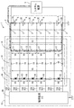
- FIG. 1 is a circuit diagram illustrating an in-vehicle battery system including a battery monitoring device according to a first embodiment.
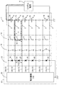
- the vehicle-mounted battery system provided with the battery monitoring apparatus of Example 1 it is explanatory drawing which shows an example in case an overvoltage is applied with respect to a battery monitoring apparatus from a system power supply.
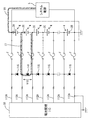
- the vehicle-mounted battery system provided with the battery monitoring apparatus of Example 1 it is explanatory drawing which shows another example in case an overvoltage is applied with respect to a battery monitoring apparatus from a system power supply.
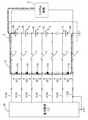
- an in-vehicle battery system of a comparative example it is explanatory drawing which shows an example in case overvoltage is applied to a battery monitoring device from a system power supply. It is explanatory drawing which shows another example in case an overvoltage is applied with respect to a battery monitoring apparatus from a system power supply in the vehicle-mounted battery system of a comparative example.
- An in-vehicle battery system 1 shown in FIG. 1 includes an in-vehicle battery module 2 (hereinafter, also referred to as a battery module 2) in which a plurality of unit batteries 4 are connected in series, and voltages at respective parts of the battery module 2.
- a battery monitoring device 10 for in-vehicle batteries to be detected (hereinafter also referred to as a battery monitoring device 10) is provided. 1 to 5, some of the unit batteries 4 are omitted, and circuits corresponding to the omitted unit batteries 4 are also omitted.
- the battery module 2 is a power storage unit that can function as an on-vehicle power source, and is mounted on the vehicle as a power source for a motor for driving an electric vehicle (EV or HEV), for example.
- the battery module 2 is configured as a series connection body in which a plurality of unit batteries 4 made of, for example, a lithium ion secondary battery or a nickel hydride secondary battery are connected in series.
- the battery module 2 can be attached to and detached from a battery monitoring device 10 to be described later.
- the end electrode portions 2A and 2B (hereinafter also referred to as electrode portions 2A and 2B) and the inter-battery electrode portion of the battery module 2 are used.
- Each terminal 3 connected to 2C (hereinafter also referred to as electrode section 2C) and each voltage signal line 12A are detachable.
- a system power supply 5 is connected to the electrode portions 2A and 2B of the battery module 2.
- the system power supply 5 is an in-vehicle power supply that can charge the battery module 2 and may be any power supply that can output power. In the example of FIG. 1, the output voltage from the system power supply 5 is applied to the electrode portions 2 ⁇ / b> A and 2 ⁇ / b> B of the battery module 2, and the unit battery 4 is charged in the battery module 2 by such power supply.
- the battery monitoring device 10 includes a protection circuit 11 and a battery monitoring IC 20 that is a monitoring circuit, and is configured as a device that monitors the battery module 2.
- the protection circuit 11 includes a signal line group 12, a first protection circuit unit 13, a second protection circuit unit 14, and a resistance unit group 15.
- the signal line group 12 includes a plurality of voltage signal lines 12A. These voltage signal lines 12A are electrically connected to the electrode portions 2A and 2B of the battery module 2 and the respective electrode portions 2C of the plurality of unit batteries 4 connected in series.
- the electrode part 2 ⁇ / b> A is an electrode part at one end of the battery module 2, and is the electrode part having the highest potential in the battery module 2.
- the electrode part 2 ⁇ / b> B is an electrode part at the other end of the battery module 2, and is the electrode part having the lowest potential in the battery module 2.
- the electrode portion 2C is a portion where the positive electrode of one unit cell 4 and the negative electrode of the other unit cell 4 are electrically connected between the unit cells 4 connected in series. Further, the potential of each of the electrode portions 2C is higher in the electrode portion 2C near the electrode portion 2A than in the electrode portion 2C far from the electrode portion 2A. Specifically, the potential of each of the plurality of electrode portions 2C increases as the position of the battery module 2 approaches the electrode portion 2A in the circuit.
- the first protection circuit unit 13 includes a plurality of Zener diodes 16 connected in series between the voltage signal line 12A having the highest potential and the voltage signal line 12A having the lowest potential. Any zener diode 16 is provided between the signal lines so that both ends thereof are connected to the two voltage signal lines 12A, respectively.
- Each of the Zener diodes 16 has a plurality of voltage signal lines 12A connected to the electrode portions 2A, 2B, and 2C, and a connection portion for the battery module 2 is connected to two voltage signal lines 12A adjacent in the circuit. Yes.
- Both voltage signal lines 12A to which both ends of the Zener diode 16 are connected (the voltage signal line 12A adjacent to the connection part for the battery module 2) has a lower potential near the electrode part 2B in the circuit, and a signal close to the electrode part 2A.
- the line has a higher potential.
- the Zener diode 16 is connected in parallel with the unit cell 4 between the signal lines of the plurality of voltage signal lines 12A connected to the electrode portions 2A, 2B, and 2C, and the anode is connected in parallel with the Zener diode 16.
- the unit battery 4 is connected to the negative voltage signal line 12A (voltage signal line having a relatively low potential), and the cathode is connected to positive voltage signal line 12A (voltage signal line having a relatively high potential). .
- Each Zener diode 16 has both ends connected to two voltage signal lines 12A, a cathode connected to a voltage signal line 12A having a relatively high potential, and a voltage signal line 12A having the next lowest potential after the voltage signal line 12A. Is connected to the anode.
- a current flows from the cathode side to the anode side of the Zener diode 16.
- the voltage between the two voltage signal lines 12A connected to both ends of the Zener diode 16 is maintained at a predetermined voltage or lower.
- the second protection circuit unit 14 includes a plurality of varistors 17 connected in series between the voltage signal line 12A having the highest potential and the voltage signal line 12A having the lowest potential. These varistors 17 are connected in parallel to the unit battery 4 between the signal lines of the plurality of voltage signal lines 12A connected to the electrode portions 2A, 2B, and 2C, and each terminal of each varistor 17 is connected to the voltage signal line. In 12A, it connects between the resistance part 19 and the unit battery 4 which are mentioned later. Any varistor 17 is provided between the signal lines so that both ends thereof are connected to the two voltage signal lines 12A, respectively.
- Each of the varistors 17 has a plurality of voltage signal lines 12A connected to the electrode portions 2A, 2B, and 2C, and a connection portion for the battery module 2 is connected to two voltage signal lines 12A adjacent in the circuit. .
- Each varistor 17 is connected in parallel to each unit battery 4 and each Zener diode 16. In any voltage signal line 12A, the connection part of the varistor 17 is between the connection part of the Zener diode 16 and the connection part of the unit cell 4.
- the varistor 17 When the voltage between the terminals of the unit battery 4 connected in parallel to the varistor 17 is increased to a predetermined value, the varistor 17 has a higher potential of the two voltage signal lines 12A connected to both ends of the varistor 17. A current flows from one voltage signal line 12A toward the other voltage signal line 12A having a low potential. Thus, the voltage between the two voltage signal lines 12A connected to both ends of the varistor 17 is maintained at a predetermined voltage or lower.
- the resistance unit group 15 includes a plurality of resistance units 19. These resistance portions 19 limit the current while being interposed between the Zener diode 16 and the unit battery 4 in each voltage signal line 12A. Specifically, in each voltage signal line 12A, a resistance portion 19 is provided between a portion to which the Zener diode 16 is connected and a portion to which the varistor 17 is connected. In the voltage signal line 12A, the current is limited so as to cause a voltage drop when the current flows from the second protection circuit unit 14 side to the first protection circuit unit 13 side.
- the battery monitoring IC 20 is connected to each of the plurality of voltage signal lines 12A in the protection circuit 11, and the voltage applied to each voltage signal line 12A is input thereto.
- the battery monitoring IC 20 detects an input voltage input via each voltage signal line 12A, and the voltage between the signal lines in the plurality of voltage signal lines 12A (that is, the voltage between the electrodes of each unit battery 4 (cell voltage). )) Respectively.
- the battery monitoring IC 20 includes a plurality of input terminals to which a plurality of voltage signal lines 12A are connected, and detects an analog voltage signal input via each voltage signal line 12A.
- the battery monitoring IC 20 may include an AD converter that converts each input analog voltage signal into a digital signal, and includes a control circuit (such as a CPU) that can perform determination and control based on each analog voltage signal. You may have.
- the plurality of unit batteries 4 constituting the battery module 2 have an equivalent configuration, and the voltage at full charge of each unit battery 4 is about a predetermined value.
- the plurality of varistors 17 have the same configuration, and all varistors 17 have the same varistor voltage.
- the plurality of Zener diodes 16 have the same configuration, and all Zener diodes 16 have the same Zener voltage. The voltage between the terminals when each unit battery 4 is fully charged is smaller than the varistor voltage of each varistor 17 and smaller than the Zener voltage of each Zener diode 16.
- the voltage between both voltage signal lines 12A connected to both ends of each unit battery 4 is within a normal range (a range lower than the voltage value (predetermined value) when the unit battery 4 is fully charged), and the entire battery module
- both voltage signal lines 12A connected to both ends are within the normal range
- the voltage between both voltage signal lines 12A connected to both ends is higher than the varistor voltage in any varistor 17. Therefore, no current flows through each varistor 17.
- the voltage between the voltage signal lines 12 ⁇ / b> A connected to both ends is smaller than the Zener voltage, so that no current flows through each Zener diode 16.
- an analog voltage signal corresponding to each voltage of the electrode portions 2A, 2B, 2C is input to the battery monitoring IC 20 via each voltage signal line 12A. Therefore, the battery monitoring IC 20 can detect the voltages of the electrode portions 2A, 2B, 2C or the voltage between the terminals of each unit battery 4 (cell voltage).
- the fuse F of the voltage signal line 112A adjacent to the voltage signal line 112A to which the blown fuse F is connected is blown, and finally. All the fuses F are blown.
- the fuse F is blown in this way, overcurrent does not flow into the circuit side where the battery monitoring IC and the Zener diode 116 are provided, but the battery monitoring IC 20 cannot detect the voltage at each part of the battery module 2. For this reason, in the battery system of FIG. 4, if the fuse F is blown, even if the overvoltage output state of the system power supply 5 can be eliminated, it cannot be operated unless the fuse F is replaced.
- an overvoltage is output from the system power supply 5, and the voltage signal line 12A connected to the electrode part 2A and the voltage signal line 12A connected to the electrode part 2B are output.
- the voltage V4 between the terminals of the plurality of varistors 17 connected in series between the voltage signal lines 12A on both sides increases.
- the inter-terminal voltage V4 of each varistor 17 becomes larger than the varistor voltage of each varistor 17, a current I2 flows from the electrode part 2A side to the electrode part 2B side via each varistor 17, and the voltage across each varistor 17 is a predetermined voltage. Clamped to about voltage.
- the battery monitoring device 10 is configured such that the potential difference between the voltage signal line 12A connected to the electrode part 2A and the voltage signal line 12A connected to the electrode part 2B is generated by the overvoltage being output from the system power supply 5.
- it can suppress that an electric current flows into both the path
- the current in the direction from the varistor 17 side to the Zener diode 16 side is limited due to the presence of each resistance unit 19 arranged in each voltage signal line 12A.
- the voltage across the path V5 of the path where the Zener diode 16 is connected in series is smaller than the voltage V3 of the path where the varistor 17 is connected in series, and is applied to each Zener diode 16 when an overvoltage occurs. Voltage is suppressed.
- route where the Zener diode 16 was connected in series at least can be suppressed.
- a larger current can flow in the path in which the varistor 17 is connected in series, and the current I3 in the path in which the Zener diode 16 is connected in series is It can be made smaller than the current I2 of the path of the varistor 17.
- the variation between the individual clamp voltages of each Zener diode 16 is smaller than the variation between the individual clamp voltages of each varistor 17.
- the clamp voltage of each Zener diode 16 can be kept near a constant value while suppressing variations. Therefore, it is possible to prevent the potential difference between adjacent input terminals in the battery monitoring IC 20 from increasing due to variations.
- any of the electrode portions 2A, 2B, and 2C is generated when a state where the output voltage from the system power supply 5 becomes larger than the normal range (overvoltage output state) occurs.
- the operation of the battery monitoring device 10 when there is an open failure will be described.
- a current I7 flows through the Zener diode 116, and the voltage between both ends is clamped to the magnitude of the Zener voltage.
- the current I7 exceeds the rated current of the fuse F and reaches the fusing current, the fuse F is blown. In this case as well, voltage cannot be detected through the blown path unless the fuse F is replaced.
- the battery monitoring apparatus 10 of the first embodiment has a part of the unit batteries 4 to be connected in series when an overvoltage is output from the system power supply 5 (example of FIG. 3).
- the varistor 17 and the Zener diode 16 are connected by avoiding the open failure position as shown in FIG. Overcurrent flows to pass.
- the voltage V11 across the varistor 17 and the voltage V12 across the Zener diode 16 arranged in parallel with the unit battery 4 that has failed due to an overvoltage increase as the overvoltage occurs.
- the protection circuit 11 sends a current to the varistor 17 disposed between the voltage signal lines. It is possible to prevent an overcurrent from flowing into the battery monitoring IC (monitoring circuit) side. Since current can flow through the varistor 17 in this way, the current flowing through the Zener diode 16 can be suppressed to a smaller value than when no varistor 17 is present. When a part of the current flows through the Zener diode 16 when an overcurrent occurs, the voltage between the voltage signal lines can be clamped by the Zener diode 16.
- the voltage between the voltage signal lines can be clamped with the accuracy of the Zener diode 16 on the battery monitoring IC (monitoring circuit) side of the varistor 17. That is, even if the clamping accuracy of the varistor 17 varies, it is possible to clamp with the accuracy of the Zener diode 16 on the Zener diode 16 side.
- the present invention is not limited to the embodiments described with reference to the above description and drawings. For example, the following embodiments are also included in the technical scope of the present invention.
- the number of unit batteries constituting the battery module may be plural, and the number is not limited.
- the number of voltage signal lines connected to each part of the battery module may be plural, and the number is not limited.
- the configuration in which the voltage signal line 12A is connected to the electrode portions 2A and 2B and the electrode portion 2C of the battery module 2 is illustrated.
- the end electrode portions of the battery module and all the inter-battery electrode portions may not be connected to any one or a plurality of positions.
- a plurality of voltage signal lines may be connected to each of the unit batteries 4 connected in series.
- secondary batteries such as nickel metal hydride batteries and lithium ion batteries are exemplified as the unit batteries 4, but power storage means such as electric double layer capacitors may be used instead of these secondary batteries.
- the battery monitoring device may include a battery module. That is, the battery monitoring device may or may not include a battery module as a component.
- the battery monitoring device includes a battery module as a component, for example, a circuit configuration body in which a Zener diode, a voltage signal line, and the like are provided on a substrate, and the battery module may be configured integrally.
- one battery monitoring device 10 monitors each part of one battery module 2
- a plurality of battery modules are monitored.
- the battery monitoring device may be provided, and the battery monitoring device may be provided so as to correspond to each battery module.
- a plurality of battery modules 2 may be connected in series, and an output voltage may be applied from the system power supply to the plurality of battery modules 2 connected in series.
- one battery monitoring device may be connected to each battery module 2, or one battery monitoring device may be assigned to a plurality of battery modules 2.
- a plurality of battery monitoring devices may be assigned to each battery module 2.
Landscapes
- Engineering & Computer Science (AREA)
- Physics & Mathematics (AREA)
- General Physics & Mathematics (AREA)
- Manufacturing & Machinery (AREA)
- Chemical & Material Sciences (AREA)
- Chemical Kinetics & Catalysis (AREA)
- Electrochemistry (AREA)
- General Chemical & Material Sciences (AREA)
- Power Engineering (AREA)
- Secondary Cells (AREA)
- Charge And Discharge Circuits For Batteries Or The Like (AREA)
- Emergency Protection Circuit Devices (AREA)
Priority Applications (2)
| Application Number | Priority Date | Filing Date | Title |
|---|---|---|---|
| US16/467,344 US11079439B2 (en) | 2016-12-07 | 2017-11-16 | Protection circuit for battery monitoring device, and battery monitoring device |
| CN201780074182.9A CN110140274A (zh) | 2016-12-07 | 2017-11-16 | 电池监视装置的保护电路及电池监视装置 |
Applications Claiming Priority (2)
| Application Number | Priority Date | Filing Date | Title |
|---|---|---|---|
| JP2016237263A JP6774628B2 (ja) | 2016-12-07 | 2016-12-07 | 電池監視装置の保護回路、及び電池監視装置 |
| JP2016-237263 | 2016-12-07 |
Publications (1)
| Publication Number | Publication Date |
|---|---|
| WO2018105342A1 true WO2018105342A1 (ja) | 2018-06-14 |
Family
ID=62492018
Family Applications (1)
| Application Number | Title | Priority Date | Filing Date |
|---|---|---|---|
| PCT/JP2017/041172 Ceased WO2018105342A1 (ja) | 2016-12-07 | 2017-11-16 | 電池監視装置の保護回路、及び電池監視装置 |
Country Status (4)
| Country | Link |
|---|---|
| US (1) | US11079439B2 (enExample) |
| JP (1) | JP6774628B2 (enExample) |
| CN (1) | CN110140274A (enExample) |
| WO (1) | WO2018105342A1 (enExample) |
Families Citing this family (5)
| Publication number | Priority date | Publication date | Assignee | Title |
|---|---|---|---|---|
| WO2018051574A1 (ja) * | 2016-09-13 | 2018-03-22 | 三洋電機株式会社 | 管理装置および電源システム |
| CN108879618B (zh) * | 2018-07-20 | 2020-05-08 | 坎德拉(深圳)科技创新有限公司 | 一种电池保护电路和多电平电池保护电路 |
| CN109742743A (zh) * | 2018-12-03 | 2019-05-10 | 欣旺达电子股份有限公司 | 宽范围高电压采样钳位保护电路 |
| KR102757430B1 (ko) | 2019-12-05 | 2025-01-17 | 주식회사 엘지에너지솔루션 | 복수의 전류 경로를 포함하는 배터리 팩 |
| DE102023113205A1 (de) * | 2023-05-19 | 2024-11-21 | EA Elektro-Automatik GmbH & Co. KG | Vorrichtung zum Testen eines elektrischen Energiespeichers |
Citations (4)
| Publication number | Priority date | Publication date | Assignee | Title |
|---|---|---|---|---|
| JPS59122733U (ja) * | 1983-02-08 | 1984-08-18 | 村田 茂 | 避雷器 |
| JP3150369U (ja) * | 2009-02-26 | 2009-05-07 | アクソンデータマシン株式会社 | 自動車用のサージ抑制装置 |
| JP2010057265A (ja) * | 2008-08-28 | 2010-03-11 | Toyota Motor Corp | 組電池および組電池の制御システム |
| JP2014090635A (ja) * | 2012-10-31 | 2014-05-15 | Toyota Motor Corp | 蓄電システム |
Family Cites Families (5)
| Publication number | Priority date | Publication date | Assignee | Title |
|---|---|---|---|---|
| CN101465436A (zh) * | 2007-12-17 | 2009-06-24 | 汉能科技有限公司 | 燃料电池系统手动启动装置 |
| JP2013106442A (ja) * | 2011-11-14 | 2013-05-30 | Sanyo Electric Co Ltd | パック電池の検査方法及びパック電池 |
| JP2013121246A (ja) | 2011-12-07 | 2013-06-17 | Panasonic Corp | 電池モジュール及び電池システム |
| JP5585616B2 (ja) * | 2012-06-26 | 2014-09-10 | 株式会社デンソー | 回路保護装置 |
| CN102841301A (zh) * | 2012-09-27 | 2012-12-26 | 常州旭能新能源科技有限公司 | 一种光伏组件监测系统 |
-
2016
- 2016-12-07 JP JP2016237263A patent/JP6774628B2/ja not_active Expired - Fee Related
-
2017
- 2017-11-16 CN CN201780074182.9A patent/CN110140274A/zh active Pending
- 2017-11-16 US US16/467,344 patent/US11079439B2/en not_active Expired - Fee Related
- 2017-11-16 WO PCT/JP2017/041172 patent/WO2018105342A1/ja not_active Ceased
Patent Citations (4)
| Publication number | Priority date | Publication date | Assignee | Title |
|---|---|---|---|---|
| JPS59122733U (ja) * | 1983-02-08 | 1984-08-18 | 村田 茂 | 避雷器 |
| JP2010057265A (ja) * | 2008-08-28 | 2010-03-11 | Toyota Motor Corp | 組電池および組電池の制御システム |
| JP3150369U (ja) * | 2009-02-26 | 2009-05-07 | アクソンデータマシン株式会社 | 自動車用のサージ抑制装置 |
| JP2014090635A (ja) * | 2012-10-31 | 2014-05-15 | Toyota Motor Corp | 蓄電システム |
Also Published As
| Publication number | Publication date |
|---|---|
| US11079439B2 (en) | 2021-08-03 |
| US20190324091A1 (en) | 2019-10-24 |
| JP6774628B2 (ja) | 2020-10-28 |
| CN110140274A (zh) | 2019-08-16 |
| JP2018093679A (ja) | 2018-06-14 |
Similar Documents
| Publication | Publication Date | Title |
|---|---|---|
| WO2018105342A1 (ja) | 電池監視装置の保護回路、及び電池監視装置 | |
| JP6642384B2 (ja) | 車載電池用の電池監視装置 | |
| US20130149572A1 (en) | Battery unit | |
| CN110780206B (zh) | 电池监视设备 | |
| CN109247036B (zh) | 管理装置和电源系统 | |
| JP2014169913A (ja) | 組電池の電圧検出装置 | |
| JP2014225950A (ja) | 蓄電システム | |
| US11121411B2 (en) | Battery pack and method for detecting whether or not busbar is opened using the battery pack | |
| US20240131963A1 (en) | On-board switching device | |
| JP5750739B2 (ja) | 二次電池の保護回路 | |
| US10495695B2 (en) | Abnormality detecting device for a system including battery assemblies | |
| JP2014048281A (ja) | 電源装置および故障検出回路 | |
| JP6229668B2 (ja) | 蓄電システム | |
| JP2018007392A (ja) | 組電池の電圧検出装置 | |
| JP6014764B2 (ja) | 電池システム監視装置 | |
| JP6789768B2 (ja) | 回路保護装置及び電源監視装置 | |
| US20200152947A1 (en) | Battery System Monitoring Device and Battery Pack | |
| JP2022062882A (ja) | 組電池の監視装置 | |
| JP2019161702A (ja) | 回路保護装置及び電源監視装置 | |
| JP2021163642A (ja) | 電池システムおよび検知方法 | |
| JP2018190677A (ja) | 回路保護装置 | |
| JP2021090235A (ja) | 蓄電システム | |
| WO2018021059A1 (ja) | 車載電池用の電圧検出回路 | |
| JP2015210166A (ja) | 電池監視装置 |
Legal Events
| Date | Code | Title | Description |
|---|---|---|---|
| 121 | Ep: the epo has been informed by wipo that ep was designated in this application |
Ref document number: 17877684 Country of ref document: EP Kind code of ref document: A1 |
|
| NENP | Non-entry into the national phase |
Ref country code: DE |
|
| 122 | Ep: pct application non-entry in european phase |
Ref document number: 17877684 Country of ref document: EP Kind code of ref document: A1 |