WO2018105342A1 - Battery monitoring device protection circuit and battery monitoring device - Google Patents
Battery monitoring device protection circuit and battery monitoring device Download PDFInfo
- Publication number
- WO2018105342A1 WO2018105342A1 PCT/JP2017/041172 JP2017041172W WO2018105342A1 WO 2018105342 A1 WO2018105342 A1 WO 2018105342A1 JP 2017041172 W JP2017041172 W JP 2017041172W WO 2018105342 A1 WO2018105342 A1 WO 2018105342A1
- Authority
- WO
- WIPO (PCT)
- Prior art keywords
- voltage signal
- voltage
- battery
- signal lines
- unit
- Prior art date
Links
Images

Classifications
-
- G—PHYSICS
- G01—MEASURING; TESTING
- G01R—MEASURING ELECTRIC VARIABLES; MEASURING MAGNETIC VARIABLES
- G01R1/00—Details of instruments or arrangements of the types included in groups G01R5/00 - G01R13/00 and G01R31/00
- G01R1/36—Overload-protection arrangements or circuits for electric measuring instruments
-
- G—PHYSICS
- G01—MEASURING; TESTING
- G01R—MEASURING ELECTRIC VARIABLES; MEASURING MAGNETIC VARIABLES
- G01R31/00—Arrangements for testing electric properties; Arrangements for locating electric faults; Arrangements for electrical testing characterised by what is being tested not provided for elsewhere
- G01R31/36—Arrangements for testing, measuring or monitoring the electrical condition of accumulators or electric batteries, e.g. capacity or state of charge [SoC]
- G01R31/382—Arrangements for monitoring battery or accumulator variables, e.g. SoC
- G01R31/3835—Arrangements for monitoring battery or accumulator variables, e.g. SoC involving only voltage measurements
-
- H—ELECTRICITY
- H01—ELECTRIC ELEMENTS
- H01M—PROCESSES OR MEANS, e.g. BATTERIES, FOR THE DIRECT CONVERSION OF CHEMICAL ENERGY INTO ELECTRICAL ENERGY
- H01M10/00—Secondary cells; Manufacture thereof
- H01M10/42—Methods or arrangements for servicing or maintenance of secondary cells or secondary half-cells
- H01M10/48—Accumulators combined with arrangements for measuring, testing or indicating the condition of cells, e.g. the level or density of the electrolyte
- H01M10/482—Accumulators combined with arrangements for measuring, testing or indicating the condition of cells, e.g. the level or density of the electrolyte for several batteries or cells simultaneously or sequentially
-
- H—ELECTRICITY
- H02—GENERATION; CONVERSION OR DISTRIBUTION OF ELECTRIC POWER
- H02H—EMERGENCY PROTECTIVE CIRCUIT ARRANGEMENTS
- H02H9/00—Emergency protective circuit arrangements for limiting excess current or voltage without disconnection
- H02H9/04—Emergency protective circuit arrangements for limiting excess current or voltage without disconnection responsive to excess voltage
- H02H9/045—Emergency protective circuit arrangements for limiting excess current or voltage without disconnection responsive to excess voltage adapted to a particular application and not provided for elsewhere
-
- H—ELECTRICITY
- H02—GENERATION; CONVERSION OR DISTRIBUTION OF ELECTRIC POWER
- H02J—CIRCUIT ARRANGEMENTS OR SYSTEMS FOR SUPPLYING OR DISTRIBUTING ELECTRIC POWER; SYSTEMS FOR STORING ELECTRIC ENERGY
- H02J7/00—Circuit arrangements for charging or depolarising batteries or for supplying loads from batteries
- H02J7/0013—Circuit arrangements for charging or depolarising batteries or for supplying loads from batteries acting upon several batteries simultaneously or sequentially
-
- H—ELECTRICITY
- H02—GENERATION; CONVERSION OR DISTRIBUTION OF ELECTRIC POWER
- H02J—CIRCUIT ARRANGEMENTS OR SYSTEMS FOR SUPPLYING OR DISTRIBUTING ELECTRIC POWER; SYSTEMS FOR STORING ELECTRIC ENERGY
- H02J7/00—Circuit arrangements for charging or depolarising batteries or for supplying loads from batteries
- H02J7/0047—Circuit arrangements for charging or depolarising batteries or for supplying loads from batteries with monitoring or indicating devices or circuits
-
- G—PHYSICS
- G01—MEASURING; TESTING
- G01R—MEASURING ELECTRIC VARIABLES; MEASURING MAGNETIC VARIABLES
- G01R31/00—Arrangements for testing electric properties; Arrangements for locating electric faults; Arrangements for electrical testing characterised by what is being tested not provided for elsewhere
- G01R31/36—Arrangements for testing, measuring or monitoring the electrical condition of accumulators or electric batteries, e.g. capacity or state of charge [SoC]
- G01R31/396—Acquisition or processing of data for testing or for monitoring individual cells or groups of cells within a battery
-
- H—ELECTRICITY
- H01—ELECTRIC ELEMENTS
- H01M—PROCESSES OR MEANS, e.g. BATTERIES, FOR THE DIRECT CONVERSION OF CHEMICAL ENERGY INTO ELECTRICAL ENERGY
- H01M2200/00—Safety devices for primary or secondary batteries
-
- H—ELECTRICITY
- H01—ELECTRIC ELEMENTS
- H01M—PROCESSES OR MEANS, e.g. BATTERIES, FOR THE DIRECT CONVERSION OF CHEMICAL ENERGY INTO ELECTRICAL ENERGY
- H01M2220/00—Batteries for particular applications
- H01M2220/20—Batteries in motive systems, e.g. vehicle, ship, plane
-
- Y—GENERAL TAGGING OF NEW TECHNOLOGICAL DEVELOPMENTS; GENERAL TAGGING OF CROSS-SECTIONAL TECHNOLOGIES SPANNING OVER SEVERAL SECTIONS OF THE IPC; TECHNICAL SUBJECTS COVERED BY FORMER USPC CROSS-REFERENCE ART COLLECTIONS [XRACs] AND DIGESTS
- Y02—TECHNOLOGIES OR APPLICATIONS FOR MITIGATION OR ADAPTATION AGAINST CLIMATE CHANGE
- Y02E—REDUCTION OF GREENHOUSE GAS [GHG] EMISSIONS, RELATED TO ENERGY GENERATION, TRANSMISSION OR DISTRIBUTION
- Y02E60/00—Enabling technologies; Technologies with a potential or indirect contribution to GHG emissions mitigation
- Y02E60/10—Energy storage using batteries
-
- Y—GENERAL TAGGING OF NEW TECHNOLOGICAL DEVELOPMENTS; GENERAL TAGGING OF CROSS-SECTIONAL TECHNOLOGIES SPANNING OVER SEVERAL SECTIONS OF THE IPC; TECHNICAL SUBJECTS COVERED BY FORMER USPC CROSS-REFERENCE ART COLLECTIONS [XRACs] AND DIGESTS
- Y02—TECHNOLOGIES OR APPLICATIONS FOR MITIGATION OR ADAPTATION AGAINST CLIMATE CHANGE
- Y02T—CLIMATE CHANGE MITIGATION TECHNOLOGIES RELATED TO TRANSPORTATION
- Y02T10/00—Road transport of goods or passengers
- Y02T10/60—Other road transportation technologies with climate change mitigation effect
- Y02T10/70—Energy storage systems for electromobility, e.g. batteries
Definitions
- the present invention relates to a protection circuit for a battery monitoring device and a battery monitoring device.
- Patent Literature 1 discloses an example of a battery system in which the voltage measurement unit monitors the voltage of each battery cell via a voltage measurement line.
- a voltage higher than usual is applied to the battery module, a current flows through the zener diode via the fuse provided in the voltage measurement line, and the fuse is blown. The circuit is protected by such a blow of the fuse.
- the present invention has been made based on the above-described circumstances, and an object of the present invention is to provide a battery monitoring device protection circuit and a battery monitoring device that can protect a circuit from overcurrent without fusing a path. is there.
- the first invention is A protection circuit for a battery monitoring device that monitors a battery module having a configuration in which a plurality of unit batteries are connected in series, A plurality of voltage signal lines, and a signal line group in which each of the voltage signal lines is electrically connected to an inter-battery electrode portion of the plurality of unit cells connected in series or an end electrode portion of the battery module; , A plurality of zener diodes connected in series, each zener diode being connected in parallel with the unit cell between the signal lines of the plurality of voltage signal lines, and the anode of each zener diode being in parallel; A first protection circuit unit connected to the voltage signal line on the negative electrode side of the unit battery connected to the cathode, and having a cathode connected to the voltage signal line on the positive electrode side; A plurality of resistor units, each resistor unit being a resistor unit group that limits current while being interposed between the Zener diode and the unit cell in each voltage signal line; A plurality of varistors connected in
- the battery monitoring device is the protection circuit, the monitoring circuit that is connected to each of the plurality of voltage signal lines in the protection circuit, and that receives the voltage applied to each of the voltage signal lines, including.
- the first invention when an overvoltage occurs in the whole or a part of the battery module and a potential difference between any of the voltage signal lines becomes large, a current is supplied to the varistor disposed between the voltage signal lines. , Overcurrent can be prevented from flowing into the monitoring circuit side. Since current can flow through the varistor in this way, the current flowing through the Zener diode can be suppressed to be smaller than when no varistor is present.
- the voltage between the voltage signal lines can be clamped by the Zener diode. At this time, the voltage between the voltage signal lines can be clamped with the accuracy of the Zener diode on the monitoring circuit side from the varistor. That is, even if the clamping accuracy of the varistor varies, the Zener diode can be clamped with the accuracy of the Zener diode.
- the second invention it is possible to realize a battery monitoring device that exhibits the same effects as the first invention.
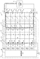
- FIG. 1 is a circuit diagram illustrating an in-vehicle battery system including a battery monitoring device according to a first embodiment.
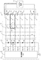
- the vehicle-mounted battery system provided with the battery monitoring apparatus of Example 1 it is explanatory drawing which shows an example in case an overvoltage is applied with respect to a battery monitoring apparatus from a system power supply.
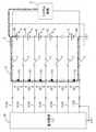
- the vehicle-mounted battery system provided with the battery monitoring apparatus of Example 1 it is explanatory drawing which shows another example in case an overvoltage is applied with respect to a battery monitoring apparatus from a system power supply.
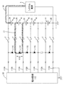
- an in-vehicle battery system of a comparative example it is explanatory drawing which shows an example in case overvoltage is applied to a battery monitoring device from a system power supply. It is explanatory drawing which shows another example in case an overvoltage is applied with respect to a battery monitoring apparatus from a system power supply in the vehicle-mounted battery system of a comparative example.
- An in-vehicle battery system 1 shown in FIG. 1 includes an in-vehicle battery module 2 (hereinafter, also referred to as a battery module 2) in which a plurality of unit batteries 4 are connected in series, and voltages at respective parts of the battery module 2.
- a battery monitoring device 10 for in-vehicle batteries to be detected (hereinafter also referred to as a battery monitoring device 10) is provided. 1 to 5, some of the unit batteries 4 are omitted, and circuits corresponding to the omitted unit batteries 4 are also omitted.
- the battery module 2 is a power storage unit that can function as an on-vehicle power source, and is mounted on the vehicle as a power source for a motor for driving an electric vehicle (EV or HEV), for example.
- the battery module 2 is configured as a series connection body in which a plurality of unit batteries 4 made of, for example, a lithium ion secondary battery or a nickel hydride secondary battery are connected in series.
- the battery module 2 can be attached to and detached from a battery monitoring device 10 to be described later.
- the end electrode portions 2A and 2B (hereinafter also referred to as electrode portions 2A and 2B) and the inter-battery electrode portion of the battery module 2 are used.
- Each terminal 3 connected to 2C (hereinafter also referred to as electrode section 2C) and each voltage signal line 12A are detachable.
- a system power supply 5 is connected to the electrode portions 2A and 2B of the battery module 2.
- the system power supply 5 is an in-vehicle power supply that can charge the battery module 2 and may be any power supply that can output power. In the example of FIG. 1, the output voltage from the system power supply 5 is applied to the electrode portions 2 ⁇ / b> A and 2 ⁇ / b> B of the battery module 2, and the unit battery 4 is charged in the battery module 2 by such power supply.
- the battery monitoring device 10 includes a protection circuit 11 and a battery monitoring IC 20 that is a monitoring circuit, and is configured as a device that monitors the battery module 2.
- the protection circuit 11 includes a signal line group 12, a first protection circuit unit 13, a second protection circuit unit 14, and a resistance unit group 15.
- the signal line group 12 includes a plurality of voltage signal lines 12A. These voltage signal lines 12A are electrically connected to the electrode portions 2A and 2B of the battery module 2 and the respective electrode portions 2C of the plurality of unit batteries 4 connected in series.
- the electrode part 2 ⁇ / b> A is an electrode part at one end of the battery module 2, and is the electrode part having the highest potential in the battery module 2.
- the electrode part 2 ⁇ / b> B is an electrode part at the other end of the battery module 2, and is the electrode part having the lowest potential in the battery module 2.
- the electrode portion 2C is a portion where the positive electrode of one unit cell 4 and the negative electrode of the other unit cell 4 are electrically connected between the unit cells 4 connected in series. Further, the potential of each of the electrode portions 2C is higher in the electrode portion 2C near the electrode portion 2A than in the electrode portion 2C far from the electrode portion 2A. Specifically, the potential of each of the plurality of electrode portions 2C increases as the position of the battery module 2 approaches the electrode portion 2A in the circuit.
- the first protection circuit unit 13 includes a plurality of Zener diodes 16 connected in series between the voltage signal line 12A having the highest potential and the voltage signal line 12A having the lowest potential. Any zener diode 16 is provided between the signal lines so that both ends thereof are connected to the two voltage signal lines 12A, respectively.
- Each of the Zener diodes 16 has a plurality of voltage signal lines 12A connected to the electrode portions 2A, 2B, and 2C, and a connection portion for the battery module 2 is connected to two voltage signal lines 12A adjacent in the circuit. Yes.
- Both voltage signal lines 12A to which both ends of the Zener diode 16 are connected (the voltage signal line 12A adjacent to the connection part for the battery module 2) has a lower potential near the electrode part 2B in the circuit, and a signal close to the electrode part 2A.
- the line has a higher potential.
- the Zener diode 16 is connected in parallel with the unit cell 4 between the signal lines of the plurality of voltage signal lines 12A connected to the electrode portions 2A, 2B, and 2C, and the anode is connected in parallel with the Zener diode 16.
- the unit battery 4 is connected to the negative voltage signal line 12A (voltage signal line having a relatively low potential), and the cathode is connected to positive voltage signal line 12A (voltage signal line having a relatively high potential). .
- Each Zener diode 16 has both ends connected to two voltage signal lines 12A, a cathode connected to a voltage signal line 12A having a relatively high potential, and a voltage signal line 12A having the next lowest potential after the voltage signal line 12A. Is connected to the anode.
- a current flows from the cathode side to the anode side of the Zener diode 16.
- the voltage between the two voltage signal lines 12A connected to both ends of the Zener diode 16 is maintained at a predetermined voltage or lower.
- the second protection circuit unit 14 includes a plurality of varistors 17 connected in series between the voltage signal line 12A having the highest potential and the voltage signal line 12A having the lowest potential. These varistors 17 are connected in parallel to the unit battery 4 between the signal lines of the plurality of voltage signal lines 12A connected to the electrode portions 2A, 2B, and 2C, and each terminal of each varistor 17 is connected to the voltage signal line. In 12A, it connects between the resistance part 19 and the unit battery 4 which are mentioned later. Any varistor 17 is provided between the signal lines so that both ends thereof are connected to the two voltage signal lines 12A, respectively.
- Each of the varistors 17 has a plurality of voltage signal lines 12A connected to the electrode portions 2A, 2B, and 2C, and a connection portion for the battery module 2 is connected to two voltage signal lines 12A adjacent in the circuit. .
- Each varistor 17 is connected in parallel to each unit battery 4 and each Zener diode 16. In any voltage signal line 12A, the connection part of the varistor 17 is between the connection part of the Zener diode 16 and the connection part of the unit cell 4.
- the varistor 17 When the voltage between the terminals of the unit battery 4 connected in parallel to the varistor 17 is increased to a predetermined value, the varistor 17 has a higher potential of the two voltage signal lines 12A connected to both ends of the varistor 17. A current flows from one voltage signal line 12A toward the other voltage signal line 12A having a low potential. Thus, the voltage between the two voltage signal lines 12A connected to both ends of the varistor 17 is maintained at a predetermined voltage or lower.
- the resistance unit group 15 includes a plurality of resistance units 19. These resistance portions 19 limit the current while being interposed between the Zener diode 16 and the unit battery 4 in each voltage signal line 12A. Specifically, in each voltage signal line 12A, a resistance portion 19 is provided between a portion to which the Zener diode 16 is connected and a portion to which the varistor 17 is connected. In the voltage signal line 12A, the current is limited so as to cause a voltage drop when the current flows from the second protection circuit unit 14 side to the first protection circuit unit 13 side.
- the battery monitoring IC 20 is connected to each of the plurality of voltage signal lines 12A in the protection circuit 11, and the voltage applied to each voltage signal line 12A is input thereto.
- the battery monitoring IC 20 detects an input voltage input via each voltage signal line 12A, and the voltage between the signal lines in the plurality of voltage signal lines 12A (that is, the voltage between the electrodes of each unit battery 4 (cell voltage). )) Respectively.
- the battery monitoring IC 20 includes a plurality of input terminals to which a plurality of voltage signal lines 12A are connected, and detects an analog voltage signal input via each voltage signal line 12A.
- the battery monitoring IC 20 may include an AD converter that converts each input analog voltage signal into a digital signal, and includes a control circuit (such as a CPU) that can perform determination and control based on each analog voltage signal. You may have.
- the plurality of unit batteries 4 constituting the battery module 2 have an equivalent configuration, and the voltage at full charge of each unit battery 4 is about a predetermined value.
- the plurality of varistors 17 have the same configuration, and all varistors 17 have the same varistor voltage.
- the plurality of Zener diodes 16 have the same configuration, and all Zener diodes 16 have the same Zener voltage. The voltage between the terminals when each unit battery 4 is fully charged is smaller than the varistor voltage of each varistor 17 and smaller than the Zener voltage of each Zener diode 16.
- the voltage between both voltage signal lines 12A connected to both ends of each unit battery 4 is within a normal range (a range lower than the voltage value (predetermined value) when the unit battery 4 is fully charged), and the entire battery module
- both voltage signal lines 12A connected to both ends are within the normal range
- the voltage between both voltage signal lines 12A connected to both ends is higher than the varistor voltage in any varistor 17. Therefore, no current flows through each varistor 17.
- the voltage between the voltage signal lines 12 ⁇ / b> A connected to both ends is smaller than the Zener voltage, so that no current flows through each Zener diode 16.
- an analog voltage signal corresponding to each voltage of the electrode portions 2A, 2B, 2C is input to the battery monitoring IC 20 via each voltage signal line 12A. Therefore, the battery monitoring IC 20 can detect the voltages of the electrode portions 2A, 2B, 2C or the voltage between the terminals of each unit battery 4 (cell voltage).
- the fuse F of the voltage signal line 112A adjacent to the voltage signal line 112A to which the blown fuse F is connected is blown, and finally. All the fuses F are blown.
- the fuse F is blown in this way, overcurrent does not flow into the circuit side where the battery monitoring IC and the Zener diode 116 are provided, but the battery monitoring IC 20 cannot detect the voltage at each part of the battery module 2. For this reason, in the battery system of FIG. 4, if the fuse F is blown, even if the overvoltage output state of the system power supply 5 can be eliminated, it cannot be operated unless the fuse F is replaced.
- an overvoltage is output from the system power supply 5, and the voltage signal line 12A connected to the electrode part 2A and the voltage signal line 12A connected to the electrode part 2B are output.
- the voltage V4 between the terminals of the plurality of varistors 17 connected in series between the voltage signal lines 12A on both sides increases.
- the inter-terminal voltage V4 of each varistor 17 becomes larger than the varistor voltage of each varistor 17, a current I2 flows from the electrode part 2A side to the electrode part 2B side via each varistor 17, and the voltage across each varistor 17 is a predetermined voltage. Clamped to about voltage.
- the battery monitoring device 10 is configured such that the potential difference between the voltage signal line 12A connected to the electrode part 2A and the voltage signal line 12A connected to the electrode part 2B is generated by the overvoltage being output from the system power supply 5.
- it can suppress that an electric current flows into both the path
- the current in the direction from the varistor 17 side to the Zener diode 16 side is limited due to the presence of each resistance unit 19 arranged in each voltage signal line 12A.
- the voltage across the path V5 of the path where the Zener diode 16 is connected in series is smaller than the voltage V3 of the path where the varistor 17 is connected in series, and is applied to each Zener diode 16 when an overvoltage occurs. Voltage is suppressed.
- route where the Zener diode 16 was connected in series at least can be suppressed.
- a larger current can flow in the path in which the varistor 17 is connected in series, and the current I3 in the path in which the Zener diode 16 is connected in series is It can be made smaller than the current I2 of the path of the varistor 17.
- the variation between the individual clamp voltages of each Zener diode 16 is smaller than the variation between the individual clamp voltages of each varistor 17.
- the clamp voltage of each Zener diode 16 can be kept near a constant value while suppressing variations. Therefore, it is possible to prevent the potential difference between adjacent input terminals in the battery monitoring IC 20 from increasing due to variations.
- any of the electrode portions 2A, 2B, and 2C is generated when a state where the output voltage from the system power supply 5 becomes larger than the normal range (overvoltage output state) occurs.
- the operation of the battery monitoring device 10 when there is an open failure will be described.
- a current I7 flows through the Zener diode 116, and the voltage between both ends is clamped to the magnitude of the Zener voltage.
- the current I7 exceeds the rated current of the fuse F and reaches the fusing current, the fuse F is blown. In this case as well, voltage cannot be detected through the blown path unless the fuse F is replaced.
- the battery monitoring apparatus 10 of the first embodiment has a part of the unit batteries 4 to be connected in series when an overvoltage is output from the system power supply 5 (example of FIG. 3).
- the varistor 17 and the Zener diode 16 are connected by avoiding the open failure position as shown in FIG. Overcurrent flows to pass.
- the voltage V11 across the varistor 17 and the voltage V12 across the Zener diode 16 arranged in parallel with the unit battery 4 that has failed due to an overvoltage increase as the overvoltage occurs.
- the protection circuit 11 sends a current to the varistor 17 disposed between the voltage signal lines. It is possible to prevent an overcurrent from flowing into the battery monitoring IC (monitoring circuit) side. Since current can flow through the varistor 17 in this way, the current flowing through the Zener diode 16 can be suppressed to a smaller value than when no varistor 17 is present. When a part of the current flows through the Zener diode 16 when an overcurrent occurs, the voltage between the voltage signal lines can be clamped by the Zener diode 16.
- the voltage between the voltage signal lines can be clamped with the accuracy of the Zener diode 16 on the battery monitoring IC (monitoring circuit) side of the varistor 17. That is, even if the clamping accuracy of the varistor 17 varies, it is possible to clamp with the accuracy of the Zener diode 16 on the Zener diode 16 side.
- the present invention is not limited to the embodiments described with reference to the above description and drawings. For example, the following embodiments are also included in the technical scope of the present invention.
- the number of unit batteries constituting the battery module may be plural, and the number is not limited.
- the number of voltage signal lines connected to each part of the battery module may be plural, and the number is not limited.
- the configuration in which the voltage signal line 12A is connected to the electrode portions 2A and 2B and the electrode portion 2C of the battery module 2 is illustrated.
- the end electrode portions of the battery module and all the inter-battery electrode portions may not be connected to any one or a plurality of positions.
- a plurality of voltage signal lines may be connected to each of the unit batteries 4 connected in series.
- secondary batteries such as nickel metal hydride batteries and lithium ion batteries are exemplified as the unit batteries 4, but power storage means such as electric double layer capacitors may be used instead of these secondary batteries.
- the battery monitoring device may include a battery module. That is, the battery monitoring device may or may not include a battery module as a component.
- the battery monitoring device includes a battery module as a component, for example, a circuit configuration body in which a Zener diode, a voltage signal line, and the like are provided on a substrate, and the battery module may be configured integrally.
- one battery monitoring device 10 monitors each part of one battery module 2
- a plurality of battery modules are monitored.
- the battery monitoring device may be provided, and the battery monitoring device may be provided so as to correspond to each battery module.
- a plurality of battery modules 2 may be connected in series, and an output voltage may be applied from the system power supply to the plurality of battery modules 2 connected in series.
- one battery monitoring device may be connected to each battery module 2, or one battery monitoring device may be assigned to a plurality of battery modules 2.
- a plurality of battery monitoring devices may be assigned to each battery module 2.
Abstract
A protection circuit for a battery monitoring device for monitoring a battery module protects a circuit from overcurrent without blowing out a path. A signal line group (12) of the protection circuit (11) comprises a plurality of voltage signal lines (12A), wherein the voltage signal lines (12A) are connected to the electrode portions (2C) of a plurality of unit batteries (4) or the electrode portions (2A, 2B) of a battery module (2), respectively. A first protection circuit (13) is provided with a plurality of Zener diodes (16), wherein each of the Zener diodes (16) is connected between the signal lines of the plurality of voltage signal lines (12A) and in parallel with each of the unit batteries (4). A resistor portion group (15) comprises a plurality of resistor portions (19), wherein each of the resistor portions (19) is interposed between the Zener diodes (16) and the unit batteries (4) in each of the voltage signal lines (12A) and limits current. A second protection circuit unit (14) is provided with a plurality of varistors (17), wherein each of the varistors (17) is connected between the signal lines of the plurality of voltage signal lines (12A) and in parallel with each of the unit batteries (4).
Description
本発明は、電池監視装置の保護回路、及び電池監視装置に関するものである。
The present invention relates to a protection circuit for a battery monitoring device and a battery monitoring device.
複数の電池セル(単位電池)が直列に接続されてなる電池モジュールを車載用として用いる場合、各々の電池セルの電圧等を監視して、電池セルの状態を監視することが望まれる。この点に関し、特許文献1には、電圧計測ラインを介して各電池セルの電圧を電圧計測部によって監視する電池システムの例が開示されている。この電池システムでは、電池モジュールに通常より大きい電圧が印加された場合、電圧計測ラインに設けられたヒューズを介してツェナーダイオードに電流が流れ、ヒューズが溶断する。そして、このようなヒューズの溶断により回路を保護する。
When a battery module in which a plurality of battery cells (unit batteries) are connected in series is used for in-vehicle use, it is desired to monitor the state of the battery cell by monitoring the voltage of each battery cell. In this regard, Patent Literature 1 discloses an example of a battery system in which the voltage measurement unit monitors the voltage of each battery cell via a voltage measurement line. In this battery system, when a voltage higher than usual is applied to the battery module, a current flows through the zener diode via the fuse provided in the voltage measurement line, and the fuse is blown. The circuit is protected by such a blow of the fuse.
しかし、特許文献1で開示される電池システムは、一度ヒューズが溶断すると、溶断したヒューズを新たなヒューズに交換する作業を行わない限り、その経路において電池セルの電圧監視できなくなる。つまり、この電池システムは、ヒューズの溶断によって回路を保護する動作を行った後、その溶断した経路での電圧監視が不能となり、その回復には、手間のかかる作業が避けられないという問題を抱えている。
However, in the battery system disclosed in Patent Document 1, once the fuse is blown, it is impossible to monitor the voltage of the battery cell in the route unless an operation of replacing the blown fuse with a new fuse is performed. In other words, this battery system has the problem that, after performing the operation of protecting the circuit by blowing the fuse, voltage monitoring in the blown path becomes impossible, and recovery is unavoidable. ing.
本発明は上述した事情に基づいてなされたものであり、経路を溶断することなく回路を過電流から保護し得る電池監視装置の保護回路、及び電池監視装置を提供することを目的とするものである。
The present invention has been made based on the above-described circumstances, and an object of the present invention is to provide a battery monitoring device protection circuit and a battery monitoring device that can protect a circuit from overcurrent without fusing a path. is there.
第1の発明は、
複数の単位電池が直列に接続された構成をなす電池モジュールを監視する電池監視装置の保護回路であって、
複数の電圧信号線を備え、直列に接続された複数の前記単位電池の電池間電極部又は前記電池モジュールの端部電極部に各々の前記電圧信号線が電気的に接続される信号線群と、
直列に接続される複数のツェナーダイオードを備え、各々の前記ツェナーダイオードが複数の前記電圧信号線の信号線間において前記単位電池と並列に接続されるとともに、各々の前記ツェナーダイオードのアノードが、並列に接続される前記単位電池の負極側の前記電圧信号線に接続され、カソードが正極側の前記電圧信号線に接続される第1保護回路部と、
複数の抵抗部を備え、各々の前記抵抗部が各々の前記電圧信号線において前記ツェナーダイオードと前記単位電池との間に介在しつつ電流を制限する抵抗部群と、
直列に接続される複数のバリスタを備え、各々の前記バリスタが複数の前記電圧信号線の信号線間において前記単位電池と並列に接続されるとともに、各々の前記バリスタの各端子が前記電圧信号線において前記抵抗部と前記単位電池との間に接続される第2保護回路部と、
を有する。 The first invention is
A protection circuit for a battery monitoring device that monitors a battery module having a configuration in which a plurality of unit batteries are connected in series,
A plurality of voltage signal lines, and a signal line group in which each of the voltage signal lines is electrically connected to an inter-battery electrode portion of the plurality of unit cells connected in series or an end electrode portion of the battery module; ,
A plurality of zener diodes connected in series, each zener diode being connected in parallel with the unit cell between the signal lines of the plurality of voltage signal lines, and the anode of each zener diode being in parallel A first protection circuit unit connected to the voltage signal line on the negative electrode side of the unit battery connected to the cathode, and having a cathode connected to the voltage signal line on the positive electrode side;
A plurality of resistor units, each resistor unit being a resistor unit group that limits current while being interposed between the Zener diode and the unit cell in each voltage signal line;
A plurality of varistors connected in series, each varistor being connected in parallel with the unit cell between the signal lines of the plurality of voltage signal lines, and each terminal of each varistor being the voltage signal line A second protection circuit unit connected between the resistance unit and the unit battery;
Have
第2の発明の電池監視装置は、前記保護回路と、前記保護回路における複数の前記電圧信号線にそれぞれ接続され、各々の前記電圧信号線に印加された電圧がそれぞれ入力される監視回路と、を含む。
The battery monitoring device according to a second aspect of the present invention is the protection circuit, the monitoring circuit that is connected to each of the plurality of voltage signal lines in the protection circuit, and that receives the voltage applied to each of the voltage signal lines, including.
第1の発明では、電池モジュールの全体又は一部で過電圧が生じ、いずれかの電圧信号線間の電位差が大きくなった場合に、その電圧信号線間に配置されるバリスタに対して電流を流し、過電流が監視回路側に流れ込むことを防ぐことができる。このようにバリスタに電流を流すことができるため、バリスタが存在しない場合と比較してツェナーダイオードに流れる電流は小さく抑えられる。そして、過電流発生時に一部電流がツェナーダイオードを流れた場合、ツェナーダイオードによって電圧信号線間の電圧をクランプすることができる。このとき、バリスタよりも監視回路側において、ツェナーダイオードの精度で電圧信号線間の電圧をクランプすることができる。つまり、バリスタでのクランプ精度がばらついたとしても、ツェナーダイオード側ではツェナーダイオードの精度でクランプすることが可能となる。
In the first invention, when an overvoltage occurs in the whole or a part of the battery module and a potential difference between any of the voltage signal lines becomes large, a current is supplied to the varistor disposed between the voltage signal lines. , Overcurrent can be prevented from flowing into the monitoring circuit side. Since current can flow through the varistor in this way, the current flowing through the Zener diode can be suppressed to be smaller than when no varistor is present. When a part of the current flows through the Zener diode when an overcurrent occurs, the voltage between the voltage signal lines can be clamped by the Zener diode. At this time, the voltage between the voltage signal lines can be clamped with the accuracy of the Zener diode on the monitoring circuit side from the varistor. That is, even if the clamping accuracy of the varistor varies, the Zener diode can be clamped with the accuracy of the Zener diode.
第2の発明によれば、第1の発明と同様の効果を奏する電池監視装置を実現できる。
According to the second invention, it is possible to realize a battery monitoring device that exhibits the same effects as the first invention.
<実施例1>
以下、本発明を具体化した実施例1について説明する。
図1に示す車載用電池システム1は、複数の単位電池4が直列に接続されてなる車載用の電池モジュール2(以下、電池モジュール2ともいう)と、この電池モジュール2の各部位の電圧を検出する車載電池用の電池監視装置10(以下、電池監視装置10ともいう)とを備えている。なお、図1~図5において、一部の単位電池4を省略して示しており、省略された単位電池4に対応する回路も省略して示している。 <Example 1>
Embodiment 1 of the present invention will be described below.
An in-vehicle battery system 1 shown in FIG. 1 includes an in-vehicle battery module 2 (hereinafter, also referred to as a battery module 2) in which a plurality of unit batteries 4 are connected in series, and voltages at respective parts of the battery module 2. A battery monitoring device 10 for in-vehicle batteries to be detected (hereinafter also referred to as a battery monitoring device 10) is provided. 1 to 5, some of the unit batteries 4 are omitted, and circuits corresponding to the omitted unit batteries 4 are also omitted.
以下、本発明を具体化した実施例1について説明する。
図1に示す車載用電池システム1は、複数の単位電池4が直列に接続されてなる車載用の電池モジュール2(以下、電池モジュール2ともいう)と、この電池モジュール2の各部位の電圧を検出する車載電池用の電池監視装置10(以下、電池監視装置10ともいう)とを備えている。なお、図1~図5において、一部の単位電池4を省略して示しており、省略された単位電池4に対応する回路も省略して示している。 <Example 1>
An in-
電池モジュール2は、車載用の電源として機能し得る蓄電手段であり、例えば電動車両(EVやHEV)の走行用モータの電源等として車両に搭載される。電池モジュール2は、例えば、リチウムイオン二次電池やニッケル水素二次電池などからなる単位電池4を複数個直列に接続した直列接続体として構成されている。
The battery module 2 is a power storage unit that can function as an on-vehicle power source, and is mounted on the vehicle as a power source for a motor for driving an electric vehicle (EV or HEV), for example. The battery module 2 is configured as a series connection body in which a plurality of unit batteries 4 made of, for example, a lithium ion secondary battery or a nickel hydride secondary battery are connected in series.
電池モジュール2は、後述する電池監視装置10に対して着脱可能とされており、例えば、電池モジュール2の端部電極部2A,2B(以降、電極部2A,2Bともいう)及び電池間電極部2C(以降、電極部2Cともいう)にそれぞれ接続された各端子3と、各電圧信号線12Aとが着脱可能とされている。また、電池モジュール2の電極部2A,2Bにはシステム電源5が接続されている。システム電源5は、電池モジュール2を充電し得る車載用電源であり、電力を出力し得る電源であればよい。図1の例では、電池モジュール2の電極部2A,2Bにシステム電源5からの出力電圧が印加され、このような電力供給により電池モジュール2において各単位電池4の充電がなされる。
The battery module 2 can be attached to and detached from a battery monitoring device 10 to be described later. For example, the end electrode portions 2A and 2B (hereinafter also referred to as electrode portions 2A and 2B) and the inter-battery electrode portion of the battery module 2 are used. Each terminal 3 connected to 2C (hereinafter also referred to as electrode section 2C) and each voltage signal line 12A are detachable. A system power supply 5 is connected to the electrode portions 2A and 2B of the battery module 2. The system power supply 5 is an in-vehicle power supply that can charge the battery module 2 and may be any power supply that can output power. In the example of FIG. 1, the output voltage from the system power supply 5 is applied to the electrode portions 2 </ b> A and 2 </ b> B of the battery module 2, and the unit battery 4 is charged in the battery module 2 by such power supply.
電池監視装置10は、保護回路11、及び監視回路である電池監視IC20を備えており、電池モジュール2を監視する装置として構成されている。
The battery monitoring device 10 includes a protection circuit 11 and a battery monitoring IC 20 that is a monitoring circuit, and is configured as a device that monitors the battery module 2.
保護回路11は、信号線群12、第1保護回路部13、第2保護回路部14、及び抵抗部群15を有している。
The protection circuit 11 includes a signal line group 12, a first protection circuit unit 13, a second protection circuit unit 14, and a resistance unit group 15.
信号線群12は、複数の電圧信号線12Aを備えている。これら電圧信号線12Aは、電池モジュール2の電極部2A,2B、及び直列に接続された複数の単位電池4のそれぞれの電極部2Cに各々が電気的に接続されている。
The signal line group 12 includes a plurality of voltage signal lines 12A. These voltage signal lines 12A are electrically connected to the electrode portions 2A and 2B of the battery module 2 and the respective electrode portions 2C of the plurality of unit batteries 4 connected in series.
電極部2Aは、電池モジュール2の一端部の電極部であり、電池モジュール2において、最も大きい電位の電極部である。電極部2Bは、電池モジュール2の他端部の電極部であり、電池モジュール2において、最も小さい電位の電極部である。電極部2Cは、直列に接続された単位電池4間において一方の単位電池4の正極と他方の単位電池4の負極が電気的に接続された部分である。また、これら電極部2Cのそれぞれの電位は、電極部2Aに近い電極部2Cが、電極部2Aから遠い電極部2Cに比べて大きい。具体的には、複数の電極部2Cの各々は、電池モジュール2において回路内で電極部2Aに近い位置となるにつれて電位が大きくなる。
The electrode part 2 </ b> A is an electrode part at one end of the battery module 2, and is the electrode part having the highest potential in the battery module 2. The electrode part 2 </ b> B is an electrode part at the other end of the battery module 2, and is the electrode part having the lowest potential in the battery module 2. The electrode portion 2C is a portion where the positive electrode of one unit cell 4 and the negative electrode of the other unit cell 4 are electrically connected between the unit cells 4 connected in series. Further, the potential of each of the electrode portions 2C is higher in the electrode portion 2C near the electrode portion 2A than in the electrode portion 2C far from the electrode portion 2A. Specifically, the potential of each of the plurality of electrode portions 2C increases as the position of the battery module 2 approaches the electrode portion 2A in the circuit.
第1保護回路部13は、最も電位が高い電圧信号線12Aと最も電位が低い電圧信号線12Aとの間に直列に接続される複数のツェナーダイオード16を備えている。いずれのツェナーダイオード16も、両端が2つの電圧信号線12Aにそれぞれ接続されるように信号線間に設けられる。各々のツェナーダイオード16は、電極部2A,2B,及び2Cにそれぞれ接続される複数の電圧信号線12Aにおいて、電池モジュール2に対する接続部位が回路内において隣り合う2つの電圧信号線12Aに接続されている。ツェナーダイオード16の両端が接続される両電圧信号線12A(電池モジュール2に対する接続部位が隣り合う電圧信号線12A)は、回路内において電極部2Bに近いほうが電位が低く、電極部2Aに近い信号線のほうが電位が高くなる。
The first protection circuit unit 13 includes a plurality of Zener diodes 16 connected in series between the voltage signal line 12A having the highest potential and the voltage signal line 12A having the lowest potential. Any zener diode 16 is provided between the signal lines so that both ends thereof are connected to the two voltage signal lines 12A, respectively. Each of the Zener diodes 16 has a plurality of voltage signal lines 12A connected to the electrode portions 2A, 2B, and 2C, and a connection portion for the battery module 2 is connected to two voltage signal lines 12A adjacent in the circuit. Yes. Both voltage signal lines 12A to which both ends of the Zener diode 16 are connected (the voltage signal line 12A adjacent to the connection part for the battery module 2) has a lower potential near the electrode part 2B in the circuit, and a signal close to the electrode part 2A. The line has a higher potential.
ツェナーダイオード16は、電極部2A,2B,及び2Cにそれぞれ接続される複数の電圧信号線12Aの信号線間において単位電池4と並列に接続され、アノードが当該ツェナーダイオード16と並列に接続される単位電池4の負極側の電圧信号線12A(相対的に電位が低い電圧信号線)に接続され、カソードが正極側の電圧信号線12A(相対的に電位が高い電圧信号線)に接続される。
The Zener diode 16 is connected in parallel with the unit cell 4 between the signal lines of the plurality of voltage signal lines 12A connected to the electrode portions 2A, 2B, and 2C, and the anode is connected in parallel with the Zener diode 16. The unit battery 4 is connected to the negative voltage signal line 12A (voltage signal line having a relatively low potential), and the cathode is connected to positive voltage signal line 12A (voltage signal line having a relatively high potential). .
各ツェナーダイオード16は、両端が2つの電圧信号線12Aにそれぞれ接続され、相対的に電位が高い電圧信号線12Aにカソードが接続され、その電圧信号線12Aの次に電位が低い電圧信号線12Aにアノードが接続されている。このように接続されるため、ツェナーダイオード16に対して並列に接続された単位電池4の端子間電圧が所定値まで高くなると、ツェナーダイオード16のカソード側からアノード側に電流が流れる。これにより、ツェナーダイオード16の両端に接続された2つの電圧信号線12A間の電圧は所定電圧以下に維持される。
Each Zener diode 16 has both ends connected to two voltage signal lines 12A, a cathode connected to a voltage signal line 12A having a relatively high potential, and a voltage signal line 12A having the next lowest potential after the voltage signal line 12A. Is connected to the anode. Thus, when the voltage between the terminals of the unit cells 4 connected in parallel to the Zener diode 16 increases to a predetermined value, a current flows from the cathode side to the anode side of the Zener diode 16. Thus, the voltage between the two voltage signal lines 12A connected to both ends of the Zener diode 16 is maintained at a predetermined voltage or lower.
第2保護回路部14は、最も電位が高い電圧信号線12Aと最も電位が低い電圧信号線12Aとの間に直列に接続される複数のバリスタ17を備えている。これらバリスタ17は電極部2A,2B,及び2Cにそれぞれ接続される複数の電圧信号線12Aの信号線間において単位電池4と並列に接続されるとともに、各々のバリスタ17の各端子が電圧信号線12Aにおいて後述する抵抗部19と単位電池4との間に接続される。いずれのバリスタ17も、両端が2つの電圧信号線12Aにそれぞれ接続されるように信号線間に設けられる。各々のバリスタ17は、電極部2A,2B,及び2Cにそれぞれ接続される複数の電圧信号線12Aにおいて、電池モジュール2に対する接続部位が回路内において隣り合う2つの電圧信号線12Aに接続されている。各バリスタ17は各単位電池4及び各ツェナーダイオード16に対して並列に接続されている。いずれの電圧信号線12Aでも、バリスタ17の接続部位は、ツェナーダイオード16の接続部位と単位電池4の接続部位との間となっている。
The second protection circuit unit 14 includes a plurality of varistors 17 connected in series between the voltage signal line 12A having the highest potential and the voltage signal line 12A having the lowest potential. These varistors 17 are connected in parallel to the unit battery 4 between the signal lines of the plurality of voltage signal lines 12A connected to the electrode portions 2A, 2B, and 2C, and each terminal of each varistor 17 is connected to the voltage signal line. In 12A, it connects between the resistance part 19 and the unit battery 4 which are mentioned later. Any varistor 17 is provided between the signal lines so that both ends thereof are connected to the two voltage signal lines 12A, respectively. Each of the varistors 17 has a plurality of voltage signal lines 12A connected to the electrode portions 2A, 2B, and 2C, and a connection portion for the battery module 2 is connected to two voltage signal lines 12A adjacent in the circuit. . Each varistor 17 is connected in parallel to each unit battery 4 and each Zener diode 16. In any voltage signal line 12A, the connection part of the varistor 17 is between the connection part of the Zener diode 16 and the connection part of the unit cell 4.
バリスタ17は、当該バリスタ17に対して並列に接続された単位電池4の端子間電圧が所定値まで高くなると、当該バリスタ17の両端に接続された2つの電圧信号線12Aのうちの電位が高い一方の電圧信号線12Aから、電位が低い他方の電圧信号線12Aに向けて電流が流れる。これにより、バリスタ17の両端に接続された2つの電圧信号線12A間の電圧は所定電圧以下に維持される。
When the voltage between the terminals of the unit battery 4 connected in parallel to the varistor 17 is increased to a predetermined value, the varistor 17 has a higher potential of the two voltage signal lines 12A connected to both ends of the varistor 17. A current flows from one voltage signal line 12A toward the other voltage signal line 12A having a low potential. Thus, the voltage between the two voltage signal lines 12A connected to both ends of the varistor 17 is maintained at a predetermined voltage or lower.
抵抗部群15は、複数の抵抗部19を備えている。これら抵抗部19は各々の電圧信号線12Aにおいてツェナーダイオード16と単位電池4との間に介在しつつ電流を制限する。具体的には、各々の電圧信号線12Aにおいて、ツェナーダイオード16が接続される部位とバリスタ17が接続される部位との間に抵抗部19が設けられており、各抵抗部19は、各々の電圧信号線12Aにおいて第2保護回路部14側から第1保護回路部13側に電流が流れる際に電圧降下を生じさせるように電流を制限している。
The resistance unit group 15 includes a plurality of resistance units 19. These resistance portions 19 limit the current while being interposed between the Zener diode 16 and the unit battery 4 in each voltage signal line 12A. Specifically, in each voltage signal line 12A, a resistance portion 19 is provided between a portion to which the Zener diode 16 is connected and a portion to which the varistor 17 is connected. In the voltage signal line 12A, the current is limited so as to cause a voltage drop when the current flows from the second protection circuit unit 14 side to the first protection circuit unit 13 side.
電池監視IC20は、保護回路11における複数の電圧信号線12Aにそれぞれ接続され、各々の電圧信号線12Aに印加された電圧がそれぞれ入力される。電池監視IC20は、各々の電圧信号線12Aを介して入力される入力電圧を検出し、複数の電圧信号線12Aにおける各信号線間の電圧(即ち、各単位電池4の電極間電圧(セル電圧))をそれぞれ検出する機能を有する。電池監視IC20は、複数の電圧信号線12Aがそれぞれ接続される複数の入力端子を備えており、各電圧信号線12Aを介して入力されるアナログ電圧信号を検知する。更に、各電圧信号線12Aを介して入力されるアナログ電圧信号によって各電圧信号線12A間の電位差(即ち、各単位電池4の端子間電圧)を検出する。なお、電池監視IC20は、入力された各アナログ電圧信号をデジタル信号に変換するAD変換器を有していてもよく、各アナログ電圧信号に基づく判定や制御を行い得る制御回路(CPU等)を有していてもよい。
The battery monitoring IC 20 is connected to each of the plurality of voltage signal lines 12A in the protection circuit 11, and the voltage applied to each voltage signal line 12A is input thereto. The battery monitoring IC 20 detects an input voltage input via each voltage signal line 12A, and the voltage between the signal lines in the plurality of voltage signal lines 12A (that is, the voltage between the electrodes of each unit battery 4 (cell voltage). )) Respectively. The battery monitoring IC 20 includes a plurality of input terminals to which a plurality of voltage signal lines 12A are connected, and detects an analog voltage signal input via each voltage signal line 12A. Furthermore, a potential difference between the voltage signal lines 12A (that is, a voltage between terminals of each unit battery 4) is detected by an analog voltage signal input via each voltage signal line 12A. The battery monitoring IC 20 may include an AD converter that converts each input analog voltage signal into a digital signal, and includes a control circuit (such as a CPU) that can perform determination and control based on each analog voltage signal. You may have.
次に、この電池監視装置10の動作について説明する。
本構成では、電池モジュール2を構成する複数の単位電池4が同等の構成をなし、いずれの単位電池4も満充電時の電圧が所定値程度となっている。また、複数のバリスタ17は同等の構成をなし、いずれのバリスタ17もバリスタ電圧が同程度となっている。また、複数のツェナーダイオード16は同等の構成をなし、いずれのツェナーダイオード16もツェナー電圧が同程度となっている。各単位電池4の満充電時の端子間電圧は、各バリスタ17のバリスタ電圧よりも小さく且つ各ツェナーダイオード16のツェナー電圧よりも小さい。 Next, the operation of thebattery monitoring device 10 will be described.
In this configuration, the plurality ofunit batteries 4 constituting the battery module 2 have an equivalent configuration, and the voltage at full charge of each unit battery 4 is about a predetermined value. The plurality of varistors 17 have the same configuration, and all varistors 17 have the same varistor voltage. The plurality of Zener diodes 16 have the same configuration, and all Zener diodes 16 have the same Zener voltage. The voltage between the terminals when each unit battery 4 is fully charged is smaller than the varistor voltage of each varistor 17 and smaller than the Zener voltage of each Zener diode 16.
本構成では、電池モジュール2を構成する複数の単位電池4が同等の構成をなし、いずれの単位電池4も満充電時の電圧が所定値程度となっている。また、複数のバリスタ17は同等の構成をなし、いずれのバリスタ17もバリスタ電圧が同程度となっている。また、複数のツェナーダイオード16は同等の構成をなし、いずれのツェナーダイオード16もツェナー電圧が同程度となっている。各単位電池4の満充電時の端子間電圧は、各バリスタ17のバリスタ電圧よりも小さく且つ各ツェナーダイオード16のツェナー電圧よりも小さい。 Next, the operation of the
In this configuration, the plurality of
各単位電池4の両端に接続される両電圧信号線12A間の電圧がいずれも正常範囲内(単位電池4の満充電時の電圧値(所定値)よりも低い範囲)であり、電池モジュール全体の両端(電極部2A,2B)に接続される両電圧信号線12Aが正常範囲内である場合、いずれのバリスタ17においても、両端に接続される両電圧信号線12A間の電圧がバリスタ電圧よりも小さくなるため、各バリスタ17には電流が流れない。また、この場合、いずれのツェナーダイオード16においても、両端に接続される両電圧信号線12A間の電圧がツェナー電圧よりも小さくなるため、各ツェナーダイオード16には電流が流れない。この場合、電極部2A,2B,2Cの各電圧に応じたアナログ電圧信号が、各電圧信号線12Aを介して電池監視IC20に入力される。よって、電池監視IC20は、電極部2A,2B,2Cの各電圧、あるいは各単位電池4の端子間電圧(セル電圧)を検出することができる。
The voltage between both voltage signal lines 12A connected to both ends of each unit battery 4 is within a normal range (a range lower than the voltage value (predetermined value) when the unit battery 4 is fully charged), and the entire battery module When both voltage signal lines 12A connected to both ends ( electrode portions 2A and 2B) are within the normal range, the voltage between both voltage signal lines 12A connected to both ends is higher than the varistor voltage in any varistor 17. Therefore, no current flows through each varistor 17. In this case, in any Zener diode 16, the voltage between the voltage signal lines 12 </ b> A connected to both ends is smaller than the Zener voltage, so that no current flows through each Zener diode 16. In this case, an analog voltage signal corresponding to each voltage of the electrode portions 2A, 2B, 2C is input to the battery monitoring IC 20 via each voltage signal line 12A. Therefore, the battery monitoring IC 20 can detect the voltages of the electrode portions 2A, 2B, 2C or the voltage between the terminals of each unit battery 4 (cell voltage).
次に、異常発生時の動作の一例として、システム電源5からの出力電圧が正常範囲よりも大きくなった状態(過電圧出力状態)における電池監視装置10の動作について説明する。
Next, as an example of the operation when an abnormality occurs, the operation of the battery monitoring device 10 in a state where the output voltage from the system power supply 5 is larger than the normal range (overvoltage output state) will be described.
まず、比較対象として、図4のような電池システムにおいて、システム電源5からの出力電圧が正常範囲よりも大きくなった状態(過電圧出力状態)における動作について説明する。図4で示す電池システムでは、システム電源5から過電圧が出力され、電極部2Aに接続される電圧信号線112Aと電極部2Bに接続される電圧信号線112Aとの間の電位差が大きくなると、これら両側の電圧信号線112A間に直列に接続された複数のツェナーダイオード116の各端子間電圧V2が増大する。そして、端子間電圧V2がツェナー電圧より大きくなると、複数のツェナーダイオード116を介して電極部2A側から電極部2B側に電流が流れて、各ツェナーダイオード116の両端の電圧がツェナー電圧程度の大きさにクランプされる。このとき、電極部2A,2Bに接続された電圧信号線112Aに設けられたヒューズFに過電流I1が流れる。そして、過電流I1がヒューズFの定格電流を超えて溶断電流に達すると、ヒューズFが溶断する。この後、システム電源5からの出力電圧が過電圧出力状態を継続すると、溶断したヒューズFが接続された電圧信号線112Aに隣り合う電圧信号線112AのヒューズFが溶断することになり、最終的に全てのヒューズFが溶断することになる。このようにヒューズFが溶断すると、電池監視ICやツェナーダイオード116が設けられた回路側には過電流が流れ込まなくなるが、電池監視IC20は電池モジュール2の各部位の電圧を検出できなくなる。このため、図4の電池システムでは、ヒューズFが溶断してしまうとシステム電源5の過電圧出力状態を解消できてもヒューズFを交換しなければ動作することができない。
First, as a comparison object, an operation in a state where the output voltage from the system power supply 5 is larger than the normal range (overvoltage output state) in the battery system as shown in FIG. 4 will be described. In the battery system shown in FIG. 4, when an overvoltage is output from the system power supply 5 and the potential difference between the voltage signal line 112A connected to the electrode part 2A and the voltage signal line 112A connected to the electrode part 2B increases, The voltage V2 between the terminals of the plurality of Zener diodes 116 connected in series between the voltage signal lines 112A on both sides increases. When the inter-terminal voltage V2 becomes larger than the Zener voltage, a current flows from the electrode portion 2A side to the electrode portion 2B side via the plurality of Zener diodes 116, and the voltage at both ends of each Zener diode 116 is as large as the Zener voltage. Clamped to At this time, an overcurrent I1 flows through the fuse F provided in the voltage signal line 112A connected to the electrode portions 2A and 2B. When the overcurrent I1 exceeds the rated current of the fuse F and reaches the fusing current, the fuse F is blown. Thereafter, when the output voltage from the system power supply 5 continues the overvoltage output state, the fuse F of the voltage signal line 112A adjacent to the voltage signal line 112A to which the blown fuse F is connected is blown, and finally. All the fuses F are blown. When the fuse F is blown in this way, overcurrent does not flow into the circuit side where the battery monitoring IC and the Zener diode 116 are provided, but the battery monitoring IC 20 cannot detect the voltage at each part of the battery module 2. For this reason, in the battery system of FIG. 4, if the fuse F is blown, even if the overvoltage output state of the system power supply 5 can be eliminated, it cannot be operated unless the fuse F is replaced.
これに対して、図2で示す本構成の電池監視装置10は、システム電源5から過電圧が出力され、電極部2Aに接続される電圧信号線12Aと電極部2Bに接続される電圧信号線12Aとの間の電位差が大きくなると、これら両側の電圧信号線12A間に直列に接続された複数のバリスタ17の各端子間電圧V4が増大する。そして、各バリスタ17の端子間電圧V4が各バリスタ17のバリスタ電圧より大きくなると、各バリスタ17を介して電極部2A側から電極部2B側に電流I2が流れ、各バリスタ17の両端電圧は所定電圧程度にクランプされる。
On the other hand, in the battery monitoring apparatus 10 of this configuration shown in FIG. 2, an overvoltage is output from the system power supply 5, and the voltage signal line 12A connected to the electrode part 2A and the voltage signal line 12A connected to the electrode part 2B are output. When the potential difference between the first and second voltage signals increases, the voltage V4 between the terminals of the plurality of varistors 17 connected in series between the voltage signal lines 12A on both sides increases. When the inter-terminal voltage V4 of each varistor 17 becomes larger than the varistor voltage of each varistor 17, a current I2 flows from the electrode part 2A side to the electrode part 2B side via each varistor 17, and the voltage across each varistor 17 is a predetermined voltage. Clamped to about voltage.
また、システム電源5から過電圧が出力されて電極部2Aに接続される電圧信号線12Aと電極部2Bに接続される電圧信号線12Aとの間の電位差が大きくなった場合、これら両側の電圧信号線12A間に直列に接続された複数のツェナーダイオード16の各端子間電圧V6も増大する。そして、各端子間電圧V6が各ツェナーダイオード16のツェナー電圧より大きい場合には、各ツェナーダイオード16を介して電極部2A側から電極部2B側に電流I3が流れて、各ツェナーダイオード16の両端電圧はツェナー電圧程度の大きさにクランプされる。
Further, when an overvoltage is output from the system power supply 5 and the potential difference between the voltage signal line 12A connected to the electrode part 2A and the voltage signal line 12A connected to the electrode part 2B becomes large, the voltage signals on both sides thereof The voltage V6 between the terminals of the plurality of Zener diodes 16 connected in series between the lines 12A also increases. When each inter-terminal voltage V6 is larger than the Zener voltage of each Zener diode 16, a current I3 flows from the electrode portion 2A side to the electrode portion 2B side through each Zener diode 16, and both ends of each Zener diode 16 are connected. The voltage is clamped to the magnitude of a Zener voltage.
このように、電池監視装置10は、システム電源5から過電圧が出力されることで電極部2Aに接続される電圧信号線12Aと電極部2Bに接続される電圧信号線12Aとの間の電位差が大きくなった場合、バリスタ17が直列に接続された経路とツェナーダイオード16が直列に接続された経路のいずれにも電流が流れ、電池監視IC20側に過電流が流れ込むことを抑えることができる。そして、このように両直列経路に電流が流れる状態では、各電圧信号線12Aに配置された各抵抗部19の存在により、バリスタ17側からツェナーダイオード16側に向かう方向の電流が制限される。このため、バリスタ17が直列に接続された経路の経路両端電圧V3よりも、ツェナーダイオード16が直列に接続された経路の経路両端電圧V5ほうが電圧が小さくなり、過電圧発生時に各ツェナーダイオード16に印加される電圧が抑えられる。また、電池監視装置10では、バリスタ17が直列に接続された経路が存在するため、少なくともその分だけツェナーダイオード16が直列に接続された経路に流れる電流を抑えることができる。更に、本構成では、図2のような過電圧の発生時に、バリスタ17が直列に接続された経路においてより大きな電流を流すことができ、ツェナーダイオード16が直列に接続された経路の電流I3は、バリスタ17の経路の電流I2よりも小さくすることができる。
As described above, the battery monitoring device 10 is configured such that the potential difference between the voltage signal line 12A connected to the electrode part 2A and the voltage signal line 12A connected to the electrode part 2B is generated by the overvoltage being output from the system power supply 5. When it becomes large, it can suppress that an electric current flows into both the path | route where the varistor 17 was connected in series, and the path | route where the Zener diode 16 was connected in series, and overcurrent flows into the battery monitoring IC20 side. In such a state where current flows through both series paths, the current in the direction from the varistor 17 side to the Zener diode 16 side is limited due to the presence of each resistance unit 19 arranged in each voltage signal line 12A. For this reason, the voltage across the path V5 of the path where the Zener diode 16 is connected in series is smaller than the voltage V3 of the path where the varistor 17 is connected in series, and is applied to each Zener diode 16 when an overvoltage occurs. Voltage is suppressed. Moreover, in the battery monitoring apparatus 10, since the path | route with which the varistor 17 was connected in series exists, the electric current which flows into the path | route where the Zener diode 16 was connected in series at least can be suppressed. Further, in this configuration, when an overvoltage as shown in FIG. 2 occurs, a larger current can flow in the path in which the varistor 17 is connected in series, and the current I3 in the path in which the Zener diode 16 is connected in series is It can be made smaller than the current I2 of the path of the varistor 17.
本構成では、ツェナーダイオードとバリスタの性質上、各ツェナーダイオード16のクランプ電圧の個体間のばらつきは、各バリスタ17のクランプ電圧の個体間のばらつきより小さくなる。つまり、過電圧発生時に各バリスタ17のクランプ電圧が大きくばらついたとしても、各ツェナーダイオード16のクランプ電圧は、ばらつきを抑えて一定値付近に保つことができる。よって、電池監視IC20において隣り合う入力端子間の電位差がばらつきに起因して増大してしまうことを防ぐことができる。
In this configuration, due to the nature of the Zener diode and the varistor, the variation between the individual clamp voltages of each Zener diode 16 is smaller than the variation between the individual clamp voltages of each varistor 17. In other words, even if the clamp voltage of each varistor 17 varies greatly when an overvoltage occurs, the clamp voltage of each Zener diode 16 can be kept near a constant value while suppressing variations. Therefore, it is possible to prevent the potential difference between adjacent input terminals in the battery monitoring IC 20 from increasing due to variations.
本構成では、図2のような過電圧が発生した場合に、上述したような保護動作がなされる。そして、何らかの処理又は対応によってシステム電源5の過電圧状態が解消して通常状態となった場合、各ツェナーダイオード16の端子間電圧V6及び各バリスタ17の端子間電圧V4がいずれも小さくなるため、各バリスタ17の経路及び各ツェナーダイオード16の経路には流れなくなる。このように通常状態に復帰した場合には、電池監視IC20によって、電極部2A,2B,2Cの各電圧、あるいは各単位電池4の端子間電圧(セル電圧)を検出することができる。
In this configuration, when an overvoltage as shown in FIG. 2 occurs, the protection operation as described above is performed. When the overvoltage state of the system power supply 5 is canceled by some processing or response and the normal state is reached, the voltage V6 between the terminals of each Zener diode 16 and the voltage V4 between the terminals of each varistor 17 are reduced. It does not flow in the path of the varistor 17 and the path of each zener diode 16. Thus, when it returns to a normal state, each voltage of electrode part 2A, 2B, 2C or the voltage between terminals (cell voltage) of each unit battery 4 can be detected by battery monitoring IC20.
次に、異常発生時の動作の別例として、システム電源5からの出力電圧が正常範囲よりも大きくなる状態(過電圧出力状態)が発生した場合に、電極部2A,2B,及び2Cのいずれかがオープン故障しているときの電池監視装置10の動作について説明する。
Next, as another example of the operation when an abnormality occurs, any of the electrode portions 2A, 2B, and 2C is generated when a state where the output voltage from the system power supply 5 becomes larger than the normal range (overvoltage output state) occurs. The operation of the battery monitoring device 10 when there is an open failure will be described.
まず、図5で示す比較例で上記異常が発生した場合について説明する。図5で示す電池システムにおいて、システム電源5から過電圧が出力されたときに直列に接続されるべき単位電池4の一部で断線等のオープン故障が生じている場合、図5のように、オープン故障している位置を回避してヒューズF及びツェナーダイオード116を通るように過電流が流れる。具体的には、図5のように、過電圧発生に伴い、オープン故障した単位電池4に対して並列に配置されたツェナーダイオード116の両端電圧V10が増大し、電圧V10がツェナー電圧より大きくなると、このツェナーダイオード116に電流I7が流れるとともに両端電圧がツェナー電圧程度の大きさにクランプされる。そして、電流I7がヒューズFの定格電流を超えて溶断電流に達すると、ヒューズFが溶断する。この場合も、ヒューズFを交換しなければ溶断した経路を介しての電圧検出ができなくなる。
First, the case where the above abnormality occurs in the comparative example shown in FIG. 5 will be described. In the battery system shown in FIG. 5, when an open failure such as disconnection occurs in a part of the unit batteries 4 to be connected in series when an overvoltage is output from the system power supply 5, the open as shown in FIG. 5. Overcurrent flows through the fuse F and the Zener diode 116 while avoiding the position where the failure occurs. Specifically, as shown in FIG. 5, when the overvoltage occurs, the voltage V10 across the Zener diode 116 arranged in parallel with the unit battery 4 that has failed to open increases, and the voltage V10 becomes greater than the Zener voltage. A current I7 flows through the Zener diode 116, and the voltage between both ends is clamped to the magnitude of the Zener voltage. When the current I7 exceeds the rated current of the fuse F and reaches the fusing current, the fuse F is blown. In this case as well, voltage cannot be detected through the blown path unless the fuse F is replaced.
これに対して、実施例1の電池監視装置10は、図3に示すように、システム電源5から過電圧が出力されたときに直列に接続されるべき単位電池4の一部(図3の例では、2番目の単位電池4の端子間電極部2C)で断線等のオープン故障が生じている場合、図3のように、オープン故障している位置を回避してバリスタ17及びツェナーダイオード16を通るように過電流が流れる。具体的には、図3のように、過電圧発生に伴い、オープン故障した単位電池4に対して並列に配置されたバリスタ17の両端電圧V11及びツェナーダイオード16の両端電圧V12が増大する。オープン故障した単位電池4に並列に配置されたバリスタ17の両端電圧V11がバリスタ電圧より大きくなると、このバリスタ17に電流I8が流れて、このバリスタ17の両端の電圧が所定電圧にクランプされる。また、オープン故障した単位電池4に並列に配置されたツェナーダイオード16の両端電圧V12がツェナー電圧より大きくなると、このツェナーダイオード16に電流I9が流れて、このツェナーダイオード16の両端電圧がツェナー電圧程度にクランプされる。
On the other hand, as shown in FIG. 3, the battery monitoring apparatus 10 of the first embodiment has a part of the unit batteries 4 to be connected in series when an overvoltage is output from the system power supply 5 (example of FIG. 3). In the case where an open failure such as a disconnection occurs in the inter-terminal electrode portion 2C) of the second unit battery 4, the varistor 17 and the Zener diode 16 are connected by avoiding the open failure position as shown in FIG. Overcurrent flows to pass. Specifically, as shown in FIG. 3, the voltage V11 across the varistor 17 and the voltage V12 across the Zener diode 16 arranged in parallel with the unit battery 4 that has failed due to an overvoltage increase as the overvoltage occurs. When the voltage V11 across the varistor 17 arranged in parallel with the unit battery 4 that has failed in an open state becomes larger than the varistor voltage, a current I8 flows through the varistor 17 and the voltage across the varistor 17 is clamped to a predetermined voltage. Further, when the voltage V12 across the Zener diode 16 arranged in parallel with the unit battery 4 that has failed in failure becomes larger than the Zener voltage, a current I9 flows through the Zener diode 16, and the voltage across the Zener diode 16 is about the Zener voltage. To be clamped.
このように、図3のような状態で過電圧が発生した場合でも、オープン故障した単位電池4に対して並列に設けられたバリスタ17、及びツェナーダイオード16を介して過電流を流し、回路を保護することができる。この場合も、抵抗部19の存在により、バリスタ17側からツェナーダイオード16側に向かう方向の電流が制限され、ツェナーダイオード16に印加される電圧が抑えられる。また、少なくともバリスタ17に流れる電流I8の分は、ツェナーダイオード16に流れる電流を抑えることができ、更には、バリスタ17においてより大きな電流を流すことができるため、ツェナーダイオード16の電流I9よりも小さくすることができる。また、バリスタ17のクランプ電圧の誤差が大きかったとしても、ツェナーダイオード16のクランプ電圧は、所望の値に高精度に保つことができる。
In this way, even when an overvoltage occurs in the state shown in FIG. 3, an overcurrent is passed through the varistor 17 and the Zener diode 16 provided in parallel to the unit battery 4 that has an open failure, thereby protecting the circuit. can do. Also in this case, the presence of the resistor 19 limits the current in the direction from the varistor 17 side to the Zener diode 16 side, and suppresses the voltage applied to the Zener diode 16. Further, at least the current I8 flowing through the varistor 17 can suppress the current flowing through the Zener diode 16, and furthermore, a larger current can flow through the varistor 17, so that it is smaller than the current I9 of the Zener diode 16. can do. Even if the error of the clamp voltage of the varistor 17 is large, the clamp voltage of the Zener diode 16 can be kept at a desired value with high accuracy.
次に、上記構成の効果を例示する。
保護回路11は、電池モジュール2の全体又は一部で過電圧が生じ、いずれかの電圧信号線間の電位差が大きくなった場合に、その電圧信号線間に配置されるバリスタ17に電流を流し、過電流が電池監視IC(監視回路)側に流れ込むことを防ぐことができる。このようにバリスタ17に電流を流すことができるため、バリスタ17が存在しない場合と比較してツェナーダイオード16に流れる電流は小さく抑えられる。そして、過電流発生時に一部電流がツェナーダイオード16を流れた場合、ツェナーダイオード16によって電圧信号線間の電圧をクランプすることができる。このとき、バリスタ17よりも電池監視IC(監視回路)側において、ツェナーダイオード16の精度で電圧信号線間の電圧をクランプすることができる。つまり、バリスタ17でのクランプ精度がばらついたとしても、ツェナーダイオード16側ではツェナーダイオード16の精度でクランプすることが可能となる。
<他の実施例>
本発明は上記記述及び図面によって説明した実施例に限定されるものではなく、例えば次のような実施例も本発明の技術的範囲に含まれる。 Next, the effect of the above configuration will be exemplified.
When the overvoltage occurs in the whole or a part of thebattery module 2 and the potential difference between any of the voltage signal lines becomes large, the protection circuit 11 sends a current to the varistor 17 disposed between the voltage signal lines. It is possible to prevent an overcurrent from flowing into the battery monitoring IC (monitoring circuit) side. Since current can flow through the varistor 17 in this way, the current flowing through the Zener diode 16 can be suppressed to a smaller value than when no varistor 17 is present. When a part of the current flows through the Zener diode 16 when an overcurrent occurs, the voltage between the voltage signal lines can be clamped by the Zener diode 16. At this time, the voltage between the voltage signal lines can be clamped with the accuracy of the Zener diode 16 on the battery monitoring IC (monitoring circuit) side of the varistor 17. That is, even if the clamping accuracy of the varistor 17 varies, it is possible to clamp with the accuracy of the Zener diode 16 on the Zener diode 16 side.
<Other embodiments>
The present invention is not limited to the embodiments described with reference to the above description and drawings. For example, the following embodiments are also included in the technical scope of the present invention.
保護回路11は、電池モジュール2の全体又は一部で過電圧が生じ、いずれかの電圧信号線間の電位差が大きくなった場合に、その電圧信号線間に配置されるバリスタ17に電流を流し、過電流が電池監視IC(監視回路)側に流れ込むことを防ぐことができる。このようにバリスタ17に電流を流すことができるため、バリスタ17が存在しない場合と比較してツェナーダイオード16に流れる電流は小さく抑えられる。そして、過電流発生時に一部電流がツェナーダイオード16を流れた場合、ツェナーダイオード16によって電圧信号線間の電圧をクランプすることができる。このとき、バリスタ17よりも電池監視IC(監視回路)側において、ツェナーダイオード16の精度で電圧信号線間の電圧をクランプすることができる。つまり、バリスタ17でのクランプ精度がばらついたとしても、ツェナーダイオード16側ではツェナーダイオード16の精度でクランプすることが可能となる。
<他の実施例>
本発明は上記記述及び図面によって説明した実施例に限定されるものではなく、例えば次のような実施例も本発明の技術的範囲に含まれる。 Next, the effect of the above configuration will be exemplified.
When the overvoltage occurs in the whole or a part of the
<Other embodiments>
The present invention is not limited to the embodiments described with reference to the above description and drawings. For example, the following embodiments are also included in the technical scope of the present invention.
上述した実施例では、電池モジュール2の一例を示したが、電池モジュールを構成する単位電池の数は複数であればよく、その数は限定されない。また、電池モジュールの各部位に接続される電圧信号線の数も複数であればよく、その数は限定されない。
In the above-described embodiment, an example of the battery module 2 is shown, but the number of unit batteries constituting the battery module may be plural, and the number is not limited. Moreover, the number of voltage signal lines connected to each part of the battery module may be plural, and the number is not limited.
上述した実施例では、電池モジュール2の電極部2A,2B,及び電極部2Cに電圧信号線12Aが接続された構成を例示したが、電池モジュールの端部電極部及び全ての電池間電極部のうちいずれか1つ又は複数位置に電圧信号線が接続されていなくてもよい。例えば、直列に接続された単位電池4において複数個毎に電圧信号線が接続されていてもよい。
In the above-described embodiment, the configuration in which the voltage signal line 12A is connected to the electrode portions 2A and 2B and the electrode portion 2C of the battery module 2 is illustrated. However, the end electrode portions of the battery module and all the inter-battery electrode portions The voltage signal line may not be connected to any one or a plurality of positions. For example, a plurality of voltage signal lines may be connected to each of the unit batteries 4 connected in series.
上述した実施例では、単位電池4として、ニッケル水素電池やリチウムイオン電池といった二次電池を例示したが、これらの二次電池の代わりに、電気二重層キャパシタなどの蓄電手段を用いてもよい。
In the above-described embodiments, secondary batteries such as nickel metal hydride batteries and lithium ion batteries are exemplified as the unit batteries 4, but power storage means such as electric double layer capacitors may be used instead of these secondary batteries.
上述した実施例では、電池監視装置10の外部に電池モジュール2が設けられた構成を例示したが、電池監視装置は、電池モジュールを含んだ構成であってもよい。つまり、電池監視装置は、構成要素として電池モジュールを含んでいてもよく、含んでいなくてもよい。電池監視装置が構成要素として電池モジュールを含む場合、例えば、ツェナーダイオード、電圧信号線などが基板に設けられてなる回路構成体と、電池モジュールとが一体的に構成されていてもよい。
In the above-described embodiment, the configuration in which the battery module 2 is provided outside the battery monitoring device 10 is illustrated, but the battery monitoring device may include a battery module. That is, the battery monitoring device may or may not include a battery module as a component. When the battery monitoring device includes a battery module as a component, for example, a circuit configuration body in which a Zener diode, a voltage signal line, and the like are provided on a substrate, and the battery module may be configured integrally.
上述した実施例では、1つの電池監視装置10が1つの電池モジュール2の各部位を監視する例を示したが、車両内に複数の電池モジュールが設けられる場合、複数の電池モジュールを監視するように電池監視装置が設けられていてもよく、各電池モジュールにそれぞれ対応するように電池監視装置が設けられていてもよい。例えば、複数の電池モジュール2が直列に接続され、直列に接続された複数の電池モジュール2に対してシステム電源から出力電圧が印加されてもよい。この場合、各々の電池モジュール2に1つの電池監視装置がそれぞれ接続されていてもよく、複数の電池モジュール2に対し1つの電池監視装置が接続されるように割り当てられてもよい。また、各々の電池モジュール2に対して複数の電池監視装置が割り当てられていてもよい。
In the embodiment described above, an example in which one battery monitoring device 10 monitors each part of one battery module 2 has been described. However, when a plurality of battery modules are provided in a vehicle, a plurality of battery modules are monitored. The battery monitoring device may be provided, and the battery monitoring device may be provided so as to correspond to each battery module. For example, a plurality of battery modules 2 may be connected in series, and an output voltage may be applied from the system power supply to the plurality of battery modules 2 connected in series. In this case, one battery monitoring device may be connected to each battery module 2, or one battery monitoring device may be assigned to a plurality of battery modules 2. A plurality of battery monitoring devices may be assigned to each battery module 2.
2…電池モジュール
2A,2B…端部電極部
2C…電池間電極部
4…単位電池
10…電池監視IC(監視回路)
11…保護回路
12…信号線群
12A…電圧信号線
13…第1保護回路部
14…第2保護回路部
15…抵抗部群
16…ツェナーダイオード
17…バリスタ
19…抵抗部 2 ... Battery module 2A, 2B ... End electrode part 2C ... Inter-battery electrode part 4 ... Unit battery 10 ... Battery monitoring IC (monitoring circuit)
DESCRIPTION OFSYMBOLS 11 ... Protection circuit 12 ... Signal line group 12A ... Voltage signal line 13 ... 1st protection circuit part 14 ... 2nd protection circuit part 15 ... Resistance part group 16 ... Zener diode 17 ... Varistor 19 ... Resistance part
2A,2B…端部電極部
2C…電池間電極部
4…単位電池
10…電池監視IC(監視回路)
11…保護回路
12…信号線群
12A…電圧信号線
13…第1保護回路部
14…第2保護回路部
15…抵抗部群
16…ツェナーダイオード
17…バリスタ
19…抵抗部 2 ...
DESCRIPTION OF
Claims (2)
- 複数の単位電池が直列に接続された構成をなす電池モジュールを監視する電池監視装置の保護回路であって、
複数の電圧信号線を備え、直列に接続された複数の前記単位電池の電池間電極部又は前記電池モジュールの端部電極部に各々の前記電圧信号線が電気的に接続される信号線群と、
直列に接続される複数のツェナーダイオードを備え、各々の前記ツェナーダイオードが複数の前記電圧信号線の信号線間において前記単位電池と並列に接続されるとともに、各々の前記ツェナーダイオードのアノードが、並列に接続される前記単位電池の負極側の前記電圧信号線に接続され、カソードが正極側の前記電圧信号線に接続される第1保護回路部と、
複数の抵抗部を備え、各々の前記抵抗部が各々の前記電圧信号線において前記ツェナーダイオードと前記単位電池との間に介在しつつ電流を制限する抵抗部群と、
直列に接続される複数のバリスタを備え、各々の前記バリスタが複数の前記電圧信号線の信号線間において前記単位電池と並列に接続されるとともに、各々の前記バリスタの各端子が前記電圧信号線において前記抵抗部と前記単位電池との間に接続される第2保護回路部と、
を有する電池監視装置の保護回路。 A protection circuit for a battery monitoring device that monitors a battery module having a configuration in which a plurality of unit batteries are connected in series,
A plurality of voltage signal lines, and a signal line group in which each of the voltage signal lines is electrically connected to an inter-battery electrode portion of the plurality of unit cells connected in series or an end electrode portion of the battery module; ,
A plurality of zener diodes connected in series, each zener diode being connected in parallel with the unit cell between the signal lines of the plurality of voltage signal lines, and the anode of each zener diode being in parallel A first protection circuit unit connected to the voltage signal line on the negative electrode side of the unit battery connected to the cathode, and having a cathode connected to the voltage signal line on the positive electrode side;
A plurality of resistor units, each resistor unit being a resistor unit group that limits current while being interposed between the Zener diode and the unit cell in each voltage signal line;
A plurality of varistors connected in series, each varistor being connected in parallel with the unit cell between the signal lines of the plurality of voltage signal lines, and each terminal of each varistor being the voltage signal line A second protection circuit unit connected between the resistance unit and the unit battery;
A protection circuit for a battery monitoring device. - 請求項1に記載の前記保護回路と、
前記保護回路における複数の前記電圧信号線にそれぞれ接続され、各々の前記電圧信号線に印加された電圧がそれぞれ入力される監視回路と、
を含む電池監視装置。 The protection circuit according to claim 1;
A monitoring circuit connected to each of the plurality of voltage signal lines in the protection circuit, to which the voltage applied to each of the voltage signal lines is input;
Including a battery monitoring device.
Priority Applications (2)
| Application Number | Priority Date | Filing Date | Title |
|---|---|---|---|
| CN201780074182.9A CN110140274A (en) | 2016-12-07 | 2017-11-16 | The protection circuit and battery monitoring apparatus of battery monitoring apparatus |
| US16/467,344 US11079439B2 (en) | 2016-12-07 | 2017-11-16 | Protection circuit for battery monitoring device, and battery monitoring device |
Applications Claiming Priority (2)
| Application Number | Priority Date | Filing Date | Title |
|---|---|---|---|
| JP2016-237263 | 2016-12-07 | ||
| JP2016237263A JP6774628B2 (en) | 2016-12-07 | 2016-12-07 | Battery monitoring device protection circuit and battery monitoring device |
Publications (1)
| Publication Number | Publication Date |
|---|---|
| WO2018105342A1 true WO2018105342A1 (en) | 2018-06-14 |
Family
ID=62492018
Family Applications (1)
| Application Number | Title | Priority Date | Filing Date |
|---|---|---|---|
| PCT/JP2017/041172 WO2018105342A1 (en) | 2016-12-07 | 2017-11-16 | Battery monitoring device protection circuit and battery monitoring device |
Country Status (4)
| Country | Link |
|---|---|
| US (1) | US11079439B2 (en) |
| JP (1) | JP6774628B2 (en) |
| CN (1) | CN110140274A (en) |
| WO (1) | WO2018105342A1 (en) |
Families Citing this family (3)
| Publication number | Priority date | Publication date | Assignee | Title |
|---|---|---|---|---|
| US11201478B2 (en) * | 2016-09-13 | 2021-12-14 | Sanyo Electric Co., Ltd. | Management device and power supply system for improved cell voltage detection accuracy |
| CN108879618B (en) * | 2018-07-20 | 2020-05-08 | 坎德拉(深圳)科技创新有限公司 | Battery protection circuit and multi-level battery protection circuit |
| CN109742743A (en) * | 2018-12-03 | 2019-05-10 | 欣旺达电子股份有限公司 | Wide scope high voltage samples clamping protective circuit |
Citations (4)
| Publication number | Priority date | Publication date | Assignee | Title |
|---|---|---|---|---|
| JPS59122733U (en) * | 1983-02-08 | 1984-08-18 | 村田 茂 | Lightning arrester |
| JP3150369U (en) * | 2009-02-26 | 2009-05-07 | アクソンデータマシン株式会社 | Surge suppressor for automobile |
| JP2010057265A (en) * | 2008-08-28 | 2010-03-11 | Toyota Motor Corp | Battery pack and control system for the battery pack |
| JP2014090635A (en) * | 2012-10-31 | 2014-05-15 | Toyota Motor Corp | Power storage system |
Family Cites Families (5)
| Publication number | Priority date | Publication date | Assignee | Title |
|---|---|---|---|---|
| CN101465436A (en) * | 2007-12-17 | 2009-06-24 | 汉能科技有限公司 | Manual actuating apparatus for fuel cell system |
| JP2013106442A (en) * | 2011-11-14 | 2013-05-30 | Sanyo Electric Co Ltd | Battery pack inspection method and battery pack |
| JP2013121246A (en) | 2011-12-07 | 2013-06-17 | Panasonic Corp | Battery module and battery system |
| JP5585616B2 (en) * | 2012-06-26 | 2014-09-10 | 株式会社デンソー | Circuit protection device |
| CN102841301A (en) * | 2012-09-27 | 2012-12-26 | 常州旭能新能源科技有限公司 | Photovoltaic assembly monitoring system |
-
2016
- 2016-12-07 JP JP2016237263A patent/JP6774628B2/en active Active
-
2017
- 2017-11-16 CN CN201780074182.9A patent/CN110140274A/en active Pending
- 2017-11-16 US US16/467,344 patent/US11079439B2/en active Active
- 2017-11-16 WO PCT/JP2017/041172 patent/WO2018105342A1/en active Application Filing
Patent Citations (4)
| Publication number | Priority date | Publication date | Assignee | Title |
|---|---|---|---|---|
| JPS59122733U (en) * | 1983-02-08 | 1984-08-18 | 村田 茂 | Lightning arrester |
| JP2010057265A (en) * | 2008-08-28 | 2010-03-11 | Toyota Motor Corp | Battery pack and control system for the battery pack |
| JP3150369U (en) * | 2009-02-26 | 2009-05-07 | アクソンデータマシン株式会社 | Surge suppressor for automobile |
| JP2014090635A (en) * | 2012-10-31 | 2014-05-15 | Toyota Motor Corp | Power storage system |
Also Published As
| Publication number | Publication date |
|---|---|
| JP6774628B2 (en) | 2020-10-28 |
| CN110140274A (en) | 2019-08-16 |
| US11079439B2 (en) | 2021-08-03 |
| US20190324091A1 (en) | 2019-10-24 |
| JP2018093679A (en) | 2018-06-14 |
Similar Documents
| Publication | Publication Date | Title |
|---|---|---|
| JP7103026B2 (en) | Battery monitoring device | |
| US20130149572A1 (en) | Battery unit | |
| JP6111848B2 (en) | Power storage system | |
| JP2014007883A (en) | Circuit protection device | |
| WO2018105342A1 (en) | Battery monitoring device protection circuit and battery monitoring device | |
| JP2014169913A (en) | Voltage detector of battery pack | |
| WO2018092620A1 (en) | Battery monitoring device for vehicle-mounted battery | |
| US20180226690A1 (en) | Battery Pack and Method for Detecting Whether or Not Busbar is Opened Using the Battery Pack | |
| US10495695B2 (en) | Abnormality detecting device for a system including battery assemblies | |
| CN109247036B (en) | Management device and power supply system | |
| JP2014048281A (en) | Electric power unit and failure detection circuit | |
| JP6229668B2 (en) | Power storage system | |
| JP2018007392A (en) | Voltage detection device for battery pack | |
| JP5884683B2 (en) | Battery monitoring device | |
| JP6014764B2 (en) | Battery system monitoring device | |
| JP2022062882A (en) | Monitoring device for battery pack | |
| JP6789768B2 (en) | Circuit protection device and power supply monitoring device | |
| JP2020010562A (en) | Battery monitoring device | |
| JP2019161702A (en) | Circuit protection device and power supply monitoring device | |
| JP2018190677A (en) | Circuit protection device | |
| WO2018021059A1 (en) | Voltage detecting circuit for vehicle-mounted battery | |
| JP2021090235A (en) | Power storage system | |
| JP2021163642A (en) | Battery system and detection method | |
| US20200152947A1 (en) | Battery System Monitoring Device and Battery Pack | |
| CN116848750A (en) | Vehicle-mounted switching device |
Legal Events
| Date | Code | Title | Description |
|---|---|---|---|
| 121 | Ep: the epo has been informed by wipo that ep was designated in this application |
Ref document number: 17877684 Country of ref document: EP Kind code of ref document: A1 |
|
| NENP | Non-entry into the national phase |
Ref country code: DE |
|
| 122 | Ep: pct application non-entry in european phase |
Ref document number: 17877684 Country of ref document: EP Kind code of ref document: A1 |