WO2018100826A1 - 基板処理装置、半導体装置の製造方法及びプログラム - Google Patents
基板処理装置、半導体装置の製造方法及びプログラム Download PDFInfo
- Publication number
- WO2018100826A1 WO2018100826A1 PCT/JP2017/032242 JP2017032242W WO2018100826A1 WO 2018100826 A1 WO2018100826 A1 WO 2018100826A1 JP 2017032242 W JP2017032242 W JP 2017032242W WO 2018100826 A1 WO2018100826 A1 WO 2018100826A1
- Authority
- WO
- WIPO (PCT)
- Prior art keywords
- temperature
- control
- control unit
- valve
- cooling
- Prior art date
- Legal status (The legal status is an assumption and is not a legal conclusion. Google has not performed a legal analysis and makes no representation as to the accuracy of the status listed.)
- Ceased
Links
Images







Classifications
-
- C—CHEMISTRY; METALLURGY
- C23—COATING METALLIC MATERIAL; COATING MATERIAL WITH METALLIC MATERIAL; CHEMICAL SURFACE TREATMENT; DIFFUSION TREATMENT OF METALLIC MATERIAL; COATING BY VACUUM EVAPORATION, BY SPUTTERING, BY ION IMPLANTATION OR BY CHEMICAL VAPOUR DEPOSITION, IN GENERAL; INHIBITING CORROSION OF METALLIC MATERIAL OR INCRUSTATION IN GENERAL
- C23C—COATING METALLIC MATERIAL; COATING MATERIAL WITH METALLIC MATERIAL; SURFACE TREATMENT OF METALLIC MATERIAL BY DIFFUSION INTO THE SURFACE, BY CHEMICAL CONVERSION OR SUBSTITUTION; COATING BY VACUUM EVAPORATION, BY SPUTTERING, BY ION IMPLANTATION OR BY CHEMICAL VAPOUR DEPOSITION, IN GENERAL
- C23C16/00—Chemical coating by decomposition of gaseous compounds, without leaving reaction products of surface material in the coating, i.e. chemical vapour deposition [CVD] processes
- C23C16/44—Chemical coating by decomposition of gaseous compounds, without leaving reaction products of surface material in the coating, i.e. chemical vapour deposition [CVD] processes characterised by the method of coating
- C23C16/52—Controlling or regulating the coating process
-
- C—CHEMISTRY; METALLURGY
- C23—COATING METALLIC MATERIAL; COATING MATERIAL WITH METALLIC MATERIAL; CHEMICAL SURFACE TREATMENT; DIFFUSION TREATMENT OF METALLIC MATERIAL; COATING BY VACUUM EVAPORATION, BY SPUTTERING, BY ION IMPLANTATION OR BY CHEMICAL VAPOUR DEPOSITION, IN GENERAL; INHIBITING CORROSION OF METALLIC MATERIAL OR INCRUSTATION IN GENERAL
- C23C—COATING METALLIC MATERIAL; COATING MATERIAL WITH METALLIC MATERIAL; SURFACE TREATMENT OF METALLIC MATERIAL BY DIFFUSION INTO THE SURFACE, BY CHEMICAL CONVERSION OR SUBSTITUTION; COATING BY VACUUM EVAPORATION, BY SPUTTERING, BY ION IMPLANTATION OR BY CHEMICAL VAPOUR DEPOSITION, IN GENERAL
- C23C16/00—Chemical coating by decomposition of gaseous compounds, without leaving reaction products of surface material in the coating, i.e. chemical vapour deposition [CVD] processes
- C23C16/44—Chemical coating by decomposition of gaseous compounds, without leaving reaction products of surface material in the coating, i.e. chemical vapour deposition [CVD] processes characterised by the method of coating
- C23C16/4411—Cooling of the reaction chamber walls
-
- C—CHEMISTRY; METALLURGY
- C23—COATING METALLIC MATERIAL; COATING MATERIAL WITH METALLIC MATERIAL; CHEMICAL SURFACE TREATMENT; DIFFUSION TREATMENT OF METALLIC MATERIAL; COATING BY VACUUM EVAPORATION, BY SPUTTERING, BY ION IMPLANTATION OR BY CHEMICAL VAPOUR DEPOSITION, IN GENERAL; INHIBITING CORROSION OF METALLIC MATERIAL OR INCRUSTATION IN GENERAL
- C23C—COATING METALLIC MATERIAL; COATING MATERIAL WITH METALLIC MATERIAL; SURFACE TREATMENT OF METALLIC MATERIAL BY DIFFUSION INTO THE SURFACE, BY CHEMICAL CONVERSION OR SUBSTITUTION; COATING BY VACUUM EVAPORATION, BY SPUTTERING, BY ION IMPLANTATION OR BY CHEMICAL VAPOUR DEPOSITION, IN GENERAL
- C23C16/00—Chemical coating by decomposition of gaseous compounds, without leaving reaction products of surface material in the coating, i.e. chemical vapour deposition [CVD] processes
- C23C16/44—Chemical coating by decomposition of gaseous compounds, without leaving reaction products of surface material in the coating, i.e. chemical vapour deposition [CVD] processes characterised by the method of coating
- C23C16/46—Chemical coating by decomposition of gaseous compounds, without leaving reaction products of surface material in the coating, i.e. chemical vapour deposition [CVD] processes characterised by the method of coating characterised by the method used for heating the substrate
- C23C16/463—Cooling of the substrate
- C23C16/466—Cooling of the substrate using thermal contact gas
-
- H—ELECTRICITY
- H10—SEMICONDUCTOR DEVICES; ELECTRIC SOLID-STATE DEVICES NOT OTHERWISE PROVIDED FOR
- H10P—GENERIC PROCESSES OR APPARATUS FOR THE MANUFACTURE OR TREATMENT OF DEVICES COVERED BY CLASS H10
- H10P14/00—Formation of materials, e.g. in the shape of layers or pillars
- H10P14/60—Formation of materials, e.g. in the shape of layers or pillars of insulating materials
-
- H—ELECTRICITY
- H10—SEMICONDUCTOR DEVICES; ELECTRIC SOLID-STATE DEVICES NOT OTHERWISE PROVIDED FOR
- H10P—GENERIC PROCESSES OR APPARATUS FOR THE MANUFACTURE OR TREATMENT OF DEVICES COVERED BY CLASS H10
- H10P72/00—Handling or holding of wafers, substrates or devices during manufacture or treatment thereof
- H10P72/04—Apparatus for manufacture or treatment
- H10P72/0402—Apparatus for fluid treatment
-
- H—ELECTRICITY
- H10—SEMICONDUCTOR DEVICES; ELECTRIC SOLID-STATE DEVICES NOT OTHERWISE PROVIDED FOR
- H10P—GENERIC PROCESSES OR APPARATUS FOR THE MANUFACTURE OR TREATMENT OF DEVICES COVERED BY CLASS H10
- H10P72/00—Handling or holding of wafers, substrates or devices during manufacture or treatment thereof
- H10P72/04—Apparatus for manufacture or treatment
- H10P72/0431—Apparatus for thermal treatment
-
- H—ELECTRICITY
- H10—SEMICONDUCTOR DEVICES; ELECTRIC SOLID-STATE DEVICES NOT OTHERWISE PROVIDED FOR
- H10P—GENERIC PROCESSES OR APPARATUS FOR THE MANUFACTURE OR TREATMENT OF DEVICES COVERED BY CLASS H10
- H10P72/00—Handling or holding of wafers, substrates or devices during manufacture or treatment thereof
- H10P72/04—Apparatus for manufacture or treatment
- H10P72/0431—Apparatus for thermal treatment
- H10P72/0434—Apparatus for thermal treatment mainly by convection
-
- H—ELECTRICITY
- H10—SEMICONDUCTOR DEVICES; ELECTRIC SOLID-STATE DEVICES NOT OTHERWISE PROVIDED FOR
- H10P—GENERIC PROCESSES OR APPARATUS FOR THE MANUFACTURE OR TREATMENT OF DEVICES COVERED BY CLASS H10
- H10P72/00—Handling or holding of wafers, substrates or devices during manufacture or treatment thereof
- H10P72/06—Apparatus for monitoring, sorting, marking, testing or measuring
- H10P72/0602—Temperature monitoring
-
- H—ELECTRICITY
- H10—SEMICONDUCTOR DEVICES; ELECTRIC SOLID-STATE DEVICES NOT OTHERWISE PROVIDED FOR
- H10P—GENERIC PROCESSES OR APPARATUS FOR THE MANUFACTURE OR TREATMENT OF DEVICES COVERED BY CLASS H10
- H10P72/00—Handling or holding of wafers, substrates or devices during manufacture or treatment thereof
- H10P72/06—Apparatus for monitoring, sorting, marking, testing or measuring
- H10P72/0604—Process monitoring, e.g. flow or thickness monitoring
-
- H—ELECTRICITY
- H10—SEMICONDUCTOR DEVICES; ELECTRIC SOLID-STATE DEVICES NOT OTHERWISE PROVIDED FOR
- H10P—GENERIC PROCESSES OR APPARATUS FOR THE MANUFACTURE OR TREATMENT OF DEVICES COVERED BY CLASS H10
- H10P72/00—Handling or holding of wafers, substrates or devices during manufacture or treatment thereof
- H10P72/06—Apparatus for monitoring, sorting, marking, testing or measuring
- H10P72/0612—Production flow monitoring, e.g. for increasing throughput
-
- H—ELECTRICITY
- H10—SEMICONDUCTOR DEVICES; ELECTRIC SOLID-STATE DEVICES NOT OTHERWISE PROVIDED FOR
- H10P—GENERIC PROCESSES OR APPARATUS FOR THE MANUFACTURE OR TREATMENT OF DEVICES COVERED BY CLASS H10
- H10P72/00—Handling or holding of wafers, substrates or devices during manufacture or treatment thereof
- H10P72/30—Handling or holding of wafers, substrates or devices during manufacture or treatment thereof for conveying, e.g. between different workstations
- H10P72/34—Handling or holding of wafers, substrates or devices during manufacture or treatment thereof for conveying, e.g. between different workstations the wafers being stored in a carrier, involving loading and unloading
- H10P72/3406—Handling or holding of wafers, substrates or devices during manufacture or treatment thereof for conveying, e.g. between different workstations the wafers being stored in a carrier, involving loading and unloading involving removal of lid, door or cover
-
- H—ELECTRICITY
- H10—SEMICONDUCTOR DEVICES; ELECTRIC SOLID-STATE DEVICES NOT OTHERWISE PROVIDED FOR
- H10P—GENERIC PROCESSES OR APPARATUS FOR THE MANUFACTURE OR TREATMENT OF DEVICES COVERED BY CLASS H10
- H10P95/00—Generic processes or apparatus for manufacture or treatments not covered by the other groups of this subclass
Definitions
- the present invention relates to a substrate processing apparatus, a semiconductor device manufacturing method, and a program.
- a boat as a substrate holding unit that holds a plurality of substrates (hereinafter also referred to as wafers) in multiple stages is carried into a processing chamber in a reaction tube while holding the substrates, and temperature control is performed in a plurality of zones.
- the substrate is processed at a predetermined temperature.
- the heater is turned off when the temperature is lowered, but in recent years, the temperature lowering characteristics after the substrate processing has been positively improved.
- Patent Document 1 discloses a technique for changing the flow of a cooling gas at the time of film formation, temperature drop, and temperature recovery by opening and closing an on-off valve.
- Patent Document 2 describes a technique for setting the temperature drop rate of each part of the heater by changing the number and arrangement of the blowout holes.
- the reaction tube cannot be uniformly cooled during the rapid cooling, so the temperature drop rate varies from zone to zone, and the temperature history between zones differs. There was a problem that it would occur.
- JP 2014-209569 A International Patent Publication No. 2008/099449
- the objective of this invention is providing the structure which improves the temperature deviation between zones.
- a heater unit that heats a substrate placed on a boat, a temperature control unit that controls the heater unit to maintain a predetermined temperature, and a gas supplied toward a reaction tube
- a valve control unit that adjusts the opening of a control valve that adjusts the flow rate of the substrate, a temperature raising step for raising the temperature to a predetermined temperature at a predetermined temperature raising rate, a processing step for processing a substrate at a predetermined temperature, from a predetermined temperature
- a controller for instructing execution of a recipe including a temperature-decreasing step for lowering the temperature at a predetermined temperature-decreasing rate, and heating the heater unit and cooling by the gas supplied from the control valve in parallel with a predetermined temperature-raising rate and a predetermined temperature-decreasing temperature.
- a configuration for following the rate is provided.
- the temperature deviation between zones can be improved, and the temperature stability of the substrate can be improved.
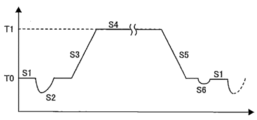
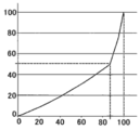
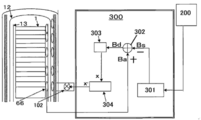
- FIG. 1 It is a partially cut front view which shows the substrate processing apparatus which concerns on one Embodiment of this invention. It is front sectional drawing of the substrate processing apparatus which concerns on one Embodiment of this invention. It is a figure which shows the flowchart which shows an example of the process regarding temperature among the film-forming processes which concern on embodiment of this invention. It is a figure which shows the temperature change in the furnace in the flowchart shown in FIG. It is a figure which shows the principal part of the substrate processing apparatus which concerns on one Embodiment of this invention. It is a figure which shows the hardware constitutions of the computer in the substrate processing apparatus which concerns on embodiment of this invention. It is a figure explaining the relationship between a control valve and cooling capacity in the cooling unit which concerns on embodiment of this invention.
- Example 1 of this invention it is the example of illustration which applied 3rd Embodiment to step S3. It is the figure which expanded A of FIG.
- Example 1 of this invention it is the example of illustration which applied 3rd Embodiment to step S5.
- Example 2 of this invention it is the example of illustration which applied 1st Embodiment and 2nd Embodiment to step S5.
- Example 1 of this invention it is the example of illustration which applied 3rd Embodiment to step S2.
- the substrate processing apparatus 10 is configured as a processing apparatus 10 that performs a film forming process in a method for manufacturing a semiconductor device.
- a substrate processing apparatus 10 shown in FIG. 1 includes a process tube 11 as a supported vertical reaction tube, and the process tube 11 includes an outer tube 12 and an inner tube 13 arranged concentrically with each other.
- the outer tube 12 is made of quartz (SiO 2) and is integrally formed in a cylindrical shape with the upper end closed and the lower end opened.
- the inner tube 13 is formed in a cylindrical shape with both upper and lower ends opened.
- a cylindrical hollow portion of the inner tube 13 forms a processing chamber 14 into which a boat to be described later is carried in, and a lower end opening of the inner tube 13 constitutes a furnace port 15 for taking in and out the boat.
- the boat 31 is configured to hold a plurality of wafers in a long aligned state. Therefore, the inner diameter of the inner tube 13 is set to be larger than the maximum outer diameter (for example, a diameter of 300 mm) of the wafer 1 to be handled.
- the lower end between the outer tube 12 and the inner tube 13 is hermetically sealed by a manifold 16 constructed in a substantially cylindrical shape.
- the manifold 16 is detachably attached to the outer tube 12 and the inner tube 13, respectively. Since the manifold 16 is supported by the housing 2 of the CVD apparatus, the process tube 11 is vertically installed.
- the outer tube 12 may be shown as the reaction tube 11 in the figure.
- the exhaust passage 17 is configured by a gap between the outer tube 12 and the inner tube 13 in a circular ring shape with a constant cross-sectional shape.
- one end of an exhaust pipe 18 is connected to the upper portion of the side wall of the manifold 16, and the exhaust pipe 18 communicates with the lowermost end portion of the exhaust path 17.
- An exhaust device 19 controlled by a pressure controller 21 is connected to the other end of the exhaust pipe 18, and a pressure sensor 20 is connected to the exhaust pipe 18.
- the pressure controller 21 is configured to feedback control the exhaust device 19 based on the measurement result from the pressure sensor 20.
- a gas introduction pipe 22 is disposed below the manifold 16 so as to communicate with the furnace port 15 of the inner tube 13.
- the gas introduction pipe 22 includes a raw material gas supply device and an inert gas supply device (hereinafter referred to as a gas supply device). 23) is connected.
- the gas supply device 23 is configured to be controlled by a gas flow rate controller 24.
- the gas introduced from the gas introduction pipe 22 into the furnace port 15 flows through the processing chamber 14 of the inner tube 13, passes through the exhaust passage 17, and is exhausted by the exhaust pipe 18.
- a seal cap 25 that closes the lower end opening is in contact with the manifold 16 from the lower side in the vertical direction.
- the seal cap 25 is constructed in a disk shape substantially equal to the outer diameter of the manifold 16, and is configured to be raised and lowered in the vertical direction by a boat elevator 26 installed in the standby chamber 3 of the housing 2.
- the boat elevator 26 is configured by a motor-driven feed screw shaft device and a bellows, and the motor 27 of the boat elevator 26 is configured to be controlled by a drive controller 28.
- a rotation shaft 30 is disposed on the center line of the seal cap 25 and is rotatably supported.
- the rotation shaft 30 is configured to be rotationally driven by a rotation mechanism 29 as a motor controlled by a drive controller 28. Yes.
- a boat 31 is vertically supported on the upper end of the rotating shaft 30.
- the boat 31 is provided with a pair of upper and lower end plates 32 and 33 and three holding members 34 vertically installed between the end plates 32 and 33, and a plurality of holding grooves 35 are longitudinally formed in the three holding members 34. Engraved at equal intervals in the direction. The holding grooves 35 carved in the same step in the three holding members 34 are configured to open facing each other. The boat 31 inserts the wafers 1 between the holding grooves 35 of the same stage of the three holding members 34 so that the plurality of wafers 1 are held in a state of being aligned horizontally and aligned with each other. It has become.
- a heat insulating cap portion 36 is disposed between the boat 31 and the rotating shaft 30.
- the rotary shaft 30 is configured so that the lower end of the boat 31 is separated from the position of the furnace port 15 by an appropriate distance by supporting the boat 31 in a state where it is lifted from the upper surface of the seal cap 25.
- the heat insulating cap part 36 insulates the vicinity of the furnace port 15.
- the heater unit 40 as a vertically installed heating device is concentrically arranged outside the reaction tube 11 and is installed in a state supported by the casing 2.
- the heater unit 40 includes a case 41.
- the case 41 is made of stainless steel (SUS) and is formed in a cylindrical shape, preferably a cylindrical shape with the upper end closed and the lower end opened.
- the inner diameter and the total length of the case 41 are set larger than the outer diameter and the total length of the outer tube 12.
- the plurality of control zones are divided into seven control zones U1, U2, CU, C, CL, L1, and L2 with the upper end side of the heater unit 40 extending toward the lower end side.
- a heat insulating structure 42 according to an embodiment of the present invention is installed in the case 41.
- the heat insulating structure 42 according to the present embodiment is formed in a cylindrical shape, preferably a cylindrical shape, and the side wall 43 of the cylindrical body is formed in a multi-layer structure. That is, the heat insulating structure 42 includes a side wall outer layer 45 disposed on the outer side of the side wall portion 43 and a side wall inner layer 44 disposed on the inner side of the side wall portion, and between the side wall outer layer 45 and the side wall inner layer 44,
- the partition part 105 which isolate
- a check damper 104 as a back diffusion prevention unit is provided in each zone.
- the cooling air 90 is configured to be supplied to the annular buffer 106 serving as a buffer section via the gas introduction path 107.
- the back diffusion preventing body 104a serves as a lid so that the atmosphere of the internal space 75 does not flow backward. You may comprise so that the pressure which this back diffusion prevention body 104a opens may be changed according to a zone.
- a heat insulating cloth 111 as a blanket is provided between the outer peripheral surface of the sidewall outer layer 45 and the inner peripheral surface of the case 41 so as to absorb the thermal expansion of the metal.
- the cooling air 90 supplied to the buffer unit 106 flows through the gas supply passage 108 provided in the side wall inner layer 44 (not shown in FIG. 2), and serves as a part of the supply path including the gas supply passage 108.
- the cooling air 90 is supplied to the internal space 75 from the opening hole 110.
- a ceiling wall portion 80 as a ceiling portion is covered on the upper end side of the side wall portion 43 of the heat insulating structure 42 so as to close the inner space 75.
- An exhaust hole 81 as a part of an exhaust path for exhausting the atmosphere of the inner space 75 is formed in the ceiling wall 80 in an annular shape, and a lower end that is an upstream end of the exhaust hole 81 communicates with the inner space 75. .
- the downstream end of the exhaust hole 81 is connected to the exhaust duct 82.
- the boat 31 holding the group of wafers is lifted by the boat elevator 26 by the seal cap 25 being lifted. It is carried into the processing chamber 14 of the inner tube 13 (boat loading).
- the seal cap 25 that has reached the upper limit is pressed against the manifold 16 to seal the inside of the reaction tube 11.
- the boat 31 is left in the processing chamber 14 while being supported by the seal cap 25.
- the temperature controller 64 performs sequence control so that the inside of the reaction tube 11 is heated to the target temperature by the side wall heating element 56.
- the error between the actual temperature rise inside the process tube 11 and the target temperature of the sequence control of the temperature controller 64 is corrected by feedback control based on the measurement result of the thermocouple 65. Further, the boat 31 is rotated by the motor 29.
- the raw material gas is introduced from the gas introduction tube 22 into the processing chamber 14 of the reaction tube 11 by the gas supply device 23.
- the raw material gas introduced by the gas introduction pipe 22 flows through the processing chamber 14 of the inner tube 13, passes through the exhaust passage 17, and is exhausted by the exhaust pipe 18.
- a predetermined film is formed on the wafer 1 by a thermal CVD reaction caused by contact of the source gas with the wafer 1 heated to a predetermined processing temperature.
- a purge gas such as nitrogen gas is introduced into the reaction tube 11 from the gas introduction tube 22.
- the cooling air 90 as the cooling gas is supplied from the intake pipe 101 to the gas introduction path 107 through the back diffusion prevention body 104.
- the supplied cooling air 90 is temporarily stored in an annular buffer 106 serving as an annular duct, and is blown out to the inner space 75 via a cooling gas passage 108 from a plurality of opening holes 110 serving as cooling gas supply ports.
- the cooling air 90 blown out from the opening hole 110 into the inner space 75 is exhausted by the exhaust hole 81 and the exhaust duct 82.
- the cooling air 90 can be used as the cooling gas.
- an inert gas such as nitrogen gas may be used as the cooling gas in order to further enhance the cooling effect or to prevent the heating element 56 from being corroded at high temperatures due to impurities in the air.
- the film processing for the wafer 1 is performed by the substrate processing apparatus 10.
- Reference numerals S1 to S6 shown in FIG. 4 indicate that steps S1 to S6 of FIG. 3 are performed.
- Step S1 (standby step) is a process of stabilizing the temperature in the furnace at a relatively low temperature T0.
- the substrate 18 has not yet been inserted into the furnace.
- Step S2 (boat loading step) is a process of inserting the substrate 1 held on the boat 31 into the furnace.
- the temperature of the boat 31 and the substrate 1 is lower than the temperature T0 in the furnace at this time, and as a result of inserting the substrate 1 held in the boat 31 into the furnace, an atmosphere outside the furnace (room temperature) is introduced into the furnace. Therefore, although the temperature in the furnace temporarily becomes lower than T0, the temperature in the furnace is stabilized again at the temperature T0 after some time by temperature control using the multi-cooling unit in this embodiment described later.
- Step S3 is a process of gradually increasing the temperature in the furnace from the temperature T0 to the target temperature T1 for performing a predetermined process on the substrate 1.
- Step S4 is a process of stabilizing the temperature in the furnace at the target temperature T1 in order to perform a predetermined process on the substrate 1.
- Step S5 is a process of gradually lowering the temperature in the furnace from the temperature T1 to the relatively low temperature T0 again after the process is completed.
- the temperature deviation between the zones can be reduced by lowering the temperature in the furnace from the temperature T1 to the temperature T0 by temperature control using a cooling unit in the present embodiment described later.
- Step S6 is a process of drawing the processed substrate 1 together with the boat 31 from the furnace.
- the atmosphere (room temperature) outside the furnace is introduced into the furnace, so that the temperature inside the furnace temporarily becomes lower than T0.
- the temperature in the furnace is stabilized again at the temperature T0 after a short time, and the process proceeds to step S1.
- the unprocessed substrate 1 is subsequently processed, it is better to stabilize the temperature in the furnace at the temperature T0 by temperature control using a cooling unit in the present embodiment described later.
- steps S1 to S6 After obtaining a stable state in which the furnace temperature is within a predetermined minute temperature range with respect to the target temperature and the state continues for a predetermined time, It is supposed to go to the step. Or recently, for the purpose of increasing the number of substrates 1 processed in a certain time, in steps S1, S2, S5, S6, etc., a stable state is not obtained and the process proceeds to the next step. ing.
- FIG. 5 is an illustrative example showing a multi-cooling unit in the present embodiment.
- the outer tube 12 and the inner tube 13 are collectively shown as the reaction tube 11, and the structure regarding the heating apparatus 40 is abbreviate
- the multi-cooling structure shown in FIG. 5 includes an intake pipe 101 that supplies cooling air 90 as a gas for cooling the inside of the furnace for each of a plurality of zones (U1, U2, CU, C, CL, L1, and L2), A control valve 102 as a conductance valve for adjusting the gas flow rate, a plurality of opening holes (quenching holes) 110 for ejecting gas toward the reaction tube, and an intake pipe 101 provided for each zone And an annular buffer 106 that temporarily stores the gas supplied from the intake pipe 101.
- Each opening hole 110 is configured to blow cooling air 90 stored in the annular buffer 106 to the inner space 75 via the cooling gas passage 108 provided in the side wall inner layer 44.
- the flow rate of the cooling air 90 introduced into the intake pipe 101 is set in accordance with the ratio of the zone length of each zone, and the control valve 102 is opened and closed, so that the gas jetted from the opening hole 110 toward the reaction pipe 11 It is configured to adjust the flow rate and flow velocity.
- the control valve 102 can change the flow rate and flow rate of the cooling air introduced into each zone by adjusting the opening of the valve by a temperature controller (not shown) according to the components in the reaction tube 101. it can.
- the intake pipe 101 is provided with a back diffusion prevention body (check damper) 104 that prevents back diffusion of the atmosphere from the processing chamber 14. Since the back diffusion preventing body 104 is exhausted from the exhaust port 81 above the inner space 75, it communicates with the lower side of the annular buffer 106 provided in each zone so that the cooling air 90 can be efficiently accumulated in the annular buffer 106. It is configured to be. When the quenching is not used, convection between the intake pipe 101 and the heat insulating structure 42 is prevented.
- a back diffusion prevention body (check damper) 104 that prevents back diffusion of the atmosphere from the processing chamber 14. Since the back diffusion preventing body 104 is exhausted from the exhaust port 81 above the inner space 75, it communicates with the lower side of the annular buffer 106 provided in each zone so that the cooling air 90 can be efficiently accumulated in the annular buffer 106. It is configured to be. When the quenching is not used, convection between the intake pipe 101 and the heat insulating structure 42 is prevented.
- the intake pipe 101 is configured to be provided with a throttle portion 103 as an orifice for suppressing the flow rate of the cooling air 90 ejected from the opening hole 110.
- the aperture 103 is provided for each zone as necessary.
- the flow path cross-sectional area of the intake pipe 101 provided for each zone and the flow path cross-sectional area of the annular buffer 106 are configured to be larger than the sum of the cross-sectional areas of the opening holes 110 provided for each zone. Further, each zone (for example, U2, CU, C, in FIG. 5) from approximately the same height as the uppermost area AR of the product wafer placed on the boat 31 to the lowermost area AR of the product wafer.
- the opening hole 110 is provided so that the flow rate and the flow velocity of the cooling air 90 blown to CL, L1) are uniform.
- the opening holes 110 are provided at the same interval in the circumferential direction and the vertical direction in the zone, and the cooling air 90 accumulated in the annular buffer 106 is passed through the cooling gas passage 108 provided in the inner wall layer 44 through the inner space. 75 to blow out.
- the heat insulating structure 42 used in the heating device 40 having a plurality of control zones (U1, U2, CU, C, CL, L1, L2 in this embodiment) has a side wall portion 43 formed in a cylindrical shape.
- the side wall 43 is formed in a multi-layer structure, and a partition 105 for separating the side wall 43 into a plurality of cooling zones (U1, U2, CU, C, CL, L1, L2) in the vertical direction;
- a cylindrical space between the side wall inner layer 44 and the side wall outer layer 45 which is composed of a space between the partition portions 105 adjacent in the vertical direction, and a plurality of layers of the side wall portions 43 for each cooling zone.
- the outer sidewall layer 45 Provided in the outer sidewall layer 45 disposed outside the gas inlet passage 107 communicating with the annular buffer 106 and the inner sidewall layer 44 disposed in the inner side of the plurality of layers of the sidewall portion 43 for each zone. Cooling in communication with buffer 106 The same interval in the circumferential direction and the vertical direction of the sidewall inner layer 44 so that the cooling air 90 is blown out from the cooling gas passage 108 to the space 75 for each cooling zone, and the space 75 provided inside the sidewall inner layer 44. It is the structure provided with the opening hole 110 provided by.
- the gas introduction path 107 is formed so as to communicate with the lower side of the annular buffer 106, and the opening hole 110 is provided so as to avoid a position facing the gas introduction path 107. Needless to say, the cooling air 90 blown out from the opening hole 110 is disposed so as to avoid the heating element 56 (not shown).
- the partition part 105 is arrange
- the number of control zones and the number of cooling zones are arbitrarily set.
- the structure in the process tube 11 facing the U1 zone and the L2 zone is that the U1 zone is a space (ceiling space portion) and is a heat insulation region including a heat insulation cap portion 36, and a region AR.
- the cooling of the reaction tube 11 facing the U1 zone and the L2 zone is not uniform.
- a dummy wafer used for temperature adjustment called a so-called side dummy wafer is placed on the boat 31. . Therefore, it is possible to reduce the influence on the temperature of the wafer 18 as a product in the case where the cooling of the reaction tube 11 is not uniform.
- a control computer 200 as a control unit includes a computer main body 203 including a CPU (Central Processing Unit) 201 and a memory 202, a communication IF (Interface) 204 as a communication unit, and a storage unit.
- the CPU 201 constitutes the center of the operation unit, executes a control program stored in the storage device 205, and executes a recipe (for example, a process recipe) recorded in the storage device 205 in accordance with an instruction from the operation unit 206. To do.
- a ROM Read Only Memory
- EEPROM Electrically Erasable Programmable Read Only Memory
- flash memory a hard disk, and the like
- a RAM Random Access Memory
- the communication unit 204 is electrically connected to the pressure controller 21, the gas flow rate controller 24, the drive controller 28, and the temperature controller 64 (these may be collectively referred to as a sub-controller), and exchanges data related to the operation of each component. Can do. Further, it is also electrically connected to a valve control unit 300 described later, and can exchange data for controlling the multi-cooling unit.
- control computer 200 has been described as an example.
- the present invention is not limited to this, and can be realized using a normal computer system.
- the above-described processing can also be executed by installing the program from a recording medium 207 such as a CDROM or USB storing a program for executing the above-described processing in a general-purpose computer.
- a communication IF 204 such as a communication line, a communication network, or a communication system may be used.
- the program may be posted on a bulletin board of a communication network and provided by being superimposed on a carrier wave via the network.
- the above-described processing can be executed by starting the program thus provided and executing it in the same manner as other application programs under the control of an OS (Operating System).
- OS Operating System
- the structure of the cooling unit according to the present embodiment has a configuration in which a control valve 102 is provided in the zone to reduce the difference between the devices caused by the fluctuation of the customer factory facility exhaust during the rapid cooling, the variation of the individual components, and the installation condition in the device. It has become. Furthermore, the cooling capacity can be adjusted by adjusting the flow rate supplied according to the opening degree of the control valve 102. For example, as shown in FIG. 7, the relationship between the opening degree of the control valve 102 and the cooling capacity is obtained in advance, and it is known that the cooling capacity is 87% when the opening degree is 50%.
- the horizontal axis in FIG. 7 is the cooling capacity (unit%), and the vertical axis is the opening degree (unit%) of the control valve 102.
- the opening degree is often set to 100% (cooling capacity 100%).
- the temperature is decreased along the rate set in the temperature decreasing step in step S5, or in step S3 in FIG.
- temperature control using the cooling unit in the present embodiment will be described. That is, temperature control and valve opening control in this embodiment will be described.
- the 1st control system using the cooling unit in this embodiment is called 1st Embodiment.
- a correlation diagram between the exhaust air volume introduced into each zone and the temperature drop rate is measured in advance, and the air volume of the introduced cooling air 90 is set according to the derived relational expression.
- the opening degree of the control valve 102 By fixing the opening degree of the control valve 102, a constant flow rate is supplied in advance for each zone, and a predetermined target temperature decrease rate can be obtained.
- the temperature drop rate can be obtained by an inexpensive and simple method, but it is greatly affected by the equipment configuration and equipment environment (for example, machine differences between equipment are likely to occur, or variations due to parts, factory exhaust equipment). The device reliability is low.
- the method of fixing the exhaust air volume of the cooling air 90 in the first embodiment actually measures the correlation between the exhaust air volume and the temperature drop rate, so it takes time and labor. There is a high possibility that start-up will be significantly delayed.
- control valve 102 Although only one control valve 102 is shown in FIG. 8 for the sake of explanation, similar control valves 102 are provided in other zones, and the opening degree differs in each zone. Can be. The introduced cooling gas is also supplied for each zone. Further, the control in the present embodiment is a control performed at the temperature lowering step S5 shown in FIG.
- the heater power is always 0% in the temperature lowering step S5, and therefore the description of the heater power calculation method is omitted.
- control for calculating the opening degree of the control valve 102 will be described.
- the control for calculating the opening degree of the control valve 102 in the present embodiment is different between the reference zone and other than the reference zone.
- a reference set value calculator 301 shown in FIG. 8A calculates a reference set value from the previous set value, current set value, and reference ramp rate set by the control unit 200.
- the subtractor 302 calculates a difference Bd by subtracting the reference set value Bs obtained by the above equation and the temperature Ba of the thermocouple 66 in the reference zone set in the reference zone, and a PD calculator 303 for calculating the control valve. To output.
- the control valve calculation PD calculator will be described with reference to FIG. 9A.
- the control valve PD calculator includes an adder 311, a proportional calculation 312, and a differentiation calculation 313.
- the proportional calculator 42 inputs the deviation I and outputs a value (P calculation) multiplied by a preset parameter Kp as a proportional value ⁇ .
- the proportional value ⁇ can be obtained according to the following equation.
- the differential calculator 43 inputs the deviation I, and outputs as a differential value R a value obtained by multiplying the result of the time differential calculation (D calculation) of the deviation I by a preset parameter Kd.
- the differential value R is obtained according to the following equation.
- the adder 51 inputs the proportional value ⁇ and the differential value R, calculates the sum of them, and outputs the manipulated variable M.
- the manipulated variable M of the control valve 102 is obtained from the above-described formulas (1) and (2). It is obtained according to the following formula.
- the previous set value, current set value, and reference ramp rate are input from the control unit 200 shown in FIG. 8A to the valve control unit 300, and the reference set value calculator 301 calculates the reference set value Bs.
- the thermocouple temperature in the reference zone Ba is input, and the subtracter 302 in the valve control 300 outputs a deviation Bd obtained by subtracting the reference set value Bs from the thermocouple temperature Ba of the reference zone.
- the control valve PD computing unit 303 uses the deviation Bd to generate PD.
- the operation amount X is determined by calculation.
- the manipulated variable X is converted to an opening X ′ by an opening converter 304, and the opening of the control valve 102 is changed.
- thermocouple temperature Ba of the reference zone is fed back to the valve control 300 again.
- the opening degree of the control valve 102 is changed every moment so that the deviation Bd between the thermocouple temperature Ba of the reference zone and the reference set value Bs becomes zero.
- the subtractor 302 calculates a difference Td as a result of subtracting the thermocouple temperature Ba of the reference zone from the temperature Ta other than the reference zone, and outputs the result to the control valve calculation PD calculator 303.
- the PD computing unit is as described above, and the content is the same, so the description is omitted.
- thermocouple temperature Ba of the reference zone is input, and in addition, the thermocouple temperature Ta other than the reference zone is input, and the subtractor 302 in the valve control unit 300 receives the temperature other than the reference zone.
- a deviation Td obtained by subtracting the thermocouple temperature Ba of the reference zone from Ta is output, and the PD calculation unit 303 for the control valve performs PD calculation using the deviation Td to determine the manipulated variable X.
- the manipulated variable X is converted to an opening X ′ by the opening converter 304, and the opening of the control valve 102 is changed.
- thermocouple 66 in the reference zone and the thermocouples 65 other than the reference zone are fed back to the valve controller 300 again.
- the opening degree of the control valve 102 is changed every moment so that the deviation Td between the thermocouple temperature other than the reference zone and the thermocouple temperature Ba of the reference zone becomes zero.
- the temperature other than the reference zone becomes zero with respect to the reference zone temperature. Therefore, it is possible to prevent the deviation between the zones from deteriorating.
- control in this embodiment is also performed for other zones, and is different for each zone.
- the opening can be set.
- the introduced cooling gas (cooling air) 90 is also supplied for each zone.
- the calculation for calculating the heater power is performed as usual. That is, the subtractor 21 calculates a result obtained by subtracting the set value S set by the host controller and the control amount A as the deviation D, and outputs it to the PID calculator 22.
- the PID calculator includes an adder 331, an integral calculation 332, a proportional calculation 333, and a differentiation calculation 334.
- the integral calculation 332 inputs the deviation I, and outputs a value obtained by multiplying the result of the deviation I by time integration calculation (I calculation) by a preset parameter Ki as an integral value N. Assuming that the deviation I at a specific time t is I (t) and the integral value N at that time is N (t), the integral value N is obtained according to the following equation.
- the proportional calculator 333 inputs the deviation I and outputs a value (P calculation) multiplied by a preset parameter Kp as a proportional value ⁇ .
- the proportional value ⁇ can be obtained according to the following equation.
- the differential calculator 334 inputs the deviation I, and outputs a value obtained by multiplying the result of the time differential calculation (D calculation) of the deviation I by a preset parameter Kd as the differential value R. Assuming that the deviation I at a specific time t is I (t) and the differential value R at that time is R (t), the differential value R is obtained according to the following equation.
- the adder 331 inputs the integral value N, the proportional value ⁇ , and the differential value R, calculates the sum of them, and outputs the manipulated variable M.
- the target value S is input from the control unit 200 to the temperature control unit 64 and, in addition, the control amount A from the cascade thermocouple 65 is input, and the subtractor 321 in the temperature control unit 64 A deviation D obtained by subtracting the control amount A from the target value S is output, and the PID calculator 322 performs PID calculation using the deviation D to determine the operation amount X.
- This manipulated variable X is converted into a target value W by a converter (not shown), the target value W and the control amount B from the heater thermocouple are input to the subtractor 323, and the subtractor 323 calculates the control amount B from the target value W.
- the subtracted deviation E is output, the PID calculator 324 performs PID calculation using the deviation E, and the manipulated variable Z is output as the output of the temperature control unit 64 and input to the heater unit 40.
- the control amounts A and B output from the heater unit 40 are returned to the temperature control unit 64 again. In this way, the operation amount Z output from the temperature control unit 64 is changed every moment so that the deviation D between the target value S and the control amount A becomes zero.
- PID control Such a control method is called PID control.
- the subtracter 302 calculates a result obtained by subtracting the POWER set value Zs set by the control unit 200 and the operation amount Z calculated by the temperature control unit 64 as a deviation Zd, and outputs the result to the control valve calculation PD calculator 303. It is.
- the power target value Zs is input from the control unit 200 to the valve control unit 300, and the heater power manipulated variable Z is input.
- the power target value is obtained in the subtracter 302 in the valve control unit 300.
- a deviation Zd obtained by subtracting the heater power manipulated variable Z from Zs is output, and the control valve PD computing unit 303 performs PD computation using the deviation Zd to determine the manipulated variable X.
- the manipulated variable X is converted to an opening X ′ by an opening converter 304, and the opening of the control valve 102 is changed.
- the heater power operation amount Z output from the heater unit 40 is returned to the valve control unit 300 again.
- the opening degree of the control valve 102 is changed every moment so that the deviation Zd between the heater power operation amount Z output from the temperature control unit 64 and the heater power target value Zs becomes zero.
- a conductance valve capable of adjusting the opening degree is installed for each zone as means for deviating the cooling capacity for each zone, and the cooling capacity is changed for each zone by varying the conductance valve according to the condition of the processing chamber. In this way, the temperature deviation between zones is improved.
- E It is possible to absorb and reduce machine-to-device differences caused by fluctuations in customer factory facility exhaust, variations in individual parts, and installation conditions in the device by controlling the conductance valve.
- F The heater power excess output resulting from the difference in temperature drop rate of each zone due to the structure in the reaction tube during rapid cooling by air cooling can be reduced by changing the cooling capacity by controlling the conductance valve, and an energy saving effect is expected it can.
- G During temperature recovery, temperature overshoot due to excess heat can be quickly eliminated by air cooling for each zone when the temperature is stable.
- H Improvement in temperature stability can be expected by shortening the temperature stabilization time during temperature recovery.
- the calculation which calculates heater power is implemented as usual.
- the subtractor 321 calculates a difference Dd by subtracting the deviation target value Ds set by the control unit 200 from the deviation D calculated by the temperature control unit 64 and outputs the result to the control valve calculation PD calculator 303. Is. Note that the explanation of the operation of the PD computing unit 303 has already been described above, and will be omitted.
- the deviation target value Ds is input from the control unit 200 to the valve control unit 300 and, in addition, the deviation D is input.
- the subtractor 302 in the valve control unit 300 calculates the deviation target value from the deviation D.
- the deviation Dd obtained by subtracting Ds is output, and the PD calculator 303 for the control valve performs PD calculation using the deviation Dd to determine the operation amount X.
- the manipulated variable X is converted to an opening X ′ by an opening converter 304, and the opening of the control valve 102 is changed.
- the deviation D calculated by the temperature control unit 64 is fed back to the valve control unit 300 again.
- the opening degree of the control valve 102 is changed every moment so that the deviation Dd between the deviation D sent out by the temperature control unit 64 and the deviation target value Ds becomes zero.
- the fourth embodiment performs substantially the same control as the third embodiment, the same effect as the third embodiment (at least one of the above-mentioned (d) to (h)) Play.
- the deviation D for example, overshoot
- the opening degree of the control valve 102 is not opened and cooled. Therefore, the opening degree of the control valve 102 is adjusted using the operation amount Z as a trigger. Example 3 is preferred.
- Example 1 The third embodiment is used for the temperature raising step S3, and the third embodiment is used for the temperature lowering step S5. Further, at least one of the temperature raising step S3 and the temperature lowering step S5 may be changed to the fourth embodiment.
- the temperature control unit 64 is configured to control the operation amount Z so that the thermocouple 65 becomes the target temperature T1 by the conventional PID control.
- the valve control unit 300 is configured to perform PD control so that the deviation Zd between the operation amount Z and the set operation amount Zs from the control unit 200 becomes zero. Thereby, the opening degree of the control valve 102 is adjusted, and the cooling capacity is controlled.
- the power value (operation amount Z) is controlled by the PID calculation including the I operation by the heater control by the conventional heater unit 40. The I operation is omitted in the unit control.
- the control valve 102 is configured to increase the opening degree so as to increase the cooling capacity and control the power output to be increased.
- the control valve 102 is configured to be controlled so that the opening degree of the control valve 102 is reduced to weaken the cooling capacity and the power output is reduced.
- cooling is performed by the cooling unit during the temperature increase even when the temperature increase rate is large.
- the power value operation amount Z
- the valve control 300 increases the opening of the control valve 102.
- the manipulated variable Z increases and the power value becomes equal to or higher than the target power value.
- the opening capacity of the valve 102 is reduced to reduce the cooling capacity.
- the power value (operation amount Z) decreases and the power value becomes equal to or less than the target power value. Since the cooling capacity is increased by increasing the opening degree of the control valve 102, it is possible to approach the target temperature T1 as compared with the conventional heater control. On the other hand, when the temperature is equal to or lower than the target temperature T1, the power value (operation amount Z) is increased, so that the valve control unit 300 reduces the opening of the control valve 102, so that it can be close to the target temperature T1. Such an operation is repeated to converge to the target temperature T1.
- Temperature recovery time is shortened by controlling the control valve 300 (assisted by a cooling unit). Moreover, compared with the case where only the temperature control of the heater unit 40 is performed so far, the temperature stabilization at the time of the transition from the heating step S3 to the film forming step S4 can be improved in each stage.
- the temperature is lowered to the target temperature T0 in the temperature lowering step S5.
- the temperature control unit 64 is configured to control the manipulated variable Z so that the thermocouple 65 becomes the target temperature T0 by the conventional PID control.
- the valve control unit 300 is configured to perform PD control so that the deviation Zd between the operation amount Z and the set operation amount Zs from the control unit 200 becomes zero. Thereby, the opening degree of the control valve 102 is adjusted, and the cooling capacity is controlled.
- the operation amount Z is set small in order to lower the temperature T1 to the temperature T0.
- the valve control unit 300 increases the opening degree of the control valve 102 to increase the cooling capacity.
- the manipulated variable Z is set large.
- the valve control unit 300 decreases the opening degree of the control valve 102 and weakens the cooling capacity. While repeating the heating by the heater unit 40 and the cooling by the valve control unit 300, it is possible to follow a preset temperature drop rate.
- the control of the valve control unit 300 (assist by the cooling unit) can be expected to significantly improve the temperature deviation between zones when the temperature is lowered and to save energy as compared with the conventional heater control alone.
- Example 2 The third embodiment is used for the temperature raising step S3, and the second embodiment is used for the temperature lowering step S5. Further, the temperature raising step S3 may be changed to the fourth embodiment, and the temperature lowering step S5 may be changed to the first embodiment. As described above, the combination of the first to fourth embodiments can be arbitrarily set.
- the temperature raising step S3 is the same as that of the first embodiment, the description thereof is omitted. Then, after predetermined processing is performed on the substrate 1 in step S4, the temperature is lowered to the temperature T1 target temperature T0 in the temperature lowering step S5. In the second embodiment, the power of the heater unit 40 in the temperature lowering step S5 is always 0%, and the temperature is rapidly decreased to improve the throughput (productivity improvement).
- the valve controller 200 is controlled based on a preset measured temperature Ba of a reference zone. Specifically, with respect to the reference zone, the previous set value T1, the current set value T0, and the reference ramp rate are input from the control unit 200 to the valve control unit 300, and the reference set value calculator 301 calculates the reference set value Bs.
- the subtractor 302 in the valve control 300 receives the thermocouple temperature Ba of the reference zone, and outputs a deviation Bd obtained by subtracting the reference set value Bs from the thermocouple temperature Ba of the reference zone.
- the control valve PD computing unit 303 is configured to perform PD computation using the deviation Bd and determine the manipulated variable X.
- the manipulated variable X is converted into an opening X ′, and the opening of the control valve 102 is adjusted.
- the subtracter 302 in the valve control unit 300 receives the thermocouple temperature Ba of the reference zone, and additionally inputs the thermocouple temperature Ta other than the reference zone.
- a deviation Td obtained by subtracting the thermocouple temperature Ba of the reference zone from Ta is output.
- the control valve PD computing unit 303 is configured to perform PD computation using the deviation Td and determine the manipulated variable X.
- the manipulated variable X is converted into an opening X ′, and the opening of the control valve 102 is adjusted.
- the temperature deviation indicates the difference between the maximum value and the minimum value of the temperatures measured in a plurality of control zones (maximum value ⁇ minimum value).
- FIG.12 and FIG.13 is an illustration example which applied the effect by the temperature control using the cooling unit in Embodiment 3 mentioned above to the temperature rising step (step S3), and the furnace in the temperature rising step (step S3) It is a figure when the inside temperature change is compared with a comparative example (without a cooling unit) and Embodiment 3 mentioned above.
- the temperature transition from the start of the temperature raising step (step S3) to the transition to the processing step (step S4) is illustrated by the temperature of the CU zone among the plurality of control zones.
- the horizontal axis shown in FIG. 12 is time (units), and the vertical axis is temperature (units C), and the start time of the temperature raising step (step S3) is shown as 0 minutes.
- the temperature deviation between zones from the temperature rising step (step S3) to the processing step (step S4) is indicated by a dotted line, from 500 ° C. (standby temperature T0) to 650 ° C. (target temperature T1). Until now, the temperature change in the furnace when the temperature is raised at a rate of 10 ° C./min is shown by a solid line.
- FIG. 13 is an enlarged view of a portion (A in FIG. 12) that shifts from the heating step (step S3) to the processing step (step S4).
- FIG. 13 shows the temperature change in the furnace after 15 minutes from the start of the temperature raising step (step S3), but this time of 15 minutes depends on the heating by the heating device 40 and the cooling unit 100. This is the time when temperature control is performed using both cooling.
- the overshoot in the comparative example is 2 ° C., and the time during which the upper and lower limit values are stabilized within 1 ° C. is approximately 21 minutes from the start of the temperature raising step (step S3).
- the overshoot in the temperature control (Embodiment 3) using the cooling unit 100 in the embodiment is 0.5 ° C., and the time until the temperature stabilizes within 1 ° C. is about 17 minutes.
- the temperature stability is remarkably improved as compared with the comparative example.
- 17 minutes is the time when the temperature in the furnace (the temperature of the CU zone) has reached 649 ° C. (target temperature—lower limit) when the temperature is raised from 500 ° C. to 650 ° C. After reaching °C, it converges to the range of upper and lower limits (1 °C).
- the temperature controllability is significantly improved as compared with the comparative example when the temperature is raised in advance.
- the temperature control according to the third embodiment is completed before the temperature in the furnace (the temperature of the CU zone) reaches the upper and lower limit range within the range of the temperature rise. Overheating is suppressed. On the other hand, in the comparative example, overshoot occurs, and it takes time for the temperature of the CU zone to converge within the range of the upper and lower limit values.
- both the heating by the heating device 40 and the cooling by the cooling unit 100 are used to follow a predetermined rate (in this case, 10 ° C./min). Therefore, the time for convergence to the upper and lower limit values can be shortened compared to the comparative example (without the cooling unit). Furthermore, according to the third embodiment, the temperature can be kept within the upper and lower limit values even if overshooting occurs. Therefore, it is possible to shift to the next processing step (step S4) earlier than the comparative example, and the throughput can be improved.
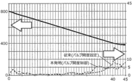
- FIG. 14 is an illustrative example in which the temperature control using the cooling unit 100 in the above-described third embodiment is applied to the temperature lowering step (step S5), and the temperature change in the furnace at the temperature lowering step (step S5) is a comparative example ( It is a figure when it compares with valve
- FIG. 14 shows the temperature transition from the temperature lowering step (step S5) to the next step (step S6) before the transition to the next step (step S6) as the average temperature of the furnace temperature measured by thermocouples in all zones.
- the horizontal axis shown in FIG. 14 is time (unit), and the vertical axis is temperature (unit ° C).
- the left vertical axis is the temperature in the furnace, and the right vertical axis is the temperature deviation.
- comparison should be made without a cooling unit. However, in the case of no cooling (only power off of the heating device 40), the temperature cannot be lowered at a rate of 10 ° C / min.
- Embodiment 3 controlling the opening of the valve).
- FIG. 14 shows the temperature deviation between zones from the temperature lowering step (step S5) to the next step (step S6) by a dotted line, and the temperature change of the average temperature in all zones is shown by a solid line. It is a thing. As shown in FIG. 14, the temperature change in the furnace is shown when the temperature is lowered from 800 ° C. to 400 ° C. at a rate of 10 ° C./min. This temperature change is shown by the average temperature of the furnace temperature measured with the thermocouple of all the zones. And the temperature change in this furnace and the temperature deviation between zones are substantially equal in a comparative example and Embodiment 3. FIG.
- the heater power is applied and heated by the heating device 40 so that the temperature drop is delayed to a rate of 10 ° C./min.
- both cooling and heating by the heating device 40 are adjusted by the cooling air 90. Therefore, energy saving can be realized as compared with the comparative example in which the temperature drop rate (10 ° C./min) is controlled only by the heater power.
- FIG. 15 is an illustrative example in which the temperature control using the cooling unit 100 in the first and second embodiments described above is applied to the temperature lowering step (step S5), and the temperature change in the furnace in the temperature lowering step (step S5).
- FIG. 2 is a diagram when a comparison is made between a comparative example (valve 100% open and fixed), Embodiment 1 (valve opening is fixed for each cooling zone), and Embodiment 2 (with valve opening control).
- FIG. 15 also shows the average temperature in the furnace measured by thermocouples in all zones, with respect to the temperature transition (solid line) from the temperature lowering step (step S5) to the next step (step S6). Shown in temperature.
- the horizontal axis shown in FIG. 15 is time (units), and the vertical axis is temperature (unit ° C).
- the left vertical axis is the temperature in the furnace, and the right vertical axis is the temperature deviation.
- a temperature change in the furnace is shown when the heating device 40 is cooled down from 800 ° C. with the power off (heater power 0%).
- the time to reach from 800 ° C. to 400 ° C. is naturally about 12 minutes first in the comparative example (the valve opening is fixed at 100%) in order of increasing supply of cooling gas.
- Embodiment 1 fixed for each valve opening zone
- Embodiment 2 with valve opening control
- the temperature deviation (dotted line) between zones when the heating device 40 is cooled down from 800 ° C. with the power off (heater power 0%) is shown.
- the temperature deviation between the zones of the comparative example exceeds the maximum of 60 ° C.
- the temperature deviation between the zones is 20 ° C. or more from 3 minutes after the start of temperature decrease from 800 ° C.
- the temperature deviation between the zones is about 20 ° C. from 10 minutes after the start of temperature decrease from 800 ° C.
- the temperature deviation between the zones is reduced compared to the comparative example (valve opening 100% fixed), it seems that there is a limit to the control for fixing the valve opening of the cooling air 90.
- the temperature deviation between zones in Embodiment 2 is the temperature deviation between zones without the maximum value of temperature deviation between zones exceeding 10 ° C. during the temperature lowering step (step S5). Is about 8 ° C.
- the temperature control using the cooling unit 100 according to the second embodiment (or the first embodiment) is performed, thereby improving the throughput over the third embodiment. Can be planned.
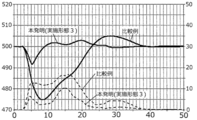
- FIG. 16 is a view showing the effect of temperature control using the cooling unit 100 in the above-described third embodiment in a boat loading step (step S2), and the temperature change in the furnace in step S2 is a comparative example (no cooling unit). ) And the third embodiment described above. As shown in FIG. 16, it is possible to shorten the temperature recovery time when the temperature drop due to the disturbance as in step S2 cannot be avoided.
- step S2 the temperature transition of step S2 is illustrated by the temperature of the L1 zone among the plurality of control zones.
- the horizontal axis shown in FIG. 16 is time (units), and the vertical axis is temperature (unit ° C.).
- the left vertical axis is the temperature in the furnace, and the right vertical axis is the temperature deviation.
- the temperature change in the furnace (solid line) and the temperature deviation between the zones (dotted line) when the boat 31 is charged into the furnace while maintaining at 500 ° C. are shown.
- the temperature drop is a maximum value of 25 ° C. and the maximum temperature deviation is about 20 ° C.
- the temperature control using the cooling unit in Embodiment 3 described above was used to control the cooling unit in Embodiment 3 described above.
- the maximum temperature drop was smaller than 10 ° C., and the maximum temperature deviation was about 10 ° C.
- the time when the temperature was stabilized again at 500 ° C. ( ⁇ 2 ° C.) was 35 minutes in the comparative example, and 21 minutes in the third embodiment.
- the temperature recovery time when the temperature decrease due to the disturbance as in step S2 cannot be avoided can be shortened. Therefore, according to the third embodiment, it is possible to shift to the next heating step (step S3) earlier than the comparative example, and it is possible to improve the throughput.
- step S2 when the boat loading step (step S2) is performed at a relatively low temperature (500 ° C. in FIG. 16), in the comparative example, the power is excessively output with respect to the temperature fluctuation due to the disturbance of the boat loading.
- the temperature becomes equal to or higher than the set value, and the power is turned off (heater power 0%) so as to reduce the power. It took a long time for the furnace temperature to fall to the set value in this power off state (heater power 0%), and the temperature recovery time was long.
- the cooling is strengthened (valve OPEN) when the output is less than or equal to the preset power value, and the cooling is weakened (valve close) when the output is equal to or greater than the preset power value.
- the purpose is to output a certain power.
- the power off (heater power 0%) state is shortened as in the comparative example, the power value can be increased or decreased with respect to temperature fluctuations due to disturbance, temperature controllability is improved, and temperature recovery time is shortened. can do.
- the temperature control using the cooling unit in the third embodiment described above can shorten the temperature recovery time in step S6 (boat unloading step) as compared with the comparative example.
- the present invention can be applied not only to a semiconductor manufacturing apparatus but also to an apparatus for processing a glass substrate such as an LCD apparatus.
- a glass substrate such as an LCD apparatus.
- it is used for oxidation treatment and diffusion treatment on semiconductor wafers on which semiconductor integrated circuit devices (semiconductor devices) are made, reflow for annealing and planarization of carriers after ion implantation, and film formation treatment by annealing and thermal CVD reaction.
- the present invention can be applied to an effective substrate using a substrate processing apparatus.
- the present invention can be applied to any processing apparatus that performs processing in a state in which a substrate to be processed is accommodated in a processing chamber and heated by a heating apparatus.
Landscapes
- Chemical & Material Sciences (AREA)
- Engineering & Computer Science (AREA)
- General Chemical & Material Sciences (AREA)
- Chemical Kinetics & Catalysis (AREA)
- Materials Engineering (AREA)
- Mechanical Engineering (AREA)
- Metallurgy (AREA)
- Organic Chemistry (AREA)
- Chemical Vapour Deposition (AREA)
- Automation & Control Theory (AREA)
Abstract
Description







Claims (12)
- ボートに載置された状態の基板を加熱するヒータユニットと、所定の温度に維持するよう前記ヒータユニットを制御する温度制御部と、反応管に向けて供給するガスの流量を調整する制御バルブの開度を調整するバルブ制御部と、所定の昇温レートで前記所定の温度まで昇温させる昇温ステップ、前記所定の温度で前記基板を処理する処理ステップ、前記所定の温度から所定の降温レートで降温させる降温ステップを含むレシピを実行指示する制御部と、を備え、前記制御部は、前記ヒータユニットによる加熱及び前記制御バルブから供給されるガスによる冷却を並行させて、前記所定の昇温レート及び前記所定の降温レートに追従させるように、前記温度制御部及び前記バルブ制御部を制御するよう構成されている基板処理装置。
- 更に、複数の冷却ゾーンに分割され、前記冷却ゾーン毎に前記制御バルブを設けるクーリングユニットを有し、前記制御バルブは、前記冷却ゾーン毎に個別に開度が調整されるよう構成されている請求項1記載の基板処理装置。
- 前記制御ゾーンの数と前記冷却ゾーンの数が一致するように構成されている請求項2に記載の基板処理装置。
- 前記制御部は、前記ヒータユニットによる加熱及び前記制御バルブから供給されるガスによる冷却を並行させて、前記昇温ステップから前記処理ステップへの移行時において発生するオーバシュートの時間を短縮させるように、前記温度制御部及び前記バルブ制御部を制御するよう構成されている請求項1記載の基板処理装置。
- 前記制御部は、前記制御バルブから供給されるガスによる冷却により、前記降温ステップの時間を短縮させるように、前記バルブ制御部を制御するよう構成されている請求項1記載の基板処理装置。
- 前記制御ゾーン毎に設けられた熱電対を有し、前記制御部は、基準ゾーンに選択された基準ゾーンの温度を検出する熱電対と、基準ゾーン以外に設けられた熱電対との温度偏差がゼロになるように前記温度制御部及び前記制御バルブを制御するよう構成されている請求項1記載の基板処理装置。
- 前記温度制御部は、前記基準ゾーンの温度を検出する熱電対と前記制御部からの設定値から算出された基準設定値との偏差がゼロになるように前記制御バルブを制御するように構成されている請求項6記載の基板処理装置。
- 前記制御部は、前記ヒータユニットによる加熱及び前記制御バルブから供給されるガスによる冷却を並行させて、前記昇温ステップから前記処理ステップへの移行時において発生するオーバシュートの時間を短縮させるように、前記温度制御部及び前記バルブ制御部に制御するよう構成されている請求項1記載の基板処理装置。
- 前記制御部は、前記昇温ステップにおいて、前記所定の温度に到達する前に前記制御バルブから供給されるガスを停止させるように前記バルブ制御部を制御するよう構成されている請求項1に記載の基板処理装置。
- 更に、前記レシピは、複数枚の基板をボートに保持させて、前記反応管内に装入するボートロードステップを有し、前記制御部は、前記ヒータユニットによる加熱及び前記制御バルブから供給されるガスによる冷却を並行させて、前記ボートロードステップにおいて発生するオーバシュートの時間を短縮させるように、前記温度制御部及び前記バルブ制御部に制御するよう構成されている請求項1記載の基板処理装置。
- 複数枚の基板をボートに保持させて、反応管内に装入する工程と、前記反応管内の温度を所定の昇温レートで所定の温度にする昇温工程と、ヒータユニットにより前記所定の温度に制御しつつ、前記基板を処理する工程と、前記反応管内の温度を所定の降温レートで前記所定の温度よりも低い温度にする降温工程と、を有する半導体装置の製造方法であって、前記昇温工程において、前記ヒータユニットによる加熱及び制御バルブから供給されるガスによる冷却を並行させて前記所定の昇温レートに追従させ、前記降温工程において、前記ヒータユニットによる加熱及び制御バルブから供給されるガスによる冷却を並行させて前記所定の降温レートに追従させる半導体装置の製造方法。
- 反応管内の温度を所定の温度に維持するよう、前記反応管内に装入されたボートに載置された基板を加熱するヒータユニットを制御する温度制御部と、前記反応管に向けて供給されるガスの流量を調整する制御バルブの開度を調整するバルブ制御部と、を備えた基板処理装置に、複数枚の基板をボートに保持させる手順と、前記ボートを反応管に装入する手順と、前記反応管内の温度を所定の昇温レートで所定の温度に昇温する手順と、前記所定の温度に制御しつつ、前記基板を処理する手順と、前記反応管内の温度を所定の降温レートで前記所定の温度よりも低い温度に降温する手順と、を実行させるプログラムであって、前記昇温する手順において、前記ヒータユニットによる加熱及び前記制御バルブから供給されるガスによる冷却を並行させて前記所定の昇温レートに追従させ、前記降温する手順において、前記ヒータユニットによる加熱及び前記制御バルブから供給されるガスによる冷却を並行させて前記所定の降温レートに追従させるプログラム。
Priority Applications (4)
| Application Number | Priority Date | Filing Date | Title |
|---|---|---|---|
| JP2018553667A JP6789314B2 (ja) | 2016-11-30 | 2017-09-07 | 基板処理装置、半導体装置の製造方法及びプログラム |
| KR1020197015248A KR102287466B1 (ko) | 2016-11-30 | 2017-09-07 | 기판 처리 장치, 반도체 장치의 제조 방법 및 프로그램 |
| US16/425,652 US11761087B2 (en) | 2016-11-30 | 2019-05-29 | Substrate processing apparatus and non-transitory computer-readable recording medium |
| US18/449,750 US12503770B2 (en) | 2016-11-30 | 2023-08-15 | Substrate processing apparatus and non-transitory computer-readable recording medium |
Applications Claiming Priority (2)
| Application Number | Priority Date | Filing Date | Title |
|---|---|---|---|
| JP2016-232813 | 2016-11-30 | ||
| JP2016232813 | 2016-11-30 |
Related Child Applications (1)
| Application Number | Title | Priority Date | Filing Date |
|---|---|---|---|
| US16/425,652 Continuation US11761087B2 (en) | 2016-11-30 | 2019-05-29 | Substrate processing apparatus and non-transitory computer-readable recording medium |
Publications (1)
| Publication Number | Publication Date |
|---|---|
| WO2018100826A1 true WO2018100826A1 (ja) | 2018-06-07 |
Family
ID=62241381
Family Applications (1)
| Application Number | Title | Priority Date | Filing Date |
|---|---|---|---|
| PCT/JP2017/032242 Ceased WO2018100826A1 (ja) | 2016-11-30 | 2017-09-07 | 基板処理装置、半導体装置の製造方法及びプログラム |
Country Status (4)
| Country | Link |
|---|---|
| US (2) | US11761087B2 (ja) |
| JP (1) | JP6789314B2 (ja) |
| KR (1) | KR102287466B1 (ja) |
| WO (1) | WO2018100826A1 (ja) |
Cited By (7)
| Publication number | Priority date | Publication date | Assignee | Title |
|---|---|---|---|---|
| CN112095089A (zh) * | 2019-06-17 | 2020-12-18 | 爱思开海力士有限公司 | 处理衬底的装置和方法 |
| WO2022070310A1 (ja) * | 2020-09-30 | 2022-04-07 | 株式会社Kokusai Electric | 基板処理装置、温度制御プログラム、半導体装置の製造方法及び温度制御方法 |
| JP2024003678A (ja) * | 2022-06-27 | 2024-01-15 | 東京エレクトロン株式会社 | 熱処理装置、および熱処理装置の温度調整方法 |
| WO2024142528A1 (ja) | 2022-12-26 | 2024-07-04 | 株式会社Kokusai Electric | 温度制御方法、半導体装置の製造方法、および基板処理装置並びにプログラム |
| US12085338B2 (en) | 2019-06-12 | 2024-09-10 | Kokusai Electric Corporation | Heater, temperature control system, and processing apparatus |
| US12392554B2 (en) | 2019-06-17 | 2025-08-19 | SK Hynix Inc. | Apparatus for processing a substrate and method of operating the same |
| US12566423B2 (en) | 2020-09-28 | 2026-03-03 | Kokusai Electric Corporation | Temperature control method, method of manufacturing semiconductor device, non-transitory computer-readable recording medium and substrate processing apparatus |
Families Citing this family (11)
| Publication number | Priority date | Publication date | Assignee | Title |
|---|---|---|---|---|
| US11043402B2 (en) * | 2017-09-12 | 2021-06-22 | Kokusai Electric Corporation | Cooling unit, heat insulating structure, and substrate processing apparatus |
| JP6843087B2 (ja) * | 2018-03-12 | 2021-03-17 | 株式会社Kokusai Electric | 半導体装置の製造方法、基板処理装置およびプログラム |
| US10903096B2 (en) * | 2018-04-06 | 2021-01-26 | Varian Semiconductor Equipment Associates, Inc. | System and apparatus for process chamber window cooling |
| KR102866804B1 (ko) * | 2020-04-24 | 2025-09-30 | 에이에스엠 아이피 홀딩 비.브이. | 냉각 가스 공급부를 포함한 수직형 배치 퍼니스 어셈블리 |
| CN111610714A (zh) * | 2020-05-20 | 2020-09-01 | 杭州舒尔姿氨纶有限公司 | 一种dcs对电加热器的线性控制方法 |
| KR102860972B1 (ko) * | 2020-06-10 | 2025-09-16 | 삼성전자주식회사 | 반도체 증착 모니터링 장치 |
| JP7772358B2 (ja) * | 2021-09-02 | 2025-11-18 | 株式会社クリーンプラネット | 発熱装置および発熱素子の冷却方法 |
| KR102947483B1 (ko) * | 2022-08-29 | 2026-04-01 | 삼성전자주식회사 | 기판 처리 설비 및 이를 이용한 반도체 장치 제조 방법 |
| CN116007390A (zh) * | 2022-12-15 | 2023-04-25 | 湖南优热科技有限责任公司 | 一种带有快速主动冷却系统的石墨化炉 |
| JP2024132068A (ja) * | 2023-03-17 | 2024-09-30 | 株式会社Kokusai Electric | 基板冷却方法、半導体装置の製造方法、基板冷却システム、基板処理装置およびプログラム |
| CN117542767B (zh) * | 2024-01-10 | 2024-03-26 | 合肥费舍罗热工装备有限公司 | 一种半导体立式熔接炉 |
Citations (6)
| Publication number | Priority date | Publication date | Assignee | Title |
|---|---|---|---|---|
| JPH09190982A (ja) * | 1996-01-11 | 1997-07-22 | Toshiba Corp | 半導体製造装置 |
| JP2002075890A (ja) * | 2000-08-23 | 2002-03-15 | Tokyo Electron Ltd | 熱処理装置の降温レート制御方法および熱処理装置 |
| JP2003031510A (ja) * | 2001-07-19 | 2003-01-31 | Sharp Corp | 熱処理装置および熱処理方法 |
| JP2006222327A (ja) * | 2005-02-14 | 2006-08-24 | Hitachi Kokusai Electric Inc | 基板処理装置 |
| JP2011216854A (ja) * | 2010-03-15 | 2011-10-27 | Hitachi Kokusai Electric Inc | 熱処理装置及び基板処理方法 |
| JP2014209569A (ja) * | 2013-03-25 | 2014-11-06 | 株式会社日立国際電気 | 断熱構造体及び半導体装置の製造方法 |
Family Cites Families (5)
| Publication number | Priority date | Publication date | Assignee | Title |
|---|---|---|---|---|
| TW266230B (ja) * | 1993-09-09 | 1995-12-21 | Tokyo Electron Co Ltd | |
| JP5028957B2 (ja) * | 2005-12-28 | 2012-09-19 | 東京エレクトロン株式会社 | 成膜方法及び成膜装置並びに記憶媒体 |
| KR20080099449A (ko) | 2007-05-09 | 2008-11-13 | 삼성에스디아이 주식회사 | 이차 전지 |
| JP2012181337A (ja) * | 2011-03-01 | 2012-09-20 | Ricoh Co Ltd | 光沢付与装置及びこれを用いた画像形成装置 |
| JPWO2015115002A1 (ja) | 2014-01-29 | 2017-03-23 | 株式会社日立国際電気 | 微細パターンの形成方法、半導体装置の製造方法、基板処理装置及び記録媒体 |
-
2017
- 2017-09-07 WO PCT/JP2017/032242 patent/WO2018100826A1/ja not_active Ceased
- 2017-09-07 KR KR1020197015248A patent/KR102287466B1/ko active Active
- 2017-09-07 JP JP2018553667A patent/JP6789314B2/ja active Active
-
2019
- 2019-05-29 US US16/425,652 patent/US11761087B2/en active Active
-
2023
- 2023-08-15 US US18/449,750 patent/US12503770B2/en active Active
Patent Citations (6)
| Publication number | Priority date | Publication date | Assignee | Title |
|---|---|---|---|---|
| JPH09190982A (ja) * | 1996-01-11 | 1997-07-22 | Toshiba Corp | 半導体製造装置 |
| JP2002075890A (ja) * | 2000-08-23 | 2002-03-15 | Tokyo Electron Ltd | 熱処理装置の降温レート制御方法および熱処理装置 |
| JP2003031510A (ja) * | 2001-07-19 | 2003-01-31 | Sharp Corp | 熱処理装置および熱処理方法 |
| JP2006222327A (ja) * | 2005-02-14 | 2006-08-24 | Hitachi Kokusai Electric Inc | 基板処理装置 |
| JP2011216854A (ja) * | 2010-03-15 | 2011-10-27 | Hitachi Kokusai Electric Inc | 熱処理装置及び基板処理方法 |
| JP2014209569A (ja) * | 2013-03-25 | 2014-11-06 | 株式会社日立国際電気 | 断熱構造体及び半導体装置の製造方法 |
Cited By (12)
| Publication number | Priority date | Publication date | Assignee | Title |
|---|---|---|---|---|
| US12085338B2 (en) | 2019-06-12 | 2024-09-10 | Kokusai Electric Corporation | Heater, temperature control system, and processing apparatus |
| CN112095089A (zh) * | 2019-06-17 | 2020-12-18 | 爱思开海力士有限公司 | 处理衬底的装置和方法 |
| US12392554B2 (en) | 2019-06-17 | 2025-08-19 | SK Hynix Inc. | Apparatus for processing a substrate and method of operating the same |
| US12566423B2 (en) | 2020-09-28 | 2026-03-03 | Kokusai Electric Corporation | Temperature control method, method of manufacturing semiconductor device, non-transitory computer-readable recording medium and substrate processing apparatus |
| WO2022070310A1 (ja) * | 2020-09-30 | 2022-04-07 | 株式会社Kokusai Electric | 基板処理装置、温度制御プログラム、半導体装置の製造方法及び温度制御方法 |
| JPWO2022070310A1 (ja) * | 2020-09-30 | 2022-04-07 | ||
| KR20230053689A (ko) | 2020-09-30 | 2023-04-21 | 가부시키가이샤 코쿠사이 엘렉트릭 | 기판 처리 장치, 온도 제어 프로그램, 반도체 장치의 제조 방법 및 온도 제어 방법 |
| CN116157902A (zh) * | 2020-09-30 | 2023-05-23 | 株式会社国际电气 | 基板处理装置、温度控制程序、半导体器件的制造方法以及温度控制方法 |
| JP7362940B2 (ja) | 2020-09-30 | 2023-10-17 | 株式会社Kokusai Electric | 基板処理装置、温度制御プログラム、半導体装置の製造方法及び温度制御方法 |
| JP2024003678A (ja) * | 2022-06-27 | 2024-01-15 | 東京エレクトロン株式会社 | 熱処理装置、および熱処理装置の温度調整方法 |
| WO2024142528A1 (ja) | 2022-12-26 | 2024-07-04 | 株式会社Kokusai Electric | 温度制御方法、半導体装置の製造方法、および基板処理装置並びにプログラム |
| EP4645373A1 (en) | 2022-12-26 | 2025-11-05 | Kokusai Electric Corporation | Temperature control method, semiconductor device manufacturing method, substrate treatment device, and program |
Also Published As
| Publication number | Publication date |
|---|---|
| KR20190067250A (ko) | 2019-06-14 |
| JP6789314B2 (ja) | 2020-11-25 |
| US11761087B2 (en) | 2023-09-19 |
| US20190276938A1 (en) | 2019-09-12 |
| KR102287466B1 (ko) | 2021-08-06 |
| US12503770B2 (en) | 2025-12-23 |
| JPWO2018100826A1 (ja) | 2019-10-17 |
| US20230383411A1 (en) | 2023-11-30 |
Similar Documents
| Publication | Publication Date | Title |
|---|---|---|
| WO2018100826A1 (ja) | 基板処理装置、半導体装置の製造方法及びプログラム | |
| JP6170847B2 (ja) | 断熱構造体、加熱装置、基板処理装置および半導体装置の製造方法 | |
| JP6752291B2 (ja) | 基板処理装置、クーリングユニット及び断熱構造体並びに半導体装置の製造方法 | |
| CN109494172B (zh) | 冷却单元、绝热结构体、基板处理装置、以及半导体装置的制造方法 | |
| JP5751549B2 (ja) | 熱処理装置及び半導体の製造方法 | |
| US11043402B2 (en) | Cooling unit, heat insulating structure, and substrate processing apparatus | |
| JP5647712B2 (ja) | 基板処理方法、半導体装置の製造方法および半導体製造装置 | |
| JP7362940B2 (ja) | 基板処理装置、温度制御プログラム、半導体装置の製造方法及び温度制御方法 | |
| US20240393050A1 (en) | Heater, temperature control system, and processing apparatus | |
| JP7101718B2 (ja) | 加熱部、温度制御システム、処理装置および半導体装置の製造方法 | |
| CN100367458C (zh) | 热处理装置和热处理方法 | |
| JP7289355B2 (ja) | 基板処理装置、半導体装置の製造方法及びプログラム | |
| JP4610908B2 (ja) | 基板処理装置及び半導体装置の製造方法 | |
| JP4463633B2 (ja) | 基板処理装置及び基板の製造方法 | |
| US20250112063A1 (en) | Substrate processing method, method of manufacturing semiconductor device, recording medium, and substrate processing apparatus | |
| JP2005136370A (ja) | 基板処理装置 | |
| WO2025158707A1 (ja) | 温度制御システム、温度制御方法、半導体装置の製造方法及び基板処理装置 |
Legal Events
| Date | Code | Title | Description |
|---|---|---|---|
| 121 | Ep: the epo has been informed by wipo that ep was designated in this application |
Ref document number: 17875432 Country of ref document: EP Kind code of ref document: A1 |
|
| ENP | Entry into the national phase |
Ref document number: 2018553667 Country of ref document: JP Kind code of ref document: A |
|
| ENP | Entry into the national phase |
Ref document number: 20197015248 Country of ref document: KR Kind code of ref document: A |
|
| NENP | Non-entry into the national phase |
Ref country code: DE |
|
| 122 | Ep: pct application non-entry in european phase |
Ref document number: 17875432 Country of ref document: EP Kind code of ref document: A1 |