WO2018097238A1 - 光変調素子および情報記録媒体 - Google Patents
光変調素子および情報記録媒体 Download PDFInfo
- Publication number
- WO2018097238A1 WO2018097238A1 PCT/JP2017/042183 JP2017042183W WO2018097238A1 WO 2018097238 A1 WO2018097238 A1 WO 2018097238A1 JP 2017042183 W JP2017042183 W JP 2017042183W WO 2018097238 A1 WO2018097238 A1 WO 2018097238A1
- Authority
- WO
- WIPO (PCT)
- Prior art keywords
- light
- image
- optical member
- reproduction
- specific wavelength
- Prior art date
Links
- 230000003287 optical effect Effects 0.000 claims abstract description 97
- 230000005540 biological transmission Effects 0.000 claims abstract description 22
- 239000000463 material Substances 0.000 claims description 56
- 238000000034 method Methods 0.000 claims description 36
- 239000000758 substrate Substances 0.000 claims description 34
- 238000002834 transmittance Methods 0.000 claims description 30
- 238000005286 illumination Methods 0.000 claims description 15
- 239000003086 colorant Substances 0.000 claims description 12
- 238000010521 absorption reaction Methods 0.000 claims description 10
- 230000003595 spectral effect Effects 0.000 claims description 10
- 239000010410 layer Substances 0.000 description 142
- 229920005989 resin Polymers 0.000 description 43
- 239000011347 resin Substances 0.000 description 43
- 238000010586 diagram Methods 0.000 description 20
- 230000001427 coherent effect Effects 0.000 description 19
- 238000004519 manufacturing process Methods 0.000 description 12
- 239000000975 dye Substances 0.000 description 11
- 230000031700 light absorption Effects 0.000 description 9
- 230000008929 regeneration Effects 0.000 description 8
- 238000011069 regeneration method Methods 0.000 description 8
- 230000001678 irradiating effect Effects 0.000 description 7
- 239000000853 adhesive Substances 0.000 description 4
- 230000001070 adhesive effect Effects 0.000 description 4
- 239000006185 dispersion Substances 0.000 description 4
- 239000012071 phase Substances 0.000 description 4
- 238000007639 printing Methods 0.000 description 4
- 238000009826 distribution Methods 0.000 description 3
- 239000004417 polycarbonate Substances 0.000 description 3
- PPBRXRYQALVLMV-UHFFFAOYSA-N Styrene Chemical compound C=CC1=CC=CC=C1 PPBRXRYQALVLMV-UHFFFAOYSA-N 0.000 description 2
- 230000015572 biosynthetic process Effects 0.000 description 2
- 150000001875 compounds Chemical class 0.000 description 2
- 238000005530 etching Methods 0.000 description 2
- 239000000049 pigment Substances 0.000 description 2
- 230000001172 regenerating effect Effects 0.000 description 2
- 230000035945 sensitivity Effects 0.000 description 2
- 230000000007 visual effect Effects 0.000 description 2
- 229920000178 Acrylic resin Polymers 0.000 description 1
- 239000004925 Acrylic resin Substances 0.000 description 1
- 108010010803 Gelatin Proteins 0.000 description 1
- VYPSYNLAJGMNEJ-UHFFFAOYSA-N Silicium dioxide Chemical compound O=[Si]=O VYPSYNLAJGMNEJ-UHFFFAOYSA-N 0.000 description 1
- NIXOWILDQLNWCW-UHFFFAOYSA-N acrylic acid group Chemical group C(C=C)(=O)O NIXOWILDQLNWCW-UHFFFAOYSA-N 0.000 description 1
- 238000007792 addition Methods 0.000 description 1
- 238000013459 approach Methods 0.000 description 1
- 125000002091 cationic group Chemical group 0.000 description 1
- 238000010538 cationic polymerization reaction Methods 0.000 description 1
- 150000001925 cycloalkenes Chemical class 0.000 description 1
- 230000007423 decrease Effects 0.000 description 1
- 238000012217 deletion Methods 0.000 description 1
- 230000037430 deletion Effects 0.000 description 1
- 230000000694 effects Effects 0.000 description 1
- 238000010894 electron beam technology Methods 0.000 description 1
- 239000000839 emulsion Substances 0.000 description 1
- 229920000159 gelatin Polymers 0.000 description 1
- 239000008273 gelatin Substances 0.000 description 1
- 235000019322 gelatine Nutrition 0.000 description 1
- 235000011852 gelatine desserts Nutrition 0.000 description 1
- 239000011521 glass Substances 0.000 description 1
- 238000007646 gravure printing Methods 0.000 description 1
- 230000002452 interceptive effect Effects 0.000 description 1
- 239000011229 interlayer Substances 0.000 description 1
- 238000010030 laminating Methods 0.000 description 1
- 239000002184 metal Substances 0.000 description 1
- 229910052751 metal Inorganic materials 0.000 description 1
- 238000012986 modification Methods 0.000 description 1
- 230000004048 modification Effects 0.000 description 1
- 238000007645 offset printing Methods 0.000 description 1
- 239000000123 paper Substances 0.000 description 1
- 238000000059 patterning Methods 0.000 description 1
- 238000000206 photolithography Methods 0.000 description 1
- 229920000515 polycarbonate Polymers 0.000 description 1
- 229920001225 polyester resin Polymers 0.000 description 1
- 239000004645 polyester resin Substances 0.000 description 1
- -1 polyethylene terephthalate Polymers 0.000 description 1
- 229920000139 polyethylene terephthalate Polymers 0.000 description 1
- 239000005020 polyethylene terephthalate Substances 0.000 description 1
- 239000003505 polymerization initiator Substances 0.000 description 1
- 229920005990 polystyrene resin Polymers 0.000 description 1
- 238000002360 preparation method Methods 0.000 description 1
- 230000002265 prevention Effects 0.000 description 1
- 238000012545 processing Methods 0.000 description 1
- 239000007870 radical polymerization initiator Substances 0.000 description 1
- 239000001022 rhodamine dye Substances 0.000 description 1
- 238000007650 screen-printing Methods 0.000 description 1
- GGCZERPQGJTIQP-UHFFFAOYSA-N sodium;9,10-dioxoanthracene-2-sulfonic acid Chemical compound [Na+].C1=CC=C2C(=O)C3=CC(S(=O)(=O)O)=CC=C3C(=O)C2=C1 GGCZERPQGJTIQP-UHFFFAOYSA-N 0.000 description 1
- 239000012209 synthetic fiber Substances 0.000 description 1
- 229920002994 synthetic fiber Polymers 0.000 description 1
- ANRHNWWPFJCPAZ-UHFFFAOYSA-M thionine Chemical compound [Cl-].C1=CC(N)=CC2=[S+]C3=CC(N)=CC=C3N=C21 ANRHNWWPFJCPAZ-UHFFFAOYSA-M 0.000 description 1
- 238000007740 vapor deposition Methods 0.000 description 1
- 238000001947 vapour-phase growth Methods 0.000 description 1
Images


Classifications
-
- G—PHYSICS
- G03—PHOTOGRAPHY; CINEMATOGRAPHY; ANALOGOUS TECHNIQUES USING WAVES OTHER THAN OPTICAL WAVES; ELECTROGRAPHY; HOLOGRAPHY
- G03H—HOLOGRAPHIC PROCESSES OR APPARATUS
- G03H1/00—Holographic processes or apparatus using light, infrared or ultraviolet waves for obtaining holograms or for obtaining an image from them; Details peculiar thereto
- G03H1/0005—Adaptation of holography to specific applications
- G03H1/0011—Adaptation of holography to specific applications for security or authentication
-
- B—PERFORMING OPERATIONS; TRANSPORTING
- B42—BOOKBINDING; ALBUMS; FILES; SPECIAL PRINTED MATTER
- B42D—BOOKS; BOOK COVERS; LOOSE LEAVES; PRINTED MATTER CHARACTERISED BY IDENTIFICATION OR SECURITY FEATURES; PRINTED MATTER OF SPECIAL FORMAT OR STYLE NOT OTHERWISE PROVIDED FOR; DEVICES FOR USE THEREWITH AND NOT OTHERWISE PROVIDED FOR; MOVABLE-STRIP WRITING OR READING APPARATUS
- B42D25/00—Information-bearing cards or sheet-like structures characterised by identification or security features; Manufacture thereof
- B42D25/30—Identification or security features, e.g. for preventing forgery
- B42D25/351—Translucent or partly translucent parts, e.g. windows
-
- G—PHYSICS
- G03—PHOTOGRAPHY; CINEMATOGRAPHY; ANALOGOUS TECHNIQUES USING WAVES OTHER THAN OPTICAL WAVES; ELECTROGRAPHY; HOLOGRAPHY
- G03H—HOLOGRAPHIC PROCESSES OR APPARATUS
- G03H1/00—Holographic processes or apparatus using light, infrared or ultraviolet waves for obtaining holograms or for obtaining an image from them; Details peculiar thereto
- G03H1/02—Details of features involved during the holographic process; Replication of holograms without interference recording
- G03H1/024—Hologram nature or properties
- G03H1/0248—Volume holograms
-
- G—PHYSICS
- G03—PHOTOGRAPHY; CINEMATOGRAPHY; ANALOGOUS TECHNIQUES USING WAVES OTHER THAN OPTICAL WAVES; ELECTROGRAPHY; HOLOGRAPHY
- G03H—HOLOGRAPHIC PROCESSES OR APPARATUS
- G03H1/00—Holographic processes or apparatus using light, infrared or ultraviolet waves for obtaining holograms or for obtaining an image from them; Details peculiar thereto
- G03H1/04—Processes or apparatus for producing holograms
- G03H1/16—Processes or apparatus for producing holograms using Fourier transform
-
- G—PHYSICS
- G03—PHOTOGRAPHY; CINEMATOGRAPHY; ANALOGOUS TECHNIQUES USING WAVES OTHER THAN OPTICAL WAVES; ELECTROGRAPHY; HOLOGRAPHY
- G03H—HOLOGRAPHIC PROCESSES OR APPARATUS
- G03H1/00—Holographic processes or apparatus using light, infrared or ultraviolet waves for obtaining holograms or for obtaining an image from them; Details peculiar thereto
- G03H1/22—Processes or apparatus for obtaining an optical image from holograms
- G03H1/2249—Holobject properties
-
- G—PHYSICS
- G03—PHOTOGRAPHY; CINEMATOGRAPHY; ANALOGOUS TECHNIQUES USING WAVES OTHER THAN OPTICAL WAVES; ELECTROGRAPHY; HOLOGRAPHY
- G03H—HOLOGRAPHIC PROCESSES OR APPARATUS
- G03H1/00—Holographic processes or apparatus using light, infrared or ultraviolet waves for obtaining holograms or for obtaining an image from them; Details peculiar thereto
- G03H1/22—Processes or apparatus for obtaining an optical image from holograms
- G03H1/2286—Particular reconstruction light ; Beam properties
-
- G—PHYSICS
- G03—PHOTOGRAPHY; CINEMATOGRAPHY; ANALOGOUS TECHNIQUES USING WAVES OTHER THAN OPTICAL WAVES; ELECTROGRAPHY; HOLOGRAPHY
- G03H—HOLOGRAPHIC PROCESSES OR APPARATUS
- G03H1/00—Holographic processes or apparatus using light, infrared or ultraviolet waves for obtaining holograms or for obtaining an image from them; Details peculiar thereto
- G03H1/22—Processes or apparatus for obtaining an optical image from holograms
- G03H1/24—Processes or apparatus for obtaining an optical image from holograms using white light, e.g. rainbow holograms
-
- B—PERFORMING OPERATIONS; TRANSPORTING
- B42—BOOKBINDING; ALBUMS; FILES; SPECIAL PRINTED MATTER
- B42D—BOOKS; BOOK COVERS; LOOSE LEAVES; PRINTED MATTER CHARACTERISED BY IDENTIFICATION OR SECURITY FEATURES; PRINTED MATTER OF SPECIAL FORMAT OR STYLE NOT OTHERWISE PROVIDED FOR; DEVICES FOR USE THEREWITH AND NOT OTHERWISE PROVIDED FOR; MOVABLE-STRIP WRITING OR READING APPARATUS
- B42D25/00—Information-bearing cards or sheet-like structures characterised by identification or security features; Manufacture thereof
- B42D25/30—Identification or security features, e.g. for preventing forgery
- B42D25/328—Diffraction gratings; Holograms
-
- B—PERFORMING OPERATIONS; TRANSPORTING
- B42—BOOKBINDING; ALBUMS; FILES; SPECIAL PRINTED MATTER
- B42D—BOOKS; BOOK COVERS; LOOSE LEAVES; PRINTED MATTER CHARACTERISED BY IDENTIFICATION OR SECURITY FEATURES; PRINTED MATTER OF SPECIAL FORMAT OR STYLE NOT OTHERWISE PROVIDED FOR; DEVICES FOR USE THEREWITH AND NOT OTHERWISE PROVIDED FOR; MOVABLE-STRIP WRITING OR READING APPARATUS
- B42D25/00—Information-bearing cards or sheet-like structures characterised by identification or security features; Manufacture thereof
- B42D25/30—Identification or security features, e.g. for preventing forgery
- B42D25/36—Identification or security features, e.g. for preventing forgery comprising special materials
- B42D25/378—Special inks
-
- G—PHYSICS
- G03—PHOTOGRAPHY; CINEMATOGRAPHY; ANALOGOUS TECHNIQUES USING WAVES OTHER THAN OPTICAL WAVES; ELECTROGRAPHY; HOLOGRAPHY
- G03H—HOLOGRAPHIC PROCESSES OR APPARATUS
- G03H1/00—Holographic processes or apparatus using light, infrared or ultraviolet waves for obtaining holograms or for obtaining an image from them; Details peculiar thereto
- G03H1/02—Details of features involved during the holographic process; Replication of holograms without interference recording
- G03H1/0276—Replicating a master hologram without interference recording
- G03H2001/0292—Replicating a master hologram without interference recording by masking
-
- G—PHYSICS
- G03—PHOTOGRAPHY; CINEMATOGRAPHY; ANALOGOUS TECHNIQUES USING WAVES OTHER THAN OPTICAL WAVES; ELECTROGRAPHY; HOLOGRAPHY
- G03H—HOLOGRAPHIC PROCESSES OR APPARATUS
- G03H1/00—Holographic processes or apparatus using light, infrared or ultraviolet waves for obtaining holograms or for obtaining an image from them; Details peculiar thereto
- G03H1/26—Processes or apparatus specially adapted to produce multiple sub- holograms or to obtain images from them, e.g. multicolour technique
- G03H2001/2605—Arrangement of the sub-holograms, e.g. partial overlapping
- G03H2001/262—Arrangement of the sub-holograms, e.g. partial overlapping not in optical contact
-
- G—PHYSICS
- G03—PHOTOGRAPHY; CINEMATOGRAPHY; ANALOGOUS TECHNIQUES USING WAVES OTHER THAN OPTICAL WAVES; ELECTROGRAPHY; HOLOGRAPHY
- G03H—HOLOGRAPHIC PROCESSES OR APPARATUS
- G03H2222/00—Light sources or light beam properties
- G03H2222/10—Spectral composition
- G03H2222/12—Single or narrow bandwidth source, e.g. laser, light emitting diode [LED]
-
- G—PHYSICS
- G03—PHOTOGRAPHY; CINEMATOGRAPHY; ANALOGOUS TECHNIQUES USING WAVES OTHER THAN OPTICAL WAVES; ELECTROGRAPHY; HOLOGRAPHY
- G03H—HOLOGRAPHIC PROCESSES OR APPARATUS
- G03H2222/00—Light sources or light beam properties
- G03H2222/10—Spectral composition
- G03H2222/17—White light
Definitions
- the present disclosure relates to a light modulation element and an information recording medium using the light modulation element.
- JP-A-10-153944 a Fourier transform image of an original image is generated and binarized using a computer, and a plurality of binarized Fourier transform images are arranged on a film as a transparent and black pattern.
- a Fourier transform hologram which is a light modulation element manufactured in this manner, is disclosed.
- a point light source is placed behind the film and the point light source is observed through the film. Then, a point-symmetric image can be visually recognized around the point light source corresponding to the Fourier transform image in the film.
- the Fourier transform hologram is irradiated with white light containing a plurality of wavelength components during reproduction, there is a problem that the reproduced light image is observed in a rainbow color with wavelength dispersion.
- the size of the reproduced light image is small, the visibility of the reproduced light image is deteriorated when observed with a rainbow color dispersed in wavelength. Therefore, when the reproduced light image represents a character or a symbol, the character or the symbol may not be correctly identified due to wavelength dispersion.
- the present disclosure is for solving the above-described problem, and the purpose thereof is light modulation capable of visually reconstructing a reproduced light image in a desired color when an optical member is observed using light from a point light source.
- An element and an information recording medium are provided.
- a reproduction reference image for reproducing an original image light having a specific wavelength is reflected or absorbed, and at least the specific light in the visible light band is specified.
- a light modulation element including an optical member having a light control unit that transmits light other than the wavelength and a light transmission unit that transmits light in at least the visible light band including the specific wavelength.
- the reproduction reference image may be a Fourier transform image of the original image.
- the optical member has a hologram recording layer
- the light control unit may be interference fringes in the hologram recording layer.
- the optical member is incident from a point light source in a normal direction of the optical member in a state where light in a predetermined wavelength band including the specific wavelength is incident on a predetermined region including the interference fringes in the hologram recording layer.
- a reproduction light image of the color having the specific wavelength is visually recognized.
- the reproduction light image is shorter than the specific wavelength.
- a reproduction light image having a wavelength color may be visually recognized.
- the optical member is incident from a point light source in a normal direction of the optical member in a state where light in a predetermined wavelength band including the specific wavelength is incident on a predetermined region including the interference fringes in the hologram recording layer.
- a reproduction light image of the color having the specific wavelength is visually recognized, and the point light source is transmitted through the predetermined region from a direction closer to the normal direction than the inclined direction.
- a reproduced light image having a color longer than the specific wavelength may be visually recognized.
- the optical member is A base material layer; A dielectric multilayer film laminated on the base material layer,
- the light control unit may be the dielectric multilayer film.
- the optical member passes through the predetermined region from a normal direction of the optical member in a state in which light of a predetermined wavelength band including the specific wavelength is incident on a predetermined region including the dielectric multilayer film from a point light source.
- a reproduction light image of the color having the specific wavelength is visually recognized, and when the point light source is observed through the predetermined region from a direction inclined from the normal direction, a color having a shorter wavelength than the specific wavelength is observed.
- a reproduced light image may be visually recognized.
- the optical member is from a direction inclined from the normal direction of the optical member in a state in which light of a predetermined wavelength band including the specific wavelength is incident on a predetermined region including the dielectric multilayer film from a point light source.
- a reproduction light image of the color of the specific wavelength is visually recognized, and when the point light source is observed through the predetermined region from a direction closer to the normal direction than the inclined direction, the A reproduced light image having a color longer than the specific wavelength may be visually recognized.
- the optical member is A base material layer; A specific wavelength absorption layer laminated on the base material layer,
- the light control unit may be the specific wavelength absorption layer.
- a reproduction light image having a color of a specific wavelength may be visually recognized.
- the half-value width of the spectral transmittance of the specific wavelength when light of a predetermined wavelength band including the specific wavelength is incident on the optical member along the normal direction of the optical member from a point light source is 100 nm or less. There may be.
- An information recording medium including the above-described light modulation element may be provided.
- the original image may include information such as characters, symbols, and patterns.
- At least a part of the light modulation element may be disposed in the opening.
- a reproduced light image can be visually recognized in a desired color.
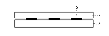
- FIG. 1 is a schematic cross-sectional view of a light modulation element 1 according to an embodiment of the present disclosure.
- 6 is a flowchart showing an example of a procedure of a method for manufacturing the light modulation element 1.
- Process drawing explaining the 1st example of the manufacturing method of the light modulation element of FIG. Process drawing following FIG. 3A.
- the process drawing following FIG. 3B The figure which shows an example of a Fourier-transform image.
- Process drawing explaining the 2nd example of the manufacturing method of the light modulation element of FIG. The process drawing following FIG. 5A.
- FIG. 5B The figure which shows the method of observing the reproduction light image of a hologram recording layer from a normal line direction.
- FIG. 5 The figure which shows the method of observing the reproduction light image of a hologram recording layer from a normal line direction.
- FIG. 6B is a diagram showing an example of the reproduced light image in FIG. 6A.
- FIG. 18 is a diagram showing a second example of a cross-sectional structure taken along line AA of the information recording medium in FIG. 17.
- FIG. 18 is a diagram showing a third example of a cross-sectional structure taken along the line AA of the information recording medium in FIG. 17.
- FIG. 18 is a diagram showing a fourth example of a cross-sectional structure taken along the line AA of the information recording medium in FIG. 17.
- FIG. 20 is a diagram showing a first example of a cross-sectional structure taken along line AA of FIG.
- FIG. 20 is a diagram showing a second example of a cross-sectional structure taken along the line AA of FIG.
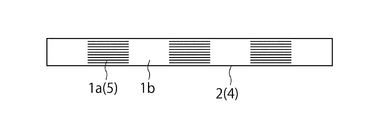
- FIG. 1 is a schematic cross-sectional view of a light modulation element 1 according to an embodiment of the present disclosure.
- the light modulation element 1 in FIG. 1 includes an optical member 2 having a light control unit 1a and a light transmission unit 1b.
- the light control unit 1a reflects or absorbs light of a specific wavelength according to a reproduction reference image for reproducing an original image, and transmits at least light of a specific wavelength in the visible light band.
- the reproduction reference image is an image having light intensity distribution and phase distribution corresponding to the original image, and is, for example, a Fourier transform image of the original image.
- the light transmission part 1b transmits light in at least the visible light band including the specific wavelength.
- the visible light band is, for example, a wavelength range of 360 to 830 nm.
- the specific wavelength is a partial wavelength band within the visible light band.
- the wavelength band of the specific wavelength of the present disclosure is a wavelength range at both ends of the half-value width of the spectral transmittance in the light control unit 1a.
- the half width of the spectral transmittance is the transmittance (%) of the optical member 2 assumed when the light control unit 1a is not formed at the wavelength where the transmittance is minimum, and the transmittance.
- the transmittance (%) of the optical member 2 at the wavelength at which the minimum value is a is defined as a
- the transmittance is (b + a) / 2
- the specific wavelength may be a green wavelength band of 495 to 570 nm. More preferably, it may be a green wavelength band of 507 to 557 nm.
- the narrower the wavelength band the higher the monochromaticity of the reconstructed light image, the less blurred the reconstructed light image due to chromatic dispersion, and the clear reconstructed light image can be observed. This is because a change in the hue of the scenery around the reproduction light image seen through the modulation element 1 is reduced.
- the optical member 2 may be a hologram recording layer 4 having a light control unit 1a and a light transmission unit 1b.
- the light control unit 1 a in the hologram recording layer 4 may be the interference fringes 5 in the hologram recording layer 4.
- the optical member 2 is more desirable as the transmittance in the visible light band is higher. Specifically, the transmittance is desirably 60% or more, and particularly desirably 70% or more. The higher the transmittance of the optical member 2, the better the visibility of the optical image by the optical member 2.
- the transmittance is a value measured according to JIS K7361-1.
- the optical member 2 is desirable as the haze value is lower.
- the haze value is preferably in the range of 0.01% to 5%, and particularly preferably in the range of 0.01% to 1.5%.
- the haze value is a value measured according to JIS K7136.
- the hologram recording layer 4 is formed by recording interference fringes 5 on a volume hologram recording material, for example.
- the interference fringes 5 correspond to the light control unit 1a.
- the hologram recording layer 4 includes a region where the interference fringes 5 are formed and a region where the interference fringes 5 are not formed, and the region where the interference fringes 5 are not formed corresponds to the light transmission portion 1b.
- the half-value width of the spectral transmittance representing the width of the specific wavelength transmitted through the hologram recording layer 4 is desirably 100 nm or less in order to improve the color discrimination performance and obtain a clear reproduced light image. More preferably, the half width is desirably 50 nm or less.
- the volume hologram recording material is not particularly limited as long as it has values within the allowable ranges of transmittance and haze value described above.
- a photosensitive material containing a silver salt material, a dichromated gelatin emulsion, a photopolymer resin, a photocrosslinkable resin, a cationic polymerizable compound, a radical polymerizable compound, a photo radical polymerization initiator system, and a photo cationic polymerization initiator system Etc. are used.
- the interference fringes 5 inside the hologram recording layer 4 are formed by making light of a specific wavelength incident on the volume hologram recording material from the first direction.
- the first direction may be a normal direction of the optical member 2.
- the optical member 2 emits light in a predetermined wavelength band including a specific wavelength from a point light source in a predetermined region partially including the interference fringes 5 in the hologram recording layer 4 along the normal direction of the optical member 2.
- a reproduction light image having a specific wavelength is visually recognized.
- the optical member 2 observes a point light source through a predetermined region from a direction inclined from the normal direction, a reproduction light image having a color shorter than the specific wavelength is visually recognized.
- the predetermined region is a region including the light control unit 1a and the light transmission unit 1b corresponding to the Fourier transform image in the hologram recording layer 4, and is a region where the reproduction light image can be visually recognized.
- the reproduction light image cannot be visually recognized only by the light control unit 1a or the light transmission unit 1b.
- the first direction described above may be a direction inclined from the normal direction of the optical member 2.
- the optical member 2 is in a normal direction of the optical member 2 in a state where light in a predetermined wavelength band including a specific wavelength is incident from a point light source on a predetermined region partially including interference fringes in the hologram recording layer 4.
- a point light source is observed through a predetermined region from a direction inclined from the center, a reproduced light image having a specific wavelength is visually recognized.
- the optical member 2 observes the point light source through a predetermined region from a direction closer to the normal direction than the inclined direction, a reproduction light image having a color longer than the specific wavelength is visually recognized.
- FIG. 2 is a flowchart showing an example of a procedure of a method for manufacturing the light modulation element 1
- FIGS. 3A to 3C are process diagrams corresponding to the procedure of FIG.
- a Fourier transform image is generated.
- the Fourier transform image is generated by performing processing such as Fourier transform on the original image using a computer. Specifically, first, an original image is generated on a personal computer (hereinafter, PC) (step S1).
- PC personal computer
- the original image is an arbitrary character, symbol, pattern, or the like.
- a Fourier transform image of the original image is generated using a computer such as a PC (step S2).
- the Fourier transform image is binarized (step S3). That is, the phase is examined for each pixel of the Fourier transform image, and when the phase is from minus 90 degrees to plus 90 degrees, a certain value Tp, for example, transparent is assigned, and in other cases, another certain value Tm, for example, black or Binarization is performed by assigning mirror surfaces.
- the range for assigning Tp may be set to a value other than minus 90 degrees and plus 90 degrees.
- FIG. 4 shows an example of the Fourier transform image 10.
- the Fourier transform image 10 of FIG. 4 is binary data of black and white, but may be composed of multi-value data having more than binary values.
- An optical image reproduced based on the Fourier transform image 10 is a point-symmetric optical image with respect to a predetermined center position.
- the binarized Fourier transform image obtained in step S3 is arranged in a desired range (step S4).
- a Fourier transform image in which four binarized Fourier transform images are arranged is generated.
- a Fourier transform image is generated by arranging, for example, 20 images of the minimum unit vertically and horizontally.
- the Fourier transform image 10 includes an image in which images of minimum units such as FIG. 4 are arranged in a desired range.
- a light absorption layer or a reflection layer is formed on the glass substrate, and a photomask substrate 7 is produced by patterning the light absorption layer or the reflection layer according to the Fourier transform image 10 (step S5).
- the white portion of the Fourier transform image 10 in FIG. 4 is a photomask on which the Fourier transform image 10 is recorded by removing the light absorption layer or reflection layer by etching and leaving the light absorption layer or reflection layer as it is in the black portion.
- a substrate 7 is produced.
- the light absorbing layer may be patterned on the film base material according to the Fourier transform image 10 by a method for producing a printing plate-making film using laser recording.
- an example using the photomask substrate 7 will be described.
- step S6 light of a specific wavelength is irradiated from both sides with the photomask substrate 7 superimposed on the volume hologram recording material 8 (step S6).
- the irradiation light coherent light L1 having the same phase and wavelength is used.
- light incident on the light absorption layer 6 in the photomask substrate 7 is absorbed and not incident on the volume hologram recording material 8.
- the light passing through the portion without the light absorption layer 6 in the photomask substrate 7 penetrates the photomask substrate 7 as it is and enters the volume hologram recording material 8. As shown in FIG.
- the light from both sides interferes to form an interference fringe 5 (step S7).
- the interference fringes 5 are formed at locations that do not overlap the light absorption layer 6 in the photomask substrate 7.
- the formation location of the light absorption layer 6 corresponds to the light transmission portion 1b.
- the light transmitting portion 1b is disposed.
- the light modulation element 1 is obtained by removing the photomask substrate 7 (step S8).
- FIG. 5A to 5C are process diagrams for explaining another example of the manufacturing method of the light modulation element 1 of FIG.
- a photomask substrate 7 is disposed below the volume hologram recording material 8, and light having a specific wavelength is incident from above the volume hologram recording material 8.
- An example using a photomask substrate will also be described with reference to FIG.
- the interference fringes 5 corresponding to the Fourier transform image 10 are formed in the volume hologram recording material 8.
- the interference fringes 5 reflect light having a specific wavelength and transmit light having a wavelength other than the specific wavelength, and correspond to the light control unit 1a.
- the light control unit 1a and the light transmission unit 1b in the region without the interference fringes 5 form a reproduction light image because light of a specific wavelength does not pass through the light control unit 1a but passes through the light transmission unit 1b.
- Light other than the wavelength is transmitted through both the light control unit 1a and the light transmission unit 1b, so that a reproduction light image is not formed. Therefore, according to the manufacturing methods of FIGS. 3A to 3C and FIGS. 5A to 5C, it is possible to visually recognize a single color reproduction light image by providing the light control unit 1a and the light transmission unit 1b.
- FIGS. 3A to 3C and FIGS. 5A to 5C show an example in which the interference fringes 5 are formed by causing the coherent light L1 to enter the photomask substrate 7 and the volume hologram recording material 8 from the normal direction.
- the interference fringes 5 may be formed by making the coherent light L1 incident from a direction inclined with respect to the normal direction.
- a dielectric multilayer film may be used.
- the light modulation element 1 is manufactured using the dielectric multilayer film, for example, after the dielectric multilayer film is laminated on the base material layer by vapor deposition or vapor phase growth method, a photomask substrate patterned according to the Fourier transform image 10 may be disposed, and the dielectric multilayer film may be patterned by an etching process using photolithography.
- a patterned dielectric multilayer film may be formed on the base material layer by an electron beam drawing method or the like instead of using a photomask substrate. In this case, a certain part of the dielectric multilayer film corresponds to the interference fringe 5 and serves as the light control unit 1a.
- the half-value width of the spectral transmittance representing the width of the specific wavelength transmitted through the patterned dielectric multilayer film is preferably 100 nm or less in order to improve the color discrimination performance and obtain a clear reproduction light image. More preferably, the half width is desirably 50 nm or less.
- the optical member 2 having a dielectric multilayer film is a normal direction of the optical member 2 in a state where light from a point light source 11 in a predetermined wavelength band including a specific wavelength is incident on a predetermined region partially including the dielectric multilayer film.
- a reproduction light image having a specific wavelength is visually recognized.
- the point light source 11 is observed through the predetermined region from a direction inclined from the normal direction, a color having a shorter wavelength than the specific wavelength is observed. A reproduced light image is visually recognized.
- the optical member 2 having a dielectric multilayer film is a method of the optical member 2 in a state where light from a point light source 11 in a predetermined wavelength band including a specific wavelength is incident on a predetermined region partially including the dielectric multilayer film.
- a reproduction light image having a specific wavelength is visually recognized, and when the point light source 11 is observed through the predetermined area from a direction closer to the normal direction than the inclined direction.
- a reproduced light image having a color longer than the specific wavelength is visually recognized.
- the light modulation element 1 selects the color of the reproduced light image to be visually recognized by controlling the incident direction and wavelength of the laser light used when forming the interference fringes 5 in the volume hologram recording material 8. be able to. Further, by controlling the interlayer distance of the dielectric multilayer film and the refractive index of each layer, it is possible to select the color of the visually reproduced light image. In addition, the color of the visually reconstructed light image changes also by changing the viewing direction.
- FIG. 6A is a diagram showing a method of observing a reproduction light image of the hologram recording layer 4 produced in FIGS. 3A to 3C or FIGS. 5A to 5C.
- light from the point light source 11 is incident on a predetermined region along the normal direction of the hologram recording layer 4, and an observer 12 is seen from the surface side opposite to the point light source 11 with respect to the hologram recording layer 4.
- the predetermined region is a region including the light control unit 1a and the light transmission unit 1b corresponding to the Fourier transform image in the hologram recording layer 4, and is a region where the reproduced light image can be visually recognized.
- the region where the interference fringes 5 are formed is the light control unit 1a, and the region where the interference fringes 5 are not formed is the light transmission unit 1b.
- the light from the point light source 11 is light in a predetermined wavelength band including a specific wavelength. As a more specific example, the light from the point light source 11 may be light of a specific wavelength or white light.
- the point light source 11 does not need to be coherent light L1, but is preferably light including a relatively wide wavelength component such as LED light or an incandescent lamp.
- the interference fringe 5 of the present embodiment is a light control unit 1a that reflects light without passing through a specific wavelength and transmits light with a wavelength other than the specific wavelength.
- the area where the interference fringes 5 are not recorded is a light transmitting portion 1b that transmits light having a specific wavelength and light having a wavelength other than the specific wavelength. Therefore, the optical member 2 reflects and transmits light corresponding to the Fourier transform image with respect to light having a specific wavelength, and only transmits light with respect to light having a wavelength other than the specific wavelength.
- the reproduced light image can be visually recognized with the color of the specific wavelength.
- FIG. 7A shows an example in which the observer 12 observes the point light source 11 through a predetermined area along a direction inclined from the normal direction of the hologram recording layer 4.
- the color of the reproduced light image that is visually recognized is shorter. Shift to the wavelength side.
- the color visually recognized from the normal direction is green
- the color of the reproduction light image becomes bluish as the inclination angle from the normal direction increases.
- the visual sensitivity of the human eye is maximum in green, and the visual sensitivity decreases as it approaches blue. Therefore, as the observation direction of the observer 12 is inclined from the normal direction, the reproduced light image is as shown in FIG. 7B. It becomes difficult to see.
- the interference fringes 5 are formed in the hologram recording layer 4 by making the coherent light L1 having a specific wavelength incident along the normal direction of the hologram recording layer 4, the direction from the direction inclined with respect to the normal direction.
- the point light source 11 is observed through a predetermined region including the region where the interference fringes 5 are formed, a color (visible when viewed from the normal direction) and shifted to a shorter wavelength side than the wavelength used for forming the interference fringes ( For example, since the color is visually recognized with a blue color), the visibility may be reduced.
- FIG. 8 is a diagram showing another example of manufacturing the interference fringes 5 in the hologram recording layer 4.
- coherent light L 1 having a specific wavelength is incident on the volume hologram recording material 8 along a direction inclined from the normal direction of the volume hologram recording material 8, and interference fringes 5 are formed inside the volume hologram recording material 8.
- the incident coherent light is compared. Even if the wavelength of the light L1 is the same, the latter has a wider pitch in the normal direction of the interference fringes 5.
- the pitch of the interference fringes 5 in the normal direction increases, and the greater the inclination angle from the normal direction, the greater the interference.
- the pitch in the normal direction of the stripes 5 becomes wider.
- FIG. 9A shows an example in which the point light source 11 is observed through a predetermined region including the formation region of the interference fringe 5 from the same direction as the incident direction of the coherent light L1 when the interference fringe 5 of FIG. 8 is formed.
- the reproduced light image is visually recognized with a color having the same wavelength as the coherent light used when the interference fringes 5 are formed.
- FIG. 10A shows an example in which the point light source 11 is observed from a normal direction of the hologram recording layer 4 on which the interference fringes 5 shown in FIG.
- the color of the reproduced light image is shifted to a color on the longer wavelength side than the predetermined wavelength.
- the color of the wavelength of the coherent light used when the interference fringe 5 is formed is green
- the point light source 11 is observed through a predetermined region along the normal direction, it is visually recognized as a reddish color, for example, orange. Since the reddish color has higher visibility than the blue color, the visibility is better than that of the blue color.
- the interference fringes 5 are formed in the volume hologram recording material 8
- the green coherent light L1 having a predetermined wavelength is not incident along the normal direction but is inclined with respect to the normal direction.
- the angle range in which the reproduced light image can be visually recognized can be widened.
- the hologram recording layer 4 when observing the reproduction light image of the interference fringes 5 formed in the hologram recording layer 4, the hologram recording layer 4 is moved from the surface side opposite to the surface side where the point light source 11 of the hologram recording layer 4 is arranged. Although the example which observes was demonstrated, you may arrange
- FIG. 1 the example which observes was demonstrated, you may arrange
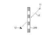
- FIG. 11A and FIG. 11B are diagrams showing an example in which the point light source 11 is arranged on the same surface side as the observer 12 and the reproduction light image is observed.
- an LED is used as the point light source 11.
- the hologram recording of the point light source 11 is performed.
- a reproduced light image can be visually recognized at a position 11a that is plane-symmetric with respect to the layer.
- FIG. 12 shows an example in which a laser pointer 11 b that emits coherent light L ⁇ b> 3 is used as the point light source 11.
- the laser pointer 11b is similarly used.
- the coherent light L1 incident on the hologram recording layer 4 along the normal direction of the hologram recording layer 4 the reproduced image 24 with a color of a predetermined wavelength is applied to the predetermined projection surface 14 on the opposite surface side of the hologram recording layer 4.
- the observer 12 can visually recognize the reproduced image 24 by observing the projection plane without passing through a predetermined region including the light control unit 1a and the light transmission unit 1b in the hologram recording layer 4.
- the example in which the interference fringe 5 that reflects the light of the specific wavelength is formed in the hologram recording layer 4 is shown.
- the light of the specific wavelength is formed on the base material layer.
- a specific wavelength absorption layer containing a specific wavelength absorbing dye that absorbs a green wavelength component which is a specific wavelength is formed on the base material layer. It may be formed in accordance with a Fourier transform image on the upper surface to be a predetermined region where the reproduced light image can be observed.
- the part with the specific wavelength absorbing dye is the light control unit 1a.
- dye becomes the light transmissive part 1b.
- the ink containing the specific wavelength absorbing dye is used as the base material layer.
- a method of forming on top of this can be considered.
- Specific materials for the specific wavelength absorbing dye include tetraazaporphyrins, cyanine dyes, azomethine dyes, rhodamine dyes and the like used in color filters and the like.
- polyethylene terephthalate, polycarbonate, acrylic resin, cycloolefin resin, polyester resin, polystyrene resin, acrylic styrene resin, or other resin films having high transmittance and low haze value, quartz glass, and the like are used.
- the half-value width of the spectral transmittance that represents the width of the specific wavelength transmitted by the specific wavelength absorbing dye formed on the base material layer is 100 nm or less in order to improve the color discrimination performance and obtain a clear reproduction light image. desirable. More preferably, the half width is desirably 50 nm or less.
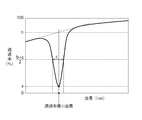
- FIG. 13 is a graph showing the spectral transmittance distribution of the light control unit 1a.
- the horizontal axis represents wavelength (nm) and the vertical axis represents transmittance (%).
- the light control unit 1a in FIG. 13 is an interference fringe 5, a dielectric multilayer film, a specific wavelength absorbing dye, or the like.
- the above-described half width (full width at half maximum) c is the transmittance (%) of the optical member 2 assumed when the light control unit 1a is not formed at the wavelength where the transmittance is minimum, and the transmittance is minimum.
- the transmittance (%) of the optical member 2 at a wavelength becomes a is defined as the difference between the wavelengths before and after the wavelength closest to the wavelength at which the transmittance is minimum, where the transmittance is (b + a) / 2. .
- the light modulation element 1 controls the incident light and the wavelength of the laser beam used when forming the interference fringes 5 in the volume hologram recording material 8 to visually recognize the reproduced light image.
- the color can be selected. Therefore, when two or more types of laser beams having different wavelengths are used when forming the interference fringes 5, reproduction light images of two or more types of colors can be visually recognized.
- FIG. 14 shows an example of a reproduced light image including two different colors.
- the letters “F” with different shades in FIG. 14 actually represent different colors. More specifically, for example, red “F” 31 and green “F” 32 are arranged diagonally.
- the light modulation element 1 capable of reproducing the reproduction light image of FIG. 14 can be manufactured by the procedure shown in FIG. 2 and FIGS. 3A to 3C. More specifically, a volume hologram capable of obtaining a red reproduction light image using the red “F” photomask substrate 7, and a green color using the green “F” photomask substrate 7.
- a volume hologram from which a reproduction light image can be obtained is produced, and the hologram recording layer 4 in which these two volume holograms are laminated is irradiated with a laser beam containing red and green wavelength components, whereby a red and green reproduction light image is obtained. Can be obtained.
- an interference fringe is formed in the hologram recording material 8 by irradiating a laser beam containing a red wavelength component, and then the arrangement of the photomask substrate 7 is arranged.
- Another interference fringe may be formed in the hologram recording material 8 by irradiating a laser beam containing a green wavelength component with the direction shifted.
- the light control unit 1a in the light modulation element 1 for obtaining the reproduced light image of FIG. 14 transmits light in a predetermined wavelength band including two wavelengths from the point light source as interference fringes in the hologram recording layer 4.
- the point light source is observed through the predetermined region from the normal direction of the optical member 2 in a state where it is incident on a predetermined predetermined region, two different reproduction light images are visually recognized.
- FIG. 15A shows a first example of a reproduced light image of the light modulation element 1 manufactured using three or more laser beams having different wavelengths.
- the reproduced light image in FIG. 15A represents white “F” 33.
- the reproduction light image has three or more formed in the light modulation element 1 when the light modulation element 1 is irradiated with reproduction illumination light including all wavelength components of the three or more laser beams used at the time of production.
- the light diffracted by each of the interference fringes is mixed with each other, and as a result, it is observed in white.
- the light modulation element 1 for obtaining the reproduction light image of FIG. 15A prepares, for example, three or more photomask substrates 7 corresponding to each of three or more wavelength components, and sets the photomask substrate 7 for each wavelength. Three or more interference fringes may be formed in the volume hologram recording medium 8 while changing.
- a plurality of volume holograms can be produced by which a plurality of color reproduction light images can be obtained using a plurality of photomask substrates 7 corresponding to each of three or more wavelength components, and these volume holograms can be laminated. Good.
- a white reproduction light image can be obtained by simultaneously irradiating the laminated hologram recording layer 4 with laser light having the same wavelength as that used during recording.
- the wavelength range of the laser beam used to obtain the white reproduction light image may be three or more laser beams of the red, green, and blue wavelength ranges, or other wavelength ranges. Three or more laser beams may be used.
- the light control unit 1a in the light modulation element 1 for obtaining the reproduction light image in FIG. 15A causes the light in the predetermined wavelength band including three or more wavelengths to interfere with the light in the hologram recording layer 4 from the point light source.
- the point light source is observed through the predetermined region from the normal direction of the optical member 2 in a state where the light is incident on the predetermined region partially including the stripe, a white reproduction light image is visually recognized.
- FIG. 15B shows a second example of a reproduction light image of the light modulation element 1 manufactured using three or more laser beams having different wavelengths.
- the reproduced light image in FIG. 15B is color-coded by three or more colors.
- the regions with different shading in FIG. 15B indicate that the colors are different.
- the light modulation element 1 in FIG. 15B is produced by using three photomask substrates 7 corresponding to three colors to produce three volume holograms for obtaining a reproduction light image of a plurality of colors, and laminating these volume holograms. is there.
- a plurality of reproduction light images illuminated with one or more colors can be obtained.
- the light modulation element 1 of FIG. 15B forms interference fringes in the volume hologram recording medium 8 by irradiating laser light having a different wavelength for each placement position while shifting the placement location of one photomask substrate 7. May be.
- the light control unit 1a in the light modulation element 1 for obtaining the reproduction light image of FIG. 15B transmits light in a predetermined wavelength band including three or more wavelengths from the point light source to the interference in the hologram recording layer 4.
- a point light source is observed through a predetermined region from the normal direction of the optical member 2 in a state where it is incident on a predetermined region partially including a stripe, a reproduction light image colored in three or more colors is visually recognized It is.
- the light modulation element 1 according to the present embodiment can be combined with an existing light modulation element that highlights a two-dimensional or three-dimensional reproduced light image.
- the hologram recording layer 4 on which the interference fringes 5 of the present embodiment are recorded and the existing hologram recording layer that causes a two-dimensional or three-dimensional reproduction light image (also called a Lippmann hologram reproduction image) to emerge are laminated.
- an interference fringe in the existing hologram recording layer that causes a two-dimensional or three-dimensional reproduction light image to emerge is formed in the hologram recording layer 4 according to the present embodiment separately or simultaneously with the interference fringe 5. May be.
- the light modulation element 1 reproduces not only the hologram recording layer 4 produced by the procedures of FIGS. 2 and 3A to 3C (or FIGS. 5A to 5C) but also a Lippmann hologram reproduction image.
- the interference fringes may be provided.
- the interference fringes for reproducing the Lippmann hologram reproduction image may be formed on the hologram recording layer 4 on which the interference fringes for reproducing the reproduction light image corresponding to the reproduction reference image such as a Fourier transform image are formed, It may be formed in a recording material layer different from the hologram recording layer 4.
- FIG. 16A and FIG. 16B are diagrams for explaining a reproduction method of this type of light modulation element 1.
- the reproduction illumination light for reproducing the reproduction light image 34 corresponding to the reproduction reference image is different from the reproduction illumination light for reproducing the Lippmann hologram reproduction image 35. More specifically, the reproduction illumination light for reproducing the reproduction light image 34 corresponding to the reproduction reference image is a point light source arranged away from one main surface of the light modulation element 1 as shown in FIG. 16A. It is the light from 11a. The observer observes the reproduction light image 34 from the surface side opposite to the one main surface of the light modulation element 1 with the point light source 11a turned on. On the other hand, as shown in FIG.
- the reproduction illumination light for reproducing the Lippmann hologram reproduction image 35 is, for example, from another point light source 11b arranged at a position separated from one main surface of the light modulation element 1. Irradiated in a direction inclined with respect to the normal direction of the main surface. The observer observes the Lippmann hologram reproduction image 35 from the normal direction of one main surface.
- the Lippmann hologram reproduction image 35 is visible not only with the point light source 11b but also with another illumination light source such as a fluorescent lamp.
- the Lippmann hologram reproduction image 35 is illuminated with light irradiated in a direction inclined with respect to the normal direction of one principal surface, and is observed from the normal direction, that is, the observer is from a direction deviating from the direction of the light source.
- the reproduction light image 34 corresponding to the reproduction reference image can be observed from the direction of the point light source. Therefore, there is no fear that the Lippmann hologram reproduction image 35 and the reproduction light image 34 corresponding to the reproduction reference image are mixed and observed, and both reproduction images can be clearly distinguished and observed.
- the reproduction illumination light for reproducing the Lippmann hologram reproduction image 35 may be the point light source 11b or another illumination light source as described above.
- the point light source 11a it is necessary to place the point light source 11a on the side opposite to the observer with the light modulation element 1 interposed therebetween.
- the reproduced light image 34 can be reproduced even when the observer observes from the same side as the point light source 11a. In this case, from the specular reflection direction of the light from the point light source 11a. The observer needs to observe.
- the reproduction light image 34 is used for security purposes such as forgery prevention.
- the original for reproducing the Lippmann hologram reproduction image 35 is produced, for example, by the existing two-step method (also called the H1H2 method).
- a volume hologram can be formed by stacking an original produced by the H1H2 method on a photomask substrate and irradiating a laser beam with a predetermined wavelength from a predetermined direction.
- an interference fringe is formed in the volume hologram recording medium 8 using an original produced by the H1H2 method, and the procedure of FIG. 3A to FIG. 3C or FIG. 5A to FIG. 5C is performed using the formed volume hologram recording medium 8
- the final hologram recording layer 4 may be formed.
- the color of the Lippmann hologram reproduction image 35 can be controlled by the wavelength of the laser beam when forming the interference fringes.
- the reproduction illumination light irradiated when reproducing the Lippmann hologram reproduction image 35 needs to include the wavelength component of the reference light used when forming the interference fringes.
- the wavelength of the laser light used when forming the interference fringes corresponding to the reproduction light image 34 corresponding to the reproduction reference image and the laser light used when forming the interference fringes corresponding to the Lippmann hologram reproduction image 35 are obtained.
- the reproduction light image 34 and the Lippmann hologram reproduction image 35 corresponding to the reproduction reference image can be made the same color or different from each other.
- the color type can be arbitrarily adjusted.
- FIG. 17 is a diagram illustrating an example of the information recording medium 20.
- the information recording medium 20 in FIG. 17 is a medium on which various information such as personal information such as banknotes, ID certificates, passports, cash vouchers, tickets, and public documents, and confidential information is recorded, or a medium having a monetary value.
- the ID card is a national ID card, a license, a membership card, an employee card, a student card, or the like.
- the substrate of the medium in FIG. 17 is paper, resin, metal, synthetic fiber, or the like. The substrate of FIG.
- the 17 is provided with an opening 21, and at least a part of the opening 21 is provided with a transparent member 22 in which security information such as characters, symbols, and patterns is recorded as a Fourier transform image. .
- the entire area of the opening 21 may be covered with the transparent member 22, or the transparent member 22 may be disposed only on a part of the opening 21.
- the transparent member 22 corresponds to the light modulation element 1 according to the present embodiment.
- a point light source is arranged on the back surface side of the information recording medium 20 in FIG. 17, and the observer observes the point light source through the transparent member 22 from the front surface side, whereby the security information recorded on the transparent member 22 is obtained. It can be visually recognized.
- This security information can be used, for example, for authenticity determination of the information recording medium 20.
- FIG. 18A is a diagram showing a first example of a cross-sectional structure taken along line AA of the information recording medium 20 of FIG.
- the opaque resin layer 32 is disposed on the transparent resin layer 31.
- the opaque resin layer 32 is provided with an opening 33 in a region overlapping with the opening 21.
- the light modulation element 1 described above is disposed on the opening 33, and the transparent resin layer 34 is disposed thereon. Thereby, the reproduction image according to the Fourier transform image formed in the light modulation element 1 can be visually recognized by illuminating the opening 21 with light from the point light source.
- the opening 33 may be formed by making a hole in the opaque resin layer 32, or after making a hole in the opaque resin layer 32, a transparent resin layer having the same shape as the hole is formed in the hole. May be. 18A shows that there is a gap between the transparent resin layer 34 and the opaque resin layer 32, but when used as the information recording medium 20, the transparent resin layer 34 and the transparent resin layer 34 are exposed to heat and pressure. The opaque resin layer 32 is fused, or the transparent resin layer 34 and the opaque resin layer 32 are bonded via an adhesive (not shown).
- FIG. 18B is a diagram showing a second example of a cross-sectional structure taken along line AA of the information recording medium 20 of FIG.
- the information recording medium 20 shown in FIG. 18B is different from FIG. 18A in that a printing layer 35 is disposed on the back side of the transparent resin layer 34.
- the print layer 35 is disposed on the back surface of the transparent resin layer 34 so as not to overlap with the opening 21. That is, the opening 21 is provided at a location overlapping the portion where the print layer 35 is not disposed.
- the print layer 35 may be provided on the upper surface side instead of the back surface side of the transparent resin layer 34.
- the transparent resin layer 34 and the opaque resin layer 32 may be fused by applying heat and pressure, or may be bonded via an adhesive (not shown).
- FIG. 18C is a diagram showing a third example of a cross-sectional structure taken along line AA of the information recording medium 20 of FIG.
- the opaque resin layer 32 is disposed on the transparent resin layer 31, and the transparent resin layer 34 is disposed thereon.
- the light modulation element 1 is arranged in accordance with the position of the opening 21.
- the opaque resin layer 32 is provided with an opening 33 in a region overlapping with the opening 21.
- FIG. 18D is a diagram showing a fourth example of a cross-sectional structure taken along line AA of the information recording medium 20 of FIG.
- the print layer 36 is disposed on the transparent resin layer 31 so as to avoid a region overlapping the opening 21.
- a transparent resin layer 34 is disposed on the print layer 36, and a print layer 37 is disposed on the transparent resin layer 34 so as to avoid a region overlapping the opening 21.
- a transparent resin layer 38 is disposed on the printing layer 37, and the light modulation element 1 is disposed on the transparent resin layer 38 according to the position of the opening 21. That is, the opening 21 is provided at a location overlapping the portion where the print layers 36 and 37 are not disposed.
- the transparent resin layers 31, 34, 38 may be fused by applying heat and pressure, or may be bonded via an adhesive (not shown).
- FIG. 19 is a diagram showing another example of the information recording medium 20.
- the information recording medium 20 in FIG. 19 is a bill.
- the banknote of FIG. 19 is provided with an opening 21. At least a part of the opening 21 is provided with a transparent member 22 that records security information such as characters, symbols, and patterns as a Fourier transform image.
- FIG. 20A is a diagram showing a first example of a cross-sectional structure taken along line AA of FIG.
- a print layer 42 is disposed so as to avoid a region overlapping the opening 21.
- the light modulation element 1 is disposed in a region overlapping the opening 21.
- a transparent resin layer 43 is disposed on the light modulation element 1.
- a print layer 44 is disposed so as to avoid a region overlapping with the opening 21. That is, the opening 21 is provided at a location overlapping the portion where the print layers 42 and 44 are not disposed.
- the transparent resin layers 41 and 43 may be fused by applying heat and pressure, or may be bonded via an adhesive (not shown).
- 20B is a diagram showing a second example of the cross-sectional structure taken along the line AA of FIG.
- Print layers 42 and 44 are disposed on the back surface side and the top surface side of the transparent resin layer 41 so as not to overlap the opening 21.
- the light modulation element 1 is disposed in a region overlapping the opening on the upper surface side of the transparent resin layer 41. That is, the opening 21 is provided at a location overlapping the portion where the print layers 42 and 44 are not disposed.
- the light modulation element 1 according to the present embodiment can be determined with the naked eye by only a small point light source 11 such as an easily available LED light. Further, the light modulation element 1 according to the present embodiment has a feature that authenticity can be determined by confirming a reproduction light image of a color of a specific wavelength, unlike the conventional rainbow color. Furthermore, the light modulation element 1 according to the present embodiment has a feature that the color of the reproduced light image changes by changing the incident direction of the point light source 11 to the light modulation element 1, and the authenticity determination can be more reliably performed. Can do.
- the light modulation element 1 according to the present embodiment has a narrow half-value width of the spectral transmittance of the optical member 2 of 100 nm or less, more preferably 50 nm or less, the reproduced light image is clear and easy to visually check, and authenticity can be easily determined. It has the feature of being. Further, since the light modulation element 1 according to the present embodiment has a high transmittance, it is easy to observe the scene ahead through the opening 21 of the information recording medium 20.
- this embodiment includes the optical member 2 having the light control unit 1a and the light transmission unit 1b corresponding to the Fourier transform image 10 of the original image, and the light control unit 1a reflects light of a specific wavelength.
- a point light source 11 is used to reproduce a reproduction light image when a predetermined region including the light control unit 1a and the light transmission unit 1b in the optical member 2 is observed.
- the color becomes a single color, making it easier to visually recognize the reproduced light image. That is, since the light modulation element 1 according to the present embodiment has little wavelength dispersion of the reproduction light image, the outline of the reproduction light image becomes clear and a clear reproduction light image can be visually recognized.
- the color of the reproduced light image is controlled by adjusting the incident direction and wavelength of the coherent light L1 used when forming the interference fringes 5 in the hologram recording layer 4 constituting the optical member 2.
- the angle range in which the reproduced light image can be clearly seen can be controlled.
- the point light source 11 when observing the reproduction light image, may be disposed on the surface opposite to the viewer 12 with respect to the optical member 2, or the same surface side as the viewer 12.
- the point light source 11 may be arranged in the position, and the degree of freedom with respect to the location of the point light source 11 is increased.
Abstract
点光源からの光を利用して光学部材を観察する際に、所望の色で再生光像を視認できるようにする。光変調素子1は、原画像を再生するための再生基準像に応じて、特定波長の光を反射または吸収して少なくとも可視光帯域の光のうち特定波長以外の光を透過させる光制御部1aと、特定波長を含む少なくとも可視光帯域の光を透過させる光透過部1bと、を有する光学部材2を備える。
Description
本開示は、光変調素子と、それを利用した情報記録媒体に関する。
点光源からの光をフーリエ変換ホログラムに照射して、光像を生成する技術が提案されている(特開2004-126535号公報、特開2016-85355号公報、特開平10-153943号公報参照)。点光源を照射すると、点光源の照射位置の周囲に光像が浮かび上がって視認されるため、例えばセキュリティ情報を光像として浮かび上がらせることにより、真贋判定などに利用できる。
特開平10-153943号公報には、原画像のフーリエ変換像を計算機を用いて生成して二値化し、二値化されたフーリエ変換像を透明と黒のパターンとしてフィルム上に複数個配列して作製した光変調素子であるフーリエ変換ホログラムが開示されている。光像を再生するには、フィルムの後方に点光源を配置し、フィルムを通して点光源を観察する。すると、フィルム内のフーリエ変換像に対応して、点光源の周囲に点対称である画像を視認することができる。
ところが、再生時に、複数の波長成分を含む白色光をフーリエ変換ホログラムに照射すると、再生光像が波長分散された虹色で観察されるという問題があった。特に、再生光像のサイズが小さい場合には、波長分散された虹色で観察されると、再生光像の視認性が低下してしまう。したがって、再生光像が文字や記号を表している場合、波長分散によって文字や記号を正しく識別できないおそれがある。
本開示は、上述した課題を解決するためのものであり、その目的は、点光源からの光を利用して光学部材を観察したときに、所望の色で再生光像を視認可能な光変調素子および情報記録媒体を提供することである。
上記の課題を解決するために、本開示による一態様では、原画像を再生するための再生基準像に応じて、特定波長の光を反射または吸収して少なくとも可視光帯域の光のうち前記特定波長以外の光を透過させる光制御部と、前記特定波長を含む少なくとも可視光帯域の光を透過させる光透過部と、を有する光学部材を備える、光変調素子が提供される。
再生基準像は、原画像のフーリエ変換像であってもよい。
前記光学部材は、ホログラム記録層を有し、
前記光制御部は、前記ホログラム記録層内の干渉縞であってもよい。
前記光制御部は、前記ホログラム記録層内の干渉縞であってもよい。
前記光学部材は、点光源から、前記特定波長を含む所定波長帯域の光を前記ホログラム記録層内の前記干渉縞を一部に含む所定領域に入射した状態で、前記光学部材の法線方向から前記所定領域を通して前記点光源を観察すると、前記特定波長の色の再生光像が視認され、前記法線方向から傾斜した方向から前記所定領域を通して前記点光源を観察すると、前記特定波長よりも短波長の色の再生光像が視認されてもよい。
前記光学部材は、点光源から、前記特定波長を含む所定波長帯域の光を前記ホログラム記録層内の前記干渉縞を一部に含む所定領域に入射した状態で、前記光学部材の法線方向から傾斜した方向から前記所定領域を通して前記点光源を観察すると、前記特定波長の色の再生光像が視認され、前記傾斜した方向よりも前記法線方向に近い方向から前記所定領域を通して前記点光源を観察すると、前記特定波長よりも長波長の色の再生光像が視認されてもよい。
前記光学部材は、
基材層と、
前記基材層の上に積層される誘電体多層膜と、を有し、
前記光制御部は、前記誘電体多層膜であってもよい。
基材層と、
前記基材層の上に積層される誘電体多層膜と、を有し、
前記光制御部は、前記誘電体多層膜であってもよい。
前記光学部材は、点光源から、前記特定波長を含む所定波長帯域の光を前記誘電体多層膜を一部に含む所定領域に入射した状態で、前記光学部材の法線方向から前記所定領域を通して前記点光源を観察すると、前記特定波長の色の再生光像が視認され、前記法線方向から傾斜した方向から前記所定領域を通して前記点光源を観察すると、前記特定波長よりも短波長の色の再生光像が視認されてもよい。
前記光学部材は、点光源から、前記特定波長を含む所定波長帯域の光を前記誘電体多層膜を一部に含む所定領域に入射した状態で、前記光学部材の法線方向から傾斜した方向から前記所定領域を通して前記点光源を観察すると、前記特定波長の色の再生光像が視認され、前記傾斜した方向よりも前記法線方向に近い方向から前記所定領域を通して前記点光源を観察すると、前記特定波長よりも長波長の色の再生光像が視認されてもよい。
前記光学部材は、
基材層と、
前記基材層の上に積層される特定波長吸収層と、を有し、
前記光制御部は、前記特定波長吸収層であってもよい。
基材層と、
前記基材層の上に積層される特定波長吸収層と、を有し、
前記光制御部は、前記特定波長吸収層であってもよい。
前記光学部材は、点光源から前記特定波長を含む所定波長帯域の光を前記特定波長吸収層を一部に含む所定領域に入射させた状態で、前記所定領域を通して前記点光源を観察すると、前記特定波長の色の再生光像が視認されてもよい。
点光源から、前記光学部材の法線方向に沿って、前記特定波長を含む所定波長帯域の光が前記光学部材に入射された場合における前記特定波長の分光透過率の半値幅は、100nm以下であってもよい。
上述した光変調素子を備える情報記録媒体が提供されてもよい。
前記原画像は、文字、記号、絵柄などの情報を含んでいてもよい。
所定サイズの開口部を有する基材を備え、
前記光変調素子の少なくとも一部は、前記開口部に配置されてもよい。
前記光変調素子の少なくとも一部は、前記開口部に配置されてもよい。
本開示によれば、点光源からの光を利用して光学部材を観察したときに、所望の色で再生光像を視認できる。
以下、図面を参照して本開示の一実施の形態について説明する。なお、本件明細書に添付する図面においては、図示と理解のしやすさの便宜上、適宜縮尺および縦横の寸法比等を、実物のそれらから変更し誇張してある。
さらに、本明細書において用いる、形状や幾何学的条件並びにそれらの程度を特定する、例えば、「平行」、「直交」、「同一」等の用語や長さや角度の値等については、厳密な意味に縛られることなく、同様の機能を期待し得る程度の範囲を含めて解釈することとする。
図1は本開示の一実施形態による光変調素子1の模式的な断面図である。図1の光変調素子1は、光制御部1aと光透過部1bとを有する光学部材2を備えている。光制御部1aは、原画像を再生するための再生基準像に応じて、特定波長の光を反射または吸収するとともに、少なくとも可視光帯域のうち特定波長以外の光を透過させる。再生基準像とは、原画像に応じた光の強度分布や位相分布を有する像であり、例えば原画像のフーリエ変換像である。光透過部1bは、特定波長を含む少なくとも可視光帯域の光を透過させる。
可視光帯域とは、例えば360~830nmの波長範囲である。特定波長とは、可視光帯域内の一部の波長帯域である。本開示の特定波長の波長帯域とは、光制御部1aにおける分光透過率の半値幅の両端の波長範囲である。分光透過率の半値幅は、後述するように、透過率が最小となる波長において、光制御部1aが形成されていないときに想定される光学部材2の透過率(%)をb、透過率が最小となる波長における光学部材2の透過率(%)をaとしたときに、透過率が(b+a)/2となる、透過率が最小となる波長に最も近い前後の波長の差として定義される。具体的な一例としては、特定波長は、495~570nmの緑色の波長帯域であってもよい。さらに好ましくは、507~557nmの緑色の波長帯域であってもよい。波長帯域が狭いほど、再生光像の単色性が高まり、色分散による再生光像のぼけが減り、鮮明な再生光像を観察可能となるのに加え、透過する波長範囲が増えることにより、光学変調素子1を通して見た、再生光像の周囲の景色の色合いの変化が少なくなるためである。
可視光帯域とは、例えば360~830nmの波長範囲である。特定波長とは、可視光帯域内の一部の波長帯域である。本開示の特定波長の波長帯域とは、光制御部1aにおける分光透過率の半値幅の両端の波長範囲である。分光透過率の半値幅は、後述するように、透過率が最小となる波長において、光制御部1aが形成されていないときに想定される光学部材2の透過率(%)をb、透過率が最小となる波長における光学部材2の透過率(%)をaとしたときに、透過率が(b+a)/2となる、透過率が最小となる波長に最も近い前後の波長の差として定義される。具体的な一例としては、特定波長は、495~570nmの緑色の波長帯域であってもよい。さらに好ましくは、507~557nmの緑色の波長帯域であってもよい。波長帯域が狭いほど、再生光像の単色性が高まり、色分散による再生光像のぼけが減り、鮮明な再生光像を観察可能となるのに加え、透過する波長範囲が増えることにより、光学変調素子1を通して見た、再生光像の周囲の景色の色合いの変化が少なくなるためである。
光学部材2は、光制御部1aと光透過部1bを有するホログラム記録層4であってもよい。ホログラム記録層4における光制御部1aは、ホログラム記録層4内の干渉縞5であってもよい。光学部材2は、可視光帯域における透過率が高いほど望ましい。具体的には、透過率は60%以上が望ましく、とりわけ70%以上が望ましい。光学部材2の透過率が高いほど、光学部材2による光像の視認性がよくなる。ここで、透過率とは、JIS K7361-1により測定した値である。
また、光学部材2は、ヘイズ値が低いほど望ましい。具体的には、ヘイズ値が0.01%~5%の範囲内の値が望ましく、とりわけ0.01%~1.5%の範囲内の値が望ましい。光学部材2のヘイズ値が小さいほど、光学部材2による光像の視認性がよくなる。ここで、ヘイズ値とは、JIS K7136に準拠して測定した値である。
ホログラム記録層4は、例えば、体積ホログラム記録材料に干渉縞5を記録したものである。この場合、干渉縞5が光制御部1aに相当する。ホログラム記録層4は、干渉縞5が形成された領域と、干渉縞5が形成されていない領域とを含んでおり、干渉縞5が形成されていない領域が光透過部1bに相当する。ホログラム記録層4を透過する特定波長の幅を表す分光透過率の半値幅は、色の識別性能を向上させ、鮮明な再生光像を得るためには100nm以下が望ましい。さらに好ましくは、半値幅は50nm以下が望ましい。
体積ホログラム記録材料としては、上述した透過率とヘイズ値の許容範囲内の値を有するものであれば、特に限定されない。例えば、銀塩材料、重クロム酸ゼラチン乳剤、光重合成樹脂、光架橋性樹脂、カチオン重合性化合物、ラジカル重合性化合物、光ラジカル重合開始剤系および光カチオン重合開始剤系を含有する感光材料などが用いられる。
ホログラム記録層4の内部の干渉縞5は、体積ホログラム記録材料に第1方向から特定波長の光を入射させることで形成される。第1方向は、光学部材2の法線方向であってもよい。この場合、光学部材2は、点光源から、特定波長を含む所定波長帯域の光を光学部材2の法線方向に沿って、ホログラム記録層4内の干渉縞5を一部に含む所定領域に入射した状態で、光学部材2の法線方向から所定領域を通して点光源を観察すると、特定波長の色の再生光像が視認される。また、光学部材2は、法線方向から傾斜した方向から所定領域を通して点光源を観察すると、特定波長よりも短波長の色の再生光像が視認される。
ここで、所定領域とは、ホログラム記録層4内のフーリエ変換像に応じた光制御部1aと光透過部1bとを含む領域であり、再生光像を視認可能な領域である。光制御部1aだけや光透過部1bだけでは、再生光像を視認することはできない。
上述した第1方向は、光学部材2の法線方向から傾斜した方向であってもよい。この場合、光学部材2は、点光源から、特定波長を含む所定波長帯域の光をホログラム記録層4内の干渉縞を一部に含む所定領域に入射した状態で、光学部材2の法線方向から傾斜した方向から所定領域を通して点光源を観察すると、特定波長の色の再生光像が視認される。
また、光学部材2は、傾斜した方向よりも法線方向に近い方向から所定領域を通して点光源を観察すると、特定波長よりも長波長の色の再生光像が視認される。
また、光学部材2は、傾斜した方向よりも法線方向に近い方向から所定領域を通して点光源を観察すると、特定波長よりも長波長の色の再生光像が視認される。
図1の光変調素子1の作製方法として、複数の作製方法が考えられる。以下では、代表的な2つの作製方法を順に説明する。
図2は光変調素子1の作製方法の手順の一例を示すフローチャート、図3A~図3Cは図2の手順に対応する工程図である。まず、フーリエ変換像を生成する。フーリエ変換像は、計算機を用いて原画像に対してフーリエ変換等の処理を行うことで生成される。具体的には、まず、パーソナルコンピュータ(以下、PC)上で原画像を生成する(ステップS1)。原画像は、任意の文字、記号、絵柄などである。
次に、原画像のフーリエ変換像をPC等の計算機を用いて生成する(ステップS2)。
次に、フーリエ変換像を二値化する(ステップS3)。すなわち、フーリエ変換像の1画素ごとにその位相を調べ、位相がマイナス90度からプラス90度の場合、ある値Tp、例えば透明を割り当て、それ以外の場合、別のある値Tm、例えば黒や鏡面を割り当てることにより、二値化を行う。Tpを割当てる範囲をマイナス90度からプラス90度以外に設定してもよい。
次に、フーリエ変換像を二値化する(ステップS3)。すなわち、フーリエ変換像の1画素ごとにその位相を調べ、位相がマイナス90度からプラス90度の場合、ある値Tp、例えば透明を割り当て、それ以外の場合、別のある値Tm、例えば黒や鏡面を割り当てることにより、二値化を行う。Tpを割当てる範囲をマイナス90度からプラス90度以外に設定してもよい。
図4はフーリエ変換像10の一例を示している。図4のフーリエ変換像10は、黒と白の2値データであるが、2値より多い多値データで構成してもよい。フーリエ変換像10に基づいて再生される光像は、所定の中心位置に対して点対称な光像になる。次に、ステップS3で得られた二値化されたフーリエ変換像を所望の範囲に配列する(ステップS4)。例えば、二値化されたフーリエ変換像を4つ並べたフーリエ変換像を生成する。なお、実際には最小単位の画像を例えば縦、横に20個ずつ配列するなどして、フーリエ変換像を生成する。以降の説明では、フーリエ変換像10とは、図4などの最小単位の画像を所望の範囲に配列した画像を含むものとする。
次に、ガラス基板上に光吸収層または反射層を形成して、この光吸収層または反射層をフーリエ変換像10に応じてパターニングしたフォトマスク基板7を作製する(ステップS5)。例えば、図4のフーリエ変換像10の白部分はエッチングにより光吸収層または反射層を除去し、黒部分はそのまま光吸収層または反射層を残すことで、フーリエ変換像10が記録されたフォトマスク基板7を作製する。フォトマスク基板7を作製する代わりに、レーザ記録を用いた印刷用製版フィルムの製造方法にて、フィルム基材上に光吸収層をフーリエ変換像10に応じてパターニングしてもよい。以下では、フォトマスク基板7を用いる例を説明する。
次に、図3Aおよび図3Bに示すように、体積ホログラム記録材料8にフォトマスク基板7を重ね合わせた状態で、両面側から特定波長の光を照射する(ステップS6)。照射光としては、位相および波長が揃っているコヒーレント光L1が用いられる。照射光のうち、フォトマスク基板7内の光吸収層6に入射された光は吸収されて、体積ホログラム記録材料8には入射されない。フォトマスク基板7内の光吸収層6のない箇所を通過する光は、そのままフォトマスク基板7を突き抜けて、体積ホログラム記録材料8に入射される。図3Bに示すように、体積ホログラム記録材料8内の光吸収層6と重ならない箇所では、両面側からの光が干渉して、干渉縞5が形成される(ステップS7)。この干渉縞5は、フォトマスク基板7内の光吸収層6と重なり合わない箇所に形成される。光吸収層6の形成箇所が光透過部1bに相当する。体積ホログラム記録材料8内の面方向に隣接する干渉縞5の間には光透過部1bが配置されることになる。次に、図3Cに示すように、フォトマスク基板7を除去することで、光変調素子1が得られる(ステップS8)。
図5A~図5Cは図1の光変調素子1の作製方法の他の一例を説明する工程図である。
まず、図5Aに示すように、図3と異なり、体積ホログラム記録材料8の下方にフォトマスク基板7を配置して、体積ホログラム記録材料8の上方から特定波長の光を入射させる。第2例では、体積ホログラム記録材料8の下方から光を入射する必要はない。図5においても、フォトマスク基板を用いる例を説明する。
まず、図5Aに示すように、図3と異なり、体積ホログラム記録材料8の下方にフォトマスク基板7を配置して、体積ホログラム記録材料8の上方から特定波長の光を入射させる。第2例では、体積ホログラム記録材料8の下方から光を入射する必要はない。図5においても、フォトマスク基板を用いる例を説明する。
図5A~図5Cの例において、体積ホログラム記録材料8に入射された特定波長の光(入射光)は、フォトマスク基板7内の光反射層16に入射されると、反射して上方に進行する。この反射光と入射光が互いに干渉して、図5Bに示すように体積ホログラム記録材料8内に干渉縞5が形成される。一方、体積ホログラム記録材料8内の光反射層16のない箇所に入射された光は、他の光と干渉することなく、体積ホログラム記録材料8とフォトマスク基板7を通過するため、干渉縞を形成しない。よって、体積ホログラム記録材料8内の干渉縞5は、フォトマスク基板7内の光反射層16と重なる箇所に形成される。その後、フォトマスク基板7を除去することで、図5Cに示すような光変調素子1が得られる。
図3A~図3Cと図5A~図5Cのいずれの作製方法においても、フーリエ変換像10に応じた干渉縞5が体積ホログラム記録材料8内に形成される。この干渉縞5は、特定波長の光を反射するとともに、特定波長以外の光を透過させるものであり、光制御部1aに相当する。この光制御部1aと、干渉縞5のない領域の光透過部1bとによって、特定波長の光は光制御部1aは透過せず光透過部1bは透過するため再生光像を形成し、特定波長以外の光は光制御部1aも光透過部1bも透過するため再生光像を形成しないため、再生光像が虹色に視認されなくなる。よって、図3A~図3Cと図5A~図5Cの作製方法によれば、光制御部1aと光透過部1bを設けることで、単一色の再生光像を視認することができる。
図3A~図3Cと図5A~図5Cでは、法線方向からコヒーレント光L1をフォトマスク基板7と体積ホログラム記録材料8に入射させて干渉縞5を形成する例を示したが、後述するように、法線方向に対して傾斜した方向からコヒーレント光L1を入射させて干渉縞5を形成してもよい。
なお、体積ホログラム記録材料8を用いる代わりに、誘電体多層膜を用いてもよい。誘電体多層膜を用いて光変調素子1を作製する場合は、例えば、基材層の上に、蒸着や気相成長法等により、誘電体多層膜を積層した後、誘電体多層膜の上に、フーリエ変換像10に応じてパターニングされたフォトマスク基板を配置し、フォトリソグラフィによるエッチング処理にて、誘電体多層膜をパターニングすればよい。あるいは、フォトマスク基板を用いる代わりに電子線描画法などにより、基材層上に、パターニングされた誘電体多層膜を形成してもよい。この場合、誘電体多層膜のある部分が干渉縞5に相当し、光制御部1aとなる。また、誘電体多層膜のない部分が光透過部1bとなる。パターニングされた誘電体多層膜を透過する特定波長の幅を表す分光透過率の半値幅は、色の識別性能を向上させ、鮮明な再生光像を得るためには100nm以下が望ましい。さらに好ましくは、半値幅は50nm以下が望ましい。
誘電体多層膜を有する光学部材2は、点光源11から、特定波長を含む所定波長帯域の光を誘電体多層膜を一部に含む所定領域に入射した状態で、光学部材2の法線方向から所定領域を通して点光源11を観察すると、特定波長の色の再生光像が視認され、法線方向から傾斜した方向から所定領域を通して点光源11を観察すると、特定波長よりも短波長の色の再生光像が視認される。
あるいは、誘電体多層膜を有する光学部材2は、点光源11から、特定波長を含む所定波長帯域の光を誘電体多層膜を一部に含む所定領域に入射した状態で、光学部材2の法線方向から傾斜した方向から所定領域を通して点光源11を観察すると、特定波長の色の再生光像が視認され、傾斜した方向よりも法線方向に近い方向から所定領域を通して点光源11を観察すると、特定波長よりも長波長の色の再生光像が視認される。
本実施形態による光変調素子1は、体積ホログラム記録材料8内に干渉縞5を形成する際に用いるレーザ光の入射方向や波長を制御することで、視認される再生光像の色を選択することができる。また、誘電体多層膜の層間距離や各層の屈折率を制御することで、視認される再生光像の色を選択することができる。また、観察方向を変えることによっても、視認される再生光像の色が変化する。
上述した図3A~図3Cと図5A~図5Cでは、体積ホログラム記録材料8の法線方向に沿って、特定波長のコヒーレント光L1を体積ホログラム記録材料8に入射して、体積ホログラム記録材料8の内部に干渉縞5を形成する例を示している。図6Aは、図3A~図3Cまたは図5A~図5Cで作製したホログラム記録層4の再生光像を観察する方法を示す図である。図6Aは、点光源11からの光をホログラム記録層4の法線方向に沿って所定領域に入射させて、ホログラム記録層4に対して点光源11とは逆の面側から、観察者12がこの所定領域を通して点光源11を観察するものである。所定領域とは、ホログラム記録層4内のフーリエ変換像に応じた光制御部1aと光透過部1bとを含む領域であり、再生光像を視認可能な領域である。干渉縞5が形成されている領域が光制御部1aで、干渉縞5が形成されていない領域が光透過部1bである。点光源11からの光は、特定波長を含む所定波長帯域の光である。より具体的な一例として、点光源11からの光は、特定波長の光でもよいし、白色光でもよい。観察者が所定領域を通して点光源を観察する場合、点光源11は、コヒーレント光L1である必要はなく、LED光や白熱灯のような比較的広い波長成分を含む光であることが好ましい。
この場合、観察者12は、図6Bに示すように、特定波長の色で再生光像を視認することができる。本実施形態の干渉縞5は、特定波長の光を通さずに反射し、特定波長以外の波長の光を透過する光制御部1aである。干渉縞5が記録されていない領域は、特定波長の光も特定波長以外の波長の光も透過する光透過部1bである。このため、光学部材2は、特定波長の光に対してはフーリエ変換像に応じた光を反射および透過し、特定波長以外の波長の光に対しては光を透過するだけとなり、観察者12が上述した所定領域を通して点光源11を観察したときに、特定波長の色で再生光像を視認することができる。
図7Aは、ホログラム記録層4の法線方向から傾斜した方向に沿って、観察者12が所定領域を通して点光源11を観察する例を示している。図7Aに示すように、観察者12がホログラム記録層4の法線方向から徐々に傾斜角度を大きくしながら所定領域を通して点光源11を観察すると、視認される再生光像の色は、より短波長側にシフトしていく。
例えば、法線方向から視認される色が緑の場合、法線方向からの傾斜角度が大きくなるにつれて、再生光像の色は青みがかっていく。人間の目の視感度は、緑が最大であり、青に近づくにつれて視感度は低下していくため、観察者12の観察方向が法線方向から傾斜するほど、図7Bのように再生光像を視認しにくくなる。
例えば、法線方向から視認される色が緑の場合、法線方向からの傾斜角度が大きくなるにつれて、再生光像の色は青みがかっていく。人間の目の視感度は、緑が最大であり、青に近づくにつれて視感度は低下していくため、観察者12の観察方向が法線方向から傾斜するほど、図7Bのように再生光像を視認しにくくなる。
このように、ホログラム記録層4の法線方向に沿って特定波長のコヒーレント光L1を入射させて、ホログラム記録層4内に干渉縞5を形成する場合、法線方向に対して傾斜した方向から、干渉縞5の形成領域を含む所定領域を通して点光源11を観察すると、法線方向から観察した場合に視認される、干渉縞の形成に用いた波長色よりも短波長側にシフトした色(例えば青系統の色)で視認されるために、視認性が低下するおそれがある。
図8はホログラム記録層4内の干渉縞5の他の作製例を示す図である。図8では、体積ホログラム記録材料8の法線方向から傾斜した方向に沿って、特定波長のコヒーレント光L1を体積ホログラム記録材料8に入射させて、体積ホログラム記録材料8の内部に干渉縞5を形成する。法線方向からコヒーレント光L1を体積ホログラム記録材料8に入射する場合と、法線方向に対して傾斜した方向からコヒーレント光L1を体積ホログラム記録材料8に入射する場合とを比較すると、入射するコヒーレント光L1の波長が同一であったとしても、後者の方が干渉縞5の法線方向のピッチが広くなる。すなわち、法線方向に対して傾斜した方向からコヒーレント光L1を体積ホログラム記録材料8に入射すると、干渉縞5の法線方向のピッチが広くなり、法線方向からの傾斜角度が大きいほど、干渉縞5の法線方向のピッチがより広くなる。
図9Aは、図8の干渉縞5を形成した際のコヒーレント光L1の入射方向と同じ方向から、干渉縞5の形成領域を含む所定領域を通して点光源11を観察する例を示している。
この場合、図9Bに示すように、再生光像は、干渉縞5を形成したときに使用したコヒーレント光と同じ波長の色で視認される。
この場合、図9Bに示すように、再生光像は、干渉縞5を形成したときに使用したコヒーレント光と同じ波長の色で視認される。
図10Aは、図8の干渉縞5を形成したホログラム記録層4の法線方向から、干渉縞5の形成領域を含む所定領域を通して点光源11を観察する例を示している。この場合、図10Bに示すように、再生光像の色は、所定波長よりも長波長側の色にシフトする。例えば、干渉縞5を形成したときに使用したコヒーレント光の波長の色が緑の場合、法線方向に沿って所定領域を通して点光源11を観察すると、赤みがかった色例えばオレンジ色に視認される。赤みがかった色は、青系統の色よりも視感度が高いため、青系統の色で視認されるよりも、視認性がよくなる。
このように、体積ホログラム記録材料8内に干渉縞5を形成する際、例えば緑色の所定波長のコヒーレント光L1を法線方向に沿って入射するのではなく、法線方向に対して傾斜した方向に沿って入射することで、再生光像を視認可能な角度範囲を広げることができる。
上記では、ホログラム記録層4内に形成された干渉縞5の再生光像を観察する際に、ホログラム記録層4の点光源11を配置する面側とは反対の面側からホログラム記録層4を観察する例を説明したが、観察者12と同じ面側に点光源11を配置してもよい。
図11Aおよび図11Bは観察者12と同じ面側に点光源11を配置して再生光像を観察する例を示す図である。図11Aおよび図11Bの例では、点光源11としてLEDを用いている。点光源11による照明光をホログラム記録層4に入射させ、点光源11のホログラム記録層4による正反射方向から、点光源11のホログラム記録層4による反射像を観察すると、点光源11のホログラム記録層に対する面対称の位置11aに再生光像を視認することができる。
図12は、点光源11として、コヒーレント光L3を出射するレーザポインタ11bを用いた例を示している。体積ホログラム記録材料8内に干渉縞5を形成する際、法線方向に沿ってコヒーレント光L1を体積ホログラム記録材料8に入射させて干渉縞5を形成した場合には、同様にレーザポインタ11bからホログラム記録層4の法線方向に沿ってコヒーレント光L1をホログラム記録層4に入射することで、ホログラム記録層4の反対の面側に所定波長の色で再生画像24を所定の投影面14に投影することができる。観察者12は、ホログラム記録層4内の光制御部1aと光透過部1bからなる所定領域を通すことなく、投影面を観察することで、再生画像24を視認できる。
上述した実施形態では、ホログラム記録層4内に特定波長の光を反射させる干渉縞5を形成する例を示したが、干渉縞5を形成する代わりに、基材層の上に特定波長の光を吸収する特定波長吸収色素を含む特定波長吸収層を形成してもよい。例えば、光学部材2を通して点光源を観察したときに緑色の光像を視認させたい場合は、特定波長である緑色の波長成分を吸収する特定波長吸収色素を含む特定波長吸収層を基材層の上にフーリエ変換像に応じて形成し、再生光像を観察可能な所定領域とすればよい。この場合、特定波長吸収色素のある部分が光制御部1aとなる。また、特定波長吸収色素のない部分が光透過部1bとなる。
基材層の上にフーリエ変換像に応じて特定波長吸収色素を形成するには、例えばグラビア印刷やオフセット印刷、スクリーン印刷などの印刷技術を用いて、特定波長吸収色素を含むインキを基材層の上に形成する手法などが考えられる。特定波長吸収色素の具体的材料としては、カラーフィルタなどに用いられるテトラアザポルフィリン、シアニン系色素、アゾメチン系色素、ローダミン系色素などを用いることができる。基材層としては、透過率が高く、ヘイズ値の低い、ポリエチレンテレフタレート、ポリカーボネート、アクリル樹脂、シクロオレフィン樹脂、ポリエステル樹脂、ポリスチレン樹脂、アクリルスチレン樹脂等の樹脂フィルム、石英ガラスなどが用いられる。
基材層の上に形成する特定波長吸収色素が透過する特定波長の幅を表す分光透過率の半値幅は、色の識別性能を向上させ、鮮明な再生光像を得るためには100nm以下が望ましい。さらに好ましくは、半値幅は50nm以下が望ましい。
図13は光制御部1aの分光透過率分布を示すグラフである。図13の横軸は波長(nm)、縦軸は透過率(%)である。図13の光制御部1aは、干渉縞5、誘電体多層膜、または特定波長吸収色素などである。上述した半値幅(半値全幅)cは、透過率が最小となる波長において、光制御部1aが形成されていないときに想定される光学部材2の透過率(%)をb、透過率が最小となる波長における光学部材2の透過率(%)をaとしたときに、透過率が(b+a)/2となる、透過率が最小となる波長に最も近い前後の波長の差として定義される。
上述したように、本実施形態による光変調素子1は、体積ホログラム記録材料8内に干渉縞5を形成する際に用いるレーザ光の入射方向や波長を制御することで、視認される再生光像の色を選択することができる。よって、干渉縞5を形成する際に波長の異なる2種類以上のレーザ光を用いることで、2種類以上の色の再生光像が視認可能となる。
図14は、互いに異なる2つの色を含む再生光像の一例を示している。図14の濃淡の異なる「F」の文字は、実際には異なる色を表している。より具体的には、例えば赤の「F」31と緑の「F」32が対角状に配置されている。図14の再生光像を再生可能な光変調素子1は、図2と図3A~図3Cに示した手順で作製できる。より具体的には、赤の「F」用のフォトマスク基板7を使用して赤色の再生光像が得られる体積ホログラムと、緑の「F」用のフォトマスク基板7を使用して緑色の再生光像が得られる体積ホログラムとを作製し、これら2つの体積ホログラムを積層したホログラム記録層4に、赤と緑の波長成分を含むレーザ光を照射することで、赤と緑の再生光像を得ることができる。あるいは、一つのフォトマスク基板7を所定の向きに配置した状態で、赤の波長成分を含むレーザ光を照射してホログラム記録材料8内に干渉縞を形成した後、このフォトマスク基板7の配置方向をずらした状態で、緑の波長成分を含むレーザ光を照射してホログラム記録材料8内に別の干渉縞を形成してもよい。
このように、図14の再生光像を得るための光変調素子1内の光制御部1aは、点光源から、2つの波長を含む所定波長帯域の光をホログラム記録層4内の干渉縞を一部に含む所定領域に入射した状態で、光学部材2の法線方向から所定領域を通して点光源を観察したときに、互いに異なる2色の再生光像が視認されるものである。
図15Aは、それぞれ異なる波長の3つ以上のレーザ光を用いて作製した光変調素子1の再生光像の第1例を示している。図15Aの再生光像は白色の「F」33を表している。この再生光像は、作製時に使用した3つ以上のレーザ光のすべての波長成分を含む再生照明光を光変調素子1に照射させたときに、光変調素子1内に形成された3つ以上の干渉縞のそれぞれで回折された光が互いに混ざり合って、結果的に白色で観察されることになる。3つ以上の干渉縞を形成する際に用いる3つ以上のレーザ光の波長を調整することで、再生光像の合成色を白色以外にすることも可能である。
図15Aの再生光像を得るための光変調素子1は、例えば3つ以上の波長成分のそれぞれに対応した3つ以上のフォトマスク基板7を用意し、それぞれの波長ごとにフォトマスク基板7を変えながら体積ホログラム記録媒体8内に3つ以上の干渉縞を形成すればよい。あるいは、3つ以上の波長成分のそれぞれに対応する複数のフォトマスク基板7を使用して複数の色の再生光像が得られる複数の体積ホログラムをそれぞれ作製し、これら体積ホログラムを積層してもよい。積層されたホログラム記録層4に対して、記録時に使用した波長と同じ波長のレーザ光を同時に照射することで、白色の再生光像が得られる。図15Aのように、白色の再生光像を得るのに用いるレーザ光の波長域は、赤、緑、青の波長域の3つ以上のレーザ光でもよいし、それ以外の色の波長域の3つ以上のレーザ光を用いてもよい。
このように、図15Aの再生光像を得るための光変調素子1内の光制御部1aは、点光源から、3つ以上の波長を含む所定波長帯域の光をホログラム記録層4内の干渉縞を一部に含む所定領域に入射した状態で、光学部材2の法線方向から所定領域を通して点光源を観察したときに、白色の再生光像が視認されるものである。
図15Bは、それぞれ異なる波長の3つ以上のレーザ光を用いて作製した光変調素子1の再生光像の第2例を示している。図15Bの再生光像は、3つ以上の色で色分けされている。図15Bの濃淡の異なる領域は、それぞれ色が異なっていることを示している。
図15Bの光変調素子1は、3色に対応する3つのフォトマスク基板7を使用して複数色の再生光像が得られる3つの体積ホログラムをそれぞれ作製し、これら体積ホログラムを積層したものである。図15Bの光変調素子1に対して、各色の波長成分を含む3つ以上のレーザ光を照射することで、1色以上で照明される複数の再生光像が得られる。あるいは、図15Bの光変調素子1は、一つのフォトマスク基板7の配置場所をずらしながら、各配置場所ごとに異なる波長のレーザ光を照射して、体積ホログラム記録媒体8内に干渉縞を形成してもよい。
このように、図15Bの再生光像を得るための光変調素子1内の光制御部1aは、点光源から、3つ以上の波長を含む所定波長帯域の光をホログラム記録層4内の干渉縞を一部に含む所定領域に入射した状態で、光学部材2の法線方向から所定領域を通して点光源を観察したときに、3つ以上の色で色分けされた再生光像が視認されるものである。
本実施形態による光変調素子1は、二次元または三次元の再生光像を浮かび上がらせる既存の光変調素子と組み合わせることも可能である。この場合、例えば、本実施形態の干渉縞5が記録されたホログラム記録層4と、二次元または三次元の再生光像(リップマンホログラム再生像とも呼ばれる)を浮かび上がらせる既存のホログラム記録層とを積層してもよいし、二次元または三次元の再生光像を浮かび上がらせる既存のホログラム記録層内の干渉縞を、本実施形態によるホログラム記録層4内に干渉縞5とは別個にまたは同時に形成してもよい。
例えば、本実施形態による光変調素子1は、図2と図3A~図3C(または図5A~図5C)の手順で作製されたホログラム記録層4だけでなく、リップマンホログラム再生像を再生するための干渉縞を備えていてもよい。リップマンホログラム再生像を再生するための干渉縞は、フーリエ変換像等の再生基準像に応じた再生光像を再生する干渉縞が形成されたホログラム記録層4に重ねて形成されてもよいし、ホログラム記録層4とは別の記録材料層に形成されてもよい。
図16A及び図16Bはこの種の光変調素子1の再生方法を説明する図である。再生基準像に応じた再生光像34を再生するための再生照明光は、リップマンホログラム再生像35を再生するための再生照明光とは異なっている。より具体的には、再生基準像に応じた再生光像34を再生するための再生照明光は、図16Aに示すように、光変調素子1の一主面から離隔して配置された点光源11aからの光である。観察者は、点光源11aを点灯させた状態で、光変調素子1の一主面とは反対側の面側から再生光像34を観察する。一方、リップマンホログラム再生像35を再生するための再生照明光は、図16Bに示すように、例えば、光変調素子1の一主面から離隔した位置に配置された別の点光源11bから、一主面の法線方向に対して傾斜した方向に照射される。観察者は、一主面の法線方向からリップマンホログラム再生像35を観察する。リップマンホログラム再生像35は、点光源11bだけでなく、蛍光灯などの他の照明光源でも視認可能である。
リップマンホログラム再生像35は、一主面の法線方向に対して傾斜した方向に照射される光で照明して法線方向から観察する、すなわち、光源の方向とは外れた方向から観察者は観察するのに対し、再生基準像に応じた再生光像34は、点光源の方向から観察することができる。よって、リップマンホログラム再生像35と再生基準像に応じた再生光像34とが混ざり合って観察されるおそれがなく、双方の再生像を明確に区別して観察できる。リップマンホログラム再生像35を再生するための再生照明光は、上述したように点光源11bでも他の照明光源でもよいのに対して、再生基準像に応じた再生光像34を再生するには、例えば、図16Aのように光変調素子1を挟んで観察者とは反対側に点光源11aを配置する必要がある。あるいは、図11Aや図11Bのように、点光源11aと同じ側から観察者が観察する場合にも再生光像34を再生できるが、この場合は、点光源11aからの光の正反射方向から観察者が観察する必要がある。このように、再生基準像に応じた再生光像34を再生するには、点光源11aの位置と観察者の観察方向が所定の条件を満たさなければならないため、偽造防止等のセキュリティ用途に用いるのに適している。
リップマンホログラム再生像35を再生するための原版は、例えば既存の2ステップ法(H1H2法とも呼ばれる)にて作製される。例えば、図5A~図5Cの製法において、H1H2法で作製された原版をフォトマスク基板と積層し、所定の方向から所定の波長のレーザ光を照射することで、体積ホログラムを形成することができる。あるいは、H1H2法で作製された原版を用いて体積ホログラム記録媒体8内に干渉縞を形成し、形成された体積ホログラム記録媒体8を用いて図3A~図3C、または図5A~図5Cの手順で、最終的なホログラム記録層4を形成してもよい。
干渉縞を形成する際のレーザ光の波長により、リップマンホログラム再生像35の色を制御できる。リップマンホログラム再生像35を再生する際に照射する再生照明光は、干渉縞を形成する際に用いた参照光の波長成分を含んでいる必要がある。
このように、再生基準像に応じた再生光像34に対応する干渉縞を形成する際に用いるレーザ光の波長と、リップマンホログラム再生像35に対応する干渉縞を形成する際に用いるレーザ光の波長とを調整することで、再生基準像に応じた再生光像34とリップマンホログラム再生像35とを同じ色にしたり、互いに異なる色にすることができる。色の種類についても、任意に調整可能である。
本実施形態による光変調素子1は、情報記録媒体に組み込むことができる。図17は情報記録媒体20の一例を示す図である。図17の情報記録媒体20は、紙幣、ID証、パスポート、金券、チケット、公的文書などの個人情報や機密情報などの各種の情報を記録した媒体や金銭的価値のある媒体である。ID証は、国民ID証、免許証、会員証、社員証、学生証などである。図17の媒体の基材は、紙、樹脂、金属、合成繊維などである。
図17の基材には、開口部21が設けられ、開口部21の少なくとも一部には、例えば文字、記号、絵柄などのセキュリティ情報をフーリエ変換像として記録した透明部材22が設けられている。開口部21の全域を透明部材22で覆っていてもよいし、開口部21の一部のみに透明部材22を配置してもよい。この透明部材22は、本実施形態による光変調素子1に相当するものである。例えば、図17の情報記録媒体20の裏面側に点光源を配置し、観察者がおもて面側から透明部材22を通して点光源を観察することで、透明部材22に記録されたセキュリティ情報を視認することができる。このセキュリティ情報は、例えば、情報記録媒体20の真贋判定などに利用できる。
図17の基材には、開口部21が設けられ、開口部21の少なくとも一部には、例えば文字、記号、絵柄などのセキュリティ情報をフーリエ変換像として記録した透明部材22が設けられている。開口部21の全域を透明部材22で覆っていてもよいし、開口部21の一部のみに透明部材22を配置してもよい。この透明部材22は、本実施形態による光変調素子1に相当するものである。例えば、図17の情報記録媒体20の裏面側に点光源を配置し、観察者がおもて面側から透明部材22を通して点光源を観察することで、透明部材22に記録されたセキュリティ情報を視認することができる。このセキュリティ情報は、例えば、情報記録媒体20の真贋判定などに利用できる。
図18Aは図17の情報記録媒体20のA-A線断面構造の第1例を示す図である。図18Aに示す情報記録媒体20では、透明樹脂層31の上に不透明樹脂層32が配置されている。不透明樹脂層32には、開口部21に重なる領域に開口部33が設けられている。この開口部33の上には、上述した光変調素子1が配置され、その上に透明樹脂層34が配置されている。これにより、開口部21に点光源からの光を照明することで、光変調素子1内に形成されたフーリエ変換像に応じた再生画像を視認することができる。なお、開口部33は、不透明樹脂層32に孔を開けることで形成してもよいし、不透明樹脂層32に孔を開けた後、孔とほぼ同じ形状の透明樹脂層を孔にはめて形成してもよい。また、図18Aでは透明樹脂層34と不透明樹脂層32の間に隙間があるように図示されているが、情報記録媒体20として使用する際には、熱および圧力をかけて透明樹脂層34と不透明樹脂層32を融着させたり、透明樹脂層34と不透明樹脂層32を不図示の接着剤を介して接着させたりして用いる。
図18Bは図17の情報記録媒体20のA-A線断面構造の第2例を示す図である。図18Bに示す情報記録媒体20は、透明樹脂層34の裏面側に印刷層35を配置した点で図18Aと異なっている。この印刷層35は、開口部21と重なる領域を避けて透明樹脂層34の裏面に配置されている。つまり、印刷層35を配置しなかった部分に重なる場所に開口部21が設けられている。なお、印刷層35は、透明樹脂層34の裏面側ではなく、上面側に設けてもよい。図18Bにおいても、透明樹脂層34と不透明樹脂層32は、熱及び圧力をかけて融着してもよいし、不図示の接着剤を介して接着してもよい。
図18Cは図17の情報記録媒体20のA-A線断面構造の第3例を示す図である。図18Cに示す情報記録媒体20では、透明樹脂層31の上に不透明樹脂層32が配置され、その上に透明樹脂層34が配置されている。透明樹脂層34の上には、開口部21の位置に合わせて、光変調素子1が配置されている。不透明樹脂層32には、開口部21に重なる領域に開口部33が設けられている。
図18Dは図17の情報記録媒体20のA-A線断面構造の第4例を示す図である。図18Dに示す情報記録媒体20では、透明樹脂層31の上に、開口部21と重なる領域を避けて印刷層36が配置されている。この印刷層36の上には透明樹脂層34が配置され、その上には、開口部21と重なる領域を避けて印刷層37が配置されている。この印刷層37の上には透明樹脂層38が配置され、その上には、開口部21の位置に合わせて光変調素子1が配置されている。つまり、印刷層36、37を配置しなかった部分に重なる場所に開口部21が設けられている。図18Dにおいても、透明樹脂層31、34、38は、熱および圧力をかけて融着してもよいし、不図示の接着剤を介して接着してもよい。
図19は情報記録媒体20の他の一例を示す図である。図19の情報記録媒体20は紙幣である。図19の紙幣には開口部21が設けられている。この開口部21の少なくとも一部には、例えば文字、記号、絵柄などのセキュリティ情報をフーリエ変換像として記録した透明部材22が設けられている。
図20Aは図19のA-A線断面構造の第1例を示す図である。透明樹脂層41の裏面側には、開口部21と重なる領域を避けて印刷層42が配置されている。透明樹脂層41の上面側には、開口部21と重なる領域に光変調素子1が配置されている。この光変調素子1の上には、透明樹脂層43が配置されている。透明樹脂層43の上には、開口部21と重なる領域を避けて印刷層44が配置されている。つまり、印刷層42、44を配置しなかった部分に重なる場所に開口部21が設けられている。図20Aにおいても、透明樹脂層41、43は、熱および圧力をかけて融着してもよいし、不図示の接着剤を介して接着してもよい。
図20Bは図19のA-A線断面構造の第2例を示す図である。透明樹脂層41の裏面側と上面側には、開口部21と重なる領域を避けて印刷層42,44が配置されている。
透明樹脂層41の上面側の開口部と重なる領域には、光変調素子1が配置されている。つまり、印刷層42、44を配置しなかった部分に重なる場所に開口部21が設けられている。
透明樹脂層41の上面側の開口部と重なる領域には、光変調素子1が配置されている。つまり、印刷層42、44を配置しなかった部分に重なる場所に開口部21が設けられている。
本実施形態による光変調素子1は、容易に入手可能なLEDライトなどの小型の点光源11だけで目視で真贋判定できる。また、本実施形態による光変調素子1は、従来の虹色とは異なり、特定波長の色の再生光像を確認することで真贋判定できるという特徴を持っている。さらに、本実施形態による光変調素子1は、点光源11の光変調素子1への入射方向を変えることで、再生光像の色が変化するという特徴をもっており、より真贋判定を確実に行うことができる。また、本実施形態による光変調素子1は、光学部材2の分光透過率の半値幅が100nm以下、さらに好ましくは50nm以下と狭いため、再生光像が鮮明で目視しやすく、容易に真贋判定可能であるという特徴をもっている。また、本実施形態による光変調素子1は、透過率が高いため、情報記録媒体20の開口部21を通して、その先の情景を観察しやすくなる。
このように、本実施形態は、原画像のフーリエ変換像10に応じた光制御部1aと光透過部1bを有する光学部材2を備えており、光制御部1aは、特定波長の光を反射または吸収させて特定波長以外の光を透過させるため、点光源11を利用して、光学部材2内の光制御部1aと光透過部1bとを含む所定領域を観察したときの再生光像の色が単色となり、再生光像を視認しやすくなる。すなわち、本実施形態による光変調素子1は、再生光像の波長分散が少ないため、再生光像の輪郭が明瞭になり、鮮明な再生光像を視認できる。
また、本実施形態では、光学部材2を構成するホログラム記録層4内に干渉縞5を形成する際に使用するコヒーレント光L1の入射方向や波長を調整することにより、再生光像の色を制御できるとともに、再生光像を明瞭に視認できる角度範囲を制御できる。
さらに、本実施形態では、光学部材2を通して点光源を観察する角度を変化させることで、それぞれ異なる色で再生光像を視認することもできる。
また、本実施形態では、再生光像を観察する際に、光学部材2に対して観察者12とは反対の面側に点光源11を配置してもよいし、観察者12と同じ面側に点光源11を配置してもよく、点光源11の配置場所についての自由度が広がる。
本開示の態様は、上述した個々の実施形態に限定されるものではなく、当業者が想到しうる種々の変形も含むものであり、本開示の効果も上述した内容に限定されない。すなわち、特許請求の範囲に規定された内容およびその均等物から導き出される本開示の概念的な思想と趣旨を逸脱しない範囲で種々の追加、変更および部分的削除が可能である。
Claims (22)
- 原画像を再生するための再生基準像に応じて特定波長の光を反射または吸収するとともに、少なくとも可視光帯域の光のうち前記特定波長以外の光を透過させる光制御部と、前記特定波長を含む少なくとも可視光帯域の光を透過させる光透過部と、を有する光学部材を備える、光変調素子。
- 前記再生基準像は、原画像のフーリエ変換像である、請求項1に記載の光変調素子。
- 前記光学部材は、ホログラム記録層を有し、
前記光制御部は、前記ホログラム記録層内の干渉縞である、請求項1または2に記載の光変調素子。 - 前記光学部材は、点光源から、前記特定波長を含む所定波長帯域の光を前記ホログラム記録層内の前記干渉縞を一部に含む所定領域に入射した状態で、前記光学部材の法線方向から前記所定領域を通して前記点光源を観察すると、前記特定波長の色の再生光像が視認され、前記法線方向から傾斜した方向から前記所定領域を通して前記点光源を観察すると、前記特定波長よりも短波長の色の再生光像が視認される、請求項3に記載の光変調素子。
- 前記光学部材は、点光源から、前記特定波長を含む所定波長帯域の光を前記ホログラム記録層内の前記干渉縞を一部に含む所定領域に入射した状態で、前記光学部材の法線方向から傾斜した方向から前記所定領域を通して前記点光源を観察すると、前記特定波長の色の再生光像が視認され、前記傾斜した方向よりも前記法線方向に近い方向から前記所定領域を通して前記点光源を観察すると、前記特定波長よりも長波長の色の再生光像が視認される、請求項3に記載の光変調素子。
- 前記光学部材は、
基材層と、
前記基材層の上に積層される誘電体多層膜と、を有し、
前記光制御部は、前記誘電体多層膜である、請求項1または2に記載の光変調素子。 - 前記光学部材は、点光源から、前記特定波長を含む所定波長帯域の光を前記誘電体多層膜を一部に含む所定領域に入射した状態で、前記光学部材の法線方向から前記所定領域を通して前記点光源を観察すると、前記特定波長の色の再生光像が視認され、前記法線方向から傾斜した方向から前記所定領域を通して前記点光源を観察すると、前記特定波長よりも短波長の色の再生光像が視認される、請求項6に記載の光変調素子。
- 前記光学部材は、点光源から、前記特定波長を含む所定波長帯域の光を前記誘電体多層膜を一部に含む所定領域に入射した状態で、前記光学部材の法線方向から傾斜した方向から前記所定領域を通して前記点光源を観察すると、前記特定波長の色の再生光像が視認され、前記傾斜した方向よりも前記法線方向に近い方向から前記所定領域を通して前記点光源を観察すると、前記特定波長よりも長波長の色の再生光像が視認される、請求項6に記載の光変調素子。
- 前記光学部材は、
基材層と、
前記基材層の上に積層される特定波長吸収層と、を有し、
前記光制御部は、前記特定波長吸収層である、請求項1または2に記載の光変調素子。 - 前記光学部材は、点光源から前記特定波長を含む所定波長帯域の光を前記特定波長吸収層を一部に含む所定領域に入射させた状態で、前記所定領域を通して前記点光源を観察すると、前記特定波長の色の再生光像が視認される、請求項9に記載の光変調素子。
- 点光源から、前記光学部材の法線方向に沿って、前記特定波長を含む所定波長帯域の光が前記光学部材に入射された場合における前記特定波長の分光透過率の半値幅は、100nm以下である、請求項1乃至10のいずれか1項に記載の光変調素子。
- 前記特定波長は、互いに異なる2つの波長を含んでおり、
前記光制御部は、前記2つの波長の光をそれぞれ反射または吸収し、
前記光透過部は、前記2つの波長の光を透過させる、請求項1に記載の光変調素子。 - 前記光学部材は、ホログラム記録層を有し、
前記光制御部は、前記ホログラム記録層内の干渉縞であり、
前記光学部材は、点光源から、前記2つの波長を含む所定波長帯域の光を前記ホログラム記録層内の前記干渉縞を一部に含む所定領域に入射した状態で、前記光学部材の法線方向から前記所定領域を通して前記点光源を観察すると、互いに異なる2色の再生光像が視認される、請求項12に記載の光変調素子。 - 前記特定波長は、それぞれ異なる3つ以上の波長を含んでおり、
前記光制御部は、前記3つ以上の波長の光をそれぞれ反射または吸収し、
前記光透過部は、前記3つ以上の波長の光を透過させる、請求項1に記載の光変調素子。 - 前記光学部材は、ホログラム記録層を有し、
前記光制御部は、前記ホログラム記録層内の干渉縞であり、
前記光学部材は、点光源から、前記3つ以上の波長を含む所定波長帯域の光を前記ホログラム記録層内の前記干渉縞を一部に含む所定領域に入射した状態で、前記光学部材の法線方向から前記所定領域を通して前記点光源を観察すると、白色の再生光像が視認される、請求項14に記載の光変調素子。 - 前記光学部材は、ホログラム記録層を有し、
前記光制御部は、前記ホログラム記録層内の干渉縞であり、
前記光学部材は、点光源から、前記3つ以上の波長を含む所定波長帯域の光を前記ホログラム記録層内の前記干渉縞を一部に含む所定領域に入射した状態で、前記光学部材の法線方向から前記所定領域を通して前記点光源を観察すると、前記3つ以上の色で色分けされた再生光像が視認される、請求項14に記載の光変調素子。 - 前記光学部材に入射される第1再生照明光とは異なる第2再生照明光を入射させたときにリップマンホログラム再生像に変換される第1干渉縞を備える、請求項1に記載の光変調素子。
- 前記光学部材に入射される第1再生照明光とは異なる第2再生照明光を入射させたときに、前記第1再生照明光にて前記光学部材で再生される再生光像の色とは異なる色のリップマンホログラム再生像に変換される第1干渉縞を備える、請求項1に記載の光変調素子。
- 前記光学部材は、前記第1干渉縞と、前記光制御部として機能する第2干渉縞と、を有するホログラム記録層を有する、請求項17または18に記載の光変調素子。
- 請求項1乃至19のいずれか1項の光変調素子を備える情報記録媒体。
- 前記原画像は、文字、記号、絵柄などの情報を含む、請求項20に記載の情報記録媒体。
- 所定サイズの開口部を有する基材を備え、
前記光変調素子の少なくとも一部は、前記開口部に配置される、請求項20または21に記載の情報記録媒体。
Priority Applications (6)
| Application Number | Priority Date | Filing Date | Title |
|---|---|---|---|
| US16/464,027 US11703798B2 (en) | 2016-11-24 | 2017-11-24 | Light modulation element and information recording medium |
| EP23210926.4A EP4303029A3 (en) | 2016-11-24 | 2017-11-24 | Light modulation element and information recording medium |
| EP17874562.6A EP3547039B1 (en) | 2016-11-24 | 2017-11-24 | Light modulation element and information recording medium |
| JP2018552970A JP7153234B2 (ja) | 2016-11-24 | 2017-11-24 | 光変調素子および情報記録媒体 |
| CN201780072517.3A CN109983408B (zh) | 2016-11-24 | 2017-11-24 | 光调制元件和信息记录介质 |
| CN202111133941.9A CN113835322B (zh) | 2016-11-24 | 2017-11-24 | 光调制元件和信息记录介质 |
Applications Claiming Priority (2)
| Application Number | Priority Date | Filing Date | Title |
|---|---|---|---|
| JP2016-228229 | 2016-11-24 | ||
| JP2016228229 | 2016-11-24 |
Publications (1)
| Publication Number | Publication Date |
|---|---|
| WO2018097238A1 true WO2018097238A1 (ja) | 2018-05-31 |
Family
ID=62195897
Family Applications (1)
| Application Number | Title | Priority Date | Filing Date |
|---|---|---|---|
| PCT/JP2017/042183 WO2018097238A1 (ja) | 2016-11-24 | 2017-11-24 | 光変調素子および情報記録媒体 |
Country Status (5)
| Country | Link |
|---|---|
| US (1) | US11703798B2 (ja) |
| EP (2) | EP3547039B1 (ja) |
| JP (1) | JP7153234B2 (ja) |
| CN (2) | CN109983408B (ja) |
| WO (1) | WO2018097238A1 (ja) |
Cited By (3)
| Publication number | Priority date | Publication date | Assignee | Title |
|---|---|---|---|---|
| JP2019215498A (ja) * | 2018-06-14 | 2019-12-19 | 大日本印刷株式会社 | 光変調素子および情報記録媒体 |
| WO2020080367A1 (ja) | 2018-10-16 | 2020-04-23 | 凸版印刷株式会社 | 一体化3次元表示体および識別情報記録方法 |
| JPWO2022154042A1 (ja) * | 2021-01-18 | 2022-07-21 |
Families Citing this family (1)
| Publication number | Priority date | Publication date | Assignee | Title |
|---|---|---|---|---|
| CN111933676B (zh) * | 2020-08-18 | 2023-09-19 | 京东方科技集团股份有限公司 | 一种显示面板及其制作方法、显示装置 |
Citations (10)
| Publication number | Priority date | Publication date | Assignee | Title |
|---|---|---|---|---|
| JPH06313812A (ja) * | 1993-04-30 | 1994-11-08 | Dainippon Printing Co Ltd | ホログラムを用いたカラーフィルタ及びその作製方法 |
| US5455693A (en) * | 1992-09-24 | 1995-10-03 | Hughes Aircraft Company | Display hologram |
| JPH10153943A (ja) | 1996-09-25 | 1998-06-09 | Dainippon Printing Co Ltd | ホログラムの作成方法およびホログラム |
| JP2000347555A (ja) * | 1999-04-02 | 2000-12-15 | Dainippon Printing Co Ltd | 透過観察が可能な反射型ホログラム |
| JP2004126535A (ja) | 2002-08-02 | 2004-04-22 | Dainippon Printing Co Ltd | ホログラム観察具とそのための計算機ホログラム |
| JP2007041545A (ja) * | 2005-07-06 | 2007-02-15 | Dainippon Printing Co Ltd | ホログラム観察シート |
| JP2013092624A (ja) * | 2011-10-25 | 2013-05-16 | Dainippon Printing Co Ltd | ホログラムシート |
| JP2016085355A (ja) | 2014-10-27 | 2016-05-19 | 大日本印刷株式会社 | 表示物 |
| JP2016090659A (ja) * | 2014-10-30 | 2016-05-23 | 大日本印刷株式会社 | 反射型体積ホログラムを含むセキュリティ媒体の真贋判定装置、反射型体積ホログラムを含むセキュリティ媒体の真贋判定方法、及び反射型体積ホログラムを含むセキュリティ媒体 |
| JP2016117185A (ja) * | 2014-12-19 | 2016-06-30 | 凸版印刷株式会社 | 表示体、表示体付き物品および真贋判定方法 |
Family Cites Families (20)
| Publication number | Priority date | Publication date | Assignee | Title |
|---|---|---|---|---|
| JP2512044B2 (ja) * | 1987-12-08 | 1996-07-03 | 松下電器産業株式会社 | 光記録媒体及び光記録方法 |
| US5153670A (en) * | 1990-01-12 | 1992-10-06 | Physical Optics Corporation | Holographic lippmann-bragg filter in a spectroscopic system |
| US5549953A (en) * | 1993-04-29 | 1996-08-27 | National Research Council Of Canada | Optical recording media having optically-variable security properties |
| US6737154B2 (en) * | 1995-06-26 | 2004-05-18 | 3M Innovative Properties Company | Multilayer polymer film with additional coatings or layers |
| JP2000272300A (ja) * | 1999-03-26 | 2000-10-03 | Shiseido Co Ltd | 偽造防止粘着シールおよびその製造方法 |
| US20100027082A1 (en) * | 2005-01-21 | 2010-02-04 | John David Wiltshire | Security holograms |
| WO2006077447A2 (en) * | 2005-01-21 | 2006-07-27 | Ver-Tec Security Systems Limited | Holographic recording media |
| JP5206915B2 (ja) * | 2005-07-04 | 2013-06-12 | 大日本印刷株式会社 | 目隠し装置及び目隠し装置の製造方法 |
| US8941904B2 (en) * | 2005-07-04 | 2015-01-27 | Dai Nippon Printing Co., Ltd. | Hologram sheet and hologram observation sheet using same, and blinding device |
| US9001401B2 (en) * | 2005-12-13 | 2015-04-07 | Dai Nippon Printing Co., Ltd. | Fabrication process of multi-image type hologram, and multi-image type hologram fabricated by that process |
| CN100517128C (zh) * | 2006-03-09 | 2009-07-22 | 佳能株式会社 | 显示装置、全息再现装置和利用全息图的装置 |
| JP2008097682A (ja) * | 2006-10-10 | 2008-04-24 | Funai Electric Co Ltd | 光記録媒体、光記録媒体の情報の記録方法及び再生方法 |
| US8228576B2 (en) * | 2008-08-11 | 2012-07-24 | Dai Nippon Printing Co., Ltd. | Transmission type optical element and anti-forgery volume hologram |
| DE102008062149B3 (de) * | 2008-12-16 | 2010-04-29 | Ovd Kinegram Ag | Verfahren zur Herstellung eines Sicherheitselements sowie Transferfolie |
| JP5482988B2 (ja) * | 2009-04-27 | 2014-05-07 | 大日本印刷株式会社 | 偽造防止媒体 |
| EP2615502B1 (en) * | 2010-09-08 | 2019-11-06 | Dai Nippon Printing Co., Ltd. | Illumination apparatus, projection apparatus, and projection video display apparatus |
| US20130003151A1 (en) * | 2011-06-29 | 2013-01-03 | Sabic Innovative Plastics Ip B.V. | Holographic storage method and article |
| CN103890640B (zh) * | 2011-10-27 | 2015-08-19 | 大日本印刷株式会社 | 投射装置 |
| DE102014013049A1 (de) * | 2014-09-03 | 2016-03-03 | Giesecke & Devrient Gmbh | Optisch variables Sicherheitselement |
| WO2017026521A1 (ja) * | 2015-08-13 | 2017-02-16 | 大日本印刷株式会社 | ホログラム構造体 |
-
2017
- 2017-11-24 EP EP17874562.6A patent/EP3547039B1/en active Active
- 2017-11-24 WO PCT/JP2017/042183 patent/WO2018097238A1/ja unknown
- 2017-11-24 JP JP2018552970A patent/JP7153234B2/ja active Active
- 2017-11-24 EP EP23210926.4A patent/EP4303029A3/en active Pending
- 2017-11-24 CN CN201780072517.3A patent/CN109983408B/zh active Active
- 2017-11-24 US US16/464,027 patent/US11703798B2/en active Active
- 2017-11-24 CN CN202111133941.9A patent/CN113835322B/zh active Active
Patent Citations (10)
| Publication number | Priority date | Publication date | Assignee | Title |
|---|---|---|---|---|
| US5455693A (en) * | 1992-09-24 | 1995-10-03 | Hughes Aircraft Company | Display hologram |
| JPH06313812A (ja) * | 1993-04-30 | 1994-11-08 | Dainippon Printing Co Ltd | ホログラムを用いたカラーフィルタ及びその作製方法 |
| JPH10153943A (ja) | 1996-09-25 | 1998-06-09 | Dainippon Printing Co Ltd | ホログラムの作成方法およびホログラム |
| JP2000347555A (ja) * | 1999-04-02 | 2000-12-15 | Dainippon Printing Co Ltd | 透過観察が可能な反射型ホログラム |
| JP2004126535A (ja) | 2002-08-02 | 2004-04-22 | Dainippon Printing Co Ltd | ホログラム観察具とそのための計算機ホログラム |
| JP2007041545A (ja) * | 2005-07-06 | 2007-02-15 | Dainippon Printing Co Ltd | ホログラム観察シート |
| JP2013092624A (ja) * | 2011-10-25 | 2013-05-16 | Dainippon Printing Co Ltd | ホログラムシート |
| JP2016085355A (ja) | 2014-10-27 | 2016-05-19 | 大日本印刷株式会社 | 表示物 |
| JP2016090659A (ja) * | 2014-10-30 | 2016-05-23 | 大日本印刷株式会社 | 反射型体積ホログラムを含むセキュリティ媒体の真贋判定装置、反射型体積ホログラムを含むセキュリティ媒体の真贋判定方法、及び反射型体積ホログラムを含むセキュリティ媒体 |
| JP2016117185A (ja) * | 2014-12-19 | 2016-06-30 | 凸版印刷株式会社 | 表示体、表示体付き物品および真贋判定方法 |
Non-Patent Citations (1)
| Title |
|---|
| See also references of EP3547039A4 |
Cited By (6)
| Publication number | Priority date | Publication date | Assignee | Title |
|---|---|---|---|---|
| JP2019215498A (ja) * | 2018-06-14 | 2019-12-19 | 大日本印刷株式会社 | 光変調素子および情報記録媒体 |
| JP7263702B2 (ja) | 2018-06-14 | 2023-04-25 | 大日本印刷株式会社 | 光変調素子および情報記録媒体 |
| WO2020080367A1 (ja) | 2018-10-16 | 2020-04-23 | 凸版印刷株式会社 | 一体化3次元表示体および識別情報記録方法 |
| US11356649B2 (en) | 2018-10-16 | 2022-06-07 | Toppan Printing Co., Ltd. | Integrated three dimensional display and method of recording identification information |
| JPWO2022154042A1 (ja) * | 2021-01-18 | 2022-07-21 | ||
| WO2022154042A1 (ja) * | 2021-01-18 | 2022-07-21 | 大日本印刷株式会社 | 体積ホログラム積層体、体積ホログラム転写箔、体積ホログラムラベル、カード、データページおよび冊子類 |
Also Published As
| Publication number | Publication date |
|---|---|
| CN109983408B (zh) | 2021-10-22 |
| US11703798B2 (en) | 2023-07-18 |
| EP4303029A3 (en) | 2024-04-24 |
| CN109983408A (zh) | 2019-07-05 |
| EP4303029A2 (en) | 2024-01-10 |
| EP3547039A4 (en) | 2020-05-27 |
| CN113835322B (zh) | 2023-12-29 |
| US20190384222A1 (en) | 2019-12-19 |
| JPWO2018097238A1 (ja) | 2019-10-17 |
| JP7153234B2 (ja) | 2022-10-14 |
| EP3547039A1 (en) | 2019-10-02 |
| CN113835322A (zh) | 2021-12-24 |
| EP3547039B1 (en) | 2024-03-13 |
Similar Documents
| Publication | Publication Date | Title |
|---|---|---|
| RU2452627C2 (ru) | Видимый насквозь защитный элемент с микроструктурами | |
| JP7153234B2 (ja) | 光変調素子および情報記録媒体 | |
| CN104249597B (zh) | 一种光学防伪元件 | |
| AU2011101567A4 (en) | Diffractive device | |
| SE1951442A1 (en) | An optical security device and method of manufacture | |
| JP5082378B2 (ja) | 表示体及び印刷物 | |
| AU2020364115A1 (en) | Optical device and method of manufacture thereof | |
| JP2015068849A (ja) | 表示体及びラベル付き物品 | |
| JP5041187B2 (ja) | 真贋判定ホログラム作製方法 | |
| JP5350187B2 (ja) | 識別媒体およびその識別方法 | |
| US20080259417A1 (en) | Holographic Recording Media | |
| JP6399316B2 (ja) | 回折格子記録媒体 | |
| JP6382482B2 (ja) | 回折格子記録媒体 | |
| JP2022527666A (ja) | プラズモン効果を有する光学セキュリティコンポーネント、そのようなコンポーネントの製造、そのようなコンポーネントを備えたセキュリティオブジェクト | |
| JP5626622B2 (ja) | 体積型ホログラムの製造方法 | |
| JPWO2019070081A1 (ja) | ホログラム素子、情報記録媒体、ラベル体、転写箔体、カード、ホログラムシート及びホログラム複製方法 | |
| JP2004151182A (ja) | 導光型回折格子表示体 | |
| JP2007264300A (ja) | 立体像表示体 |
Legal Events
| Date | Code | Title | Description |
|---|---|---|---|
| 121 | Ep: the epo has been informed by wipo that ep was designated in this application |
Ref document number: 17874562 Country of ref document: EP Kind code of ref document: A1 |
|
| ENP | Entry into the national phase |
Ref document number: 2018552970 Country of ref document: JP Kind code of ref document: A |
|
| NENP | Non-entry into the national phase |
Ref country code: DE |
|
| ENP | Entry into the national phase |
Ref document number: 2017874562 Country of ref document: EP Effective date: 20190624 |