WO2018096884A1 - 内燃機関の制御装置 - Google Patents
内燃機関の制御装置 Download PDFInfo
- Publication number
- WO2018096884A1 WO2018096884A1 PCT/JP2017/039484 JP2017039484W WO2018096884A1 WO 2018096884 A1 WO2018096884 A1 WO 2018096884A1 JP 2017039484 W JP2017039484 W JP 2017039484W WO 2018096884 A1 WO2018096884 A1 WO 2018096884A1
- Authority
- WO
- WIPO (PCT)
- Prior art keywords
- mode
- air
- control
- internal combustion
- lean
- Prior art date
- Legal status (The legal status is an assumption and is not a legal conclusion. Google has not performed a legal analysis and makes no representation as to the accuracy of the status listed.)
- Ceased
Links
Images

Classifications
-
- F—MECHANICAL ENGINEERING; LIGHTING; HEATING; WEAPONS; BLASTING
- F02—COMBUSTION ENGINES; HOT-GAS OR COMBUSTION-PRODUCT ENGINE PLANTS
- F02B—INTERNAL-COMBUSTION PISTON ENGINES; COMBUSTION ENGINES IN GENERAL
- F02B29/00—Engines characterised by provision for charging or scavenging not provided for in groups F02B25/00, F02B27/00 or F02B33/00 - F02B39/00; Details thereof
- F02B29/04—Cooling of air intake supply
- F02B29/0406—Layout of the intake air cooling or coolant circuit
- F02B29/0418—Layout of the intake air cooling or coolant circuit the intake air cooler having a bypass or multiple flow paths within the heat exchanger to vary the effective heat transfer surface
-
- F—MECHANICAL ENGINEERING; LIGHTING; HEATING; WEAPONS; BLASTING
- F02—COMBUSTION ENGINES; HOT-GAS OR COMBUSTION-PRODUCT ENGINE PLANTS
- F02D—CONTROLLING COMBUSTION ENGINES
- F02D13/00—Controlling the engine output power by varying inlet or exhaust valve operating characteristics, e.g. timing
- F02D13/02—Controlling the engine output power by varying inlet or exhaust valve operating characteristics, e.g. timing during engine operation
- F02D13/0223—Variable control of the intake valves only
- F02D13/0226—Variable control of the intake valves only changing valve lift or valve lift and timing
-
- F—MECHANICAL ENGINEERING; LIGHTING; HEATING; WEAPONS; BLASTING
- F02—COMBUSTION ENGINES; HOT-GAS OR COMBUSTION-PRODUCT ENGINE PLANTS
- F02D—CONTROLLING COMBUSTION ENGINES
- F02D13/00—Controlling the engine output power by varying inlet or exhaust valve operating characteristics, e.g. timing
- F02D13/02—Controlling the engine output power by varying inlet or exhaust valve operating characteristics, e.g. timing during engine operation
- F02D13/0261—Controlling the valve overlap
- F02D13/0265—Negative valve overlap for temporarily storing residual gas in the cylinder
-
- F—MECHANICAL ENGINEERING; LIGHTING; HEATING; WEAPONS; BLASTING
- F02—COMBUSTION ENGINES; HOT-GAS OR COMBUSTION-PRODUCT ENGINE PLANTS
- F02D—CONTROLLING COMBUSTION ENGINES
- F02D37/00—Non-electrical conjoint control of two or more functions of engines, not otherwise provided for
- F02D37/02—Non-electrical conjoint control of two or more functions of engines, not otherwise provided for one of the functions being ignition
-
- F—MECHANICAL ENGINEERING; LIGHTING; HEATING; WEAPONS; BLASTING
- F02—COMBUSTION ENGINES; HOT-GAS OR COMBUSTION-PRODUCT ENGINE PLANTS
- F02D—CONTROLLING COMBUSTION ENGINES
- F02D41/00—Electrical control of supply of combustible mixture or its constituents
- F02D41/0002—Controlling intake air
-
- F—MECHANICAL ENGINEERING; LIGHTING; HEATING; WEAPONS; BLASTING
- F02—COMBUSTION ENGINES; HOT-GAS OR COMBUSTION-PRODUCT ENGINE PLANTS
- F02D—CONTROLLING COMBUSTION ENGINES
- F02D41/00—Electrical control of supply of combustible mixture or its constituents
- F02D41/0002—Controlling intake air
- F02D41/0007—Controlling intake air for control of turbo-charged or super-charged engines
-
- F—MECHANICAL ENGINEERING; LIGHTING; HEATING; WEAPONS; BLASTING
- F02—COMBUSTION ENGINES; HOT-GAS OR COMBUSTION-PRODUCT ENGINE PLANTS
- F02D—CONTROLLING COMBUSTION ENGINES
- F02D41/00—Electrical control of supply of combustible mixture or its constituents
- F02D41/30—Controlling fuel injection
- F02D41/3011—Controlling fuel injection according to or using specific or several modes of combustion
- F02D41/3017—Controlling fuel injection according to or using specific or several modes of combustion characterised by the mode(s) being used
- F02D41/3035—Controlling fuel injection according to or using specific or several modes of combustion characterised by the mode(s) being used a mode being the premixed charge compression-ignition mode
-
- F—MECHANICAL ENGINEERING; LIGHTING; HEATING; WEAPONS; BLASTING
- F02—COMBUSTION ENGINES; HOT-GAS OR COMBUSTION-PRODUCT ENGINE PLANTS
- F02D—CONTROLLING COMBUSTION ENGINES
- F02D41/00—Electrical control of supply of combustible mixture or its constituents
- F02D41/30—Controlling fuel injection
- F02D41/3011—Controlling fuel injection according to or using specific or several modes of combustion
- F02D41/3064—Controlling fuel injection according to or using specific or several modes of combustion with special control during transition between modes
-
- F—MECHANICAL ENGINEERING; LIGHTING; HEATING; WEAPONS; BLASTING
- F02—COMBUSTION ENGINES; HOT-GAS OR COMBUSTION-PRODUCT ENGINE PLANTS
- F02P—IGNITION, OTHER THAN COMPRESSION IGNITION, FOR INTERNAL-COMBUSTION ENGINES; TESTING OF IGNITION TIMING IN COMPRESSION-IGNITION ENGINES
- F02P5/00—Advancing or retarding ignition; Control therefor
- F02P5/04—Advancing or retarding ignition; Control therefor automatically, as a function of the working conditions of the engine or vehicle or of the atmospheric conditions
- F02P5/045—Advancing or retarding ignition; Control therefor automatically, as a function of the working conditions of the engine or vehicle or of the atmospheric conditions combined with electronic control of other engine functions, e.g. fuel injection
-
- F—MECHANICAL ENGINEERING; LIGHTING; HEATING; WEAPONS; BLASTING
- F02—COMBUSTION ENGINES; HOT-GAS OR COMBUSTION-PRODUCT ENGINE PLANTS
- F02P—IGNITION, OTHER THAN COMPRESSION IGNITION, FOR INTERNAL-COMBUSTION ENGINES; TESTING OF IGNITION TIMING IN COMPRESSION-IGNITION ENGINES
- F02P5/00—Advancing or retarding ignition; Control therefor
- F02P5/04—Advancing or retarding ignition; Control therefor automatically, as a function of the working conditions of the engine or vehicle or of the atmospheric conditions
- F02P5/145—Advancing or retarding ignition; Control therefor automatically, as a function of the working conditions of the engine or vehicle or of the atmospheric conditions using electrical means
- F02P5/15—Digital data processing
- F02P5/1502—Digital data processing using one central computing unit
- F02P5/1504—Digital data processing using one central computing unit with particular means during a transient phase, e.g. acceleration, deceleration, gear change
-
- F—MECHANICAL ENGINEERING; LIGHTING; HEATING; WEAPONS; BLASTING
- F02—COMBUSTION ENGINES; HOT-GAS OR COMBUSTION-PRODUCT ENGINE PLANTS
- F02B—INTERNAL-COMBUSTION PISTON ENGINES; COMBUSTION ENGINES IN GENERAL
- F02B1/00—Engines characterised by fuel-air mixture compression
- F02B1/12—Engines characterised by fuel-air mixture compression with compression ignition
-
- F—MECHANICAL ENGINEERING; LIGHTING; HEATING; WEAPONS; BLASTING
- F02—COMBUSTION ENGINES; HOT-GAS OR COMBUSTION-PRODUCT ENGINE PLANTS
- F02B—INTERNAL-COMBUSTION PISTON ENGINES; COMBUSTION ENGINES IN GENERAL
- F02B23/00—Other engines characterised by special shape or construction of combustion chambers to improve operation
- F02B23/08—Other engines characterised by special shape or construction of combustion chambers to improve operation with positive ignition
- F02B23/10—Other engines characterised by special shape or construction of combustion chambers to improve operation with positive ignition with separate admission of air and fuel into cylinder
-
- F—MECHANICAL ENGINEERING; LIGHTING; HEATING; WEAPONS; BLASTING
- F02—COMBUSTION ENGINES; HOT-GAS OR COMBUSTION-PRODUCT ENGINE PLANTS
- F02B—INTERNAL-COMBUSTION PISTON ENGINES; COMBUSTION ENGINES IN GENERAL
- F02B29/00—Engines characterised by provision for charging or scavenging not provided for in groups F02B25/00, F02B27/00 or F02B33/00 - F02B39/00; Details thereof
- F02B29/04—Cooling of air intake supply
-
- F—MECHANICAL ENGINEERING; LIGHTING; HEATING; WEAPONS; BLASTING
- F02—COMBUSTION ENGINES; HOT-GAS OR COMBUSTION-PRODUCT ENGINE PLANTS
- F02D—CONTROLLING COMBUSTION ENGINES
- F02D41/00—Electrical control of supply of combustible mixture or its constituents
- F02D41/0002—Controlling intake air
- F02D2041/001—Controlling intake air for engines with variable valve actuation
-
- F—MECHANICAL ENGINEERING; LIGHTING; HEATING; WEAPONS; BLASTING
- F02—COMBUSTION ENGINES; HOT-GAS OR COMBUSTION-PRODUCT ENGINE PLANTS
- F02P—IGNITION, OTHER THAN COMPRESSION IGNITION, FOR INTERNAL-COMBUSTION ENGINES; TESTING OF IGNITION TIMING IN COMPRESSION-IGNITION ENGINES
- F02P5/00—Advancing or retarding ignition; Control therefor
- F02P5/04—Advancing or retarding ignition; Control therefor automatically, as a function of the working conditions of the engine or vehicle or of the atmospheric conditions
- F02P5/145—Advancing or retarding ignition; Control therefor automatically, as a function of the working conditions of the engine or vehicle or of the atmospheric conditions using electrical means
- F02P5/15—Digital data processing
- F02P5/1502—Digital data processing using one central computing unit
- F02P5/1516—Digital data processing using one central computing unit with means relating to exhaust gas recirculation, e.g. turbo
-
- Y—GENERAL TAGGING OF NEW TECHNOLOGICAL DEVELOPMENTS; GENERAL TAGGING OF CROSS-SECTIONAL TECHNOLOGIES SPANNING OVER SEVERAL SECTIONS OF THE IPC; TECHNICAL SUBJECTS COVERED BY FORMER USPC CROSS-REFERENCE ART COLLECTIONS [XRACs] AND DIGESTS
- Y02—TECHNOLOGIES OR APPLICATIONS FOR MITIGATION OR ADAPTATION AGAINST CLIMATE CHANGE
- Y02T—CLIMATE CHANGE MITIGATION TECHNOLOGIES RELATED TO TRANSPORTATION
- Y02T10/00—Road transport of goods or passengers
- Y02T10/10—Internal combustion engine [ICE] based vehicles
- Y02T10/12—Improving ICE efficiencies
-
- Y—GENERAL TAGGING OF NEW TECHNOLOGICAL DEVELOPMENTS; GENERAL TAGGING OF CROSS-SECTIONAL TECHNOLOGIES SPANNING OVER SEVERAL SECTIONS OF THE IPC; TECHNICAL SUBJECTS COVERED BY FORMER USPC CROSS-REFERENCE ART COLLECTIONS [XRACs] AND DIGESTS
- Y02—TECHNOLOGIES OR APPLICATIONS FOR MITIGATION OR ADAPTATION AGAINST CLIMATE CHANGE
- Y02T—CLIMATE CHANGE MITIGATION TECHNOLOGIES RELATED TO TRANSPORTATION
- Y02T10/00—Road transport of goods or passengers
- Y02T10/10—Internal combustion engine [ICE] based vehicles
- Y02T10/40—Engine management systems
Definitions
- the present invention relates to a control device for an internal combustion engine, and more particularly, to a control device for an internal combustion engine suitable for switching between a combustion mode between spark ignition combustion and compression self-ignition combustion.
- An internal combustion engine that uses a spark-ignited premixed flame propagation combustion system generates abnormal combustion called knocking or preignition, for example, if the compression ratio is too high for the purpose of improving thermal efficiency. There is a limit to the improvement. Therefore, an internal combustion that adopts a premixed compression ignition combustion (HCCI) method in which a combustible mixture diluted with an inert gas such as exhaust gas is compressed by a piston to perform self-ignition combustion (HCCI). Institutional development is underway.
- HCCI premixed compression ignition combustion
- the HCCI-type internal combustion engine can set a higher compression ratio than the conventional spark ignition combustion (SI) type internal combustion engine, and further reduces the combustion temperature due to lean combustion. Moreover, reduction of cooling loss and NOx can be realized.
- SI spark ignition combustion
- the ignition timing depends on the chemical reaction process in the compression stroke, it is necessary to precisely control the temperature in the cylinder, the dilution ratio with the inert gas, the fuel injection timing, and the like.
- the HCCI internal combustion engine has a narrower operating range in which normal combustion can be realized than the conventional SI internal combustion engine, and cannot cover the entire practical operating range. For this reason, switching between the SI mode and the HCCI mode is required. Since the establishment conditions are greatly different between the SI mode and the HCCI mode, there is a problem that torque fluctuation occurs only by simply switching the control value when switching the combustion mode.
- Patent Document 1 discloses a control device for an internal combustion engine that implements two types of SI modes, a homogeneous state and a stratified state, as an intermediate state when switching from the SI mode to the HCCI mode. Is disclosed. According to the control device of Patent Document 1, torque fluctuation can be appropriately prevented when switching the combustion mode.
- Patent Document 1 With the technology of Patent Document 1, it is possible to suppress torque fluctuations when switching from SI to HCCI.
- control is performed to continuously reduce the air-fuel ratio (hereinafter referred to as A / F). Therefore, since A / F is close to the stoichiometric mixture ratio and passes through combustion in a leaner state, there is a problem that the combustion temperature becomes relatively high and a large amount of NOx is generated. Further, since stratified lean combustion is also routed, there is a problem that NOx increases.
- the present invention has been made in view of the above-mentioned problems, and the object of the present invention is to prevent NOx fluctuation at the time of switching while appropriately preventing torque fluctuations due to misfire or illegal combustion when switching from SI to HCCI.
- An object of the present invention is to provide a control device for an internal combustion engine that can suppress emissions.
- a control device is a control device for an internal combustion engine that implements a plurality of combustion modes in which an air-fuel ratio in a cylinder and a compression end temperature are different from each other.
- the intermediate combustion mode for increasing the compression end temperature is performed while maintaining the air-fuel ratio different from the air-fuel ratio of the one combustion mode and the air-fuel ratio of the other combustion mode while switching to the combustion mode.
- the temperature in the cylinder and the air-fuel ratio are appropriately controlled at the time of switching between the operation mode for performing SI and the operation mode for performing HCCI. While preventing, NOx emission can be suppressed.
- FIG. The figure explaining the system configuration concerning Examples 1 and 2.
- FIG. The figure explaining an operation area
- FIG. The figure explaining the change of each state quantity at the time of switching from SI to HCCI.
- FIG. 6 is a diagram illustrating a system configuration according to a third embodiment. The figure explaining the change of each control target value at the time of the switching from SI to HCCI in Example 3.
- FIG. 6 is a diagram illustrating a system configuration according to a third embodiment. The figure explaining the change of each control target value at the time of the switching from SI to HCCI in Example 3.
- the first embodiment refers to the configuration and operation of the ECU 20 of the internal combustion engine 1 that switches from spark ignition combustion (hereinafter referred to as SI) to HCCI under the condition that compression ignition combustion (hereinafter referred to as HCCI) is established under non-supercharging conditions.
- SI spark ignition combustion
- HCCI compression ignition combustion
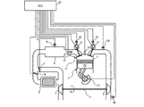
- FIG. 1 is a diagram illustrating a system configuration according to the first embodiment of the present invention.
- the system of this embodiment includes an internal combustion engine 1.
- the internal combustion engine 1 communicates with an intake passage (intake pipe) and an exhaust passage (exhaust pipe).
- the internal combustion engine 1 includes a turbocharger 4 that rotates a turbine 2 by energy contained in exhaust gas and supercharges intake air by a compressor 3.
- An intercooler 5 is provided downstream of the compressor 3, and a throttle valve 6 for controlling the amount of intake air flowing into the throttle cylinder 7 through the intake passage is assembled further downstream of the intercooler 5.
- the throttle valve 6 is an electronically controlled throttle valve that can control the valve opening degree independently of the accelerator pedal depression amount.
- An intake manifold 8 communicates with the downstream side of the throttle valve 6.
- a temperature and pressure sensor 9 is assembled in the intake manifold 8.
- a flow enhancement valve 10 is disposed downstream of the intake manifold 8 to reinforce the turbulence in the cylinder 7 by causing a drift in the intake air.
- an in-cylinder direct injection type fuel injection valve 11 for directly injecting fuel into the cylinder 7 is disposed.
- the internal combustion engine 1 includes a variable valve mechanism that continuously varies a valve opening / closing phase and a lift in each of an intake valve 12 and an exhaust valve 13.
- sensors 14 and 15 for detecting the opening / closing phase of the valve and the lift are respectively assembled to the intake valve 12 and the exhaust valve 13.
- an ignition plug 16 is attached that exposes an electrode portion in the cylinder 7 and ignites a combustible air-fuel mixture by spark.
- a crank angle sensor 17 is assembled to the crankshaft. Based on the signal output from the crank angle sensor 17, the rotational speed of the internal combustion engine 1 can be detected.
- a temperature and pressure sensor 18 for detecting the exhaust gas temperature and pressure is assembled in the exhaust passage.
- the turbine 2 is disposed downstream of the temperature and pressure sensor 18 in the exhaust passage.
- An air-fuel ratio sensor 19 is assembled downstream of the turbine 2, and feedback control is performed based on the detection result of the air-fuel ratio sensor 19 so that the fuel injection amount supplied from the fuel injection valve 11 becomes the target air-fuel ratio. Is done.
- the system of the present embodiment includes an ECU (Electronic Control Unit) 20 that is a control device, as shown in FIG.
- the ECU 20 is connected to the above-described various sensors and various actuators. Actuators such as the throttle valve 6, the fuel injection valve 11, the intake / exhaust valves 12 and 13 with a variable mechanism are controlled by the ECU 20. Furthermore, based on the signals input from the various sensors described above, the operating state of the internal combustion engine 1 is detected, and the spark plug 16 ignites at a timing determined by the ECU 20 according to the operating state.
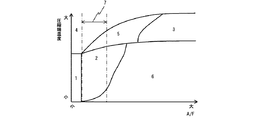
- FIG. 2 is a diagram for explaining an operable range based on the air-fuel ratio (hereinafter referred to as A / F) in the cylinder 7 and the compression end temperature of SI, HCCI, and homogeneous lean spark ignition combustion (hereinafter referred to as lean SI). is there.
- the compression end temperature refers to the in-cylinder temperature immediately before ignition during SI, and the in-cylinder temperature immediately prior to ignition of the air-fuel mixture during HCCI.
- Region 1 represents an SI region operated in the vicinity of the stoichiometric mixture ratio (hereinafter referred to as SI region), and region 2 represents a region where the air-fuel mixture is homogeneous and lean and stably burns as SI (hereinafter referred to as lean SI). Area).
- the vicinity of the stoichiometric mixture ratio includes a range in which NOx in the exhaust can be purified with a three-way catalyst.
- Region 3 represents a region where the spark ignition by the spark plug 16 is stopped and combustion is performed by self-ignition of the air-fuel mixture (hereinafter, HCCI region).
- Area 4 represents an SI area. This region 4 also represents a region where knocking occurs due to an increase in compression end temperature (hereinafter referred to as SI knocking region).
- Region 5 represents a region where knocking occurs due to an increase in compression end temperature (hereinafter referred to as HCCI knocking region) when operating with SI and HCCI.
- a region 6 represents a region where misfire occurs due to a decrease in compression end temperature and an increase in A / F (hereinafter, misfire region).
- Region 7 is a lean state in which the A / F of the air-fuel mixture is relatively close to the stoichiometric mixture ratio and discharges a large amount of NOx in the chemical reaction process from the high combustion temperature (hereinafter referred to as a NOx-rich generation region) It represents.
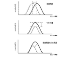
- FIG. 3 is a diagram for explaining the operation method of the variable valve mechanism of the phase variable type and the variable valve mechanism of the lift variable type.
- the variable valve mechanism of the phase variable type only the phase can be changed with the valve open period (hereinafter referred to as valve working angle) constant.
- valve working angle the valve open period
- the valve lift and the operating angle can be changed simultaneously.
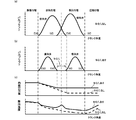
- FIG. 4 is a diagram for explaining the temperature rise effect of the variable valve mechanism using the variable valve mechanism of the phase variable type and the variable valve mechanism of the lift variable mechanism type.
- EVO, EVC, IVO, and IVC represent an exhaust valve opening timing, an exhaust valve closing timing, an intake valve opening timing, and an intake valve closing timing, respectively.
- the amount of negative overlap (hereinafter referred to as NO / L) in which the intake valve and the exhaust valve are closed at the same time increases due to changes in the phase and lift of the valve. Therefore, as shown in FIG. 4 (c), the amount of hot exhaust gas trapped in the cylinder 7 (hereinafter referred to as internal EGR gas amount) increases, so that the in-cylinder temperature at the intake valve closing timing increases. For this reason, the compression end temperature at the time of SI and HCCI increases in the presence of NO / L compared to the absence of NO / L.
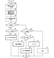
- FIG. 5 is a flowchart showing control of the HCCI from the SI by the ECU 20.
- step S01 A / F is detected from the air-fuel ratio sensor 19.
- step S02 the compression end temperature Tc is estimated from the temperature and pressure sensor 9 and the exhaust variable position sensor 15.
- the temperature and pressure sensor 9 detects the intake temperature and the intake pressure
- the exhaust variable position sensor 15 detects the closing timing of the exhaust valve 13
- the internal EGR gas amount is estimated.
- the in-cylinder temperature at the closing timing of the intake valve 12 detected from the intake variable position sensor 14 is estimated, and an estimated value Tc of the compression end temperature is calculated by a calculation assuming adiabatic compression.
- the intake step S03 the A / F and in-cylinder temperature Tc in steps S01 and S02 are read.
- step S04 it is determined whether the current combustion mode is a spark ignition combustion mode (hereinafter referred to as SI mode).
- SI mode spark ignition combustion mode
- the SI mode (Mode-1) It determines with it being an operation area
- the process proceeds to step S08.
- step S05 it is determined whether lean SI is possible based on the A / F and compression end temperature Tc read in step S03.
- the compression end temperature Tc is higher than the stable combustion limit temperature Tlimit of the lean SI and lower than the knocking limit temperature TLknock of the homogeneous SI (Tlimit ⁇ Tc ⁇ TLknock)
- Tlimit ⁇ Tc ⁇ TLknock the knocking limit temperature TLknock of the homogeneous SI
- step S08 it is determined whether the operation mode that does not satisfy the SI mode criterion is the lean SI region.
- the above criterion is determined to be the lean SI region when the compression end temperature Tc is lower than the HCCI establishment limit temperature THlimit (Tc ⁇ THlimit) while the A / F is maintained near the stable combustion limit of the lean SI. (S08: YES), the process proceeds to step S09. If the compression end temperature Tc is higher than the HCCI establishment limit temperature THlimit (Tc> THlimit) (S08: NO) when the A / F is maintained near the stable combustion limit of the lean SI, step S12 Then, the compression self-ignition combustion mode (Mode-6, hereinafter referred to as HCCI mode) shown in FIG. 6 is performed.
- Mode-6 hereinafter referred to as HCCI mode
- step S09 it is determined whether HCCI is possible based on the A / F read in step S03 and the in-cylinder temperature Tc.
- the compression end temperature Tc is near the knock limit temperature TLknock of homogeneous SI (Tc ⁇ TLknock)
- the above determination method determines that the operation can be performed with HCCI (S09: YES), and proceeds to step S10, as shown in FIG.
- Compressed self-ignition combustion switching control (Mode-5, hereinafter referred to as HCCI switching control) is performed.
- step S11 the homogeneous lean spark ignition combustion control mode (Mode-4, hereinafter, lean SI mode) as the “intermediate combustion mode” shown in FIG. 6 is performed.
- Mode-4 homogeneous lean spark ignition combustion control mode
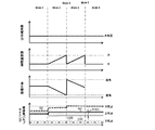
- FIG. 6 is a diagram for explaining a change in each control target value when switching from SI to HCCI.
- the horizontal axis represents time, the vertical axis represents intake pipe pressure, fuel injection amount, ignition timing, and intake / exhaust valve timing. Each control target value is shown.
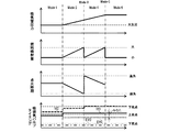
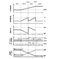
- FIG. 7 is a diagram for explaining changes in each state quantity at the time of switching from SI to HCCI.
- the horizontal axis represents time, the vertical axis represents intake air amount, A / F, compression end temperature, fuel injection amount, ignition timing, And each state quantity of torque is shown.
- the lean SI preparation control (Mode-2) in the first embodiment of FIG. 5 will be described.
- homogeneous SI preparation control (Mode-2) is performed as shown in FIG. 6 as a preparation stage.
- the intake valve opening timing (IVO) is retarded from the SI control value, and the exhaust valve closing timing (EVC) is advanced.
- IVO intake valve opening timing
- EGR exhaust valve closing timing
- the intake amount increases. Therefore, by increasing the fuel injection amount and retarding the ignition timing, as shown in FIG. 7, the A / F is maintained in the vicinity of the stoichiometry and the occurrence of torque fluctuation is suppressed.
- the lean SI switching control (Mode-3) in FIG. 5 will be described.
- switching control to lean SI shown in FIG. 6 is performed.
- torque undershoot accompanying a decrease in the fuel injection amount is prevented, and torque fluctuations are reduced. It becomes possible to switch to suppression and lean SI.
- the lean SI control (Mode-4) in FIG. 5 will be described.
- lean SI control is performed as shown in FIG. 6 as a preparation stage.
- the intake amount is increased by further increasing the operating angle of the intake valve from the control value of the lean SI switching control. Therefore, by increasing the fuel injection amount and retarding the ignition timing, as shown in FIG. 7, the A / F is maintained near the stability limit of the lean SI and the occurrence of torque fluctuation is suppressed.
- Fig. 5 shows the HCCI switching control (Mode-5) in Fig. 5.
- HCCI switching control shown in FIG. 6 is performed.
- the switching to HCCI is immediately performed while suppressing the torque fluctuation.
- FIG. 7 shows a series of state quantities when switching control from SI to HCCI is performed.
- lean SI preparation control Mode-2
- the intake amount increases and the fuel injection amount is increased to maintain the A / F in the vicinity of the stoichiometric mixture ratio, and the exhaust loss is increased by retarding the ignition timing.
- the torque fluctuation is suppressed by reducing the output.
- the lean SI switching control (Mode-3) reduces the fuel injection amount, and the A / F of the air-fuel mixture can be controlled to a target condition for each cycle. Therefore, the lean SI control (Mode-) 4). Therefore, the NOx emission amount can be reduced.
- by advancing the ignition timing as compared to before the A / F switching, torque undershoot accompanying a decrease in the fuel injection amount is prevented and torque fluctuation is suppressed.
- FIG. 8 shows A / F and compression end temperature when HCCI switching control is performed from SI.
- the black dots indicate the cycle passing points during the transition period.
- the compression end temperature and the A / F based on the information of the temperature and pressure sensor provided in the intake passage and the air-fuel ratio sensor attached to the exhaust passage.
- ECU 20 for estimating the intake / exhaust variable valve mechanism, fuel injection, and ignition timing in consideration of the estimated compression end temperature and A / F during the transition from SI to HCCI Therefore, a cycle in which a large amount of NOx is generated is suppressed, and NOx emission is reduced.
- the intake air amount is controlled by the operating angle of the intake valve
- the internal EGR amount is controlled by the closing timing of the exhaust valve
- the fuel injection amount is controlled based on the intake air amount estimated from the operating angle of the intake valve
- the target air-fuel ratio is corrected. Therefore, the A / F and the compression end temperature can be estimated only by the operation of the intake / exhaust valve. As a result, since the reading operation is reduced, switching control with high controllability can be realized.
- An ECU that estimates the compression end temperature and the A / F based on the information of the temperature and pressure sensor provided in the intake passage and the air-fuel ratio sensor attached to the exhaust passage is provided to switch from SI to HCCI.
- the operation of the control device for the internal combustion engine 1 according to the second embodiment of the present invention will be described with reference to FIGS. 1 to 5 and FIGS. 7 to 9.
- lean SI preparation control in the second embodiment will be described.
- lean SI preparation control (Mode-2) is performed as shown in FIG. 9 as a preparation stage.
- the intake valve opening timing (IVO) is retarded from the SI control value, and the exhaust valve closing timing (IVC) is advanced.
- IVO intake valve opening timing
- IVC exhaust valve closing timing
- the intake pressure and the intake density are increased. Due to the above action, the temperature of the air-fuel mixture increases, and as a result, the compression end temperature increases.
- the intake amount increases due to an increase in the working angle of the intake valve and an increase in the intake pressure. Therefore, by increasing the fuel injection amount and retarding the ignition timing, as shown in FIG. 7, the A / F is maintained in the vicinity of the stoichiometry, the exhaust loss is increased, and the output is reduced, thereby reducing the torque. Fluctuation is suppressed.
- the lean SI switching control (Mode-3) in FIG. 5 will be described.
- the switching control to the lean SI shown in FIG. 9 is performed.
- torque undershoot accompanying a decrease in the fuel injection amount is prevented, and torque fluctuations are reduced. It is possible to suppress and switch to lean SI.
- the lean SI control (Mode-4) in FIG. 5 will be described.
- lean SI control is performed as shown in FIG. 9 as a preparation stage.
- the actual compression ratio is increased and the compression end temperature is increased by further bringing the closing timing of the intake valve closer to the bottom dead center from the control value of the lean SI switching control.
- the intake pressure and the intake density are increased. Due to the above action, the temperature of the air-fuel mixture increases, and as a result, the compression end temperature increases.
- Increasing the intake valve operating angle and intake pressure increases the intake air amount, but also increases the fuel injection amount and retards the ignition timing, thereby reducing the A / F as shown in FIG. Torque fluctuations are suppressed by maintaining the vicinity of the SI stability limit, increasing exhaust loss, and reducing output.
- Fig. 5 shows the HCCI switching control (Mode-5) in Fig. 5.
- HCCI switching control shown in FIG. 9 is performed.
- switching to HCCI is performed immediately while suppressing the occurrence of torque fluctuation.
- the configuration and operation of the control device for an internal combustion engine according to the third embodiment of the present invention will be described with reference to FIGS. 2 to 5, 7, 8, 10, and 11. The different parts will be explained.
- the control device for the internal combustion engine of the third embodiment is switched from SI to HCCI, the operating condition of the internal combustion engine is higher than that of the second embodiment, that is, the intake pressure by the turbocharger 4 needs to be further increased.
- the purpose is to improve the response of the rise in the in-cylinder temperature.
- FIG. 10 is a diagram for explaining a system configuration according to the third embodiment of the present invention.
- the basic configuration is the same as the system configuration of the first and second embodiments described with reference to FIG.
- a part of the configuration downstream of the compressor 3 of the third embodiment is different from that of the first and second embodiments.
- the downstream of the compressor 3 is branched into two flow paths, and an intercooler 5 is provided in the first flow path.
- a first throttle valve 6 is assembled as a “bypass valve” for controlling the amount of intake air flowing into the throttle cylinder 7 through the intake passage.
- a second throttle valve 7 for controlling the amount of intake air flowing into the throttle cylinder 7 through the intake passage is assembled in the second passage.
- Both throttle valves 6 and 7 are electronically controlled throttle valves that can control the valve opening independently of the amount of accelerator pedal depression.
- the intake air temperature can be controlled by changing the ratio between the opening degree of the first throttle valve 6 and the opening degree of the second throttle valve 7.
- the first flow path and the second flow path merge downstream of the throttle valves 6 and 7, and the intake manifold 8 communicates with the downstream thereof.
- lean SI preparation control in the third embodiment in FIG. 5 will be described.
- lean SI preparation control (Mode-2) is performed as shown in FIG. 11 as a preparation stage.
- the intake valve opening timing (IVO) is retarded from the SI control value, and the exhaust valve closing timing (EVC) is advanced.
- IVO intake valve opening timing
- EGR exhaust valve closing timing
- the internal EGR amount increases, and as a result of the rise in the in-cylinder temperature, the compression end temperature increases.
- the actual compression ratio is increased and the compression end temperature is increased by increasing the intake valve operating angle and bringing the intake valve closing timing closer to the bottom dead center.
- the operation of the turbocharger 4 increases the intake pressure and the intake density.
- the above action increases the temperature of the air-fuel mixture, resulting in an increase in the compression end temperature.
- the amount of air flowing into the intercooler 5 is reduced, and the temperature sucked into the internal combustion engine is increased, so that during the compression stroke The compression end temperature of increases.
- the intake amount increases due to an increase in the working angle of the intake valve and an increase in the intake pressure. Therefore, by increasing the fuel injection amount and retarding the ignition timing, as shown in FIG. 7, the A / F is maintained in the vicinity of the stoichiometry, the exhaust loss is increased, and the output is decreased, thereby reducing the torque. Fluctuation is suppressed.
- the lean SI switching control (Mode-3) in FIG. 5 will be described.
- lean SI switching control shown in FIG. 11 is performed.
- the ignition timing is advanced compared to before the A / F switching, so that the fuel Torque undershoot associated with a decrease in injection amount can be prevented, torque fluctuations can be suppressed, and switching to lean SI can be performed immediately.
- lean SI control (Mode-4) in FIG. 5 will be described.
- lean SI control is performed as shown in FIG. 11 as a preparation stage.
- the actual compression ratio is increased and the compression end temperature is increased by further bringing the intake valve close timing closer to the bottom dead center from the control value of the lean SI switching control. Further, by accelerating the operation of the turbocharger 4, the intake pressure and the intake density are increased.
- the above action increases the temperature of the air-fuel mixture, resulting in an increase in the compression end temperature.
- the amount of air flowing into the intercooler 5 is reduced, and the temperature taken into the internal combustion engine.
- the compression end temperature during the compression stroke increases.
- the intake amount is increased by increasing the working angle of the intake valve and the intake pressure. Therefore, by increasing the fuel injection amount and retarding the ignition timing, as shown in FIG. 7, the A / F is maintained near the stability limit of the lean SI, the exhaust loss is increased, and the output is reduced. Thus, torque fluctuation is suppressed.
- Fig. 5 shows the HCCI switching control (Mode-5) in Fig. 5.
- HCCI switching control shown in FIG. 11 is performed.
- switching to HCCI is performed immediately while suppressing the occurrence of torque fluctuation.
- the in-cylinder temperature is controlled by the NO / L period and the operating angle of the intake valve
- the intake air temperature is controlled by controlling the intercooler 5 and the throttle valve downstream of the bypass pipe, and supercharging.
- the intake air temperature can be controlled by controlling the intake pressure by the machine. Therefore, temperature control by the control unit optimum for the operating conditions is possible. As a result, it is possible to perform temperature control with high response at the time of an operation switching transition requiring responsiveness, and it is possible to realize control with high switching responsiveness.
Landscapes
- Engineering & Computer Science (AREA)
- General Engineering & Computer Science (AREA)
- Chemical & Material Sciences (AREA)
- Combustion & Propulsion (AREA)
- Mechanical Engineering (AREA)
- Signal Processing (AREA)
- Physics & Mathematics (AREA)
- Thermal Sciences (AREA)
- Theoretical Computer Science (AREA)
- Output Control And Ontrol Of Special Type Engine (AREA)
- Electrical Control Of Air Or Fuel Supplied To Internal-Combustion Engine (AREA)
- Combined Controls Of Internal Combustion Engines (AREA)
- Combustion Methods Of Internal-Combustion Engines (AREA)
- Electrical Control Of Ignition Timing (AREA)
Abstract
SIからSCCIへの切り替え時に、失火や不正燃焼によるトルク変動を適切に防止しつつ、切替時のNOxの排出を抑制する。 シリンダ7内の空燃比と圧縮端温度とが相互に異なる複数の燃焼モードを実施する内燃機関の制御装置であって、一方の燃焼モードから他方の燃焼モードに切り替える途中に、前記一方の燃焼モードの空燃比および前記他方の燃焼モードの空燃比とは異なる空燃比を維持しつつ、前記圧縮端温度を増加させる中間燃焼モードを実施するので、SIを行う運転モードと、HCCIを行う運転モードとの切り替え時において、シリンダ7内の温度と空燃比とが適切に制御されて、失火や不正燃焼によるトルク変動を適切に防止しつつ、NOxの排出を抑制することができる。
Description
本発明は、内燃機関の制御装置に係り、特に、火花点火燃焼と、圧縮自己着火燃焼との燃焼モードの切り替えに好適な内燃機関の制御装置に関する。
火花点火による予混合火炎伝播燃焼方式を採用した内燃機関は、熱効率の向上を目的として圧縮比を高め過ぎると、例えば、ノッキングやプレイグニションと呼ばれる異常燃焼を発生するため、高圧縮比化による熱効率の向上には限界がある。そこで、排ガス等の不活性ガスによって希釈された可燃混合気をピストンで圧縮させることで自己着火燃焼を行う予混合圧縮着火燃焼(HCCI:Homogeneous Charge Compression Ignition。以下、単にHCCI)方式を採用した内燃機関の開発が進められている。
HCCI方式の内燃機関は、従来の火花点火燃焼(SI:Spark Igition。以下、単にSI)方式の内燃機関と比較して、圧縮比を高く設定することができ、さらに希薄燃焼による燃焼温度低下により、冷却損失やNOxの低減を実現できる。しかしながら、HCCIでは、着火タイミングが圧縮行程における化学反応の過程に依存するため、シリンダ内の温度、不活性ガスによる希釈割合、燃料噴射タイミング等を緻密に制御する必要がある。
HCCI方式の内燃機関では、正常燃焼を実現できる運転可能範囲が、従来のSI方式の内燃機関よりも狭く、実用運転範囲の全体をカバーすることができない。そのため、SIモードと、HCCIモードとの切替えが必要となる。SIモードと、HCCIモードとでは、成立条件が大きく異なるため、燃焼モードの切り替え時に、制御値を単純に切り替えるだけでは、トルク変動が生じる課題があった。
このような課題を解決する手段として、特許文献1には、SIモードからHCCIモードに切り替える際に、中間状態として、均質状態と成層状態との2種類のSIモードを実施する内燃機関の制御装置が開示されている。この特許文献1の制御装置によれば、燃焼モードの切り替え時に、トルク変動を適切に防止することができる。
特許文献1の技術では、SIからHCCIへの切り替え時のトルク変動を抑制することが可能である。しかし、SIからHCCIに切り替える際に、連続的に空燃比(以下、A/F)をリーン化する制御をしている。従って、A/Fが量論混合比に近く且つそれよりも希薄な状態での燃焼を経由するため、燃焼温度が比較的高くなり、NOxを大量に発生する問題があった。また、成層リーン燃焼も合わせて経由するため、NOxが増加する課題がある。
本発明は、上記する問題に鑑みてなされたものであり、その目的とすることは、SIからHCCIへの切り替え時に、失火や不正燃焼によるトルク変動を適切に防止しつつ、切替時のNOxの排出を抑制できる内燃機関の制御装置を提供することにある。
上記課題を解決するため、本発明の制御装置は、シリンダ内の空燃比と圧縮端温度とが相互に異なる複数の燃焼モードを実施する内燃機関の制御装置であって、一方の燃焼モードから他方の燃焼モードに切り替える途中に、前記一方の燃焼モードの空燃比および前記他方の燃焼モードの空燃比とは異なる空燃比を維持しつつ、前記圧縮端温度を増加させる中間燃焼モードを実施する。
本発明によれば、SIを行う運転モードと、HCCIを行う運転モードとの切り替え時において、シリンダ内の温度と空燃比とが適切に制御されるので、失火や不正燃焼によるトルク変動を適切に防止しつつ、NOxの排出を抑制することができる。
以下、図1~図8を用いて、本発明の実施例1による内燃機関1の制御装置(ECU20)の構成及び動作について説明する。実施例1は、非過給条件で圧縮着火燃焼(以下、HCCI)が成立する条件で、火花点火燃焼(以下、SI)からHCCIに切り替える内燃機関1のECU20の構成、及び動作について言及する。
図1は、本発明の実施例1に係るシステム構成を説明する図である。本実施例のシステムは、内燃機関1を備えている。内燃機関1には、吸気流路(吸気管)と排気流路(排気管)とが連通されている。内燃機関1には、排気に含まれるエネルギによってタービン2を回転し、コンプレッサ3によって吸入空気を過給するターボ過給機4が備えられている。コンプレッサ3の下流には、インタークーラ5が備えられており、その更に下流には、吸気流路を絞りシリンダ7に流入する吸入空気量を制御するためのスロットル弁6が組付けられている。スロットル弁6は、アクセルペダル踏量とは独立して弁開度を制御することができる電子制御式スロットル弁である。スロットル弁6の下流には、吸気マニホールド8が連通している。吸気マニホールド8には、温度及び圧力センサ9が組み付けられている。吸気マニホールド8の下流には、吸気に偏流を生じさせることによって、シリンダ7内の流れの乱れを強化する流動強化弁10が配置されている。
シリンダ7内には、燃料をシリンダ7内に直接噴射するシリンダ内直接噴射式燃料噴射弁11が配置されている。内燃機関1は、バルブ開閉の位相とリフトとを連続的に可変とする可変バルブ機構を、吸気バルブ12と排気バルブ13とにそれぞれ備えている。可変バルブ機構には、バルブの開閉位相とリフトとをそれぞれ検知するためのセンサ14,15が、吸気バルブ12と排気バルブ13とにそれぞれ組付けられている。
シリンダヘッド部には、シリンダ7内に電極部を露出させ、スパークによって可燃混合気を引火する点火プラグ16が組付けられている。クランク軸には、クランク角度センサ17が組付けられている。クランク角度センサ17から出力される信号に基づき、内燃機関1の回転速度を検出することができる。
排気流路には、排ガス温度と圧力とを検知するための温度及び圧力センサ18が組み付けられている。排気流路における温度及び圧力センサ18の下流には、タービン2が配置されている。タービン2の下流には、空燃比センサ19が組付けられており、空燃比センサ19の検出結果に基づき、燃料噴射弁11から供給される燃料噴射量が目標空燃比となるように、フィードバック制御が行われる。
本実施形態のシステムは、図1に示すように、制御装置であるECU(Electronic Control Unit)20を備えている。ECU20には、上述した各種センサと各種アクチュエータとが接続されている。スロットル弁6、燃料噴射弁11、可変機構付き吸排気バルブ12及び13等のアクチュエータは、ECU20により制御されている。さらに、上述した各種センサより入力された信号に基づき、内燃機関1の運転状態を検知し、運転状態に応じてECU20によって決定されたタイミングで、点火プラグ16が点火を行う。
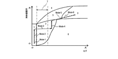
図2は、SI、HCCI及び均質リーン火花点火燃焼(以下、リーンSI)の、シリンダ7内の空燃比(以下、A/F)と圧縮端温度とに基づいた運転可能領域を説明する図である。以下では、圧縮端温度とは、SI時は点火直前の筒内温度を指し、HCCI時は混合気の着火直前の筒内温度を指す。領域1は、量論混合比近傍で運転されるSI領域(以下、SI領域)を表し、領域2は、混合気が均質と希薄とで、SIとして安定的に燃焼する領域(以下、リーンSI領域)を表す。なお、量論混合比近傍とは、排気中のNOxを三元触媒で浄化可能な範囲を含む。
領域3は、上記点火プラグ16による火花点火を停止し、混合気の自着火によって燃焼する領域(以下、HCCI領域)を表している。領域4は、SIの領域を表している。この領域4は、圧縮端温度の増加によってノッキングが発生する領域(以下、SIノッキング領域)をも表している。
領域5は、SIとHCCIとで運転した場合、圧縮端温度の増大からノッキングが発生する領域(以下、HCCIノッキング領域)を表している。領域6は、圧縮端温度の低下とA/Fの増大とによって、失火が発生する領域(以下、失火領域)を表している。領域7は、混合気のA/Fが比較的量論混合比近傍の希薄状態にあり、燃焼温度の高さから化学反応過程でNOxを多量に排出する領域(以下、NOx多量発生領域)を表わしている。
領域1のSIから領域3のHCCI領域へ切り替える際、A/Fが大きく異なるために、適切な切り替え制御部が必要であるが、各種アクチュエータの応答性から即座に領域1から領域3に切り替えることは困難である。そのため領域1のSI領域から領域3のHCCI領域へ切り替える際に、領域4~7を通過せずに、適切な制御部をもって、切り替えを実施する必要がある。
図3は、位相可変型の可変バルブ機構とリフト可変型の可変バルブ機構との動作方法を説明する図である。位相可変型の可変バルブ機構では、バルブの開いている期間(以下、バルブ作用角)を一定として、位相のみ変化することができる。リフト可変型の可変バルブ機構では、バルブリフトと作動角とを同時に変化することができる。位相可変バルブ機構とリフト可変バルブ機構との両方を用いることによって、バルブ開き時期またはバルブ閉じ時期のいずれかを固定した状態で、位相とリフトとを同時に可変化することができる。
図4は、位相可変型の可変バルブ機構とリフト可変機構型の可変バルブ機構とを用いた、可変バルブ機構による温度上昇効果を説明する図である。図4に示す、EVO、EVC、IVO、IVCはそれぞれ、排気バルブ開時期、排気バルブ閉時期、吸気バルブ開時期、吸気バルブ閉時期を表す。位相可変型の可変バルブ機構とリフト可変機構型の可変バルブ機構とを用いて、位相とリフトとを同時に操作することで、図4(a)のバルブ開閉プロフィールから、吸気バルブと排気バルブとの位相及びリフトを図4(b)のように変化させることができる。
図4(b)では、バルブの位相及びリフトの変化により、吸気バルブと排気バルブとが同時に閉じているネガティブオーバーラップ(以下、N‐O/L)量が増加している。そのため、図4(c)に示すように、シリンダ7内にトラップされる高温の排気ガス量(以下、内部EGRガス量)が増大することで、吸気弁閉じ時期の筒内温度が増大する。このため、N-O/Lがある場合の方が、N-O/Lが無い場合より、SI及びHCCI時の圧縮端温度が増加する。
図5は、ECU20によるSIからHCCIの制御を示すフローチャートである。
ステップS01では、空燃比センサ19からA/Fを検出する。ステップS02では、温度及び圧力センサ9と、排気可変ポジションセンサ15とから圧縮端温度Tcを推定する。
上記推定方法は、温度及び圧力センサ9によって、吸気温度及び吸気圧力を検出し、排気可変ポジションセンサ15によって、排気バルブ13の閉じ時期を検出し、内部EGRガス量を推定する。上記検出及び推定により、吸気可変ポジションセンサ14から検出される吸気バルブ12の閉時期における、筒内温度を推定し、断熱圧縮を仮定した計算で圧縮端温度の推定値Tcを算出する。吸気ステップS03では、ステップS01とステップS02とのA/F及び筒内温度Tcを読み込む。ステップS04では、現在の燃焼モードが火花点火燃焼モード(以下、SIモード)か判定する。
上記判定方法は、A/Fが量論混合比近傍に維持された状態で、圧縮端温度TcがSIのノッキング限界温度TSknockより低い場合(Tc<TSknock)、SIモード(Mode-1)での運転領域であると判定し(S04:YES)、ステップS05に進む。SIのノッキング限界温度TSknockより高い場合(Tc>TSknock)(S04:NO)、ステップS08に進む。
ステップS05では、ステップS03で読み込まれたA/F及び圧縮端温度TcでリーンSIが可能か判定する。上記判定方法は、圧縮端温度TcがリーンSIの安定燃焼限界温度Tlimitより高く、かつ、均質SIのノッキング限界温度TLknockより低い場合(Tlimit<Tc<TLknock)、リーンSIで運転可能であると判断し(S05:YES)、ステップS06に進む。ステップS06では、図6に示す均質リーン火花点火燃焼切り替え制御(Mode-3。以下、リーンSI切り替え制御)を実施する。上記条件を満たさない場合(S05:NO)は、ステップS07に進み、図6に示す均質リーン火花点火燃焼準備制御(Mode-2。以下、均質SI準備制御)を実施する。
ステップS08では、SIモードの判定基準を満たさなかった運転モードが、リーンSI領域か判定する。
上記判定基準は、A/FがリーンSIの安定燃焼限界近傍に維持された状態で、圧縮端温度TcがHCCIの成立限界温度THlimitより低い場合(Tc<THlimit)、リーンSI領域であると判定し(S08:YES)、ステップS09に進む。上記判定基準は、A/FがリーンSIの安定燃焼限界近傍に維持された状態で、圧縮端温度TcがHCCIの成立限界温度THlimitより高い場合(Tc>THlimit)(S08:NO)、ステップS12に進み、図6に示す圧縮自己着火燃焼モード(Mode-6。以下、HCCIモード)を実施する。
ステップS09では、ステップS03で読み込まれたA/F及び筒内温度TcでHCCIが可能か判定する。上記判定方法は、圧縮端温度Tcが均質SIのノッキング限界温度TLknock近傍の場合(Tc≒TLknock)、HCCIで運転可能であると判断し(S09:YES)、ステップS10に進み、図6に示す圧縮自己着火燃焼切り替え制御(Mode-5。以下、HCCI切り替え制御)を実施する。上記条件を満たさない場合は(S08:NO)、ステップS11に進み、図6に示す「中間燃焼モード」としての均質リーン火花点火燃焼制御モード(Mode-4。以下、リーンSIモード)を実施する。
図6は、SIからHCCIへの切り替え時の各制御目標値の変化を説明する図であり、横軸に時間、縦軸に吸気管圧力、燃料噴射量、点火時期、及び吸排気バルブタイミングの各制御目標値を示す。図7は、SIからHCCIへの切り替え時の各状態量の変化を説明する図であり、横軸に時間、縦軸に吸気量、A/F、圧縮端温度、燃料噴射量、点火時期、及びトルクの各状態量を示す。
図5の実施例1におけるリーンSI準備制御(Mode-2)を説明する。SIモード(Mode-1)からリーンSIモード(Mode-4)に移行する際に、準備段階として図6に示すように均質SI準備制御(Mode-2)を実施する。SIの制御値から、吸気バルブの開時期(IVO)を遅角し、排気バルブの閉時期(EVC)を進角する。上記のバルブ操作を行い、N-O/L量を増大することで、内部EGR量が増え、筒内温度上昇の結果、圧縮端温度が増加する。吸気バルブの作用角を増加しつつ、吸気バルブの閉時期を下死点近傍に近づけることによって、実圧縮比を増大し、圧縮端温度を増大する。吸気バルブの作用角を増加させることによって、吸気量が増大する。そのため、燃料噴射量も増大させて、点火時期を遅角することによって、図7に示す通り、A/Fをストイキ近傍に維持するとともに、トルク変動が発生することを抑制する。
図5のリーンSI切り替え制御(Mode-3)を説明する。SIからリーンSIに移行する際に、リーンSIで運転可能であると判断すると、図6に示すリーンSIへの切り替え制御を実施する。均質SI準備制御の制御値から、燃料噴射量を減少させ、点火時期をA/F切り替え前に比べて進角することで、燃料噴射量の低下に伴うトルクのアンダーシュートを防ぎ、トルク変動を抑制、リーンSIへ切り替えが可能となる。
図5のリーンSI制御(Mode-4)を説明する。リーンSIからHCCIに移行する際に、準備段階として図6に示すようにリーンSI制御を実施する。リーンSI切り替え制御の制御値から、さらに吸気バルブの作用角を増大することによって、吸気量を増大する。そのため、燃料噴射量も増大させて、点火時期を遅角することによって、図7に示す通り、A/FをリーンSIの安定限界近傍に維持するとともに、トルク変動が発生することを抑制する。
図5のHCCIへの切り替え制御(Mode-5)を示す。リーンSI制御からHCCIに移行する際に、HCCIで運転可能であると判断すると、図6に示すHCCI切り替え制御を実施する。リーンSI制御の制御値から、燃料噴射量を減少させ、点火プラグによる点火を停止することで、トルク変動が発生することを抑制しつつ、即座にHCCI(Mode-6)へ切り替えを実施する。
図7は、SIからHCCIへの切り替え制御を実施した際の一連の状態量を示している。リーンSI準備制御(Mode-2)では、吸気量が増大すると共に、燃料噴射量を増大することによってA/Fを量論混合比近傍に保持し、点火時期の遅角により、排気損失を増加させ、出力を低下させることによって、トルク変動を抑制している。リーンSI切り替え制御(Mode-3)で燃料噴射量を減少し、混合気のA/Fをサイクルごとに狙った条件に制御できるため、NOx多量発生領域を通過せず、リーンSI制御(Mode-4)に切り替えることができる。そのため、NOx排出量を低減できる。さらに、点火時期をA/F切り替え前に比べて進角することによって、燃料噴射量の低下に伴うトルクのアンダーシュートを防ぎ、トルク変動を抑制する。
リーンSI制御(Mode-4)では、吸気量が増大すると共に、燃料噴射量を増大することによってA/FをリーンSI安定燃焼限界近傍に保持し、点火時期の遅角により、排気損失を増加させ、出力を低下させることによって、トルク変動を抑制している。HCCIへの切り替え制御(Mode-5)では、燃料噴射量を減少することで、混合気のA/Fを急激にリーン化するとともに、点火プラグによる点火を停止することで、NOx多量発生領域を通過せず、即座にHCCI(Mode-6)へ切り替えが可能となる。
図8は、SIからHCCI切り替え制御を実施した場合の、A/Fと圧縮端温度を示している。黒い点は過渡期間のサイクル通過点を示している。
SIモード(Mode-1)からリーンSI準備制御(Mode-2)に移行する際は、A/Fを量論混合比近傍に維持しながら、圧縮端温度を増加させる。リーンSI準備制御(Mode-2)からリーンSI切り替え制御(Mode-3)に移行する際は、A/Fを即座にリーン化しながら圧縮端温度を維持する。リーンSI切り替え制御(Mode-3)からリーンSIモード(Mode-4)に移行する際は、燃料噴射量を減少させる。リーンSIモード(Mode-4)からHCCI切り替え制御(Mode-5)に移行する際は、A/FをリーンSIの安定限界近傍に維持しながら、圧縮端温度を増加させる。HCCI切り替え制御(Mode-5)からHCCI(Mode-6)へ移行する際は、A/Fを即座にリーン化しながら圧縮端温度を維持する。
以上説明した通り、本実施例によれば、吸気流路に備えられた温度及び圧力センサと、排気流路に取り付けられた空燃比センサとの情報に基づいて、圧縮端温度と、A/Fとを推定するECU20を備え、SIからHCCIに切り替える過渡時において、推定された圧縮端温度と、A/Fとを考慮して、吸排気可変バルブ機構、燃料噴射、及び点火時期が適切に制御されるので、NOxが多量に発生するサイクルが抑制され、NOxの排出が減る。
吸気バルブの作用角によって吸気量を制御し、排気バルブの閉時期によって内部EGR量を制御し、吸気バルブの作用角から推定される吸気量に基づき燃料噴射量を制御し、目標空燃比に補正するので、吸排気バルブの動作のみによって、A/F及び圧縮端温度が推定できる。その結果、読み込み動作が軽減されるため、制御性が高い切り替え制御を実現できる。
吸気流路に備えられた温度及び圧力センサ、及び排気流路に取り付けられた空燃比センサの情報に基づいて、圧縮端温度と、A/Fとを推定するECUを備え、SIからHCCIに切り替える過渡時において、推定された圧縮端温度と、A/Fとに基づいて、運転モードを判断することによって、運転モードに則した可変バルブ機構、燃料噴射、及び点火時期の適切な制御が可能となり、制御性が高い切り替え制御を実現できる。
以下、図7~図11を用いて、実施例1以外のSIからHCCIの切り替え部を用いた、内燃機関1のECU20の構成及び動作の実施形態を説明する。実施例1で説明した図2~5のシステム構成及び制御装置の動作については同様であるため、省略する。
実施例2では、図1~5、図7~図9を用いて、本発明の実施例2による内燃機関1の制御装置の動作について、実施例1と異なる部分を説明する。実施例2は、SIからHCCIに切り替える際に、内燃機関1の運転条件が高負荷運転領域、つまりターボ過給機による吸気圧の上昇が必要な場合の、内燃機関1のECU20の構成、及び動作について言及する。
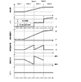
実施例2におけるリーンSI準備制御(Mode-2)を説明する。SI(Mode-1)からリーンSIモード(Mode-4)に移行する際に、準備段階として図9に示すようにリーンSI準備制御(Mode-2)を実施する。SIの制御値から、吸気バルブの開時期(IVO)を遅角し、排気バルブの閉じ時期(IVC)を進角する。上記のバルブ操作を行い、N-O/L量を増大することによって、内部EGR量が増え、筒内温度上昇の結果、圧縮端温度が増加する。吸気バルブの作用角をさらに増加しつつ、吸気バルブの閉時期を下死点近傍に近づけることによって、実圧縮比を増大し、圧縮端温度を増大する。ターボ過給機4の動作をさらに加速することによって、吸気圧力及び吸気密度が増大する。上記作用により、混合気の温度が増大する結果、圧縮端温度が増大する。吸気バルブの作用角の増加及び吸気圧力の増加により、吸気量が増大する。そのため、燃料噴射量も増大させて、点火時期を遅角することで、図7に示す通り、A/Fをストイキ近傍に維持するとともに、排気損失を増加させ、出力を低下させることによって、トルク変動を抑制している。
図5のリーンSI切り替え制御(Mode-3)を説明する。SIからリーンSIに移行する際に、リーンSIで運転可能であると判断すると、図9に示すリーンSIへの切り替え制御を実施する。均質SI準備制御の制御値から、燃料噴射量を減少させ、点火時期をA/F切り替え前に比べて進角することで、燃料噴射量の低下に伴うトルクのアンダーシュートを防ぎ、トルク変動を抑制し、リーンSIへ切り替えが可能となる。
図5のリーンSI制御(Mode-4)を説明する。リーンSIからHCCIに移行する際に、準備段階として図9に示すようにリーンSI制御を実施する。リーンSI切り替え制御の制御値から、さらに吸気バルブの閉時期を下死点近傍に近づけることで、実圧縮比を増大し、圧縮端温度を増大する。また、さらにターボ過給機4の動作を加速することで、吸気圧力及び吸気密度が増大する。上記作用により、混合気の温度が増大する結果、圧縮端温度が増大する。吸気バルブの作用角と吸気圧力とを増大することで、吸気量を増大するが、燃料噴射量も増大させて、点火時期を遅角することで、図7に示す通り、A/FをリーンSIの安定限界近傍に維持するとともに、排気損失を増加させ、出力を低下させることによって、トルク変動を抑制している。
図5のHCCI切り替え制御(Mode-5)を示す。リーンSI制御からHCCIに移行する際に、HCCIで運転可能であると判断すると、図9に示すHCCI切り替え制御を実施する。リーンSI制御の制御値から燃料噴射量を減少させ、点火プラグによる点火を停止することで、トルク変動が発生することを抑制しつつ、即座にHCCI(Mode-6)へ切り替えを実施する。
実施例3では、図2~5、図7、図8、図10、図11を用いて、本発明の実施例3による内燃機関の制御装置の構成、及び動作について、実施例1,2と異なる部分を説明する。実施例3の内燃機関の制御装置は、SIからHCCIに切り替える際に、実施例2より更に内燃機関の運転条件が高負荷運転領域、つまりターボ過給機4による吸気圧の更なる上昇が必要な場合、若しくは筒内温度の上昇の応答性向上を目的としている。
図10は、本発明の実施例3のシステム構成を説明する図である。基本的な構成は、図1で説明した本発明の実施例1、2のシステム構成と同じである。実施例3のコンプレッサ3よりも下流側の一部の構成が実施例1,2とは異なる。コンプレッサ3の下流は、2つの流路に分岐しており、第一の流路には、インタークーラ5が備えられている。インタークーラ5の下流には、吸気流路を絞りシリンダ7に流入する吸入空気量を制御するための「バイパスバルブ」としての第一のスロットル弁6が組付けられている。第二の流路には、吸気流路を絞りシリンダ7に流入する吸入空気量を制御するための第二のスロットル弁7が組付けられている。両スロットル弁6,7は、アクセルペダル踏量とは独立して弁開度を制御することができる電子制御式スロットル弁である。第一のスロットル弁6の開度と、第二のスロットル弁7の開度との比率を変化させることによって、吸気温度を制御することができる。第一の流路と、第二の流路とは、両スロットル弁6,7の下流で合流しており,その下流には吸気マニホールド8が連通している。
図5の実施例3におけるリーンSI準備制御(Mode-2)を説明する。SI(Mode-1)からリーンSIモード(Mode-4)に移行する際に、準備段階として図11に示すようにリーンSI準備制御(Mode-2)を実施する。SIの制御値から、吸気バルブの開時期(IVO)を遅角し、排気バルブの閉じ時期(EVC)を進角する。上記のバルブ操作を行い、N-O/L量を増大することで、内部EGR量が増え、筒内温度上昇の結果、圧縮端温度が増加する。さらに、吸気バルブの作用角を増加しつつ、吸気バルブの閉時期を下死点近傍に近づけることによって、実圧縮比を増大し、圧縮端温度を増大する。さらに、ターボ過給機4の動作をすることによって、吸気圧力及び吸気密度が増大する。
上記作用により、混合気の温度が増大する結果、圧縮端温度が増大する。第1,第2のスロットル弁開度を徐々に半開に近づけていくことによって、インタークーラ5内に流入する空気量を減少し、内燃機関に吸入される温度を増加させることによって、圧縮行程時の圧縮端温度が増加する。吸気バルブの作用角の増加及び吸気圧力の増加により、吸気量が増大する。そのため、燃料噴射量も増大させて、点火時期を遅角することによって、図7に示す通り、A/Fをストイキ近傍に維持するとともに、排気損失を増加させ、出力を低下させることによって、トルク変動を抑制している。
図5のリーンSI切り替え制御(Mode-3)を説明する。SIからリーンSIに移行する際に、リーンSIで運転可能であると判断すると、図11に示すリーンSI切り替え制御を実施する。リーンSI準備制御の制御値から、燃料噴射量を減少させ、点火時期を進角することで、図7に示すように、点火時期をA/F切り替え前に比べて進角することによって、燃料噴射量の低下に伴うトルクのアンダーシュートを防ぎ、トルク変動を抑制し、即座にリーンSIへ切り替えが可能となる。
図5のリーンSI制御(Mode-4)を説明する。リーンSIからHCCIに移行する際に、準備段階として図11に示すようにリーンSI制御を実施する。リーンSI切り替え制御の制御値から、さらに吸気バルブの閉時期を下死点近傍に近づけることによって、実圧縮比を増大し、圧縮端温度を増大する。さらに、ターボ過給機4の動作を加速することによって、吸気圧力及び吸気密度が増大する。
上記作用により、混合気の温度が増大する結果、圧縮端温度が増大する。第1スロットル弁開度を徐々に全閉、第2のスロットル弁開度を徐々に全開に近づけていくことによって、インタークーラ5内に流入する空気量を減少し、内燃機関に吸入される温度を増加させることによって、圧縮行程時の圧縮端温度が増加する。吸気バルブの作用角と吸気圧力とを増大することによって、吸気量を増大する。そのため、燃料噴射量も増大させて、点火時期を遅角することによって、図7に示す通り、A/FをリーンSIの安定限界近傍に維持するとともに、排気損失を増加させ、出力を低下させることにより、トルク変動を抑制している。
図5のHCCI切り替え制御(Mode-5)を示す。リーンSI制御からHCCIに移行する際に、HCCIで運転可能であると判断すると、図11に示すHCCI切り替え制御を実施する。リーンSI制御の制御値から燃料噴射量を減少させ、点火プラグによる点火を停止することで、トルク変動が発生することを抑制しつつ、即座にHCCI(Mode-6)へ切り替えを実施する。
本実施例によれば、N-O/L期間及び吸気バルブの作用角によって筒内温度を制御し、インタークーラ5及びバイパス管の下流のスロットル弁の制御によって、吸気温度を制御し、過給機による吸気圧力の制御によって、吸気温度を制御できる。従って、運転条件に最適な制御部による温度制御が可能である。その結果、応答性が求められる運転切り替え過渡時において、高応答な温度制御が可能となり、切り替え応答性が高い制御を実現できる。
1…内燃機関、5…インタークーラ、7…シリンダ、12…吸気バルブ、13…排気バルブ
Claims (7)
- シリンダ内の空燃比と圧縮端温度とが相互に異なる複数の燃焼モードを実施する内燃機関の制御装置であって、
一方の燃焼モードから他方の燃焼モードに切り替える途中に、前記一方の燃焼モードの空燃比および前記他方の燃焼モードの空燃比とは異なる空燃比を維持しつつ、前記圧縮端温度を増加させる中間燃焼モードを実施する、内燃機関の制御装置。 - 前記中間燃焼モードでは、前記シリンダ内の空気量と前記圧縮端温度とを増加させながら、前記空燃比を維持する、請求項1に記載の内燃機関の制御装置。
- 前記シリンダ内への吸気圧を増大させる制御と、吸気バルブの作用角を増大させる制御とのうちの少なくとも何れか一つによって、前記シリンダ内の空気量を増大させる、請求項2に記載の内燃機関の制御装置。
- 前記シリンダ内の前記空気量と燃料噴射量とを増大させながら、点火時期を遅角化する制御によって、前記空燃比を維持する、請求項2又は3に記載の内燃機関の制御装置。
- 前記一方の燃焼モードでは、前記空燃比を量論混合比近傍に維持する、請求項1乃至4の何れか一項に記載の内燃機関の制御装置。
- 前記一方の燃焼モードは、火花点火燃焼モードであり、前記中間燃焼モードは、均質リーン火花点火燃焼モードであり、前記他方の燃焼モードは、圧縮自己着火燃焼モードである、請求項1乃至4の何れか一項に記載の内燃機関の制御装置。
- 吸気バルブの閉時期をピストン下死点近傍に近付ける制御と、前記吸気バルブの開時期を排気バルブの閉時期よりも遅らせるマイナスオーバーラップ制御と、インタークーラのバイパスバルブを閉じる制御とのうちの少なくとも何れか一つによって、前記圧縮端温度を増加させる、請求項1乃至6の何れか一項に記載の内燃機関の制御装置。
Priority Applications (2)
| Application Number | Priority Date | Filing Date | Title |
|---|---|---|---|
| US16/341,251 US10941726B2 (en) | 2016-11-24 | 2017-11-01 | Control device for internal combustion engine |
| CN201780067056.0A CN109964019B (zh) | 2016-11-24 | 2017-11-01 | 内燃机的控制装置 |
Applications Claiming Priority (2)
| Application Number | Priority Date | Filing Date | Title |
|---|---|---|---|
| JP2016-227939 | 2016-11-24 | ||
| JP2016227939A JP6738716B2 (ja) | 2016-11-24 | 2016-11-24 | 内燃機関の制御装置 |
Publications (1)
| Publication Number | Publication Date |
|---|---|
| WO2018096884A1 true WO2018096884A1 (ja) | 2018-05-31 |
Family
ID=62195472
Family Applications (1)
| Application Number | Title | Priority Date | Filing Date |
|---|---|---|---|
| PCT/JP2017/039484 Ceased WO2018096884A1 (ja) | 2016-11-24 | 2017-11-01 | 内燃機関の制御装置 |
Country Status (4)
| Country | Link |
|---|---|
| US (1) | US10941726B2 (ja) |
| JP (1) | JP6738716B2 (ja) |
| CN (1) | CN109964019B (ja) |
| WO (1) | WO2018096884A1 (ja) |
Families Citing this family (2)
| Publication number | Priority date | Publication date | Assignee | Title |
|---|---|---|---|---|
| JP7415885B2 (ja) * | 2020-11-13 | 2024-01-17 | マツダ株式会社 | エンジンの制御方法、及び、エンジンシステム |
| JP7754040B2 (ja) * | 2022-09-30 | 2025-10-15 | トヨタ自動車株式会社 | 内燃機関の点火時期制御装置 |
Citations (1)
| Publication number | Priority date | Publication date | Assignee | Title |
|---|---|---|---|---|
| JP2012172665A (ja) * | 2011-02-24 | 2012-09-10 | Mazda Motor Corp | 火花点火式ガソリンエンジンの制御装置 |
Family Cites Families (21)
| Publication number | Priority date | Publication date | Assignee | Title |
|---|---|---|---|---|
| JP2005048751A (ja) * | 2003-07-31 | 2005-02-24 | Nissan Motor Co Ltd | エンジンの制御装置 |
| JP2005048749A (ja) * | 2003-07-31 | 2005-02-24 | Nissan Motor Co Ltd | エンジンの制御装置 |
| JP2005048746A (ja) * | 2003-07-31 | 2005-02-24 | Nissan Motor Co Ltd | 内燃機関の燃焼制御装置 |
| US7275514B2 (en) * | 2005-04-28 | 2007-10-02 | Gm Global Technology Operations, Inc. | Method of HCCI and SI combustion control for a direct injection internal combustion engine |
| JP2007016685A (ja) | 2005-07-07 | 2007-01-25 | Nissan Motor Co Ltd | 内燃機関の制御装置 |
| CN100363597C (zh) * | 2006-01-19 | 2008-01-23 | 清华大学 | 一种实现汽油机配气相位快速切换的装置及其方法 |
| JP2007247479A (ja) * | 2006-03-15 | 2007-09-27 | Hitachi Ltd | 圧縮着火式内燃機関の制御装置 |
| CN101016868B (zh) * | 2006-04-03 | 2013-05-15 | 天津大学 | 基于全可变气门机构节能超低排放双模式均质压燃发动机 |
| US7748355B2 (en) * | 2006-09-15 | 2010-07-06 | Ford Global Technologies, Llc | Approach for facilitating engine mode transitions |
| JP4687633B2 (ja) * | 2006-11-14 | 2011-05-25 | 株式会社豊田自動織機 | 予混合圧縮着火機関 |
| JP4821588B2 (ja) * | 2006-11-30 | 2011-11-24 | 株式会社豊田自動織機 | 予混合圧縮着火機関 |
| JP2008291720A (ja) * | 2007-05-23 | 2008-12-04 | Honda Motor Co Ltd | 内燃機関の制御装置 |
| US7481185B1 (en) * | 2007-08-14 | 2009-01-27 | Robert Bosch Gmbh | Multi-mode 2-stroke/4-stroke internal combustion engine |
| JP4642095B2 (ja) * | 2008-06-13 | 2011-03-02 | 日立オートモティブシステムズ株式会社 | エンジンの制御装置及び制御方法 |
| DE102010000741A1 (de) * | 2010-01-08 | 2011-07-14 | Robert Bosch GmbH, 70469 | Verfahren zum Umschalten zwischen einer HCCI-Verbrennung und einer SI-Verbrennung in einem Reaktor einer Brennkraftmaschine |
| US8616182B2 (en) * | 2010-05-24 | 2013-12-31 | GM Global Technology Operations LLC | Method and apparatus for controlling an internal combustion engine coupled to a passive selective catalytic reduction aftertreatment system |
| US9222432B2 (en) * | 2011-11-22 | 2015-12-29 | Robert Bosch Gmbh | Path planning during combustion mode switch |
| US9002623B2 (en) * | 2012-08-02 | 2015-04-07 | GM Global Technology Operations LLC | Fully flexible exhaust valve actuator control systems and methods |
| CN105518278B (zh) * | 2013-02-21 | 2019-02-12 | 罗伯特·博世有限公司 | 用于控制在si和hcci燃烧模式之间的转换的系统和方法 |
| JP5870951B2 (ja) * | 2013-03-25 | 2016-03-01 | マツダ株式会社 | 火花点火式エンジンの制御装置 |
| JP6320882B2 (ja) * | 2014-09-11 | 2018-05-09 | 日立オートモティブシステムズ株式会社 | 内燃機関の可変燃焼システム |
-
2016
- 2016-11-24 JP JP2016227939A patent/JP6738716B2/ja not_active Expired - Fee Related
-
2017
- 2017-11-01 US US16/341,251 patent/US10941726B2/en not_active Expired - Fee Related
- 2017-11-01 CN CN201780067056.0A patent/CN109964019B/zh not_active Expired - Fee Related
- 2017-11-01 WO PCT/JP2017/039484 patent/WO2018096884A1/ja not_active Ceased
Patent Citations (1)
| Publication number | Priority date | Publication date | Assignee | Title |
|---|---|---|---|---|
| JP2012172665A (ja) * | 2011-02-24 | 2012-09-10 | Mazda Motor Corp | 火花点火式ガソリンエンジンの制御装置 |
Also Published As
| Publication number | Publication date |
|---|---|
| US10941726B2 (en) | 2021-03-09 |
| US20190316540A1 (en) | 2019-10-17 |
| JP6738716B2 (ja) | 2020-08-12 |
| JP2018084201A (ja) | 2018-05-31 |
| CN109964019B (zh) | 2021-10-22 |
| CN109964019A (zh) | 2019-07-02 |
Similar Documents
| Publication | Publication Date | Title |
|---|---|---|
| CN101218423B (zh) | 在燃料直喷发动机受控自动点火与火花点火模式之间转换的方法 | |
| US7769525B2 (en) | Apparatus and method for controlling a homogeneous charge compression-ignited internal-combustion engine | |
| JP4326044B2 (ja) | 4サイクル内燃機関 | |
| US8050846B2 (en) | Apparatus and method for controlling engine | |
| CN102817736B (zh) | Hcci燃烧中的燃烧定相控制方法 | |
| WO2002014665A1 (en) | Compression ignition internal combustion engine | |
| JP4062870B2 (ja) | 内燃機関の燃焼制御装置 | |
| JP2012062865A (ja) | 内燃機関の制御装置及び制御方法 | |
| JP5040772B2 (ja) | エンジンの吸気弁制御方法及び吸気弁制御装置 | |
| US8381700B2 (en) | Systems and methods for exhaust gas recirculation control in homogeneous charge compression ignition engine systems | |
| JP4311604B2 (ja) | 自己着火エンジンの制御装置 | |
| JP6350304B2 (ja) | リーンバーンエンジン | |
| JP7088049B2 (ja) | 圧縮着火式エンジンの制御装置 | |
| JP6738716B2 (ja) | 内燃機関の制御装置 | |
| JP5310951B2 (ja) | 内燃機関の制御装置 | |
| JP7145006B2 (ja) | 内燃機関の制御装置及び内燃機関の制御方法 | |
| JP4389721B2 (ja) | 内燃機関のegr制御装置 | |
| JP2010159683A (ja) | 内燃機関 | |
| JP7205258B2 (ja) | 圧縮着火式エンジンの制御装置 | |
| JP2007132217A (ja) | 圧縮自着火エンジンの燃焼制御装置 | |
| JP2005256778A (ja) | 排気ガス還流装置を備えたエンジン | |
| JP7238571B2 (ja) | エンジンの制御方法およびエンジンの制御装置 | |
| WO2020009006A1 (ja) | 内燃機関の可変動弁システム及びその制御装置 | |
| JP2020176593A (ja) | エンジンの制御方法および制御装置 | |
| JP2020176592A (ja) | エンジンの制御方法および制御装置 |
Legal Events
| Date | Code | Title | Description |
|---|---|---|---|
| 121 | Ep: the epo has been informed by wipo that ep was designated in this application |
Ref document number: 17873314 Country of ref document: EP Kind code of ref document: A1 |
|
| NENP | Non-entry into the national phase |
Ref country code: DE |
|
| 122 | Ep: pct application non-entry in european phase |
Ref document number: 17873314 Country of ref document: EP Kind code of ref document: A1 |