WO2018096800A1 - コンベヤベルトでのループコイルの埋設深さの設定方法およびコンベヤベルトの製造方法 - Google Patents
コンベヤベルトでのループコイルの埋設深さの設定方法およびコンベヤベルトの製造方法 Download PDFInfo
- Publication number
- WO2018096800A1 WO2018096800A1 PCT/JP2017/036285 JP2017036285W WO2018096800A1 WO 2018096800 A1 WO2018096800 A1 WO 2018096800A1 JP 2017036285 W JP2017036285 W JP 2017036285W WO 2018096800 A1 WO2018096800 A1 WO 2018096800A1
- Authority
- WO
- WIPO (PCT)
- Prior art keywords
- conveyor belt
- loop coil
- embedded
- belt
- analysis model
- Prior art date
- Legal status (The legal status is an assumption and is not a legal conclusion. Google has not performed a legal analysis and makes no representation as to the accuracy of the status listed.)
- Ceased
Links
Images






Classifications
-
- B—PERFORMING OPERATIONS; TRANSPORTING
- B29—WORKING OF PLASTICS; WORKING OF SUBSTANCES IN A PLASTIC STATE IN GENERAL
- B29D—PRODUCING PARTICULAR ARTICLES FROM PLASTICS OR FROM SUBSTANCES IN A PLASTIC STATE
- B29D29/00—Producing belts or bands
- B29D29/06—Conveyor belts
-
- B—PERFORMING OPERATIONS; TRANSPORTING
- B65—CONVEYING; PACKING; STORING; HANDLING THIN OR FILAMENTARY MATERIAL
- B65G—TRANSPORT OR STORAGE DEVICES, e.g. CONVEYORS FOR LOADING OR TIPPING, SHOP CONVEYOR SYSTEMS OR PNEUMATIC TUBE CONVEYORS
- B65G15/00—Conveyors having endless load-conveying surfaces, i.e. belts and like continuous members, to which tractive effort is transmitted by means other than endless driving elements of similar configuration
- B65G15/30—Belts or like endless load-carriers
- B65G15/32—Belts or like endless load-carriers made of rubber or plastics
- B65G15/34—Belts or like endless load-carriers made of rubber or plastics with reinforcing layers, e.g. of fabric
- B65G15/36—Belts or like endless load-carriers made of rubber or plastics with reinforcing layers, e.g. of fabric the layers incorporating ropes, chains, or rolled steel sections
-
- B—PERFORMING OPERATIONS; TRANSPORTING
- B29—WORKING OF PLASTICS; WORKING OF SUBSTANCES IN A PLASTIC STATE IN GENERAL
- B29K—INDEXING SCHEME ASSOCIATED WITH SUBCLASSES B29B, B29C OR B29D, RELATING TO MOULDING MATERIALS OR TO MATERIALS FOR MOULDS, REINFORCEMENTS, FILLERS OR PREFORMED PARTS, e.g. INSERTS
- B29K2705/00—Use of metals, their alloys or their compounds, for preformed parts, e.g. for inserts
-
- B—PERFORMING OPERATIONS; TRANSPORTING
- B65—CONVEYING; PACKING; STORING; HANDLING THIN OR FILAMENTARY MATERIAL
- B65G—TRANSPORT OR STORAGE DEVICES, e.g. CONVEYORS FOR LOADING OR TIPPING, SHOP CONVEYOR SYSTEMS OR PNEUMATIC TUBE CONVEYORS
- B65G43/00—Control devices, e.g. for safety, warning or fault-correcting
- B65G43/02—Control devices, e.g. for safety, warning or fault-correcting detecting dangerous physical condition of load carriers, e.g. for interrupting the drive in the event of overheating
Definitions
- the present invention provides a loop coil that can improve the durability of the loop coil that detects the longitudinal tearing of the conveyor belt, and can set the embedding depth of the loop coil in the conveyor belt without testing using a large number of samples.
- the present invention relates to a method for setting an embedding depth and a method for manufacturing a conveyor belt in which the loop coil is embedded.
- a conveyor belt in which a loop coil is embedded is known in order to detect a longitudinal tear of a conveyor belt (a crack continuous in the belt longitudinal direction) (see, for example, Patent Documents 1 and 2).
- a sensor disposed adjacent to the conveyor belt detects an induced current generated in a loop coil passing in the vicinity of the sensor.
- the loop coil is damaged, so that no induced current is generated in the loop coil.
- the sensor does not detect the induced current despite the loop coil passing through the vicinity. Therefore, it is possible to determine whether or not a longitudinal tear has occurred in the conveyor belt based on whether or not the induced current is detected by the sensor. If it is determined that a vertical tear has occurred based on the detection of the sensor, the operation of the conveyor belt is stopped to prevent the vertical tear from expanding.
- a local impact or external force acts on the conveyor belt depending on the transported material. Even if the impact belt or the external force does not cause a longitudinal tear in the conveyor belt, the loop coil may be damaged. When the loop coil is damaged in this way, the sensor does not detect the induced current even if the loop coil passes in the vicinity. Therefore, if it is determined based on the detection of the sensor, it will be mistaken that a longitudinal tear has occurred in the conveyor belt.
- the object of the present invention is to make it possible to set the embedding depth of the loop coil in the conveyor belt that can improve the durability of the loop coil that detects the longitudinal tearing of the conveyor belt without using a large number of samples to test.
- a method for setting a coil embedding depth and a method for manufacturing a conveyor belt in which the loop coil is embedded are provided.
- a method for setting the embedding depth of a loop coil in a conveyor belt is a core layer formed by arranging a plurality of metal cords extending in the belt longitudinal direction in parallel in the belt width direction. And a plurality of loop coils embedded in the lower cover rubber at intervals in the longitudinal direction of the belt, and a plurality of loop coils embedded in the lower cover rubber at intervals in the longitudinal direction of the belt.
- a two-dimensional or three-dimensional FEM analysis model of the conveyor belt is prepared, and the upper cover rubber is applied to the upper cover rubber from above the upper cover rubber in the analysis model.
- the conveyor belt is based on at least one of the principal stress and the amount of deformation generated in the loop coil in the analysis model when a fallen object having a predetermined specification is dropped. And sets the buried depth of the bets loop coil.
- the method for manufacturing a conveyor belt according to the present invention forms a molded body of the unvulcanized conveyor belt in which the loop coil is embedded in the embedded depth position set by the method for setting the embedded depth of the loop coil, The molded body is vulcanized to produce the conveyor belt.
- a conveyed product is thrown from above the upper cover rubber of the actual conveyor belt toward the upper cover rubber, and an impact or external force acts locally on the loop coil.
- This situation can be reproduced using a two-dimensional or three-dimensional FEM analysis model of an actual conveyor belt. Based on at least one of the main stress or deformation amount generated in the loop coil in this analysis model, it is possible to grasp an appropriate embedment position of the loop coil in which the main stress or deformation amount generated in the loop coil is reduced in an actual conveyor belt. Therefore, even if it does not test using many samples, the suitable embedding depth which can improve the durability of a loop coil in an actual conveyor belt can be set.
- a conveyor belt of the present invention it is possible to manufacture a conveyor belt in which a loop coil is embedded at an appropriate embedded position set by the above setting method. Therefore, it becomes easy to prevent the loop coil from being damaged due to an impact or an external force caused by a conveyed product put into the upper cover rubber. As a result, even if no longitudinal tearing occurs in the conveyor belt, it is advantageous to avoid the misconception that the loop coil is damaged.
- FIG. 1 is a cross-sectional view illustrating a conveyor belt manufactured by the manufacturing method of the present invention.
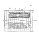
- FIG. 2 is an explanatory view illustrating the internal structure of the conveyor belt of FIG. 1 in plan view.
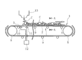
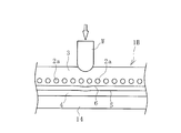
- FIG. 3 is an explanatory view illustrating the belt conveyor apparatus to which the conveyor belt of FIG. 4 is a cross-sectional view taken along the line AA in FIG.
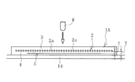
- FIG. 5 is an explanatory view illustrating the analysis model of the conveyor belt used in the loop coil embedding depth setting method of the present invention in a cross-sectional view.
- FIG. 6 is an explanatory view schematically illustrating a state in which the analysis model of FIG. 5 receives an impact from the upper cover rubber side.
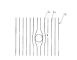
- FIG. 7 is an explanatory diagram schematically illustrating the analysis model of FIG.
- FIG. 6 is a plan view as viewed from the upper cover rubber side.
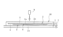
- FIG. 8 is a cross-sectional view illustrating another analysis model.
- FIG. 9 is an explanatory diagram illustrating the internal structure of the analysis model of FIG. 8 in plan view.
- FIG. 10 is an explanatory view schematically illustrating a state in which the analysis model of FIG. 8 receives an impact from the upper cover rubber side in a cross-sectional view.
- FIG. 11 is an explanatory view schematically illustrating the analysis model of FIG. 10 in a plan view as viewed from the upper cover rubber side.
- FIG. 12 is an explanatory view illustrating the state in which the molded body is vulcanized in a cross-sectional view.
- a method for setting the embedding depth of the loop coil in the conveyor belt of the present invention (hereinafter referred to as a setting method) and a method for manufacturing the conveyor belt will be described based on the embodiments shown in the drawings.
- a conveyor belt 1 manufactured by the method of manufacturing a conveyor belt according to the present invention illustrated in FIGS. 1 and 2 includes a core body layer 2, an upper cover rubber 3 disposed with the core body layer 2 sandwiched therebetween, and a lower cover.
- the rubber 4 is provided, and these are integrated through a vulcanization process.
- the conveyor belt 1 is configured by appropriately adding other components such as ear rubbers disposed at both ends in the belt width direction.
- the core body layer 2 includes a plurality of metal cords 2a (for example, steel cords) extending in the belt longitudinal direction and arranged in parallel in the belt width direction. More specifically, the core body layer 2 is covered with a cushion rubber, and the cushion rubber, the upper cover rubber 3 and the lower cover rubber 4 are joined by vulcanization adhesion.
- the metal cord 2a is indicated by a one-dot chain line at the center position.
- the upper cover rubber 3 and the lower cover rubber 4 for example, a rubber composition made of a diene rubber containing at least natural rubber and having good wear resistance with carbon black or the like is used.
- the layer thicknesses of the upper cover rubber 3 and the lower cover rubber 4 are appropriately determined depending on the performance required for the conveyor belt 1, but are determined in the range of, for example, 5 mm to 30 mm.
- Cushion rubber is rubber having excellent adhesion.
- a plurality of loop coils 5 are embedded in the lower cover rubber 4 at intervals in the longitudinal direction of the belt.
- a conductive wire 5a is formed in an annular shape, and a known one can be used.
- the conductive wire 5a may have a specification that is not brazed even if it is braided.
- the loop coil 5 is not limited to a double square shape, and various shapes such as a circular shape and an elliptical shape can also be adopted.
- the embedded plane position of the loop coil 5 is a region including the central portion in the belt width direction.
- the 3 includes a conveyor belt 1, a magnetic field generator 10, and a sensor 11.
- the belt conveyor device 7 illustrated in FIG. The conveyor belt 1 is stretched between the pulleys 8 and 8, and the conveyed product C is put into the upper cover rubber 3 through the chute portion 13. As illustrated in FIG. 4, the conveyor belt 1 is held in a trough shape that protrudes downward by the support roller 9 on the carrier side, so that the loaded conveyed product C is mainly placed at the center in the belt width direction. .
- the magnetic field generator 10 is disposed adjacent to the lower cover rubber 4. For each loop coil 5 that passes in the vicinity of the magnetic field generation unit 10, the magnetic field generation unit 10 transmits an electromagnetic wave, for example. A dielectric current is induced in each loop coil 5 by this electromagnetic wave. If the loop coil 5 is disconnected, no induced current is induced.
- Sensor 11 is arranged adjacent to lower cover rubber 4.
- the sensor 11 is disposed slightly downstream in the traveling direction of the conveyor belt 1 with respect to the magnetic field generator 10. For each loop coil 5 passing in the vicinity of the sensor 11, the sensor 11 detects whether or not an induced current is generated. Data detected by the sensor 11 is transmitted to the control unit 12. Based on the data detected by the sensor 11, the control unit 12 determines that the conveyor belt 1 has not been longitudinally split if an induced current is generated. If the induced current is not generated, the control unit 12 longitudinally splits the conveyor belt 1. Is determined to have occurred. When it is judged that the conveyor belt 1 has a longitudinal tear, the operation of the conveyor belt 1 is stopped and a warning or the like is issued.
- the conveyor belt 1 is subject to impacts and external forces due to the conveyed product C put into the upper cover rubber 3, and the loop coil 5 may be damaged due to these. Therefore, in the setting method of the present invention, an appropriate embedding position is set in which the loop coil 5 is not easily damaged even when these act. Specifically, an appropriate vertical distance (rubber thickness t) between the core layer 2 and the loop coil 5 shown in FIG. 1 is set. This rubber thickness t is the vertical distance between the lower surface of the core layer 2 and the upper surface of the loop coil 5.
- the setting method of the present invention uses a two-dimensional or three-dimensional FEM analysis model 1 ⁇ / b> A of an actual conveyor belt 1.
- the analysis model 1A includes the same components as the actual conveyor belt 1. In the drawing, the same reference numerals as those of the actual conveyor belt 1 are given to the respective components of the analysis model 1A.
- material property values Young's modulus, Poisson's ratio, etc.
- the vertical stress and deformation generated in the loop coil 5 are calculated by FEM analysis.
- the specification and fall height of the fallen object W are appropriately determined based on the actual use conditions of the conveyor belt 1 (the shape and weight of the transported object C) and the like.
- the analysis model 1A is in a condition of being horizontally placed on a flat rigid body 14 such as a steel plate.
- the analysis model 1A can be set to a condition in which the analysis model 1A is supported by the support roller 9 with a gap in the longitudinal direction of the belt as in the actual belt conveyor device 7, but the entire analysis model 1A is placed on the rigid body 14. By doing so, since it becomes a severe condition which is easy to damage the loop coil 5, it is possible to set a more appropriate embedment depth position.
- the upper cover rubber 3 and the loop coil 5 are locally distorted and deformed in a range corresponding to the fall point of the fallen object W.
- the metal cord 2a is displaced in the belt width direction.
- the maximum stress and the maximum deformation amount generated in the loop coil 5 at this time are calculated.
- This analysis is performed by changing the embedded depth position (rubber thickness t) of the loop coil 5.
- the relationship between each embedding depth position and the maximum stress or maximum deformation amount is grasped, the range where the maximum stress or the maximum deformation amount is minimized is grasped, and this range is determined by the actual conveyor belt 1.
- the loop coil 5 is set to an appropriate embedment depth position.
- the parallel metal cords 2a are joined by a cushion rubber interposed between the gaps. Is elastically deformed. Therefore, since the force that restrains the displacement of the metal cord 2a in the belt width direction is weak, the metal cord 2a is locally displaced in the belt width direction, and the distance between the metal cords 2a in the belt width direction is widened.
- the displacement amount of the metal cord 2a in the belt width direction correlates with the maximum stress and the maximum deformation amount generated in the loop coil 5.
- an appropriate embedment depth position of the loop coil 5 can be set.
- an appropriate embedment depth of the loop coil 5 is obtained by using the amount of displacement of the metal cord 2a in the belt width direction as the amount of change corresponding to at least one of the main stress or deformation amount generated in the loop coil 5 in this way. The position may be set.
- an appropriate embedding depth that can improve the durability of the loop coil 5 in the actual conveyor belt 1 is set without manufacturing and testing many samples. It becomes possible. In the development stage of the conveyor belt 1, it is very useful because an appropriate embedment depth position of the loop coil 5 can be grasped according to the specifications of the conveyor belt 1 (rubber type, metal cord type, etc.).
- the analysis model 1A may be three-dimensional or two-dimensional, but by making it two-dimensional, the time required for model production can be significantly reduced. If the correlation between the displacement of the metal cord 2a in the belt width direction and the maximum stress or maximum deformation generated in the loop coil 5 can be sufficiently grasped, the appropriate embedment depth position of the loop coil 5 can be determined by the two-dimensional analysis model 1. Can be set with high accuracy.
- FIGS. 8 and 9 Another analysis model 1B illustrated in FIGS. 8 and 9 can also be used.
- a protective layer 6 is embedded in the lower cover rubber 4 at a predetermined depth between the upper and lower sides of the core layer 2 and the loop coil 5 with respect to the analysis model 1A described above. That is, the protective layer 6 is embedded in the lower cover rubber 4 with an interval in the belt longitudinal direction.
- the protective layer 6 has a specification in which the elongation is smaller (modulus is larger) than the rubber used in the conveyor belt 1 under the same conditions.
- a protective layer 6 having a thickness of 0.2 mm to 3.0 mm is used.
- the protective layer 6 is disposed so as to cover the entire range of the corresponding loop coil 5 (the loop coil 5 arranged closest to the protective layer 6) in a plan view as viewed from the upper cover rubber 3 side.
- the metal cord 2 a is indicated by a one-dot chain line at the center position, and illustration is omitted in a range corresponding to the protective layer 6.
- the lower protective layer 6 is partially cut away.
- the protective layer 6 can be formed of various materials such as natural fiber, resin, metal and the like.
- the structure of the protective layer 6 can employ various structures such as a woven structure and a film shape. Examples of the woven structure include a plain woven structure, a weave woven structure, a twill woven structure, and a satin woven structure.
- the protective layer 6 is formed of a plurality of wires 6a.
- a desired wire 6a such as natural fiber, resin fiber, or metal fiber can be used. Since the protective layer 6 has a plain weave structure, a plurality of wires 6a extending in the belt width direction are arranged in parallel in the belt longitudinal direction. Therefore, the wire 6a extending in the belt width direction is in a state of intersecting with the metal cord 2a arranged in parallel in the belt width direction.
- the upper cover rubber 3 and the loop coil 5 are locally distorted and slightly deformed in a range corresponding to the fall point of the fallen object W, but the metal cord 2a hardly displaces in the belt width direction.
- the maximum stress and the maximum deformation amount generated in the loop coil 5 at this time are calculated. This analysis is performed by changing the embedded depth position (rubber thickness t) of the loop coil 5. As a result, the relationship between each embedding depth position and the maximum stress or maximum deformation amount is grasped, the range where the maximum stress or the maximum deformation amount is minimized is grasped, and this range is determined by the actual conveyor belt 1.
- the loop coil 5 is set to an appropriate embedment depth position.
- the protective layer 6 since the protective layers 6 are arranged so as to cover the metal cords 2a arranged in parallel, the protective layer 6 functions to bind and restrain the metal cords 2a adjacent in the belt width direction. is doing. Therefore, as shown in FIGS. 10 and 11, when an impact or external force is applied to the analysis model 1B, the displacement of the metal cord 2a in the belt width direction is suppressed as compared to the previous analysis model 1A.
- the conveyor belt 1 is manufactured by placing the molded body 1C in the molds 15 and vulcanizing the molded body 1C.
- the loop coil 5 is embedded at an appropriate embedding position set using the analysis model 1B, and a predetermined depth between the upper and lower sides of the core layer 2 and the loop coil 5 is embedded.
- the molded body 1C of the unvulcanized conveyor belt in which the protective layer 6 is embedded in the lower cover rubber 4 is formed.
- the conveyor belt 1 is manufactured by placing the molded body 1C in the molds 15 and vulcanizing the molded body 1C.
- the conveyor belt 1 manufactured in this way has a loop coil 5 embedded in an appropriate embedment position set using the analysis models 1A and 1B. Therefore, it becomes easy to prevent the loop coil 5 from being damaged due to an impact or an external force caused by the conveyed product C thrown into the upper cover rubber 3. Accordingly, it is advantageous to avoid the misconception that the loop coil 5 is damaged even if the conveyor belt 1 is not longitudinally split.
- the protective layer 6 when the protective layer 6 is provided as in the above analysis model 1B, the belt width direction of the metal cord 2a even if a local impact or external force is applied by the conveyed object C or the like. The displacement to is suppressed. Along with this, the acting impact and external force are widely dispersed in the metal cord 2a.
- the protective layer 6 also absorbs and relaxes impacts and external forces. Therefore, even if a large impact or external force is locally applied to the conveyor belt 1, the loop coil 5 is hardly damaged, and the durability is further improved. Therefore, it is more advantageous to avoid the situation that the loop coil 5 is damaged even if the conveyor belt 1 is not longitudinally split, and the occurrence of the longitudinal tear of the conveyor belt 1 is more accurately detected. Is possible.
- each protective layer 6 is embedded in the lower cover rubber 4 with an interval in the belt longitudinal direction, an increase in the weight of the conveyor belt 1 due to the provision of the protective layer 6 can be suppressed. Deterioration of flexibility can also be avoided. Since these have a great influence on reducing the energy required for operating the conveyor belt 1, they contribute to energy saving.
- the protective layer was set to a plain weave structure made of nylon fibers. However, it was found that in the analysis model 1B, the main stress and deformation amount generated in the loop coil 5 are about 60% in the analysis model 1A.
Landscapes
- Engineering & Computer Science (AREA)
- Mechanical Engineering (AREA)
- Belt Conveyors (AREA)
- Control Of Conveyors (AREA)
Abstract
ループコイルの耐久性を向上させることができるコンベヤベルトでの埋設深さを、多数のサンプルを用いて試験することなく設定できるループコイルの埋設深さの設定方法およびこのループコイルを埋設したコンベヤベルトの製造方法を提供する。実際のコンベヤベルト1の二次元または三次元のFEM解析モデル1Aを作製して、この解析モデル1Aでの上カバーゴム3の上方からこの上カバーゴム3に対して所定仕様の落下物Wを落下させた際に、この解析モデル1Aでのループコイル5に生じる主応力または変形量の少なくとも一方に基づいて、実際のコンベヤベルト1でのループコイル6の適切な埋設深さ、即ち心体層2とループコイル5との間のゴム厚tを設定する。
Description
本発明は、コンベヤベルトの縦裂きを検知するループコイルの耐久性を向上させることができるコンベヤベルトでのループコイルの埋設深さを、多数のサンプルを用いて試験することなく設定できるループコイルの埋設深さの設定方法およびこのループコイルを埋設したコンベヤベルトの製造方法に関するものである。
コンベヤベルトの縦裂き(ベルト長手方向に連続する亀裂)を検知するため、ループコイルを埋設したコンベヤベルトが知られている(例えば特許文献1、2参照)。このコンベヤベルトでは、コンベヤベルトに隣接して配置されたセンサが、センサの近傍を通過するループコイルに生じている誘導電流を検知する。鋭利な搬送物等がコンベヤベルトに突き刺さって縦先きが発生した場合にはループコイルが損傷するため、ループコイルには誘導電流が生じなくなる。この場合、センサはループコイルが近傍を通過したにも拘らず誘導電流を検知しない。そのため、センサによる誘導電流の検知の有無によって、コンベヤベルトに縦裂きが発生しているか否かを判断することができる。センサの検知に基づいて縦裂きが発生していると判断した場合は、コンベヤベルトの稼働を停止させて縦裂きの拡大を防止する。
コンベヤベルトには、投入される搬送物等によって局部的な衝撃や外力が作用する。その衝撃や外力によってコンベヤベルトに縦裂きが発生していなくても、ループコイルが損傷することがある。このようにループコイルが損傷をした場合、センサは近傍をループコイルが通過しても誘導電流を検知することがない。そのため、センサの検知に基づいて判断すると、コンベヤベルトに縦裂きが発生していると誤認することになる。
本願の発明者による種々の分析、試験等の結果、下カバーゴムにおけるループコイルの埋設深さ位置と、ループコイルの損傷具合との間には、高い相関関係があることが判明した。しかしながら、下カバーゴムにおけるループコイルの埋設深さ位置を異ならせたサンプルを多数作製し、これらサンプルに対して衝撃を付与してループコイルの損傷具合を確認するとなれば、多大な工数(時間および費用)を要する。
本発明の目的は、コンベヤベルトの縦裂きを検知するループコイルの耐久性を向上させることができるコンベヤベルトでのループコイルの埋設深さを、多数のサンプルを用いて試験することなく設定できるループコイルの埋設深さの設定方法およびこのループコイルを埋設したコンベヤベルトの製造方法を提供する。
上記目的を達成するため本発明のコンベヤベルトでのループコイルの埋設深さの設定方法は、ベルト長手方向に延在する複数本の金属コードがベルト幅方向に並列されて構成された心体層と、この心体層を挟んで上下にそれぞれ配置された上カバーゴムおよび下カバーゴムと、この下カバーゴムにベルト長手方向に間隔をあけて埋設された複数のループコイルとを備えたコンベヤベルトにおける前記ループコイルの埋設深さ位置の設定方法であって、前記コンベヤベルトの二次元または三次元のFEM解析モデルを作製し、この解析モデルでの上カバーゴムの上方からこの上カバーゴムに対して所定仕様の落下物を落下させた際に前記解析モデルでのループコイルに生じる主応力または変形量の少なくとも一方に基づいて、前記コンベヤベルトのループコイルの埋設深さを設定することを特徴とする。
本発明のコンベヤベルトの製造方法は、上記のループコイルの埋設深さの設定方法により設定された埋設深さ位置に前記ループコイルを埋設した未加硫の前記コンベヤベルトの成形体を成形し、この成形体を加硫して前記コンベヤベルトを製造することを特徴とする。
本発明のループコイルの埋設深さの設定方法によれば、実際のコンベヤベルトの上カバーゴムの上方から上カバーゴムに向かって搬送物が投入されてループコイルに局部的に衝撃や外力が作用する際の状況を、実際のコンベヤベルトの二次元または三次元のFEM解析モデルを利用して再現することができる。この解析モデルでのループコイルに生じる主応力または変形量の少なくとも一方に基づいて、実際のコンベヤベルトにおいてループコイルに生じる主応力または変形量が小さくなる適切なループコイルの埋設位置を把握できる。そのため、多数のサンプルを用いて試験をしなくても、実際のコンベヤベルトにおいてループコイルの耐久性を向上させることができる適切な埋設深さを設定することができる。
また、本発明のコンベヤベルトの製造方法によれば、上記の設定方法によって設定された適切な埋設位置にループコイルが埋設されたコンベヤベルトを製造することができる。したがって、上カバーゴムに投入される搬送物による衝撃や外力に起因するループコイルの損傷を防止し易くなる。これに伴い、コンベヤベルトに縦裂きが発生していなくても、ループコイルが損傷しているという誤認を回避するには有利になる。
以下、本発明のコンベヤベルトでのループコイルの埋設深さの設定方法(以下、設定方法という)およびコンベヤベルトの製造方法を図に示した実施形態に基づいて説明する。
図1、図2に例示する本発明のコンベヤベルトの製造方法により製造されたコンベヤベルト1は、心体層2と、心体層2を上下に挟んで配置される上カバーゴム3と下カバーゴム4とを備えていて、これらが加硫工程を経て一体化している。コンベヤベルト1は、その他、ベルト幅方向両端部に配置される耳ゴム等、他の構成要素が適宜追加されて構成される。
心体層2は、ベルト長手方向に延在する多数本の金属コード2a(例えばスチールコード)がベルト幅方向に並列して構成されている。詳述すると、心体層2はクッションゴムにより被覆されていて、このクッションゴムと上カバーゴム3および下カバーゴム4とが加硫接着により接合されている。尚、図2ではコンベヤベルト1の内部構造を理解し易くするため、金属コード2aをその中心位置で一点鎖線によって示している。
上カバーゴム3、下カバーゴム4としては、例えば、少なくとも天然ゴムを含むジエン系ゴムからなり、カーボンブラックなどによって耐摩耗性を良好にしたゴム組成物が用いられる。上カバーゴム3および下カバーゴム4の層厚は、コンベヤベルト1に要求される性能によって適宜決定されるが例えば5mm以上30mm以下の範囲で決定される。クッションゴムは接着性に優れるゴムである。
下カバーゴム4にはベルト長手方向に間隔をあけて複数のループコイル5が埋設されている。ループコイル5は、例えば導電線5aが環状に形成されたものであり、公知のものを用いることができる。この導電線5aは波状に癖付けされていても癖付けされていない仕様でもよい。ループコイル5は二重の四角形状に限らず、円形状、楕円形状など様々な形状を採用することもできる。ループコイル5の埋設平面位置はベルト幅方向中央部を含む領域になる。
図3に例示するベルトコンベヤ装置7は、コンベヤベルト1と、磁界発生部10と、センサ11とを備えている。コンベヤベルト1はプーリ8、8の間に張設されて、搬送物Cはシュート部13を通じて上カバーゴム3に投入される。図4に例示するようにコンベヤベルト1はキャリア側では、支持ローラ9によって下方に突出するトラフ状に保持されるので、投入された搬送物Cは主にベルト幅方向中央部に載置される。
磁界発生部10は下カバーゴム4に隣接配置される。磁界発生部10の近傍を通過するそれぞれのループコイル5に対して、磁界発生部10は例えば電磁波を発信する。この電磁波によってそれぞれのループコイル5には誘電電流が誘起される。ループコイル5が断線していると誘導電流は誘起されない。
センサ11は下カバーゴム4に隣接配置される。センサ11は磁界発生部10に対してコンベヤベルト1の進行方向の若干下流側に配置される。センサ11の近傍を通過するそれぞれのループコイル5に対して、センサ11は誘導電流が発生しているか否か検知する。センサ11による検知データは制御部12に送信される。制御部12は、センサ11による検知データに基づいて、誘導電流が発生していればコンベヤベルト1に縦裂きが生じてないと判断し、誘導電流が発生していなければコンベヤベルト1に縦裂きが生じていると判断する。コンベヤベルト1に縦裂きが生じていると判断した場合は、コンベヤベルト1の稼働を停止し、警告等を発する。
コンベヤベルト1には、上カバーゴム3に投入される搬送物Cによって衝撃や外力が作用し、これらに起因してループコイル5が損傷することがある。そこで、本発明の設定方法では、これらが作用してもループコイル5が損傷し難い適切な埋設位置を設定する。具体的には、図1に示す心体層2とループコイル5との適切な上下間隔(ゴム厚t)を設定する。このゴム厚tは、心体層2の下面とループコイル5の上面との上下間隔である。
図5に例示するように、本発明の設定方法では実際のコンベヤベルト1の二次元または三次元のFEM解析モデル1Aを用いる。この解析モデル1Aは、実際のコンベヤベルト1と同じ構成要素を備えている。図面では解析モデル1Aのそれぞれの構成要素には、実際のコンベヤベルト1の構成要素と同じ符号を付している。解析モデル1Aでは、それぞれの構成要素についてFEM解析に必要な材料物性値(ヤング率、ポアソン比等)が設定されていて、解析を行う演算装置に入力されている。
作製した解析モデル1Aでは、上カバーゴム3の上方からこの上カバーゴム3に対して所定仕様の落下物Wを落下させた際にループコイル5に生じる主応力または変形量の少なくとも一方、或いは、主応力または変形量の少なくとも一方に対応する変化量を演算装置により算出する。例えば、ループコイル5に生じる鉛直方向の応力や変形量をFEM解析により算出する。落下物Wの仕様や落下高さは、実際のコンベヤベルト1の使用条件(搬送物Cの形状や重さ)等に基づいて適宜決定される。
この実施形態では、解析モデル1Aを、鋼板などの平坦な剛体14に水平に載置した条件にしている。解析モデル1Aを、実際のベルトコンベヤ装置7のように支持ローラ9によってベルト長手方向に間隔をあけて支持した条件にすることもできるが、解析モデル1Aの全体を剛体14に載置した条件にすることで、ループコイル5に対しては損傷し易い厳しい条件になるので、より適切な埋設深さ位置を設定できる。
解析モデル1Aにおいて、図6に例示するように落下物Wを自由落下させると、落下物Wの落下点に対応する範囲では、上カバーゴム3およびループコイル5が局部的に下方に歪んで変形し、金属コード2aはベルト幅方向に変位する。この時のループコイル5に生じる最大応力や最大変形量を算出する。この解析を、ループコイル5の埋設深さ位置(ゴム厚t)を変えて行う。これにより、それぞれの埋設深さ位置と、最大応力や最大変形量との関係を把握して、最大応力または最大変形量が最小になる範囲を把握し、この範囲を実際のコンベヤベルト1でのループコイル5の適切な埋設深さ位置に設定する。
図6、7に例示するように解析モデル1Aに衝撃や外力が作用した際には、並列している金属コード2aどうしは、互いのすき間に介在するクッションゴムによって接合されているが、クッションゴムは弾性変形する。それ故、金属コード2aのベルト幅方向への変位を拘束する力が弱いので、局所的に金属コード2aがベルト幅方向に変位して、金属コード2aどうしのベルト幅方向間隔が広くなる。この金属コード2aのベルト幅方向に対する変位量は、ループコイル5に生じる最大応力や最大変形量と相関する。そこで、この両者(金属コード2aのベルト幅方向に対する変位量と、ループコイル5に生じる最大応力や最大変形量と)の相関関係データを蓄積することにより、金属コード2aのベルト幅方向に対する変位量に基づいて、ループコイル5の適切な埋設深さ位置を設定することもできる。即ち、本発明では、このようにループコイル5に生じる主応力または変形量の少なくとも一方に対応する変化量として、金属コード2aのベルト幅方向に対する変位量を用いてループコイル5の適切な埋設深さ位置を設定してもよい。
このように本発明の設定方法では、多数のサンプルを製造して試験をしなくても、実際のコンベヤベルト1においてループコイル5の耐久性を向上させることができる適切な埋設深さを設定することが可能になる。コンベヤベルト1の開発段階において、コンベヤベルト1の仕様(ゴムの種種、金属コードの種類など)に応じてループコイル5の適切な埋設深さ位置を把握できるので、非常に有益である。
解析モデル1Aは、三次元でも二次元でもよいが、二次元にすることによりモデル作製に要する時間を大幅に削減できる。金属コード2aのベルト幅方向に対する変位量とループコイル5に生じる最大応力や最大変形量との相関関係を十分に把握できれば、二次元の解析モデル1によって、ループコイル5の適切な埋設深さ位置を精度よく設定することが可能になる。
図8、9に例示する別の解析モデル1Bを用いることもできる。この解析モデル1Bは、上述した解析モデル1Aに対して、心体層2とループコイル5との上下間の所定深さで下カバーゴム4に保護層6が埋設されている。即ち、保護層6はベルト長手方向に間隔をあけて下カバーゴム4に埋設されている。保護層6は、コンベヤベルト1に使用されているゴムよりも、同じ条件下で伸びが小さい(モジュラスが大きい)仕様である。実際のコンベヤベルト1では、例えば厚さが0.2mm以上3.0mm以下の保護層6が使用される。
保護層6は、上カバーゴム3側から見た平面視で、その保護層6が対応するループコイル5(その保護層6に最も近接配置されているループコイル5)の全範囲を覆って配置されている。尚、図9では解析モデル1Bの内部構造を理解し易くするため、金属コード2aをその中心位置で一点鎖線によって示し、保護層6に対応する範囲では図示を省略している。また、図9では下段の保護層6を一部切り欠いて示している。
実際のコンベヤベルト1では、保護層6は、天然繊維、樹脂、金属等の様々な材質により形成することができる。保護層6の構造は、織構造やフィルム状など様々な構造を採用することができる。織構造としては、平織構造、すだれ織構造、綾織構造、朱子織構造などを例示できる。
この解析モデル1Bでは、保護層6は複数の線材6aにより形成されている。線材6aとしては、天然繊維、樹脂繊維や金属繊維など所望の線材6aを用いることができる。この保護層6は、平織構造なので、ベルト幅方向に延在する複数本の線材6aがベルト長手方向に並列されている。そのため、ベルト幅方向に延在する線材6aが、ベルト幅方向に並列している金属コード2aと交差した状態になっている。
図10に例示するように落下物Wを自由落下させると、落下物Wの落下点に対応する範囲では、上カバーゴム3およびループコイル5が局部的に多少下方に歪んで変形するが金属コード2aはベルト幅方向にはほとんど変位しない。この時のループコイル5に生じる最大応力や最大変形量を算出する。この解析を、ループコイル5の埋設深さ位置(ゴム厚t)を変えて行う。これにより、それぞれの埋設深さ位置と、最大応力や最大変形量との関係を把握して、最大応力または最大変形量が最小になる範囲を把握し、この範囲を実際のコンベヤベルト1でのループコイル5の適切な埋設深さ位置に設定する。
この解析モデル1Bでは、保護層6が並列している金属コード2aどうしを覆う状態で配置されているので、保護層6がベルト幅方向に隣り合う金属コード2aどうしを束ねて拘束する機能を発揮している。そのため、図10、11に例示するように解析モデル1Bに衝撃や外力が作用した際には、先の解析モデル1Aに比して、金属コード2aのベルト幅方向へ変位が抑制される。
この解析モデル1Bにおいても、先の解析モデル1Aに適用した種々の条件、改良を行うことができる。
本発明のコンベヤベルトの製造方法では、図12に例示するように、上記の解析モデル1Aを用いて設定した適切な埋設深さ位置にループコイル5を埋設した未加硫のコンベヤベルトの成形体1Cを成形する。次いで、この成形体1Cをモールド15、15の中に配置して加硫することにより、コンベヤベルト1を製造する。
本発明の別のコンベヤベルトの製造方法では、上記の解析モデル1Bを用いて設定した適切な埋設位置にループコイル5を埋設し、心体層2とループコイル5との上下間の所定深さで下カバーゴム4に保護層6を埋設した未加硫のコンベヤベルトの成形体1Cを成形する。次いで、この成形体1Cをモールド15、15の中に配置して加硫することにより、コンベヤベルト1を製造する。
このようにして製造されたコンベヤベルト1は、解析モデル1A、1Bを用いて設定された適切な埋設位置にループコイル5が埋設されている。そのため、上カバーゴム3に投入される搬送物Cによる衝撃や外力に起因するループコイル5の損傷を防止し易くなる。これに伴い、コンベヤベルト1に縦裂きが発生していなくても、ループコイル5が損傷しているという誤認を回避するには有利になる。
特に、実際のコンベヤベルト1において、上記の解析モデル1Bのように保護層6を設けた仕様にすると、搬送物C等によって局部的な衝撃や外力が作用しても金属コード2aのベルト幅方向への変位が抑制される。これに伴い、作用する衝撃や外力が広く金属コード2aに分散する。また、保護層6によっても衝撃や外力が吸収、緩和される。そのため、コンベヤベルト1に局部的に大きな衝撃や外力が作用してもループコイル5が損傷し難くなり、耐久性が一段と向上する。それ故、コンベヤベルト1に縦裂きが発生していなくてもループコイル5が損傷するという事態を回避するには益々有利になり、コンベヤベルト1の縦裂きの発生の検知をより精度よく行うことが可能になる。
加えて、それぞれの保護層6は、下カバーゴム4にベルト長手方向に間隔をあけて埋設されているので、保護層6を設けたことによるコンベヤベルト1の重量増加を抑制することができ、屈曲性の悪化も回避できる。これらのことは、コンベヤベルト1の稼働に要するエネルギを削減することに大きく影響するため省エネルギ化にも寄与する。
尚、保護層6を下カバーゴム4にベルト長手方向に間隔をあけて埋設した仕様にするには、コンベヤベルト1の成形工程において、それぞれのループコイル5と一緒にそれぞれの保護層6を下カバーゴム4に配置すればよい。そのため、この仕様で製造する際の工数は、保護層6を埋設しない仕様の場合に対してほとんど増加しないで済む。
図5に例示した解析モデル1Aを用いて、一般的なコンベヤベルトについて適切なループコイル5の埋設深さ位置を算出すると、ループコイル5を心体層2の下面から下カバーゴム4のゴム厚Tの30%以上80%以下の位置(ゴム厚t=Tの30%以上80%以下)、より好ましくは50%以上60%以下の位置になることが分かった。また、心体層2とループコイル5との上下間隔(ゴム厚t)は5mm以上にするとよいことが分かった。
また、解析モデル1Bを用いて、上記の解析モデル1Aと同じ条件下で適切なループコイル5の埋設深さ位置を算出すると、上記の解析モデル1Aと概ね同じであった。この時、保護層は、ナイロン繊維からなる平織構造に設定した。ただし、解析モデル1Bでは、ループコイル5に生じる主応力および変形量が解析モデル1Aでの60%程度になることが分かった。
1 コンベヤベルト
1A、1B 解析モデル
1C 成形体
2 心体層
2a 金属コード
3 上カバーゴム
4 下カバーゴム
5 ループコイル
5a 導電線
6 保護層
6a 線材
7 ベルトコンベヤ装置
8 プーリ
9 支持ローラ
10 磁界発生部
11 センサ
12 制御部
13 シュート部
14 剛体
15 モールド
C 搬送物
W 落下物
1A、1B 解析モデル
1C 成形体
2 心体層
2a 金属コード
3 上カバーゴム
4 下カバーゴム
5 ループコイル
5a 導電線
6 保護層
6a 線材
7 ベルトコンベヤ装置
8 プーリ
9 支持ローラ
10 磁界発生部
11 センサ
12 制御部
13 シュート部
14 剛体
15 モールド
C 搬送物
W 落下物
Claims (6)
- ベルト長手方向に延在する複数本の金属コードがベルト幅方向に並列されて構成された心体層と、この心体層を挟んで上下にそれぞれ配置された上カバーゴムおよび下カバーゴムと、この下カバーゴムにベルト長手方向に間隔をあけて埋設された複数のループコイルとを備えたコンベヤベルトにおける前記ループコイルの埋設深さ位置の設定方法であって、
前記コンベヤベルトの二次元または三次元のFEM解析モデルを作製し、この解析モデルでの上カバーゴムの上方からこの上カバーゴムに対して所定仕様の落下物を落下させた際に前記解析モデルでのループコイルに生じる主応力または変形量の少なくとも一方に基づいて、前記コンベヤベルトのループコイルの埋設深さを設定することを特徴とするコンベヤベルトでのループコイルの埋設深さの設定方法。 - 前記解析モデルを剛体の上に載置した条件下で前記落下物を落下させる請求項1に記載のコンベヤベルトでのループコイルの埋設深さの設定方法。
- 前記主応力または変形量に対応する前記解析モデルでの金属コードのベルト幅方向への変位量を用いて前記ループコイルの埋設深さを設定する請求項1または2に記載のコンベヤベルトでのループコイルの埋設深さの設定方法。
- 前記解析モデルとして、心体層とループコイルとの上下間の所定深さで下カバーゴムに保護層を埋設したモデルを用いる請求項1~3のいずれかに記載のコンベヤベルトでのループコイルの埋設深さの設定方法。
- 請求項1~3のいずれかに記載のループコイルの埋設深さの設定方法により設定された埋設深さ位置に前記ループコイルを埋設した未加硫の前記コンベヤベルトの成形体を成形し、この成形体を加硫して前記コンベヤベルトを製造するベルトコンベヤの製造方法。
- 請求項4に記載のループコイルの埋設深さの設定方法により設定された埋設深さ位置に前記ループコイルを埋設し、前記心体層と前記ループコイルとの上下間の所定深さで前記下カバーゴムに前記保護層を埋設した未加硫の前記コンベヤベルトの成形体を成形し、この成形体を加硫して前記コンベヤベルトを製造するベルトコンベヤの製造方法。
Priority Applications (3)
| Application Number | Priority Date | Filing Date | Title |
|---|---|---|---|
| DE112017005938.0T DE112017005938B4 (de) | 2016-11-24 | 2017-10-05 | Verfahren zum festlegen der einbettungstiefe von schleifenspulen in einem förderband und verfahren zum herstellen eines förderbandes |
| CN201780065587.6A CN109996744B (zh) | 2016-11-24 | 2017-10-05 | 传送带中的环状线圈的埋设深度的设定方法以及传送带的制造方法 |
| US16/463,343 US10569488B2 (en) | 2016-11-24 | 2017-10-05 | Method for setting loop coil embedding depth in conveyor belt, and method for manufacturing conveyor belt |
Applications Claiming Priority (2)
| Application Number | Priority Date | Filing Date | Title |
|---|---|---|---|
| JP2016228085A JP6819242B2 (ja) | 2016-11-24 | 2016-11-24 | コンベヤベルトでのループコイルの埋設深さの設定方法およびコンベヤベルトの製造方法 |
| JP2016-228085 | 2016-11-24 |
Publications (1)
| Publication Number | Publication Date |
|---|---|
| WO2018096800A1 true WO2018096800A1 (ja) | 2018-05-31 |
Family
ID=62195057
Family Applications (1)
| Application Number | Title | Priority Date | Filing Date |
|---|---|---|---|
| PCT/JP2017/036285 Ceased WO2018096800A1 (ja) | 2016-11-24 | 2017-10-05 | コンベヤベルトでのループコイルの埋設深さの設定方法およびコンベヤベルトの製造方法 |
Country Status (5)
| Country | Link |
|---|---|
| US (1) | US10569488B2 (ja) |
| JP (1) | JP6819242B2 (ja) |
| CN (1) | CN109996744B (ja) |
| DE (1) | DE112017005938B4 (ja) |
| WO (1) | WO2018096800A1 (ja) |
Families Citing this family (1)
| Publication number | Priority date | Publication date | Assignee | Title |
|---|---|---|---|---|
| JP7564426B2 (ja) * | 2020-07-02 | 2024-10-09 | 横浜ゴム株式会社 | コンベヤベルトの縦裂き検出装置および方法 |
Citations (4)
| Publication number | Priority date | Publication date | Assignee | Title |
|---|---|---|---|---|
| JP2002228525A (ja) * | 2001-01-31 | 2002-08-14 | Bando Chem Ind Ltd | 搬送物からの衝撃を入力条件とする応力解析方法 |
| JP2005075617A (ja) * | 2003-09-03 | 2005-03-24 | Yokohama Rubber Co Ltd:The | コンベヤベルトのシミュレーション方法 |
| US20130081929A1 (en) * | 2011-09-30 | 2013-04-04 | Veyance Technologies, Inc. | Superelastic low rolling resistance conveyor belt |
| JP2016185879A (ja) * | 2015-03-27 | 2016-10-27 | バンドー化学株式会社 | スチールコードコンベヤベルトの縦裂検出装置及びスチールコードコンベヤベルトの縦裂検出システム |
Family Cites Families (8)
| Publication number | Priority date | Publication date | Assignee | Title |
|---|---|---|---|---|
| DE3347570A1 (de) * | 1983-12-30 | 1985-07-11 | Conrad Scholtz Ag, 2000 Hamburg | Foerdergurt mit eingebetteten leiterschleifen und verfahren zu seiner herstellung |
| JP2014028682A (ja) * | 2012-07-31 | 2014-02-13 | Bridgestone Corp | コンベヤベルトおよびコンベヤベルト装置 |
| JP2014031241A (ja) | 2012-08-02 | 2014-02-20 | Bridgestone Corp | コンベヤベルトおよびコンベヤベルト装置 |
| JP5915456B2 (ja) * | 2012-08-23 | 2016-05-11 | 横浜ゴム株式会社 | コンベヤベルト |
| JP2015071493A (ja) | 2013-10-04 | 2015-04-16 | 株式会社ブリヂストン | コンベヤベルトおよびコンベヤベルト用環状導電体 |
| JP6668616B2 (ja) * | 2015-06-03 | 2020-03-18 | 横浜ゴム株式会社 | コンベヤベルト |
| JP6790339B2 (ja) * | 2015-08-24 | 2020-11-25 | 横浜ゴム株式会社 | コンベヤベルトのモニタリングシステム |
| JP6743472B2 (ja) * | 2016-04-22 | 2020-08-19 | 横浜ゴム株式会社 | 衝撃試験方法および装置 |
-
2016
- 2016-11-24 JP JP2016228085A patent/JP6819242B2/ja active Active
-
2017
- 2017-10-05 WO PCT/JP2017/036285 patent/WO2018096800A1/ja not_active Ceased
- 2017-10-05 DE DE112017005938.0T patent/DE112017005938B4/de active Active
- 2017-10-05 CN CN201780065587.6A patent/CN109996744B/zh active Active
- 2017-10-05 US US16/463,343 patent/US10569488B2/en not_active Expired - Fee Related
Patent Citations (4)
| Publication number | Priority date | Publication date | Assignee | Title |
|---|---|---|---|---|
| JP2002228525A (ja) * | 2001-01-31 | 2002-08-14 | Bando Chem Ind Ltd | 搬送物からの衝撃を入力条件とする応力解析方法 |
| JP2005075617A (ja) * | 2003-09-03 | 2005-03-24 | Yokohama Rubber Co Ltd:The | コンベヤベルトのシミュレーション方法 |
| US20130081929A1 (en) * | 2011-09-30 | 2013-04-04 | Veyance Technologies, Inc. | Superelastic low rolling resistance conveyor belt |
| JP2016185879A (ja) * | 2015-03-27 | 2016-10-27 | バンドー化学株式会社 | スチールコードコンベヤベルトの縦裂検出装置及びスチールコードコンベヤベルトの縦裂検出システム |
Also Published As
| Publication number | Publication date |
|---|---|
| US10569488B2 (en) | 2020-02-25 |
| DE112017005938B4 (de) | 2021-05-27 |
| JP2018083693A (ja) | 2018-05-31 |
| DE112017005938T5 (de) | 2019-08-08 |
| US20190351633A1 (en) | 2019-11-21 |
| JP6819242B2 (ja) | 2021-01-27 |
| CN109996744A (zh) | 2019-07-09 |
| CN109996744B (zh) | 2020-03-03 |
Similar Documents
| Publication | Publication Date | Title |
|---|---|---|
| US4621727A (en) | Conveyor belt damage sensor | |
| JP4932222B2 (ja) | コンベヤベルトの摩耗検出装置 | |
| CA2684828C (en) | Conveyor belt rip detection system | |
| Moore et al. | Fatigue characterization of 3D printed elastomer material | |
| JP6450164B2 (ja) | マイクロワイヤセンサを備えるコンベヤベルトの裂け目検出システム | |
| KR101536849B1 (ko) | 장치 내에서 무단으로 순환하는 체인의 연신을 측정하기 위한 장치 및 방법 | |
| JP6353321B2 (ja) | ゴム・コード複合体の機械的特性の評価方法 | |
| AU2013297827B2 (en) | Conveyor belt and conveyor belt apparatus | |
| WO2018096801A1 (ja) | コンベヤベルトおよびベルトコンベヤ装置 | |
| CN106241185B (zh) | 磨损检测型传送带及其制备方法 | |
| CN107614400B (zh) | 传送带 | |
| JP2018083693A (ja) | コンベヤベルトでのループコイルの埋設深さの設定方法およびコンベヤベルトの製造方法 | |
| Hansen et al. | Fatigue response of a host structure with interlaced embedded devices | |
| JP2010190578A (ja) | リンクチェーンの伸びの測定方法および装置 | |
| US10712234B2 (en) | Belt and pulley systems and methods of detecting belt damage | |
| JP2015071493A (ja) | コンベヤベルトおよびコンベヤベルト用環状導電体 | |
| JP5756287B2 (ja) | トレッド溝の耐溝底クラック性能の評価方法 | |
| EP3717336B1 (en) | Rubber track wheel path reinforcement | |
| KR20090127404A (ko) | 칩 분할 무단 벨트 | |
| JP6822079B2 (ja) | 耐カット性能の評価のための試験装置 | |
| JP2015202931A (ja) | ゴムベルト | |
| CA3055651C (en) | Conveyor belt with reinforcing block | |
| JP2009222469A (ja) | コンベヤベルト及びコンベヤベルトの製造方法 | |
| JP2022142940A (ja) | 内部残留ひずみを測定する方法およびそのひずみを測定するためのセンサ | |
| JP2015009903A (ja) | パイプコンベヤ用ベルト |
Legal Events
| Date | Code | Title | Description |
|---|---|---|---|
| 121 | Ep: the epo has been informed by wipo that ep was designated in this application |
Ref document number: 17875054 Country of ref document: EP Kind code of ref document: A1 |
|
| 122 | Ep: pct application non-entry in european phase |
Ref document number: 17875054 Country of ref document: EP Kind code of ref document: A1 |