WO2018092842A1 - 遠心圧縮機 - Google Patents
遠心圧縮機 Download PDFInfo
- Publication number
- WO2018092842A1 WO2018092842A1 PCT/JP2017/041260 JP2017041260W WO2018092842A1 WO 2018092842 A1 WO2018092842 A1 WO 2018092842A1 JP 2017041260 W JP2017041260 W JP 2017041260W WO 2018092842 A1 WO2018092842 A1 WO 2018092842A1
- Authority
- WO
- WIPO (PCT)
- Prior art keywords
- housing
- condensed water
- pressure
- compressor
- centrifugal compressor
- Prior art date
- Legal status (The legal status is an assumption and is not a legal conclusion. Google has not performed a legal analysis and makes no representation as to the accuracy of the status listed.)
- Ceased
Links
Images


Classifications
-
- F—MECHANICAL ENGINEERING; LIGHTING; HEATING; WEAPONS; BLASTING
- F02—COMBUSTION ENGINES; HOT-GAS OR COMBUSTION-PRODUCT ENGINE PLANTS
- F02B—INTERNAL-COMBUSTION PISTON ENGINES; COMBUSTION ENGINES IN GENERAL
- F02B33/00—Engines characterised by provision of pumps for charging or scavenging
- F02B33/32—Engines with pumps other than of reciprocating-piston type
- F02B33/34—Engines with pumps other than of reciprocating-piston type with rotary pumps
- F02B33/40—Engines with pumps other than of reciprocating-piston type with rotary pumps of non-positive-displacement type
-
- F—MECHANICAL ENGINEERING; LIGHTING; HEATING; WEAPONS; BLASTING
- F02—COMBUSTION ENGINES; HOT-GAS OR COMBUSTION-PRODUCT ENGINE PLANTS
- F02B—INTERNAL-COMBUSTION PISTON ENGINES; COMBUSTION ENGINES IN GENERAL
- F02B39/00—Component parts, details, or accessories relating to, driven charging or scavenging pumps, not provided for in groups F02B33/00 - F02B37/00
-
- F—MECHANICAL ENGINEERING; LIGHTING; HEATING; WEAPONS; BLASTING
- F02—COMBUSTION ENGINES; HOT-GAS OR COMBUSTION-PRODUCT ENGINE PLANTS
- F02B—INTERNAL-COMBUSTION PISTON ENGINES; COMBUSTION ENGINES IN GENERAL
- F02B39/00—Component parts, details, or accessories relating to, driven charging or scavenging pumps, not provided for in groups F02B33/00 - F02B37/00
- F02B39/02—Drives of pumps; Varying pump drive gear ratio
-
- F—MECHANICAL ENGINEERING; LIGHTING; HEATING; WEAPONS; BLASTING
- F02—COMBUSTION ENGINES; HOT-GAS OR COMBUSTION-PRODUCT ENGINE PLANTS
- F02B—INTERNAL-COMBUSTION PISTON ENGINES; COMBUSTION ENGINES IN GENERAL
- F02B39/00—Component parts, details, or accessories relating to, driven charging or scavenging pumps, not provided for in groups F02B33/00 - F02B37/00
- F02B39/02—Drives of pumps; Varying pump drive gear ratio
- F02B39/08—Non-mechanical drives, e.g. fluid drives having variable gear ratio
- F02B39/10—Non-mechanical drives, e.g. fluid drives having variable gear ratio electric
-
- F—MECHANICAL ENGINEERING; LIGHTING; HEATING; WEAPONS; BLASTING
- F02—COMBUSTION ENGINES; HOT-GAS OR COMBUSTION-PRODUCT ENGINE PLANTS
- F02M—SUPPLYING COMBUSTION ENGINES IN GENERAL WITH COMBUSTIBLE MIXTURES OR CONSTITUENTS THEREOF
- F02M26/00—Engine-pertinent apparatus for adding exhaust gases to combustion-air, main fuel or fuel-air mixture, e.g. by exhaust gas recirculation [EGR] systems
- F02M26/13—Arrangement or layout of EGR passages, e.g. in relation to specific engine parts or for incorporation of accessories
- F02M26/35—Arrangement or layout of EGR passages, e.g. in relation to specific engine parts or for incorporation of accessories with means for cleaning or treating the recirculated gases, e.g. catalysts, condensate traps, particle filters or heaters
-
- F—MECHANICAL ENGINEERING; LIGHTING; HEATING; WEAPONS; BLASTING
- F04—POSITIVE - DISPLACEMENT MACHINES FOR LIQUIDS; PUMPS FOR LIQUIDS OR ELASTIC FLUIDS
- F04D—NON-POSITIVE-DISPLACEMENT PUMPS
- F04D29/00—Details, component parts, or accessories
- F04D29/40—Casings; Connections of working fluid
- F04D29/42—Casings; Connections of working fluid for radial or helico-centrifugal pumps
-
- F—MECHANICAL ENGINEERING; LIGHTING; HEATING; WEAPONS; BLASTING
- F04—POSITIVE - DISPLACEMENT MACHINES FOR LIQUIDS; PUMPS FOR LIQUIDS OR ELASTIC FLUIDS
- F04D—NON-POSITIVE-DISPLACEMENT PUMPS
- F04D29/00—Details, component parts, or accessories
- F04D29/40—Casings; Connections of working fluid
- F04D29/42—Casings; Connections of working fluid for radial or helico-centrifugal pumps
- F04D29/4206—Casings; Connections of working fluid for radial or helico-centrifugal pumps especially adapted for elastic fluid pumps
-
- F—MECHANICAL ENGINEERING; LIGHTING; HEATING; WEAPONS; BLASTING
- F04—POSITIVE - DISPLACEMENT MACHINES FOR LIQUIDS; PUMPS FOR LIQUIDS OR ELASTIC FLUIDS
- F04D—NON-POSITIVE-DISPLACEMENT PUMPS
- F04D29/00—Details, component parts, or accessories
- F04D29/40—Casings; Connections of working fluid
- F04D29/42—Casings; Connections of working fluid for radial or helico-centrifugal pumps
- F04D29/4206—Casings; Connections of working fluid for radial or helico-centrifugal pumps especially adapted for elastic fluid pumps
- F04D29/4213—Casings; Connections of working fluid for radial or helico-centrifugal pumps especially adapted for elastic fluid pumps suction ports
-
- F—MECHANICAL ENGINEERING; LIGHTING; HEATING; WEAPONS; BLASTING
- F04—POSITIVE - DISPLACEMENT MACHINES FOR LIQUIDS; PUMPS FOR LIQUIDS OR ELASTIC FLUIDS
- F04D—NON-POSITIVE-DISPLACEMENT PUMPS
- F04D29/00—Details, component parts, or accessories
- F04D29/70—Suction grids; Strainers; Dust separation; Cleaning
-
- F—MECHANICAL ENGINEERING; LIGHTING; HEATING; WEAPONS; BLASTING
- F04—POSITIVE - DISPLACEMENT MACHINES FOR LIQUIDS; PUMPS FOR LIQUIDS OR ELASTIC FLUIDS
- F04D—NON-POSITIVE-DISPLACEMENT PUMPS
- F04D29/00—Details, component parts, or accessories
- F04D29/70—Suction grids; Strainers; Dust separation; Cleaning
- F04D29/701—Suction grids; Strainers; Dust separation; Cleaning especially adapted for elastic fluid pumps
- F04D29/706—Humidity separation
-
- F—MECHANICAL ENGINEERING; LIGHTING; HEATING; WEAPONS; BLASTING
- F05—INDEXING SCHEMES RELATING TO ENGINES OR PUMPS IN VARIOUS SUBCLASSES OF CLASSES F01-F04
- F05D—INDEXING SCHEME FOR ASPECTS RELATING TO NON-POSITIVE-DISPLACEMENT MACHINES OR ENGINES, GAS-TURBINES OR JET-PROPULSION PLANTS
- F05D2260/00—Function
- F05D2260/60—Fluid transfer
- F05D2260/602—Drainage
Definitions
- This disclosure relates to a centrifugal compressor.
- a turbocharger incorporated in an internal combustion engine of a vehicle As a centrifugal compressor, as described in Patent Document 1, a turbocharger incorporated in an internal combustion engine of a vehicle is known.
- the turbocharger includes a compressor and a turbine.
- This internal combustion engine includes an exhaust gas recirculation device that introduces a part of exhaust gas as EGR (Exhaust Gas Recirculation) gas.
- the exhaust gas recirculation device includes a low pressure EGR passage, and the low pressure EGR passage is connected to a compressor of the turbocharger via an intake passage of the internal combustion engine.
- a trapper is provided between the intake passage and the low-pressure EGR passage to collect condensed water generated from EGR gas or the like.
- a tank for storing condensed water is connected to the trapper.
- a groove portion is provided in the compressor housing of the turbocharger. This groove part is connected to the casing of the trapper via the condensed water passage.
- condensed water may be generated in the housing.
- the condensed water accumulated in the housing is preferably discharged to the outside by some means.
- a large-scale device such as newly installing piping for discharging condensed water to the outside has been separately required.
- the present disclosure describes a centrifugal compressor that can discharge condensed water to the outside with a simple configuration.
- a centrifugal compressor includes a compressor impeller attached to a rotating shaft, and a housing that houses the rotating shaft and the compressor impeller, and the housing is a suction portion provided on the upstream side of the compressor impeller. And a high-pressure part formed on the back side of the compressor impeller and having a pressure higher than the pressure in the suction part when the compressor impeller rotates, and the housing has a high-pressure part and an upstream side of the suction part and the suction part A discharge passage for connecting the low pressure part including the gas flow path is provided.
- the condensed water in the housing can be discharged to the outside with a simple configuration by the discharge mechanism using the pressure difference.
- FIG. 1 is a cross-sectional view illustrating a centrifugal compressor according to an embodiment of the present disclosure.
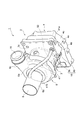
- FIG. 2 is a perspective view showing the centrifugal compressor of FIG.
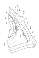
- FIG. 3 is a cross-sectional perspective view showing the inner surface side of the housing.
- FIG. 4 is a cross-sectional perspective view showing the inner surface side of the housing.
- FIG. 5 is a cross-sectional perspective view showing the condensed water storage part and the connection port.
- a centrifugal compressor includes a compressor impeller attached to a rotating shaft, and a housing that houses the rotating shaft and the compressor impeller, and the housing is a suction portion provided on the upstream side of the compressor impeller. And a high-pressure part formed on the back side of the compressor impeller and having a pressure higher than the pressure in the suction part when the compressor impeller rotates, and the housing has a high-pressure part and an upstream side of the suction part and the suction part A discharge passage for connecting the low pressure part including the gas flow path is provided.
- the condensed water in the housing is discharged from the high pressure portion to the low pressure portion through the discharge passage.
- the high pressure portion has a pressure higher than the pressure in the suction portion when the compressor impeller rotates (that is, when the centrifugal compressor is in operation). Since the discharge passage connects the high pressure portion and the low pressure portion, the condensed water can be discharged using the pressure difference. It is only necessary to previously provide a pipe or the like forming the discharge passage in the housing, and it is not necessary to newly install a pipe or the like for discharging condensed water to the outside. With such a discharge mechanism using the pressure difference, the condensed water in the housing can be discharged to the outside with a simple configuration.
- a stator portion is provided around the rotation shaft, the housing is provided on the back side of the compressor impeller, and a peripheral wall portion that supports the core portion of the stator portion, and a compressor impeller for the peripheral wall portion, Includes an end wall portion provided on the opposite side, the high-pressure portion includes an internal space defined by the peripheral wall portion and the end wall portion, and the discharge passage is located on the end wall portion side from the core portion. Connected to space.
- the stator portion is provided in the housing, if the condensed water accumulates in the vicinity of the stator portion, the stator portion may be adversely affected. For example, if the accumulated condensed water freezes while the centrifugal compressor is stopped, there is a risk that a malfunction may occur during restart.
- the discharge passage is connected to the housing on the end wall portion side of the core portion as in the above configuration, the condensed water is unlikely to accumulate near the core portion. Thereby, the bad influence with respect to a stator part can be reduced.
- the housing is included in the high-pressure portion and includes a condensate storage portion formed in the lower portion based on the usage state of the centrifugal compressor. If the condensed water storage part is formed in the lower part of the housing, the condensed water is stored in the condensed water storage part by gravity. Therefore, condensed water can be collected in a fixed place in the housing. When discharging condensed water, condensed water can also be discharged collectively from a condensed water storage part.
- connection port where the discharge passage is connected to the high-pressure portion is provided in the lower part of the housing based on the usage state of the centrifugal compressor.
- Condensed water can evaporate when the inside of the housing becomes hot during operation of the centrifugal compressor. In the state of water vapor, the condensed water can be discharged even if the condensed water discharge port (connection port) is at the top.
- connection port when the temperature in the housing is relatively low, such as when the centrifugal compressor is started, the condensed water may be in a liquid state. If the connection port of the discharge passage is provided in the lower part of the housing, the condensed water can be easily discharged from the connection port using the pressure difference even if the condensed water is in a liquid state.
- the inner wall surface of the housing is provided with a groove extending toward the connection port.
- the condensed water can be collected in the groove portion of the inner wall surface.
- the condensed water can be guided to the connection port through the groove by gravity.
- the discharge passage connects the high pressure portion of the housing and the suction portion of the housing.
- the condensed water is refluxed from the high pressure part to the suction part.
- an electric compressor (an example of a centrifugal compressor) 1 according to a first embodiment will be described with reference to FIG.
- the electric compressor 1 is applied to, for example, an internal combustion engine of a vehicle or a ship.
- the electric compressor 1 includes a compressor 7.
- the electric compressor 1 rotates the compressor impeller 8 by the interaction of the rotor portion 13 and the stator portion 14, compresses a gas such as air, and generates compressed air.
- a motor 5 is formed by the rotor portion 13 and the stator portion 14.
- the electric compressor 1 includes a rotating shaft 12 that is rotatably supported in the housing 2 and a compressor impeller 8 that is attached to a tip end (first end) 12a of the rotating shaft 12.
- the housing 2 includes a motor housing 3 that houses the rotor portion 13 and the stator portion 14, an inverter housing 4 that closes an opening on the second end side (right side in the drawing) of the motor housing 3, and a compressor housing 6 that houses the compressor impeller 8. With.
- the compressor housing 6 is provided on the first end side (the left side in the figure) of the motor housing 3.
- the compressor housing 6 includes a suction port 9, a scroll portion 10, and a discharge port 11.
- the rotor portion 13 is fixed to the central portion of the rotation shaft 12 in the direction of the rotation axis X, and includes one or more permanent magnets (not shown) attached to the rotation shaft 12.
- the stator portion 14 is fixed to the inner surface of the motor housing 3 so as to surround the rotor portion 13. That is, the stator portion 14 is disposed around the rotating shaft 12.
- the stator portion 14 includes a cylindrical core portion 14a disposed so as to surround the rotor portion 13, and a coil portion 14b formed by winding a conductive wire (not shown) around the core portion 14a.
- the electric compressor 1 includes two bearings 20A and 20B that rotatably support the rotary shaft 12 with respect to the housing 2.
- the bearings 20 ⁇ / b> A and 20 ⁇ / b> B are arranged so as to sandwich the motor 5, and support the rotating shaft 12 with both ends.
- the first bearing 20 ⁇ / b> A is held by a partition wall 3 a that is an end of the motor housing 3 on the compressor impeller 8 side.
- the second bearing 20 ⁇ / b> B is held on the inner surface side (compressor impeller 8 side) of the partition wall portion (end wall portion) 4 a of the inverter housing 4.
- the motor housing 3 includes a cylindrical peripheral wall portion 3b that supports the core portion 14a of the stator portion 14, a disk-shaped partition wall portion 3a provided on the first end side of the peripheral wall portion 3b, and a second of the peripheral wall portion 3b. And a flange portion 3c provided on the end side.
- the partition wall portion 3a and the flange portion 3c are in the radial direction of the rotation axis X and extend in a direction perpendicular to the peripheral wall portion 3b.
- the core portion 14a may be within the range in which the peripheral wall portion 3b is provided in the direction of the rotation axis X.
- the core part 14a may be arrange
- the end of the core portion 14a on the partition wall 4a side in the rotation axis X direction may overlap the position where the flange portion 3c is provided in the rotation axis X direction.
- the peripheral wall 3b extends in the rotation axis X direction.
- the partition wall 3a extends radially inward from the peripheral wall 3b.
- a rotating shaft 12 passes through the partition wall 3a.
- the partition 3a holds the first bearing 20A.
- the partition wall 3a faces the back surface 8a of the compressor impeller 8 with a slight gap.
- the second end of the peripheral wall 3 b is open to the inverter housing 4.
- the rotary shaft 12 extends through the opening to the side opposite to the compressor impeller 8.
- the flange portion 3c extends radially outward from the peripheral wall portion 3b.
- the inverter housing 4 has a peripheral wall portion 4b having a first end connected to the flange portion 3c and extending in the direction of the rotation axis X (opposite to the compressor impeller 8), and a partition wall portion closing the opening on the second end side of the peripheral wall portion 4b. 4a and a side wall 4c extending in the direction of the rotation axis X from the periphery of the partition wall 4a.
- the partition wall 4a is a radial direction of the rotation axis X and extends in a direction perpendicular to the peripheral wall 4b.
- the second bearing 20B and the base end portion of the rotary shaft 12 are disposed in the peripheral wall portion 4b.
- a part of the stator part 14 (for example, a part of the coil part 14b, etc.) may be disposed in the peripheral wall part 4b.
- the core portion 14a does not protrude toward the inverter housing 4 side.
- the inverter housing 4 has a mechanism for supplying a drive current to the stator unit 14. That is, the inverter housing 4 is provided with an electrical component group 30 including an inverter and the like.
- a bus bar assembly 32 which is a conductive member that bundles conductive wires connected to the stator portion 14, is provided in the peripheral wall portion 4b.
- the bus bar assembly 32 is disposed in a radially outward space of the second bearing 20B.
- a module 31 that accommodates a control component such as an inverter is fixed to the outer surface side of the partition wall 4a.
- the peripheral wall portion 3b and the peripheral wall portion 4b constitute a peripheral wall portion 16 as the housing 2 as a whole.
- the peripheral wall portion 16 is provided on the back surface 8 a side of the compressor impeller 8 and supports the stator portion 14.
- the partition wall 4 a is provided on the side opposite to the compressor impeller 8 with respect to the peripheral wall 16.
- a predetermined internal space A1 is defined by the partition wall portion 3a, the peripheral wall portion 16, the flange portion 3c, and the partition wall portion 4a.
- the internal space A1 is located on the back surface 8a side of the compressor impeller 8 with the partition wall 3a interposed therebetween.
- the bus bar assembly 32 is disposed in the internal space A1.
- a module installation space A2 is formed by the partition wall portion 4a and the side wall portion 4c.
- the partition wall 4a separates the internal space A1 from the module installation space A2.
- the compressor housing 6 is provided on the upstream side of the compressor impeller 8, provided on the downstream side of the compressor impeller 8, the suction pipe portion 6 a that forms the suction port 9, And a discharge pipe portion 6 c that forms the discharge port 11.
- an extended suction pipe part (suction part) 6b is attached upstream of the suction pipe part 6a.
- the suction pipe portion 6a may have the same length as that when the extended suction pipe portion 6b is provided.
- the extended suction pipe part 6b may be integrated with the suction pipe part 6a and formed as a part of the suction pipe part 6a.
- the pressure inside the suction pipe portion 6a and the extension suction pipe portion 6b (that is, the suction port 9) is relatively low.
- the pressure inside the discharge pipe portion 6c (that is, the discharge port 11) is higher than the pressure inside the suction pipe portion 6a and the extended suction pipe portion 6b, that is, the space upstream of the compressor impeller 8.
- the pressure in the space on the downstream side of the compressor impeller 8 (that is, the scroll portion 10 or the like) is higher than the pressure in the space on the upstream side of the compressor impeller 8.
- a space on the back surface 8a side of the compressor impeller 8 and surrounded by the motor housing 3, the peripheral wall portion 4b of the inverter housing 4 and the partition wall portion 4a has a communication hole (not shown) formed in the partition wall portion 3a. And communicates with a space on the downstream side of the compressor impeller 8. Therefore, the pressure in the space on the rear surface 8 a side of the compressor impeller 8 is close to the discharge pressure during operation of the electric compressor 1 and is higher than the pressure in the space upstream of the compressor impeller 8. That is, on the back surface 8 a side of the compressor impeller 8, a high-pressure portion H is formed that has a higher pressure than the pressure in the suction pipe portion 6 a and the extended suction pipe portion 6 b when the compressor impeller 8 rotates.
- the high-pressure part H includes the internal space A1 described above.
- suction pipe portion 6a and the extension suction pipe portion 6b and the gas flow path upstream of the extension suction pipe portion 6b are connected to the low pressure portion L ( 1).
- the electric compressor 1 of the present embodiment includes a mechanism for discharging condensed water that can accumulate in the housing 2. More specifically, the electric compressor 1 is provided with a discharge passage 50 (see FIGS. 2 and 4) that connects the high pressure portion H and the low pressure portion L described above. In the electric compressor 1, the discharge passage 50 is formed by a discharge pipe 41 disposed outside the housing 2 and connected to the housing 2.
- the discharge pipe 41 connects the motor housing 3 and the compressor housing 6.
- the first end portion 41 a of the discharge pipe 41 is connected to the flange portion 3 c of the motor housing 3.
- the second end 41 b of the discharge pipe 41 is connected to the extended suction pipe 6 b of the compressor housing 6.
- the first end portion 41 a allows the discharge passage 50 in the discharge pipe 41 to communicate with the high pressure portion H.
- the second end portion 41 b allows the discharge passage 50 in the discharge pipe 41 to communicate with the low pressure portion L.
- the second end portion 41b may be connected to the suction pipe portion 6a.
- the first end portion 41a is provided with a socket-like connection portion 41c, and this connection portion 41c is inserted into a through hole formed in the flange portion 3c.
- the connection port 42 at the tip of the connection portion 41c is connected to the internal space A1.
- the second end portion 41b may be integrated with the extended suction pipe portion 6b.
- a socket-like connection portion may be provided at the second end portion 41b, and this connection portion may be inserted into a through hole formed in the extended suction pipe portion 6b.
- the connection form of the discharge pipe 41 is not limited to the above.
- the first end 41 a of the discharge pipe 41 may be connected to a portion (hole) outside the motor housing 3.
- the first end 41a of the discharge pipe 41 only needs to communicate with the internal space A1.
- a connection part such as a nipple that can connect both the first end part 41a side and the second end part 41b side may be provided at a site outside the housing 2.
- connection portion 41c of the discharge pipe 41 is connected to the internal space A1 on the partition wall portion 4a side than the core portion 14a of the stator portion 14. More specifically, the connection portion 41c is connected to the internal space A1 on the partition wall portion 4a side with respect to the end surface 14c of the core portion 14a.
- the connection port 42 is provided in the lower portion of the inverter housing 4.
- the terms “lower part” and “lower part” are used on the basis of the usage state (or mounting state) of the electric compressor 1.
- the “lower part of the inverter housing 4” may be lower than the center (rotation axis X) of the inverter housing 4.
- the inverter housing 4 includes a protruding portion 4e (see FIG. 3) that is a part of the peripheral wall portion 4b and protrudes below the diameter of the peripheral wall portion 3b corresponding to the stator portion 14.
- the connection port 42 of the discharge pipe 41 is connected to the protruding portion 4e.
- the rotation axis X may extend in the lateral direction.
- 3 is a cross-sectional view of the motor housing 3 and the inverter housing 4 cut along a vertical plane including the rotation axis X.
- FIG. FIG. 4 is a cross-sectional view of the motor housing 3 and the inverter housing 4 cut along a horizontal plane including the rotation axis X.
- the discharge pipe 41 connects the high pressure part H and the low pressure part L to return the condensed water accumulated in the high pressure part H of the housing 2 to the low pressure part L when the electric compressor 1 is operated.
- the connection port 42 of the discharge pipe 41 functions as a discharge port when the condensed water is recirculated.
- FIG. 4 is a view showing the lower inner surface side of the motor housing 3 and the inverter housing 4.
- a first groove 43 extending in the direction of the rotation axis X is formed on the inner wall surface 3d of the lower portion (bottom portion) of the peripheral wall portion 3b and the lower portion (bottom portion) of the flange portion 3c.
- a second groove 44 is formed in the inner wall surface 4d at the lower part (bottom part) of the peripheral wall part 4b.
- the second groove portion 44 includes an axial portion 44a formed on the extension line of the first groove portion 43 and extending in the direction of the rotation axis X, and a circumferential portion 44b extending in the circumferential direction continuously to the axial portion 44a.
- a side wall 44c (a part of the second groove 44) extending in the radial direction and the circumferential direction is formed between the circumferential portion 44b and the flange portion 3c.
- a condensate water storage portion 46 that is recessed below the circumferential portion 44b is formed in the protruding portion 4e of the peripheral wall portion 4b.
- the condensate storage portion 46 that is a recess is included in the internal space A ⁇ b> 1 (the high pressure portion H) and is formed in the lower portion of the inner surface of the inverter housing 4.
- the condensed water storage 46 is formed closer to the partition wall 4a than the end surface 14c of the core 14a.
- the connection port 42 is provided so as to face the condensed water storage unit 46.
- the first groove 43 formed at the bottom of the peripheral wall 3b and the flange 3c and the second groove 44 formed at the bottom of the peripheral wall 4b are, for example, , It is continuous with a slight gap formed between them.
- the 1st groove part 43 extended along the rotation axis X direction and the L-shaped 2nd groove part 44 which changes a direction from the rotation axis X direction to the circumferential direction are one for collecting the condensed water in the high voltage
- the groove portion 45 is formed.
- the groove portion 45 communicates with the condensed water storage portion 46.
- the groove part 45 is a flow path of condensed water.
- the first groove portion 43 and the second groove portion 44 extend toward the condensed water storage portion 46 and the connection port 42.
- the depths of the first groove portion 43 and the second groove portion 44 may become deeper as they approach the connection port 42. In other words, the heights of the bottom portions of the first groove portion 43 and the second groove portion 44 may become lower as the connection port 42 is approached.
- the circumferential portion 44 b of the second groove portion 44 faces the condensed water storage portion 46.
- the condensed water storage part 46 is formed at a position lower than the lowermost ends of the first groove part 43 and the second groove part 44 (downstream end of the circumferential portion 44b).
- the condensed water reservoir 46 is provided in a region radially outward from the cylindrical peripheral wall 3 b of the motor housing 3 (for example, the protruding portion 4 e of the housing 2).
- connection port 42 is provided in the vicinity of the valley 46 a of the condensed water storage unit 46. As shown in FIG. 5, the inlet 42a of the connection port 42 may open toward the valley 46a. The inlet 42 a of the connection port 42 does not need to be opened at the lowermost end of the condensed water reservoir 46, and may be opened at another appropriate position in the condensed water reservoir 46.
- the temperature in the motor housing 3 decreases, and moisture contained in the gas can condense and become liquid. Since the motor housing 3 is provided with the first groove portion 43 and the second groove portion 44 in the lower part, these serve as a flow path for the condensed water, and the condensed water is caused by gravity by the first groove portion 43 and the second groove portion.
- the condensed water reservoir 46 is accumulated through 44. At this time, condensed water may accumulate in the discharge pipe 41.
- the condensed water can be prevented from accumulating in the motor housing 3 due to the flow through the flow path, problems due to freezing at the time of restarting the engine can be prevented. Even when the core portion 14a is in close contact with the inner wall surface 3d of the peripheral wall portion 3b of the motor housing 3, since the first groove portion 43 that is recessed from the inner wall surface 3d is provided, the condensed water is supplied to the core portion 14a. It is difficult to touch.
- the condensed water can be vaporized due to heat generated by the motor 5 or the like. Since a differential pressure is generated between the low pressure portion L on the suction side of the compressor impeller 8 and the high pressure portion H in the motor housing 3, the condensed water accumulated in the motor housing 3 extends through the discharge pipe 41 (discharge passage 50). It is discharged to the suction pipe portion 6b side.
- the condensed water in the housing 2 is discharged from the high pressure part H to the low pressure part L through the discharge passage 50.
- the high pressure part H becomes a pressure higher than the pressure in the extension suction pipe part 6b when the compressor impeller 8 rotates (that is, when the electric compressor 1 is operated). Since the discharge passage 50 connects the high pressure portion H and the low pressure portion L, the condensed water can be discharged using the pressure difference.
- the discharge pipe 41 that forms the discharge passage 50 need only be provided in the housing 2 in advance, and there is no need to newly install piping or the like for discharging condensed water to the outside.
- the condensed water in the housing 2 can be discharged to the outside with a simple configuration.
- the piping for collecting the condensed water is not necessary, and the condensed water is recirculated using the original gravity, the heat generated by the motor, and the pressure difference with the compressor impeller 8. As a result, the condensed water can be discharged efficiently.
- stator part 14 When the stator part 14 is provided in the housing 2, if condensed water accumulates in the vicinity of the stator part 14, the stator part 14 may be adversely affected. For example, if the accumulated condensed water freezes while the electric compressor 1 is stopped, there is a possibility that a malfunction may occur at the time of restart. When the discharge passage 50 is connected to the housing 2 on the side of the partition wall portion 4a relative to the core portion 14a, the condensed water is unlikely to collect near the core portion 14a. Thereby, the bad influence with respect to the stator part 14 can be reduced.
- the condensed water storage part 46 is formed in the lower part of the housing 2, the condensed water is stored in the condensed water storage part 46 by gravity. Therefore, the condensed water can be collected in a certain place in the housing 2. When discharging condensed water, condensed water can also be discharged from the condensed water storage part 46 collectively.
- Condensed water can evaporate when the electric compressor 1 is operated due to the high temperature inside the housing 2. In the state of water vapor, the condensed water can be discharged even if the condensed water discharge port (connection port 42) is at the top. On the other hand, when the temperature in the housing 2 is relatively low, such as when the electric compressor 1 is started, the condensed water may be in a liquid state.
- connection port 42 of the discharge passage 50 is provided in the lower part of the housing 2
- the condensed water can be easily discharged from the connection port 42 using the pressure difference even when the condensed water is in a liquid state.
- the condensed water storage part 46 is provided in the lower part, and the connection port 42 is also provided in the lower part, so that the condensed water is easily refluxed even when the condensed water is in a liquid state.
- Condensed water can be collected in the first groove 43 of the inner wall surface 3d and the second groove 44 of the inner wall surface 4d.
- the condensed water can be guided to the connection port 42 through the first groove portion 43 and the second groove portion 44 by gravity.
- Condensed water is refluxed from the high-pressure part H to the extended suction pipe part 6b.
- the condensed water accumulated in the housing 2 can be efficiently discharged using the pressure difference in the electric compressor 1. There is no need to connect the discharge passage 50 to an upstream pipe or the like. The problem is solved by the electric compressor 1 alone.
- the discharge passage 50 is not limited to a form provided outside the housing 2.
- the discharge passage 50 may be formed in the housing 2.
- the discharge pipe 41 is not necessary.
- the middle part of the discharge passage 50 may be formed in the housing 2, and a discharge pipe may be used after the middle part.
- the connection destination of the discharge pipe 41 may be a pipe upstream of the electric compressor 1. That is, the second end portion 41 b of the discharge pipe 41 may be connected to a pipe upstream of the electric compressor 1. In that case, the discharge pipe 41 of the electric compressor 1 forms a discharge passage 50 for connecting the high-pressure part H and the upstream pipe (low-pressure part L). That is, in the single electric compressor 1, it is assumed that the second end 41b is connected to the low pressure portion L even when the second end 41b of the discharge pipe 41 is not connected anywhere. In some cases (such as when the connection portion 41c and the upstream pipe are connected to each other), the discharge pipe 41 can be said to constitute a discharge passage 50 for connecting the high pressure portion H and the low pressure portion L. .
- emit the condensed water in the housing 2 to the exterior by the electric compressor 1, upstream piping, and a discharge pipe may be provided.
- connection port discharge port
- the connection port may be provided in a region other than the lower part, for example, the upper part, based on the use state of the electric compressor 1. It is not restricted to the case where the connection port or the condensed water storage part 46 is provided in the partition part 4a side rather than the core part 14a.
- a connection port or a condensed water storage part may be provided in a radially outward region of the core part 14a. Even in such a case, it is desirable that the connection port be separated from the stator portion 14 so that the condensed water does not easily touch the stator portion 14.
- the present invention may be applied to an electric compressor provided with a turbine.
- the present invention may be applied to a centrifugal compressor other than the electric compressor 1 (a centrifugal compressor not provided with the motor 5).
- the present invention can be applied to any centrifugal compressor in which the high pressure part H is formed.
- the condensed water in the housing can be discharged to the outside with a simple configuration by the discharge mechanism using the pressure difference.
Landscapes
- Engineering & Computer Science (AREA)
- Mechanical Engineering (AREA)
- General Engineering & Computer Science (AREA)
- Chemical & Material Sciences (AREA)
- Combustion & Propulsion (AREA)
- Chemical Kinetics & Catalysis (AREA)
- Structures Of Non-Positive Displacement Pumps (AREA)
- Supercharger (AREA)
Abstract
遠心圧縮機は、回転軸に取り付けられたコンプレッサインペラと、回転軸およびコンプレッサインペラを収納するハウジングと、を備える。ハウジングは、コンプレッサインペラの上流側に設けられた吸入部と、コンプレッサインペラの背面側に形成され、コンプレッサインペラの回転時に吸入部における圧力よりも高い圧力となる高圧部と、を含む。ハウジングには、高圧部と、吸入部と吸入部よりも上流側の気体流路とを含む低圧部と、を接続するための排出通路が設けられている。
Description
本開示は、遠心圧縮機に関する。
遠心圧縮機として、特許文献1に記載されるように、車両の内燃機関に組み込まれたターボ過給機が知られている。ターボ過給機は、コンプレッサとタービンとを備えている。この内燃機関は、排気の一部をEGR(Exhaust Gas Recirculation)ガスとして導入する排気還流装置を備えている。排気還流装置は、低圧EGR通路を備えており、この低圧EGR通路が、内燃機関の吸気通路を介して、ターボ過給機のコンプレッサに接続されている。
吸気通路と低圧EGR通路との間には、EGRガスなどから発生する凝縮水を捕集するためのトラッパが設けられている。トラッパには、凝縮水を貯留するためのタンクが接続されている。一方、ターボ過給機のコンプレッサのハウジングには、溝部が設けられている。この溝部は、凝縮水通路を介して、トラッパのケーシングに接続されている。凝縮水が吸気通路の内面に沿って移動すると、凝縮水は、コンプレッサの溝部によって捕集され、凝縮水通路およびトラッパを通り、タンクに貯留される。
上記した特許文献1に記載の装置では、吸気通路の内面に沿って移動する凝縮水は、コンプレッサに吸入される前に、溝部によって捕集され、トラッパおよびタンクに向けて排出される。しかしながら、特許文献1に記載の装置では、ターボ過給機の内部に凝縮水が存在する場合に、その凝縮水を排出する点については考慮されていない。
過給機等の遠心圧縮機では、ハウジング内に凝縮水が発生する場合がある。ハウジング内に溜まった凝縮水は、何らかの手段で外部に排出されることが望ましい。従来は、凝縮水を外部に排出するための配管を新たに設置する等、大がかりな装置が別途必要であった。本開示は、簡易な構成で凝縮水を外部に排出することができる遠心圧縮機を説明する。
本開示の一態様に係る遠心圧縮機は、回転軸に取り付けられたコンプレッサインペラと、回転軸およびコンプレッサインペラを収納するハウジングと、を備え、ハウジングは、コンプレッサインペラの上流側に設けられた吸入部と、コンプレッサインペラの背面側に形成され、コンプレッサインペラの回転時に吸入部における圧力よりも高い圧力となる高圧部と、を含み、ハウジングには、高圧部と、吸入部と吸入部よりも上流側の気体流路とを含む低圧部と、を接続するための排出通路が設けられている。
本開示の一態様によれば、圧力差を利用した排出機構により、簡易な構成で、ハウジング内の凝縮水を外部に排出することができる。
本開示の一態様に係る遠心圧縮機は、回転軸に取り付けられたコンプレッサインペラと、回転軸およびコンプレッサインペラを収納するハウジングと、を備え、ハウジングは、コンプレッサインペラの上流側に設けられた吸入部と、コンプレッサインペラの背面側に形成され、コンプレッサインペラの回転時に吸入部における圧力よりも高い圧力となる高圧部と、を含み、ハウジングには、高圧部と、吸入部と吸入部よりも上流側の気体流路とを含む低圧部と、を接続するための排出通路が設けられている。
この遠心圧縮機によれば、ハウジング内の凝縮水は、排出通路を通って、高圧部から低圧部へと排出される。高圧部は、コンプレッサインペラの回転時(すなわち遠心圧縮機の運転時)に、吸入部における圧力よりも高い圧力となる。排出通路は、この高圧部と低圧部とを接続しているので、圧力差を利用して凝縮水を排出できる。排出通路を形成する管等をハウジングに予め設けておくだけでよく、凝縮水を外部に排出するための配管等を新たに設置する必要がない。このような圧力差を利用した排出機構により、簡易な構成で、ハウジング内の凝縮水を外部に排出することができる。
いくつかの態様において、回転軸の周囲に配置されるステータ部を備え、ハウジングは、コンプレッサインペラの背面側に設けられ、ステータ部のコア部を支持する周壁部と、周壁部に対しコンプレッサインペラとは反対側に設けられた端壁部と、を含み、高圧部は、周壁部と端壁部とによって画成される内部空間を含み、排出通路は、コア部よりも端壁部側において内部空間に接続されている。ハウジング内にステータ部が設けられる場合、凝縮水がステータ部の付近に溜まると、ステータ部に悪影響を及ぼすおそれがある。たとえば、遠心圧縮機が停止している間に、溜まった凝縮水が凍結すると、再始動時に不具合が発生するおそれがある。上記構成のように、排出通路が、コア部よりも端壁部側においてハウジングに接続されていると、凝縮水はコア部の付近に溜まりにくい。これにより、ステータ部に対する悪影響を低減することができる。
いくつかの態様において、ハウジングは、高圧部に含まれ、遠心圧縮機の使用状態を基準として下部に形成された凝縮水貯留部を含む。ハウジングの下部に凝縮水貯留部が形成されていると、凝縮水は、重力によって、凝縮水貯留部に貯留される。よって、ハウジング内において凝縮水を一定の場所に集めることができる。凝縮水を排出する際には、凝縮水貯留部からまとめて凝縮水を排出することもできる。
いくつかの態様において、排出通路が高圧部に接続される接続口は、遠心圧縮機の使用状態を基準としてハウジングの下部に設けられている。凝縮水は、遠心圧縮機の運転時に、ハウジング内が高温になることで蒸発し得る。水蒸気の状態では、凝縮水の排出口(接続口)は上部にあっても、凝縮水は排出され得る。一方で、遠心圧縮機の始動時など、ハウジング内の温度が比較的低いときには、凝縮水は液体の状態であり得る。ハウジングの下部に排出通路の接続口が設けられていると、凝縮水が液体の状態であっても、圧力差を利用して、接続口から凝縮水を容易に排出できる。
いくつかの態様において、ハウジングの内壁面には、接続口に向けて延びる溝部が設けられている。この場合、凝縮水を内壁面の溝部に集めることができる。重力によって、溝部を通じて凝縮水を接続口に案内することができる。
いくつかの態様において、排出通路は、ハウジングの高圧部とハウジングの吸入部とを接続する。この場合、凝縮水は、高圧部から吸入部へと還流される。遠心圧縮機における圧力差を利用して、ハウジング内に溜まった凝縮水を効率的に排出することができる。排出通路を上流側の配管等に接続する必要がない。遠心圧縮機単独で、課題が解決される。
以下、本開示の実施形態について、図面を参照しながら説明する。なお、図面の説明において同一要素には同一符号を付し、重複する説明は省略する。以下の説明において、特に断らない限り、「径方向」および「周方向」との語は、回転軸12或いは回転軸線Xを基準として用いられる。
図1を参照して、第1実施形態の電動コンプレッサ(遠心圧縮機の一例)1について説明する。図1に示されるように、電動コンプレッサ1は、たとえば車両や船舶の内燃機関に適用されるものである。電動コンプレッサ1は、コンプレッサ7を備えている。電動コンプレッサ1は、ロータ部13およびステータ部14の相互作用によってコンプレッサインペラ8を回転させ、空気等の気体を圧縮し、圧縮空気を発生させる。ロータ部13およびステータ部14によってモータ5が形成されている。
電動コンプレッサ1は、ハウジング2内で回転可能に支持された回転軸12と、回転軸12の先端部(第1端部)12aに取り付けられたコンプレッサインペラ8とを備える。ハウジング2は、ロータ部13およびステータ部14を収納するモータハウジング3と、モータハウジング3の第2端側(図示右側)の開口を閉鎖するインバータハウジング4と、コンプレッサインペラ8を収納するコンプレッサハウジング6とを備える。コンプレッサハウジング6は、モータハウジング3の第1端側(図示左側)に設けられている。コンプレッサハウジング6は、吸入口9と、スクロール部10と、吐出口11とを含んでいる。
ロータ部13は、回転軸12の回転軸線X方向の中央部に固定されており、回転軸12に取り付けられた1または複数の永久磁石(図示せず)を含む。ステータ部14は、ロータ部13を包囲するようにしてモータハウジング3の内面に固定されている。すなわち、ステータ部14は、回転軸12の周囲に配置されている。ステータ部14は、ロータ部13を包囲するように配置された円筒状のコア部14aと、コア部14aに導線(図示せず)が巻回されてなるコイル部14bとを含む。導線を通じてステータ部14のコイル部14bに交流電流が流されると、ロータ部13およびステータ部14の相互作用によって、回転軸12とコンプレッサインペラ8とが一体になって回転する。コンプレッサインペラ8が回転すると、コンプレッサインペラ8は、吸入口9を通じて外部の空気を吸入し、スクロール部10を通じて空気を圧縮し、吐出口11から吐出する。吐出口11から吐出された圧縮空気は、前述の内燃機関に供給される。
電動コンプレッサ1は、ハウジング2に対して回転軸12を回転可能に支持する2個の軸受20A,20Bを備える。軸受20A,20Bは、モータ5を挟むように配置され、回転軸12を両持ちで支持している。第1の軸受20Aは、モータハウジング3のコンプレッサインペラ8側の端部である隔壁部3aに保持されている。第2の軸受20Bは、インバータハウジング4の隔壁部(端壁部)4aの内面側(コンプレッサインペラ8側)に保持されている。
続いて、ハウジング2の構成についてより詳細に説明する。モータハウジング3は、ステータ部14のコア部14aを支持する円筒状の周壁部3bと、周壁部3bの第1端側に設けられた円板状の隔壁部3aと、周壁部3bの第2端側に設けられたフランジ部3cとを含む。隔壁部3aおよびフランジ部3cは、回転軸線Xの径方向であり、周壁部3bに垂直な方向に延びている。コア部14aは、回転軸線X方向において、周壁部3bが設けられた範囲内に収まっていてもよい。すなわち、コア部14aは、隔壁部3aとフランジ部3cとの間に配置されてもよい。回転軸線X方向におけるコア部14aの隔壁部4a側の端部は、回転軸線X方向において、フランジ部3cが設けられた位置に重なってもよい。
周壁部3bは回転軸線X方向に延びる。隔壁部3aは周壁部3bから径方向内方に延びる。隔壁部3aには回転軸12が貫通している。隔壁部3aは、第1の軸受20Aを保持している。隔壁部3aは、僅かな隙間をもって、コンプレッサインペラ8の背面8aに対面している。周壁部3bの第2端は、インバータハウジング4に対して開口している。回転軸12が、この開口を通り、コンプレッサインペラ8と反対側に延びている。フランジ部3cは、周壁部3bから径方向外方に延びる。
インバータハウジング4は、フランジ部3cに第1端が接続されて回転軸線X方向(コンプレッサインペラ8と反対側)に延びる周壁部4bと、周壁部4bの第2端側の開口を閉鎖する隔壁部4aと、隔壁部4aの周縁から回転軸線X方向に延びる側壁部4cとを含む。隔壁部4aは、回転軸線Xの径方向であり、周壁部4bに垂直な方向に延びている。周壁部4b内に、第2の軸受20Bおよび回転軸12の基端部が配置されている。なお、ステータ部14の一部(たとえばコイル部14bの一部等)が、周壁部4b内に配置されてもよい。コア部14aは、インバータハウジング4側には突出しない。
インバータハウジング4には、ステータ部14に駆動電流を供給するための機構が備わっている。すなわち、インバータハウジング4には、インバータ等を含む電気部品群30が設けられている。周壁部4b内には、ステータ部14に接続される導線を束ねる導電部材であるバスバーアッセンブリ32が設けられている。例えばバスバーアッセンブリ32は、第2の軸受20Bの径方向外方の空間に配置されている。隔壁部4aの外面側には、インバータ等の制御部品を収容するモジュール31が固定されている。
周壁部3bおよび周壁部4bによって、ハウジング2全体としての周壁部16が構成されている。周壁部16は、コンプレッサインペラ8の背面8a側に設けられ、ステータ部14を支持する。隔壁部4aは、周壁部16に対し、コンプレッサインペラ8とは反対側に設けられる。ハウジング2では、隔壁部3aと、周壁部16と、フランジ部3cと、隔壁部4aとによって、所定の内部空間A1が画成されている。この内部空間A1は、隔壁部3aを隔ててコンプレッサインペラ8の背面8a側に位置する。上記のバスバーアッセンブリ32は、内部空間A1に配置される。一方、隔壁部4aと、側壁部4cとによって、モジュール設置空間A2が形成されている。隔壁部4aは、内部空間A1とモジュール設置空間A2とを隔てている。
図2および図3に示されるように、コンプレッサハウジング6は、コンプレッサインペラ8よりも上流側に設けられ、吸入口9を形成する吸入管部6aと、コンプレッサインペラ8よりも下流側に設けられ、吐出口11を形成する吐出管部6cとを含む。電動コンプレッサ1では、吸入管部6aの上流側に、延長吸入管部(吸入部)6bが取り付けられている。ここで、吸入管部6aは、延長吸入管部6bが設けられる場合と同程度の長さを有してもよい。言い換えれば、延長吸入管部6bが、吸入管部6aに一体化され、吸入管部6aの一部として形成されてもよい。
コンプレッサインペラ8の回転時、すなわち電動コンプレッサ1の運転時には、吸入管部6aおよび延長吸入管部6bの内部(すなわち吸入口9)の圧力は、比較的低い。一方、吐出管部6cの内部(すなわち吐出口11)の圧力は、吸入管部6aおよび延長吸入管部6bの内部、すなわちコンプレッサインペラ8の上流側の空間の圧力よりも高い。また、コンプレッサインペラ8の下流側の空間(すなわちスクロール部10等)の圧力は、コンプレッサインペラ8の上流側の空間の圧力よりも高い。
コンプレッサインペラ8の背面8a側の空間であって、モータハウジング3、インバータハウジング4の周壁部4bおよび隔壁部4aによって囲まれた空間は、隔壁部3aに形成された連通孔(図示せず)を介して、コンプレッサインペラ8の下流側の空間と連通している。よって、このコンプレッサインペラ8の背面8a側の空間の圧力は、電動コンプレッサ1の運転時には、吐出圧に近くなり、コンプレッサインペラ8の上流側の空間の圧力よりも高くなる。すなわち、コンプレッサインペラ8の背面8a側には、コンプレッサインペラ8の回転時に吸入管部6aおよび延長吸入管部6bにおける圧力よりも高い圧力となる高圧部Hが形成されている。高圧部Hは、上記した内部空間A1を含む。
これに対し、吸入管部6aおよび延長吸入管部6bと、延長吸入管部6bよりも上流側の気体流路(電動コンプレッサ1の吸入側に接続される配管を含む)は、低圧部L(図1参照)を形成している。
本実施形態の電動コンプレッサ1は、ハウジング2の内部に溜まり得る凝縮水を排出する機構を備えている。より具体的には、電動コンプレッサ1には、上記した高圧部Hと低圧部Lとを接続する排出通路50(図2および図4参照)が設けられている。電動コンプレッサ1では、排出通路50は、ハウジング2の外部に配置されてハウジング2に接続された排出管41によって形成されている。
図2および図3に示されるように、排出管41は、モータハウジング3とコンプレッサハウジング6とをつないでいる。排出管41の第1端部41aは、モータハウジング3のフランジ部3cに接続されている。排出管41の第2端部41bは、コンプレッサハウジング6の延長吸入管部6bに接続されている。第1端部41aは、排出管41内の排出通路50を高圧部Hに連通させている。第2端部41bは、排出管41内の排出通路50を低圧部Lに連通させている。これにより、高圧部Hと低圧部Lとは、排出管41を介して連通している。第2端部41bは、吸入管部6aに接続されてもよい。
より詳細には、第1端部41aには、ソケット状の接続部41cが設けられており、この接続部41cが、フランジ部3cに形成された貫通孔に挿入されている。接続部41cの先端の接続口42は、内部空間A1に接続されている。第2端部41bは、延長吸入管部6bに一体化されてもよい。第2端部41bにソケット状の接続部が設けられ、この接続部が、延長吸入管部6bに形成された貫通孔に挿入されてもよい。排出管41の接続形態は、上記に限られない。たとえば、排出管41の第1端部41aは、モータハウジング3の外部の部位(孔部)に接続されてもよい。排出管41の第1端部41aが内部空間A1に連通していればよい。ハウジング2の外部の部位に、第1端部41a側および第2端部41b側の双方が接続され得る、ニップルのような接続部が設けられてもよい。
排出管41の接続部41cは、ステータ部14のコア部14aよりも隔壁部4a側において、内部空間A1に接続されている。より詳細には、接続部41cは、コア部14aの端面14cよりも隔壁部4a側において、内部空間A1に接続されている。図3および図4に示されるように、接続口42は、インバータハウジング4の下部に設けられている。本明細書において、「下部」および「下方」との語は、電動コンプレッサ1の使用状態(或いは搭載状態)を基準として用いられる。たとえば、「インバータハウジング4の下部」は、インバータハウジング4の中央(回転軸線X)より下部であってもよい。インバータハウジング4は、周壁部4bの一部であって、ステータ部14に対応する周壁部3bの直径よりも下方に突出する突出部4e(図3参照)を含む。排出管41の接続口42は、この突出部4eに接続されている。電動コンプレッサ1の使用状態において、回転軸線Xは横方向に延びてもよい。なお、図3は、回転軸線Xを含む鉛直面でモータハウジング3およびインバータハウジング4を切断した断面図である。図4は、回転軸線Xを含む水平面でモータハウジング3およびインバータハウジング4を切断した断面図である。
排出管41は、高圧部Hと低圧部Lとを接続することにより、ハウジング2の高圧部H内に溜まった凝縮水を、電動コンプレッサ1の運転時に低圧部Lへと還流させる。排出管41の接続口42は、凝縮水の還流時に、排出口として機能する。
図4は、モータハウジング3およびインバータハウジング4の下部の内面側を示す図である。図4に示されるように、周壁部3bの下部(底部)およびフランジ部3cの下部(底部)の内壁面3dには、回転軸線X方向に延びる第1溝部43が形成されている。また、周壁部4bの下部(底部)の内壁面4dには、第2溝部44が形成されている。第2溝部44は、第1溝部43の延長線上に形成されて回転軸線X方向に延びる軸方向部分44aと、軸方向部分44aに連続して周方向に延びる周方向部分44bとを含む。
図5に示されるように、周方向部分44bとフランジ部3cとの間には、径方向および周方向に延びる側壁部44c(第2溝部44の一部)が形成されている。更に、周壁部4bの突出部4eには、周方向部分44bよりも下方に窪んだ凝縮水貯留部46が形成されている。凹部である凝縮水貯留部46は、内部空間A1(高圧部H)に含まれ、インバータハウジング4の内面の下部に形成されている。凝縮水貯留部46は、コア部14aの端面14cよりも隔壁部4a側に形成されている。接続口42は、この凝縮水貯留部46に面するように設けられている。
図3、図4および図5に示されるように、周壁部3bおよびフランジ部3cの底部に形成された第1溝部43と、周壁部4bの底部に形成された第2溝部44とは、たとえば、それらの間に形成された僅かな隙間をもって連続している。回転軸線X方向に沿って延びる第1溝部43と、回転軸線X方向から周方向へと方向を変えるL字状の第2溝部44とが、高圧部H内の凝縮水を集めるための1本の溝部45を形成する。この溝部45が、凝縮水貯留部46に連絡している。溝部45は、凝縮水の流路である。第1溝部43および第2溝部44は、凝縮水貯留部46および接続口42に向けて延びている。第1溝部43および第2溝部44の深さは、接続口42に近づくにつれて、深くなってもよい。言い換えれば、第1溝部43および第2溝部44の底部の高さは、接続口42に近づくにつれて、低くなってもよい。第2溝部44の周方向部分44bは、凝縮水貯留部46に臨んでいる。凝縮水貯留部46は、第1溝部43および第2溝部44の最下端(周方向部分44bの下流端)よりも低い位置に形成されている。凝縮水貯留部46は、モータハウジング3の円筒状の周壁部3bよりも径方向外方の領域(たとえばハウジング2の突出部4e)に設けられている。
図4および図5に示されるように、凝縮水貯留部46の底部の中央には、たとえば回転軸線X方向に延びる谷部46aが形成されている。接続口42は、凝縮水貯留部46の谷部46aの付近に設けられている。図5に示されるように、接続口42の入口42aは、谷部46aに向けて開口してもよい。接続口42の入口42aは、凝縮水貯留部46の最下端に開口する必要はなく、凝縮水貯留部46内の他の適宜の位置に開口してもよい。
以上の構成を有する電動コンプレッサ1における凝縮水の排出作用について、説明する。電動コンプレッサ1の運転時、コンプレッサ7により昇圧された気体の一部は、コンプレッサインペラ8の背面8aから連通穴を通って、モータハウジング3内の高圧部Hに達する。高圧部Hは、コンプレッサインペラ8の吸入側よりも高圧となる。この時、水分の混じった気体がモータハウジング3内に入る。
エンジン(内燃機関)が停止した後、たとえば寒冷地のような場所では、モータハウジング3内の温度が下がり、気体に含まれていた水分は凝縮し、液体となり得る。モータハウジング3には、下部に第1溝部43および第2溝部44が設けられているので、これらが凝縮水の流路となり、凝縮水は、重力によって、これらの第1溝部43および第2溝部44を通って凝縮水貯留部46に溜まる。なお、この際、排出管41内に凝縮水が溜まってもよい。
このような流路を通じた流下により、モータハウジング3内に凝縮水が途中で溜まることを防止できるので、エンジン再始動時の凍結による不具合等が防止され得る。なお、モータハウジング3の周壁部3bの内壁面3dにコア部14aが密着している場合でも、内壁面3dから窪んだ第1溝部43が設けられているため、凝縮水は、コア部14aに接触しにくくなっている。
エンジンが再始動する際、モータ5の発熱等により、凝縮水は気化し得る。コンプレッサインペラ8の吸入側の低圧部Lとモータハウジング3内の高圧部Hとの間に差圧が生じるため、モータハウジング3内に溜まった凝縮水は、排出管41(排出通路50)を通じて延長吸入管部6b側に排出される。
本実施形態の電動コンプレッサ1によれば、ハウジング2内の凝縮水は、排出通路50を通って、高圧部Hから低圧部Lへと排出される。高圧部Hは、コンプレッサインペラ8の回転時(すなわち電動コンプレッサ1の運転時)に、延長吸入管部6bにおける圧力よりも高い圧力となる。排出通路50は、この高圧部Hと低圧部Lとを接続しているので、圧力差を利用して凝縮水を排出できる。排出通路50を形成する排出管41をハウジング2に予め設けておくだけでよく、凝縮水を外部に排出するための配管等を新たに設置する必要がない。このような圧力差を利用した排出機構により、簡易な構成で、ハウジング2内の凝縮水を外部に排出することができる。凝縮水回収のための配管等が不要である上、元々ある重力、モータの発熱、コンプレッサインペラ8との圧力差を利用して、凝縮水を還流させている。その結果として、凝縮水を効率的に排出することが可能になっている。
ハウジング2内にステータ部14が設けられる場合、凝縮水がステータ部14の付近に溜まると、ステータ部14に悪影響を及ぼすおそれがある。たとえば、電動コンプレッサ1が停止している間に、溜まった凝縮水が凍結すると、再始動時に不具合が発生するおそれがある。排出通路50が、コア部14aよりも隔壁部4a側においてハウジング2に接続されていると、凝縮水はコア部14aの付近に溜まりにくい。これにより、ステータ部14に対する悪影響を低減することができる。
ハウジング2の下部に凝縮水貯留部46が形成されていると、凝縮水は、重力によって、凝縮水貯留部46に貯留される。よって、ハウジング2内において凝縮水を一定の場所に集めることができる。凝縮水を排出する際には、凝縮水貯留部46からまとめて凝縮水を排出することもできる。
凝縮水は、電動コンプレッサ1の運転時に、ハウジング2内が高温になることで蒸発し得る。水蒸気の状態では、凝縮水の排出口(接続口42)は上部にあっても、凝縮水は排出され得る。一方で、電動コンプレッサ1の始動時など、ハウジング2内の温度が比較的低いときには、凝縮水は液体の状態であり得る。ハウジング2の下部に排出通路50の接続口42が設けられていると、凝縮水が液体の状態であっても、圧力差を利用して、接続口42から凝縮水を容易に排出できる。凝縮水貯留部46が下部に設けられ、接続口42も下部に設けられることにより、凝縮水が液体の状態であっても、凝縮水を還流させ易くなっている。
内壁面3dの第1溝部43、内壁面4dの第2溝部44に、凝縮水を集めることができる。重力によって、第1溝部43および第2溝部44を通じて凝縮水を接続口42に案内することができる。
凝縮水は、高圧部Hから延長吸入管部6bへと還流される。電動コンプレッサ1における圧力差を利用して、ハウジング2内に溜まった凝縮水を効率的に排出することができる。排出通路50を上流側の配管等に接続する必要がない。電動コンプレッサ1単独で、課題が解決される。
以上、本開示の実施形態について説明したが、本発明は、上記実施形態に限られない。たとえば、排出通路50は、ハウジング2の外部に設けられる形態に限られない。排出通路50は、ハウジング2内に形成されてもよい。この場合、排出管41は不要である。また、排出通路50の途中部までがハウジング2内に形成され、途中部以降に排出管が用いられてもよい。
排出管41の接続先は、電動コンプレッサ1よりも上流側の配管であってもよい。すなわち、排出管41の第2端部41bは、電動コンプレッサ1よりも上流側の配管に接続されてもよい。その場合、電動コンプレッサ1の排出管41は、高圧部Hと、上流側の配管(低圧部L)とを接続するための排出通路50を形成する。すなわち、単体の電動コンプレッサ1において、排出管41の第2端部41bがどこにも接続されていない状態であっても、第2端部41bが低圧部Lに接続されることが想定されている場合(接続部41cと上流側の配管とが接続され得る形状になっている場合など)は、排出管41は、高圧部Hと低圧部Lとを接続するための排出通路50を構成すると言える。電動コンプレッサ1と、上流側の配管と、排出管とによって、ハウジング2内の凝縮水を外部に排出することができる圧縮機システムが提供され得る。
ハウジング2の下部に凝縮水貯留部46が設けられる一方、接続口(排出口)が、電動コンプレッサ1の使用状態を基準として下部以外の領域、たとえば上部に設けられてもよい。コア部14aよりも隔壁部4a側に接続口または凝縮水貯留部46が設けられる場合に限られない。コア部14aの径方向外方の領域に、接続口または凝縮水貯留部が設けられてもよい。その場合でも、凝縮水がステータ部14に触れにくいようにするため、接続口は、ステータ部14から離間させることが望ましい。
タービンを備えた電動コンプレッサに本発明が適用されてもよい。電動コンプレッサ1以外の遠心圧縮機(モータ5を備えない遠心圧縮機)に本発明が適用されてもよい。高圧部Hが形成されるようなあらゆる遠心圧縮機に対し、本発明は適用され得る。
本開示のいくつかの態様によれば、圧力差を利用した排出機構により、簡易な構成で、ハウジング内の凝縮水を外部に排出することができる。
1 電動コンプレッサ(遠心圧縮機)
2 ハウジング
3 モータハウジング
3a 隔壁部
3b 周壁部
3c フランジ部
3d 内壁面
4 インバータハウジング
4a 隔壁部(端壁部)
4b 周壁部
4d 内壁面
6 コンプレッサハウジング
6a 吸入管部
6b 延長吸入管部(吸入部)
8 コンプレッサインペラ
8a 背面
12 回転軸
14 ステータ部
14a コア部
14b コイル部
16 周壁部
20A 第1の軸受
20B 第2の軸受
31 モジュール
32 バスバーアッセンブリ
41 排出管
42 接続口
43 第1溝部
44 第2溝部
45 溝部
46 凝縮水貯留部
50 排出通路
A1 内部空間
A2 モジュール設置空間
H 高圧部
L 低圧部
X 回転軸線
2 ハウジング
3 モータハウジング
3a 隔壁部
3b 周壁部
3c フランジ部
3d 内壁面
4 インバータハウジング
4a 隔壁部(端壁部)
4b 周壁部
4d 内壁面
6 コンプレッサハウジング
6a 吸入管部
6b 延長吸入管部(吸入部)
8 コンプレッサインペラ
8a 背面
12 回転軸
14 ステータ部
14a コア部
14b コイル部
16 周壁部
20A 第1の軸受
20B 第2の軸受
31 モジュール
32 バスバーアッセンブリ
41 排出管
42 接続口
43 第1溝部
44 第2溝部
45 溝部
46 凝縮水貯留部
50 排出通路
A1 内部空間
A2 モジュール設置空間
H 高圧部
L 低圧部
X 回転軸線
Claims (7)
- 遠心圧縮機であって、
回転軸に取り付けられたコンプレッサインペラと、
前記回転軸および前記コンプレッサインペラを収納するハウジングと、を備え、
前記ハウジングは、
前記コンプレッサインペラの上流側に設けられた吸入部と、
前記コンプレッサインペラの背面側に形成され、前記コンプレッサインペラの回転時に前記吸入部における圧力よりも高い圧力となる高圧部と、を含み、
前記ハウジングの前記高圧部と、前記吸入部と前記吸入部よりも上流側の気体流路とを含む低圧部と、を接続するための排出通路が設けられており、
前記ハウジングは、前記高圧部に含まれ、前記遠心圧縮機の使用状態を基準として下部に形成された凝縮水貯留部を含む、遠心圧縮機。 - 前記回転軸の周囲に配置されるステータ部を備え、
前記ハウジングは、
前記コンプレッサインペラの背面側に設けられ、前記ステータ部のコア部を支持する周壁部と、
前記周壁部に対し前記コンプレッサインペラとは反対側に設けられた端壁部と、を含み、
前記高圧部は、前記周壁部と前記端壁部とによって画成される内部空間を含み、
前記排出通路は、前記コア部よりも前記端壁部側において前記内部空間に接続されている、請求項1に記載の遠心圧縮機。 - 前記排出通路が前記高圧部に接続される接続口は、前記遠心圧縮機の使用状態を基準として前記ハウジングの下部に設けられている、請求項1または2に記載の遠心圧縮機。
- 前記接続口は、前記凝縮水貯留部に開口する、請求項3に記載の遠心圧縮機。
- 前記ハウジングの内壁面には、前記接続口に向けて延びる溝部が設けられている、請求項3または4に記載の遠心圧縮機。
- 前記ハウジングの内壁面には、前記凝縮水貯留部および前記接続口に向けて延びる溝部が設けられている、請求項4に記載の遠心圧縮機。
- 前記排出通路は、前記ハウジングの前記高圧部と前記ハウジングの前記吸入部とを接続する、請求項1~6のいずれか一項に記載の遠心圧縮機。
Priority Applications (4)
| Application Number | Priority Date | Filing Date | Title |
|---|---|---|---|
| JP2018551678A JP6680365B2 (ja) | 2016-11-17 | 2017-11-16 | 遠心圧縮機 |
| DE112017005806.6T DE112017005806T5 (de) | 2016-11-17 | 2017-11-16 | Zentrifugalkompressor |
| CN201780041387.7A CN109416053B (zh) | 2016-11-17 | 2017-11-16 | 离心压缩机 |
| US16/330,873 US11015618B2 (en) | 2016-11-17 | 2017-11-16 | Centrifugal compressor |
Applications Claiming Priority (2)
| Application Number | Priority Date | Filing Date | Title |
|---|---|---|---|
| JP2016224286 | 2016-11-17 | ||
| JP2016-224286 | 2016-11-17 |
Publications (1)
| Publication Number | Publication Date |
|---|---|
| WO2018092842A1 true WO2018092842A1 (ja) | 2018-05-24 |
Family
ID=62146449
Family Applications (1)
| Application Number | Title | Priority Date | Filing Date |
|---|---|---|---|
| PCT/JP2017/041260 Ceased WO2018092842A1 (ja) | 2016-11-17 | 2017-11-16 | 遠心圧縮機 |
Country Status (5)
| Country | Link |
|---|---|
| US (1) | US11015618B2 (ja) |
| JP (1) | JP6680365B2 (ja) |
| CN (1) | CN109416053B (ja) |
| DE (1) | DE112017005806T5 (ja) |
| WO (1) | WO2018092842A1 (ja) |
Cited By (3)
| Publication number | Priority date | Publication date | Assignee | Title |
|---|---|---|---|---|
| JPWO2021070498A1 (ja) * | 2019-10-09 | 2021-04-15 | ||
| WO2022202077A1 (ja) * | 2021-03-26 | 2022-09-29 | 株式会社Ihi | モータロータ及び過給機 |
| WO2025088937A1 (ja) * | 2023-10-23 | 2025-05-01 | サンデン株式会社 | モータ及びそれを備えた電動圧縮機 |
Families Citing this family (2)
| Publication number | Priority date | Publication date | Assignee | Title |
|---|---|---|---|---|
| CN112585341B (zh) * | 2018-08-23 | 2024-01-05 | 沃尔沃卡车集团 | 用于控制内燃发动机系统的方法 |
| US11635093B2 (en) * | 2021-01-25 | 2023-04-25 | Garrett Transportation I Inc. | Moisture evacuation system for electric compressor device |
Citations (5)
| Publication number | Priority date | Publication date | Assignee | Title |
|---|---|---|---|---|
| US2888193A (en) * | 1957-02-14 | 1959-05-26 | Garrett Corp | Motor driven compressor |
| JPS59160023A (ja) * | 1983-03-01 | 1984-09-10 | Nippon Denso Co Ltd | 送風機 |
| JPH09121510A (ja) * | 1995-10-25 | 1997-05-06 | Jidosha Denki Kogyo Co Ltd | ファン付モータ |
| JP2001515991A (ja) * | 1997-09-10 | 2001-09-25 | ターボダイン システムズ インコーポレイテッド | 内部冷却空気を有するモータ駆動式遠心コンプレッサ |
| JP2005192355A (ja) * | 2003-12-26 | 2005-07-14 | Fujitsu General Ltd | 電動機 |
Family Cites Families (20)
| Publication number | Priority date | Publication date | Assignee | Title |
|---|---|---|---|---|
| US2301063A (en) * | 1941-07-12 | 1942-11-03 | Ingersoll Rand Co | Pumping mechanism |
| US2470565A (en) * | 1945-10-09 | 1949-05-17 | Ingersoll Rand Co | Surge preventing device for centrifugal compressors |
| US3096785A (en) * | 1960-06-27 | 1963-07-09 | Ingersoll Rand Co | Pipe line pump |
| US3104964A (en) * | 1961-12-28 | 1963-09-24 | Gen Electric | Gas pump with liquid removal means |
| US3740163A (en) * | 1971-02-25 | 1973-06-19 | Garrett Corp | Fluid bearing inertial filter |
| US4725206A (en) * | 1984-12-20 | 1988-02-16 | The Garrett Corporation | Thermal isolation system for turbochargers and like machines |
| US5087176A (en) * | 1984-12-20 | 1992-02-11 | Allied-Signal Inc. | Method and apparatus to provide thermal isolation of process gas bearings |
| JPH10281573A (ja) | 1997-02-10 | 1998-10-23 | Daikin Ind Ltd | 冷凍装置 |
| DE602004014541D1 (de) * | 2004-06-07 | 2008-07-31 | Honeywell Int Inc | Verdichter mit entstellbarer rückführung und verfahren |
| US7988426B2 (en) * | 2005-01-10 | 2011-08-02 | Honeywell International Inc. | Compressor ported shroud for foil bearing cooling |
| JP2007009717A (ja) | 2005-06-28 | 2007-01-18 | Daikin Ind Ltd | 遠心型圧縮機 |
| ATE507396T1 (de) | 2006-03-24 | 2011-05-15 | Siemens Ag | Verdichtereinheit und montageverfahren |
| JP2009041551A (ja) | 2007-08-13 | 2009-02-26 | Toyota Motor Corp | 内燃機関の排気還流装置 |
| JP4457138B2 (ja) * | 2007-09-28 | 2010-04-28 | 株式会社日立製作所 | 圧縮機およびヒートポンプシステム |
| JP5262155B2 (ja) | 2008-02-06 | 2013-08-14 | 株式会社Ihi | ターボ圧縮機及び冷凍機 |
| US8418461B2 (en) * | 2009-10-06 | 2013-04-16 | International Engine Intellectual Property Company, Llc | System and method for condensate removal from EGR system |
| JP5433643B2 (ja) * | 2011-07-15 | 2014-03-05 | 三菱重工業株式会社 | 電動過給装置及び多段過給システム |
| WO2013119483A1 (en) | 2012-02-07 | 2013-08-15 | Johnson Controls Technology Company | Hermetic motor cooling and control |
| JP6070587B2 (ja) * | 2014-01-22 | 2017-02-01 | トヨタ自動車株式会社 | 内燃機関 |
| DE102017210648A1 (de) * | 2017-06-23 | 2018-12-27 | Ford Global Technologies, Llc | Kondensatfalle in einem Verdichter-Einlass |
-
2017
- 2017-11-16 JP JP2018551678A patent/JP6680365B2/ja active Active
- 2017-11-16 DE DE112017005806.6T patent/DE112017005806T5/de active Pending
- 2017-11-16 CN CN201780041387.7A patent/CN109416053B/zh active Active
- 2017-11-16 WO PCT/JP2017/041260 patent/WO2018092842A1/ja not_active Ceased
- 2017-11-16 US US16/330,873 patent/US11015618B2/en active Active
Patent Citations (5)
| Publication number | Priority date | Publication date | Assignee | Title |
|---|---|---|---|---|
| US2888193A (en) * | 1957-02-14 | 1959-05-26 | Garrett Corp | Motor driven compressor |
| JPS59160023A (ja) * | 1983-03-01 | 1984-09-10 | Nippon Denso Co Ltd | 送風機 |
| JPH09121510A (ja) * | 1995-10-25 | 1997-05-06 | Jidosha Denki Kogyo Co Ltd | ファン付モータ |
| JP2001515991A (ja) * | 1997-09-10 | 2001-09-25 | ターボダイン システムズ インコーポレイテッド | 内部冷却空気を有するモータ駆動式遠心コンプレッサ |
| JP2005192355A (ja) * | 2003-12-26 | 2005-07-14 | Fujitsu General Ltd | 電動機 |
Cited By (7)
| Publication number | Priority date | Publication date | Assignee | Title |
|---|---|---|---|---|
| JPWO2021070498A1 (ja) * | 2019-10-09 | 2021-04-15 | ||
| JP7255697B2 (ja) | 2019-10-09 | 2023-04-11 | 株式会社Ihi | 排水構造および過給機 |
| US11692461B2 (en) | 2019-10-09 | 2023-07-04 | Ihi Corporation | Drainage structure and turbocharger |
| WO2022202077A1 (ja) * | 2021-03-26 | 2022-09-29 | 株式会社Ihi | モータロータ及び過給機 |
| JPWO2022202077A1 (ja) * | 2021-03-26 | 2022-09-29 | ||
| JP7435901B2 (ja) | 2021-03-26 | 2024-02-21 | 株式会社Ihi | モータロータ及び過給機 |
| WO2025088937A1 (ja) * | 2023-10-23 | 2025-05-01 | サンデン株式会社 | モータ及びそれを備えた電動圧縮機 |
Also Published As
| Publication number | Publication date |
|---|---|
| CN109416053B (zh) | 2020-10-02 |
| CN109416053A (zh) | 2019-03-01 |
| DE112017005806T5 (de) | 2019-09-19 |
| US20190211845A1 (en) | 2019-07-11 |
| JP6680365B2 (ja) | 2020-04-15 |
| US11015618B2 (en) | 2021-05-25 |
| JPWO2018092842A1 (ja) | 2019-02-21 |
Similar Documents
| Publication | Publication Date | Title |
|---|---|---|
| WO2018092842A1 (ja) | 遠心圧縮機 | |
| CN101584100B (zh) | 定子、电动机以及压缩机 | |
| JP5741346B2 (ja) | 電動圧縮機 | |
| CN103939357A (zh) | 离心泵 | |
| KR100996744B1 (ko) | 모터 및 압축기 | |
| JP5984486B2 (ja) | ロータリ圧縮機 | |
| JP2016000960A (ja) | 輸送機械用の電動圧縮機 | |
| KR20230017728A (ko) | 전동 압축기 | |
| US9429118B2 (en) | Fuel pump module | |
| CN108350883B (zh) | 汽车蒸汽泵 | |
| KR101100053B1 (ko) | 비상용 오일 탱크 | |
| CN103649464B (zh) | 用在汽车领域中的真空泵 | |
| JP2018119528A (ja) | 電動圧縮機 | |
| US10148150B2 (en) | Liquid pump | |
| CN103410736A (zh) | 低背压旋转式压缩机及具有其的制冷设备 | |
| CN208285085U (zh) | 电机定子组件、定转子组件、电机、压缩机 | |
| CN107005119B (zh) | 定子和马达 | |
| CN103732880A (zh) | 排气涡轮增压器的轴承壳体 | |
| CN103016402B (zh) | 具有排放孔的用于空气机的外壳 | |
| JP6156232B2 (ja) | 電動過給機 | |
| CN203404088U (zh) | 低背压旋转式压缩机及具有其的制冷设备 | |
| CN203500008U (zh) | 旋转式压缩机及具有该旋转式压缩机的制冷系统 | |
| JP5056865B2 (ja) | 燃料供給装置 | |
| JP5285455B2 (ja) | 圧縮機 | |
| JP2024065508A (ja) | 圧縮機および冷凍装置 |
Legal Events
| Date | Code | Title | Description |
|---|---|---|---|
| ENP | Entry into the national phase |
Ref document number: 2018551678 Country of ref document: JP Kind code of ref document: A |
|
| 121 | Ep: the epo has been informed by wipo that ep was designated in this application |
Ref document number: 17871169 Country of ref document: EP Kind code of ref document: A1 |
|
| 122 | Ep: pct application non-entry in european phase |
Ref document number: 17871169 Country of ref document: EP Kind code of ref document: A1 |