WO2018092831A1 - 水処理方法および装置 - Google Patents
水処理方法および装置 Download PDFInfo
- Publication number
- WO2018092831A1 WO2018092831A1 PCT/JP2017/041214 JP2017041214W WO2018092831A1 WO 2018092831 A1 WO2018092831 A1 WO 2018092831A1 JP 2017041214 W JP2017041214 W JP 2017041214W WO 2018092831 A1 WO2018092831 A1 WO 2018092831A1
- Authority
- WO
- WIPO (PCT)
- Prior art keywords
- water
- treated
- water treatment
- dissolved oxygen
- oxygen concentration
- Prior art date
- Legal status (The legal status is an assumption and is not a legal conclusion. Google has not performed a legal analysis and makes no representation as to the accuracy of the status listed.)
- Ceased
Links
Images




Classifications
-
- C—CHEMISTRY; METALLURGY
- C02—TREATMENT OF WATER, WASTE WATER, SEWAGE, OR SLUDGE
- C02F—TREATMENT OF WATER, WASTE WATER, SEWAGE, OR SLUDGE
- C02F1/00—Treatment of water, waste water, or sewage
- C02F1/72—Treatment of water, waste water, or sewage by oxidation
- C02F1/722—Oxidation by peroxides
-
- B—PERFORMING OPERATIONS; TRANSPORTING
- B01—PHYSICAL OR CHEMICAL PROCESSES OR APPARATUS IN GENERAL
- B01D—SEPARATION
- B01D61/00—Processes of separation using semi-permeable membranes, e.g. dialysis, osmosis or ultrafiltration; Apparatus, accessories or auxiliary operations specially adapted therefor
- B01D61/02—Reverse osmosis; Hyperfiltration ; Nanofiltration
- B01D61/08—Apparatus therefor
-
- B—PERFORMING OPERATIONS; TRANSPORTING
- B01—PHYSICAL OR CHEMICAL PROCESSES OR APPARATUS IN GENERAL
- B01D—SEPARATION
- B01D61/00—Processes of separation using semi-permeable membranes, e.g. dialysis, osmosis or ultrafiltration; Apparatus, accessories or auxiliary operations specially adapted therefor
- B01D61/02—Reverse osmosis; Hyperfiltration ; Nanofiltration
- B01D61/025—Reverse osmosis; Hyperfiltration
-
- C—CHEMISTRY; METALLURGY
- C02—TREATMENT OF WATER, WASTE WATER, SEWAGE, OR SLUDGE
- C02F—TREATMENT OF WATER, WASTE WATER, SEWAGE, OR SLUDGE
- C02F1/00—Treatment of water, waste water, or sewage
- C02F1/20—Treatment of water, waste water, or sewage by degassing, i.e. liberation of dissolved gases
-
- C—CHEMISTRY; METALLURGY
- C02—TREATMENT OF WATER, WASTE WATER, SEWAGE, OR SLUDGE
- C02F—TREATMENT OF WATER, WASTE WATER, SEWAGE, OR SLUDGE
- C02F1/00—Treatment of water, waste water, or sewage
- C02F1/30—Treatment of water, waste water, or sewage by irradiation
- C02F1/32—Treatment of water, waste water, or sewage by irradiation with ultraviolet light
-
- C—CHEMISTRY; METALLURGY
- C02—TREATMENT OF WATER, WASTE WATER, SEWAGE, OR SLUDGE
- C02F—TREATMENT OF WATER, WASTE WATER, SEWAGE, OR SLUDGE
- C02F1/00—Treatment of water, waste water, or sewage
- C02F1/30—Treatment of water, waste water, or sewage by irradiation
- C02F1/32—Treatment of water, waste water, or sewage by irradiation with ultraviolet light
- C02F1/325—Irradiation devices or lamp constructions
-
- C—CHEMISTRY; METALLURGY
- C02—TREATMENT OF WATER, WASTE WATER, SEWAGE, OR SLUDGE
- C02F—TREATMENT OF WATER, WASTE WATER, SEWAGE, OR SLUDGE
- C02F1/00—Treatment of water, waste water, or sewage
- C02F1/44—Treatment of water, waste water, or sewage by dialysis, osmosis or reverse osmosis
-
- C—CHEMISTRY; METALLURGY
- C02—TREATMENT OF WATER, WASTE WATER, SEWAGE, OR SLUDGE
- C02F—TREATMENT OF WATER, WASTE WATER, SEWAGE, OR SLUDGE
- C02F1/00—Treatment of water, waste water, or sewage
- C02F1/44—Treatment of water, waste water, or sewage by dialysis, osmosis or reverse osmosis
- C02F1/441—Treatment of water, waste water, or sewage by dialysis, osmosis or reverse osmosis by reverse osmosis
-
- C—CHEMISTRY; METALLURGY
- C02—TREATMENT OF WATER, WASTE WATER, SEWAGE, OR SLUDGE
- C02F—TREATMENT OF WATER, WASTE WATER, SEWAGE, OR SLUDGE
- C02F1/00—Treatment of water, waste water, or sewage
- C02F1/72—Treatment of water, waste water, or sewage by oxidation
-
- C—CHEMISTRY; METALLURGY
- C02—TREATMENT OF WATER, WASTE WATER, SEWAGE, OR SLUDGE
- C02F—TREATMENT OF WATER, WASTE WATER, SEWAGE, OR SLUDGE
- C02F2103/00—Nature of the water, waste water, sewage or sludge to be treated
- C02F2103/02—Non-contaminated water, e.g. for industrial water supply
- C02F2103/04—Non-contaminated water, e.g. for industrial water supply for obtaining ultra-pure water
-
- C—CHEMISTRY; METALLURGY
- C02—TREATMENT OF WATER, WASTE WATER, SEWAGE, OR SLUDGE
- C02F—TREATMENT OF WATER, WASTE WATER, SEWAGE, OR SLUDGE
- C02F2103/00—Nature of the water, waste water, sewage or sludge to be treated
- C02F2103/34—Nature of the water, waste water, sewage or sludge to be treated from industrial activities not provided for in groups C02F2103/12 - C02F2103/32
- C02F2103/346—Nature of the water, waste water, sewage or sludge to be treated from industrial activities not provided for in groups C02F2103/12 - C02F2103/32 from semiconductor processing, e.g. waste water from polishing of wafers
-
- C—CHEMISTRY; METALLURGY
- C02—TREATMENT OF WATER, WASTE WATER, SEWAGE, OR SLUDGE
- C02F—TREATMENT OF WATER, WASTE WATER, SEWAGE, OR SLUDGE
- C02F2201/00—Apparatus for treatment of water, waste water or sewage
- C02F2201/002—Construction details of the apparatus
Definitions
- the present invention relates to a water treatment method and apparatus for decomposing organic substances contained in water to be treated which is water to be treated.
- pure water such as ultrapure water from which organic substances, ionic components, fine particles, and bacteria have been highly removed has been used as cleaning water used in the manufacturing process of semiconductor devices and the manufacturing process of liquid crystal display devices.
- pure water used in the cleaning process of electronic component manufacturing is one of the water quality management items in order to prevent the organic matter contained in the pure water from carbonizing in the subsequent heat treatment process and causing insulation failure.
- TOC total organic carbon
- an ultraviolet oxidation apparatus including a stainless steel reaction tank and a tubular ultraviolet lamp installed in the reaction tank is used.
- the water to be treated is introduced into the water and irradiated with ultraviolet rays.
- the ultraviolet lamp for example, a low-pressure ultraviolet lamp that generates ultraviolet rays having wavelengths of 254 nm and 185 nm is used.
- oxidized species such as hydroxyl radicals (.OH) are generated in the treated water, and trace amounts of organic substances in the treated water are oxidized by the oxidizing power of the oxidized species. Decomposes into carbon and organic acids.
- the treated water obtained by subjecting the water to be treated in this way to the ultraviolet oxidation treatment is then sent to an ion exchange device disposed in the subsequent stage to remove carbon dioxide and organic acid.
- Patent Document 1 oxygen gas is added to the water to be treated as a water treatment device that removes the TOC in the water to be treated using a low-pressure ultraviolet oxidation device.
- the thing which provided the dissolved oxygen concentration adjustment process to do is proposed.
- the low-pressure ultraviolet oxidizer is an oxidizer using a low-pressure ultraviolet lamp.
- Patent Document 2 proposes that a predetermined amount of hydrogen peroxide (H 2 O 2 ) is added to the water to be treated before the low-pressure ultraviolet oxidation apparatus.
- the TOC concentration in the water to be treated is on the order of mg / L, and since the water to be treated originally containing a large amount of various impurities is targeted, for example, an open reaction vessel Is used for UV irradiation.
- an ultraviolet ray source a low-pressure ultraviolet lamp or a high-pressure ultraviolet lamp that generates a wavelength of 254 nm is generally used.
- An object of the present invention is to provide a water treatment method and apparatus capable of downsizing the apparatus, suppressing running costs including energy costs, and improving the decomposition efficiency of organic substances.
- the present inventors show that the dissolved oxygen concentration in the treated water has a great influence on the TOC removal rate when the organic matter in the treated water is decomposed by adding hydrogen peroxide and irradiating with ultraviolet rays.
- the headline and the present invention were completed. That is, the water treatment method of the present invention comprises a deoxygenation stage for reducing the dissolved oxygen concentration of the water to be treated, a hydrogen peroxide addition stage for adding hydrogen peroxide to the water to be treated, a dissolved oxygen concentration being reduced and an excessive amount.
- the water treatment device of the present invention is a water treatment device for decomposing organic matter contained in the water to be treated, and a deoxygenation device for reducing the dissolved oxygen concentration of the water to be treated, and hydrogen peroxide in the water to be treated.
- the decomposition efficiency of the organic matter in the water to be treated can be improved and a high TOC removal rate can be achieved, whereby the apparatus can be downsized and the running cost can be reduced.
- FIG. 1 shows a basic configuration of a water treatment apparatus according to the present invention.
- the water treatment apparatus shown in FIG. 1 is a water treatment apparatus for decomposing organic substances contained in the water to be treated.
- the water treatment apparatus is supplied with the water to be treated and reduces the dissolved oxygen (DO) concentration of the water to be treated.
- the oxygen device 10 is connected to the outlet of the deoxygenation device 10, and is connected to the hydrogen peroxide adding device 20 for adding hydrogen peroxide (H 2 O 2 ) to the water to be treated, and the outlet of the hydrogen peroxide adding device 20.
- an ultraviolet irradiation device 30 that irradiates ultraviolet rays to the water to be treated to which the dissolved oxygen concentration is reduced and to which hydrogen peroxide is added.
- the ultraviolet irradiation device 30 it is preferable to use an ultraviolet oxidation device that performs ultraviolet oxidation treatment by irradiating ultraviolet rays having a wavelength of 185 nm or less.
- the outlet water from the ultraviolet irradiation device 30 is treated by the water treatment device and supplied to the outside.
- a sterilization lamp that emits ultraviolet light having a wavelength of 254 nm or a high-pressure mercury lamp is generally used as the ultraviolet irradiation apparatus for ultraviolet irradiation treatment.
- the system described in Patent Document 2 described above is a system for producing ultrapure water by a circulation purification process, and uses a low-pressure ultraviolet oxidizer that generates ultraviolet rays containing a component having a wavelength of 185 nm. Ultraviolet oxidation is performed by adding H 2 O 2 .
- Ultraviolet light having a wavelength of 185 nm is generally generated by a low-pressure mercury lamp, but the low-pressure mercury lamp also generates ultraviolet light having a wavelength of 254 nm.
- the ratio is about 1: 9 in intensity ratio, and the component having the wavelength of 254 nm has higher intensity.
- Ultraviolet rays having a wavelength of 185 nm have an advantage that organic substances can be directly decomposed although they are low in intensity.
- ultraviolet rays having a wavelength of 254 nm react with H 2 O 2 to generate hydroxyl radicals (.OH) to decompose organic substances.
- a mercury lamp that generates ultraviolet rays having a wavelength of 185 nm and a wavelength of 254 nm is used as an ultraviolet ray source. It is also possible to use an LED (light emitting diode).
- any device that can remove oxygen (O 2 ) dissolved in water can be used.
- a vacuum degassing device, a membrane degassing device, and a nitrogen degassing device can be used. Either can be used.
- Vacuum deaerators, membrane deaerators, and nitrogen deaerators can reduce dissolved oxygen concentration in water and at the same time remove volatile organics, carbon dioxide, etc. in the gas phase and reduce their concentration in water This is preferable.
- a device that removes oxygen by adding hydrogen (H 2 ) and then reacting oxygen with hydrogen using a palladium (Pd) catalyst to form water can also be used.
- the dissolved oxygen concentration in water is about 7 to 8 mg / L when saturated at atmospheric pressure. Even if ultra-pure water with a low dissolved oxygen concentration is exposed to the atmosphere, oxygen immediately dissolves and the dissolved oxygen concentration increases. Therefore, generally, the dissolved oxygen concentration in the waste water discharged from various processes exceeds 1 mg / L, and in many cases, becomes a value close to the saturation amount under atmospheric pressure. According to the knowledge of the present inventors, when the dissolved oxygen concentration exceeds 1 mg / L, the improvement in the TOC removal rate is not necessarily observed even when H 2 O 2 is added and the ultraviolet oxidation treatment is performed.
- the dissolved oxygen concentration in the outlet water of the deoxygenation apparatus 10 is 1 mg / L or less. Since dissolved oxygen absorbs ultraviolet rays, when the dissolved oxygen concentration is high, the amount of ultraviolet rays that should originally be used for the decomposition reaction of organic matter decreases, and organic matter decomposition becomes difficult to proceed. On the other hand, by removing dissolved oxygen to some extent, the influence of absorption of ultraviolet rays can be reduced. As a result, the ultraviolet rays efficiently react with the organic matter, and the TOC removal rate is improved.
- the ultraviolet rays and H 2 O 2 react efficiently to generate hydroxyl radicals
- the hydroxyl radicals react with organic substances, and the TOC removal rate is improved. Therefore, by setting the dissolved oxygen concentration of the outlet water of the deoxygenation device 10 to 1 mg / L or less, as a guideline, the effect of the present invention is further improved by setting it to 1/10 or less of the saturation amount under atmospheric pressure. It will be demonstrated remarkably. Although dissolved oxygen may be reduced to an extremely low concentration, for example, ⁇ g / L, even if highly deoxygenated to the order of ⁇ g / L, there is no significant difference in the obtained TOC removal performance.
- the dissolved oxygen concentration in the outlet water of the deoxygenation apparatus 10 is 0.05 mg / L or more and 1 mg / L or less. More preferably, it is 0.05 mg / L or more and 0.5 mg / L or less, More preferably, it is 0.05 mg / L or more and 0.1 mg / L.
- FIG. 2 shows another configuration example of the water treatment apparatus according to the present invention.
- the water treatment apparatus shown in FIG. 1 decomposes the TOC component in the treated water by ultraviolet oxidation treatment and removes the TOC.
- the load of the ultraviolet oxidation treatment is increased. Since it becomes too large, it is preferable to reduce the TOC of the water to be treated before the ultraviolet oxidation treatment, specifically, before adding H 2 O 2 .
- the water treatment apparatus shown in FIG. 2 uses an ultraviolet oxidation apparatus 31 that generates ultraviolet rays containing a component having a wavelength of 185 nm as the ultraviolet irradiation apparatus 30 that performs ultraviolet oxidation treatment in the water treatment apparatus shown in FIG.
- a reverse osmosis device 15 is provided in front of the device 10.
- the treated water is first supplied to the reverse osmosis device 15 where the TOC is reduced, and then supplied to the deoxygenation device 10.
- the load of removing the TOC in the ultraviolet oxidation apparatus 31 is reduced.
- the reverse osmosis device 15 it is preferable to use a multistage treatment apparatus in which reverse osmosis membranes are installed in multiple stages. By using reverse osmosis membranes provided in multiple stages, it is possible to further eliminate TOC and reduce the load of ultraviolet oxidation treatment.
- the reverse osmosis membrane provided in the reverse osmosis device 15 it is preferable to use a reverse osmosis membrane having a high TOC removal capability, such as a high rejection rate used for seawater desalination, for example.
- the permeation flux per effective pressure of 1 MPa is 0.5 m 3 / m 2 / d or less.
- the reverse osmosis membrane that can be used in the water treatment apparatus according to the present invention include, for example, SWC series membrane by Hydranautics, TM800 series membrane by Toray, SW30 series membrane by DOW, HR by Kurita -RO series membranes.
- SWC5MAX (0.32 m 3 / m 2 / d) manufactured by Hydranautics
- SWC6MAX (0.43 m 3 / m 2 / d) manufactured by Hydranautics
- SW30ULE manufactured by DOW (0.39 m 3 / m 2 / d)
- SW30HRLE (0.25 m 3 / m 2 / d) manufactured by DOW
- TM820V (0.32 m 3 / m 2 / d) manufactured by Toray
- Toray TM820K (0.20 m 3 / m 2 / d)
- Kurita Kogyo HR-RO (0.36 m 3 / m 2 / d), and the like
- the numerical value parenthesized here is the permeation flux per effective pressure of 1 MPa in the reverse osmosis membrane.
- the permeation flux is the permeated water amount divided by the membrane area.
- the “effective pressure” is an effective pressure acting on the membrane obtained by subtracting the osmotic pressure difference and the secondary side pressure from the average operating pressure described in JIS K3802: 2015 “Membrane terminology”.
- the average operating pressure is an average value of the pressure of the membrane supply water on the primary side of the membrane, that is, the operating pressure, and the pressure of the concentrated water, that is, the concentrated water outlet pressure, and is expressed by the following equation.
- Average operating pressure (Operating pressure + Condensate outlet pressure) / 2
- the permeation flux per effective pressure of 1 MPa can be calculated from information described in the catalog of the membrane manufacturer, for example, the amount of permeated water, membrane area, recovery rate during evaluation, NaCl concentration, and the like.
- information such as the average operating pressure / secondary pressure of the pressure vessel, raw water quality, amount of permeated water, number of membranes, etc.
- the permeation flux of the loaded membrane can be calculated.
- the membrane shape of the reverse osmosis membrane is not particularly limited, and examples thereof include an annular type, a flat membrane type, a spiral type, and a hollow fiber type.
- the spiral type includes a 4-inch type, an 8-inch type, Any of a 16-inch type or the like may be used.
- the reverse osmosis device 15 is provided in the preceding stage of the deoxygenation device 10, but the position of the reverse osmosis device 15 for reducing the load of the ultraviolet oxidation treatment is located at the hydrogen peroxide addition device. Any of the 20 entrance sides may be used. Therefore, as shown in FIG. 3, the positions of the deoxygenation device 10 and the reverse osmosis device 15 are switched, and the treated water is first supplied to the deoxygenation device 10, and the outlet water of the deoxygenation device 10 passes through the reverse osmosis device 15. You may make it supply to the hydrogen peroxide addition apparatus 20.
- FIG. 3 the positions of the deoxygenation device 10 and the reverse osmosis device 15 are switched, and the treated water is first supplied to the deoxygenation device 10, and the outlet water of the deoxygenation device 10 passes through the reverse osmosis device 15. You may make it supply to the hydrogen peroxide addition apparatus 20.
- an ion exchange device may be provided on the exit side of the ultraviolet irradiation device to remove ionic impurities derived from decomposition products and water to be treated in the ultraviolet oxidation treatment.
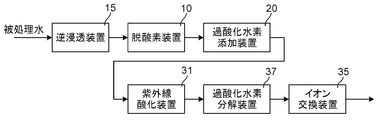
- an ion exchange device 35 to which the outlet water of the ultraviolet oxidation device 31 is supplied is further provided to the water treatment device shown in FIG. 2. The outlet water from the ion exchange device 35 is treated with this water treatment device and is supplied to the outside.
- the organic matter contained in the water to be treated includes substances that are ionic from the stage prior to being subjected to the ultraviolet oxidation treatment, but various organic acids, carbonic acid, etc. are obtained by the ultraviolet oxidation treatment performed by adding H 2 O 2. Ionic substances are produced.
- the ion exchange device 35 removes these ionic substances.
- the ion exchange device 35 is composed of, for example, an ion exchange tower filled with an ion exchange resin. When the concentration of ionic impurities in the outlet water of the ultraviolet oxidizer 31 is high, it is preferable to use a regenerative ion exchanger.
- the ion exchange resin used in the ion exchange device 35 is at least an anion exchange resin. Since organic acids and carbonic acids are weak acids, it is preferable to use a strongly basic anion exchange resin as an anion exchange resin in order to remove them reliably. Furthermore, by using a mixed resin of an anion exchange resin and a cation exchange resin as an ion exchange resin, or using a mixed bed type ion exchange tower filled with a mixed resin as an ion exchange tower, a high-purity treatment is performed. You can get water.
- the water treatment apparatus shown in FIG. 5 includes a hydrogen peroxide decomposition apparatus 37 that decomposes H 2 O 2 in water between the ultraviolet oxidation apparatus 31 and the ion exchange apparatus 35 in the water treatment apparatus shown in FIG. Is. Hydrogen peroxide is removed from the outlet water of the ultraviolet oxidation device 31 through the hydrogen peroxide decomposition device 37, and then supplied to the ion exchange device 35.
- the hydrogen peroxide decomposition device 35 is, for example, a decomposition tower filled with activated carbon. It is preferable to use activated carbon as one that can effectively decompose H 2 O 2 at low cost.
- the hydrogen peroxide decomposition device 37 can decompose H 2 O 2 using a palladium (Pd) catalyst.
- these water treatment apparatuses have a TOC concentration of 0.1 mg / L or more and a dissolved oxygen concentration exceeding 1 mg / L. It can be used for decomposing organic matter in the treated water. According to the present invention, as will become clear from Examples described later, water to be treated containing TOC in the order of mg / L can be treated with a high TOC removal rate. Moreover, in the water treatment apparatus based on this invention, the dissolved oxygen concentration in the exit water of the ultraviolet irradiation device 30 or the ultraviolet oxidation apparatus 31 is 0.1 mg / L or less, for example.
- the water to be treated is derived from, for example, process waste water.
- the water treatment method of the present invention is used to collect and treat process wastewater, particularly wastewater discharged from a process using ultrapure water such as a semiconductor manufacturing process.
- the water treated by the water treatment method of the present invention can be used as raw water for producing ultrapure water. Therefore, the water treatment method of the present invention can be used to collect and treat waste water from the process of using ultrapure water and generate ultrapure water for circulation reuse.
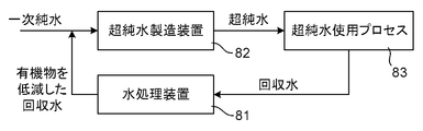
- FIG. 6 shows an application example of the water treatment apparatus according to the present invention.
- the water treatment device 81 according to the present invention uses recovered water collected from the ultrapure water use process 83, which is a process of using ultrapure water, as treated water, and generates recovered water with reduced organic matter by treating this water. .
- the ultrapure water used in the ultrapure water use process 83 is produced by the ultrapure water production apparatus 82 to which the primary pure water is supplied.
- the recovered water from which the organic substances from the water treatment apparatus 81 are reduced is the primary pure water. And supplied to the ultrapure water production apparatus 82.
- the recovery and reuse of ultrapure water is realized through the water treatment device 81, and the primary pure water is consumed by the ultrapure water that was consumed in the ultrapure water use process 83 and could not be recovered. Can be supplied to the ultrapure water production apparatus 82, so that significant water saving can be realized.
- ultrapure water used in the semiconductor manufacturing process for example, a value of 5 ⁇ g / L may be set as the upper limit value of the dissolved oxygen concentration contained therein.
- the recovered water used for the production of ultrapure water generally does not undergo deoxygenation treatment and therefore contains dissolved oxygen.
- the dissolved oxygen concentration in the treated water obtained by this water treatment method can be 0.1 mg / L or less as described above.
- Example 1 An apparatus having the configuration shown in FIG. 7 was assembled.
- isopropyl alcohol (CH 3 CH (OH) CH 3 ; IPA) is added, H 2 O 2 is further added, and IPA is added.
- H 2 O 2 are added to the water.
- the pure water used here had a resistivity of 1 M ⁇ ⁇ cm or more, a TOC of 3 ⁇ g / L or less, a dissolved oxygen concentration of 7.8 mg / L, and a H 2 O 2 concentration of 1 ⁇ g / L or less.
- This device uses pure water containing IPA as an organic substance (TOC component) as water to be treated, and decomposes the organic matter contained in the water to be treated.
- Deoxygenation treatment is performed by membrane deaeration before adding IPA. Can be said to be a treatment for reducing the dissolved oxygen concentration of the water to be treated.
- H 2 O 2 the same result as that obtained when the ultraviolet oxidation treatment is performed after the addition is obtained.
- pure water is supplied to the membrane deaeration module 11 which is a deoxygenation apparatus.
- the membrane degassing module 11 “Lixel G284” manufactured by Celgard was used, and the gas phase side of the membrane degassing module 11 was depressurized by the pump 12, and the degassing treatment was performed so that the dissolved oxygen concentration became a predetermined concentration.
- a predetermined amount of IPA was added as a TOC component through the storage tank 51 and the pump 52 to the water having passed through the membrane degassing module 11 and having a reduced dissolved oxygen concentration. Thereby, the to-be-processed water with which dissolved oxygen concentration was reduced produced
- a predetermined amount of H 2 O 2 was added to the water to be treated via the storage tank 21 and the pump 22.
- a part of the water to be treated to which H 2 O 2 was added was branched, and the dissolved oxygen concentration and the TOC concentration were measured online with a dissolved oxygen meter (DO meter) 56 and a TOC meter 57, respectively.
- DO meter dissolved oxygen meter
- a DO-30A manufactured by TOA Electronics was used as the DO meter 56
- a SIEVERS 900 TOC meter manufactured by Seaverse was used as the TOC meter 57.
- the dissolved oxygen concentration in the DO meter 56 is the dissolved oxygen concentration in the outlet water of the membrane degassing module 11.
- the TOC measurement value TOC0 at the TOC meter 57 is the TOC concentration of the water to be treated.
- the water that was not branched was supplied to the ultraviolet oxidizer 31.
- JPW-2 manufactured by Nippon Photo Science Co., Ltd. is used as the ultraviolet oxidizer 31, and in the ultraviolet oxidizer 31, four low-pressure ultraviolet lamps that generate both light with a wavelength of 254 nm and light with a wavelength of 185 nm are used. Arranged.
- the low-pressure ultraviolet lamp used here is a 165 W ultraviolet lamp AZ-9000W manufactured by Nippon Photoscience.
- a part of the outlet water of the ultraviolet oxidizer 31 is branched and passed through the ion exchange device 35, and the TOC concentration TOC 1 of the outlet water from the ion exchange device 35, that is, the treated water in this water treatment device, is measured. .
- the TOC meter 58 a SIEVERS900 TOC meter manufactured by Seaverse was used.
- the mixed bed type ion exchange apparatus has a cylindrical container made of acrylic resin (inner diameter 25 mm, height 1000 mm), and 300 mL of mixed bed ion exchange resin (EG-5A: manufactured by Organo Corporation) is filled in the container. It is. At this time, the height of the ion exchange resin layer was about 600 mm.
- TOC removal rate (%) ((TOC0 ⁇ TOC1) / TOC0) ⁇ 100
- TOC0 is the TOC concentration of the water to be treated, that is, the TOC concentration measured by the TOC meter 57
- TOC1 is measured by the TOC concentration of the treated water from the ion exchange device 35, that is, the TOC meter 58.
- TOC concentration is the TOC concentration of the treated water from the ion exchange device 35.
- the membrane deaeration module 11 adjusts the dissolved oxygen concentration at the inlet of the ultraviolet oxidizer 31 to 50 ⁇ g / L, and adjusts the amount of IPA added to adjust the TOC concentration of the water to be treated, that is, at the inlet of the ultraviolet oxidizer 31.
- the amount of H 2 O 2 added was 0 mg / L (Comparative Example 1-1), 2.5 mg / L (Example 1-1), 5
- the TOC removal rate was measured in each case after adjusting to 0.0 mg / L (Example 1-2) and 10.0 mg / L (Example 1-3). The results are shown in Table 1.
- the amount of water supplied to the ultraviolet oxidizer 31 was 800 L / hour.
- the TOC removal rate is measured by adjusting the dissolved oxygen concentration to 7.8 mg / L by bypassing the membrane degassing module 11 and setting the amount of H 2 O 2 to be 0 mg / L. (Comparative Example 1-2).
- the results of Comparative Example 1-2 are also shown in Table 1. Since the TOC removal rate in Comparative Example 1-2 was 82%, the concentration of dissolved oxygen in the water to be treated was reduced, and the water to be treated to which H 2 O 2 was added was irradiated with ultraviolet rays. It was found that the TOC removal rate was improved.
- Example 2 Comparative Example 2
- the TOC concentration of water to be treated that is, the TOC concentration at the inlet of the ultraviolet oxidizer 31
- Example 2-1 to 2-3 and Comparative Example 2-1 were designated as Examples 2-1 to 2-3 and Comparative Example 2-1, respectively.
- the results are shown in Table 2. From these results, it was found that the TOC removal rate was improved by reducing the dissolved oxygen concentration in the water to be treated and adding H 2 O 2 .
- the membrane oxygen removal module 11 is bypassed to adjust the dissolved oxygen concentration to 7.8 mg / L, and the amount of H 2 O 2 added is 0 mg / L (Comparative Example 2-2).
- the TOC removal rate was measured as 2.5 mg / L (Comparative Example 2-3). These results are also shown in Table 2.
- the TOC removal rates in Comparative Examples 2-2 and 2-3 were both 71%, and it was found that even when H 2 O 2 was added without reducing the dissolved oxygen concentration, the TOC removal rate in the ultraviolet oxidation treatment was not improved. It was.
- Example 3 Comparative Example 3
- the dissolved oxygen concentration at the inlet of the ultraviolet oxidizer 31 is 500 ⁇ g / L
- the amount of H 2 O 2 added is 0 mg / L (Comparative Example 3-1), 1.5 mg / L (Example 3-1), 2.5 mg.
- the experiment was conducted under the same conditions as in Example 1-1 except that / L (Example 3-2) and 5.0 mg / L (Example 3-3). The results are shown in Table 3.
- Example 4 Comparative Example 4
- the dissolved oxygen concentration at the inlet of the ultraviolet oxidizer 31 is 1000 ⁇ g / L
- the amount of H 2 O 2 added is 0 mg / L (Comparative Example 4-1), 1.5 mg / L (Example 4-1), 2.0 mg.
- the experiment was conducted under the same conditions as in Example 1-1 except that / L (Example 4-2) and 2.5 mg / L (Example 4-3). The results are shown in Table 4.
- the membrane deaeration module 11 adjusts the dissolved oxygen concentration at the inlet of the ultraviolet oxidizer 31 to 50 ⁇ g / L and 1000 ⁇ g / L, and adjusts the amount of IPA added to adjust the TOC concentration of water to be treated, that is, the ultraviolet oxidizer.
- the TOC concentration at the 31 inlet was set to 100 ⁇ g / L.
- the amount of H 2 O 2 added was 0 mg / L (Comparative Example 5-1 and Comparative Example 5-2), 0.2 mg / L (Example 5-1), and 0.05 mg / L (Example). In 5-2), the TOC removal rate was measured in each case.
- the amount of water supplied to the ultraviolet oxidizer 31 was 2000 L / hour. Other than that, the experiment was performed under the same conditions as in Example 1-1. The results are shown in Table 5.
- the membrane oxygen removal module 11 is bypassed to adjust the dissolved oxygen concentration to 7.8 mg / L, and the amount of H 2 O 2 added is 0 mg / L (Comparative Example 5-3). TOC removal rate was measured. These results are also shown in Table 5.
Landscapes
- Water Supply & Treatment (AREA)
- Engineering & Computer Science (AREA)
- Chemical & Material Sciences (AREA)
- Hydrology & Water Resources (AREA)
- Life Sciences & Earth Sciences (AREA)
- Environmental & Geological Engineering (AREA)
- Organic Chemistry (AREA)
- Chemical Kinetics & Catalysis (AREA)
- Nanotechnology (AREA)
- Health & Medical Sciences (AREA)
- Toxicology (AREA)
- Physical Water Treatments (AREA)
- Separation Using Semi-Permeable Membranes (AREA)
- Treatment Of Water By Oxidation Or Reduction (AREA)
Abstract
被処理水に含まれる有機物を分解処理する水処理装置は、有機物の分解効率を向上させて高いTOC(全有機炭素)除去率を達成するために、被処理水の溶存酸素濃度を低減する脱酸素装置と、被処理水に過酸化水素を添加する過酸化水素添加装置と、溶存酸素濃度が低減され過酸化水素が添加された被処理水に対し紫外線を照射する紫外線照射装置と、を備える。
Description
本発明は、処理対象の水である被処理水の中に含まれる有機物を分解処理する水処理方法および装置に関する。
従来より、半導体装置の製造工程や液晶表示装置の製造工程において使用される洗浄水などとして、有機物、イオン成分、微粒子、細菌などが高度に除去された超純水などの純水が使用されている。特に、半導体装置を含む電子部品を製造する際には、その洗浄工程において多量の純水が使用されており、その水質に対する要求も年々高まっている。電子部品製造の洗浄工程などにおいて使用される純水では、純水中に含まれる有機物がその後の熱処理工程において炭化して絶縁不良などを引き起こすことを防止するため、水質管理項目の一つである全有機炭素(TOC;Total Organic Carbon)濃度を極めて低いレベルとすることが求められている。
このような純水水質への高度な要求が顕在化するに伴って、近年、純水中に含まれる微量の有機物(TOC成分)を分解し除去する様々な方法の検討がなされている。そのような方法の代表的なものとして、紫外線酸化処理による有機物の分解除去工程が用いられている。
一般的には、紫外線酸化処理によって有機物の分解除去を行う場合には、例えばステンレス製の反応槽とその反応槽内に設置された管状の紫外線ランプとを備える紫外線酸化装置を用い、反応槽内に被処理水を導入して被処理水に紫外線を照射する。紫外線ランプとしては、例えば、254nmと185nmの各波長を有する紫外線を発生する低圧紫外線ランプが使用される。被処理水に185nmの波長を含む紫外線が照射されると、被処理水内にヒドロキシルラジカル(・OH)などの酸化種が生成し、この酸化種の酸化力により被処理水中の微量有機物が二酸化炭素や有機酸に分解する。被処理水に対してこのように紫外線酸化処理を施して得られた処理水は、次に、後段に配置されているイオン交換装置に送られ、二酸化炭素や有機酸が除去される。
しかしながら、一般的な紫外線酸化装置によるTOCの酸化分解方法では、紫外線ランプを使用するが、紫外線ランプは、非常に高価であるにもかかわらず使用期間の経過とともに紫外線強度が低下するために、例えば1年に1回程度の交換が必要である。したがって、紫外線酸化装置を用いるTOCの酸化分解処理では、紫外線ランプの交換費用の削減およびエネルギー消費量の削減といった、ランニングコストの抑制が課題となっている。
TOCの分解効率を上げるため、例えば特許文献1では、低圧紫外線酸化装置を用いて被処理水中のTOCを除去する水処理装置として、低圧紫外線酸化装置の前段に、被処理水中に酸素ガスを添加する溶存酸素濃度調整工程を設けたものが提案されている。低圧紫外線酸化装置は、低圧紫外線ランプを使用した酸化装置である。また特許文献2では、低圧紫外線酸化装置の前段において被処理水に所定量の過酸化水素(H2O2)を添加することが提案されている。
ところで近年、水資源の枯渇と悪化に対応するため、超純水を多用する半導体工場などにおいても節水が強く要望されている。節水を実現するためには一度使用した水を回収して再利用することが効果的であり、水回収率を上げるため、例えば、ユースポイントで使用した後のTOC濃度の高い排水を処理し、さらには回収して処理するための技術の検討が進められている。このような技術は、一般に、排水処理技術、排水回収処理技術などとも呼ばれる。TOC濃度の高い排水を超純水生成の原水として回収し再利用するためには、エネルギーコストをかけずに、かつ末端の超純水水質を悪化させないレベルまでTOC濃度を低減させることが必要である。TOC濃度が高い被処理水を処理する技術として、被処理水に対して過酸化水素やオゾン(O3)などの酸化剤を添加し、紫外線照射によってTOCを酸化分解する技術がある。この場合、被処理水におけるTOC濃度はmg/Lオーダーであることが想定されており、また、もともと各種の不純物を多く含んでいる被処理水を対象としていることから、例えば開放系の反応容器を使用して紫外線照射を行っている。そして、紫外線源としては、254nmの波長を発生する低圧紫外線ランプもしくは高圧紫外線ランプが一般に使用されている。
被処理水中のTOC成分を分解除去するために、一般に紫外線を照射してTOC成分を酸化させる処理が行われるが、被処理水中のTOCをどれだけ除去できたかという観点で検討すると、これまでの技術は必ずしも最適化されているとは言えない。特に、特許文献2に示されるように過酸化水素を添加した上で紫外線酸化処理を行う場合については、過酸化水素の添加量あるいは濃度以外の要因がTOC除去率に与える影響について、十分な検討がなされてきたとは言えない。そのため、被処理水でのTOC除去率を高めるようとするときに、過度に紫外線照射量を大きくすることとなって、必要電力量が大きくなり、エネルギーコストが上昇し、また装置規模も大きくなるという課題がある。
本発明の目的は、装置の小型化が可能であって、エネルギーコストを含むランニングコストを抑えることができ、有機物の分解効率を向上させることができる水処理方法および装置を提供することにある。
本発明者らは、過酸化水素を添加して紫外線照射を行うことによって被処理水中の有機物の分解処理を行う場合に、被処理水中の溶存酸素濃度がTOC除去率に大きな影響を及ぼすことを見出し、本発明を完成させた。すなわち、本発明の水処理方法は、被処理水の溶存酸素濃度を低減する脱酸素段階と、被処理水に過酸化水素を添加する過酸化水素添加段階と、溶存酸素濃度が低減されかつ過酸化水素が添加された被処理水に対し紫外線を照射する紫外線照射段階と、を有する。
本発明の水処理装置は、被処理水に含まれる有機物を分解処理する水処理装置であって、被処理水の溶存酸素濃度を低減する脱酸素装置と、前記被処理水に過酸化水素を添加する過酸化水素添加装置と、溶存酸素濃度が低減され過酸化水素が添加された被処理水に対し紫外線を照射する紫外線照射装置と、を有する。
本発明によれば、被処理水中の有機物の分解効率が向上して高いTOC除去率を達成することができ、それにより装置の小型化とランニングコストの低減とを実現することができる。
次に、本発明の好ましい実施の形態について、図面を参照して説明する。
図1は、本発明に基づく水処理装置の基本的な構成を示している。図1に示す水処理装置は、被処理水に含まれる有機物を分解処理する水処理装置であり、被処理水が供給されて被処理水の溶存酸素(DO;Dissolved oxygen)濃度を低減する脱酸素装置10と、脱酸素装置10の出口に接続され、被処理水に過酸化水素(H2O2)を添加する過酸化水素添加装置20と、過酸化水素添加装置20の出口に接続され、溶存酸素濃度が低減されて過酸化水素が添加された被処理水に対し紫外線を照射する紫外線照射装置30と、を備えている。紫外線照射装置30としては、185nm以下の波長を含む紫外線を照射して紫外線酸化処理を行う紫外線酸化装置を用いることが好ましい。図1に示す水処理装置では、紫外線照射装置30からの出口水が、この水処理装置によって処理されて外部に供給される水ということになる。
H2O2を添加して紫外線照射処理を行う従来の水処理装置では、紫外線照射処理のための紫外線照射装置として、波長254nmの紫外線を発する殺菌ランプや高圧水銀ランプが一般的に使用されている。また上述した特許文献2に記載されたシステムは、循環精製処理により超純水を製造するシステムであって、波長185nmの成分を含む紫外線を発生する低圧紫外線酸化装置を使用し、被処理水にH2O2を加えて紫外線酸化処理を行うものである。波長185nmの紫外線は一般に低圧水銀ランプによって発生するが、低圧水銀ランプは、同時に波長254nmの紫外線も発生する。その割合は、強度比でおよそ1:9であり、波長254nmの成分の方が強度が大きい。波長185nmの紫外線は低強度ではあるものの有機物を直接分解することができるという利点を有する。一方、波長254nmの紫外線は、H2O2と反応してヒドロキシルラジカル(・OH)を生成することで有機物を分解する。本発明に基づく水処理装置において用いられる紫外線照射装置には、紫外線源として、例えば、波長185nmと波長254nmの両方の紫外線を発生する水銀ランプが用いられるが、それ以外の紫外線源、例えば、紫外線LED(発光ダイオード)を用いることも可能である。
脱酸素装置10としては、水に溶存する酸素(O2)を除去できるものであれば任意のものを用いることができるが、例えば、真空脱気装置、膜脱気装置および窒素脱気装置のいずれかを用いることができる。真空脱気装置、膜脱気装置および窒素脱気装置は、水中の溶存酸素濃度を低減すると同時に揮発性有機物や炭酸などを気相中に除去し、これらの水中の濃度を低減することができる点で好ましい。その他の脱酸素装置として、水素(H2)を添加した上でパラジウム(Pd)触媒によって酸素を水素と反応させて水とすることにより酸素を除去するものを用いることもできる。
水中の溶存酸素濃度は、大気圧下で飽和したときに7~8mg/L程度である。溶存酸素濃度が低い超純水であっても、大気に曝されると直ちに酸素が溶け込み、溶存酸素濃度が上昇する。したがって、一般に、各種の工程から排出される排水中の溶存酸素濃度は1mg/Lを超え、多くの場合、大気圧下での飽和量に近い値となる。本発明者らの知見によれば、溶存酸素濃度が1mg/Lを超えると、H2O2を添加して紫外線酸化処理を行っても、必ずしもTOC除去率の向上が見られない。そこで本発明に基づく水処理装置では、脱酸素装置10の出口水の溶存酸素濃度が1mg/L以下となるようにすることが好ましい。溶存酸素は紫外線を吸収するため、溶存酸素濃度が高い場合には、本来は有機物の分解反応に利用されるはずの紫外線量が減少し、有機物分解が進行しにくくなる。その一方で、溶存酸素をある程度除去することにより、紫外線が吸収されることの影響を少なくすることができる。その結果、紫外線が効率的に有機物と反応してTOC除去率が向上する。また、紫外線とH2O2が効率的に反応し、ヒドロキシルラジカルが生成することで、ヒドロキシルラジカルが有機物と反応してTOC除去率が向上する。したがって、脱酸素装置10の出口水の溶存酸素濃度を1mg/L以下とすることによって、目安としては、大気圧下での飽和量の1/10以下とすることによって、本発明の効果がより顕著に発揮されることとなる。極低濃度、例えばμg/Lまで溶存酸素を低減してもよいが、μg/Lのオーダーまで高度に脱酸素処理を行ったとしても、得られるTOC除去性能に大きな差異は生じない。脱酸素処理に要するコストとTOC除去率とからなる費用対効果を考慮すると、脱酸素装置10の出口水の溶存酸素濃度を0.05mg/L以上1mg/L以下とすることが好ましい。より好ましくは0.05mg/L以上0.5mg/L以下とし、さらに好ましくは0.05mg/L以上0.1mg/Lとする。
図2は、本発明に基づく水処理装置の別の構成例を示している。図1に示した水処理装置は、紫外線酸化処理によって被処理水中のTOC成分を分解しTOCを除去するものであるが、被処理水中のTOC濃度が高い場合には、紫外線酸化処理の負荷が大きくなりすぎるので、紫外線酸化処理を行う前に、具体的にはH2O2を添加する前に、被処理水のTOCを低減することが好ましい。図2に示した水処理装置は、図1に示す水処理装置において、紫外線酸化処理を行う紫外線照射装置30として、波長185nmの成分を含む紫外線を発生する紫外線酸化装置31を使用し、脱酸素装置10の前段に逆浸透装置15を設けたものである。被処理水はまず逆浸透装置15に供給されてそこでTOCが低減され、その後、脱酸素装置10に供給される。その結果、図2に示される水処理装置では、紫外線酸化装置31におけるTOC除去の負荷が軽減される。逆浸透装置15として、逆浸透膜が多段に設置された多段処理装置を用いることが好ましい。多段に設けられた逆浸透膜を用いることにより、さらにTOCを排除して、紫外線酸化処理の負荷を低減することができる。
逆浸透装置15に設けられる逆浸透膜としては、TOC除去能力が高い、例えば海水の淡水化などの用いられるような高阻止率の逆浸透膜を用いることが好ましい。具体的には、有効圧力1MPaあたりの透過流束が0.5m3/m2/d以下であることを特徴するものである。本発明に基づく水処理装置において使用することができる逆浸透膜としては、例えば、Hydranautics社によるSWCシリーズの膜、東レ社によるTM800シリーズの膜、DOW社によるSW30シリーズの膜、栗田工業社によるHR-ROシリーズの膜などが挙げられる。より具体的には、逆浸透膜として、Hydranautics社製のSWC5MAX(0.32m3/m2/d)、Hydranautics社製のSWC6MAX(0.43m3/m2/d)、DOW社製のSW30ULE(0.39m3/m2/d)、DOW社製のSW30HRLE(0.25m3/m2/d)、東レ社製のTM820V(0.32m3/m2/d)、東レ社製のTM820K(0.20m3/m2/d)、栗田工業社製のHR-RO(0.36m3/m2/d)などを用いることができる。ここでかっこ書きにした数値は、その逆浸透膜における有効圧力1MPaあたりの透過流束である。
なお、透過流束は、透過水量を膜面積で割ったものである。「有効圧力」とは、JIS K3802:2015「膜用語」に記載の、平均操作圧から浸透圧差および二次側圧を差し引いた、膜に働く有効な圧である。なお、平均操作圧は、膜の一次側における膜供給水の圧力すなわち運転圧力と濃縮水の圧力すなわち濃縮水出口圧力との平均値であって、以下の式により表される。
平均操作圧=(運転圧力+濃縮水出口圧力)/2
有効圧力1MPaあたりの透過流束は、膜メーカーのカタログに記載の情報、例えば、透過水量、膜面積、評価時の回収率、NaCl濃度などから計算することができる。また、1つまたは複数の圧力容器に同一の透過流束である膜が複数本装填されている場合、圧力容器の平均操作圧/2次側圧力、原水水質、透過水量、膜本数などの情報より、装填された膜の透過流束を計算することができる。
有効圧力1MPaあたりの透過流束は、膜メーカーのカタログに記載の情報、例えば、透過水量、膜面積、評価時の回収率、NaCl濃度などから計算することができる。また、1つまたは複数の圧力容器に同一の透過流束である膜が複数本装填されている場合、圧力容器の平均操作圧/2次側圧力、原水水質、透過水量、膜本数などの情報より、装填された膜の透過流束を計算することができる。
逆浸透膜の膜形状としては、特に限定されるものではなく、例えば、環状型、平膜型、スパイラル型、中空糸型などが挙げられ、スパイラル型については、4インチ型、8インチ型、16インチ型などのいずれでもあってもよい。
図2に示した水処理装置では、脱酸素装置10の前段に逆浸透装置15を設けているが、紫外線酸化処理の負荷を低減するための逆浸透装置15の位置は、過酸化水素添加装置20の入口側であればいずれであってもよい。したがって、図3に示すように、脱酸素装置10と逆浸透装置15の位置を入れ替え、被処理水がまず脱酸素装置10に供給され、脱酸素装置10の出口水が逆浸透装置15を経て過酸化水素添加装置20に供給されるようにしてもよい。
本発明においては、紫外線照射装置の出口側に、紫外線酸化処理での分解生成物や被処理水に由来するイオン性不純物を除去するためのイオン交換装置を設けるようにしてもよい。図4に示す水処理装置では、図2に示す水処理装置に対し、さらに、紫外線酸化装置31の出口水が供給されるイオン交換装置35が設けられている。イオン交換装置35からの出口水が、この水処理装置で処理されて外部に供給される水ということになる。
被処理水に含まれる有機物には、紫外線酸化処理を受ける前の段階からイオン性である物質も含まれるが、H2O2を添加して行う紫外線酸化処理によって、各種の有機酸や炭酸などのイオン性物質が生成する。イオン交換装置35は、これらのイオン性物質を除去する。イオン交換装置35は、例えば、イオン交換樹脂が充填されたイオン交換塔で構成される。紫外線酸化装置31の出口水におけるイオン性不純物の濃度が大きい場合には、再生型のイオン交換装置を用いることが好ましい。紫外線酸化処理による反応生成物である有機酸や炭酸は水中では陰イオンの形態をとるので、イオン交換装置35に用いられるイオン交換樹脂は、少なくとも陰イオン交換樹脂である。有機酸や炭酸は弱酸であるため、これらを確実に除去するために、陰イオン交換樹脂として強塩基性陰イオン交換樹脂を用いることが好ましい。さらに、イオン交換樹脂として、陰イオン交換樹脂と陽イオン交換樹脂との混合樹脂を用いたり、イオン交換塔として、混合樹脂が充填された混床式イオン交換塔を用いることによって、高純度の処理水を得ることができる。
ところで、紫外線酸化装置31の出口水に含まれる過剰なH2O2は、イオン交換装置35内のイオン交換樹脂を酸化劣化させるおそれがある。そのため、イオン交換装置35の前段でH2O2を除去することが好ましい。図5に示す水処理装置は、図4に示す水処理装置において、紫外線酸化装置31とイオン交換装置35との間に、水中のH2O2を分解する過酸化水素分解装置37を設けたものである。紫外線酸化装置31の出口水は、過酸化水素分解装置37を通って過酸化水素が除去され、その後、イオン交換装置35に供給される。過酸化水素分解装置35は、例えば、活性炭が充填された分解塔である。低コストで効果的にH2O2を分解できるものとして、活性炭を用いることが好ましい。あるいは、過酸化水素分解装置37において、パラジウム(Pd)触媒を用いてH2O2を分解するようにすることもできる。
以上、本発明に基づく水処理装置に種々の構成例を説明したが、これらの水処理装置は、例えば、TOC濃度が0.1mg/L以上であり、溶存酸素濃度が1mg/Lを超える被処理水中の有機物を分解処理するために用いることできる。本発明によれば、後述する実施例から明らかになるように、mg/LのオーダーでTOCを含む被処理水を高いTOC除去率で処理することができる。また本発明に基づく水処理装置において、紫外線照射装置30あるいは紫外線酸化装置31の出口水における溶存酸素濃度は、例えば、0.1mg/L以下である。
本発明において被処理水は、例えば、工程排水に由来するものである。本発明の水処理方法は、工程排水、特に半導体製造工程など超純水を使用する工程から排出される排水を回収して処理するために用いられる。本発明の水処理方法によって処理された水は、超純水を生成するための原水として用いることができる。したがって、本発明の水処理方法は、超純水を使用する工程からの排水を回収して処理し、循環再利用のために超純水を生成するために使用することができる。
図6は、本発明に基づく水処理装置の応用例を示している。本発明に基づく水処理装置81は、超純水を使用する工程である超純水使用プロセス83から回収した回収水を被処理水とし、これを処理して有機物を低減した回収水を生成する。超純水使用プロセス83で使用する超純水は、一次純水が供給される超純水製造装置82によって製造されるが、水処理装置81からの有機物を低減した回収水は、一次純水と混合されて超純水製造装置82に供給される。図6に示すシステムでは、水処理装置81を介して超純水の回収再利用が実現しており、超純水使用プロセス83で消費されて回収できなかった超純水の分だけ一次純水を超純水製造装置82に供給すればよいので、大幅な節水を実現することができる。
なお、半導体製造工程に用いられる超純水ではそこに含まれる溶存酸素濃度の上限値として例えば5μg/Lといった値が設定されていることがある。これに対して、超純水の製造に用いられた回収水では、一般に脱酸素処理を行っていないので、溶存酸素が含まれている。本発明の水処理方法では脱酸素処理を行っており、この水処理方法によって得られる処理水での溶存酸素濃度を上述のように0.1mg/L以下とすることができるから、本発明の水処理方法からの処理水を一次純水に混合することによって、全体として、超純水製造における溶存酸素低減のための処理の負荷も低減することができる。
次に、実施例および比較例に基づいて、本発明をさらに詳しく説明する。
[実施例1、比較例1]
図7に示す構成の装置を組み立てた。この装置は、純水に対して膜脱気による脱酸素処理を行ったのちに、イソプロピルアルコール(CH3CH(OH)CH3;IPA)を添加し、さらにH2O2を添加し、IPAとH2O2が添加された水に対して紫外線酸化処理を行うようにしたものである。ここで用いる純水の水質は、抵抗率が1MΩ・cm以上、TOCが3μg/L以下、溶存酸素濃度が7.8mg/L、H2O2濃度が1μg/L以下であった。この装置は、IPAを有機物(TOC成分)として含む純水を被処理水として、この被処理水に含まれる有機物を分解処理する装置であり、IPAを添加する前の膜脱気による脱酸素処理は被処理水の溶存酸素濃度を低減するための処理であると言える。膜脱気によっては水中のIPAは一般に除去されないことを考えれば、図7に示す装置により、IPAを含む被処理水を脱酸素処理に供給して脱酸素処理を行い、その後H2O2を添加して紫外線酸化処理を行う場合と同じ結果が得られることになる。
図7に示す構成の装置を組み立てた。この装置は、純水に対して膜脱気による脱酸素処理を行ったのちに、イソプロピルアルコール(CH3CH(OH)CH3;IPA)を添加し、さらにH2O2を添加し、IPAとH2O2が添加された水に対して紫外線酸化処理を行うようにしたものである。ここで用いる純水の水質は、抵抗率が1MΩ・cm以上、TOCが3μg/L以下、溶存酸素濃度が7.8mg/L、H2O2濃度が1μg/L以下であった。この装置は、IPAを有機物(TOC成分)として含む純水を被処理水として、この被処理水に含まれる有機物を分解処理する装置であり、IPAを添加する前の膜脱気による脱酸素処理は被処理水の溶存酸素濃度を低減するための処理であると言える。膜脱気によっては水中のIPAは一般に除去されないことを考えれば、図7に示す装置により、IPAを含む被処理水を脱酸素処理に供給して脱酸素処理を行い、その後H2O2を添加して紫外線酸化処理を行う場合と同じ結果が得られることになる。
図7に示す装置において、純水は脱酸素装置である膜脱気モジュール11に供給される。膜脱気モジュール11としてはセルガード製「リキセルG284」を用い、膜脱気モジュール11の気相側をポンプ12で減圧にして、溶存酸素濃度が所定濃度となるように脱気処理を施した。膜脱気モジュール11を通過して溶存酸素濃度を低減した水に対し、貯槽51およびポンプ52を介して所定量のIPAをTOC成分として添加した。これにより、溶存酸素濃度が低減された被処理水が生成したことになる。さらにこの被処理水に対し、貯槽21およびポンプ22を介し、所定量のH2O2を添加した。H2O2を添加された被処理水の一部を分岐して、その溶存酸素濃度およびTOC濃度をそれぞれ溶存酸素計(DO計)56およびTOC計57でオンライン測定した。DO計56としてはTOAエレクトロニクス社製DO-30Aを用い、TOC計57としてはシーバース社製のSIEVERS900型TOC計を用いた。DO計56での溶存酸素濃度は、膜脱気モジュール11の出口水における溶存酸素濃度となる。TOC計57でのTOC測定値TOC0は、被処理水のTOC濃度となる。
H2O2が添加された被処理水のうち分岐しなかった方の水を紫外線酸化装置31に供給した。紫外線酸化装置31としては日本フォトサイエンス社製JPW-2を使用し、紫外線酸化装置31内には、紫外線ランプとして、波長254nmの光と波長185nmの光の両方を発生する低圧紫外線ランプを4本配置した。ここで使用した低圧紫外線ランプは、日本フォトサイエンス社製の165Wの紫外線ランプAZ-9000Wである。紫外線酸化装置31の出口水の一部を分岐し、イオン交換装置35に通水し、イオン交換装置35からの出口水すなわちこの水処理装置における処理水のTOC濃度TOC1をTOC計58によって測定した。TOC計58としては、シーバース社製のSIEVERS900型TOC計を用いた。
イオン交換装置35としては、混床式イオン交換装置を用いた。混床式イオン交換装置は、アクリル樹脂製の円筒容器(内径25mm、高さ1000mm)を有し、この容器内に混床のイオン交換樹脂(EG-5A:オルガノ社製)を300mL充填したものである。このとき、イオン交換樹脂層の高さは約600mmとなった。
この水処理装置におけるTOC除去率を以下の計算式により定義する:
TOC除去率(%)=((TOC0-TOC1)/TOC0)×100
上述のように、TOC0は、被処理水のTOC濃度、すなわちTOC計57で測定されたTOC濃度であり、TOC1は、イオン交換装置35からの処理水のTOC濃度、すなわちTOC計58によって測定されたTOC濃度である。
TOC除去率(%)=((TOC0-TOC1)/TOC0)×100
上述のように、TOC0は、被処理水のTOC濃度、すなわちTOC計57で測定されたTOC濃度であり、TOC1は、イオン交換装置35からの処理水のTOC濃度、すなわちTOC計58によって測定されたTOC濃度である。
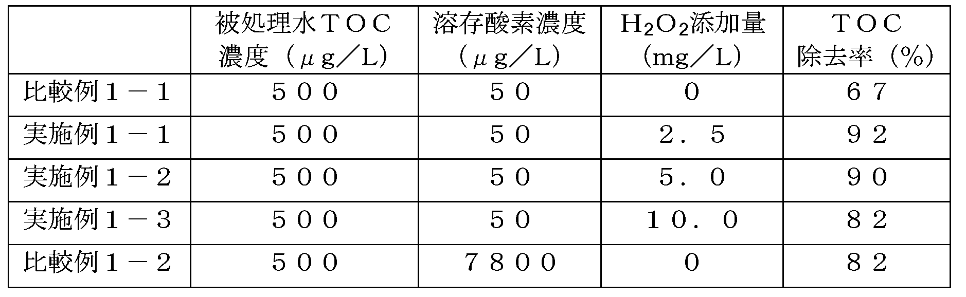
膜脱気モジュール11によって紫外線酸化装置31の入口の溶存酸素濃度を50μg/Lとなるように調整し、IPAの添加量を調整して被処理水のTOC濃度、すなわち紫外線酸化装置31の入口でのTOC濃度が500μg/Lであるようにした、この状態で、H2O2の添加量を0mg/L(比較例1-1)、2.5mg/L(実施例1-1)、5.0mg/L(実施例1-2)、10.0mg/L(実施例1-3)に調整して、それぞれの場合についてTOC除去率を測定した。結果を表1に示す。なお紫外線酸化装置31への供給水量は800L/時間であった。
実施例1-1~1-3と比較例1-1とから、H2O2を添加することでTOC除去率が向上する結果が得られた。
またこれとは別に、膜脱気モジュール11をバイパスすることにより溶存酸素濃度が7.8mg/Lとなるように調整し、H2O2の添加量を0mg/Lとして、TOC除去率を測定した(比較例1-2)。比較例1-2の結果も表1に示す。比較例1-2でのTOC除去率が82%であったことから、被処理水中の溶存酸素濃度を低減し、かつH2O2が添加された被処理水に紫外線を照射することで、TOC除去率が向上することが分かった。
[実施例2、比較例2]
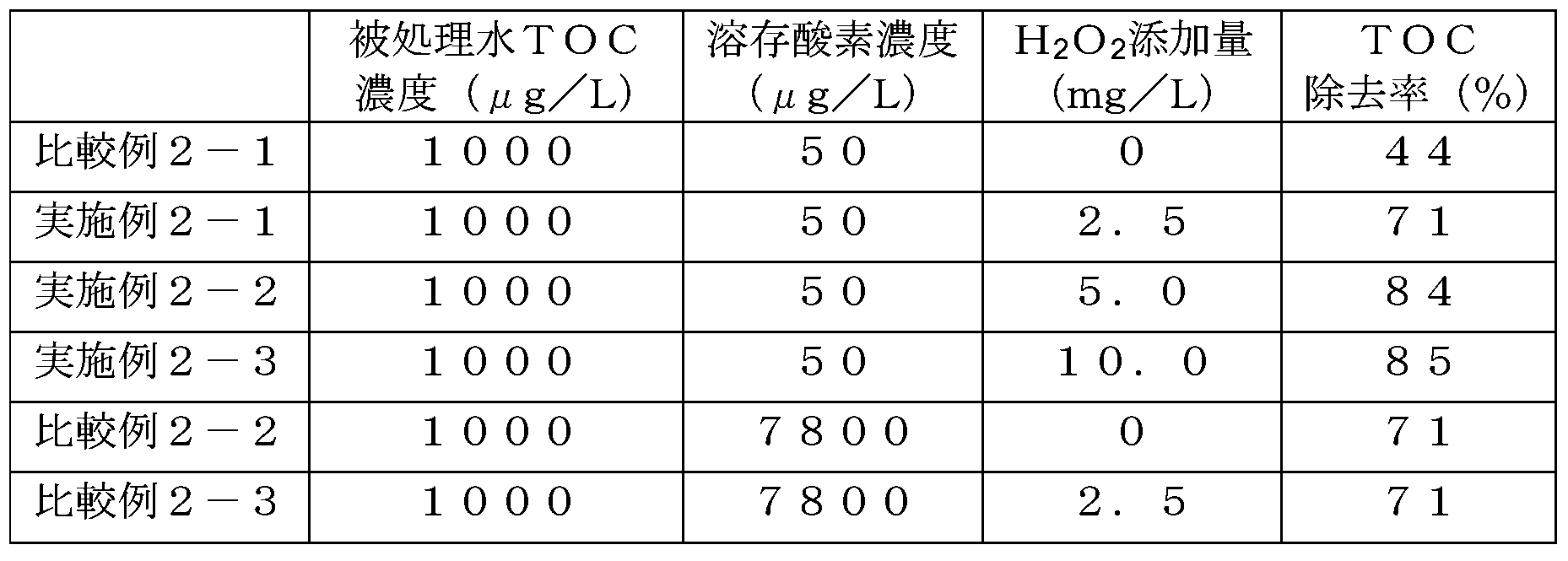
被処理水のTOC濃度、すなわち紫外線酸化装置31の入口でのTOC濃度を1000μg/Lとしたこと以外は実施例1-1~1-3、比較例1-1と同条件で実験を行い、これらをそれぞれ実施例2-1~2-3、比較例2-1とした。結果を表2に示す。これらからも、被処理水中の溶存酸素濃度を低減し、H2O2を添加することでTOC除去率が向上する結果が得られた。
被処理水のTOC濃度、すなわち紫外線酸化装置31の入口でのTOC濃度を1000μg/Lとしたこと以外は実施例1-1~1-3、比較例1-1と同条件で実験を行い、これらをそれぞれ実施例2-1~2-3、比較例2-1とした。結果を表2に示す。これらからも、被処理水中の溶存酸素濃度を低減し、H2O2を添加することでTOC除去率が向上する結果が得られた。
またこれとは別に、膜脱気モジュール11をバイパスすることにより溶存酸素濃度が7.8mg/Lとなるように調整し、H2O2の添加量を0mg/L(比較例2-2)、2.5mg/L(比較例2-3)として、TOC除去率を測定した。これらの結果も表2に示す。比較例2-2,2-3におけるTOC除去率はいずれも71%であり、溶存酸素濃度を低減させないでH2O2を添加しても紫外線酸化処理におけるTOC除去率が向上しないことが分かった。
[実施例3、比較例3]
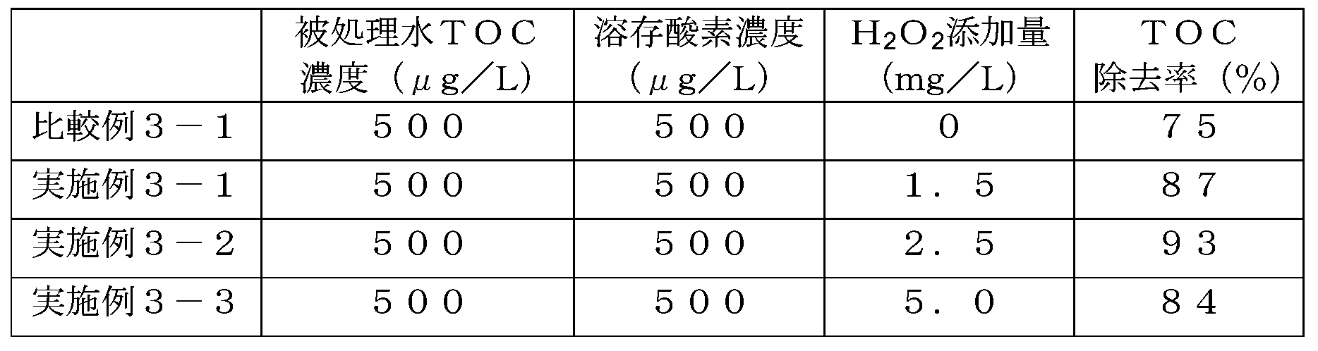
紫外線酸化装置31の入口での溶存酸素濃度を500μg/L、H2O2添加量を0mg/L(比較例3-1)、1.5mg/L(実施例3-1)、2.5mg/L(実施例3-2)、5.0mg/L(実施例3-3)とした以外は、実施例1-1と同様の条件で実験を行った。結果を表3に示す。
紫外線酸化装置31の入口での溶存酸素濃度を500μg/L、H2O2添加量を0mg/L(比較例3-1)、1.5mg/L(実施例3-1)、2.5mg/L(実施例3-2)、5.0mg/L(実施例3-3)とした以外は、実施例1-1と同様の条件で実験を行った。結果を表3に示す。
[実施例4、比較例4]
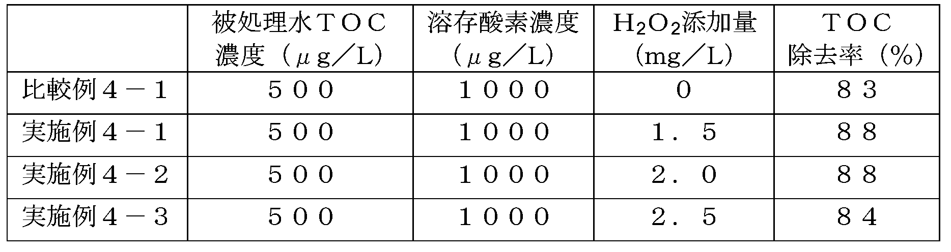
紫外線酸化装置31の入口での溶存酸素濃度を1000μg/L、H2O2添加量を0mg/L(比較例4-1)、1.5mg/L(実施例4-1)、2.0mg/L(実施例4-2)、2.5mg/L(実施例4-3)とした以外は、実施例1-1と同様の条件で実験を行った。結果を表4に示す。
紫外線酸化装置31の入口での溶存酸素濃度を1000μg/L、H2O2添加量を0mg/L(比較例4-1)、1.5mg/L(実施例4-1)、2.0mg/L(実施例4-2)、2.5mg/L(実施例4-3)とした以外は、実施例1-1と同様の条件で実験を行った。結果を表4に示す。
[実施例5、比較例5]
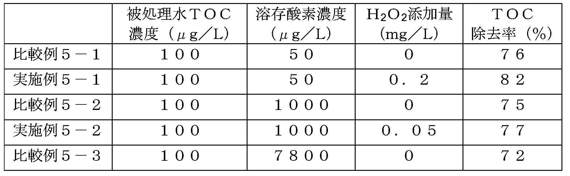
膜脱気モジュール11によって紫外線酸化装置31の入口の溶存酸素濃度を50μg/Lおよび1000μg/Lとなるように調整し、IPAの添加量を調整して被処理水のTOC濃度、すなわち紫外線酸化装置31の入口でのTOC濃度が100μg/Lとなるようにした。この状態で、H2O2の添加量を0mg/L(比較例5-1、比較例5-2)、0.2mg/L(実施例5-1)、0.05mg/L(実施例5-2)に調整して、それぞれの場合についてTOC除去率を測定した。紫外線酸化装置31への供給水量は2000L/時間であった。なおそれ以外については実施例1-1と同様の条件で実験を行った。結果を表5に示す。
膜脱気モジュール11によって紫外線酸化装置31の入口の溶存酸素濃度を50μg/Lおよび1000μg/Lとなるように調整し、IPAの添加量を調整して被処理水のTOC濃度、すなわち紫外線酸化装置31の入口でのTOC濃度が100μg/Lとなるようにした。この状態で、H2O2の添加量を0mg/L(比較例5-1、比較例5-2)、0.2mg/L(実施例5-1)、0.05mg/L(実施例5-2)に調整して、それぞれの場合についてTOC除去率を測定した。紫外線酸化装置31への供給水量は2000L/時間であった。なおそれ以外については実施例1-1と同様の条件で実験を行った。結果を表5に示す。
またこれとは別に、膜脱気モジュール11をバイパスすることにより溶存酸素濃度が7.8mg/Lとなるように調整し、H2O2の添加量を0mg/L(比較例5-3)としてTOC除去率を測定した。これらの結果も表5に示す。
10 脱酸素装置
15 逆浸透装置
20 過酸化水素添加装置
30 紫外線照射装置
31 紫外線酸化装置
15 逆浸透装置
20 過酸化水素添加装置
30 紫外線照射装置
31 紫外線酸化装置
Claims (14)
- 被処理水に含まれる有機物を分解処理する水処理方法であって、
前記被処理水の溶存酸素濃度を低減する脱酸素段階と、
前記被処理水に過酸化水素を添加する過酸化水素添加段階と、
溶存酸素濃度が低減されかつ過酸化水素が添加された被処理水に対し紫外線を照射する紫外線照射段階と、
を有する水処理方法。 - 前記紫外線照射段階において、185nm以下の波長を含む紫外線を照射する、請求項1に記載の水処理方法。
- 前記過酸化水素添加段階の前に、前記被処理水に含まれる有機物を逆浸透処理によって低減する段階をさらに有する、請求項1または2に記載の水処理方法。
- 前記逆浸透処理で用いる逆浸透膜は、有効圧力1MPaあたりの透過流束が0.5m3/m2/d以下である、請求項3に記載の水処理方法。
- 前記水処理方法による処理が行われる前の前記被処理水は、全有機炭素濃度が0.1mg/L以上であり、溶存酸素濃度が1mg/Lを超える、請求項1乃至4のいずれか1項に記載の水処理方法。
- 前記脱酸素段階の出口水の溶存酸素濃度が1mg/L以下である請求項1乃至5のいずれか1項に記載の水処理方法。
- 前記被処理水が工程排水に由来する、請求項1乃至6のいずれか1項に記載の水処理方法。
- 前記工程排水は超純水を使用する工程からの排出される水であり、前記水処理方法により処理された水が、前記工程で使用する超純水を生成するための原水として用いられる、請求項7に記載の水処理方法。
- 被処理水に含まれる有機物を分解処理する水処理装置であって、
前記被処理水の溶存酸素濃度を低減する脱酸素装置と、
前記被処理水に過酸化水素を添加する過酸化水素添加装置と、
溶存酸素濃度が低減され過酸化水素が添加された前記被処理水に対し紫外線を照射する紫外線照射装置と、
を有する水処理装置。 - 前記紫外線照射装置は、185nm以下の波長を含む紫外線を照射する紫外線酸化装置である、請求項9に記載の水処理装置。
- 逆浸透膜を有し前記被処理水に含まれる有機物を低減する逆浸透装置を前記過酸化水素添加装置の入口側に備える、請求項9または10に記載の水処理装置。
- 前記逆浸透膜は、有効圧力1MPaあたりの透過流束が0.5m3/m2/d以下である、請求項11に記載の水処理装置。
- 前記水処理装置に供給される前記被処理水は、全有機炭素濃度が0.1mg/L以上であり、溶存酸素濃度が1mg/Lを超える請求項9乃至12のいずれか1項に記載の水処理装置。
- 前記脱酸素装置の出口水の溶存酸素濃度が1mg/L以下である請求項9乃至13のいずれか1項に記載の水処理装置。
Priority Applications (2)
| Application Number | Priority Date | Filing Date | Title |
|---|---|---|---|
| CN201780067197.2A CN109890766B (zh) | 2016-11-18 | 2017-11-16 | 水处理方法及装置 |
| KR1020197014171A KR102248156B1 (ko) | 2016-11-18 | 2017-11-16 | 수처리 방법 및 장치 |
Applications Claiming Priority (2)
| Application Number | Priority Date | Filing Date | Title |
|---|---|---|---|
| JP2016-224968 | 2016-11-18 | ||
| JP2016224968A JP6752692B2 (ja) | 2016-11-18 | 2016-11-18 | 水処理方法および装置 |
Publications (1)
| Publication Number | Publication Date |
|---|---|
| WO2018092831A1 true WO2018092831A1 (ja) | 2018-05-24 |
Family
ID=62145504
Family Applications (1)
| Application Number | Title | Priority Date | Filing Date |
|---|---|---|---|
| PCT/JP2017/041214 Ceased WO2018092831A1 (ja) | 2016-11-18 | 2017-11-16 | 水処理方法および装置 |
Country Status (5)
| Country | Link |
|---|---|
| JP (1) | JP6752692B2 (ja) |
| KR (1) | KR102248156B1 (ja) |
| CN (1) | CN109890766B (ja) |
| TW (1) | TWI732969B (ja) |
| WO (1) | WO2018092831A1 (ja) |
Cited By (3)
| Publication number | Priority date | Publication date | Assignee | Title |
|---|---|---|---|---|
| CN111454851A (zh) * | 2020-03-20 | 2020-07-28 | 苏州禾优泰源农业科技有限公司 | 一种微生物有氧发酵系统 |
| NO20200773A1 (en) * | 2020-07-01 | 2022-01-03 | Niva Norwegian Institute For Water Res | Method of neutralizing hydrogen peroxide in wastewater from aquaculture delousing treatment |
| WO2022239483A1 (ja) * | 2021-05-14 | 2022-11-17 | 栗田工業株式会社 | 超純水製造方法及び装置 |
Families Citing this family (5)
| Publication number | Priority date | Publication date | Assignee | Title |
|---|---|---|---|---|
| JP7183208B2 (ja) * | 2020-02-14 | 2022-12-05 | 栗田工業株式会社 | 超純水製造装置及び超純水製造方法 |
| JP7368310B2 (ja) * | 2020-05-20 | 2023-10-24 | オルガノ株式会社 | ホウ素除去装置及びホウ素除去方法、並びに、純水製造装置及び純水の製造方法 |
| JP7724067B2 (ja) | 2021-03-10 | 2025-08-15 | オルガノ株式会社 | 水処理方法及び装置 |
| JP7741652B2 (ja) * | 2021-06-17 | 2025-09-18 | オルガノ株式会社 | 純水製造装置及び純水製造方法 |
| KR102553948B1 (ko) | 2023-02-14 | 2023-07-10 | 김기수 | Toc저감 수처리장치 |
Citations (6)
| Publication number | Priority date | Publication date | Assignee | Title |
|---|---|---|---|---|
| JPH10174804A (ja) * | 1996-12-19 | 1998-06-30 | Nomura Micro Sci Co Ltd | 超純水製造装置 |
| JPH11226569A (ja) * | 1998-02-12 | 1999-08-24 | Japan Organo Co Ltd | 水中の有機物除去装置及び超純水製造装置 |
| JPH11244853A (ja) * | 1998-03-06 | 1999-09-14 | Kurita Water Ind Ltd | 純水の製造方法 |
| JP2003266097A (ja) * | 2002-03-13 | 2003-09-24 | Kurita Water Ind Ltd | 超純水製造装置 |
| JP2014168743A (ja) * | 2013-03-04 | 2014-09-18 | Nomura Micro Sci Co Ltd | 純水製造方法 |
| JP2016117001A (ja) * | 2014-12-19 | 2016-06-30 | 栗田工業株式会社 | 超純水製造装置及び超純水製造方法 |
Family Cites Families (10)
| Publication number | Priority date | Publication date | Assignee | Title |
|---|---|---|---|---|
| JPH05305297A (ja) | 1992-04-30 | 1993-11-19 | Kurita Water Ind Ltd | 有機物含有酸性排水の処理装置 |
| JP3645007B2 (ja) * | 1995-07-25 | 2005-05-11 | 野村マイクロ・サイエンス株式会社 | 超純水製造装置 |
| JP3732903B2 (ja) * | 1996-09-11 | 2006-01-11 | オルガノ株式会社 | 超純水製造装置 |
| JP5124946B2 (ja) * | 2006-01-12 | 2013-01-23 | 栗田工業株式会社 | 超純水製造装置における超純水中の過酸化水素の除去方法 |
| TW200829520A (en) * | 2007-01-08 | 2008-07-16 | Advanced Retec Internat Co Ltd | Wastewater recycling system and method of semiconductor process tail gas treatment equipment |
| WO2009082008A1 (ja) * | 2007-12-26 | 2009-07-02 | Organo Corporation | 過酸化水素除去方法およびその装置、オゾン水製造方法およびその装置、並びに洗浄方法およびその装置 |
| CN101983175A (zh) * | 2008-03-31 | 2011-03-02 | 栗田工业株式会社 | 纯水制造方法及纯水制造装置 |
| CN101423310A (zh) * | 2008-11-14 | 2009-05-06 | 钱志刚 | 电子超纯水的循环回用处理方法 |
| JP5499753B2 (ja) | 2010-02-18 | 2014-05-21 | 栗田工業株式会社 | 水処理方法及び装置 |
| JP5512357B2 (ja) | 2010-04-05 | 2014-06-04 | オルガノ株式会社 | 純水製造方法及び装置 |
-
2016
- 2016-11-18 JP JP2016224968A patent/JP6752692B2/ja active Active
-
2017
- 2017-11-14 TW TW106139243A patent/TWI732969B/zh active
- 2017-11-16 WO PCT/JP2017/041214 patent/WO2018092831A1/ja not_active Ceased
- 2017-11-16 KR KR1020197014171A patent/KR102248156B1/ko not_active Expired - Fee Related
- 2017-11-16 CN CN201780067197.2A patent/CN109890766B/zh active Active
Patent Citations (6)
| Publication number | Priority date | Publication date | Assignee | Title |
|---|---|---|---|---|
| JPH10174804A (ja) * | 1996-12-19 | 1998-06-30 | Nomura Micro Sci Co Ltd | 超純水製造装置 |
| JPH11226569A (ja) * | 1998-02-12 | 1999-08-24 | Japan Organo Co Ltd | 水中の有機物除去装置及び超純水製造装置 |
| JPH11244853A (ja) * | 1998-03-06 | 1999-09-14 | Kurita Water Ind Ltd | 純水の製造方法 |
| JP2003266097A (ja) * | 2002-03-13 | 2003-09-24 | Kurita Water Ind Ltd | 超純水製造装置 |
| JP2014168743A (ja) * | 2013-03-04 | 2014-09-18 | Nomura Micro Sci Co Ltd | 純水製造方法 |
| JP2016117001A (ja) * | 2014-12-19 | 2016-06-30 | 栗田工業株式会社 | 超純水製造装置及び超純水製造方法 |
Cited By (5)
| Publication number | Priority date | Publication date | Assignee | Title |
|---|---|---|---|---|
| CN111454851A (zh) * | 2020-03-20 | 2020-07-28 | 苏州禾优泰源农业科技有限公司 | 一种微生物有氧发酵系统 |
| NO20200773A1 (en) * | 2020-07-01 | 2022-01-03 | Niva Norwegian Institute For Water Res | Method of neutralizing hydrogen peroxide in wastewater from aquaculture delousing treatment |
| NO346187B1 (en) * | 2020-07-01 | 2022-04-11 | Niva Norwegian Institute For Water Res | Method of neutralizing hydrogen peroxide in wastewater from aquaculture delousing treatment |
| WO2022239483A1 (ja) * | 2021-05-14 | 2022-11-17 | 栗田工業株式会社 | 超純水製造方法及び装置 |
| JP2022175837A (ja) * | 2021-05-14 | 2022-11-25 | 栗田工業株式会社 | 超純水製造方法及び装置 |
Also Published As
| Publication number | Publication date |
|---|---|
| KR102248156B1 (ko) | 2021-05-04 |
| CN109890766B (zh) | 2023-04-04 |
| JP6752692B2 (ja) | 2020-09-09 |
| JP2018079447A (ja) | 2018-05-24 |
| CN109890766A (zh) | 2019-06-14 |
| TWI732969B (zh) | 2021-07-11 |
| KR20190066055A (ko) | 2019-06-12 |
| TW201829321A (zh) | 2018-08-16 |
Similar Documents
| Publication | Publication Date | Title |
|---|---|---|
| JP6752693B2 (ja) | 水処理方法および装置 | |
| KR102248156B1 (ko) | 수처리 방법 및 장치 | |
| US10550020B2 (en) | Ultraviolet light activated oxidation process for the reduction of organic carbon in semiconductor process water | |
| TWI460136B (zh) | 用於減少半導體製程用水之有機碳的紫外光活化氧化法 | |
| JP5649520B2 (ja) | 超純水製造装置 | |
| JP7289206B2 (ja) | ホウ素除去装置及びホウ素除去方法、並びに、純水製造装置及び純水の製造方法 | |
| JP2015073923A (ja) | 超純水製造方法及び超純水製造システム | |
| JP5512358B2 (ja) | 純水製造方法及び装置 | |
| US20240246834A1 (en) | Pure water production apparatus and pure water production method | |
| JPH1199394A (ja) | 水中の有機物除去方法 | |
| JP4519930B2 (ja) | 超純水製造方法及び超純水製造装置 | |
| JP5678436B2 (ja) | 超純水製造方法及び装置 | |
| JP2000061459A (ja) | 低濃度有機性廃水の処理装置 | |
| JPH05305297A (ja) | 有機物含有酸性排水の処理装置 | |
| JPH1128482A (ja) | 純水製造方法 | |
| JPH0639366A (ja) | 超純水製造方法、及びその装置 | |
| US12577132B2 (en) | Ultrapure water production system and ultrapure water production method | |
| JPH09253639A (ja) | 超純水製造装置 | |
| US12103874B2 (en) | Ultraviolet light activated oxidation process for the reduction of organic carbon in semiconductor process water | |
| JP2005161138A (ja) | 水処理方法および水処理装置 | |
| JP2024109481A (ja) | 水処理方法、水処理装置及び純水製造システム | |
| JPH10174804A (ja) | 超純水製造装置 | |
| JP2019107631A (ja) | 紫外線酸化処理方法 |
Legal Events
| Date | Code | Title | Description |
|---|---|---|---|
| 121 | Ep: the epo has been informed by wipo that ep was designated in this application |
Ref document number: 17871535 Country of ref document: EP Kind code of ref document: A1 |
|
| ENP | Entry into the national phase |
Ref document number: 20197014171 Country of ref document: KR Kind code of ref document: A |
|
| NENP | Non-entry into the national phase |
Ref country code: DE |
|
| 122 | Ep: pct application non-entry in european phase |
Ref document number: 17871535 Country of ref document: EP Kind code of ref document: A1 |