WO2018092562A1 - Dispositif de surveillance de batterie de véhicule et système de surveillance de batterie de véhicule - Google Patents
Dispositif de surveillance de batterie de véhicule et système de surveillance de batterie de véhicule Download PDFInfo
- Publication number
- WO2018092562A1 WO2018092562A1 PCT/JP2017/039068 JP2017039068W WO2018092562A1 WO 2018092562 A1 WO2018092562 A1 WO 2018092562A1 JP 2017039068 W JP2017039068 W JP 2017039068W WO 2018092562 A1 WO2018092562 A1 WO 2018092562A1
- Authority
- WO
- WIPO (PCT)
- Prior art keywords
- battery
- monitoring device
- battery monitoring
- command
- wireless transmission
- Prior art date
Links
Images


Classifications
-
- G—PHYSICS
- G01—MEASURING; TESTING
- G01R—MEASURING ELECTRIC VARIABLES; MEASURING MAGNETIC VARIABLES
- G01R31/00—Arrangements for testing electric properties; Arrangements for locating electric faults; Arrangements for electrical testing characterised by what is being tested not provided for elsewhere
- G01R31/36—Arrangements for testing, measuring or monitoring the electrical condition of accumulators or electric batteries, e.g. capacity or state of charge [SoC]
- G01R31/382—Arrangements for monitoring battery or accumulator variables, e.g. SoC
- G01R31/3835—Arrangements for monitoring battery or accumulator variables, e.g. SoC involving only voltage measurements
-
- G—PHYSICS
- G01—MEASURING; TESTING
- G01R—MEASURING ELECTRIC VARIABLES; MEASURING MAGNETIC VARIABLES
- G01R31/00—Arrangements for testing electric properties; Arrangements for locating electric faults; Arrangements for electrical testing characterised by what is being tested not provided for elsewhere
- G01R31/36—Arrangements for testing, measuring or monitoring the electrical condition of accumulators or electric batteries, e.g. capacity or state of charge [SoC]
- G01R31/371—Arrangements for testing, measuring or monitoring the electrical condition of accumulators or electric batteries, e.g. capacity or state of charge [SoC] with remote indication, e.g. on external chargers
-
- H—ELECTRICITY
- H01—ELECTRIC ELEMENTS
- H01M—PROCESSES OR MEANS, e.g. BATTERIES, FOR THE DIRECT CONVERSION OF CHEMICAL ENERGY INTO ELECTRICAL ENERGY
- H01M10/00—Secondary cells; Manufacture thereof
- H01M10/42—Methods or arrangements for servicing or maintenance of secondary cells or secondary half-cells
- H01M10/425—Structural combination with electronic components, e.g. electronic circuits integrated to the outside of the casing
-
- H—ELECTRICITY
- H01—ELECTRIC ELEMENTS
- H01M—PROCESSES OR MEANS, e.g. BATTERIES, FOR THE DIRECT CONVERSION OF CHEMICAL ENERGY INTO ELECTRICAL ENERGY
- H01M10/00—Secondary cells; Manufacture thereof
- H01M10/42—Methods or arrangements for servicing or maintenance of secondary cells or secondary half-cells
- H01M10/44—Methods for charging or discharging
-
- H—ELECTRICITY
- H01—ELECTRIC ELEMENTS
- H01M—PROCESSES OR MEANS, e.g. BATTERIES, FOR THE DIRECT CONVERSION OF CHEMICAL ENERGY INTO ELECTRICAL ENERGY
- H01M10/00—Secondary cells; Manufacture thereof
- H01M10/42—Methods or arrangements for servicing or maintenance of secondary cells or secondary half-cells
- H01M10/48—Accumulators combined with arrangements for measuring, testing or indicating the condition of cells, e.g. the level or density of the electrolyte
- H01M10/486—Accumulators combined with arrangements for measuring, testing or indicating the condition of cells, e.g. the level or density of the electrolyte for measuring temperature
-
- H—ELECTRICITY
- H02—GENERATION; CONVERSION OR DISTRIBUTION OF ELECTRIC POWER
- H02J—CIRCUIT ARRANGEMENTS OR SYSTEMS FOR SUPPLYING OR DISTRIBUTING ELECTRIC POWER; SYSTEMS FOR STORING ELECTRIC ENERGY
- H02J7/00—Circuit arrangements for charging or depolarising batteries or for supplying loads from batteries
- H02J7/0013—Circuit arrangements for charging or depolarising batteries or for supplying loads from batteries acting upon several batteries simultaneously or sequentially
- H02J7/0014—Circuits for equalisation of charge between batteries
- H02J7/0016—Circuits for equalisation of charge between batteries using shunting, discharge or bypass circuits
-
- H—ELECTRICITY
- H02—GENERATION; CONVERSION OR DISTRIBUTION OF ELECTRIC POWER
- H02J—CIRCUIT ARRANGEMENTS OR SYSTEMS FOR SUPPLYING OR DISTRIBUTING ELECTRIC POWER; SYSTEMS FOR STORING ELECTRIC ENERGY
- H02J7/00—Circuit arrangements for charging or depolarising batteries or for supplying loads from batteries
- H02J7/0047—Circuit arrangements for charging or depolarising batteries or for supplying loads from batteries with monitoring or indicating devices or circuits
-
- H—ELECTRICITY
- H04—ELECTRIC COMMUNICATION TECHNIQUE
- H04W—WIRELESS COMMUNICATION NETWORKS
- H04W4/00—Services specially adapted for wireless communication networks; Facilities therefor
- H04W4/30—Services specially adapted for particular environments, situations or purposes
- H04W4/38—Services specially adapted for particular environments, situations or purposes for collecting sensor information
-
- G—PHYSICS
- G01—MEASURING; TESTING
- G01R—MEASURING ELECTRIC VARIABLES; MEASURING MAGNETIC VARIABLES
- G01R31/00—Arrangements for testing electric properties; Arrangements for locating electric faults; Arrangements for electrical testing characterised by what is being tested not provided for elsewhere
- G01R31/36—Arrangements for testing, measuring or monitoring the electrical condition of accumulators or electric batteries, e.g. capacity or state of charge [SoC]
- G01R31/374—Arrangements for testing, measuring or monitoring the electrical condition of accumulators or electric batteries, e.g. capacity or state of charge [SoC] with means for correcting the measurement for temperature or ageing
-
- G—PHYSICS
- G01—MEASURING; TESTING
- G01R—MEASURING ELECTRIC VARIABLES; MEASURING MAGNETIC VARIABLES
- G01R31/00—Arrangements for testing electric properties; Arrangements for locating electric faults; Arrangements for electrical testing characterised by what is being tested not provided for elsewhere
- G01R31/36—Arrangements for testing, measuring or monitoring the electrical condition of accumulators or electric batteries, e.g. capacity or state of charge [SoC]
- G01R31/396—Acquisition or processing of data for testing or for monitoring individual cells or groups of cells within a battery
-
- H—ELECTRICITY
- H01—ELECTRIC ELEMENTS
- H01M—PROCESSES OR MEANS, e.g. BATTERIES, FOR THE DIRECT CONVERSION OF CHEMICAL ENERGY INTO ELECTRICAL ENERGY
- H01M10/00—Secondary cells; Manufacture thereof
- H01M10/42—Methods or arrangements for servicing or maintenance of secondary cells or secondary half-cells
- H01M10/425—Structural combination with electronic components, e.g. electronic circuits integrated to the outside of the casing
- H01M2010/4271—Battery management systems including electronic circuits, e.g. control of current or voltage to keep battery in healthy state, cell balancing
-
- H—ELECTRICITY
- H01—ELECTRIC ELEMENTS
- H01M—PROCESSES OR MEANS, e.g. BATTERIES, FOR THE DIRECT CONVERSION OF CHEMICAL ENERGY INTO ELECTRICAL ENERGY
- H01M10/00—Secondary cells; Manufacture thereof
- H01M10/42—Methods or arrangements for servicing or maintenance of secondary cells or secondary half-cells
- H01M10/425—Structural combination with electronic components, e.g. electronic circuits integrated to the outside of the casing
- H01M2010/4278—Systems for data transfer from batteries, e.g. transfer of battery parameters to a controller, data transferred between battery controller and main controller
-
- H—ELECTRICITY
- H01—ELECTRIC ELEMENTS
- H01M—PROCESSES OR MEANS, e.g. BATTERIES, FOR THE DIRECT CONVERSION OF CHEMICAL ENERGY INTO ELECTRICAL ENERGY
- H01M2220/00—Batteries for particular applications
- H01M2220/20—Batteries in motive systems, e.g. vehicle, ship, plane
-
- Y—GENERAL TAGGING OF NEW TECHNOLOGICAL DEVELOPMENTS; GENERAL TAGGING OF CROSS-SECTIONAL TECHNOLOGIES SPANNING OVER SEVERAL SECTIONS OF THE IPC; TECHNICAL SUBJECTS COVERED BY FORMER USPC CROSS-REFERENCE ART COLLECTIONS [XRACs] AND DIGESTS
- Y02—TECHNOLOGIES OR APPLICATIONS FOR MITIGATION OR ADAPTATION AGAINST CLIMATE CHANGE
- Y02E—REDUCTION OF GREENHOUSE GAS [GHG] EMISSIONS, RELATED TO ENERGY GENERATION, TRANSMISSION OR DISTRIBUTION
- Y02E60/00—Enabling technologies; Technologies with a potential or indirect contribution to GHG emissions mitigation
- Y02E60/10—Energy storage using batteries
Definitions
- the present invention relates to a vehicle battery monitoring device and a vehicle battery monitoring system.
- the battery monitoring device disclosed in Patent Document 1 is provided with a satellite substrate corresponding to each of a plurality of assembled batteries, and a monitoring IC that monitors each cell voltage of the corresponding assembled battery is mounted on the satellite substrate. ing.
- a plurality of satellite substrates are connected by connecting wires, and any one of the satellite substrates is connected to the main substrate by connection wires.
- the battery monitoring device disclosed in Patent Document 1 requires a connection wiring for connecting the satellite boards and a connection wiring for connecting the satellite board and the main board, which increases the number of wirings, There is a problem of increasing the size. Further, when the number of wirings increases, there is a problem that the wiring design is complicated.
- the present invention has been made based on the above-described circumstances, and can monitor a vehicle battery that can reduce the number of wires and can transmit information using a characteristic transmission path.
- An object of the present invention is to provide a battery monitoring system for an apparatus or a vehicle.
- a battery monitoring apparatus as an example of the present invention is: A battery monitoring device for monitoring a battery provided in a vehicle, A detection unit that detects at least one of a voltage at a predetermined position of the battery or a temperature of the battery; A wireless communication unit that transmits detection information indicating at least one of the voltage or temperature of the battery based on a detection result by the detection unit to at least another battery monitoring device provided in the vehicle by a wireless communication method; Have
- the battery monitoring device can transmit detection information (information indicating at least one of battery voltage and temperature) based on the detection result of the detection unit to another battery monitoring device, the other battery monitoring device is used.
- the detected information can be transmitted.
- characteristic information transmission using other battery monitoring devices can be realized by wireless communication in this way, so that the number of wires can be effectively reduced.
- FIG. 1 is a block diagram schematically illustrating an in-vehicle power supply system including the battery monitoring system according to the first embodiment.
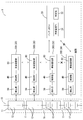
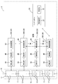
- FIG. 2 is a block diagram that embodies part of the battery monitoring system and the battery according to the first embodiment.
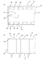
- FIG. 3A is a plan view partially and simply showing a configuration in which the battery monitoring device of the first embodiment is attached to the battery, and
- FIG. 3B is a front view thereof.
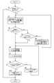
- FIG. 4 is a flowchart illustrating the flow of control executed by the battery ECU.
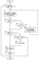
- FIG. 5 is a flowchart illustrating the flow of control executed by each battery monitoring device.
- FIG. 6 is an explanatory diagram conceptually illustrating a state of communication when all the battery monitoring devices are in a normal state in the battery monitoring system according to the first embodiment.
- FIG. 1 is a block diagram schematically illustrating an in-vehicle power supply system including the battery monitoring system according to the first embodiment.
- FIG. 2 is a block diagram that embodies part of the battery
- FIG. 7 is an explanatory diagram conceptually illustrating a state of communication when the lowest-level monitoring device is in an abnormal state in the battery monitoring system according to the first embodiment.
- FIG. 8 is an explanatory diagram conceptually illustrating a state of communication when the intermediate rank monitoring apparatus is in an abnormal state in the battery monitoring system according to the first embodiment.
- the battery monitoring device may have a substrate part that is assembled directly to the battery or indirectly through another member. At least the wireless communication unit may be mounted on the substrate unit.
- the substrate portion can be disposed near the battery, the size can be further reduced. Even if the board portion is arranged near the battery in this way, it is possible to transmit information to the outside wirelessly, so that it is difficult to complicate the routing design.
- the vehicle battery monitoring system may be configured to include a plurality of the battery monitoring devices and an external control device that receives information transmitted from any of the wireless communication units of the battery monitoring devices.
- the number of wires can be reliably reduced in a system that can transmit detection information (information indicating at least one of battery voltage and temperature) to the external control device by communication based on the detection result of the battery monitoring device. Can be realized.
- the battery monitoring system for vehicles may include three or more battery monitoring devices.
- any one device is determined as the highest-order monitoring device in the highest order, and any other device is determined as the lowest-order monitoring device in the lowest order.
- the intermediate-order monitoring device may be determined.
- the highest-level monitoring device wirelessly transmits wireless transmission data including detection information generated by the highest-level monitoring device with the next-order battery monitoring device lower than itself as the transmission destination May function as well.
- Each intermediate rank monitoring device adds detection information generated by itself to the given wireless transmission data when the wireless transmission data is given by wireless transmission from the battery monitoring device of the next higher rank than itself.
- the new wireless transmission data may be transmitted to a battery monitoring device of the next lower rank than itself.
- the wireless transmission data is given by wireless transmission from the battery monitoring device of the next higher rank than itself, the lowest-order monitoring device adds new detection information generated by itself to the given wireless transmission data. It is also possible to function to wirelessly transmit such wireless transmission data to the external control device.
- the information transmission order can be determined in a plurality of battery monitoring systems.
- the detection information generated by a plurality of battery monitoring devices is output to the outside, the detection information generated by each battery monitoring device can be collected in order starting from the highest-level monitoring device, and the collected data can be collected.
- Wireless transmission can be performed from the lowest-level monitoring device to the external control device.
- communication between the battery monitoring devices and communication from the lowest-order monitoring device to the external control device can be performed by wireless communication, so that the wiring reduction effect becomes extremely high.
- the detection information can be collected from the lowest level monitoring device and transmitted from the lowest level monitoring device to the external control device, it is compared with a configuration in which the external control device always communicates with all the battery monitoring devices. Thus, the burden on the external control device can be reduced.
- the external control device may function to wirelessly transmit command information for specifying a predetermined command to the lowest-level monitoring device.
- the lowest-level monitoring device displays the data including the command specified by the command information higher than itself.
- Each intermediate rank monitoring device receives a command specified by the command information when data including a command specified by the command information is given by wireless transmission from a battery monitoring device of the next lower rank than itself.
- the included data may function so as to be wirelessly transmitted with the battery monitoring device of the next higher rank than itself as the transmission destination.
- Each of the plurality of battery monitoring devices may function to perform control corresponding to the command specified by the command information when data including the command specified by the command information is received.
- the battery monitoring system capable of causing each of the plurality of battery monitoring devices to perform control according to the command from the external control device is reduced in the number of wires and the communication load of the external control device is reduced. realizable.
- the external control device may function to wirelessly transmit command information including a predetermined notification command to the lowest-level monitoring device.
- Each intermediate rank monitoring device transmits a battery monitoring device of the next higher rank than itself when data including a notification command is given by wireless transmission from the battery monitoring device of the next lower rank than itself. It may function to wirelessly transmit data including a notification command as a destination.
- the highest monitoring device uses the battery monitoring device of the next lower rank than itself as a transmission destination.
- the wireless transmission data including the detection information generated by the highest-level monitoring device may function to wirelessly transmit.
- Each of the intermediate rank monitoring devices is provided with the wireless transmission data when the data including the notification command is given and the wireless transmission data is given by the wireless transmission from the battery monitoring device of the next higher rank than itself. It is also possible to function to wirelessly transmit new wireless transmission data to which detection information generated by itself is added to a battery monitoring device of the next lower rank than itself.
- the lowest order monitoring device is provided with data including a notification command by wireless transmission from the external control device and wireless transmission data is provided by wireless transmission from the battery monitoring device of the next higher rank than itself, It may function to wirelessly transmit new wireless transmission data obtained by adding detection information generated by itself to given wireless transmission data to an external control device.
- a battery monitoring system capable of transmitting detection information (detection information indicating at least one of battery voltage and temperature) to each of the plurality of battery monitoring devices in response to a notification command from the external control device, This can be realized by reducing the number of wires and the communication load of the external control device.
- the detection unit of the battery monitoring device may be configured to detect voltage information that specifies a voltage between terminals of each battery cell in a battery formed by connecting a plurality of battery cells.
- the external control device may function to wirelessly transmit command information including a predetermined cell balance command to the lowest-level monitoring device.
- the lowest-order monitoring device transmits the data including the cell balance command to the next higher-order battery monitoring device. It may function to transmit wirelessly as a destination.
- Each of the intermediate rank monitoring devices when data including a cell balance command is given by wireless transmission from the next lower rank battery monitoring device, the next higher rank battery monitoring device. It may function to wirelessly transmit data including a cell balance command as a transmission destination.
- the plurality of battery cells are configured to equalize the voltage between the terminals of each of the battery cells based on the detection result by its own detection unit. It may function to control the charging or discharging.
- the battery monitoring system capable of causing each of the plurality of battery monitoring devices to perform cell balance control in response to a cell balance command from the external control device reduces the number of wires and reduces the communication burden of the external control device. It can be realized in a suppressed form.
- FIG. 1 schematically shows an in-vehicle power supply system 100.
- An in-vehicle power supply system 100 shown in FIG. 1 includes a battery 10, a battery monitoring system 1 that monitors the battery 10, and a power management ECU 120 (Electric Control Unit) that is provided so as to be communicable with the battery monitoring system 1.
- ECU 120 Electric Control Unit
- the battery 10 is, for example, a lithium ion battery including a plurality of battery cells 12, and uses, for example, electric power for driving an electric drive device (motor or the like) in a vehicle such as a hybrid vehicle or an electric vehicle (EV (Electric Vehicle)). Used as a power source for output.
- the battery 10 is charged by a power generator (not shown) mounted on the vehicle.
- the battery 10 includes one assembled battery 11 in which a plurality of battery cells 12 configured as lithium ion batteries are connected in series, and a predetermined number of assembled batteries 11 are arranged in series to form one stack 10A.
- the stack 10A is housed in a case.
- the battery 10 which can output a desired output voltage (for example, several hundred V) is comprised in the form where the stack 10A comprised in this way was connected in series.
- the battery monitoring system 1 includes a plurality of battery monitoring devices 30 and a battery ECU 20 as an external control device, and the plurality of battery monitoring devices 30 perform wireless communication with the battery ECU 20 (external control device). It has a configuration that can be performed. Further, each of the plurality of battery monitoring devices 30 is configured to be able to perform wireless communication with other battery monitoring devices 30.
- one battery monitoring device 30 is assigned to one assembled battery 11 constituting the battery 10.
- Each battery monitoring device 30 includes a detection unit 50 that detects the voltage and temperature of the assigned assembled battery 11, a control unit 40 that performs various controls such as control according to an external command, and other battery monitoring devices. 30 or a wireless communication unit 60 that performs wireless communication with the battery ECU 20.
- the control unit 40 shown in FIGS. 1 and 2 is configured by a microcomputer or other hardware circuit, and when at least the wireless communication unit 60 receives a command from the outside, it can perform control according to the command. If it is.
- the monitoring IC 32 is configured by integrating the control unit 40 and the detection / adjustment circuit unit 36. 2 conceptually shows the hardware configuration of the lowest-order monitoring device 30D among the plurality of battery monitoring devices 30, but the other battery monitoring devices 30 have the same hardware as the lowest-order monitoring device 30D.
- the hardware configuration is configured by a microcomputer or other hardware circuit, and when at least the wireless communication unit 60 receives a command from the outside, it can perform control according to the command. If it is.
- the monitoring IC 32 is configured by integrating the control unit 40 and the detection / adjustment circuit unit 36. 2 conceptually shows the hardware configuration of the lowest-order monitoring device 30D among the plurality of battery monitoring devices 30, but the other battery monitoring devices 30 have the same hardware as the lowest-order monitoring device 30D.
- the hardware configuration is configured
- the control unit 40 is configured as a microcomputer including a CPU, a ROM, a RAM, and the like.
- a predetermined notification command transmitted from the battery ECU 20 is directly or indirectly via another device.
- the wireless communication unit 60 receives the information, the temperature and voltage of the battery 10 are grasped based on a signal from the detection unit 50, and information on the temperature and voltage of the battery 10 is transmitted to the other battery monitoring device 30 or the battery ECU 20. Has a function of performing response processing.
- the control unit 40 is based on the detection result by the detection unit 50.
- the battery cell 12 has a function of performing a cell balance process for controlling charging or discharging of the plurality of battery cells 12 so as to make the voltage between the terminals of the battery cells 12 uniform.
- the detection unit 50 includes a detection / adjustment circuit unit 36 that functions as a voltage detection unit that detects a voltage at a predetermined position of the battery 10, and a temperature detection unit 38 that detects the temperature of the battery 10.
- the detection / adjustment circuit unit 36 detects voltage information specifying the voltage between the terminals of each battery cell 12 in the battery 10 to which the plurality of battery cells 12 are connected.
- the detection / adjustment circuit unit 36 includes a plurality of voltage signal lines 14 and a plurality of discharge units 16 respectively connected in parallel to the plurality of battery cells 12. In FIG. 2, some of the battery cells 12 (unit batteries) are omitted, and a circuit corresponding to the omitted battery cell 12 is also omitted.
- the plurality of voltage signal lines 14 are electrically connected to the inter-battery electrode portion 11C of the assembled battery 11 or the end electrode portions 11A and 11B of the assembled battery 11 in which the plurality of battery cells 12 are connected in series. It is connected to the.
- the electrode portion 11 ⁇ / b> A is an electrode portion at one end of the assembled battery 11, and is an electrode portion having the highest potential in the assembled battery 11.
- the electrode part 11 ⁇ / b> B is an electrode part at the other end of the assembled battery 11, and is an electrode part having the smallest potential in the assembled battery 11.
- the inter-battery electrode portion 11C is a portion in which the positive electrode on one side and the negative electrode on the other side are electrically connected between the batteries of the battery cells 12 (unit batteries) connected in series.
- the potential of the portion 11C increases as it approaches the electrode portion 11A.
- the plurality of voltage signal lines 14 are signal lines for inputting analog signals indicating the potentials of the electrode portions 11A, 11B, and 11C to the control unit 40.
- the control unit 40 can detect the terminal voltage of each battery cell 12 (unit battery) based on the analog voltage signal input via each voltage signal line 14.
- the control unit 40 includes an AD converter that converts each analog voltage signal input via each voltage signal line 14 into a digital signal. Since the control part 40 can grasp
- each voltage signal line 14 illustrates the current flowing from the battery cell 12 to the control unit 40 , but the current flowing from the battery cell 12 to the control unit 40 is limited by providing a current limiting resistor. Can do.
- a Zener diode (not shown) for clamping the voltage between the voltage signal lines at the time of overvoltage is connected in parallel with each battery cell 12 (specifically, the cathode is connected to the battery cell 12. It is desirable to connect the battery cell 12 in parallel with the positive electrode and the anode connected to the negative electrode.
- the temperature detection unit 38 is configured by, for example, a known temperature sensor, and is provided on the surface portion of the assembled battery 11 or the surface portion of the stack 10A shown in FIG. Arranged in contact or in close proximity without contact.
- the temperature detection unit 38 outputs a voltage value indicating the temperature at the arrangement position (that is, the surface temperature of the assembled battery 11 or the temperature near the surface) and inputs the voltage value to the control unit 40.
- the monitoring IC 32 including the control unit 40 and the detection / adjustment circuit unit 36 functions as a cell balance circuit that equalizes the respective voltages or capacities of the battery cells 12.
- the cell balance circuit is, for example, a circuit that eliminates the voltage variation of the plurality of battery cells 12 as much as possible and equalizes, for example, among the assembled batteries 11 assigned to the battery monitoring device 30.
- the battery cell 12 with the smallest potential difference (voltage between terminals) is detected, and the voltage of the other battery cell 12 is adjusted to the voltage of the detected battery cell 12 (that is, the battery cell 12 with the smallest voltage between terminals). It is conceivable to use a passive cell balance circuit that performs a discharge operation.
- the wireless communication unit 60 may be a circuit that performs wireless communication by a known wireless communication method, and the medium and frequency of the wireless signal are not limited. For example, radio waves can be suitably used for the mediation, but infrared rays or the like, or electromagnetic waves other than these may be used.
- the wireless communication unit 60 operates to receive a wireless signal when a wireless signal is transmitted from the wireless communication unit 60 of another battery monitoring device 30 or the wireless communication unit 24 of the battery ECU 20.
- the wireless communication unit 60 performs wireless transmission according to the control of the control unit 40 and transmits information related to the battery 10 to the wireless communication unit 60 of the other battery monitoring device 30 or the wireless communication unit 24 of the battery ECU 20. To work.
- the battery monitoring device 30 configured in this way is assembled to the battery 10 as shown in FIGS. 3A and 3B, for example.
- the battery monitoring device 30 has a substrate unit 70 configured as a known printed circuit board or the like, and the substrate unit 70 is directly fixed to the assembled battery 11 and integrated with the assembled battery 11. It is configured.
- the substrate unit 70 may be a rigid substrate or an FPC.
- a known bus bar substrate may be used.
- the substrate unit 70 may be a single layer substrate or a multilayer substrate.
- the monitoring IC 32 and the wireless communication unit 60 described above are mounted on the board unit 70 and integrated with the battery 10 via the board unit 70. In FIG. 3, wiring patterns and other electronic components formed on the substrate unit 70 are omitted.
- the substrate portion 70 is fixed to the terminal portions 12 ⁇ / b> A and 12 ⁇ / b> B (protrusions constituting the positive electrode or the negative electrode) of the battery cell 12 constituting the assembled battery 11, and the terminal portions 12 ⁇ / b> A and 12 ⁇ / b> B are electrically connected.
- the above-described voltage signal line 14 connected to is formed as a wiring pattern in the substrate portion 70.
- the terminal portion 12A is a protrusion that constitutes the positive electrode of the battery cell 12
- the terminal portion 12B is a protrusion that constitutes the negative electrode of the battery cell.
- the structure shown in FIG. 3 is an example of an attachment structure to the last, and is not limited to this example.
- substrate part 70 does not need to be directly fixed to the battery 10, and may be indirectly assembled
- the temperature sensor that constitutes the temperature detection unit 38 shown in FIGS. 1 and 2 may be mounted on the board unit 70 at a position in contact with the battery 10 or a position close to the battery 10, but not on the board unit 70.
- the battery 10 may be fixed directly or indirectly via another member.
- the temperature detection unit 38 and the substrate unit 70 may be electrically connected via a wiring unit or the like.
- the battery ECU 20 illustrated in FIG. 1 corresponds to an example of an external control device, and is configured as an electronic control device that can receive information transmitted from the wireless communication unit 60 of the battery monitoring device 30 and can perform various controls. It is configured. Battery ECU 20 can communicate with an external ECU (power management ECU 120 in FIG. 1) shown in FIG.
- the battery ECU 20 includes a wireless communication unit 24 that performs wireless communication and a determination unit 22 that performs various determinations such as a voltage abnormality determination.
- the battery ECU 20 includes a wireless communication unit 60 and a known microcomputer 21 (also referred to as a microcomputer 21), and the microcomputer 21 functions as the determination unit 22.
- the microcomputer 21 includes, for example, a CPU, a storage unit (ROM, RAM, etc.), an AD converter, and the like, and can perform various controls.
- the battery ECU 20 configured in this way is configured to be able to wirelessly communicate with each battery monitoring device 30.
- one of the battery monitoring devices 30 is set as a communication target, and at the time of reception, information wirelessly transmitted from the wireless communication unit 60 of the battery monitoring device 30 as a communication target is received. . In transmission, information is wirelessly transmitted to the wireless communication unit 60 of the battery monitoring device 30 to be communicated.
- the battery monitoring system 1 configured as described above can be arranged at a predetermined position in the vehicle in a form housed in a metal case together with the battery 10, for example.
- the case in which the battery 10 and the battery monitoring system 1 are housed in this way is preferably disposed in the vehicle away from noise generation sources such as a motor and an alternator that serve as a driving power source. It can arrange suitably in the lower position etc. of the seat provided in.
- the battery monitoring system 1 may be provided near the rear end of the vehicle.
- the battery monitoring system 1 may be provided near the front end of the vehicle.
- these examples are only preferable examples and can be arranged at various positions in the vehicle.
- the battery ECU 20 can perform wireless communication or wired communication with a power management ECU 120 provided outside, but the power management ECU 120 may be disposed outside the metal case described above. It may be arranged inside.
- the battery ECU 20 accommodated in the case and the power management ECU 120 disposed outside the case are connected to be communicable via a communication line such as a CAN communication line so that information can be transmitted and received between them. May be.
- the battery monitoring system 1 includes three or more battery monitoring devices 30 and a battery ECU 20 (external control) that receives information transmitted from any one of the plurality of battery monitoring devices 30. Device).
- a battery ECU 20 external control
- the battery ECU 20 and the lowest-order monitoring device 30D can directly perform wireless communication with each other without using other devices as in the example of FIG. 6 will be described as a representative example.
- the lowest-order monitoring device 30D may be configured to perform wireless communication with each other via the relay device.
- a plurality of battery monitoring devices 30 transmit information in series, and a basic order for transmitting information is determined in advance. Specifically, of the four battery monitoring devices 30, any one device is determined as the highest-order monitoring device 30A in the highest order (rank 1), and any other device is ranked in the lowest order (rank). 4) is defined as the lowest-order monitoring device 30D.
- the devices other than the highest-level monitoring device 30A and the lowest-level monitoring device 30D are defined as intermediate rank monitoring devices 30B and 30C.
- the intermediate rank monitoring device 30B is a battery monitoring device 30 of rank 2
- the intermediate ranking monitoring device 30C is a battery monitoring device of rank 3.
- Each battery monitoring device 30 is assigned a unique ID, and the assigned unique ID is stored in a storage unit (not shown). For example, a unique ID 1 is assigned to the highest order monitoring apparatus 30A, a unique ID 2 is assigned to the intermediate order monitoring apparatus 30B, a unique ID 3 is assigned to the intermediate order monitoring apparatus 30C, and the lowest order monitoring apparatus 30D is assigned. Is assigned a unique ID 4.
- the battery with the highest (smallest) rank Transmission is performed so that information is passed in order from the device with the highest priority, starting from the highest-order monitoring device 30A, which is the monitoring device 30.
- the highest-ranking monitoring device 30A of rank 1 receives the battery monitoring device 30 of the next rank lower than itself (that is, rank) in response to establishment of a predetermined transmission condition (for example, reception of command information including a notification command).
- Wireless transmission data including detection information generated by the highest-order monitoring device 30A is transmitted wirelessly with the second intermediate-order monitoring device 30B) as a transmission destination.
- Each of the intermediate rank monitoring devices 30B and 30C is generated by itself in the given wireless transmission data when the wireless transmission data is given by wireless transmission from the battery monitoring device 30 of the next higher rank than itself.
- the new wireless transmission data to which the detection information is added is transmitted to the battery monitoring device 30 of the next lower rank than itself.
- the intermediate rank monitoring device 30B includes wireless detection transmission information including the detection information of the highest-order monitoring device 30A by wireless transmission from the next higher-order battery monitoring device 30 (that is, the highest-order monitoring device 30A of rank 1).
- the new wireless transmission data obtained by adding the detection information generated by itself to the given wireless transmission data is used as the next lower battery monitoring device 30 (that is, the middle of the ranking 3). To the rank monitoring device 30C).
- the intermediate rank monitoring apparatus 30C performs the wireless transmission from the next higher rank battery monitoring apparatus 30 (that is, the intermediate rank monitoring apparatus 30B of rank 2) of the highest rank monitoring apparatus 30A and the intermediate rank monitoring apparatus 30B.
- wireless transmission data including detection information new wireless transmission data obtained by adding the detection information generated by itself to the given wireless transmission data is assigned to the battery monitoring device 30 of the next lower rank than itself ( In other words, the data is transmitted to the lowest-order monitoring device 30D) of rank 4.
- the lowest-order monitoring device 30D transmits the highest-order monitoring device 30A and the intermediate-order monitoring devices 30B and 30C by wireless transmission from the battery monitoring device 30 of the next higher rank than itself (that is, the intermediate-order monitoring device 30C of rank 3).
- new wireless transmission data obtained by adding the detection information generated by itself to the given wireless transmission data is wirelessly transmitted to the battery ECU 20 (external control device).
- data including detection information obtained by each of the plurality of battery monitoring devices 30 is transmitted from the lowest-order monitoring device 30D to the battery ECU 20 by wireless communication.
- the above operation is a basic operation when information from the plurality of battery monitoring devices 30 is transmitted to the battery ECU 20.
- the command information (command information for specifying a predetermined command) from the battery ECU 20 (external control device) when the battery monitoring system 30 is in a normal state in which no failure has occurred in these battery monitoring devices 30.
- information is transmitted as follows. First, the battery ECU 20 wirelessly transmits command information to the lowest order monitoring device 30D.
- the lowest-order monitoring device 30D is specified by the command information when data corresponding to the command information (data including the command specified by the command information) is given by wireless transmission from the battery ECU 20 (external control device). Is transmitted wirelessly with the next higher rank battery monitoring device 30 (that is, the intermediate ranking monitoring device 30C of ranking 3) as the transmission destination.
- the data including the command specified by the command information may be the command information itself or data obtained by processing the command information.
- the intermediate rank monitoring device 30C is given data including a command specified by the command information by wireless transmission from the battery monitoring device 30 of the next lower rank than itself (that is, the lowest-order monitoring device 30D of the rank 4).
- the data including the command specified by the command information is wirelessly transmitted to the battery monitoring device 30 of the next higher rank than itself (that is, the intermediate ranking monitoring device 30B of the ranking 2) as the transmission destination.
- the intermediate rank monitoring device 30B is given data including a command specified by the command information by wireless transmission from the battery monitoring device 30 of the next lower rank than itself (that is, the intermediate rank monitoring device 30C of the rank 3).
- the data including the command specified by the command information is wirelessly transmitted with the next higher-order battery monitoring device 30 (that is, the highest-level monitoring device 30A of the first rank) as the transmission destination.
- the battery monitoring device 30 corresponds to the command specified by the command information. Control.
- the battery ECU 20 performs control according to the flow shown in FIG. Specifically, the control of FIG. 4 is executed by the microcomputer 21 of the battery ECU 20, and the microcomputer 21 continuously repeats the control of FIG. 4 at short time intervals while the ignition switch is on.
- the battery ECU 20 determines whether or not there is a notification request from the power management ECU 120 after starting the control of FIG.
- the power management ECU 120 is configured to transmit information indicating a predetermined notification request (request to notify the state of the battery 10) to the battery ECU 20 at a predetermined timing. It is determined whether or not there is a notification request.
- the timing at which the notification request is transmitted from the power management ECU 120 to the battery ECU 20 may be, for example, immediately after the ignition switch is switched from the OFF state to the ON state, or any other predetermined diagnostic timing. It may be.
- step S2 the battery ECU 20 selects the lowest-ranked (highest-ranked) device among the plurality of battery monitoring devices 30 that are communication candidates.
- the command information including the unique ID of the target device and a predetermined notification command is transmitted to the target device.
- the notification command is a command for instructing the battery monitoring device 30 to transmit information on predetermined items.
- the communication candidates in step S2 are obtained by excluding the battery monitoring devices 30 (battery monitoring devices 30 determined to be faulty) excluded in step S5 from all the battery monitoring devices 30. For example, when the process of step S5 is not yet executed and all the battery monitoring devices 30 are in the normal state as shown in FIG.
- the battery ECU 20 In step S2, the lowest-order monitoring device 30D that is the lowest-ranked (highest-ranked) device among all the battery monitoring devices 30 is the target device, and the unique ID of the lowest-order monitoring device 30D is assigned to this target device.
- Command information including (unique ID 4) and a predetermined notification command is transmitted. For example, when each battery monitoring device 30 acquires information including its own unique ID, the battery monitoring device 30 performs processing according to the information, and when receiving information that does not include its own unique ID, Discard or ignore.
- the battery ECU 20 transmits the command information for any one of the battery monitoring devices 30 in step S2
- the battery ECU 20 determines whether communication is established with the battery monitoring device 30 that is the target. For example, when each battery monitoring device 30 receives command information including its own unique ID, the battery ECU 20 returns predetermined response information, and the battery ECU 20 monitors one of the battery monitoring devices in step S2.
- the command information including the unique ID of the battery monitoring device 30 is transmitted for the device 30 and it is determined that the response information corresponding to the transmission is received for a certain time after the transmission (step S3 If YES in step S6, the process of step S6 is performed. If it is determined that the message has not been received (NO in step S3), the process of step S4 is performed.
- step S2 when the battery ECU 20 transmits the command information including the unique ID (ID4) of the lowest-order monitoring device 30D with the lowest-order monitoring device 30D as a communication target in step S2, the battery ECU 20 receives the command information for a certain time after the transmission. If it is determined that the response information corresponding to the transmission has not been received, the process proceeds to step S4.
- ID4 the unique ID
- step S4 the battery ECU 20 communicates again with the battery monitoring device 30 that is the communication target at step S2 for a certain time or a certain number of times, and is communication established with the battery monitoring device 30? It is determined again whether or not. If the battery ECU 20 determines that the communication is established when the communication is performed again in step S4 (Yes in step S4), the process is performed in step S6, and the communication is established even if the communication is performed again in step S4. If it is determined that it has not been performed (No in step S4), the process of step S5 is performed.
- step S5 When performing the process of step S5, the battery ECU 20 determines that the battery monitoring device 30 communicated in the latest steps S2 and S4 is a failure and excludes it from the transmission candidates, and then performs the process of step S2 again.
- step S2 When the process of step S2 is performed after step S5, the command information is transmitted to the battery monitoring apparatus with the lowest rank among the new transmission candidates excluding the battery monitoring apparatus 30 excluded from the transmission candidates in step S5. For example, as shown in FIG. 7, when the lowest-order monitoring device 30D is out of order, communication is not established even if communication is performed with the lowest-order monitoring device 30D in the first step S2, and thus the process proceeds to step S4. Since communication is not established even in S4, the process proceeds to step S5.
- step S5 the plurality of battery monitoring devices 30 (the highest-level monitoring device 30A and the intermediate-level monitoring devices 30B and 30C) excluding the lowest-level monitoring device 30D become new transmission candidates.
- the command information including the unique ID of the intermediate rank monitoring apparatus 30C is transmitted to the intermediate rank monitoring apparatus 30C having the lowest (larger) rank among the transmission candidates.
- step S6 the process proceeds to step S6. In this case, it waits for information to be transmitted from the battery monitoring device 30 according to the command information. The processing after step S6 will be described later.
- Each battery monitoring device 30 performs control according to the flow shown in FIG.
- the control in FIG. 5 is executed by, for example, the control unit 40 of each battery monitoring device 30, and each control unit 40 continuously repeats the control in FIG. 4 at short time intervals while the ignition switch is on. .
- each battery monitoring device 30 After starting the control of FIG. 5, the control unit 40 determines whether or not the command information is received in step S21.
- the control unit 40 of each battery monitoring device 30 receives command information wirelessly transmitted from the battery ECU 20 or the battery monitoring device 30 with a lower rank, the process proceeds to Yes in step S21, and the command information is set as a transmission candidate. It transmits to the battery monitoring device 30 with the lowest rank among the battery monitoring devices 30 (higher transmission candidates) with higher rank than itself.
- the unique ID of the destination battery monitoring device 30 is included in the command information. For example, as shown in FIG.
- step S21 when all the battery monitoring devices 30 are in a normal state, when command information is transmitted from the battery ECU 20 to the lowest-order monitoring device 30D, the lowest-order monitoring device 30D that has received this command information. Becomes Yes in step S21, and the intermediate rank monitoring apparatus 30C having the lowest rank among the highest rank monitoring apparatus 30A and the intermediate rank monitoring apparatuses 30B and 30C, which are upper transmission candidates, is set as the transmission destination. Command information including the unique ID is transmitted. Alternatively, when the command information is transmitted from the lowest order monitoring device 30D to the intermediate rank monitoring device 30C, the intermediate rank monitoring device 30C that has received this command information becomes Yes in step S21 of the control in FIG.
- the command information including the unique ID of the intermediate rank monitoring apparatus 30B is transmitted to the intermediate rank monitoring apparatus 30B having the lowest rank among the highest rank monitoring apparatus 30A and the intermediate rank monitoring apparatus 30B.
- the intermediate rank monitoring device 30B that has received this command information becomes Yes in step S21 of the control in FIG.
- Command information including the unique ID of the highest-level monitoring device 30A is transmitted to the candidate, the highest-level monitoring device 30A.
- the command information wirelessly transmitted from the battery ECU 20 to any one of the battery monitoring devices 30 is thus transmitted to the upper side.
- the battery monitoring device 30 performs the process of step S22 and returns response information to the transmission source.
- step S22 When each battery monitoring device 30 transmits command information for any one of the higher-level battery monitoring devices 30 in step S22, communication is performed with the target battery monitoring device 30 in step S23. It is determined whether or not it is established.
- step S22 when the battery monitoring device 30 targets any one of the battery monitoring devices 30 and transmits the command information including the unique ID of the battery monitoring device 30, the battery monitoring device 30 transmits the command information for a certain time after the transmission. If it is determined that the response information corresponding to is not received (No in Step S23), the process of Step S24 is performed. If it is determined that the response information is received (Yes in Step S23), the process of Step S26 is performed. I do.
- step S22 If it is determined that the response information corresponding to the transmission has not been received, the process proceeds to step S24.
- step S24 the battery monitoring device 30 communicates again with the battery monitoring device 30 that is the communication target in step S22 for a certain time or a certain number of times, and the communication with the battery monitoring device 30 is established. It is determined again whether or not. If the battery monitoring device 30 determines that the communication is established when the communication is performed again in step S24 (Yes in step S24), the battery monitoring device 30 performs the process of step S26, and performs the communication again in step S24. If it is determined that communication has not been established (No in step S24), the process of step S25 is performed.
- the battery monitoring apparatus 30 determines that the battery monitoring apparatus 30 communicated in the most recent steps S22 and S24 is a failure and excludes it from the upper transmission candidates, and then performs the process of step S22 again. Do.
- the battery monitoring apparatus 30 with the lowest rank among the new upper transmission candidates excluding the battery monitoring apparatus 30 excluded from the upper transmission candidates in step S25 is set as the transmission destination.
- Command information including the unique ID of the battery monitoring device 30 is transmitted. For example, if the lowest order monitoring device 30D performs the control shown in FIG. 5 when the intermediate rank monitoring device 30C is out of order as shown in FIG.
- step S24 the process proceeds to step S24. Since communication is not established even in step S24, the process proceeds to step S25.
- step S25 among the battery monitoring devices 30 with higher (smaller) rank than the lowest-order monitoring device 30D, a plurality of battery monitoring devices 30 (the highest-level monitoring device 30A, the intermediate ranking) excluding the intermediate ranking monitoring device 30C.
- the monitoring device 30B becomes a new higher-order transmission candidate, and in the subsequent step S22, the unique ID of the intermediate-order monitoring device 30B with the lowest-order (larger) intermediate-order monitoring device 30B among the new higher-order transmission candidates as a transmission target.
- the command information including is transmitted.
- the intermediate rank monitoring apparatus 30C is skipped from the lowest rank monitoring apparatus 30D, and the command information is wirelessly transmitted to the intermediate rank monitoring apparatus 30B.
- the top-level monitoring device 30A omits steps S22 to S25 when performing the control of FIG. Further, as a result of the exclusion process performed by the battery monitoring device 30 in step S25, if there is no higher transmission candidate, the process may proceed to step S26.
- Each battery monitoring device 30 determines whether or not a predetermined notification command is included in the received command information (command information including its own unique ID) when performing the process of step S26.
- the voltage and temperature are detected in step S29.
- the control unit 40 of the battery monitoring device 30 that performs the process of step S26 assigns the battery monitoring device 30 based on the analog voltage value input via each voltage signal line 14 illustrated in FIG.
- the voltage between the terminals of each battery cell 12 of the assembled battery 11 is calculated.
- the temperature of the battery 10 (specifically, the temperature of the assigned assembled battery 11) is grasped based on the detection value input from the temperature detection unit 38.
- the control unit 40 detects the voltage between the terminals of each battery cell 12 and the temperature of the assembled battery 11 in step S29, and then wirelessly transmits the information in step S30. For example, when the highest-level monitoring device 30A executes the process of step S30 in the control of FIG. 5, the highest-level monitoring device 30A becomes a transmission starting point, and the lower-level battery monitoring device 30 that gives command information to the highest-level monitoring device 30A.
- the wireless transmission data including the information (detection information) detected in step S29 is transmitted. If any of the battery monitoring devices 30 performs the process of step S25 and there is no higher transmission candidate and the process proceeds to step S26, the battery monitoring device 30 becomes a transmission start point, and a command is sent to the battery monitoring device 30.
- the wireless transmission data including the information (detection information) detected in step S29 is transmitted to the lower battery monitoring device 30 that has given the information.
- the device that has received the command information from another battery monitoring device 30 executes the process of step S30 in the control of FIG.
- the wireless monitoring data is received from the host battery monitoring device 30 (the device determined to have established communication in step S23 or step S24) to which the battery monitoring device 30 has given the command information in the control of FIG.
- the wireless transmission data is added with the information (detection information) detected by itself in step S29 to generate new wireless transmission data, and the new wireless transmission data is subordinate to the command information given to the battery monitoring device 30.
- Wireless transmission to the battery monitoring device 30 is performed.
- the device that has received the command information from the battery ECU 20 executes the process of step S30 in the control of FIG. 5, and the battery monitoring device 30 receives the command information in the control of FIG.
- the wireless transmission data from the battery monitoring device 30 (the device determined to have established communication in step S23 or step S24)
- the information (detection information) detected by itself in step S29 is received for this wireless transmission data.
- new wireless transmission data is generated, and the new wireless transmission data is wirelessly transmitted to the battery ECU 20.
- step S3 or step S4 the battery ECU 20 waits for a certain period of time and then responds to the transmitted command information (each battery monitoring device 30 performs the process of step S29. Receive voltage and temperature information). Specifically, wireless transmission data (data transmitted by the battery monitoring device 30 in step S30) wirelessly transmitted from the battery monitoring device 30 determined to have established communication in step S3 or step S4 is received.
- Battery ECU20 performs the process of step S7 after receiving wireless transmission data from the battery monitoring apparatus 30 by the process of step S6, and determines the state of the battery 10 based on the received wireless transmission data.
- the determination unit 22 that is, the microcomputer 21 calculates the voltage (battery voltage) of the entire battery 10 based on the wireless transmission data (data including detection information of the plurality of battery monitoring devices 30).
- the voltage of the whole battery 10 can be calculated by integrating the whole voltage of each assembled battery 11 to which each battery monitoring device 30 is assigned.
- the voltage across the battery 10 can be calculated by integrating the inter-terminal voltages of all the battery cells 12.
- the determination unit 22 determines whether or not the battery 10 overall voltage (battery voltage) calculated in this way is an overcharged state exceeding a predetermined first threshold value, and the battery voltage is lower than the first threshold value. It is determined whether or not the overdischarge state is less than the second threshold value. Furthermore, based on the temperature information obtained from each battery monitoring device 30, it is determined whether or not the temperature of any assembled battery 11 is in an overheated state exceeding a predetermined temperature threshold. As described above, the determination unit 22 determines whether or not the voltage and temperature of the battery 10 are abnormal based on the detection information received by the wireless communication unit 24.
- the battery ECU 20 determines whether or not the variation in the voltage between the terminals of the plurality of battery cells 12 is within a certain value in each assembled battery 11 (step S8). For example, the inter-terminal voltage of the battery cell 12 having the highest inter-terminal voltage in any of the assembled batteries 11 based on the wireless transmission data (data including detection information of the plurality of battery monitoring apparatuses 30) received from the battery monitoring apparatus 30 And the difference between the terminal voltage of the battery cell 12 having the smallest terminal voltage exceeds a predetermined value, and if the difference exceeds a predetermined value in any of the assembled batteries 11 (Yes in step S8) In step S9, command information including a cell balance command for commanding the battery monitoring device 30 or all the battery monitoring devices 30 to which the assembled battery 11 is assigned is transmitted.
- command information including the cell balance command is given to the battery monitoring device 30 determined to have established communication in step S3 or step S4.
- Wireless transmission Since each battery monitoring device 30 repeatedly performs the control of FIG. 5, the command information wirelessly transmitted in this way follows the same flow as the above-described command information (command information including a notification command). Is transmitted to the device 30.
- each battery monitoring device 30 receives the command information including the notification command, it transmits the command information to the upper side in step S22, and then executes the processes of steps S29 and S30.
- the command information including the command is received, the command information is transmitted to the upper side in step S22, and then the processes of steps S27 and S28 are executed.
- the cell balance command is a command for causing the battery monitoring device 30 to execute cell balance processing, and is, for example, a command specified by predetermined information.
- each battery monitoring device 30 determines whether or not a cell balance command has been issued in step S ⁇ b> 27 in the process of FIG. 5 that is repeated at short time intervals, and the cell balance command is included in the received command information. If it is included (No in step S26, Yes in step S27), cell balance processing is performed in step S28. Specifically, the battery monitoring device 30 to which the cell balance command is given matches the output voltage of the battery cell 12 having the lowest output voltage among the plurality of battery cells 12 constituting the assembled battery 11 assigned to itself. In addition, the detection / adjustment circuit unit 36 is caused to perform the operation of discharging the remaining battery cells 12.
- a discharge unit 16 for discharging each battery cell 12 is connected to the detection / adjustment circuit unit 36, and the control unit 40 controls the operation of the discharge unit 16 to control the assigned assembled battery 11.
- the voltage between terminals of all the battery cells 12 is equalized so as to be approximately the same.
- step S28 of FIG. 5 the battery monitoring device 30 performs the process of step S29 described above again, and the terminals of the battery cells 12 after the cell balancing process in the assigned assembled battery 11 are performed. The inter-voltage and the temperature of the assembled battery 11 are detected. Then, the process of step S30 is performed, and the information detected in step S29 is transmitted as wireless transmission data. After the cell balance processing is performed in each battery monitoring device 30 in this way, the detection information generated by each battery monitoring device 30 in step S29 is collected into wireless transmission data and wirelessly transmitted to the battery ECU 20. Become.
- the battery ECU 20 waits for a certain period of time in step S6 when the cell balance command is transmitted in step S9 of FIG. 4, and when the wireless transmission data is received again from the battery monitoring device 30, the process after step S7 is performed. Do it again.
- step S10 The battery state is transmitted to the external ECU (power management ECU 120). Specifically, based on the determination result in the most recent step S7, information indicating whether or not the battery voltage is in an overcharged state exceeding a predetermined first threshold, and an overdischarge state in which the battery voltage is less than the second threshold Information indicating whether or not the battery pack 11 is in an overheated state in which the temperature of any one of the assembled batteries 11 exceeds a predetermined temperature threshold is transmitted to the power management ECU 120. In addition to this, various information such as the SOC, SOH, and internal resistance of the battery 10 may be transmitted.
- the battery monitoring device 30 can transmit the detection information (information indicating at least one of the voltage and the temperature of the battery 10) based on the detection result of the detection unit 50 to the other battery monitoring device 30, the other battery monitoring is performed. Detection information can be transmitted using the device 30. In addition, the characteristic information transmission using the other battery monitoring device 30 can be realized by wireless communication in this way, so that the number of wirings can be effectively reduced.
- the battery monitoring device 30 has a substrate unit 70 that is directly or indirectly assembled to the battery 10 via another member. At least the wireless communication unit 60 is mounted on the substrate unit 70.
- the substrate portion 70 can be disposed near the battery 10, further downsizing can be achieved.
- substrate part 70 is arrange
- transmission of the information to the exterior can be performed by radio
- the battery monitoring system 1 includes a plurality of battery monitoring devices 30 and a battery ECU 20 (external control device) that receives information transmitted from any of the wireless communication units 60 of the battery monitoring devices 30. ing.
- a system that can transmit detection information (information indicating at least one of the voltage and temperature of the battery 10) based on the detection result in the battery monitoring device 30 to the battery ECU 20 (external control device) by communication. This can be realized with a reduced number of wires.
- the battery monitoring system 1 is configured to include three or more battery monitoring devices 30.
- any one device is defined as the highest-order monitoring device 30A, and any other device is defined as the lowest-order monitoring device 30D.
- the devices other than the upper monitoring device 30A and the lowest monitoring device 30D are defined as intermediate rank monitoring devices 30B and 30C.
- the highest-level monitoring device 30A includes wireless transmission data including detection information generated by the highest-level monitoring device 30A with the next-order battery monitoring device 30 lower than itself as a transmission destination in response to establishment of a predetermined transmission condition. Function to wirelessly transmit.
- Each of the intermediate rank monitoring devices 30B and 30C is generated by itself in the given wireless transmission data when the wireless transmission data is given by wireless transmission from the battery monitoring device 30 of the next higher rank than itself. It functions to transmit new wireless transmission data to which the detection information is added to the battery monitoring device 30 of the next lower rank than itself.
- the lowest-order monitoring device 30D adds detection information generated by itself to the given wireless transmission data. It functions to wirelessly transmit the new wireless transmission data to the battery ECU 20 (external control device).
- the information transmission order can be determined in the plurality of battery monitoring systems 1.
- the detection information generated by the plurality of battery monitoring devices 30 is output to the outside, the detection information generated by each battery monitoring device 30 can be collected in order starting from the highest-level monitoring device 30A.
- the data can be wirelessly transmitted from the lowest-order monitoring device 30D to the battery ECU 20 (external control device).
- the communication between the battery monitoring devices 30 and the communication from the lowest-order monitoring device 30D to the battery ECU 20 (external control device) can be performed by wireless communication, so the wiring reduction effect is extremely high. .
- the battery ECU 20 (external control device) always has all the battery monitoring devices. Compared with a configuration in which communication is performed with 30, it is possible to reduce the burden on the battery ECU 20 (external control device).
- the battery ECU 20 wirelessly transmits command information for specifying a predetermined command to the lowest-order monitoring device 30D. Function.
- the lowest order monitoring device 30D receives data (command information itself or data obtained by processing the command information) including the command specified by the command information by wireless transmission from the battery ECU 20 (external control device), It functions to wirelessly transmit data including the command specified by the information, with the next higher battery monitoring device 30 (intermediate ranking monitoring device 30C) as the transmission destination.
- Each of the intermediate rank monitoring devices 30B and 30C is specified by the command information when data including a command specified by the command information is given by wireless transmission from the battery monitoring device 30 of the next lower rank than itself. It functions to wirelessly transmit the data including the command to be transmitted to the battery monitoring device 30 of the next higher rank than itself as the transmission destination.
- Each of the plurality of battery monitoring devices 30 functions to perform control corresponding to the command specified by the command information when data including the command specified by the command information is received.
- the battery monitoring system 1 capable of causing each of the plurality of battery monitoring devices 30 to perform control in accordance with a command from the battery ECU 20 (external control device) has a reduced number of wires and the battery ECU 20 (external control). This can be realized with a reduced communication burden on the device.
- the battery ECU 20 (external control device) functions to wirelessly transmit command information including a predetermined notification command to the lowest-order monitoring device 30D.
- the battery ECU 20 external control device
- Each of the intermediate rank monitoring devices 30B and 30C receives the battery including the notification command by wireless transmission from the battery monitoring device 30 of the next lower rank than itself. It functions to wirelessly transmit data including a notification command with the monitoring device 30 as a transmission destination.
- the highest-level monitoring device 30A It functions to wirelessly transmit wireless transmission data including detection information generated by the highest-order monitoring device 30A with the battery monitoring device 30 (intermediate ranking monitoring device 30B) as the transmission destination.
- Each of the intermediate rank monitoring devices 30B and 30C is given when data including a notification command is given and wireless transmission data is given by wireless transmission from the battery monitoring device 30 of the next higher rank than itself. It functions to wirelessly transmit new wireless transmission data obtained by adding detection information generated by itself to the wireless transmission data to the battery monitoring device 30 of the next lower rank than itself.
- the lowest-order monitoring device 30D is given data including a notification command by wireless transmission from the battery ECU 20 (external control device), and from the next higher-order battery monitoring device 30 (intermediate ranking monitoring device 30C).
- wireless transmission data is given by wireless transmission
- new wireless transmission data obtained by adding detection information generated by itself to the given wireless transmission data is wirelessly transmitted to the battery ECU 20 (external control device).
- detection information (detection information indicating at least one of the voltage and the temperature of the battery 10) is transmitted to each of the plurality of battery monitoring devices 30 in response to a notification command from the battery ECU 20 (external control device).
- the obtained battery monitoring system 1 can be realized with a reduced number of wires and a reduced communication burden on the battery ECU 20 (external control device).
- the detection unit 50 of the battery monitoring device 30 is configured to detect voltage information that specifies the voltage between terminals of each battery cell 12 in the battery 10 to which a plurality of battery cells 12 are connected.
- the battery ECU 20 (external control device) functions to wirelessly transmit command information including a predetermined cell balance command to the lowest level monitoring device 30D when the lowest level monitoring device 30D is in a communicable state.
- the lowest-order monitoring device 30D converts the data including the cell balance command to the next higher rank than itself. It functions to wirelessly transmit the battery monitoring device 30 (intermediate rank monitoring device 30C) as a transmission destination.
- Each of the intermediate rank monitoring devices 30B and 30C has the next higher rank than itself when the data including the cell balance command is given by wireless transmission from the battery monitoring device 30 of the next lower rank than itself. It functions to wirelessly transmit data including a cell balance command with the battery monitoring device 30 as a transmission destination.
- the plurality of battery monitoring devices 30 receives data including a cell balance command, the plurality of battery monitoring devices 30 are configured to equalize the inter-terminal voltage of each battery cell 12 based on the detection result by its own detection unit 50. It functions to control charging or discharging of the battery cell 12.
- the battery monitoring system 1 that can cause each of the plurality of battery monitoring devices 30 to perform cell balance control in response to a cell balance command from the battery ECU 20 (external control device) reduces the number of wires and This can be realized with a reduced communication burden on the ECU 20 (external control device).
- each battery cell 12 is configured to be capable of being discharged individually, and the example in which the voltage between terminals is uniformed by the discharge control of each battery cell 12 is shown. The voltage between the terminals may be made uniform by charge control or discharge control of the battery cell 12.
- one battery monitoring device 30 is assigned to one assembled battery 11, but one battery monitoring device 30 may be assigned to a plurality of assembled batteries 11. Alternatively, one assembled battery 11 may be divided into a plurality of areas, and the battery monitoring device 30 may be assigned to each area.
- Example 1 although the board
- the battery ECU 20 is illustrated as an example of the external control device.
- the battery ECU 20 is not limited to the battery ECU 20 as long as it is an in-vehicle electronic control device provided outside the battery monitoring device 30.
- the example in which the battery monitoring device 30 is assigned to the assembled battery 11 in which a plurality of battery cells 12 are aggregated is shown. May be assembled.
- Example 1 although each battery monitoring apparatus 30 demonstrated control of FIG. 5, the example which detects the voltage between the terminals of each battery cell 12 which comprises the assembled battery 11, and the temperature of the assembled battery 11 in step S29 was demonstrated. Alternatively, the overall voltage, internal resistance, capacity, and deterioration degree of the assembled battery 11 or the internal resistance, capacity, and deterioration degree of each battery cell 12 may be calculated, and these pieces of information may be wirelessly transmitted in step S30.
- the command information including the cell balance command is transmitted in step S9 and the cell ballast processing is performed in all the battery monitoring devices 30.
- the cell balance command may be given only to the battery monitoring device 30 assigned to the assembled battery 11 in which the variation in the inter-terminal voltage of the battery cell 12 is not within a certain value.
- the battery ECU 20 transmits command information that associates a unique ID that designates the battery monitoring device 30 with a cell balance command, and the battery monitoring device 30 side associates a cell balance command that is associated with its own unique ID. Cell balance processing may be performed.
- wireless communication may be performed indirectly via a relay device.
- the command information wirelessly transmitted from the battery ECU 20 may be temporarily received by the relay device, and the command information transmitted from the relay device may be received by any of the battery monitoring devices 30.
- the wireless transmission data wirelessly transmitted from any one of the battery monitoring devices 30 may be temporarily received by the relay device, and the wireless transmission data transmitted from the relay device may be received by the battery ECU 20.
- both direct wireless communication and indirect wireless communication via a relay device may be performed as wireless communication between the battery ECU 20 and the battery monitoring device 30.
Abstract
La présente invention met en œuvre un dispositif de surveillance de batterie de véhicule et un système de surveillance de batterie de véhicule qui sont aptes à aider à réduire le nombre de câblages et à transmettre des informations en utilisant un trajet de transmission caractéristique. Le dispositif de surveillance de batterie (30) comprend : une unité de détection (50) qui détecte une tension à un point prescrit de la batterie (10) et/ou une température de la batterie (10) ; et une unité de communication sans fil (60) qui, par l'intermédiaire d'un schéma de communication sans fil, transmet les informations de détection, représentant la tension et/ou la température de la batterie (10), à un autre dispositif de surveillance de batterie (30) prévu au moins dans un véhicule, sur la base du résultat de détection provenant de l'unité de détection (50).
Priority Applications (3)
| Application Number | Priority Date | Filing Date | Title |
|---|---|---|---|
| DE112017005816.3T DE112017005816T5 (de) | 2016-11-17 | 2017-10-30 | Fahrzeugbatterieüberwachungsvorrichtung und fahrzeugbatterieüberwachungssystem |
| US16/348,619 US11056729B2 (en) | 2016-11-17 | 2017-10-30 | Vehicular battery monitoring system |
| CN201780071003.6A CN109997272B (zh) | 2016-11-17 | 2017-10-30 | 车辆用蓄电池监视系统 |
Applications Claiming Priority (2)
| Application Number | Priority Date | Filing Date | Title |
|---|---|---|---|
| JP2016-223765 | 2016-11-17 | ||
| JP2016223765A JP6819233B2 (ja) | 2016-11-17 | 2016-11-17 | 車両用のバッテリ監視システム |
Publications (1)
| Publication Number | Publication Date |
|---|---|
| WO2018092562A1 true WO2018092562A1 (fr) | 2018-05-24 |
Family
ID=62145299
Family Applications (1)
| Application Number | Title | Priority Date | Filing Date |
|---|---|---|---|
| PCT/JP2017/039068 WO2018092562A1 (fr) | 2016-11-17 | 2017-10-30 | Dispositif de surveillance de batterie de véhicule et système de surveillance de batterie de véhicule |
Country Status (5)
| Country | Link |
|---|---|
| US (1) | US11056729B2 (fr) |
| JP (1) | JP6819233B2 (fr) |
| CN (1) | CN109997272B (fr) |
| DE (1) | DE112017005816T5 (fr) |
| WO (1) | WO2018092562A1 (fr) |
Cited By (3)
| Publication number | Priority date | Publication date | Assignee | Title |
|---|---|---|---|---|
| CN110896157A (zh) * | 2018-09-12 | 2020-03-20 | 宁德时代新能源科技股份有限公司 | 能量存储系统 |
| JP2020091137A (ja) * | 2018-12-04 | 2020-06-11 | 株式会社アドバンテスト | 導出器収容体 |
| JP2020166930A (ja) * | 2019-03-28 | 2020-10-08 | ラピスセミコンダクタ株式会社 | 電池管理システム装置 |
Families Citing this family (11)
| Publication number | Priority date | Publication date | Assignee | Title |
|---|---|---|---|---|
| US11018511B2 (en) * | 2018-06-29 | 2021-05-25 | Caterpillar Inc. | System and method for balancing battery cell charge in battery array for electrified machine |
| PL3605778T3 (pl) * | 2018-07-30 | 2021-12-13 | Belenos Clean Power Holding Ag | Bezprzewodowe jednostka i system do wyważania dla ogniw akumulatora |
| JP6845830B2 (ja) * | 2018-08-14 | 2021-03-24 | 矢崎総業株式会社 | バッテリ監視装置 |
| CN110896158B (zh) * | 2018-09-12 | 2020-11-10 | 宁德时代新能源科技股份有限公司 | 电池管理系统、电池管理单元和待管理单元 |
| JP7077996B2 (ja) * | 2019-03-04 | 2022-05-31 | 株式会社デンソー | Id割付システム及びid割付方法 |
| EP3994894A1 (fr) * | 2019-07-02 | 2022-05-11 | Wärtsilä Finland Oy | Détermination d'une configuration d'un bloc-batterie |
| JP7146106B2 (ja) | 2019-09-17 | 2022-10-03 | 株式会社東芝 | 蓄電池装置 |
| WO2021053723A1 (fr) * | 2019-09-17 | 2021-03-25 | 株式会社 東芝 | Dispositif de batterie de stockage |
| CN112952224B (zh) * | 2019-12-11 | 2022-12-20 | 南京泉峰科技有限公司 | 一种电池包的充电平衡方法、系统和电池包 |
| JP2021111714A (ja) * | 2020-01-14 | 2021-08-02 | 株式会社オートネットワーク技術研究所 | 絶縁トランス及び絶縁トランスの製造方法 |
| KR20240038398A (ko) * | 2022-09-16 | 2024-03-25 | 주식회사 엘지에너지솔루션 | 무선 통신이 가능한 셀 감시 회로 및 이를 구비한 배터리 모듈 |
Citations (4)
| Publication number | Priority date | Publication date | Assignee | Title |
|---|---|---|---|---|
| JP2012222913A (ja) * | 2011-04-07 | 2012-11-12 | Hitachi Ltd | 電池モジュール及びこれを備えた電池システム |
| JP2014150717A (ja) * | 2006-11-06 | 2014-08-21 | Nec Corp | 単電池 |
| WO2014155903A1 (fr) * | 2013-03-29 | 2014-10-02 | パナソニック株式会社 | Bloc-batterie |
| WO2016132895A1 (fr) * | 2015-02-18 | 2016-08-25 | 日立オートモティブシステムズ株式会社 | Appareil de surveillance de système de batterie |
Family Cites Families (5)
| Publication number | Priority date | Publication date | Assignee | Title |
|---|---|---|---|---|
| JP5677261B2 (ja) * | 2011-09-30 | 2015-02-25 | 株式会社日立製作所 | 蓄電システム |
| EP2778699A4 (fr) * | 2011-11-08 | 2015-07-29 | Shin Kobe Electric Machinery | Système de surveillance d'état de batterie |
| JP6005445B2 (ja) * | 2012-08-29 | 2016-10-12 | 日立オートモティブシステムズ株式会社 | 電池システム監視装置 |
| JP2015079585A (ja) | 2013-10-15 | 2015-04-23 | 株式会社デンソー | バッテリ監視装置、及び、バッテリ監視装置を備える電源装置 |
| JP6376452B2 (ja) * | 2014-08-20 | 2018-08-22 | 三菱自動車工業株式会社 | 電池管理システム |
-
2016
- 2016-11-17 JP JP2016223765A patent/JP6819233B2/ja active Active
-
2017
- 2017-10-30 US US16/348,619 patent/US11056729B2/en active Active
- 2017-10-30 DE DE112017005816.3T patent/DE112017005816T5/de active Pending
- 2017-10-30 WO PCT/JP2017/039068 patent/WO2018092562A1/fr active Application Filing
- 2017-10-30 CN CN201780071003.6A patent/CN109997272B/zh active Active
Patent Citations (4)
| Publication number | Priority date | Publication date | Assignee | Title |
|---|---|---|---|---|
| JP2014150717A (ja) * | 2006-11-06 | 2014-08-21 | Nec Corp | 単電池 |
| JP2012222913A (ja) * | 2011-04-07 | 2012-11-12 | Hitachi Ltd | 電池モジュール及びこれを備えた電池システム |
| WO2014155903A1 (fr) * | 2013-03-29 | 2014-10-02 | パナソニック株式会社 | Bloc-batterie |
| WO2016132895A1 (fr) * | 2015-02-18 | 2016-08-25 | 日立オートモティブシステムズ株式会社 | Appareil de surveillance de système de batterie |
Cited By (5)
| Publication number | Priority date | Publication date | Assignee | Title |
|---|---|---|---|---|
| CN110896157A (zh) * | 2018-09-12 | 2020-03-20 | 宁德时代新能源科技股份有限公司 | 能量存储系统 |
| JP2020091137A (ja) * | 2018-12-04 | 2020-06-11 | 株式会社アドバンテスト | 導出器収容体 |
| JP7281273B2 (ja) | 2018-12-04 | 2023-05-25 | 株式会社アドバンテスト | 導出器収容体 |
| JP2020166930A (ja) * | 2019-03-28 | 2020-10-08 | ラピスセミコンダクタ株式会社 | 電池管理システム装置 |
| JP7272843B2 (ja) | 2019-03-28 | 2023-05-12 | ラピスセミコンダクタ株式会社 | 電池管理システム装置 |
Also Published As
| Publication number | Publication date |
|---|---|
| JP6819233B2 (ja) | 2021-01-27 |
| US20200076013A1 (en) | 2020-03-05 |
| CN109997272B (zh) | 2021-11-05 |
| JP2018081837A (ja) | 2018-05-24 |
| DE112017005816T5 (de) | 2019-08-08 |
| CN109997272A (zh) | 2019-07-09 |
| US11056729B2 (en) | 2021-07-06 |
Similar Documents
| Publication | Publication Date | Title |
|---|---|---|
| WO2018092562A1 (fr) | Dispositif de surveillance de batterie de véhicule et système de surveillance de batterie de véhicule | |
| WO2018083949A1 (fr) | Dispositif de surveillance de batterie de véhicule et système de surveillance de batterie de véhicule | |
| WO2018066323A1 (fr) | Dispositif de surveillance de batterie de véhicule et système de surveillance de batterie de véhicule | |
| JP6419046B2 (ja) | 蓄電システムの故障形態判定装置 | |
| JP5747900B2 (ja) | 電池監視装置 | |
| JP5853099B2 (ja) | 電池制御装置 | |
| JP6172176B2 (ja) | 電池監視装置 | |
| JP3804682B2 (ja) | 車両用組電池の電圧検出装置 | |
| JP5126251B2 (ja) | 電池電圧監視装置 | |
| US9519030B2 (en) | Voltage detection device | |
| GB2467231A (en) | High voltage battery controller with isolation | |
| WO2016067353A1 (fr) | Convertisseur continu-continu embarqué | |
| WO2018180333A1 (fr) | Dispositif de commande pour système d'alimentation électrique embarqué, et système d'alimentation électrique embarqué | |
| KR101863700B1 (ko) | 배터리 관리 장치 | |
| JP6754222B2 (ja) | 接続装置およびネットワークシステム | |
| US20180172769A1 (en) | Battery pack status parallel monitoring device | |
| WO2021132421A1 (fr) | Dispositif d'alimentation électrique et son procédé de commande | |
| JP2017055631A (ja) | 組電池制御装置 | |
| JP6468787B2 (ja) | 電圧検出装置 | |
| JP2014106145A (ja) | 電池監視装置 | |
| JP6361502B2 (ja) | 電池監視装置 | |
| JP6107735B2 (ja) | 電池管理装置 | |
| JP5481367B2 (ja) | 組電池モジュール、および、車両 | |
| EP2189322B1 (fr) | Système de batterie de stockage, dispositif de surveillance et véhicule ferroviaire hybride | |
| JP2020021637A (ja) | 電池システム監視装置 |
Legal Events
| Date | Code | Title | Description |
|---|---|---|---|
| 121 | Ep: the epo has been informed by wipo that ep was designated in this application |
Ref document number: 17870907 Country of ref document: EP Kind code of ref document: A1 |
|
| 122 | Ep: pct application non-entry in european phase |
Ref document number: 17870907 Country of ref document: EP Kind code of ref document: A1 |