WO2018092562A1 - Vehicle battery monitoring device and vehicle battery monitoring system - Google Patents
Vehicle battery monitoring device and vehicle battery monitoring system Download PDFInfo
- Publication number
- WO2018092562A1 WO2018092562A1 PCT/JP2017/039068 JP2017039068W WO2018092562A1 WO 2018092562 A1 WO2018092562 A1 WO 2018092562A1 JP 2017039068 W JP2017039068 W JP 2017039068W WO 2018092562 A1 WO2018092562 A1 WO 2018092562A1
- Authority
- WO
- WIPO (PCT)
- Prior art keywords
- battery
- monitoring device
- battery monitoring
- command
- wireless transmission
- Prior art date
Links
Images


Classifications
-
- G—PHYSICS
- G01—MEASURING; TESTING
- G01R—MEASURING ELECTRIC VARIABLES; MEASURING MAGNETIC VARIABLES
- G01R31/00—Arrangements for testing electric properties; Arrangements for locating electric faults; Arrangements for electrical testing characterised by what is being tested not provided for elsewhere
- G01R31/36—Arrangements for testing, measuring or monitoring the electrical condition of accumulators or electric batteries, e.g. capacity or state of charge [SoC]
- G01R31/382—Arrangements for monitoring battery or accumulator variables, e.g. SoC
- G01R31/3835—Arrangements for monitoring battery or accumulator variables, e.g. SoC involving only voltage measurements
-
- G—PHYSICS
- G01—MEASURING; TESTING
- G01R—MEASURING ELECTRIC VARIABLES; MEASURING MAGNETIC VARIABLES
- G01R31/00—Arrangements for testing electric properties; Arrangements for locating electric faults; Arrangements for electrical testing characterised by what is being tested not provided for elsewhere
- G01R31/36—Arrangements for testing, measuring or monitoring the electrical condition of accumulators or electric batteries, e.g. capacity or state of charge [SoC]
- G01R31/371—Arrangements for testing, measuring or monitoring the electrical condition of accumulators or electric batteries, e.g. capacity or state of charge [SoC] with remote indication, e.g. on external chargers
-
- H—ELECTRICITY
- H01—ELECTRIC ELEMENTS
- H01M—PROCESSES OR MEANS, e.g. BATTERIES, FOR THE DIRECT CONVERSION OF CHEMICAL ENERGY INTO ELECTRICAL ENERGY
- H01M10/00—Secondary cells; Manufacture thereof
- H01M10/42—Methods or arrangements for servicing or maintenance of secondary cells or secondary half-cells
- H01M10/425—Structural combination with electronic components, e.g. electronic circuits integrated to the outside of the casing
-
- H—ELECTRICITY
- H01—ELECTRIC ELEMENTS
- H01M—PROCESSES OR MEANS, e.g. BATTERIES, FOR THE DIRECT CONVERSION OF CHEMICAL ENERGY INTO ELECTRICAL ENERGY
- H01M10/00—Secondary cells; Manufacture thereof
- H01M10/42—Methods or arrangements for servicing or maintenance of secondary cells or secondary half-cells
- H01M10/44—Methods for charging or discharging
-
- H—ELECTRICITY
- H01—ELECTRIC ELEMENTS
- H01M—PROCESSES OR MEANS, e.g. BATTERIES, FOR THE DIRECT CONVERSION OF CHEMICAL ENERGY INTO ELECTRICAL ENERGY
- H01M10/00—Secondary cells; Manufacture thereof
- H01M10/42—Methods or arrangements for servicing or maintenance of secondary cells or secondary half-cells
- H01M10/48—Accumulators combined with arrangements for measuring, testing or indicating the condition of cells, e.g. the level or density of the electrolyte
- H01M10/486—Accumulators combined with arrangements for measuring, testing or indicating the condition of cells, e.g. the level or density of the electrolyte for measuring temperature
-
- H—ELECTRICITY
- H02—GENERATION; CONVERSION OR DISTRIBUTION OF ELECTRIC POWER
- H02J—CIRCUIT ARRANGEMENTS OR SYSTEMS FOR SUPPLYING OR DISTRIBUTING ELECTRIC POWER; SYSTEMS FOR STORING ELECTRIC ENERGY
- H02J7/00—Circuit arrangements for charging or depolarising batteries or for supplying loads from batteries
- H02J7/0013—Circuit arrangements for charging or depolarising batteries or for supplying loads from batteries acting upon several batteries simultaneously or sequentially
- H02J7/0014—Circuits for equalisation of charge between batteries
- H02J7/0016—Circuits for equalisation of charge between batteries using shunting, discharge or bypass circuits
-
- H—ELECTRICITY
- H02—GENERATION; CONVERSION OR DISTRIBUTION OF ELECTRIC POWER
- H02J—CIRCUIT ARRANGEMENTS OR SYSTEMS FOR SUPPLYING OR DISTRIBUTING ELECTRIC POWER; SYSTEMS FOR STORING ELECTRIC ENERGY
- H02J7/00—Circuit arrangements for charging or depolarising batteries or for supplying loads from batteries
- H02J7/0047—Circuit arrangements for charging or depolarising batteries or for supplying loads from batteries with monitoring or indicating devices or circuits
-
- H—ELECTRICITY
- H04—ELECTRIC COMMUNICATION TECHNIQUE
- H04W—WIRELESS COMMUNICATION NETWORKS
- H04W4/00—Services specially adapted for wireless communication networks; Facilities therefor
- H04W4/30—Services specially adapted for particular environments, situations or purposes
- H04W4/38—Services specially adapted for particular environments, situations or purposes for collecting sensor information
-
- G—PHYSICS
- G01—MEASURING; TESTING
- G01R—MEASURING ELECTRIC VARIABLES; MEASURING MAGNETIC VARIABLES
- G01R31/00—Arrangements for testing electric properties; Arrangements for locating electric faults; Arrangements for electrical testing characterised by what is being tested not provided for elsewhere
- G01R31/36—Arrangements for testing, measuring or monitoring the electrical condition of accumulators or electric batteries, e.g. capacity or state of charge [SoC]
- G01R31/374—Arrangements for testing, measuring or monitoring the electrical condition of accumulators or electric batteries, e.g. capacity or state of charge [SoC] with means for correcting the measurement for temperature or ageing
-
- G—PHYSICS
- G01—MEASURING; TESTING
- G01R—MEASURING ELECTRIC VARIABLES; MEASURING MAGNETIC VARIABLES
- G01R31/00—Arrangements for testing electric properties; Arrangements for locating electric faults; Arrangements for electrical testing characterised by what is being tested not provided for elsewhere
- G01R31/36—Arrangements for testing, measuring or monitoring the electrical condition of accumulators or electric batteries, e.g. capacity or state of charge [SoC]
- G01R31/396—Acquisition or processing of data for testing or for monitoring individual cells or groups of cells within a battery
-
- H—ELECTRICITY
- H01—ELECTRIC ELEMENTS
- H01M—PROCESSES OR MEANS, e.g. BATTERIES, FOR THE DIRECT CONVERSION OF CHEMICAL ENERGY INTO ELECTRICAL ENERGY
- H01M10/00—Secondary cells; Manufacture thereof
- H01M10/42—Methods or arrangements for servicing or maintenance of secondary cells or secondary half-cells
- H01M10/425—Structural combination with electronic components, e.g. electronic circuits integrated to the outside of the casing
- H01M2010/4271—Battery management systems including electronic circuits, e.g. control of current or voltage to keep battery in healthy state, cell balancing
-
- H—ELECTRICITY
- H01—ELECTRIC ELEMENTS
- H01M—PROCESSES OR MEANS, e.g. BATTERIES, FOR THE DIRECT CONVERSION OF CHEMICAL ENERGY INTO ELECTRICAL ENERGY
- H01M10/00—Secondary cells; Manufacture thereof
- H01M10/42—Methods or arrangements for servicing or maintenance of secondary cells or secondary half-cells
- H01M10/425—Structural combination with electronic components, e.g. electronic circuits integrated to the outside of the casing
- H01M2010/4278—Systems for data transfer from batteries, e.g. transfer of battery parameters to a controller, data transferred between battery controller and main controller
-
- H—ELECTRICITY
- H01—ELECTRIC ELEMENTS
- H01M—PROCESSES OR MEANS, e.g. BATTERIES, FOR THE DIRECT CONVERSION OF CHEMICAL ENERGY INTO ELECTRICAL ENERGY
- H01M2220/00—Batteries for particular applications
- H01M2220/20—Batteries in motive systems, e.g. vehicle, ship, plane
-
- Y—GENERAL TAGGING OF NEW TECHNOLOGICAL DEVELOPMENTS; GENERAL TAGGING OF CROSS-SECTIONAL TECHNOLOGIES SPANNING OVER SEVERAL SECTIONS OF THE IPC; TECHNICAL SUBJECTS COVERED BY FORMER USPC CROSS-REFERENCE ART COLLECTIONS [XRACs] AND DIGESTS
- Y02—TECHNOLOGIES OR APPLICATIONS FOR MITIGATION OR ADAPTATION AGAINST CLIMATE CHANGE
- Y02E—REDUCTION OF GREENHOUSE GAS [GHG] EMISSIONS, RELATED TO ENERGY GENERATION, TRANSMISSION OR DISTRIBUTION
- Y02E60/00—Enabling technologies; Technologies with a potential or indirect contribution to GHG emissions mitigation
- Y02E60/10—Energy storage using batteries
Definitions
- the present invention relates to a vehicle battery monitoring device and a vehicle battery monitoring system.
- the battery monitoring device disclosed in Patent Document 1 is provided with a satellite substrate corresponding to each of a plurality of assembled batteries, and a monitoring IC that monitors each cell voltage of the corresponding assembled battery is mounted on the satellite substrate. ing.
- a plurality of satellite substrates are connected by connecting wires, and any one of the satellite substrates is connected to the main substrate by connection wires.
- the battery monitoring device disclosed in Patent Document 1 requires a connection wiring for connecting the satellite boards and a connection wiring for connecting the satellite board and the main board, which increases the number of wirings, There is a problem of increasing the size. Further, when the number of wirings increases, there is a problem that the wiring design is complicated.
- the present invention has been made based on the above-described circumstances, and can monitor a vehicle battery that can reduce the number of wires and can transmit information using a characteristic transmission path.
- An object of the present invention is to provide a battery monitoring system for an apparatus or a vehicle.
- a battery monitoring apparatus as an example of the present invention is: A battery monitoring device for monitoring a battery provided in a vehicle, A detection unit that detects at least one of a voltage at a predetermined position of the battery or a temperature of the battery; A wireless communication unit that transmits detection information indicating at least one of the voltage or temperature of the battery based on a detection result by the detection unit to at least another battery monitoring device provided in the vehicle by a wireless communication method; Have
- the battery monitoring device can transmit detection information (information indicating at least one of battery voltage and temperature) based on the detection result of the detection unit to another battery monitoring device, the other battery monitoring device is used.
- the detected information can be transmitted.
- characteristic information transmission using other battery monitoring devices can be realized by wireless communication in this way, so that the number of wires can be effectively reduced.
- FIG. 1 is a block diagram schematically illustrating an in-vehicle power supply system including the battery monitoring system according to the first embodiment.
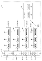
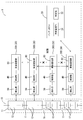
- FIG. 2 is a block diagram that embodies part of the battery monitoring system and the battery according to the first embodiment.
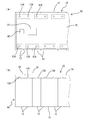
- FIG. 3A is a plan view partially and simply showing a configuration in which the battery monitoring device of the first embodiment is attached to the battery, and
- FIG. 3B is a front view thereof.
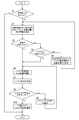
- FIG. 4 is a flowchart illustrating the flow of control executed by the battery ECU.
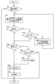
- FIG. 5 is a flowchart illustrating the flow of control executed by each battery monitoring device.
- FIG. 6 is an explanatory diagram conceptually illustrating a state of communication when all the battery monitoring devices are in a normal state in the battery monitoring system according to the first embodiment.
- FIG. 1 is a block diagram schematically illustrating an in-vehicle power supply system including the battery monitoring system according to the first embodiment.
- FIG. 2 is a block diagram that embodies part of the battery
- FIG. 7 is an explanatory diagram conceptually illustrating a state of communication when the lowest-level monitoring device is in an abnormal state in the battery monitoring system according to the first embodiment.
- FIG. 8 is an explanatory diagram conceptually illustrating a state of communication when the intermediate rank monitoring apparatus is in an abnormal state in the battery monitoring system according to the first embodiment.
- the battery monitoring device may have a substrate part that is assembled directly to the battery or indirectly through another member. At least the wireless communication unit may be mounted on the substrate unit.
- the substrate portion can be disposed near the battery, the size can be further reduced. Even if the board portion is arranged near the battery in this way, it is possible to transmit information to the outside wirelessly, so that it is difficult to complicate the routing design.
- the vehicle battery monitoring system may be configured to include a plurality of the battery monitoring devices and an external control device that receives information transmitted from any of the wireless communication units of the battery monitoring devices.
- the number of wires can be reliably reduced in a system that can transmit detection information (information indicating at least one of battery voltage and temperature) to the external control device by communication based on the detection result of the battery monitoring device. Can be realized.
- the battery monitoring system for vehicles may include three or more battery monitoring devices.
- any one device is determined as the highest-order monitoring device in the highest order, and any other device is determined as the lowest-order monitoring device in the lowest order.
- the intermediate-order monitoring device may be determined.
- the highest-level monitoring device wirelessly transmits wireless transmission data including detection information generated by the highest-level monitoring device with the next-order battery monitoring device lower than itself as the transmission destination May function as well.
- Each intermediate rank monitoring device adds detection information generated by itself to the given wireless transmission data when the wireless transmission data is given by wireless transmission from the battery monitoring device of the next higher rank than itself.
- the new wireless transmission data may be transmitted to a battery monitoring device of the next lower rank than itself.
- the wireless transmission data is given by wireless transmission from the battery monitoring device of the next higher rank than itself, the lowest-order monitoring device adds new detection information generated by itself to the given wireless transmission data. It is also possible to function to wirelessly transmit such wireless transmission data to the external control device.
- the information transmission order can be determined in a plurality of battery monitoring systems.
- the detection information generated by a plurality of battery monitoring devices is output to the outside, the detection information generated by each battery monitoring device can be collected in order starting from the highest-level monitoring device, and the collected data can be collected.
- Wireless transmission can be performed from the lowest-level monitoring device to the external control device.
- communication between the battery monitoring devices and communication from the lowest-order monitoring device to the external control device can be performed by wireless communication, so that the wiring reduction effect becomes extremely high.
- the detection information can be collected from the lowest level monitoring device and transmitted from the lowest level monitoring device to the external control device, it is compared with a configuration in which the external control device always communicates with all the battery monitoring devices. Thus, the burden on the external control device can be reduced.
- the external control device may function to wirelessly transmit command information for specifying a predetermined command to the lowest-level monitoring device.
- the lowest-level monitoring device displays the data including the command specified by the command information higher than itself.
- Each intermediate rank monitoring device receives a command specified by the command information when data including a command specified by the command information is given by wireless transmission from a battery monitoring device of the next lower rank than itself.
- the included data may function so as to be wirelessly transmitted with the battery monitoring device of the next higher rank than itself as the transmission destination.
- Each of the plurality of battery monitoring devices may function to perform control corresponding to the command specified by the command information when data including the command specified by the command information is received.
- the battery monitoring system capable of causing each of the plurality of battery monitoring devices to perform control according to the command from the external control device is reduced in the number of wires and the communication load of the external control device is reduced. realizable.
- the external control device may function to wirelessly transmit command information including a predetermined notification command to the lowest-level monitoring device.
- Each intermediate rank monitoring device transmits a battery monitoring device of the next higher rank than itself when data including a notification command is given by wireless transmission from the battery monitoring device of the next lower rank than itself. It may function to wirelessly transmit data including a notification command as a destination.
- the highest monitoring device uses the battery monitoring device of the next lower rank than itself as a transmission destination.
- the wireless transmission data including the detection information generated by the highest-level monitoring device may function to wirelessly transmit.
- Each of the intermediate rank monitoring devices is provided with the wireless transmission data when the data including the notification command is given and the wireless transmission data is given by the wireless transmission from the battery monitoring device of the next higher rank than itself. It is also possible to function to wirelessly transmit new wireless transmission data to which detection information generated by itself is added to a battery monitoring device of the next lower rank than itself.
- the lowest order monitoring device is provided with data including a notification command by wireless transmission from the external control device and wireless transmission data is provided by wireless transmission from the battery monitoring device of the next higher rank than itself, It may function to wirelessly transmit new wireless transmission data obtained by adding detection information generated by itself to given wireless transmission data to an external control device.
- a battery monitoring system capable of transmitting detection information (detection information indicating at least one of battery voltage and temperature) to each of the plurality of battery monitoring devices in response to a notification command from the external control device, This can be realized by reducing the number of wires and the communication load of the external control device.
- the detection unit of the battery monitoring device may be configured to detect voltage information that specifies a voltage between terminals of each battery cell in a battery formed by connecting a plurality of battery cells.
- the external control device may function to wirelessly transmit command information including a predetermined cell balance command to the lowest-level monitoring device.
- the lowest-order monitoring device transmits the data including the cell balance command to the next higher-order battery monitoring device. It may function to transmit wirelessly as a destination.
- Each of the intermediate rank monitoring devices when data including a cell balance command is given by wireless transmission from the next lower rank battery monitoring device, the next higher rank battery monitoring device. It may function to wirelessly transmit data including a cell balance command as a transmission destination.
- the plurality of battery cells are configured to equalize the voltage between the terminals of each of the battery cells based on the detection result by its own detection unit. It may function to control the charging or discharging.
- the battery monitoring system capable of causing each of the plurality of battery monitoring devices to perform cell balance control in response to a cell balance command from the external control device reduces the number of wires and reduces the communication burden of the external control device. It can be realized in a suppressed form.
- FIG. 1 schematically shows an in-vehicle power supply system 100.
- An in-vehicle power supply system 100 shown in FIG. 1 includes a battery 10, a battery monitoring system 1 that monitors the battery 10, and a power management ECU 120 (Electric Control Unit) that is provided so as to be communicable with the battery monitoring system 1.
- ECU 120 Electric Control Unit
- the battery 10 is, for example, a lithium ion battery including a plurality of battery cells 12, and uses, for example, electric power for driving an electric drive device (motor or the like) in a vehicle such as a hybrid vehicle or an electric vehicle (EV (Electric Vehicle)). Used as a power source for output.
- the battery 10 is charged by a power generator (not shown) mounted on the vehicle.
- the battery 10 includes one assembled battery 11 in which a plurality of battery cells 12 configured as lithium ion batteries are connected in series, and a predetermined number of assembled batteries 11 are arranged in series to form one stack 10A.
- the stack 10A is housed in a case.
- the battery 10 which can output a desired output voltage (for example, several hundred V) is comprised in the form where the stack 10A comprised in this way was connected in series.
- the battery monitoring system 1 includes a plurality of battery monitoring devices 30 and a battery ECU 20 as an external control device, and the plurality of battery monitoring devices 30 perform wireless communication with the battery ECU 20 (external control device). It has a configuration that can be performed. Further, each of the plurality of battery monitoring devices 30 is configured to be able to perform wireless communication with other battery monitoring devices 30.
- one battery monitoring device 30 is assigned to one assembled battery 11 constituting the battery 10.
- Each battery monitoring device 30 includes a detection unit 50 that detects the voltage and temperature of the assigned assembled battery 11, a control unit 40 that performs various controls such as control according to an external command, and other battery monitoring devices. 30 or a wireless communication unit 60 that performs wireless communication with the battery ECU 20.
- the control unit 40 shown in FIGS. 1 and 2 is configured by a microcomputer or other hardware circuit, and when at least the wireless communication unit 60 receives a command from the outside, it can perform control according to the command. If it is.
- the monitoring IC 32 is configured by integrating the control unit 40 and the detection / adjustment circuit unit 36. 2 conceptually shows the hardware configuration of the lowest-order monitoring device 30D among the plurality of battery monitoring devices 30, but the other battery monitoring devices 30 have the same hardware as the lowest-order monitoring device 30D.
- the hardware configuration is configured by a microcomputer or other hardware circuit, and when at least the wireless communication unit 60 receives a command from the outside, it can perform control according to the command. If it is.
- the monitoring IC 32 is configured by integrating the control unit 40 and the detection / adjustment circuit unit 36. 2 conceptually shows the hardware configuration of the lowest-order monitoring device 30D among the plurality of battery monitoring devices 30, but the other battery monitoring devices 30 have the same hardware as the lowest-order monitoring device 30D.
- the hardware configuration is configured
- the control unit 40 is configured as a microcomputer including a CPU, a ROM, a RAM, and the like.
- a predetermined notification command transmitted from the battery ECU 20 is directly or indirectly via another device.
- the wireless communication unit 60 receives the information, the temperature and voltage of the battery 10 are grasped based on a signal from the detection unit 50, and information on the temperature and voltage of the battery 10 is transmitted to the other battery monitoring device 30 or the battery ECU 20. Has a function of performing response processing.
- the control unit 40 is based on the detection result by the detection unit 50.
- the battery cell 12 has a function of performing a cell balance process for controlling charging or discharging of the plurality of battery cells 12 so as to make the voltage between the terminals of the battery cells 12 uniform.
- the detection unit 50 includes a detection / adjustment circuit unit 36 that functions as a voltage detection unit that detects a voltage at a predetermined position of the battery 10, and a temperature detection unit 38 that detects the temperature of the battery 10.
- the detection / adjustment circuit unit 36 detects voltage information specifying the voltage between the terminals of each battery cell 12 in the battery 10 to which the plurality of battery cells 12 are connected.
- the detection / adjustment circuit unit 36 includes a plurality of voltage signal lines 14 and a plurality of discharge units 16 respectively connected in parallel to the plurality of battery cells 12. In FIG. 2, some of the battery cells 12 (unit batteries) are omitted, and a circuit corresponding to the omitted battery cell 12 is also omitted.
- the plurality of voltage signal lines 14 are electrically connected to the inter-battery electrode portion 11C of the assembled battery 11 or the end electrode portions 11A and 11B of the assembled battery 11 in which the plurality of battery cells 12 are connected in series. It is connected to the.
- the electrode portion 11 ⁇ / b> A is an electrode portion at one end of the assembled battery 11, and is an electrode portion having the highest potential in the assembled battery 11.
- the electrode part 11 ⁇ / b> B is an electrode part at the other end of the assembled battery 11, and is an electrode part having the smallest potential in the assembled battery 11.
- the inter-battery electrode portion 11C is a portion in which the positive electrode on one side and the negative electrode on the other side are electrically connected between the batteries of the battery cells 12 (unit batteries) connected in series.
- the potential of the portion 11C increases as it approaches the electrode portion 11A.
- the plurality of voltage signal lines 14 are signal lines for inputting analog signals indicating the potentials of the electrode portions 11A, 11B, and 11C to the control unit 40.
- the control unit 40 can detect the terminal voltage of each battery cell 12 (unit battery) based on the analog voltage signal input via each voltage signal line 14.
- the control unit 40 includes an AD converter that converts each analog voltage signal input via each voltage signal line 14 into a digital signal. Since the control part 40 can grasp
- each voltage signal line 14 illustrates the current flowing from the battery cell 12 to the control unit 40 , but the current flowing from the battery cell 12 to the control unit 40 is limited by providing a current limiting resistor. Can do.
- a Zener diode (not shown) for clamping the voltage between the voltage signal lines at the time of overvoltage is connected in parallel with each battery cell 12 (specifically, the cathode is connected to the battery cell 12. It is desirable to connect the battery cell 12 in parallel with the positive electrode and the anode connected to the negative electrode.
- the temperature detection unit 38 is configured by, for example, a known temperature sensor, and is provided on the surface portion of the assembled battery 11 or the surface portion of the stack 10A shown in FIG. Arranged in contact or in close proximity without contact.
- the temperature detection unit 38 outputs a voltage value indicating the temperature at the arrangement position (that is, the surface temperature of the assembled battery 11 or the temperature near the surface) and inputs the voltage value to the control unit 40.
- the monitoring IC 32 including the control unit 40 and the detection / adjustment circuit unit 36 functions as a cell balance circuit that equalizes the respective voltages or capacities of the battery cells 12.
- the cell balance circuit is, for example, a circuit that eliminates the voltage variation of the plurality of battery cells 12 as much as possible and equalizes, for example, among the assembled batteries 11 assigned to the battery monitoring device 30.
- the battery cell 12 with the smallest potential difference (voltage between terminals) is detected, and the voltage of the other battery cell 12 is adjusted to the voltage of the detected battery cell 12 (that is, the battery cell 12 with the smallest voltage between terminals). It is conceivable to use a passive cell balance circuit that performs a discharge operation.
- the wireless communication unit 60 may be a circuit that performs wireless communication by a known wireless communication method, and the medium and frequency of the wireless signal are not limited. For example, radio waves can be suitably used for the mediation, but infrared rays or the like, or electromagnetic waves other than these may be used.
- the wireless communication unit 60 operates to receive a wireless signal when a wireless signal is transmitted from the wireless communication unit 60 of another battery monitoring device 30 or the wireless communication unit 24 of the battery ECU 20.
- the wireless communication unit 60 performs wireless transmission according to the control of the control unit 40 and transmits information related to the battery 10 to the wireless communication unit 60 of the other battery monitoring device 30 or the wireless communication unit 24 of the battery ECU 20. To work.
- the battery monitoring device 30 configured in this way is assembled to the battery 10 as shown in FIGS. 3A and 3B, for example.
- the battery monitoring device 30 has a substrate unit 70 configured as a known printed circuit board or the like, and the substrate unit 70 is directly fixed to the assembled battery 11 and integrated with the assembled battery 11. It is configured.
- the substrate unit 70 may be a rigid substrate or an FPC.
- a known bus bar substrate may be used.
- the substrate unit 70 may be a single layer substrate or a multilayer substrate.
- the monitoring IC 32 and the wireless communication unit 60 described above are mounted on the board unit 70 and integrated with the battery 10 via the board unit 70. In FIG. 3, wiring patterns and other electronic components formed on the substrate unit 70 are omitted.
- the substrate portion 70 is fixed to the terminal portions 12 ⁇ / b> A and 12 ⁇ / b> B (protrusions constituting the positive electrode or the negative electrode) of the battery cell 12 constituting the assembled battery 11, and the terminal portions 12 ⁇ / b> A and 12 ⁇ / b> B are electrically connected.
- the above-described voltage signal line 14 connected to is formed as a wiring pattern in the substrate portion 70.
- the terminal portion 12A is a protrusion that constitutes the positive electrode of the battery cell 12
- the terminal portion 12B is a protrusion that constitutes the negative electrode of the battery cell.
- the structure shown in FIG. 3 is an example of an attachment structure to the last, and is not limited to this example.
- substrate part 70 does not need to be directly fixed to the battery 10, and may be indirectly assembled
- the temperature sensor that constitutes the temperature detection unit 38 shown in FIGS. 1 and 2 may be mounted on the board unit 70 at a position in contact with the battery 10 or a position close to the battery 10, but not on the board unit 70.
- the battery 10 may be fixed directly or indirectly via another member.
- the temperature detection unit 38 and the substrate unit 70 may be electrically connected via a wiring unit or the like.
- the battery ECU 20 illustrated in FIG. 1 corresponds to an example of an external control device, and is configured as an electronic control device that can receive information transmitted from the wireless communication unit 60 of the battery monitoring device 30 and can perform various controls. It is configured. Battery ECU 20 can communicate with an external ECU (power management ECU 120 in FIG. 1) shown in FIG.
- the battery ECU 20 includes a wireless communication unit 24 that performs wireless communication and a determination unit 22 that performs various determinations such as a voltage abnormality determination.
- the battery ECU 20 includes a wireless communication unit 60 and a known microcomputer 21 (also referred to as a microcomputer 21), and the microcomputer 21 functions as the determination unit 22.
- the microcomputer 21 includes, for example, a CPU, a storage unit (ROM, RAM, etc.), an AD converter, and the like, and can perform various controls.
- the battery ECU 20 configured in this way is configured to be able to wirelessly communicate with each battery monitoring device 30.
- one of the battery monitoring devices 30 is set as a communication target, and at the time of reception, information wirelessly transmitted from the wireless communication unit 60 of the battery monitoring device 30 as a communication target is received. . In transmission, information is wirelessly transmitted to the wireless communication unit 60 of the battery monitoring device 30 to be communicated.
- the battery monitoring system 1 configured as described above can be arranged at a predetermined position in the vehicle in a form housed in a metal case together with the battery 10, for example.
- the case in which the battery 10 and the battery monitoring system 1 are housed in this way is preferably disposed in the vehicle away from noise generation sources such as a motor and an alternator that serve as a driving power source. It can arrange suitably in the lower position etc. of the seat provided in.
- the battery monitoring system 1 may be provided near the rear end of the vehicle.
- the battery monitoring system 1 may be provided near the front end of the vehicle.
- these examples are only preferable examples and can be arranged at various positions in the vehicle.
- the battery ECU 20 can perform wireless communication or wired communication with a power management ECU 120 provided outside, but the power management ECU 120 may be disposed outside the metal case described above. It may be arranged inside.
- the battery ECU 20 accommodated in the case and the power management ECU 120 disposed outside the case are connected to be communicable via a communication line such as a CAN communication line so that information can be transmitted and received between them. May be.
- the battery monitoring system 1 includes three or more battery monitoring devices 30 and a battery ECU 20 (external control) that receives information transmitted from any one of the plurality of battery monitoring devices 30. Device).
- a battery ECU 20 external control
- the battery ECU 20 and the lowest-order monitoring device 30D can directly perform wireless communication with each other without using other devices as in the example of FIG. 6 will be described as a representative example.
- the lowest-order monitoring device 30D may be configured to perform wireless communication with each other via the relay device.
- a plurality of battery monitoring devices 30 transmit information in series, and a basic order for transmitting information is determined in advance. Specifically, of the four battery monitoring devices 30, any one device is determined as the highest-order monitoring device 30A in the highest order (rank 1), and any other device is ranked in the lowest order (rank). 4) is defined as the lowest-order monitoring device 30D.
- the devices other than the highest-level monitoring device 30A and the lowest-level monitoring device 30D are defined as intermediate rank monitoring devices 30B and 30C.
- the intermediate rank monitoring device 30B is a battery monitoring device 30 of rank 2
- the intermediate ranking monitoring device 30C is a battery monitoring device of rank 3.
- Each battery monitoring device 30 is assigned a unique ID, and the assigned unique ID is stored in a storage unit (not shown). For example, a unique ID 1 is assigned to the highest order monitoring apparatus 30A, a unique ID 2 is assigned to the intermediate order monitoring apparatus 30B, a unique ID 3 is assigned to the intermediate order monitoring apparatus 30C, and the lowest order monitoring apparatus 30D is assigned. Is assigned a unique ID 4.
- the battery with the highest (smallest) rank Transmission is performed so that information is passed in order from the device with the highest priority, starting from the highest-order monitoring device 30A, which is the monitoring device 30.
- the highest-ranking monitoring device 30A of rank 1 receives the battery monitoring device 30 of the next rank lower than itself (that is, rank) in response to establishment of a predetermined transmission condition (for example, reception of command information including a notification command).
- Wireless transmission data including detection information generated by the highest-order monitoring device 30A is transmitted wirelessly with the second intermediate-order monitoring device 30B) as a transmission destination.
- Each of the intermediate rank monitoring devices 30B and 30C is generated by itself in the given wireless transmission data when the wireless transmission data is given by wireless transmission from the battery monitoring device 30 of the next higher rank than itself.
- the new wireless transmission data to which the detection information is added is transmitted to the battery monitoring device 30 of the next lower rank than itself.
- the intermediate rank monitoring device 30B includes wireless detection transmission information including the detection information of the highest-order monitoring device 30A by wireless transmission from the next higher-order battery monitoring device 30 (that is, the highest-order monitoring device 30A of rank 1).
- the new wireless transmission data obtained by adding the detection information generated by itself to the given wireless transmission data is used as the next lower battery monitoring device 30 (that is, the middle of the ranking 3). To the rank monitoring device 30C).
- the intermediate rank monitoring apparatus 30C performs the wireless transmission from the next higher rank battery monitoring apparatus 30 (that is, the intermediate rank monitoring apparatus 30B of rank 2) of the highest rank monitoring apparatus 30A and the intermediate rank monitoring apparatus 30B.
- wireless transmission data including detection information new wireless transmission data obtained by adding the detection information generated by itself to the given wireless transmission data is assigned to the battery monitoring device 30 of the next lower rank than itself ( In other words, the data is transmitted to the lowest-order monitoring device 30D) of rank 4.
- the lowest-order monitoring device 30D transmits the highest-order monitoring device 30A and the intermediate-order monitoring devices 30B and 30C by wireless transmission from the battery monitoring device 30 of the next higher rank than itself (that is, the intermediate-order monitoring device 30C of rank 3).
- new wireless transmission data obtained by adding the detection information generated by itself to the given wireless transmission data is wirelessly transmitted to the battery ECU 20 (external control device).
- data including detection information obtained by each of the plurality of battery monitoring devices 30 is transmitted from the lowest-order monitoring device 30D to the battery ECU 20 by wireless communication.
- the above operation is a basic operation when information from the plurality of battery monitoring devices 30 is transmitted to the battery ECU 20.
- the command information (command information for specifying a predetermined command) from the battery ECU 20 (external control device) when the battery monitoring system 30 is in a normal state in which no failure has occurred in these battery monitoring devices 30.
- information is transmitted as follows. First, the battery ECU 20 wirelessly transmits command information to the lowest order monitoring device 30D.
- the lowest-order monitoring device 30D is specified by the command information when data corresponding to the command information (data including the command specified by the command information) is given by wireless transmission from the battery ECU 20 (external control device). Is transmitted wirelessly with the next higher rank battery monitoring device 30 (that is, the intermediate ranking monitoring device 30C of ranking 3) as the transmission destination.
- the data including the command specified by the command information may be the command information itself or data obtained by processing the command information.
- the intermediate rank monitoring device 30C is given data including a command specified by the command information by wireless transmission from the battery monitoring device 30 of the next lower rank than itself (that is, the lowest-order monitoring device 30D of the rank 4).
- the data including the command specified by the command information is wirelessly transmitted to the battery monitoring device 30 of the next higher rank than itself (that is, the intermediate ranking monitoring device 30B of the ranking 2) as the transmission destination.
- the intermediate rank monitoring device 30B is given data including a command specified by the command information by wireless transmission from the battery monitoring device 30 of the next lower rank than itself (that is, the intermediate rank monitoring device 30C of the rank 3).
- the data including the command specified by the command information is wirelessly transmitted with the next higher-order battery monitoring device 30 (that is, the highest-level monitoring device 30A of the first rank) as the transmission destination.
- the battery monitoring device 30 corresponds to the command specified by the command information. Control.
- the battery ECU 20 performs control according to the flow shown in FIG. Specifically, the control of FIG. 4 is executed by the microcomputer 21 of the battery ECU 20, and the microcomputer 21 continuously repeats the control of FIG. 4 at short time intervals while the ignition switch is on.
- the battery ECU 20 determines whether or not there is a notification request from the power management ECU 120 after starting the control of FIG.
- the power management ECU 120 is configured to transmit information indicating a predetermined notification request (request to notify the state of the battery 10) to the battery ECU 20 at a predetermined timing. It is determined whether or not there is a notification request.
- the timing at which the notification request is transmitted from the power management ECU 120 to the battery ECU 20 may be, for example, immediately after the ignition switch is switched from the OFF state to the ON state, or any other predetermined diagnostic timing. It may be.
- step S2 the battery ECU 20 selects the lowest-ranked (highest-ranked) device among the plurality of battery monitoring devices 30 that are communication candidates.
- the command information including the unique ID of the target device and a predetermined notification command is transmitted to the target device.
- the notification command is a command for instructing the battery monitoring device 30 to transmit information on predetermined items.
- the communication candidates in step S2 are obtained by excluding the battery monitoring devices 30 (battery monitoring devices 30 determined to be faulty) excluded in step S5 from all the battery monitoring devices 30. For example, when the process of step S5 is not yet executed and all the battery monitoring devices 30 are in the normal state as shown in FIG.
- the battery ECU 20 In step S2, the lowest-order monitoring device 30D that is the lowest-ranked (highest-ranked) device among all the battery monitoring devices 30 is the target device, and the unique ID of the lowest-order monitoring device 30D is assigned to this target device.
- Command information including (unique ID 4) and a predetermined notification command is transmitted. For example, when each battery monitoring device 30 acquires information including its own unique ID, the battery monitoring device 30 performs processing according to the information, and when receiving information that does not include its own unique ID, Discard or ignore.
- the battery ECU 20 transmits the command information for any one of the battery monitoring devices 30 in step S2
- the battery ECU 20 determines whether communication is established with the battery monitoring device 30 that is the target. For example, when each battery monitoring device 30 receives command information including its own unique ID, the battery ECU 20 returns predetermined response information, and the battery ECU 20 monitors one of the battery monitoring devices in step S2.
- the command information including the unique ID of the battery monitoring device 30 is transmitted for the device 30 and it is determined that the response information corresponding to the transmission is received for a certain time after the transmission (step S3 If YES in step S6, the process of step S6 is performed. If it is determined that the message has not been received (NO in step S3), the process of step S4 is performed.
- step S2 when the battery ECU 20 transmits the command information including the unique ID (ID4) of the lowest-order monitoring device 30D with the lowest-order monitoring device 30D as a communication target in step S2, the battery ECU 20 receives the command information for a certain time after the transmission. If it is determined that the response information corresponding to the transmission has not been received, the process proceeds to step S4.
- ID4 the unique ID
- step S4 the battery ECU 20 communicates again with the battery monitoring device 30 that is the communication target at step S2 for a certain time or a certain number of times, and is communication established with the battery monitoring device 30? It is determined again whether or not. If the battery ECU 20 determines that the communication is established when the communication is performed again in step S4 (Yes in step S4), the process is performed in step S6, and the communication is established even if the communication is performed again in step S4. If it is determined that it has not been performed (No in step S4), the process of step S5 is performed.
- step S5 When performing the process of step S5, the battery ECU 20 determines that the battery monitoring device 30 communicated in the latest steps S2 and S4 is a failure and excludes it from the transmission candidates, and then performs the process of step S2 again.
- step S2 When the process of step S2 is performed after step S5, the command information is transmitted to the battery monitoring apparatus with the lowest rank among the new transmission candidates excluding the battery monitoring apparatus 30 excluded from the transmission candidates in step S5. For example, as shown in FIG. 7, when the lowest-order monitoring device 30D is out of order, communication is not established even if communication is performed with the lowest-order monitoring device 30D in the first step S2, and thus the process proceeds to step S4. Since communication is not established even in S4, the process proceeds to step S5.
- step S5 the plurality of battery monitoring devices 30 (the highest-level monitoring device 30A and the intermediate-level monitoring devices 30B and 30C) excluding the lowest-level monitoring device 30D become new transmission candidates.
- the command information including the unique ID of the intermediate rank monitoring apparatus 30C is transmitted to the intermediate rank monitoring apparatus 30C having the lowest (larger) rank among the transmission candidates.
- step S6 the process proceeds to step S6. In this case, it waits for information to be transmitted from the battery monitoring device 30 according to the command information. The processing after step S6 will be described later.
- Each battery monitoring device 30 performs control according to the flow shown in FIG.
- the control in FIG. 5 is executed by, for example, the control unit 40 of each battery monitoring device 30, and each control unit 40 continuously repeats the control in FIG. 4 at short time intervals while the ignition switch is on. .
- each battery monitoring device 30 After starting the control of FIG. 5, the control unit 40 determines whether or not the command information is received in step S21.
- the control unit 40 of each battery monitoring device 30 receives command information wirelessly transmitted from the battery ECU 20 or the battery monitoring device 30 with a lower rank, the process proceeds to Yes in step S21, and the command information is set as a transmission candidate. It transmits to the battery monitoring device 30 with the lowest rank among the battery monitoring devices 30 (higher transmission candidates) with higher rank than itself.
- the unique ID of the destination battery monitoring device 30 is included in the command information. For example, as shown in FIG.
- step S21 when all the battery monitoring devices 30 are in a normal state, when command information is transmitted from the battery ECU 20 to the lowest-order monitoring device 30D, the lowest-order monitoring device 30D that has received this command information. Becomes Yes in step S21, and the intermediate rank monitoring apparatus 30C having the lowest rank among the highest rank monitoring apparatus 30A and the intermediate rank monitoring apparatuses 30B and 30C, which are upper transmission candidates, is set as the transmission destination. Command information including the unique ID is transmitted. Alternatively, when the command information is transmitted from the lowest order monitoring device 30D to the intermediate rank monitoring device 30C, the intermediate rank monitoring device 30C that has received this command information becomes Yes in step S21 of the control in FIG.
- the command information including the unique ID of the intermediate rank monitoring apparatus 30B is transmitted to the intermediate rank monitoring apparatus 30B having the lowest rank among the highest rank monitoring apparatus 30A and the intermediate rank monitoring apparatus 30B.
- the intermediate rank monitoring device 30B that has received this command information becomes Yes in step S21 of the control in FIG.
- Command information including the unique ID of the highest-level monitoring device 30A is transmitted to the candidate, the highest-level monitoring device 30A.
- the command information wirelessly transmitted from the battery ECU 20 to any one of the battery monitoring devices 30 is thus transmitted to the upper side.
- the battery monitoring device 30 performs the process of step S22 and returns response information to the transmission source.
- step S22 When each battery monitoring device 30 transmits command information for any one of the higher-level battery monitoring devices 30 in step S22, communication is performed with the target battery monitoring device 30 in step S23. It is determined whether or not it is established.
- step S22 when the battery monitoring device 30 targets any one of the battery monitoring devices 30 and transmits the command information including the unique ID of the battery monitoring device 30, the battery monitoring device 30 transmits the command information for a certain time after the transmission. If it is determined that the response information corresponding to is not received (No in Step S23), the process of Step S24 is performed. If it is determined that the response information is received (Yes in Step S23), the process of Step S26 is performed. I do.
- step S22 If it is determined that the response information corresponding to the transmission has not been received, the process proceeds to step S24.
- step S24 the battery monitoring device 30 communicates again with the battery monitoring device 30 that is the communication target in step S22 for a certain time or a certain number of times, and the communication with the battery monitoring device 30 is established. It is determined again whether or not. If the battery monitoring device 30 determines that the communication is established when the communication is performed again in step S24 (Yes in step S24), the battery monitoring device 30 performs the process of step S26, and performs the communication again in step S24. If it is determined that communication has not been established (No in step S24), the process of step S25 is performed.
- the battery monitoring apparatus 30 determines that the battery monitoring apparatus 30 communicated in the most recent steps S22 and S24 is a failure and excludes it from the upper transmission candidates, and then performs the process of step S22 again. Do.
- the battery monitoring apparatus 30 with the lowest rank among the new upper transmission candidates excluding the battery monitoring apparatus 30 excluded from the upper transmission candidates in step S25 is set as the transmission destination.
- Command information including the unique ID of the battery monitoring device 30 is transmitted. For example, if the lowest order monitoring device 30D performs the control shown in FIG. 5 when the intermediate rank monitoring device 30C is out of order as shown in FIG.
- step S24 the process proceeds to step S24. Since communication is not established even in step S24, the process proceeds to step S25.
- step S25 among the battery monitoring devices 30 with higher (smaller) rank than the lowest-order monitoring device 30D, a plurality of battery monitoring devices 30 (the highest-level monitoring device 30A, the intermediate ranking) excluding the intermediate ranking monitoring device 30C.
- the monitoring device 30B becomes a new higher-order transmission candidate, and in the subsequent step S22, the unique ID of the intermediate-order monitoring device 30B with the lowest-order (larger) intermediate-order monitoring device 30B among the new higher-order transmission candidates as a transmission target.
- the command information including is transmitted.
- the intermediate rank monitoring apparatus 30C is skipped from the lowest rank monitoring apparatus 30D, and the command information is wirelessly transmitted to the intermediate rank monitoring apparatus 30B.
- the top-level monitoring device 30A omits steps S22 to S25 when performing the control of FIG. Further, as a result of the exclusion process performed by the battery monitoring device 30 in step S25, if there is no higher transmission candidate, the process may proceed to step S26.
- Each battery monitoring device 30 determines whether or not a predetermined notification command is included in the received command information (command information including its own unique ID) when performing the process of step S26.
- the voltage and temperature are detected in step S29.
- the control unit 40 of the battery monitoring device 30 that performs the process of step S26 assigns the battery monitoring device 30 based on the analog voltage value input via each voltage signal line 14 illustrated in FIG.
- the voltage between the terminals of each battery cell 12 of the assembled battery 11 is calculated.
- the temperature of the battery 10 (specifically, the temperature of the assigned assembled battery 11) is grasped based on the detection value input from the temperature detection unit 38.
- the control unit 40 detects the voltage between the terminals of each battery cell 12 and the temperature of the assembled battery 11 in step S29, and then wirelessly transmits the information in step S30. For example, when the highest-level monitoring device 30A executes the process of step S30 in the control of FIG. 5, the highest-level monitoring device 30A becomes a transmission starting point, and the lower-level battery monitoring device 30 that gives command information to the highest-level monitoring device 30A.
- the wireless transmission data including the information (detection information) detected in step S29 is transmitted. If any of the battery monitoring devices 30 performs the process of step S25 and there is no higher transmission candidate and the process proceeds to step S26, the battery monitoring device 30 becomes a transmission start point, and a command is sent to the battery monitoring device 30.
- the wireless transmission data including the information (detection information) detected in step S29 is transmitted to the lower battery monitoring device 30 that has given the information.
- the device that has received the command information from another battery monitoring device 30 executes the process of step S30 in the control of FIG.
- the wireless monitoring data is received from the host battery monitoring device 30 (the device determined to have established communication in step S23 or step S24) to which the battery monitoring device 30 has given the command information in the control of FIG.
- the wireless transmission data is added with the information (detection information) detected by itself in step S29 to generate new wireless transmission data, and the new wireless transmission data is subordinate to the command information given to the battery monitoring device 30.
- Wireless transmission to the battery monitoring device 30 is performed.
- the device that has received the command information from the battery ECU 20 executes the process of step S30 in the control of FIG. 5, and the battery monitoring device 30 receives the command information in the control of FIG.
- the wireless transmission data from the battery monitoring device 30 (the device determined to have established communication in step S23 or step S24)
- the information (detection information) detected by itself in step S29 is received for this wireless transmission data.
- new wireless transmission data is generated, and the new wireless transmission data is wirelessly transmitted to the battery ECU 20.
- step S3 or step S4 the battery ECU 20 waits for a certain period of time and then responds to the transmitted command information (each battery monitoring device 30 performs the process of step S29. Receive voltage and temperature information). Specifically, wireless transmission data (data transmitted by the battery monitoring device 30 in step S30) wirelessly transmitted from the battery monitoring device 30 determined to have established communication in step S3 or step S4 is received.
- Battery ECU20 performs the process of step S7 after receiving wireless transmission data from the battery monitoring apparatus 30 by the process of step S6, and determines the state of the battery 10 based on the received wireless transmission data.
- the determination unit 22 that is, the microcomputer 21 calculates the voltage (battery voltage) of the entire battery 10 based on the wireless transmission data (data including detection information of the plurality of battery monitoring devices 30).
- the voltage of the whole battery 10 can be calculated by integrating the whole voltage of each assembled battery 11 to which each battery monitoring device 30 is assigned.
- the voltage across the battery 10 can be calculated by integrating the inter-terminal voltages of all the battery cells 12.
- the determination unit 22 determines whether or not the battery 10 overall voltage (battery voltage) calculated in this way is an overcharged state exceeding a predetermined first threshold value, and the battery voltage is lower than the first threshold value. It is determined whether or not the overdischarge state is less than the second threshold value. Furthermore, based on the temperature information obtained from each battery monitoring device 30, it is determined whether or not the temperature of any assembled battery 11 is in an overheated state exceeding a predetermined temperature threshold. As described above, the determination unit 22 determines whether or not the voltage and temperature of the battery 10 are abnormal based on the detection information received by the wireless communication unit 24.
- the battery ECU 20 determines whether or not the variation in the voltage between the terminals of the plurality of battery cells 12 is within a certain value in each assembled battery 11 (step S8). For example, the inter-terminal voltage of the battery cell 12 having the highest inter-terminal voltage in any of the assembled batteries 11 based on the wireless transmission data (data including detection information of the plurality of battery monitoring apparatuses 30) received from the battery monitoring apparatus 30 And the difference between the terminal voltage of the battery cell 12 having the smallest terminal voltage exceeds a predetermined value, and if the difference exceeds a predetermined value in any of the assembled batteries 11 (Yes in step S8) In step S9, command information including a cell balance command for commanding the battery monitoring device 30 or all the battery monitoring devices 30 to which the assembled battery 11 is assigned is transmitted.
- command information including the cell balance command is given to the battery monitoring device 30 determined to have established communication in step S3 or step S4.
- Wireless transmission Since each battery monitoring device 30 repeatedly performs the control of FIG. 5, the command information wirelessly transmitted in this way follows the same flow as the above-described command information (command information including a notification command). Is transmitted to the device 30.
- each battery monitoring device 30 receives the command information including the notification command, it transmits the command information to the upper side in step S22, and then executes the processes of steps S29 and S30.
- the command information including the command is received, the command information is transmitted to the upper side in step S22, and then the processes of steps S27 and S28 are executed.
- the cell balance command is a command for causing the battery monitoring device 30 to execute cell balance processing, and is, for example, a command specified by predetermined information.
- each battery monitoring device 30 determines whether or not a cell balance command has been issued in step S ⁇ b> 27 in the process of FIG. 5 that is repeated at short time intervals, and the cell balance command is included in the received command information. If it is included (No in step S26, Yes in step S27), cell balance processing is performed in step S28. Specifically, the battery monitoring device 30 to which the cell balance command is given matches the output voltage of the battery cell 12 having the lowest output voltage among the plurality of battery cells 12 constituting the assembled battery 11 assigned to itself. In addition, the detection / adjustment circuit unit 36 is caused to perform the operation of discharging the remaining battery cells 12.
- a discharge unit 16 for discharging each battery cell 12 is connected to the detection / adjustment circuit unit 36, and the control unit 40 controls the operation of the discharge unit 16 to control the assigned assembled battery 11.
- the voltage between terminals of all the battery cells 12 is equalized so as to be approximately the same.
- step S28 of FIG. 5 the battery monitoring device 30 performs the process of step S29 described above again, and the terminals of the battery cells 12 after the cell balancing process in the assigned assembled battery 11 are performed. The inter-voltage and the temperature of the assembled battery 11 are detected. Then, the process of step S30 is performed, and the information detected in step S29 is transmitted as wireless transmission data. After the cell balance processing is performed in each battery monitoring device 30 in this way, the detection information generated by each battery monitoring device 30 in step S29 is collected into wireless transmission data and wirelessly transmitted to the battery ECU 20. Become.
- the battery ECU 20 waits for a certain period of time in step S6 when the cell balance command is transmitted in step S9 of FIG. 4, and when the wireless transmission data is received again from the battery monitoring device 30, the process after step S7 is performed. Do it again.
- step S10 The battery state is transmitted to the external ECU (power management ECU 120). Specifically, based on the determination result in the most recent step S7, information indicating whether or not the battery voltage is in an overcharged state exceeding a predetermined first threshold, and an overdischarge state in which the battery voltage is less than the second threshold Information indicating whether or not the battery pack 11 is in an overheated state in which the temperature of any one of the assembled batteries 11 exceeds a predetermined temperature threshold is transmitted to the power management ECU 120. In addition to this, various information such as the SOC, SOH, and internal resistance of the battery 10 may be transmitted.
- the battery monitoring device 30 can transmit the detection information (information indicating at least one of the voltage and the temperature of the battery 10) based on the detection result of the detection unit 50 to the other battery monitoring device 30, the other battery monitoring is performed. Detection information can be transmitted using the device 30. In addition, the characteristic information transmission using the other battery monitoring device 30 can be realized by wireless communication in this way, so that the number of wirings can be effectively reduced.
- the battery monitoring device 30 has a substrate unit 70 that is directly or indirectly assembled to the battery 10 via another member. At least the wireless communication unit 60 is mounted on the substrate unit 70.
- the substrate portion 70 can be disposed near the battery 10, further downsizing can be achieved.
- substrate part 70 is arrange
- transmission of the information to the exterior can be performed by radio
- the battery monitoring system 1 includes a plurality of battery monitoring devices 30 and a battery ECU 20 (external control device) that receives information transmitted from any of the wireless communication units 60 of the battery monitoring devices 30. ing.
- a system that can transmit detection information (information indicating at least one of the voltage and temperature of the battery 10) based on the detection result in the battery monitoring device 30 to the battery ECU 20 (external control device) by communication. This can be realized with a reduced number of wires.
- the battery monitoring system 1 is configured to include three or more battery monitoring devices 30.
- any one device is defined as the highest-order monitoring device 30A, and any other device is defined as the lowest-order monitoring device 30D.
- the devices other than the upper monitoring device 30A and the lowest monitoring device 30D are defined as intermediate rank monitoring devices 30B and 30C.
- the highest-level monitoring device 30A includes wireless transmission data including detection information generated by the highest-level monitoring device 30A with the next-order battery monitoring device 30 lower than itself as a transmission destination in response to establishment of a predetermined transmission condition. Function to wirelessly transmit.
- Each of the intermediate rank monitoring devices 30B and 30C is generated by itself in the given wireless transmission data when the wireless transmission data is given by wireless transmission from the battery monitoring device 30 of the next higher rank than itself. It functions to transmit new wireless transmission data to which the detection information is added to the battery monitoring device 30 of the next lower rank than itself.
- the lowest-order monitoring device 30D adds detection information generated by itself to the given wireless transmission data. It functions to wirelessly transmit the new wireless transmission data to the battery ECU 20 (external control device).
- the information transmission order can be determined in the plurality of battery monitoring systems 1.
- the detection information generated by the plurality of battery monitoring devices 30 is output to the outside, the detection information generated by each battery monitoring device 30 can be collected in order starting from the highest-level monitoring device 30A.
- the data can be wirelessly transmitted from the lowest-order monitoring device 30D to the battery ECU 20 (external control device).
- the communication between the battery monitoring devices 30 and the communication from the lowest-order monitoring device 30D to the battery ECU 20 (external control device) can be performed by wireless communication, so the wiring reduction effect is extremely high. .
- the battery ECU 20 (external control device) always has all the battery monitoring devices. Compared with a configuration in which communication is performed with 30, it is possible to reduce the burden on the battery ECU 20 (external control device).
- the battery ECU 20 wirelessly transmits command information for specifying a predetermined command to the lowest-order monitoring device 30D. Function.
- the lowest order monitoring device 30D receives data (command information itself or data obtained by processing the command information) including the command specified by the command information by wireless transmission from the battery ECU 20 (external control device), It functions to wirelessly transmit data including the command specified by the information, with the next higher battery monitoring device 30 (intermediate ranking monitoring device 30C) as the transmission destination.
- Each of the intermediate rank monitoring devices 30B and 30C is specified by the command information when data including a command specified by the command information is given by wireless transmission from the battery monitoring device 30 of the next lower rank than itself. It functions to wirelessly transmit the data including the command to be transmitted to the battery monitoring device 30 of the next higher rank than itself as the transmission destination.
- Each of the plurality of battery monitoring devices 30 functions to perform control corresponding to the command specified by the command information when data including the command specified by the command information is received.
- the battery monitoring system 1 capable of causing each of the plurality of battery monitoring devices 30 to perform control in accordance with a command from the battery ECU 20 (external control device) has a reduced number of wires and the battery ECU 20 (external control). This can be realized with a reduced communication burden on the device.
- the battery ECU 20 (external control device) functions to wirelessly transmit command information including a predetermined notification command to the lowest-order monitoring device 30D.
- the battery ECU 20 external control device
- Each of the intermediate rank monitoring devices 30B and 30C receives the battery including the notification command by wireless transmission from the battery monitoring device 30 of the next lower rank than itself. It functions to wirelessly transmit data including a notification command with the monitoring device 30 as a transmission destination.
- the highest-level monitoring device 30A It functions to wirelessly transmit wireless transmission data including detection information generated by the highest-order monitoring device 30A with the battery monitoring device 30 (intermediate ranking monitoring device 30B) as the transmission destination.
- Each of the intermediate rank monitoring devices 30B and 30C is given when data including a notification command is given and wireless transmission data is given by wireless transmission from the battery monitoring device 30 of the next higher rank than itself. It functions to wirelessly transmit new wireless transmission data obtained by adding detection information generated by itself to the wireless transmission data to the battery monitoring device 30 of the next lower rank than itself.
- the lowest-order monitoring device 30D is given data including a notification command by wireless transmission from the battery ECU 20 (external control device), and from the next higher-order battery monitoring device 30 (intermediate ranking monitoring device 30C).
- wireless transmission data is given by wireless transmission
- new wireless transmission data obtained by adding detection information generated by itself to the given wireless transmission data is wirelessly transmitted to the battery ECU 20 (external control device).
- detection information (detection information indicating at least one of the voltage and the temperature of the battery 10) is transmitted to each of the plurality of battery monitoring devices 30 in response to a notification command from the battery ECU 20 (external control device).
- the obtained battery monitoring system 1 can be realized with a reduced number of wires and a reduced communication burden on the battery ECU 20 (external control device).
- the detection unit 50 of the battery monitoring device 30 is configured to detect voltage information that specifies the voltage between terminals of each battery cell 12 in the battery 10 to which a plurality of battery cells 12 are connected.
- the battery ECU 20 (external control device) functions to wirelessly transmit command information including a predetermined cell balance command to the lowest level monitoring device 30D when the lowest level monitoring device 30D is in a communicable state.
- the lowest-order monitoring device 30D converts the data including the cell balance command to the next higher rank than itself. It functions to wirelessly transmit the battery monitoring device 30 (intermediate rank monitoring device 30C) as a transmission destination.
- Each of the intermediate rank monitoring devices 30B and 30C has the next higher rank than itself when the data including the cell balance command is given by wireless transmission from the battery monitoring device 30 of the next lower rank than itself. It functions to wirelessly transmit data including a cell balance command with the battery monitoring device 30 as a transmission destination.
- the plurality of battery monitoring devices 30 receives data including a cell balance command, the plurality of battery monitoring devices 30 are configured to equalize the inter-terminal voltage of each battery cell 12 based on the detection result by its own detection unit 50. It functions to control charging or discharging of the battery cell 12.
- the battery monitoring system 1 that can cause each of the plurality of battery monitoring devices 30 to perform cell balance control in response to a cell balance command from the battery ECU 20 (external control device) reduces the number of wires and This can be realized with a reduced communication burden on the ECU 20 (external control device).
- each battery cell 12 is configured to be capable of being discharged individually, and the example in which the voltage between terminals is uniformed by the discharge control of each battery cell 12 is shown. The voltage between the terminals may be made uniform by charge control or discharge control of the battery cell 12.
- one battery monitoring device 30 is assigned to one assembled battery 11, but one battery monitoring device 30 may be assigned to a plurality of assembled batteries 11. Alternatively, one assembled battery 11 may be divided into a plurality of areas, and the battery monitoring device 30 may be assigned to each area.
- Example 1 although the board
- the battery ECU 20 is illustrated as an example of the external control device.
- the battery ECU 20 is not limited to the battery ECU 20 as long as it is an in-vehicle electronic control device provided outside the battery monitoring device 30.
- the example in which the battery monitoring device 30 is assigned to the assembled battery 11 in which a plurality of battery cells 12 are aggregated is shown. May be assembled.
- Example 1 although each battery monitoring apparatus 30 demonstrated control of FIG. 5, the example which detects the voltage between the terminals of each battery cell 12 which comprises the assembled battery 11, and the temperature of the assembled battery 11 in step S29 was demonstrated. Alternatively, the overall voltage, internal resistance, capacity, and deterioration degree of the assembled battery 11 or the internal resistance, capacity, and deterioration degree of each battery cell 12 may be calculated, and these pieces of information may be wirelessly transmitted in step S30.
- the command information including the cell balance command is transmitted in step S9 and the cell ballast processing is performed in all the battery monitoring devices 30.
- the cell balance command may be given only to the battery monitoring device 30 assigned to the assembled battery 11 in which the variation in the inter-terminal voltage of the battery cell 12 is not within a certain value.
- the battery ECU 20 transmits command information that associates a unique ID that designates the battery monitoring device 30 with a cell balance command, and the battery monitoring device 30 side associates a cell balance command that is associated with its own unique ID. Cell balance processing may be performed.
- wireless communication may be performed indirectly via a relay device.
- the command information wirelessly transmitted from the battery ECU 20 may be temporarily received by the relay device, and the command information transmitted from the relay device may be received by any of the battery monitoring devices 30.
- the wireless transmission data wirelessly transmitted from any one of the battery monitoring devices 30 may be temporarily received by the relay device, and the wireless transmission data transmitted from the relay device may be received by the battery ECU 20.
- both direct wireless communication and indirect wireless communication via a relay device may be performed as wireless communication between the battery ECU 20 and the battery monitoring device 30.
Abstract
The present invention implements a vehicle battery monitoring device and vehicle battery monitoring system which are capable of helping to reduce the number of wirings and transmitting information by using a characteristic transmission path. The battery monitoring device (30) has: a detection unit (50) which detects at least any one of a voltage at a prescribed point of the battery (10) or a temperature of the battery (10); and a wireless communication unit (60) which, through a wireless communication scheme, transmits the detection information, representing at least any one of the voltage or temperature of the battery (10), to another battery monitoring device (30) provided at least in a vehicle, on the basis of the detection result from the detection unit (50).
Description
本発明は、車両用のバッテリ監視装置及び車両用のバッテリ監視システムに関するものである。
The present invention relates to a vehicle battery monitoring device and a vehicle battery monitoring system.
従来、複数のセルによって構成されたバッテリの各セルをバッテリ監視装置によって監視する技術が提供されている。例えば、特許文献1で開示されるバッテリ監視装置は、複数の組電池のそれぞれに対応してサテライト基板が設けられ、サテライト基板には対応する組電池の各セル電圧を監視する監視ICが実装されている。そして、複数のサテライト基板が連結配線によって接続され、いずれかのサテライト基板が接続配線によってメイン基板に接続されている。
Conventionally, a technique for monitoring each cell of a battery composed of a plurality of cells by a battery monitoring device has been provided. For example, the battery monitoring device disclosed in Patent Document 1 is provided with a satellite substrate corresponding to each of a plurality of assembled batteries, and a monitoring IC that monitors each cell voltage of the corresponding assembled battery is mounted on the satellite substrate. ing. A plurality of satellite substrates are connected by connecting wires, and any one of the satellite substrates is connected to the main substrate by connection wires.
しかし、特許文献1で開示されるバッテリ監視装置は、サテライト基板同士を連結する連結配線やサテライト基板とメイン基板とを連結する接続配線が必須となるため、配線数が多くなってしまい、重量やサイズの増加を招くという問題がある。また、配線数が多くなると、配索設計の複雑化を招くという問題もある。
However, the battery monitoring device disclosed in Patent Document 1 requires a connection wiring for connecting the satellite boards and a connection wiring for connecting the satellite board and the main board, which increases the number of wirings, There is a problem of increasing the size. Further, when the number of wirings increases, there is a problem that the wiring design is complicated.
本発明は、本発明は上述した事情に基づいてなされたものであり、配線数の低減を図ることができ、且つ特徴的な伝送経路を利用して情報の伝送を行い得る車両用のバッテリ監視装置又は車両用のバッテリ監視システムを提供することを目的とするものである。
The present invention has been made based on the above-described circumstances, and can monitor a vehicle battery that can reduce the number of wires and can transmit information using a characteristic transmission path. An object of the present invention is to provide a battery monitoring system for an apparatus or a vehicle.
本発明の一例であるバッテリ監視装置は、
車両内に設けられたバッテリを監視するバッテリ監視装置であって、
前記バッテリの所定位置の電圧又は前記バッテリの温度の少なくともいずれかを検出する検出部と、
前記検出部による検出結果に基づき、前記バッテリの電圧又は温度の少なくともいずれかを示す検出情報を、少なくとも前記車両内に設けられた他のバッテリ監視装置に無線通信方式で送信する無線通信部と、
を有する。 A battery monitoring apparatus as an example of the present invention is:
A battery monitoring device for monitoring a battery provided in a vehicle,
A detection unit that detects at least one of a voltage at a predetermined position of the battery or a temperature of the battery;
A wireless communication unit that transmits detection information indicating at least one of the voltage or temperature of the battery based on a detection result by the detection unit to at least another battery monitoring device provided in the vehicle by a wireless communication method;
Have
上記バッテリ監視装置は、検出部の検出結果に基づく検出情報(バッテリの電圧又は温度の少なくともいずれかを示す情報)を他のバッテリ監視装置に伝送することができるため、他のバッテリ監視装置を利用した検出情報の伝送が可能となる。しかも、このように他のバッテリ監視装置を利用した特徴的な情報伝送を無線通信によって実現することができるため、配線数を効果的に減らすことができる。
Since the battery monitoring device can transmit detection information (information indicating at least one of battery voltage and temperature) based on the detection result of the detection unit to another battery monitoring device, the other battery monitoring device is used. The detected information can be transmitted. In addition, characteristic information transmission using other battery monitoring devices can be realized by wireless communication in this way, so that the number of wires can be effectively reduced.
バッテリ監視装置は、バッテリに対して直接又は他部材を介して間接的に組み付けられる基板部を有していてもよい。そして、少なくとも無線通信部が基板部に実装されていてもよい。
The battery monitoring device may have a substrate part that is assembled directly to the battery or indirectly through another member. At least the wireless communication unit may be mounted on the substrate unit.
上記構成によれば、バッテリの近くに基板部を配置することができるため、より一層の小型化が図られる。このようにバッテリの近くに基板部を配置しても、外部への情報の伝送を無線によって行うことができるため配索設計の複雑化を招きにくい。
According to the above configuration, since the substrate portion can be disposed near the battery, the size can be further reduced. Even if the board portion is arranged near the battery in this way, it is possible to transmit information to the outside wirelessly, so that it is difficult to complicate the routing design.
上記バッテリ監視装置の複数と、複数のバッテリ監視装置のいずれかの無線通信部から送信された情報を受信する外部制御装置とを含む構成で、車両用のバッテリ監視システムを構成してもよい。
The vehicle battery monitoring system may be configured to include a plurality of the battery monitoring devices and an external control device that receives information transmitted from any of the wireless communication units of the battery monitoring devices.
上記構成によれば、バッテリ監視装置での検出結果に基づく検出情報(バッテリの電圧又は温度の少なくともいずれかを示す情報)を通信によって外部制御装置に伝送し得るシステムを、配線数を確実に低減した形で実現できる。
According to the above configuration, the number of wires can be reliably reduced in a system that can transmit detection information (information indicating at least one of battery voltage and temperature) to the external control device by communication based on the detection result of the battery monitoring device. Can be realized.
車両用のバッテリ監視システムは、3以上の複数のバッテリ監視装置を含むように構成してもよい。複数のバッテリ監視装置のうち、いずれか一の装置が最上位の順位の最上位監視装置と定められ、いずれか他の装置が最下位の順位の最下位監視装置と定められ、最上位監視装置及び最下位監視装置以外が中間順位監視装置と定められていてもよい。最上位監視装置は、所定の送信条件の成立に応じて、自身よりも低い次の順位のバッテリ監視装置を送信先として当該最上位監視装置で生成された検出情報を含む無線送信データを無線送信するように機能してもよい。各々の中間順位監視装置は、自身よりも高い次の順位のバッテリ監視装置からの無線送信によって無線送信データが与えられた場合に、与えられた無線送信データに自身で生成された検出情報を加えた新たな無線送信データを自身よりも低い次の順位のバッテリ監視装置に送信するように機能してもよい。最下位監視装置は、自身よりも高い次の順位のバッテリ監視装置からの無線送信によって無線送信データが与えられた場合に、与えられた無線送信データに自身で生成された検出情報を加えた新たな無線送信データを外部制御装置に向けて無線送信するように機能してもよい。
The battery monitoring system for vehicles may include three or more battery monitoring devices. Among the plurality of battery monitoring devices, any one device is determined as the highest-order monitoring device in the highest order, and any other device is determined as the lowest-order monitoring device in the lowest order. Other than the lowest-order monitoring device, the intermediate-order monitoring device may be determined. In response to the establishment of a predetermined transmission condition, the highest-level monitoring device wirelessly transmits wireless transmission data including detection information generated by the highest-level monitoring device with the next-order battery monitoring device lower than itself as the transmission destination May function as well. Each intermediate rank monitoring device adds detection information generated by itself to the given wireless transmission data when the wireless transmission data is given by wireless transmission from the battery monitoring device of the next higher rank than itself. The new wireless transmission data may be transmitted to a battery monitoring device of the next lower rank than itself. When the wireless transmission data is given by wireless transmission from the battery monitoring device of the next higher rank than itself, the lowest-order monitoring device adds new detection information generated by itself to the given wireless transmission data. It is also possible to function to wirelessly transmit such wireless transmission data to the external control device.
このような車両用のバッテリ監視システムによれば、複数のバッテリ監視システムにおいて情報の伝送順序を定めることができる。そして、複数のバッテリ監視装置で生成された検出情報を外部に出力する場合、最上位監視装置を起点として各バッテリ監視装置で生成された検出情報を順番に集めることができ、集められたデータを最下位監視装置から外部制御装置に向けて無線送信することができる。このような方式を採用すると、バッテリ監視装置間の通信及び最下位監視装置から外部制御装置への通信を無線通信で行うことができるため、配線の削減効果が極めて高くなる。しかも、最下位監視装置に検出情報を集めた上で最下位監視装置から外部制御装置へ伝送することができるため、外部制御装置が常に全てのバッテリ監視装置と通信を行うような構成と比較して外部制御装置の負担を低減することができる。
According to such a vehicle battery monitoring system, the information transmission order can be determined in a plurality of battery monitoring systems. When the detection information generated by a plurality of battery monitoring devices is output to the outside, the detection information generated by each battery monitoring device can be collected in order starting from the highest-level monitoring device, and the collected data can be collected. Wireless transmission can be performed from the lowest-level monitoring device to the external control device. When such a method is adopted, communication between the battery monitoring devices and communication from the lowest-order monitoring device to the external control device can be performed by wireless communication, so that the wiring reduction effect becomes extremely high. Moreover, since the detection information can be collected from the lowest level monitoring device and transmitted from the lowest level monitoring device to the external control device, it is compared with a configuration in which the external control device always communicates with all the battery monitoring devices. Thus, the burden on the external control device can be reduced.
車両用のバッテリ監視システムにおいて、外部制御装置は、所定の指令が特定される指令情報を最下位監視装置に対し無線送信するように機能してもよい。最下位監視装置は、外部制御装置からの無線送信によって指令情報で特定される指令を含んだデータが与えられた場合に、指令情報で特定される指令を含んだデータを、自身よりも高い次の順位のバッテリ監視装置を送信先として無線送信するように機能してもよい。各々の中間順位監視装置は、自身よりも低い次の順位のバッテリ監視装置からの無線送信によって指令情報で特定される指令を含んだデータが与えられた場合に、指令情報で特定される指令を含んだデータを、自身よりも高い次の順位のバッテリ監視装置を送信先として無線送信するように機能してもよい。複数のバッテリ監視装置の各々は、指令情報で特定される指令を含んだデータを受信した場合に、指令情報で特定される指令に対応する制御を行うように機能してもよい。
In the vehicle battery monitoring system, the external control device may function to wirelessly transmit command information for specifying a predetermined command to the lowest-level monitoring device. When the data including the command specified by the command information is given by wireless transmission from the external control device, the lowest-level monitoring device displays the data including the command specified by the command information higher than itself. It is also possible to function to wirelessly transmit the battery monitoring devices of the ranks as destinations. Each intermediate rank monitoring device receives a command specified by the command information when data including a command specified by the command information is given by wireless transmission from a battery monitoring device of the next lower rank than itself. The included data may function so as to be wirelessly transmitted with the battery monitoring device of the next higher rank than itself as the transmission destination. Each of the plurality of battery monitoring devices may function to perform control corresponding to the command specified by the command information when data including the command specified by the command information is received.
上記構成によれば、複数のバッテリ監視装置のそれぞれに外部制御装置からの指令に応じた制御を行わせ得るバッテリ監視システムを、配線数を抑え、且つ外部制御装置の通信負担を抑えた形で実現できる。
According to the above configuration, the battery monitoring system capable of causing each of the plurality of battery monitoring devices to perform control according to the command from the external control device is reduced in the number of wires and the communication load of the external control device is reduced. realizable.
車両用のバッテリ監視システムにおいて、外部制御装置は、所定の通知指令を含む指令情報を最下位監視装置に対し無線送信するように機能してもよい。各々の中間順位監視装置は、自身よりも低い次の順位のバッテリ監視装置からの無線送信によって通知指令を含んだデータが与えられた場合に、自身よりも高い次の順位のバッテリ監視装置を送信先として通知指令を含んだデータを無線送信するように機能してもよい。最上位監視装置は、自身よりも低い次の順位のバッテリ監視装置からの無線送信によって通知指令を含んだデータが与えられた場合に、自身よりも低い次の順位のバッテリ監視装置を送信先として当該最上位監視装置で生成された検出情報を含む無線送信データを無線送信するように機能してもよい。各々の中間順位監視装置は、通知指令を含んだデータが与えられ且つ自身よりも高い次の順位のバッテリ監視装置からの無線送信によって無線送信データが与えられた場合に、与えられた無線送信データに自身で生成された検出情報を加えた新たな無線送信データを自身よりも低い次の順位のバッテリ監視装置に無線送信するように機能してもよい。最下位監視装置は、外部制御装置からの無線送信によって通知指令を含んだデータが与えられ且つ自身よりも高い次の順位のバッテリ監視装置からの無線送信によって無線送信データが与えられた場合に、与えられた無線送信データに自身で生成された検出情報を加えた新たな無線送信データを外部制御装置に向けて無線送信するように機能してもよい。
In the vehicle battery monitoring system, the external control device may function to wirelessly transmit command information including a predetermined notification command to the lowest-level monitoring device. Each intermediate rank monitoring device transmits a battery monitoring device of the next higher rank than itself when data including a notification command is given by wireless transmission from the battery monitoring device of the next lower rank than itself. It may function to wirelessly transmit data including a notification command as a destination. When data including a notification command is given by wireless transmission from a battery monitoring device of the next lower rank than itself, the highest monitoring device uses the battery monitoring device of the next lower rank than itself as a transmission destination. The wireless transmission data including the detection information generated by the highest-level monitoring device may function to wirelessly transmit. Each of the intermediate rank monitoring devices is provided with the wireless transmission data when the data including the notification command is given and the wireless transmission data is given by the wireless transmission from the battery monitoring device of the next higher rank than itself. It is also possible to function to wirelessly transmit new wireless transmission data to which detection information generated by itself is added to a battery monitoring device of the next lower rank than itself. When the lowest order monitoring device is provided with data including a notification command by wireless transmission from the external control device and wireless transmission data is provided by wireless transmission from the battery monitoring device of the next higher rank than itself, It may function to wirelessly transmit new wireless transmission data obtained by adding detection information generated by itself to given wireless transmission data to an external control device.
上記構成によれば、外部制御装置からの通知指令に応じて複数のバッテリ監視装置のそれぞれに検出情報(バッテリの電圧及び温度の少なくともいずれかを示す検出情報)を送信させ得るバッテリ監視システムを、配線数を抑え、且つ外部制御装置の通信負担を抑えた形で実現できる。
According to the above configuration, a battery monitoring system capable of transmitting detection information (detection information indicating at least one of battery voltage and temperature) to each of the plurality of battery monitoring devices in response to a notification command from the external control device, This can be realized by reducing the number of wires and the communication load of the external control device.
バッテリ監視装置の検出部は、複数の電池セルが接続されてなるバッテリにおける各々の電池セルの端子間電圧を特定する電圧情報を検出する構成であってもよい。外部制御装置は、所定のセルバランス指令を含む指令情報を最下位監視装置に対し無線送信するように機能してもよい。最下位監視装置は、外部制御装置からの無線送信によってセルバランス指令を含んだデータが与えられた場合に、セルバランス指令を含んだデータを、自身よりも高い次の順位のバッテリ監視装置を送信先として無線送信するように機能してもよい。各々の中間順位監視装置は、自身よりも低い次の順位のバッテリ監視装置からの無線送信によってセルバランス指令を含んだデータが与えられた場合に、自身よりも高い次の順位のバッテリ監視装置を送信先としてセルバランス指令を含んだデータを無線送信するように機能してもよい。複数のバッテリ監視装置の各々は、セルバランス指令を含んだデータを受信した場合に、自身の検出部による検出結果に基づいて各々の電池セルの端子間電圧を均一化させるように複数の電池セルの充電又は放電を制御するように機能してもよい。
The detection unit of the battery monitoring device may be configured to detect voltage information that specifies a voltage between terminals of each battery cell in a battery formed by connecting a plurality of battery cells. The external control device may function to wirelessly transmit command information including a predetermined cell balance command to the lowest-level monitoring device. When the data including the cell balance command is given by wireless transmission from the external control device, the lowest-order monitoring device transmits the data including the cell balance command to the next higher-order battery monitoring device. It may function to transmit wirelessly as a destination. Each of the intermediate rank monitoring devices, when data including a cell balance command is given by wireless transmission from the next lower rank battery monitoring device, the next higher rank battery monitoring device. It may function to wirelessly transmit data including a cell balance command as a transmission destination. When each of the plurality of battery monitoring devices receives data including a cell balance command, the plurality of battery cells are configured to equalize the voltage between the terminals of each of the battery cells based on the detection result by its own detection unit. It may function to control the charging or discharging.
上記構成によれば、外部制御装置からのセルバランス指令に応じて複数のバッテリ監視装置のそれぞれにセルバランス制御を行わせ得るバッテリ監視システムを、配線数を抑え、且つ外部制御装置の通信負担を抑えた形で実現できる。
According to the above configuration, the battery monitoring system capable of causing each of the plurality of battery monitoring devices to perform cell balance control in response to a cell balance command from the external control device reduces the number of wires and reduces the communication burden of the external control device. It can be realized in a suppressed form.
<実施例1>
以下、本発明をより具体化した実施例1について説明する。
まず、本発明の適用例である車載用の電源システム100の概要を説明する。
図1には、車載用の電源システム100を簡略的に示している。図1で示す車載用の電源システム100は、バッテリ10と、バッテリ10を監視するバッテリ監視システム1と、バッテリ監視システム1と通信可能に設けられたパワーマネージメントECU120(Electric Control Unit)とを備える。 <Example 1>
Hereinafter, a more specific example of the present invention will be described.
First, the outline | summary of the vehicle-mountedpower supply system 100 which is an application example of this invention is demonstrated.
FIG. 1 schematically shows an in-vehiclepower supply system 100. An in-vehicle power supply system 100 shown in FIG. 1 includes a battery 10, a battery monitoring system 1 that monitors the battery 10, and a power management ECU 120 (Electric Control Unit) that is provided so as to be communicable with the battery monitoring system 1.
以下、本発明をより具体化した実施例1について説明する。
まず、本発明の適用例である車載用の電源システム100の概要を説明する。
図1には、車載用の電源システム100を簡略的に示している。図1で示す車載用の電源システム100は、バッテリ10と、バッテリ10を監視するバッテリ監視システム1と、バッテリ監視システム1と通信可能に設けられたパワーマネージメントECU120(Electric Control Unit)とを備える。 <Example 1>
Hereinafter, a more specific example of the present invention will be described.
First, the outline | summary of the vehicle-mounted
FIG. 1 schematically shows an in-vehicle
バッテリ10は、例えば複数の電池セル12からなるリチウムイオンバッテリであり、例えば、ハイブリッド自動車又は電気自動車(EV(Electric Vehicle))などの車両における電動駆動装置(モータ等)を駆動するための電力を出力する電源として用いられる。このバッテリ10は、車両に搭載された図示しない発電装置により充電が行われる。
The battery 10 is, for example, a lithium ion battery including a plurality of battery cells 12, and uses, for example, electric power for driving an electric drive device (motor or the like) in a vehicle such as a hybrid vehicle or an electric vehicle (EV (Electric Vehicle)). Used as a power source for output. The battery 10 is charged by a power generator (not shown) mounted on the vehicle.
バッテリ10は、リチウムイオンバッテリとして構成された電池セル12が複数個直列に接続された形で1つの組電池11が構成され、所定数の組電池11が直列に配置されて1つのスタック10Aが構成され、このスタック10Aがケース内に収容されている。そして、このように構成されたスタック10Aが複数個直列に接続された形で所望の出力電圧(例えば数百V)を出力し得るバッテリ10が構成されている。
The battery 10 includes one assembled battery 11 in which a plurality of battery cells 12 configured as lithium ion batteries are connected in series, and a predetermined number of assembled batteries 11 are arranged in series to form one stack 10A. The stack 10A is housed in a case. And the battery 10 which can output a desired output voltage (for example, several hundred V) is comprised in the form where the stack 10A comprised in this way was connected in series.
図1のように、バッテリ監視システム1は、複数のバッテリ監視装置30と外部制御装置としてのバッテリECU20とを備えており、複数のバッテリ監視装置30がバッテリECU20(外部制御装置)と無線通信を行い得る構成となっている。また、複数のバッテリ監視装置30の各々は、他のバッテリ監視装置30と無線通信を行い得る構成となっている。
As shown in FIG. 1, the battery monitoring system 1 includes a plurality of battery monitoring devices 30 and a battery ECU 20 as an external control device, and the plurality of battery monitoring devices 30 perform wireless communication with the battery ECU 20 (external control device). It has a configuration that can be performed. Further, each of the plurality of battery monitoring devices 30 is configured to be able to perform wireless communication with other battery monitoring devices 30.
ここで、バッテリ監視装置30について詳述する。
図1の例では、バッテリ10を構成する一つの組電池11に対して一つのバッテリ監視装置30が割り当てられている。各々のバッテリ監視装置30は、割り当てられた組電池11の電圧や温度を検出する検出部50と、外部からの指令に応じた制御などの各種制御を行う制御部40と、他のバッテリ監視装置30又はバッテリECU20と無線通信を行う無線通信部60とを備える。 Here, thebattery monitoring device 30 will be described in detail.
In the example of FIG. 1, onebattery monitoring device 30 is assigned to one assembled battery 11 constituting the battery 10. Each battery monitoring device 30 includes a detection unit 50 that detects the voltage and temperature of the assigned assembled battery 11, a control unit 40 that performs various controls such as control according to an external command, and other battery monitoring devices. 30 or a wireless communication unit 60 that performs wireless communication with the battery ECU 20.
図1の例では、バッテリ10を構成する一つの組電池11に対して一つのバッテリ監視装置30が割り当てられている。各々のバッテリ監視装置30は、割り当てられた組電池11の電圧や温度を検出する検出部50と、外部からの指令に応じた制御などの各種制御を行う制御部40と、他のバッテリ監視装置30又はバッテリECU20と無線通信を行う無線通信部60とを備える。 Here, the
In the example of FIG. 1, one
図1、図2で示す制御部40は、マイクロコンピュータ又はその他のハードウェア回路によって構成され、少なくとも無線通信部60が外部からの指令を受信した場合に、その指令に応じた制御を行い得る構成であればよい。本構成では、例えば制御部40と検出・調整回路部36とが集積化されて監視IC32が構成されている。なお、図2には、複数のバッテリ監視装置30のうちの最下位監視装置30Dのハードウェア構成を概念的に示しているが、他のバッテリ監視装置30も最下位監視装置30Dと同様のハードウェア構成となっている。
The control unit 40 shown in FIGS. 1 and 2 is configured by a microcomputer or other hardware circuit, and when at least the wireless communication unit 60 receives a command from the outside, it can perform control according to the command. If it is. In this configuration, for example, the monitoring IC 32 is configured by integrating the control unit 40 and the detection / adjustment circuit unit 36. 2 conceptually shows the hardware configuration of the lowest-order monitoring device 30D among the plurality of battery monitoring devices 30, but the other battery monitoring devices 30 have the same hardware as the lowest-order monitoring device 30D. The hardware configuration.
図2の例では、制御部40は、CPU、ROM、RAMなどを備えたマイクロコンピュータとして構成され、例えば、バッテリECU20から送信された所定の通知指令を直接又は他の装置を介して間接的に無線通信部60が受信した場合に、検出部50からの信号に基づいてバッテリ10の温度や電圧を把握し、他のバッテリ監視装置30又はバッテリECU20に対しバッテリ10の温度及び電圧に関する情報を送信する応答処理を行う機能を有する。また、制御部40は、バッテリECU20から送信された所定のセルバランス指令を直接又は他の装置を介して間接的に無線通信部60が受信した場合に、検出部50による検出結果に基づいて各々の電池セル12の端子間電圧を均一化させるように複数の電池セル12の充電又は放電を制御するセルバランス処理を行う機能を有する。
In the example of FIG. 2, the control unit 40 is configured as a microcomputer including a CPU, a ROM, a RAM, and the like. For example, a predetermined notification command transmitted from the battery ECU 20 is directly or indirectly via another device. When the wireless communication unit 60 receives the information, the temperature and voltage of the battery 10 are grasped based on a signal from the detection unit 50, and information on the temperature and voltage of the battery 10 is transmitted to the other battery monitoring device 30 or the battery ECU 20. Has a function of performing response processing. Further, when the wireless communication unit 60 receives a predetermined cell balance command transmitted from the battery ECU 20 directly or indirectly through another device, the control unit 40 is based on the detection result by the detection unit 50. The battery cell 12 has a function of performing a cell balance process for controlling charging or discharging of the plurality of battery cells 12 so as to make the voltage between the terminals of the battery cells 12 uniform.
検出部50は、バッテリ10の所定位置の電圧を検出する電圧検出部として機能する検出・調整回路部36と、バッテリ10の温度を検出する温度検出部38とを有する。
The detection unit 50 includes a detection / adjustment circuit unit 36 that functions as a voltage detection unit that detects a voltage at a predetermined position of the battery 10, and a temperature detection unit 38 that detects the temperature of the battery 10.
検出・調整回路部36は、複数の電池セル12が接続されてなるバッテリ10における各々の電池セル12の端子間電圧を特定する電圧情報を検出する。検出・調整回路部36は、複数の電圧信号線14と、複数の電池セル12にそれぞれ並列に接続された複数の放電部16とを備える。なお、図2では、一部の電池セル12(単位電池)を省略して示しており、省略された電池セル12に対応する回路も省略して示している。
The detection / adjustment circuit unit 36 detects voltage information specifying the voltage between the terminals of each battery cell 12 in the battery 10 to which the plurality of battery cells 12 are connected. The detection / adjustment circuit unit 36 includes a plurality of voltage signal lines 14 and a plurality of discharge units 16 respectively connected in parallel to the plurality of battery cells 12. In FIG. 2, some of the battery cells 12 (unit batteries) are omitted, and a circuit corresponding to the omitted battery cell 12 is also omitted.
図2のように、複数の電圧信号線14は、複数の電池セル12が直列に接続されてなる組電池11の電池間電極部11C又は組電池11の端部電極部11A,11Bに電気的に接続されている。電極部11Aは、組電池11の一端部の電極部であり、組電池11において、電位が最も大きくなる電極部である。電極部11Bは、組電池11の他端部の電極部であり、組電池11において、電位が最も小さくなる電極部である。電池間の電極部11Cは、直列に接続された電池セル12(単位電池)の各電池間において一方側の正極と他方側の負極が電気的に接続された部分であり、複数の電池間電極部11Cは、電極部11Aに近づくほど電位が大きくなる。複数の電圧信号線14は、これら電極部11A,11B,11Cの各電位を示すアナログ信号を制御部40に入力する信号線である。
As shown in FIG. 2, the plurality of voltage signal lines 14 are electrically connected to the inter-battery electrode portion 11C of the assembled battery 11 or the end electrode portions 11A and 11B of the assembled battery 11 in which the plurality of battery cells 12 are connected in series. It is connected to the. The electrode portion 11 </ b> A is an electrode portion at one end of the assembled battery 11, and is an electrode portion having the highest potential in the assembled battery 11. The electrode part 11 </ b> B is an electrode part at the other end of the assembled battery 11, and is an electrode part having the smallest potential in the assembled battery 11. The inter-battery electrode portion 11C is a portion in which the positive electrode on one side and the negative electrode on the other side are electrically connected between the batteries of the battery cells 12 (unit batteries) connected in series. The potential of the portion 11C increases as it approaches the electrode portion 11A. The plurality of voltage signal lines 14 are signal lines for inputting analog signals indicating the potentials of the electrode portions 11A, 11B, and 11C to the control unit 40.
制御部40は、各電圧信号線14を介して入力されたアナログ電圧信号に基づき各電池セル12(単位電池)の端子電圧を検出し得る。なお、制御部40は、各電圧信号線14を介して入力された各アナログ電圧信号をデジタル信号に変換するAD変換器を有する。制御部40は、電極部11A,11B,11Cの各電位を把握することができるため、各電池セル12の端子間電圧(各電池セル12の電圧)も算出することができる。
The control unit 40 can detect the terminal voltage of each battery cell 12 (unit battery) based on the analog voltage signal input via each voltage signal line 14. The control unit 40 includes an AD converter that converts each analog voltage signal input via each voltage signal line 14 into a digital signal. Since the control part 40 can grasp | ascertain each electric potential of electrode part 11A, 11B, 11C, the voltage between terminals of each battery cell 12 (voltage of each battery cell 12) can also be calculated.
なお、図2では、各々の電圧信号線14に設けられる電流制限抵抗などの図示は省略しているが、電流制限抵抗を設けることで、電池セル12から制御部40に流れ込む電流を制限することができる。また、各電圧信号線14間には、過電圧時に電圧信号線間の電圧をクランプするためのツェナーダイオード(図示略)を各電池セル12と並列接続(具体的には、カソードを電池セル12の正極に接続し、アノードを負極に接続する形で当該電池セル12と並列接続)で配置することが望ましい。
In FIG. 2, illustration of current limiting resistors and the like provided in each voltage signal line 14 is omitted, but the current flowing from the battery cell 12 to the control unit 40 is limited by providing a current limiting resistor. Can do. Further, between each voltage signal line 14, a Zener diode (not shown) for clamping the voltage between the voltage signal lines at the time of overvoltage is connected in parallel with each battery cell 12 (specifically, the cathode is connected to the battery cell 12. It is desirable to connect the battery cell 12 in parallel with the positive electrode and the anode connected to the negative electrode.
温度検出部38は、例えば公知の温度センサによって構成され、図1で示す組電池11の表面部又はスタック10Aの表面部(例えば、組電池11を収容するケースの外面部や内面部など)に接触した形態又は接触せずに近接した形態で配置される。温度検出部38は、配置位置の温度(即ち、組電池11の表面温度又は表面近傍の温度)を示す電圧値を出力し、制御部40に入力する。
The temperature detection unit 38 is configured by, for example, a known temperature sensor, and is provided on the surface portion of the assembled battery 11 or the surface portion of the stack 10A shown in FIG. Arranged in contact or in close proximity without contact. The temperature detection unit 38 outputs a voltage value indicating the temperature at the arrangement position (that is, the surface temperature of the assembled battery 11 or the temperature near the surface) and inputs the voltage value to the control unit 40.
制御部40及び検出・調整回路部36を備えてなる監視IC32は、電池セル12のそれぞれの電圧または容量を均等にするセルバランス回路として機能する。このセルバランス回路は、例えば、複数設けられた電池セル12の電圧のばらつきをできるだけ無くして均等にする回路であり、例えば、バッテリ監視装置30に割り当てられた組電池11のうちで正極と負極の電位差(端子間電圧)が最小となる電池セル12を検出し、他の電池セル12の電圧を、検出した電池セル12(即ち、端子間電圧が最小となる電池セル12)の電圧に合わせるように放電動作を行うようなパッシブ型セルバランス回路を用いることが考えられる。
The monitoring IC 32 including the control unit 40 and the detection / adjustment circuit unit 36 functions as a cell balance circuit that equalizes the respective voltages or capacities of the battery cells 12. The cell balance circuit is, for example, a circuit that eliminates the voltage variation of the plurality of battery cells 12 as much as possible and equalizes, for example, among the assembled batteries 11 assigned to the battery monitoring device 30. The battery cell 12 with the smallest potential difference (voltage between terminals) is detected, and the voltage of the other battery cell 12 is adjusted to the voltage of the detected battery cell 12 (that is, the battery cell 12 with the smallest voltage between terminals). It is conceivable to use a passive cell balance circuit that performs a discharge operation.
無線通信部60は公知の無線通信方式で無線通信を行う回路であればよく、無線信号の媒介及び周波数は限定されない。例えば、媒介は電波を好適に用いることができるが、赤外線等であってもよく、これら以外の電磁波であってもよい。この無線通信部60は、他のバッテリ監視装置30の無線通信部60又はバッテリECU20の無線通信部24から無線信号が送信された場合にこの無線信号を受信するように動作する。また、無線通信部60は、制御部40の制御に応じて無線送信を行い、他のバッテリ監視装置30の無線通信部60又はバッテリECU20の無線通信部24に対してバッテリ10に関する情報を送信するように動作する。
The wireless communication unit 60 may be a circuit that performs wireless communication by a known wireless communication method, and the medium and frequency of the wireless signal are not limited. For example, radio waves can be suitably used for the mediation, but infrared rays or the like, or electromagnetic waves other than these may be used. The wireless communication unit 60 operates to receive a wireless signal when a wireless signal is transmitted from the wireless communication unit 60 of another battery monitoring device 30 or the wireless communication unit 24 of the battery ECU 20. In addition, the wireless communication unit 60 performs wireless transmission according to the control of the control unit 40 and transmits information related to the battery 10 to the wireless communication unit 60 of the other battery monitoring device 30 or the wireless communication unit 24 of the battery ECU 20. To work.
このように構成されるバッテリ監視装置30は、例えば、図3(A)(B)のようにバッテリ10に組み付けられる。図3の例では、バッテリ監視装置30が公知のプリント基板等として構成される基板部70を有しており、この基板部70が組電池11に直接固定された形態で組電池11と一体的に構成されている。基板部70は、リジット基板であってもよく、FPCであってもよい。例えば、公知のバスバー基板などであってもよい。また、基板部70は、単層基板であってもよく、多層基板であってもよい。上述した監視IC32や無線通信部60は基板部70に実装されており、基板部70を介してバッテリ10と一体化されている。なお、図3では、基板部70に形成される配線パターンや他の電子部品については省略して示している。
The battery monitoring device 30 configured in this way is assembled to the battery 10 as shown in FIGS. 3A and 3B, for example. In the example of FIG. 3, the battery monitoring device 30 has a substrate unit 70 configured as a known printed circuit board or the like, and the substrate unit 70 is directly fixed to the assembled battery 11 and integrated with the assembled battery 11. It is configured. The substrate unit 70 may be a rigid substrate or an FPC. For example, a known bus bar substrate may be used. The substrate unit 70 may be a single layer substrate or a multilayer substrate. The monitoring IC 32 and the wireless communication unit 60 described above are mounted on the board unit 70 and integrated with the battery 10 via the board unit 70. In FIG. 3, wiring patterns and other electronic components formed on the substrate unit 70 are omitted.
図3の例では、基板部70が組電池11を構成する電池セル12の端子部12A,12B(正極又は負極を構成する突起部)に固定されており、これら端子部12A,12Bに電気的に接続される上述の電圧信号線14が、基板部70において配線パターンとして形成されている。端子部12Aは、電池セル12の正極を構成する突起部であり、端子部12Bは電池セルの負極を構成する突起部である。なお、図3で示す構造はあくまで取付構造の一例であり、この例に限定されない。例えば、基板部70は、バッテリ10に直接固定されていなくてもよく、他部材を介して間接的に組み付けられていてもよい。
In the example of FIG. 3, the substrate portion 70 is fixed to the terminal portions 12 </ b> A and 12 </ b> B (protrusions constituting the positive electrode or the negative electrode) of the battery cell 12 constituting the assembled battery 11, and the terminal portions 12 </ b> A and 12 </ b> B are electrically connected. The above-described voltage signal line 14 connected to is formed as a wiring pattern in the substrate portion 70. The terminal portion 12A is a protrusion that constitutes the positive electrode of the battery cell 12, and the terminal portion 12B is a protrusion that constitutes the negative electrode of the battery cell. In addition, the structure shown in FIG. 3 is an example of an attachment structure to the last, and is not limited to this example. For example, the board | substrate part 70 does not need to be directly fixed to the battery 10, and may be indirectly assembled | attached through the other member.
図1、図2で示す温度検出部38を構成する温度センサは、基板部70においてバッテリ10に接触する位置又はバッテリ10に近接する位置に実装されていてもよく、基板部70に実装されずにバッテリ10に対し直接又は他部材を介して間接的に固定されていてもよい。温度検出部38が基板部70に実装されていない場合、温度検出部38と基板部70とが配線部などを介して電気的に接続されていればよい。
The temperature sensor that constitutes the temperature detection unit 38 shown in FIGS. 1 and 2 may be mounted on the board unit 70 at a position in contact with the battery 10 or a position close to the battery 10, but not on the board unit 70. The battery 10 may be fixed directly or indirectly via another member. When the temperature detection unit 38 is not mounted on the substrate unit 70, the temperature detection unit 38 and the substrate unit 70 may be electrically connected via a wiring unit or the like.
次に、バッテリECU20について説明する。
図1で示すバッテリECU20は、外部制御装置の一例に相当し、バッテリ監視装置30の無線通信部60から送信された情報を受信し得る構成をなすとともに、様々な制御を行い得る電子制御装置として構成されている。また、バッテリECU20は、図1で示す外部のECU(図1では、パワーマネージメントECU120)と通信可能とされている。 Next, thebattery ECU 20 will be described.
Thebattery ECU 20 illustrated in FIG. 1 corresponds to an example of an external control device, and is configured as an electronic control device that can receive information transmitted from the wireless communication unit 60 of the battery monitoring device 30 and can perform various controls. It is configured. Battery ECU 20 can communicate with an external ECU (power management ECU 120 in FIG. 1) shown in FIG.
図1で示すバッテリECU20は、外部制御装置の一例に相当し、バッテリ監視装置30の無線通信部60から送信された情報を受信し得る構成をなすとともに、様々な制御を行い得る電子制御装置として構成されている。また、バッテリECU20は、図1で示す外部のECU(図1では、パワーマネージメントECU120)と通信可能とされている。 Next, the
The
バッテリECU20は、無線通信を行う無線通信部24と、電圧異常判定などの各種判定を行う判定部22とを有する。具体的には、図2のように、バッテリECU20において無線通信部60及び公知のマイクロコンピュータ21(マイコン21とも称する)が設けられ、マイクロコンピュータ21が判定部22として機能する。マイクロコンピュータ21は、例えば、CPU、記憶部(ROM、RAM等)、AD変換器などを備え、様々な制御を行い得る。
The battery ECU 20 includes a wireless communication unit 24 that performs wireless communication and a determination unit 22 that performs various determinations such as a voltage abnormality determination. Specifically, as shown in FIG. 2, the battery ECU 20 includes a wireless communication unit 60 and a known microcomputer 21 (also referred to as a microcomputer 21), and the microcomputer 21 functions as the determination unit 22. The microcomputer 21 includes, for example, a CPU, a storage unit (ROM, RAM, etc.), an AD converter, and the like, and can perform various controls.
このように構成されたバッテリECU20は、それぞれのバッテリ監視装置30と無線通信可能に構成されている。但し、実際に無線通信を行う場合、いずれかのバッテリ監視装置30を通信対象とし、受信の際には、通信対象となるバッテリ監視装置30の無線通信部60から無線送信された情報を受信する。また、送信の際には、通信対象となるバッテリ監視装置30の無線通信部60に対して情報を無線送信する。
The battery ECU 20 configured in this way is configured to be able to wirelessly communicate with each battery monitoring device 30. However, when actually performing wireless communication, one of the battery monitoring devices 30 is set as a communication target, and at the time of reception, information wirelessly transmitted from the wireless communication unit 60 of the battery monitoring device 30 as a communication target is received. . In transmission, information is wirelessly transmitted to the wireless communication unit 60 of the battery monitoring device 30 to be communicated.
このように構成されたバッテリ監視システム1は、例えば、バッテリ10と共に、金属製のケースに収容した形で車両内の所定位置に配置することができる。複数のバッテリ監視装置30とバッテリECU20が同一の金属ケースに収容されていると、外部からのノイズを金属ケースによって抑えることができ、ケース内において良好に無線通信を行い得る。また、このようにバッテリ10及びバッテリ監視システム1を収容したケースは、車両内において、走行用の動力源となるモータやオルタネータなどのノイズ発生源から離して配置することが望ましく、例えば、車両内に設けられた座席の下位置などに好適に配置することができる。また、走行用の動力源となるモータやオルタネータなどが車両の前端寄りに配置される場合には、バッテリ監視システム1を車両の後端寄りに設けると良い。逆に、走行用の動力源となるモータやオルタネータなどが車両の後端寄りに配置される場合には、バッテリ監視システム1を車両の前端寄りに設けると良い。但し、これらの例はあくまで好適例であり、車両内において様々な位置に配置することができる。
The battery monitoring system 1 configured as described above can be arranged at a predetermined position in the vehicle in a form housed in a metal case together with the battery 10, for example. When the plurality of battery monitoring devices 30 and the battery ECU 20 are accommodated in the same metal case, noise from the outside can be suppressed by the metal case, and wireless communication can be satisfactorily performed in the case. In addition, the case in which the battery 10 and the battery monitoring system 1 are housed in this way is preferably disposed in the vehicle away from noise generation sources such as a motor and an alternator that serve as a driving power source. It can arrange suitably in the lower position etc. of the seat provided in. Further, when a motor, an alternator, or the like serving as a driving power source is disposed near the front end of the vehicle, the battery monitoring system 1 may be provided near the rear end of the vehicle. On the other hand, when a motor, an alternator, or the like serving as a driving power source is disposed near the rear end of the vehicle, the battery monitoring system 1 may be provided near the front end of the vehicle. However, these examples are only preferable examples and can be arranged at various positions in the vehicle.
図1のように、バッテリECU20は、外部に設けられたパワーマネージメントECU120と無線通信又は有線通信を行い得るが、パワーマネージメントECU120は、上述した金属製のケースの外部に配置されていてもよく、内部に配置されていてもよい。例えば、ケース内に収容されたバッテリECU20とケース外に配置されたパワーマネージメントECU120とがCAN通信線などの通信線を介して通信可能に接続され、相互に情報の送受信を行い得る構成となっていてもよい。
As shown in FIG. 1, the battery ECU 20 can perform wireless communication or wired communication with a power management ECU 120 provided outside, but the power management ECU 120 may be disposed outside the metal case described above. It may be arranged inside. For example, the battery ECU 20 accommodated in the case and the power management ECU 120 disposed outside the case are connected to be communicable via a communication line such as a CAN communication line so that information can be transmitted and received between them. May be.
次に、バッテリ監視システム1のシステム全体としての特徴構成について概要を説明する。
図1のように、バッテリ監視システム1は、3以上の複数のバッテリ監視装置30と、複数のバッテリ監視装置30のいずれかの無線通信部60から送信された情報を受信するバッテリECU20(外部制御装置)とを含んだ構成をなす。なお、以下では、図6の例のようにバッテリECU20と最下位監視装置30Dとが他の装置を介さずに相互で直接的に無線通信を行い得る例を代表例として説明するが、バッテリECU20と最下位監視装置30Dとが中継装置を介して相互に無線通信を行うように構成されていてもよい。 Next, an outline of the characteristic configuration of the entirebattery monitoring system 1 will be described.
As shown in FIG. 1, thebattery monitoring system 1 includes three or more battery monitoring devices 30 and a battery ECU 20 (external control) that receives information transmitted from any one of the plurality of battery monitoring devices 30. Device). Hereinafter, an example in which the battery ECU 20 and the lowest-order monitoring device 30D can directly perform wireless communication with each other without using other devices as in the example of FIG. 6 will be described as a representative example. And the lowest-order monitoring device 30D may be configured to perform wireless communication with each other via the relay device.
図1のように、バッテリ監視システム1は、3以上の複数のバッテリ監視装置30と、複数のバッテリ監視装置30のいずれかの無線通信部60から送信された情報を受信するバッテリECU20(外部制御装置)とを含んだ構成をなす。なお、以下では、図6の例のようにバッテリECU20と最下位監視装置30Dとが他の装置を介さずに相互で直接的に無線通信を行い得る例を代表例として説明するが、バッテリECU20と最下位監視装置30Dとが中継装置を介して相互に無線通信を行うように構成されていてもよい。 Next, an outline of the characteristic configuration of the entire
As shown in FIG. 1, the
図1のバッテリ監視システム1は、複数のバッテリ監視装置30が直列的に情報を伝送するようになっており、情報を伝送する際の基本的な順序が予め定められている。具体的には、4つのバッテリ監視装置30のうち、いずれか一の装置が最上位の順位(順位1)の最上位監視装置30Aと定められ、いずれか他の装置が最下位の順位(順位4)の最下位監視装置30Dと定められている。最上位監視装置30A及び最下位監視装置30D以外が中間順位監視装置30B,30Cと定められている。中間順位監視装置30Bは、順位2のバッテリ監視装置30であり、中間順位監視装置30Cは、順位3のバッテリ監視装置である。また、各々のバッテリ監視装置30には固有のIDが割り当てられ、各々に割り当てられた固有IDは図示しない記憶部に記憶されている。例えば、最上位監視装置30Aには、固有ID1が割り当てられ、中間順位監視装置30Bには、固有ID2が割り当てられ、中間順位監視装置30Cには、固有ID3が割り当てられ、最下位監視装置30Dには、固有ID4が割り当てられている。
In the battery monitoring system 1 in FIG. 1, a plurality of battery monitoring devices 30 transmit information in series, and a basic order for transmitting information is determined in advance. Specifically, of the four battery monitoring devices 30, any one device is determined as the highest-order monitoring device 30A in the highest order (rank 1), and any other device is ranked in the lowest order (rank). 4) is defined as the lowest-order monitoring device 30D. The devices other than the highest-level monitoring device 30A and the lowest-level monitoring device 30D are defined as intermediate rank monitoring devices 30B and 30C. The intermediate rank monitoring device 30B is a battery monitoring device 30 of rank 2, and the intermediate ranking monitoring device 30C is a battery monitoring device of rank 3. Each battery monitoring device 30 is assigned a unique ID, and the assigned unique ID is stored in a storage unit (not shown). For example, a unique ID 1 is assigned to the highest order monitoring apparatus 30A, a unique ID 2 is assigned to the intermediate order monitoring apparatus 30B, a unique ID 3 is assigned to the intermediate order monitoring apparatus 30C, and the lowest order monitoring apparatus 30D is assigned. Is assigned a unique ID 4.
図1のバッテリ監視システム1では、全てのバッテリ監視装置30に故障が生じていない正常状態のときにこれらバッテリ監視装置30の検出情報をバッテリECU20に送信する場合、順位が最も高い(小さい)バッテリ監視装置30である最上位監視装置30Aを起点とし、順位が高い装置から順に情報が渡されるように伝送がなされる。例えば、順位1の最上位監視装置30Aは、所定の送信条件の成立(例えば、通知指令を含む指令情報の受信)に応じて、自身よりも低い次の順位のバッテリ監視装置30(即ち、順位2の中間順位監視装置30B)を送信先として当該最上位監視装置30Aで生成された検出情報を含む無線送信データを無線送信する。各々の中間順位監視装置30B,30Cは、自身よりも高い次の順位のバッテリ監視装置30からの無線送信によって無線送信データが与えられた場合に、与えられた無線送信データに自身で生成された検出情報を加えた新たな無線送信データを自身よりも低い次の順位のバッテリ監視装置30に送信する。例えば、中間順位監視装置30Bは、自身よりも高い次の順位のバッテリ監視装置30(即ち、順位1の最上位監視装置30A)からの無線送信によって最上位監視装置30Aの検出情報を含む無線送信データが与えられた場合に、与えられた無線送信データに自身で生成された検出情報を加えた新たな無線送信データを自身よりも低い次の順位のバッテリ監視装置30(即ち、順位3の中間順位監視装置30C)に送信する。また、中間順位監視装置30Cは、自身よりも高い次の順位のバッテリ監視装置30(即ち、順位2の中間順位監視装置30B)からの無線送信によって最上位監視装置30A及び中間順位監視装置30Bの検出情報を含む無線送信データが与えられた場合に、与えられた無線送信データに自身で生成された検出情報を加えた新たな無線送信データを自身よりも低い次の順位のバッテリ監視装置30(即ち、順位4の最下位監視装置30D)に送信する。最下位監視装置30Dは、自身よりも高い次の順位のバッテリ監視装置30(即ち、順位3の中間順位監視装置30C)からの無線送信によって最上位監視装置30A及び中間順位監視装置30B,30Cの検出情報を含む無線送信データが与えられた場合に、与えられた無線送信データに自身で生成された検出情報を加えた新たな無線送信データをバッテリECU20(外部制御装置)に向けて無線送信する。このように、複数のバッテリ監視装置30のそれぞれで得られた検出情報を含むデータが最下位監視装置30DからバッテリECU20に対して無線通信によって伝送されるようになっている。以上のような動作が、複数のバッテリ監視装置30からの情報をバッテリECU20に送信するときの基本動作である。
In the battery monitoring system 1 of FIG. 1, when the detection information of these battery monitoring devices 30 is transmitted to the battery ECU 20 in a normal state where no failure has occurred in all the battery monitoring devices 30, the battery with the highest (smallest) rank Transmission is performed so that information is passed in order from the device with the highest priority, starting from the highest-order monitoring device 30A, which is the monitoring device 30. For example, the highest-ranking monitoring device 30A of rank 1 receives the battery monitoring device 30 of the next rank lower than itself (that is, rank) in response to establishment of a predetermined transmission condition (for example, reception of command information including a notification command). Wireless transmission data including detection information generated by the highest-order monitoring device 30A is transmitted wirelessly with the second intermediate-order monitoring device 30B) as a transmission destination. Each of the intermediate rank monitoring devices 30B and 30C is generated by itself in the given wireless transmission data when the wireless transmission data is given by wireless transmission from the battery monitoring device 30 of the next higher rank than itself. The new wireless transmission data to which the detection information is added is transmitted to the battery monitoring device 30 of the next lower rank than itself. For example, the intermediate rank monitoring device 30B includes wireless detection transmission information including the detection information of the highest-order monitoring device 30A by wireless transmission from the next higher-order battery monitoring device 30 (that is, the highest-order monitoring device 30A of rank 1). When the data is given, the new wireless transmission data obtained by adding the detection information generated by itself to the given wireless transmission data is used as the next lower battery monitoring device 30 (that is, the middle of the ranking 3). To the rank monitoring device 30C). Further, the intermediate rank monitoring apparatus 30C performs the wireless transmission from the next higher rank battery monitoring apparatus 30 (that is, the intermediate rank monitoring apparatus 30B of rank 2) of the highest rank monitoring apparatus 30A and the intermediate rank monitoring apparatus 30B. When wireless transmission data including detection information is given, new wireless transmission data obtained by adding the detection information generated by itself to the given wireless transmission data is assigned to the battery monitoring device 30 of the next lower rank than itself ( In other words, the data is transmitted to the lowest-order monitoring device 30D) of rank 4. The lowest-order monitoring device 30D transmits the highest-order monitoring device 30A and the intermediate- order monitoring devices 30B and 30C by wireless transmission from the battery monitoring device 30 of the next higher rank than itself (that is, the intermediate-order monitoring device 30C of rank 3). When wireless transmission data including detection information is given, new wireless transmission data obtained by adding the detection information generated by itself to the given wireless transmission data is wirelessly transmitted to the battery ECU 20 (external control device). . As described above, data including detection information obtained by each of the plurality of battery monitoring devices 30 is transmitted from the lowest-order monitoring device 30D to the battery ECU 20 by wireless communication. The above operation is a basic operation when information from the plurality of battery monitoring devices 30 is transmitted to the battery ECU 20.
また、バッテリ監視システム1では、全てのバッテリ監視装置30に故障が生じていない正常状態のときにバッテリECU20(外部制御装置)からの指令情報(所定の指令が特定される指令情報)をこれらのバッテリ監視装置30に与える場合、以下のように情報を伝送する。まず、バッテリECU20が、指令情報を最下位監視装置30Dに対し無線送信する。最下位監視装置30Dは、バッテリECU20(外部制御装置)からの無線送信によって指令情報に応じたデータ(指令情報で特定される指令を含んだデータ)が与えられた場合に、指令情報で特定される指令を含んだデータを、自身よりも高い次の順位のバッテリ監視装置30(即ち、順位3の中間順位監視装置30C)を送信先として無線送信する。なお、指令情報で特定される指令を含んだデータは、指令情報そのものであってもよく、指令情報を加工したデータであってもよい。中間順位監視装置30Cは、自身よりも低い次の順位のバッテリ監視装置30(即ち、順位4の最下位監視装置30D)からの無線送信によって指令情報で特定される指令を含んだデータが与えられた場合に、指令情報で特定される指令を含んだデータを、自身よりも高い次の順位のバッテリ監視装置30(即ち、順位2の中間順位監視装置30B)を送信先として無線送信する。中間順位監視装置30Bは、自身よりも低い次の順位のバッテリ監視装置30(即ち、順位3の中間順位監視装置30C)からの無線送信によって指令情報で特定される指令を含んだデータが与えられた場合に、指令情報で特定される指令を含んだデータを、自身よりも高い次の順位のバッテリ監視装置30(即ち、順位1の最上位監視装置30A)を送信先として無線送信する。そして、複数のバッテリ監視装置30の各々は、指令情報で特定される指令を含んだデータ(指令情報そのもの又は指令情報を加工したデータ)を受信した場合に、指令情報で特定される指令に対応する制御を行う。
Further, in the battery monitoring system 1, the command information (command information for specifying a predetermined command) from the battery ECU 20 (external control device) when the battery monitoring system 30 is in a normal state in which no failure has occurred in these battery monitoring devices 30. When given to the battery monitoring device 30, information is transmitted as follows. First, the battery ECU 20 wirelessly transmits command information to the lowest order monitoring device 30D. The lowest-order monitoring device 30D is specified by the command information when data corresponding to the command information (data including the command specified by the command information) is given by wireless transmission from the battery ECU 20 (external control device). Is transmitted wirelessly with the next higher rank battery monitoring device 30 (that is, the intermediate ranking monitoring device 30C of ranking 3) as the transmission destination. Note that the data including the command specified by the command information may be the command information itself or data obtained by processing the command information. The intermediate rank monitoring device 30C is given data including a command specified by the command information by wireless transmission from the battery monitoring device 30 of the next lower rank than itself (that is, the lowest-order monitoring device 30D of the rank 4). In this case, the data including the command specified by the command information is wirelessly transmitted to the battery monitoring device 30 of the next higher rank than itself (that is, the intermediate ranking monitoring device 30B of the ranking 2) as the transmission destination. The intermediate rank monitoring device 30B is given data including a command specified by the command information by wireless transmission from the battery monitoring device 30 of the next lower rank than itself (that is, the intermediate rank monitoring device 30C of the rank 3). In this case, the data including the command specified by the command information is wirelessly transmitted with the next higher-order battery monitoring device 30 (that is, the highest-level monitoring device 30A of the first rank) as the transmission destination. When each of the plurality of battery monitoring devices 30 receives data (command information itself or data obtained by processing the command information) including the command specified by the command information, the battery monitoring device 30 corresponds to the command specified by the command information. Control.
次に、バッテリ監視システム1の動作について詳述する。
バッテリ監視システム1では、バッテリECU20が図4のような流れで制御を行う。図4の制御は、具体的にはバッテリECU20のマイクロコンピュータ21によって実行され、マイクロコンピュータ21は、イグニッションスイッチがオン状態となっている間、図4の制御を短い時間間隔で継続的に繰り返す。 Next, the operation of thebattery monitoring system 1 will be described in detail.
In thebattery monitoring system 1, the battery ECU 20 performs control according to the flow shown in FIG. Specifically, the control of FIG. 4 is executed by the microcomputer 21 of the battery ECU 20, and the microcomputer 21 continuously repeats the control of FIG. 4 at short time intervals while the ignition switch is on.
バッテリ監視システム1では、バッテリECU20が図4のような流れで制御を行う。図4の制御は、具体的にはバッテリECU20のマイクロコンピュータ21によって実行され、マイクロコンピュータ21は、イグニッションスイッチがオン状態となっている間、図4の制御を短い時間間隔で継続的に繰り返す。 Next, the operation of the
In the
バッテリECU20は、図4の制御を開始した後、パワーマネージメントECU120から通知要求があったか否かを判定する。パワーマネージメントECU120は、所定のタイミングでバッテリECU20に対して所定の通知要求(バッテリ10の状態を通知する要求)を示す情報を送信するようになっており、バッテリECU20は、ステップS1においてパワーマネージメントECU120から通知要求があったか否かを判定する。なお、パワーマネージメントECU120からバッテリECU20に対して通知要求を送信するタイミングは、例えば、イグニッションスイッチがオフ状態からオン状態に切り替わった直後などであってもよく、それ以外の、予め定められた診断タイミングであってもよい。
The battery ECU 20 determines whether or not there is a notification request from the power management ECU 120 after starting the control of FIG. The power management ECU 120 is configured to transmit information indicating a predetermined notification request (request to notify the state of the battery 10) to the battery ECU 20 at a predetermined timing. It is determined whether or not there is a notification request. The timing at which the notification request is transmitted from the power management ECU 120 to the battery ECU 20 may be, for example, immediately after the ignition switch is switched from the OFF state to the ON state, or any other predetermined diagnostic timing. It may be.
バッテリECU20は、ステップS1においてパワーマネージメントECU120から通知要求があったと判定した場合、ステップS2において、通信候補となる複数のバッテリ監視装置30の中で順位の最も低い(順位の大きい)装置を対象装置とし、その対象装置に対して対象装置の固有IDと所定の通知指令を含んだ指令情報を送信する。通知指令は、バッテリ監視装置30に対して予め定められた項目の情報を送信することを指示する指令である。また、ステップS2の通信候補とは、全てのバッテリ監視装置30の中からステップS5で除外されたバッテリ監視装置30(故障と判定されたバッテリ監視装置30)を除いたものである。例えば、ステップS5の処理が未だ実行されておらず、図6のように、全てのバッテリ監視装置30が正常状態である場合(全てのバッテリ監視装置30が通信候補となる場合)、バッテリECU20は、ステップS2において、全てのバッテリ監視装置30の中で順位の最も低い(順位の大きい)装置である最下位監視装置30Dを対象装置とし、この対象装置に対して最下位監視装置30Dの固有ID(固有ID4)と所定の通知指令を含んだ指令情報を送信する。なお、各々のバッテリ監視装置30は、例えば、自身の固有IDを含んだ情報を取得した場合、その情報に応じた処理を行い、自身の固有IDを含まない情報を受信した場合、その情報を破棄又は無視するようになっている。
If the battery ECU 20 determines in step S1 that there is a notification request from the power management ECU 120, in step S2, the battery ECU 20 selects the lowest-ranked (highest-ranked) device among the plurality of battery monitoring devices 30 that are communication candidates. The command information including the unique ID of the target device and a predetermined notification command is transmitted to the target device. The notification command is a command for instructing the battery monitoring device 30 to transmit information on predetermined items. Further, the communication candidates in step S2 are obtained by excluding the battery monitoring devices 30 (battery monitoring devices 30 determined to be faulty) excluded in step S5 from all the battery monitoring devices 30. For example, when the process of step S5 is not yet executed and all the battery monitoring devices 30 are in the normal state as shown in FIG. 6 (when all the battery monitoring devices 30 are communication candidates), the battery ECU 20 In step S2, the lowest-order monitoring device 30D that is the lowest-ranked (highest-ranked) device among all the battery monitoring devices 30 is the target device, and the unique ID of the lowest-order monitoring device 30D is assigned to this target device. Command information including (unique ID 4) and a predetermined notification command is transmitted. For example, when each battery monitoring device 30 acquires information including its own unique ID, the battery monitoring device 30 performs processing according to the information, and when receiving information that does not include its own unique ID, Discard or ignore.
バッテリECU20は、ステップS2において、いずれかのバッテリ監視装置30を対象として指令情報を送信した場合、その対象となったバッテリ監視装置30との間で通信が成立したか否かを判断する。例えば、各々のバッテリ監視装置30は、自身の固有IDを含んだ指令情報を受信した場合、所定の応答情報を返信するようになっており、バッテリECU20は、ステップS2において、いずれかのバッテリ監視装置30を対象とし、このバッテリ監視装置30の固有IDを含んだ指令情報を送信した場合において、送信後の一定時間の間にその送信に応じた応答情報を受信したと判断した場合(ステップS3でYesの場合)にはステップS6の処理を行い、受信しなかったと判断した場合(ステップS3でNoの場合)にはステップS4の処理を行う。例えば、バッテリECU20は、ステップS2において、最下位監視装置30Dを通信対象として最下位監視装置30Dの固有ID(ID4)を含んだ指令情報を送信した場合において、送信後の一定時間の間にその送信に応じた応答情報を受信しなかったと判断した場合、ステップS4に進むことになる。
When the battery ECU 20 transmits the command information for any one of the battery monitoring devices 30 in step S2, the battery ECU 20 determines whether communication is established with the battery monitoring device 30 that is the target. For example, when each battery monitoring device 30 receives command information including its own unique ID, the battery ECU 20 returns predetermined response information, and the battery ECU 20 monitors one of the battery monitoring devices in step S2. When the command information including the unique ID of the battery monitoring device 30 is transmitted for the device 30 and it is determined that the response information corresponding to the transmission is received for a certain time after the transmission (step S3 If YES in step S6, the process of step S6 is performed. If it is determined that the message has not been received (NO in step S3), the process of step S4 is performed. For example, when the battery ECU 20 transmits the command information including the unique ID (ID4) of the lowest-order monitoring device 30D with the lowest-order monitoring device 30D as a communication target in step S2, the battery ECU 20 receives the command information for a certain time after the transmission. If it is determined that the response information corresponding to the transmission has not been received, the process proceeds to step S4.
バッテリECU20は、ステップS4に進む場合、ステップS2で通信対象としたバッテリ監視装置30との間で一定時間又は一定回数の通信を再度行い、そのバッテリ監視装置30との間で通信が成立したか否かを再度判断する。バッテリECU20は、ステップS4で再度通信を行ったときに通信が成立したと判断した場合(ステップS4でYesの場合)、ステップS6の処理を行い、ステップS4で再度通信を行っても通信が成立しなかったと判断した場合(ステップS4でNoの場合)、ステップS5の処理を行う。
When the battery ECU 20 proceeds to step S4, the battery ECU 20 communicates again with the battery monitoring device 30 that is the communication target at step S2 for a certain time or a certain number of times, and is communication established with the battery monitoring device 30? It is determined again whether or not. If the battery ECU 20 determines that the communication is established when the communication is performed again in step S4 (Yes in step S4), the process is performed in step S6, and the communication is established even if the communication is performed again in step S4. If it is determined that it has not been performed (No in step S4), the process of step S5 is performed.
バッテリECU20は、ステップS5の処理を行う場合、直近のステップS2、S4で通信を行ったバッテリ監視装置30を故障と判定して送信候補から除外し、その後、再度ステップS2の処理を行う。ステップS5の後にステップS2の処理を行う場合、ステップS5で送信候補から除外したバッテリ監視装置30を除いた新たな送信候補の中で最も順位が低いバッテリ監視装置に対して指令情報を送信する。例えば、図7のように最下位監視装置30Dが故障している場合、初回のステップS2において最下位監視装置30Dと通信を行っても通信が成立しないため、ステップS4に進むことになり、ステップS4でも通信が成立しないため、ステップS5に進むことになる。この場合、ステップS5では、最下位監視装置30Dを除いた複数のバッテリ監視装置30(最上位監視装置30A、中間順位監視装置30B,30C)が新たな送信候補となり、その後のステップS2では、新たな送信候補の中で最も順位の低い(大きい)中間順位監視装置30Cを送信対象として中間順位監視装置30Cの固有IDを含んだ指令情報を送信することになる。
When performing the process of step S5, the battery ECU 20 determines that the battery monitoring device 30 communicated in the latest steps S2 and S4 is a failure and excludes it from the transmission candidates, and then performs the process of step S2 again. When the process of step S2 is performed after step S5, the command information is transmitted to the battery monitoring apparatus with the lowest rank among the new transmission candidates excluding the battery monitoring apparatus 30 excluded from the transmission candidates in step S5. For example, as shown in FIG. 7, when the lowest-order monitoring device 30D is out of order, communication is not established even if communication is performed with the lowest-order monitoring device 30D in the first step S2, and thus the process proceeds to step S4. Since communication is not established even in S4, the process proceeds to step S5. In this case, in step S5, the plurality of battery monitoring devices 30 (the highest-level monitoring device 30A and the intermediate- level monitoring devices 30B and 30C) excluding the lowest-level monitoring device 30D become new transmission candidates. The command information including the unique ID of the intermediate rank monitoring apparatus 30C is transmitted to the intermediate rank monitoring apparatus 30C having the lowest (larger) rank among the transmission candidates.
バッテリECU20は、ステップS3又はステップS4において送信対象となったバッテリ監視装置30との間で通信が成立したと判断した場合、ステップS6に進む。この場合、指令情報に応じてバッテリ監視装置30から情報が送信されるのを待つことになる。なお、ステップS6以降の処理は後述する。
If the battery ECU 20 determines that communication is established with the battery monitoring device 30 that is the transmission target in step S3 or step S4, the process proceeds to step S6. In this case, it waits for information to be transmitted from the battery monitoring device 30 according to the command information. The processing after step S6 will be described later.
各バッテリ監視装置30は、図5のような流れで制御を行うようになっている。図5の制御は、例えば各バッテリ監視装置30の制御部40によって実行され、各制御部40は、イグニッションスイッチがオン状態となっている間、図4の制御を短い時間間隔で継続的に繰り返す。
Each battery monitoring device 30 performs control according to the flow shown in FIG. The control in FIG. 5 is executed by, for example, the control unit 40 of each battery monitoring device 30, and each control unit 40 continuously repeats the control in FIG. 4 at short time intervals while the ignition switch is on. .
各バッテリ監視装置30において、制御部40は、図5の制御を開始した後、ステップS21において指令情報を受信したか否かを判定する。各々のバッテリ監視装置30の制御部40は、バッテリECU20又は順位の低いバッテリ監視装置30から無線送信された指令情報を受信した場合、ステップS21にてYesに進み、その指令情報を、送信候補となる自身よりも順位の高いバッテリ監視装置30(上位送信候補)の中で最も順位の低いバッテリ監視装置30に送信する。このとき、送信先のバッテリ監視装置30の固有IDを指令情報に含ませておく。例えば、図6のように、全てのバッテリ監視装置30が正常状態である場合において、バッテリECU20から最下位監視装置30Dに指令情報が送信された場合、この指令情報を受信した最下位監視装置30Dは、ステップS21にてYesとなり、上位送信候補である最上位監視装置30A、中間順位監視装置30B,30Cの中で順位の最も低い中間順位監視装置30Cを送信先としてこの中間順位監視装置30Cの固有IDを含んだ指令情報を送信する。或いは、最下位監視装置30Dから中間順位監視装置30Cに指令情報が送信された場合、この指令情報を受信した中間順位監視装置30Cは、図5の制御のステップS21にてYesとなり、上位送信候補である最上位監視装置30A、中間順位監視装置30Bの中で順位の最も低い中間順位監視装置30Bを送信先として、中間順位監視装置30Bの固有IDを含んだ指令情報を送信する。同様に、中間順位監視装置30Cから中間順位監視装置30Bに指令情報が送信された場合、この指令情報を受信した中間順位監視装置30Bは、図5の制御のステップS21にてYesとなり、上位送信候補である最上位監視装置30Aを送信先として最上位監視装置30Aの固有IDを含んだ指令情報を送信する。バッテリECU20からいずれかのバッテリ監視装置30に無線送信された指令情報は、このようにして上位側に伝送される。また、各バッテリ監視装置30は、自身の固有IDを含んだ指令情報を受信した場合、ステップS22の処理を行うとともに、送信元に対して応答情報を返信する。
In each battery monitoring device 30, after starting the control of FIG. 5, the control unit 40 determines whether or not the command information is received in step S21. When the control unit 40 of each battery monitoring device 30 receives command information wirelessly transmitted from the battery ECU 20 or the battery monitoring device 30 with a lower rank, the process proceeds to Yes in step S21, and the command information is set as a transmission candidate. It transmits to the battery monitoring device 30 with the lowest rank among the battery monitoring devices 30 (higher transmission candidates) with higher rank than itself. At this time, the unique ID of the destination battery monitoring device 30 is included in the command information. For example, as shown in FIG. 6, when all the battery monitoring devices 30 are in a normal state, when command information is transmitted from the battery ECU 20 to the lowest-order monitoring device 30D, the lowest-order monitoring device 30D that has received this command information. Becomes Yes in step S21, and the intermediate rank monitoring apparatus 30C having the lowest rank among the highest rank monitoring apparatus 30A and the intermediate rank monitoring apparatuses 30B and 30C, which are upper transmission candidates, is set as the transmission destination. Command information including the unique ID is transmitted. Alternatively, when the command information is transmitted from the lowest order monitoring device 30D to the intermediate rank monitoring device 30C, the intermediate rank monitoring device 30C that has received this command information becomes Yes in step S21 of the control in FIG. The command information including the unique ID of the intermediate rank monitoring apparatus 30B is transmitted to the intermediate rank monitoring apparatus 30B having the lowest rank among the highest rank monitoring apparatus 30A and the intermediate rank monitoring apparatus 30B. Similarly, when the command information is transmitted from the intermediate rank monitoring device 30C to the intermediate rank monitoring device 30B, the intermediate rank monitoring device 30B that has received this command information becomes Yes in step S21 of the control in FIG. Command information including the unique ID of the highest-level monitoring device 30A is transmitted to the candidate, the highest-level monitoring device 30A. The command information wirelessly transmitted from the battery ECU 20 to any one of the battery monitoring devices 30 is thus transmitted to the upper side. When each battery monitoring device 30 receives the command information including its own unique ID, the battery monitoring device 30 performs the process of step S22 and returns response information to the transmission source.
各バッテリ監視装置30は、ステップS22において、上位側のいずれかのバッテリ監視装置30を対象として指令情報を送信した場合、ステップS23において、その対象となったバッテリ監視装置30との間で通信が成立したか否かを判断する。バッテリ監視装置30は、ステップS22において、いずれかのバッテリ監視装置30を対象とし、このバッテリ監視装置30の固有IDを含んだ指令情報を送信した場合において、送信後の一定時間の間にその送信に応じた応答情報を受信しなかったと判断した場合(ステップS23でNoの場合)にはステップS24の処理を行い、受信したと判断した場合(ステップS23でYesの場合)にはステップS26の処理を行う。例えば、最下位監視装置30Dは、ステップS22において、中間順位監視装置30Cを通信対象として中間順位監視装置30Cの固有IDを含んだ指令情報を送信した場合において、送信後の一定時間の間にその送信に応じた応答情報を受信しなかったと判断した場合、ステップS24に進むことになる。
When each battery monitoring device 30 transmits command information for any one of the higher-level battery monitoring devices 30 in step S22, communication is performed with the target battery monitoring device 30 in step S23. It is determined whether or not it is established. In step S22, when the battery monitoring device 30 targets any one of the battery monitoring devices 30 and transmits the command information including the unique ID of the battery monitoring device 30, the battery monitoring device 30 transmits the command information for a certain time after the transmission. If it is determined that the response information corresponding to is not received (No in Step S23), the process of Step S24 is performed. If it is determined that the response information is received (Yes in Step S23), the process of Step S26 is performed. I do. For example, in the case where the lowest order monitoring apparatus 30D transmits the command information including the unique ID of the intermediate rank monitoring apparatus 30C with the intermediate rank monitoring apparatus 30C as a communication target in step S22, If it is determined that the response information corresponding to the transmission has not been received, the process proceeds to step S24.
バッテリ監視装置30は、ステップS24に進む場合、ステップS22で通信対象としたバッテリ監視装置30との間で一定時間又は一定回数の通信を再度行い、そのバッテリ監視装置30との間で通信が成立したか否かを再度判断する。バッテリ監視装置30は、ステップS24で再度通信を行ったときに通信が成立したと判断した場合(ステップS24でYesの場合)にはステップS26の処理を行い、ステップS24で再度通信を行っても通信が成立しなかったと判断した場合(ステップS24でNoの場合)にはステップS25の処理を行う。バッテリ監視装置30は、ステップS25の処理を行う場合、直近のステップS22、S24で通信を行ったバッテリ監視装置30を故障と判定して上位送信候補から除外し、その後、再度ステップS22の処理を行う。ステップS25の処理後にステップS22の処理を行う場合、ステップS25で上位送信候補から除外したバッテリ監視装置30を除いた新たな上位送信候補の中で最も順位が低いバッテリ監視装置30を送信先とし、このバッテリ監視装置30の固有IDを含んだ指令情報を送信する。例えば、図8のように中間順位監視装置30Cが故障している場合に最下位監視装置30Dが図5の制御を行う場合、初回のステップS22において中間順位監視装置30Cと通信を行っても通信が成立せずにステップS24に進むことになり、ステップS24でも通信が成立しないためステップS25に進むことになる。この場合、ステップS25では、最下位監視装置30Dよりも順位の高い(小さい)バッテリ監視装置30のうち、中間順位監視装置30Cを除いた複数のバッテリ監視装置30(最上位監視装置30A、中間順位監視装置30B)が新たな上位送信候補となり、その後のステップS22では、新たな上位送信候補の中で最も順位の低い(大きい)中間順位監視装置30Bを送信対象として中間順位監視装置30Bの固有IDを含んだ指令情報を送信することになる。つまり、最下位監視装置30Dから中間順位監視装置30Cを飛ばして中間順位監視装置30Bに指令情報を無線送信することになる。
When the battery monitoring device 30 proceeds to step S24, the battery monitoring device 30 communicates again with the battery monitoring device 30 that is the communication target in step S22 for a certain time or a certain number of times, and the communication with the battery monitoring device 30 is established. It is determined again whether or not. If the battery monitoring device 30 determines that the communication is established when the communication is performed again in step S24 (Yes in step S24), the battery monitoring device 30 performs the process of step S26, and performs the communication again in step S24. If it is determined that communication has not been established (No in step S24), the process of step S25 is performed. When performing the process of step S25, the battery monitoring apparatus 30 determines that the battery monitoring apparatus 30 communicated in the most recent steps S22 and S24 is a failure and excludes it from the upper transmission candidates, and then performs the process of step S22 again. Do. When the process of step S22 is performed after the process of step S25, the battery monitoring apparatus 30 with the lowest rank among the new upper transmission candidates excluding the battery monitoring apparatus 30 excluded from the upper transmission candidates in step S25 is set as the transmission destination. Command information including the unique ID of the battery monitoring device 30 is transmitted. For example, if the lowest order monitoring device 30D performs the control shown in FIG. 5 when the intermediate rank monitoring device 30C is out of order as shown in FIG. 8, even if communication is performed with the intermediate rank monitoring device 30C in the first step S22. Is not established, the process proceeds to step S24. Since communication is not established even in step S24, the process proceeds to step S25. In this case, in step S25, among the battery monitoring devices 30 with higher (smaller) rank than the lowest-order monitoring device 30D, a plurality of battery monitoring devices 30 (the highest-level monitoring device 30A, the intermediate ranking) excluding the intermediate ranking monitoring device 30C. The monitoring device 30B) becomes a new higher-order transmission candidate, and in the subsequent step S22, the unique ID of the intermediate-order monitoring device 30B with the lowest-order (larger) intermediate-order monitoring device 30B among the new higher-order transmission candidates as a transmission target. The command information including is transmitted. In other words, the intermediate rank monitoring apparatus 30C is skipped from the lowest rank monitoring apparatus 30D, and the command information is wirelessly transmitted to the intermediate rank monitoring apparatus 30B.
なお、最上位監視装置30Aは図5の制御を行う場合、ステップS22~S25の処理を省略して行う。また、バッテリ監視装置30がステップS25で除外処理を行った結果、上位送信候補が存在しなくなった場合、ステップS26に進むようにすればよい。
Note that the top-level monitoring device 30A omits steps S22 to S25 when performing the control of FIG. Further, as a result of the exclusion process performed by the battery monitoring device 30 in step S25, if there is no higher transmission candidate, the process may proceed to step S26.
各々のバッテリ監視装置30は、ステップS26の処理を行う場合、受信した指令情報(自身の固有IDを含んだ指令情報)に所定の通知指令が含まれているか否かを判断する。受信した指令情報に通知指令が含まれていると判定した場合(ステップS26でYesの場合)、ステップS29において電圧や温度を検出する。具体的には、ステップS26の処理を行うバッテリ監視装置30の制御部40が、図2で示す各電圧信号線14を介して入力されるアナログ電圧値に基づいて、当該バッテリ監視装置30が割り当てられた組電池11の各電池セル12の端子間電圧をそれぞれ算出する。更に、温度検出部38から入力される検出値に基づいて、バッテリ10の温度(具体的には割り当てられた組電池11の温度)を把握する。
Each battery monitoring device 30 determines whether or not a predetermined notification command is included in the received command information (command information including its own unique ID) when performing the process of step S26. When it is determined that the notification command is included in the received command information (Yes in step S26), the voltage and temperature are detected in step S29. Specifically, the control unit 40 of the battery monitoring device 30 that performs the process of step S26 assigns the battery monitoring device 30 based on the analog voltage value input via each voltage signal line 14 illustrated in FIG. The voltage between the terminals of each battery cell 12 of the assembled battery 11 is calculated. Furthermore, the temperature of the battery 10 (specifically, the temperature of the assigned assembled battery 11) is grasped based on the detection value input from the temperature detection unit 38.
制御部40は、ステップS29において各電池セル12の端子間電圧及び組電池11の温度を検出した後、ステップS30において、それらの情報を無線送信する。例えば、最上位監視装置30Aが図5の制御においてステップS30の処理を実行する場合、最上位監視装置30Aが送信起点となり、この最上位監視装置30Aに指令情報を与えた下位のバッテリ監視装置30に対してステップS29で検出した情報(検出情報)を含んだ無線送信データを送信する。また、いずれかのバッテリ監視装置30がステップS25の処理を行った結果、上位送信候補が存在しなくなってステップS26に進む場合、そのバッテリ監視装置30が送信起点となり、このバッテリ監視装置30に指令情報を与えた下位のバッテリ監視装置30に対してステップS29で検出した情報(検出情報)を含んだ無線送信データを送信する。
The control unit 40 detects the voltage between the terminals of each battery cell 12 and the temperature of the assembled battery 11 in step S29, and then wirelessly transmits the information in step S30. For example, when the highest-level monitoring device 30A executes the process of step S30 in the control of FIG. 5, the highest-level monitoring device 30A becomes a transmission starting point, and the lower-level battery monitoring device 30 that gives command information to the highest-level monitoring device 30A. The wireless transmission data including the information (detection information) detected in step S29 is transmitted. If any of the battery monitoring devices 30 performs the process of step S25 and there is no higher transmission candidate and the process proceeds to step S26, the battery monitoring device 30 becomes a transmission start point, and a command is sent to the battery monitoring device 30. The wireless transmission data including the information (detection information) detected in step S29 is transmitted to the lower battery monitoring device 30 that has given the information.
上述した送信起点とならないバッテリ監視装置30のうち、指令情報を他のバッテリ監視装置30から受信した装置(送信経路の中間に介在する装置)は、図5の制御においてステップS30の処理を実行する場合、このバッテリ監視装置30が図5の制御で指令情報を与えた上位のバッテリ監視装置30(ステップS23又はステップS24で通信が成立したと判断された装置)から無線送信データを受信した後、この無線送信データに対して自身がステップS29で検出した情報(検出情報)を加えて新たな無線送信データを生成し、新たな無線送信データをこのバッテリ監視装置30に指令情報を与えた下位のバッテリ監視装置30に対して無線送信する。
Of the battery monitoring devices 30 that are not the transmission starting points, the device that has received the command information from another battery monitoring device 30 (the device interposed in the middle of the transmission path) executes the process of step S30 in the control of FIG. In this case, after the wireless monitoring data is received from the host battery monitoring device 30 (the device determined to have established communication in step S23 or step S24) to which the battery monitoring device 30 has given the command information in the control of FIG. The wireless transmission data is added with the information (detection information) detected by itself in step S29 to generate new wireless transmission data, and the new wireless transmission data is subordinate to the command information given to the battery monitoring device 30. Wireless transmission to the battery monitoring device 30 is performed.
バッテリ監視装置30のうち、バッテリECU20から指令情報を受信した装置は、図5の制御においてステップS30の処理を実行する場合、このバッテリ監視装置30が図5の制御で指令情報を与えた上位のバッテリ監視装置30(ステップS23又はステップS24で通信が成立したと判断された装置)から無線送信データを受信した後、この無線送信データに対して自身がステップS29で検出した情報(検出情報)を加えて新たな無線送信データを生成し、新たな無線送信データをバッテリECU20に対して無線送信する。
Among the battery monitoring devices 30, the device that has received the command information from the battery ECU 20 executes the process of step S30 in the control of FIG. 5, and the battery monitoring device 30 receives the command information in the control of FIG. After receiving the wireless transmission data from the battery monitoring device 30 (the device determined to have established communication in step S23 or step S24), the information (detection information) detected by itself in step S29 is received for this wireless transmission data. In addition, new wireless transmission data is generated, and the new wireless transmission data is wirelessly transmitted to the battery ECU 20.
図4のように、バッテリECU20は、ステップS3又はステップS4でYesに進む場合、ある程度の期間待機した後、送信した指令情報に対する応答(各々のバッテリ監視装置30がステップS29の処理を行うことで送信される電圧や温度の情報)を受信する。具体的には、ステップS3又はステップS4で通信が成立したと判断されたバッテリ監視装置30から無線送信される無線送信データ(当該バッテリ監視装置30がステップS30で送信するデータ)を受信する。
As shown in FIG. 4, when the process proceeds to Yes in step S3 or step S4, the battery ECU 20 waits for a certain period of time and then responds to the transmitted command information (each battery monitoring device 30 performs the process of step S29. Receive voltage and temperature information). Specifically, wireless transmission data (data transmitted by the battery monitoring device 30 in step S30) wirelessly transmitted from the battery monitoring device 30 determined to have established communication in step S3 or step S4 is received.
バッテリECU20は、ステップS6の処理でバッテリ監視装置30から無線送信データを受信した後、ステップS7の処理を行い、受信した無線送信データに基づいてバッテリ10の状態を判定する。具体的には、判定部22(即ち、マイクロコンピュータ21)が、無線送信データ(複数のバッテリ監視装置30の検出情報を含むデータ)に基づいてバッテリ10全体の電圧(バッテリ電圧)を算出する。例えば、各バッテリ監視装置30が割り当てられた各組電池11の全体電圧を積算することで、バッテリ10全体の電圧を算出することができる。或いは、全ての電池セル12の端子間電圧を積算することでバッテリ10全体の電圧を算出することができる。或いは、最上位監視装置30Aによって検出された最高電位の端子の電圧(バッテリ10において電圧が最も高くなる端子)を把握することでバッテリ10全体の電圧を把握してもよい。そして、判定部22は、このように算出されたバッテリ10全体の電圧(バッテリ電圧)が所定の第1閾値を超える過充電状態であるか否か、及びバッテリ電圧が第1閾値よりも低い所定の第2閾値未満である過放電状態であるか否かを判定する。更に、各バッテリ監視装置30から得られた温度情報に基づき、いずれかの組電池11の温度が所定の温度閾値を超える過昇温状態であるか否かを判定する。このように、判定部22は、無線通信部24が受信した検出情報に基づいてバッテリ10の電圧及び温度が異常であるか否かを判定する。
Battery ECU20 performs the process of step S7 after receiving wireless transmission data from the battery monitoring apparatus 30 by the process of step S6, and determines the state of the battery 10 based on the received wireless transmission data. Specifically, the determination unit 22 (that is, the microcomputer 21) calculates the voltage (battery voltage) of the entire battery 10 based on the wireless transmission data (data including detection information of the plurality of battery monitoring devices 30). For example, the voltage of the whole battery 10 can be calculated by integrating the whole voltage of each assembled battery 11 to which each battery monitoring device 30 is assigned. Alternatively, the voltage across the battery 10 can be calculated by integrating the inter-terminal voltages of all the battery cells 12. Or you may grasp | ascertain the voltage of the battery 10 whole by grasping | ascertaining the voltage of the terminal of the highest electric potential (terminal in which the voltage becomes the highest in the battery 10) detected by the highest monitoring apparatus 30A. Then, the determination unit 22 determines whether or not the battery 10 overall voltage (battery voltage) calculated in this way is an overcharged state exceeding a predetermined first threshold value, and the battery voltage is lower than the first threshold value. It is determined whether or not the overdischarge state is less than the second threshold value. Furthermore, based on the temperature information obtained from each battery monitoring device 30, it is determined whether or not the temperature of any assembled battery 11 is in an overheated state exceeding a predetermined temperature threshold. As described above, the determination unit 22 determines whether or not the voltage and temperature of the battery 10 are abnormal based on the detection information received by the wireless communication unit 24.
バッテリECU20は、ステップS7の後、各々の組電池11において、複数の電池セル12の端子間電圧のばらつきが一定値以内に収まっているか否かを判定する(ステップS8)。例えば、バッテリ監視装置30から受信した無線送信データ(複数のバッテリ監視装置30の検出情報を含むデータ)に基づき、いずれかの組電池11において、端子間電圧が最も大きい電池セル12の端子間電圧と、端子間電圧が最も小さい電池セル12の端子間電圧との差が所定値を超えるか否かを判定し、いずれかの組電池11で差が所定値を超える場合(ステップS8でYesの場合)、ステップS9において、その組電池11が割り当てられたバッテリ監視装置30又は全てのバッテリ監視装置30を指令対象とするセルバランス指令を含んだ指令情報を送信する。
After step S7, the battery ECU 20 determines whether or not the variation in the voltage between the terminals of the plurality of battery cells 12 is within a certain value in each assembled battery 11 (step S8). For example, the inter-terminal voltage of the battery cell 12 having the highest inter-terminal voltage in any of the assembled batteries 11 based on the wireless transmission data (data including detection information of the plurality of battery monitoring apparatuses 30) received from the battery monitoring apparatus 30 And the difference between the terminal voltage of the battery cell 12 having the smallest terminal voltage exceeds a predetermined value, and if the difference exceeds a predetermined value in any of the assembled batteries 11 (Yes in step S8) In step S9, command information including a cell balance command for commanding the battery monitoring device 30 or all the battery monitoring devices 30 to which the assembled battery 11 is assigned is transmitted.
例えば、全てのバッテリ監視装置30にセルバランス指令を与える場合、ステップS9では、ステップS3又はステップS4で通信が成立したと判断されたバッテリ監視装置30に対してセルバランス指令を含んだ指令情報を無線送信する。各々のバッテリ監視装置30では、図5の制御が繰り返し行われるため、このように無線送信された指令情報は、上述の指令情報(通知指令を含む指令情報)と同様の流れで、各バッテリ監視装置30に伝送される。各々のバッテリ監視装置30は、通知指令を含んだ指令情報を受信した場合には、ステップS22で指令情報を上位側に送信した後、ステップS29、S30の処理を実行することになり、セルバランス指令を含んだ指令情報を受信した場合には、ステップS22で指令情報を上位側に送信した後、ステップS27、S28の処理を実行することになる。
For example, when giving a cell balance command to all the battery monitoring devices 30, in step S9, command information including the cell balance command is given to the battery monitoring device 30 determined to have established communication in step S3 or step S4. Wireless transmission. Since each battery monitoring device 30 repeatedly performs the control of FIG. 5, the command information wirelessly transmitted in this way follows the same flow as the above-described command information (command information including a notification command). Is transmitted to the device 30. When each battery monitoring device 30 receives the command information including the notification command, it transmits the command information to the upper side in step S22, and then executes the processes of steps S29 and S30. When the command information including the command is received, the command information is transmitted to the upper side in step S22, and then the processes of steps S27 and S28 are executed.
セルバランス指令とは、バッテリ監視装置30にセルバランス処理を実行させるための指令であり、例えば、予め定められた情報で特定されるコマンドである。
The cell balance command is a command for causing the battery monitoring device 30 to execute cell balance processing, and is, for example, a command specified by predetermined information.
図5のように、各々のバッテリ監視装置30は、短い時間間隔で繰り返される図5の処理におけるステップS27においてセルバランス指令があったか否かを判定しており、受信した指令情報にセルバランス指令が含まれていた場合(ステップS26でNo,ステップS27でYesの場合)、ステップS28でセルバランス処理を行う。具体的には、セルバランス指令が与えられたバッテリ監視装置30は、自己に割り当てられた組電池11を構成する複数の電池セル12のうち最も出力電圧が低い電池セル12の出力電圧に合わせるように、残りの電池セル12を放電させる動作を検出・調整回路部36に行わせる。検出・調整回路部36には、各電池セル12の放電を行うための放電部16がそれぞれ接続され、制御部40はこの放電部16の動作を制御することで、割り当てられた組電池11の全ての電池セル12の端子間電圧を同程度にするように均一化する。
As shown in FIG. 5, each battery monitoring device 30 determines whether or not a cell balance command has been issued in step S <b> 27 in the process of FIG. 5 that is repeated at short time intervals, and the cell balance command is included in the received command information. If it is included (No in step S26, Yes in step S27), cell balance processing is performed in step S28. Specifically, the battery monitoring device 30 to which the cell balance command is given matches the output voltage of the battery cell 12 having the lowest output voltage among the plurality of battery cells 12 constituting the assembled battery 11 assigned to itself. In addition, the detection / adjustment circuit unit 36 is caused to perform the operation of discharging the remaining battery cells 12. A discharge unit 16 for discharging each battery cell 12 is connected to the detection / adjustment circuit unit 36, and the control unit 40 controls the operation of the discharge unit 16 to control the assigned assembled battery 11. The voltage between terminals of all the battery cells 12 is equalized so as to be approximately the same.
なお、バッテリ監視装置30は、図5のステップS28でセルバランス処理を行った場合、上述したステップS29の処理を再び行い、割り当てられた組電池11におけるセルバランス処理後の各電池セル12の端子間電圧及び組電池11の温度を検出する。そして、ステップS30の処理を行い、ステップS29で検出したこれらの情報を無線送信データとして送信する。このように各々のバッテリ監視装置30でセルバランス処理が行われた後、各々のバッテリ監視装置30がステップS29で生成した検出情報が無線送信データにまとめられてバッテリECU20に無線送信されることになる。
When the cell monitoring process is performed in step S28 of FIG. 5, the battery monitoring device 30 performs the process of step S29 described above again, and the terminals of the battery cells 12 after the cell balancing process in the assigned assembled battery 11 are performed. The inter-voltage and the temperature of the assembled battery 11 are detected. Then, the process of step S30 is performed, and the information detected in step S29 is transmitted as wireless transmission data. After the cell balance processing is performed in each battery monitoring device 30 in this way, the detection information generated by each battery monitoring device 30 in step S29 is collected into wireless transmission data and wirelessly transmitted to the battery ECU 20. Become.
バッテリECU20は、図4のステップS9にてセルバランス指令を送信した場合、ステップS6においてある程度の期間待機し、バッテリ監視装置30から無線送信データを再び受信した場合には、ステップS7以降の処理を再び行う。
The battery ECU 20 waits for a certain period of time in step S6 when the cell balance command is transmitted in step S9 of FIG. 4, and when the wireless transmission data is received again from the battery monitoring device 30, the process after step S7 is performed. Do it again.
バッテリECU20は、図4のステップS8の判定を行ったとき、全ての組電池11において、複数の電池セル12の端子間電圧のばらつきが一定値以内に収まっていると判定した場合、ステップS10において外部ECU(パワーマネージメントECU120)にバッテリ状態を送信する。具体的には、直近のステップS7での判定結果に基づき、バッテリ電圧が所定の第1閾値を超える過充電状態であるか否かを示す情報、バッテリ電圧が第2閾値未満である過放電状態であるか否かを示す情報、いずれかの組電池11の温度が所定の温度閾値を超える過昇温状態であるか否かの情報などをパワーマネージメントECU120に送信する。なお、これ以外にも、例えば、バッテリ10のSOC、SOH、内部抵抗など、様々な情報を送信してもよい。
When the battery ECU 20 determines in step S8 in FIG. 4 that the variation in the voltage between the terminals of the plurality of battery cells 12 is within a certain value in all the assembled batteries 11, in step S10 The battery state is transmitted to the external ECU (power management ECU 120). Specifically, based on the determination result in the most recent step S7, information indicating whether or not the battery voltage is in an overcharged state exceeding a predetermined first threshold, and an overdischarge state in which the battery voltage is less than the second threshold Information indicating whether or not the battery pack 11 is in an overheated state in which the temperature of any one of the assembled batteries 11 exceeds a predetermined temperature threshold is transmitted to the power management ECU 120. In addition to this, various information such as the SOC, SOH, and internal resistance of the battery 10 may be transmitted.
以下、本構成の効果を例示する。
バッテリ監視装置30は、検出部50の検出結果に基づく検出情報(バッテリ10の電圧又は温度の少なくともいずれかを示す情報)を他のバッテリ監視装置30に伝送することができるため、他のバッテリ監視装置30を利用した検出情報の伝送が可能となる。しかも、このように他のバッテリ監視装置30を利用した特徴的な情報伝送を無線通信によって実現することができるため、配線数を効果的に減らすことができる。 Hereinafter, the effect of this configuration will be exemplified.
Since thebattery monitoring device 30 can transmit the detection information (information indicating at least one of the voltage and the temperature of the battery 10) based on the detection result of the detection unit 50 to the other battery monitoring device 30, the other battery monitoring is performed. Detection information can be transmitted using the device 30. In addition, the characteristic information transmission using the other battery monitoring device 30 can be realized by wireless communication in this way, so that the number of wirings can be effectively reduced.
バッテリ監視装置30は、検出部50の検出結果に基づく検出情報(バッテリ10の電圧又は温度の少なくともいずれかを示す情報)を他のバッテリ監視装置30に伝送することができるため、他のバッテリ監視装置30を利用した検出情報の伝送が可能となる。しかも、このように他のバッテリ監視装置30を利用した特徴的な情報伝送を無線通信によって実現することができるため、配線数を効果的に減らすことができる。 Hereinafter, the effect of this configuration will be exemplified.
Since the
バッテリ監視装置30は、バッテリ10に対して直接又は他部材を介して間接的に組み付けられる基板部70を有する。そして、少なくとも無線通信部60が基板部70に実装されている。
The battery monitoring device 30 has a substrate unit 70 that is directly or indirectly assembled to the battery 10 via another member. At least the wireless communication unit 60 is mounted on the substrate unit 70.
上記構成によれば、バッテリ10の近くに基板部70を配置することができるため、より一層の小型化が図られる。このようにバッテリ10の近くに基板部70を配置しても、外部への情報の伝送を無線によって行うことができるため配索設計の複雑化を招きにくい。
According to the above configuration, since the substrate portion 70 can be disposed near the battery 10, further downsizing can be achieved. Thus, even if the board | substrate part 70 is arrange | positioned near the battery 10, since transmission of the information to the exterior can be performed by radio | wireless, it is hard to cause complication of wiring design.
上記バッテリ監視システム1は、複数のバッテリ監視装置30と、複数のバッテリ監視装置30のいずれかの無線通信部60から送信された情報を受信するバッテリECU20(外部制御装置)とを含む構成をなしている。
The battery monitoring system 1 includes a plurality of battery monitoring devices 30 and a battery ECU 20 (external control device) that receives information transmitted from any of the wireless communication units 60 of the battery monitoring devices 30. ing.
上記構成によれば、バッテリ監視装置30での検出結果に基づく検出情報(バッテリ10の電圧又は温度の少なくともいずれかを示す情報)を通信によってバッテリECU20(外部制御装置)に伝送し得るシステムを、配線数を確実に低減した形で実現できる。
According to the above configuration, a system that can transmit detection information (information indicating at least one of the voltage and temperature of the battery 10) based on the detection result in the battery monitoring device 30 to the battery ECU 20 (external control device) by communication. This can be realized with a reduced number of wires.
上記バッテリ監視システム1は、3以上の複数のバッテリ監視装置30を含むように構成されている。複数のバッテリ監視装置30のうち、いずれか一の装置が最上位の順位の最上位監視装置30Aと定められ、いずれか他の装置が最下位の順位の最下位監視装置30Dと定められ、最上位監視装置30A及び最下位監視装置30D以外が中間順位監視装置30B,30Cと定められている。最上位監視装置30Aは、所定の送信条件の成立に応じて、自身よりも低い次の順位のバッテリ監視装置30を送信先として当該最上位監視装置30Aで生成された検出情報を含む無線送信データを無線送信するように機能する。各々の中間順位監視装置30B,30Cは、自身よりも高い次の順位のバッテリ監視装置30からの無線送信によって無線送信データが与えられた場合に、与えられた無線送信データに自身で生成された検出情報を加えた新たな無線送信データを自身よりも低い次の順位のバッテリ監視装置30に送信するように機能する。最下位監視装置30Dは、自身よりも高い次の順位のバッテリ監視装置30からの無線送信によって無線送信データが与えられた場合に、与えられた無線送信データに自身で生成された検出情報を加えた新たな無線送信データをバッテリECU20(外部制御装置)に向けて無線送信するように機能する。
The battery monitoring system 1 is configured to include three or more battery monitoring devices 30. Among the plurality of battery monitoring devices 30, any one device is defined as the highest-order monitoring device 30A, and any other device is defined as the lowest-order monitoring device 30D. The devices other than the upper monitoring device 30A and the lowest monitoring device 30D are defined as intermediate rank monitoring devices 30B and 30C. The highest-level monitoring device 30A includes wireless transmission data including detection information generated by the highest-level monitoring device 30A with the next-order battery monitoring device 30 lower than itself as a transmission destination in response to establishment of a predetermined transmission condition. Function to wirelessly transmit. Each of the intermediate rank monitoring devices 30B and 30C is generated by itself in the given wireless transmission data when the wireless transmission data is given by wireless transmission from the battery monitoring device 30 of the next higher rank than itself. It functions to transmit new wireless transmission data to which the detection information is added to the battery monitoring device 30 of the next lower rank than itself. When the wireless transmission data is given by wireless transmission from the next higher-order battery monitoring device 30 than itself, the lowest-order monitoring device 30D adds detection information generated by itself to the given wireless transmission data. It functions to wirelessly transmit the new wireless transmission data to the battery ECU 20 (external control device).
このようなバッテリ監視システム1によれば、複数のバッテリ監視システム1において情報の伝送順序を定めることができる。そして、複数のバッテリ監視装置30で生成された検出情報を外部に出力する場合、最上位監視装置30Aを起点として各バッテリ監視装置30で生成された検出情報を順番に集めることができ、集められたデータを最下位監視装置30DからバッテリECU20(外部制御装置)に向けて無線送信することができる。このような方式を採用すると、バッテリ監視装置30間の通信及び最下位監視装置30DからバッテリECU20(外部制御装置)への通信を無線通信で行うことができるため、配線の削減効果が極めて高くなる。しかも、最下位監視装置30Dに検出情報を集めた上で最下位監視装置30DからバッテリECU20(外部制御装置)へ伝送することができるため、バッテリECU20(外部制御装置)が常に全てのバッテリ監視装置30と通信を行うような構成と比較してバッテリECU20(外部制御装置)の負担を低減することができる。
According to such a battery monitoring system 1, the information transmission order can be determined in the plurality of battery monitoring systems 1. When the detection information generated by the plurality of battery monitoring devices 30 is output to the outside, the detection information generated by each battery monitoring device 30 can be collected in order starting from the highest-level monitoring device 30A. The data can be wirelessly transmitted from the lowest-order monitoring device 30D to the battery ECU 20 (external control device). By adopting such a method, the communication between the battery monitoring devices 30 and the communication from the lowest-order monitoring device 30D to the battery ECU 20 (external control device) can be performed by wireless communication, so the wiring reduction effect is extremely high. . In addition, since the detection information is collected in the lowest level monitoring device 30D and can be transmitted from the lowest level monitoring device 30D to the battery ECU 20 (external control device), the battery ECU 20 (external control device) always has all the battery monitoring devices. Compared with a configuration in which communication is performed with 30, it is possible to reduce the burden on the battery ECU 20 (external control device).
図6のように全てのバッテリ監視装置30が通信可能状態である場合、バッテリECU20(外部制御装置)は、所定の指令が特定される指令情報を最下位監視装置30Dに対し無線送信するように機能する。最下位監視装置30Dは、バッテリECU20(外部制御装置)からの無線送信によって指令情報で特定される指令を含んだデータ(指令情報そのもの又は指令情報を加工したデータ)が与えられた場合に、指令情報で特定される指令を含んだデータを、自身よりも高い次の順位のバッテリ監視装置30(中間順位監視装置30C)を送信先として無線送信するように機能する。各々の中間順位監視装置30B,30Cは、自身よりも低い次の順位のバッテリ監視装置30からの無線送信によって指令情報で特定される指令を含んだデータが与えられた場合に、指令情報で特定される指令を含んだデータを、自身よりも高い次の順位のバッテリ監視装置30を送信先として無線送信するように機能する。そして、複数のバッテリ監視装置30の各々は、指令情報で特定される指令を含んだデータを受信した場合に、指令情報で特定される指令に対応する制御を行うように機能する。
When all the battery monitoring devices 30 are in a communicable state as shown in FIG. 6, the battery ECU 20 (external control device) wirelessly transmits command information for specifying a predetermined command to the lowest-order monitoring device 30D. Function. When the lowest order monitoring device 30D receives data (command information itself or data obtained by processing the command information) including the command specified by the command information by wireless transmission from the battery ECU 20 (external control device), It functions to wirelessly transmit data including the command specified by the information, with the next higher battery monitoring device 30 (intermediate ranking monitoring device 30C) as the transmission destination. Each of the intermediate rank monitoring devices 30B and 30C is specified by the command information when data including a command specified by the command information is given by wireless transmission from the battery monitoring device 30 of the next lower rank than itself. It functions to wirelessly transmit the data including the command to be transmitted to the battery monitoring device 30 of the next higher rank than itself as the transmission destination. Each of the plurality of battery monitoring devices 30 functions to perform control corresponding to the command specified by the command information when data including the command specified by the command information is received.
上記構成によれば、複数のバッテリ監視装置30のそれぞれにバッテリECU20(外部制御装置)からの指令に応じた制御を行わせ得るバッテリ監視システム1を、配線数を抑え、且つバッテリECU20(外部制御装置)の通信負担を抑えた形で実現できる。
According to the above configuration, the battery monitoring system 1 capable of causing each of the plurality of battery monitoring devices 30 to perform control in accordance with a command from the battery ECU 20 (external control device) has a reduced number of wires and the battery ECU 20 (external control). This can be realized with a reduced communication burden on the device.
図6のように全てのバッテリ監視装置30が通信可能状態である場合、バッテリECU20(外部制御装置)は、所定の通知指令を含む指令情報を最下位監視装置30Dに対し無線送信するように機能する。各々の中間順位監視装置30B,30Cは、自身よりも低い次の順位のバッテリ監視装置30からの無線送信によって通知指令を含んだデータが与えられた場合に、自身よりも高い次の順位のバッテリ監視装置30を送信先として通知指令を含んだデータを無線送信するように機能する。最上位監視装置30Aは、自身よりも低い次の順位のバッテリ監視装置30(中間順位監視装置30B)からの無線送信によって通知指令を含んだデータが与えられた場合に、自身よりも低い次の順位のバッテリ監視装置30(中間順位監視装置30B)を送信先として当該最上位監視装置30Aで生成された検出情報を含む無線送信データを無線送信するように機能する。各々の中間順位監視装置30B,30Cは、通知指令を含んだデータが与えられ且つ自身よりも高い次の順位のバッテリ監視装置30からの無線送信によって無線送信データが与えられた場合に、与えられた無線送信データに自身で生成された検出情報を加えた新たな無線送信データを自身よりも低い次の順位のバッテリ監視装置30に無線送信するように機能する。最下位監視装置30Dは、バッテリECU20(外部制御装置)からの無線送信によって通知指令を含んだデータが与えられ且つ自身よりも高い次の順位のバッテリ監視装置30(中間順位監視装置30C)からの無線送信によって無線送信データが与えられた場合に、与えられた無線送信データに自身で生成された検出情報を加えた新たな無線送信データをバッテリECU20(外部制御装置)に向けて無線送信するように機能する。
When all the battery monitoring devices 30 are in a communicable state as shown in FIG. 6, the battery ECU 20 (external control device) functions to wirelessly transmit command information including a predetermined notification command to the lowest-order monitoring device 30D. To do. Each of the intermediate rank monitoring devices 30B and 30C receives the battery including the notification command by wireless transmission from the battery monitoring device 30 of the next lower rank than itself. It functions to wirelessly transmit data including a notification command with the monitoring device 30 as a transmission destination. When the data including the notification command is given by wireless transmission from the next lower-order battery monitoring device 30 (intermediate-order monitoring device 30B), the highest-level monitoring device 30A It functions to wirelessly transmit wireless transmission data including detection information generated by the highest-order monitoring device 30A with the battery monitoring device 30 (intermediate ranking monitoring device 30B) as the transmission destination. Each of the intermediate rank monitoring devices 30B and 30C is given when data including a notification command is given and wireless transmission data is given by wireless transmission from the battery monitoring device 30 of the next higher rank than itself. It functions to wirelessly transmit new wireless transmission data obtained by adding detection information generated by itself to the wireless transmission data to the battery monitoring device 30 of the next lower rank than itself. The lowest-order monitoring device 30D is given data including a notification command by wireless transmission from the battery ECU 20 (external control device), and from the next higher-order battery monitoring device 30 (intermediate ranking monitoring device 30C). When wireless transmission data is given by wireless transmission, new wireless transmission data obtained by adding detection information generated by itself to the given wireless transmission data is wirelessly transmitted to the battery ECU 20 (external control device). To work.
上記構成によれば、バッテリECU20(外部制御装置)からの通知指令に応じて複数のバッテリ監視装置30のそれぞれに検出情報(バッテリ10の電圧及び温度の少なくともいずれかを示す検出情報)を送信させ得るバッテリ監視システム1を、配線数を抑え、且つバッテリECU20(外部制御装置)の通信負担を抑えた形で実現できる。
According to the above configuration, detection information (detection information indicating at least one of the voltage and the temperature of the battery 10) is transmitted to each of the plurality of battery monitoring devices 30 in response to a notification command from the battery ECU 20 (external control device). The obtained battery monitoring system 1 can be realized with a reduced number of wires and a reduced communication burden on the battery ECU 20 (external control device).
バッテリ監視装置30の検出部50は、複数の電池セル12が接続されてなるバッテリ10における各々の電池セル12の端子間電圧を特定する電圧情報を検出する構成となっている。バッテリECU20(外部制御装置)は、最下位監視装置30Dが通信可能な状態である場合、所定のセルバランス指令を含む指令情報を最下位監視装置30Dに対し無線送信するように機能する。最下位監視装置30Dは、バッテリECU20(外部制御装置)からの無線送信によってセルバランス指令を含んだデータが与えられた場合に、セルバランス指令を含んだデータを、自身よりも高い次の順位のバッテリ監視装置30(中間順位監視装置30C)を送信先として無線送信するように機能する。各々の中間順位監視装置30B,30Cは、自身よりも低い次の順位のバッテリ監視装置30からの無線送信によってセルバランス指令を含んだデータが与えられた場合に、自身よりも高い次の順位のバッテリ監視装置30を送信先としてセルバランス指令を含んだデータを無線送信するように機能する。複数のバッテリ監視装置30の各々は、セルバランス指令を含んだデータを受信した場合に、自身の検出部50による検出結果に基づいて各々の電池セル12の端子間電圧を均一化させるように複数の電池セル12の充電又は放電を制御するように機能する。
The detection unit 50 of the battery monitoring device 30 is configured to detect voltage information that specifies the voltage between terminals of each battery cell 12 in the battery 10 to which a plurality of battery cells 12 are connected. The battery ECU 20 (external control device) functions to wirelessly transmit command information including a predetermined cell balance command to the lowest level monitoring device 30D when the lowest level monitoring device 30D is in a communicable state. When the data including the cell balance command is given by wireless transmission from the battery ECU 20 (external control device), the lowest-order monitoring device 30D converts the data including the cell balance command to the next higher rank than itself. It functions to wirelessly transmit the battery monitoring device 30 (intermediate rank monitoring device 30C) as a transmission destination. Each of the intermediate rank monitoring devices 30B and 30C has the next higher rank than itself when the data including the cell balance command is given by wireless transmission from the battery monitoring device 30 of the next lower rank than itself. It functions to wirelessly transmit data including a cell balance command with the battery monitoring device 30 as a transmission destination. When each of the plurality of battery monitoring devices 30 receives data including a cell balance command, the plurality of battery monitoring devices 30 are configured to equalize the inter-terminal voltage of each battery cell 12 based on the detection result by its own detection unit 50. It functions to control charging or discharging of the battery cell 12.
上記構成によれば、バッテリECU20(外部制御装置)からのセルバランス指令に応じて複数のバッテリ監視装置30のそれぞれにセルバランス制御を行わせ得るバッテリ監視システム1を、配線数を抑え、且つバッテリECU20(外部制御装置)の通信負担を抑えた形で実現できる。
According to the above configuration, the battery monitoring system 1 that can cause each of the plurality of battery monitoring devices 30 to perform cell balance control in response to a cell balance command from the battery ECU 20 (external control device) reduces the number of wires and This can be realized with a reduced communication burden on the ECU 20 (external control device).
<他の実施例>
本発明は上記記述及び図面によって説明した実施例に限定されるものではなく、例えば次のような実施例も本発明の技術的範囲に含まれる。また、上述した実施例や後述する実施例は矛盾しない範囲で組み合わせることが可能である。 <Other embodiments>
The present invention is not limited to the embodiments described with reference to the above description and drawings. For example, the following embodiments are also included in the technical scope of the present invention. In addition, the embodiments described above and the embodiments described later can be combined within a consistent range.
実施例1では、セルバランス処理の一例を示したが、他の公知の方式でセルバランス処理を行ってもよい。例えば、実施例1では、各電池セル12を個別に放電し得る構成とし、各電池セル12の放電制御によって端子間電圧を均一化する例を示したが、各電池セル12を放電及び充電し得る構成とし、電池セル12の充電制御又は放電制御によって端子間電圧を均一化してもよい。
In the first embodiment, an example of the cell balance processing is shown, but the cell balance processing may be performed by another known method. For example, in the first embodiment, each battery cell 12 is configured to be capable of being discharged individually, and the example in which the voltage between terminals is uniformed by the discharge control of each battery cell 12 is shown. The voltage between the terminals may be made uniform by charge control or discharge control of the battery cell 12.
実施例1では、一つの組電池11に対して一つのバッテリ監視装置30が割り当てられていたが、複数の組電池11に対して一つのバッテリ監視装置30が割り当てられてもよい。或いは、1つの組電池11が複数の領域に分割され、それぞれの領域に対してバッテリ監視装置30が割り当てられてもよい。
In the first embodiment, one battery monitoring device 30 is assigned to one assembled battery 11, but one battery monitoring device 30 may be assigned to a plurality of assembled batteries 11. Alternatively, one assembled battery 11 may be divided into a plurality of areas, and the battery monitoring device 30 may be assigned to each area.
実施例1では、バッテリ10に対して直接的に基板部70が固定された例を示したが、基板部70は、他部材を介して間接的にバッテリ10に固定されていてもよい。
In Example 1, although the board | substrate part 70 was directly fixed with respect to the battery 10, the board | substrate part 70 may be indirectly fixed to the battery 10 through the other member.
実施例1では、外部制御装置の一例としてバッテリECU20を例示したが、バッテリ監視装置30の外部に設けられた車載用の電子制御装置であればバッテリECU20に限定されない。
In the first embodiment, the battery ECU 20 is illustrated as an example of the external control device. However, the battery ECU 20 is not limited to the battery ECU 20 as long as it is an in-vehicle electronic control device provided outside the battery monitoring device 30.
実施例1では、複数の電池セル12が集合してなる組電池11に対してバッテリ監視装置30が割り当てられた例を示したが、単一の電池(バッテリ単体)に対してバッテリ監視装置30が組み付けられていてもよい。
In the first embodiment, the example in which the battery monitoring device 30 is assigned to the assembled battery 11 in which a plurality of battery cells 12 are aggregated is shown. May be assembled.
実施例1では、各バッテリ監視装置30が図5の制御を行う場合にステップS29において組電池11を構成する各電池セル12の端子間電圧や組電池11の温度を検出する例を説明したが、組電池11の全体の電圧、内部抵抗、容量、劣化度、或いは各電池セル12の内部抵抗、容量、劣化度などを算出し、これらの情報をステップS30にて無線送信してもよい。
In Example 1, although each battery monitoring apparatus 30 demonstrated control of FIG. 5, the example which detects the voltage between the terminals of each battery cell 12 which comprises the assembled battery 11, and the temperature of the assembled battery 11 in step S29 was demonstrated. Alternatively, the overall voltage, internal resistance, capacity, and deterioration degree of the assembled battery 11 or the internal resistance, capacity, and deterioration degree of each battery cell 12 may be calculated, and these pieces of information may be wirelessly transmitted in step S30.
実施例1では、図4のステップS8においてYesと判断される場合、ステップS9でセルバランス指令を含む指令情報を送信し、全てのバッテリ監視装置30においてセルバラス処理を行う例を示したが、複数の電池セル12の端子間電圧のばらつきが一定値以内に収まっていない組電池11に割り当てられたバッテリ監視装置30のみを対象としてセルバランス指令を与えてもよい。例えば、バッテリECU20が、そのバッテリ監視装置30を指定する固有IDとセルバランス指令とを対応付けた指令情報を送信し、バッテリ監視装置30側では、自身の固有IDと対応付けられたセルバランス指令が与えられた場合に、セルバランス処理を行うようにしてもよい。
In the first embodiment, when it is determined Yes in step S8 in FIG. 4, the command information including the cell balance command is transmitted in step S9 and the cell ballast processing is performed in all the battery monitoring devices 30. The cell balance command may be given only to the battery monitoring device 30 assigned to the assembled battery 11 in which the variation in the inter-terminal voltage of the battery cell 12 is not within a certain value. For example, the battery ECU 20 transmits command information that associates a unique ID that designates the battery monitoring device 30 with a cell balance command, and the battery monitoring device 30 side associates a cell balance command that is associated with its own unique ID. Cell balance processing may be performed.
実施例1では、バッテリECU20がいずれかのバッテリ監視装置30と無線通信を行う場合に他の装置を介さずに直接的に無線通信を行う構成を例示したが、バッテリECU20がいずれかのバッテリ監視装置30と無線通信を行う場合に、中継装置を介して間接的に無線通信を行ってもよい。例えば、バッテリECU20から無線送信された指令情報が一旦中継装置に受信され、中継装置から送信された指令情報がいずれかのバッテリ監視装置30によって受信されるようになっていてもよい。また、いずれかのバッテリ監視装置30から無線送信された無線送信データが一旦中継装置に受信され、中継装置から送信された無線送信データがバッテリECU20に受信されるようになっていてもよい。或いは、バッテリECU20とバッテリ監視装置30との間の無線通信として、直接的な無線通信と中継装置を介した間接的な無線通信の両方が行われるようになっていてもよい。
In the first embodiment, when the battery ECU 20 performs wireless communication with any one of the battery monitoring devices 30, the configuration in which wireless communication is performed directly without using another device is illustrated. When performing wireless communication with the device 30, wireless communication may be performed indirectly via a relay device. For example, the command information wirelessly transmitted from the battery ECU 20 may be temporarily received by the relay device, and the command information transmitted from the relay device may be received by any of the battery monitoring devices 30. Further, the wireless transmission data wirelessly transmitted from any one of the battery monitoring devices 30 may be temporarily received by the relay device, and the wireless transmission data transmitted from the relay device may be received by the battery ECU 20. Alternatively, both direct wireless communication and indirect wireless communication via a relay device may be performed as wireless communication between the battery ECU 20 and the battery monitoring device 30.
1…バッテリ監視システム
10…バッテリ
12…電池セル
20…バッテリECU(外部制御装置)
30…バッテリ監視装置
30A…最上位監視装置
30B,30C…中間順位監視装置
30D…最下位監視装置
40…制御部
50…検出部
60…無線通信部
70…基板部 DESCRIPTION OFSYMBOLS 1 ... Battery monitoring system 10 ... Battery 12 ... Battery cell 20 ... Battery ECU (external control device)
DESCRIPTION OFSYMBOLS 30 ... Battery monitoring apparatus 30A ... Top level monitoring apparatus 30B, 30C ... Intermediate order monitoring apparatus 30D ... Lowest order monitoring apparatus 40 ... Control part 50 ... Detection part 60 ... Wireless communication part 70 ... Substrate part
10…バッテリ
12…電池セル
20…バッテリECU(外部制御装置)
30…バッテリ監視装置
30A…最上位監視装置
30B,30C…中間順位監視装置
30D…最下位監視装置
40…制御部
50…検出部
60…無線通信部
70…基板部 DESCRIPTION OF
DESCRIPTION OF
Claims (7)
- 車両内に設けられたバッテリを監視するバッテリ監視装置であって、
前記バッテリの所定位置の電圧又は前記バッテリの温度の少なくともいずれかを検出する検出部と、
前記検出部による検出結果に基づき、前記バッテリの電圧又は温度の少なくともいずれかを示す検出情報を、少なくとも前記車両内に設けられた他のバッテリ監視装置に無線通信方式で送信する無線通信部と、
を有する車両用のバッテリ監視装置。 A battery monitoring device for monitoring a battery provided in a vehicle,
A detection unit that detects at least one of a voltage at a predetermined position of the battery or a temperature of the battery;
A wireless communication unit that transmits detection information indicating at least one of the voltage or temperature of the battery based on a detection result by the detection unit to at least another battery monitoring device provided in the vehicle by a wireless communication method;
A battery monitoring device for a vehicle having - 前記バッテリに対して直接又は他部材を介して間接的に組み付けられる基板部を有し、
少なくとも前記無線通信部が前記基板部に実装されている請求項1に記載の車両用のバッテリ監視装置。 Having a substrate part that is directly or indirectly assembled to the battery via another member;
The battery monitoring device for a vehicle according to claim 1, wherein at least the wireless communication unit is mounted on the board unit. - 請求項1又は請求項2に記載のバッテリ監視装置の複数と、複数の前記バッテリ監視装置のいずれかの前記無線通信部から送信された情報を受信する外部制御装置とを含む車両用のバッテリ監視システム。 A battery monitor for a vehicle, comprising: a plurality of the battery monitoring devices according to claim 1; and an external control device that receives information transmitted from any one of the plurality of battery monitoring devices. system.
- 3以上の複数の前記バッテリ監視装置を含み、
複数の前記バッテリ監視装置のうち、いずれか一の装置が最上位の順位の最上位監視装置と定められ、いずれか他の装置が最下位の順位の最下位監視装置と定められ、前記最上位監視装置及び前記最下位監視装置以外が中間順位監視装置と定められ、
前記最上位監視装置は、所定の送信条件の成立に応じて、自身よりも低い次の順位の前記バッテリ監視装置を送信先として当該最上位監視装置で生成された前記検出情報を含む無線送信データを無線送信し、
各々の前記中間順位監視装置は、自身よりも高い次の順位の前記バッテリ監視装置からの無線送信によって無線送信データが与えられた場合に、与えられた無線送信データに自身で生成された前記検出情報を加えた新たな無線送信データを自身よりも低い次の順位の前記バッテリ監視装置に送信し、
前記最下位監視装置は、自身よりも高い次の順位の前記バッテリ監視装置からの無線送信によって無線送信データが与えられた場合に、与えられた無線送信データに自身で生成された前記検出情報を加えた新たな無線送信データを前記外部制御装置に向けて無線送信する請求項3に記載の車両用のバッテリ監視システム。 Including three or more battery monitoring devices,
Among the plurality of battery monitoring devices, any one device is defined as the highest-ranking monitoring device, and any other device is defined as the lowest-ranking lowest-order monitoring device. Other than the monitoring device and the lowest-order monitoring device are defined as intermediate rank monitoring devices,
The highest-order monitoring device includes wireless detection data including the detection information generated by the highest-order monitoring device with the battery monitoring device having the next lower rank as a transmission destination in response to establishment of a predetermined transmission condition. Is transmitted wirelessly,
Each of the intermediate rank monitoring devices, when wireless transmission data is given by wireless transmission from the battery monitoring device of the next higher rank than itself, the detection generated by itself in the given wireless transmission data Send new wireless transmission data with added information to the battery monitoring device of the next lower rank than itself,
When the wireless transmission data is given by wireless transmission from the battery monitoring device of the next higher rank than itself, the lowest-order monitoring device displays the detection information generated by itself in the given wireless transmission data The battery monitoring system for a vehicle according to claim 3, wherein the added new wireless transmission data is wirelessly transmitted to the external control device. - 前記外部制御装置は、所定の指令が特定される指令情報を前記最下位監視装置に対し無線送信し、
前記最下位監視装置は、前記外部制御装置からの無線送信によって前記指令情報で特定される指令を含んだデータが与えられた場合に、前記指令情報で特定される指令を含んだデータを、自身よりも高い次の順位の前記バッテリ監視装置を送信先として無線送信し、
各々の前記中間順位監視装置は、自身よりも低い次の順位の前記バッテリ監視装置からの無線送信によって前記指令情報で特定される指令を含んだデータが与えられた場合に、前記指令情報で特定される指令を含んだデータを、自身よりも高い次の順位の前記バッテリ監視装置を送信先として無線送信し、
複数の前記バッテリ監視装置の各々は、前記指令情報で特定される指令を含んだデータを受信した場合に、前記指令情報で特定される指令に対応する制御を行う請求項4に記載の車両用のバッテリ監視システム。 The external control device wirelessly transmits command information for specifying a predetermined command to the lowest-level monitoring device,
When the data including the command specified by the command information is given by wireless transmission from the external control device, the lowest-level monitoring device, the data including the command specified by the command information, Wirelessly transmit the battery monitoring device of the next higher order as a destination,
Each of the intermediate rank monitoring devices is specified by the command information when data including a command specified by the command information is given by wireless transmission from the battery monitoring device of the next lower rank than itself. Data including a command to be sent, wirelessly transmitted to the battery monitoring device of the next higher rank than itself as a transmission destination,
The vehicle monitoring device according to claim 4, wherein each of the plurality of battery monitoring devices performs control corresponding to the command specified by the command information when data including the command specified by the command information is received. Battery monitoring system. - 前記外部制御装置は、所定の通知指令を含む前記指令情報を前記最下位監視装置に対し無線送信し、
各々の前記中間順位監視装置は、自身よりも低い次の順位の前記バッテリ監視装置からの無線送信によって通知指令を含んだデータが与えられた場合に、自身よりも高い次の順位の前記バッテリ監視装置を送信先として通知指令を含んだデータを無線送信し、
前記最上位監視装置は、自身よりも低い次の順位の前記バッテリ監視装置からの無線送信によって通知指令を含んだデータが与えられた場合に、自身よりも低い次の順位の前記バッテリ監視装置を送信先として当該最上位監視装置で生成された前記検出情報を含む無線送信データを無線送信し、
各々の前記中間順位監視装置は、通知指令を含んだデータが与えられ且つ自身よりも高い次の順位の前記バッテリ監視装置からの無線送信によって無線送信データが与えられた場合に、与えられた無線送信データに自身で生成された前記検出情報を加えた新たな無線送信データを自身よりも低い次の順位の前記バッテリ監視装置に無線送信し、
前記最下位監視装置は、前記外部制御装置からの無線送信によって通知指令を含んだデータが与えられ且つ自身よりも高い次の順位の前記バッテリ監視装置からの無線送信によって無線送信データが与えられた場合に、与えられた無線送信データに自身で生成された前記検出情報を加えた新たな無線送信データを前記外部制御装置に向けて無線送信する請求項5に記載の車両用のバッテリ監視システム。 The external control device wirelessly transmits the command information including a predetermined notification command to the lowest-level monitoring device,
Each of the intermediate rank monitoring devices receives the data including the notification command by wireless transmission from the battery monitoring device of the next lower rank than itself, and monitors the battery of the next higher rank than itself. Send data including notification commands to the device as a destination,
When the data including the notification command is given by wireless transmission from the battery monitoring device of the next lower rank than the uppermost monitoring device, the uppermost monitoring device displays the battery monitoring device of the next lower rank than itself. Wireless transmission of wireless transmission data including the detection information generated by the highest-level monitoring device as a transmission destination,
Each of the intermediate rank monitoring devices is provided with wireless data when wireless transmission data is provided by wireless transmission from the battery monitoring device of the next higher rank than itself when data including a notification command is given. Wireless transmission of new wireless transmission data obtained by adding the detection information generated by itself to transmission data to the battery monitoring device of the next lower rank than itself,
The lowest-order monitoring device is given data including a notification command by wireless transmission from the external control device, and is given wireless transmission data by wireless transmission from the battery monitoring device of the next higher rank than itself. 6. The vehicle battery monitoring system according to claim 5, wherein, in this case, new wireless transmission data obtained by adding the detection information generated by itself to the given wireless transmission data is wirelessly transmitted to the external control device. - 前記バッテリ監視装置の前記検出部は、複数の電池セルが接続されてなる前記バッテリにおける各々の前記電池セルの端子間電圧を特定する電圧情報を検出する構成であり、
前記外部制御装置は、所定のセルバランス指令を含む前記指令情報を前記最下位監視装置に対し無線送信し、
前記最下位監視装置は、前記外部制御装置からの無線送信によってセルバランス指令を含んだデータが与えられた場合に、セルバランス指令を含んだデータを、自身よりも高い次の順位の前記バッテリ監視装置を送信先として無線送信し、
各々の前記中間順位監視装置は、自身よりも低い次の順位の前記バッテリ監視装置からの無線送信によってセルバランス指令を含んだデータが与えられた場合に、自身よりも高い次の順位の前記バッテリ監視装置を送信先としてセルバランス指令を含んだデータを無線送信し、
複数の前記バッテリ監視装置の各々は、セルバランス指令を含んだデータを受信した場合に、自身の前記検出部による検出結果に基づいて各々の前記電池セルの端子間電圧を均一化させるように複数の前記電池セルの充電又は放電を制御する請求項5又は請求項6に記載の車両用のバッテリ監視システム。 The detection unit of the battery monitoring device is configured to detect voltage information specifying a voltage between terminals of each battery cell in the battery to which a plurality of battery cells are connected,
The external control device wirelessly transmits the command information including a predetermined cell balance command to the lowest order monitoring device,
When the data including the cell balance command is given by wireless transmission from the external control device, the lowest-order monitoring device displays the data including the cell balance command in the next higher order of the battery monitoring Send the device wirelessly as a destination,
Each of the intermediate rank monitoring devices receives the data including the cell balance command by wireless transmission from the battery monitoring device of the next lower rank than itself, and the battery of the next higher rank than itself. Sending data including cell balance command wirelessly to the monitoring device as the destination,
When each of the plurality of battery monitoring devices receives data including a cell balance command, the plurality of battery monitoring devices are configured to equalize the voltage between the terminals of each of the battery cells based on the detection result by the detection unit. The battery monitoring system for vehicles according to claim 5 or 6 which controls charge or discharge of said battery cell.
Priority Applications (3)
| Application Number | Priority Date | Filing Date | Title |
|---|---|---|---|
| CN201780071003.6A CN109997272B (en) | 2016-11-17 | 2017-10-30 | Vehicle battery monitoring system |
| US16/348,619 US11056729B2 (en) | 2016-11-17 | 2017-10-30 | Vehicular battery monitoring system |
| DE112017005816.3T DE112017005816T5 (en) | 2016-11-17 | 2017-10-30 | VEHICLE BATTERY MONITORING DEVICE AND VEHICLE BATTERY MONITORING SYSTEM |
Applications Claiming Priority (2)
| Application Number | Priority Date | Filing Date | Title |
|---|---|---|---|
| JP2016-223765 | 2016-11-17 | ||
| JP2016223765A JP6819233B2 (en) | 2016-11-17 | 2016-11-17 | Battery monitoring system for vehicles |
Publications (1)
| Publication Number | Publication Date |
|---|---|
| WO2018092562A1 true WO2018092562A1 (en) | 2018-05-24 |
Family
ID=62145299
Family Applications (1)
| Application Number | Title | Priority Date | Filing Date |
|---|---|---|---|
| PCT/JP2017/039068 WO2018092562A1 (en) | 2016-11-17 | 2017-10-30 | Vehicle battery monitoring device and vehicle battery monitoring system |
Country Status (5)
| Country | Link |
|---|---|
| US (1) | US11056729B2 (en) |
| JP (1) | JP6819233B2 (en) |
| CN (1) | CN109997272B (en) |
| DE (1) | DE112017005816T5 (en) |
| WO (1) | WO2018092562A1 (en) |
Cited By (3)
| Publication number | Priority date | Publication date | Assignee | Title |
|---|---|---|---|---|
| CN110896157A (en) * | 2018-09-12 | 2020-03-20 | 宁德时代新能源科技股份有限公司 | Energy storage system |
| JP2020091137A (en) * | 2018-12-04 | 2020-06-11 | 株式会社アドバンテスト | Derivation unit storage body |
| JP2020166930A (en) * | 2019-03-28 | 2020-10-08 | ラピスセミコンダクタ株式会社 | Battery management system device |
Families Citing this family (11)
| Publication number | Priority date | Publication date | Assignee | Title |
|---|---|---|---|---|
| US11018511B2 (en) * | 2018-06-29 | 2021-05-25 | Caterpillar Inc. | System and method for balancing battery cell charge in battery array for electrified machine |
| HUE055639T2 (en) * | 2018-07-30 | 2021-12-28 | Belenos Clean Power Holding Ag | Wireless balancing unit and system for a battery cell |
| JP6845830B2 (en) * | 2018-08-14 | 2021-03-24 | 矢崎総業株式会社 | Battery monitoring device |
| CN110896158B (en) * | 2018-09-12 | 2020-11-10 | 宁德时代新能源科技股份有限公司 | Battery management system, battery management unit and unit to be managed |
| JP7077996B2 (en) * | 2019-03-04 | 2022-05-31 | 株式会社デンソー | ID allocation system and ID allocation method |
| WO2021001593A1 (en) * | 2019-07-02 | 2021-01-07 | Wärtsilä Finland Oy | Determination of a configuration of a battery pack |
| CN113785429A (en) | 2019-09-17 | 2021-12-10 | 株式会社东芝 | Accumulator device |
| EP4033583A4 (en) * | 2019-09-17 | 2022-09-14 | Kabushiki Kaisha Toshiba | Storage battery device |
| CN112952224B (en) * | 2019-12-11 | 2022-12-20 | 南京泉峰科技有限公司 | Battery pack and charging balance method and system thereof |
| JP2021111714A (en) * | 2020-01-14 | 2021-08-02 | 株式会社オートネットワーク技術研究所 | Isolation transformer and method for manufacturing isolation transformer |
| KR20240038398A (en) * | 2022-09-16 | 2024-03-25 | 주식회사 엘지에너지솔루션 | Wirelessly Connectable Cell Supervisory Circuit and Battery Module Using the Same |
Citations (4)
| Publication number | Priority date | Publication date | Assignee | Title |
|---|---|---|---|---|
| JP2012222913A (en) * | 2011-04-07 | 2012-11-12 | Hitachi Ltd | Battery module and battery system comprising the same |
| JP2014150717A (en) * | 2006-11-06 | 2014-08-21 | Nec Corp | Electric cell |
| WO2014155903A1 (en) * | 2013-03-29 | 2014-10-02 | パナソニック株式会社 | Battery pack |
| WO2016132895A1 (en) * | 2015-02-18 | 2016-08-25 | 日立オートモティブシステムズ株式会社 | Battery system monitoring apparatus |
Family Cites Families (5)
| Publication number | Priority date | Publication date | Assignee | Title |
|---|---|---|---|---|
| JP5677261B2 (en) * | 2011-09-30 | 2015-02-25 | 株式会社日立製作所 | Power storage system |
| US9459323B2 (en) * | 2011-11-08 | 2016-10-04 | Hitachi Chemical Company, Ltd. | Battery-state monitoring system |
| JP6005445B2 (en) * | 2012-08-29 | 2016-10-12 | 日立オートモティブシステムズ株式会社 | Battery system monitoring device |
| JP2015079585A (en) | 2013-10-15 | 2015-04-23 | 株式会社デンソー | Battery monitoring device, and power supply device having the same |
| JP6376452B2 (en) * | 2014-08-20 | 2018-08-22 | 三菱自動車工業株式会社 | Battery management system |
-
2016
- 2016-11-17 JP JP2016223765A patent/JP6819233B2/en active Active
-
2017
- 2017-10-30 WO PCT/JP2017/039068 patent/WO2018092562A1/en active Application Filing
- 2017-10-30 US US16/348,619 patent/US11056729B2/en active Active
- 2017-10-30 CN CN201780071003.6A patent/CN109997272B/en active Active
- 2017-10-30 DE DE112017005816.3T patent/DE112017005816T5/en active Pending
Patent Citations (4)
| Publication number | Priority date | Publication date | Assignee | Title |
|---|---|---|---|---|
| JP2014150717A (en) * | 2006-11-06 | 2014-08-21 | Nec Corp | Electric cell |
| JP2012222913A (en) * | 2011-04-07 | 2012-11-12 | Hitachi Ltd | Battery module and battery system comprising the same |
| WO2014155903A1 (en) * | 2013-03-29 | 2014-10-02 | パナソニック株式会社 | Battery pack |
| WO2016132895A1 (en) * | 2015-02-18 | 2016-08-25 | 日立オートモティブシステムズ株式会社 | Battery system monitoring apparatus |
Cited By (5)
| Publication number | Priority date | Publication date | Assignee | Title |
|---|---|---|---|---|
| CN110896157A (en) * | 2018-09-12 | 2020-03-20 | 宁德时代新能源科技股份有限公司 | Energy storage system |
| JP2020091137A (en) * | 2018-12-04 | 2020-06-11 | 株式会社アドバンテスト | Derivation unit storage body |
| JP7281273B2 (en) | 2018-12-04 | 2023-05-25 | 株式会社アドバンテスト | extractor container |
| JP2020166930A (en) * | 2019-03-28 | 2020-10-08 | ラピスセミコンダクタ株式会社 | Battery management system device |
| JP7272843B2 (en) | 2019-03-28 | 2023-05-12 | ラピスセミコンダクタ株式会社 | Battery management system device |
Also Published As
| Publication number | Publication date |
|---|---|
| JP6819233B2 (en) | 2021-01-27 |
| CN109997272A (en) | 2019-07-09 |
| US11056729B2 (en) | 2021-07-06 |
| DE112017005816T5 (en) | 2019-08-08 |
| JP2018081837A (en) | 2018-05-24 |
| US20200076013A1 (en) | 2020-03-05 |
| CN109997272B (en) | 2021-11-05 |
Similar Documents
| Publication | Publication Date | Title |
|---|---|---|
| WO2018092562A1 (en) | Vehicle battery monitoring device and vehicle battery monitoring system | |
| WO2018083949A1 (en) | Vehicular battery monitoring device and vehicular battery monitoring system | |
| WO2018066323A1 (en) | Vehicle battery monitoring device and vehicle battery monitoring system | |
| JP6419046B2 (en) | Failure type determination device for power storage system | |
| JP5747900B2 (en) | Battery monitoring device | |
| JP5853099B2 (en) | Battery control device | |
| JP6172176B2 (en) | Battery monitoring device | |
| JP3804682B2 (en) | Voltage detection device for an assembled battery for vehicles | |
| JP5126251B2 (en) | Battery voltage monitoring device | |
| GB2467231A (en) | High voltage battery controller with isolation | |
| WO2016067353A1 (en) | In-vehicle dc-dc converter | |
| WO2018180333A1 (en) | Control device for onboard power supply system, and onboard power supply system | |
| KR101863700B1 (en) | Battery Management System | |
| US20180172769A1 (en) | Battery pack status parallel monitoring device | |
| JP2017210182A (en) | Connection device and network system | |
| WO2021132421A1 (en) | Electrical power device and control method for same | |
| JP2017055631A (en) | Battery pack control device | |
| JP6468787B2 (en) | Voltage detector | |
| JP2014106145A (en) | Battery monitoring device | |
| JP6361502B2 (en) | Battery monitoring device | |
| JP6107735B2 (en) | Battery management device | |
| JP5481367B2 (en) | Battery module and vehicle | |
| EP2189322B1 (en) | Storage battery system, monitoring device and hybrid railway vehicle | |
| JP2020021637A (en) | Battery system monitoring device | |
| JP2018207631A (en) | Monitoring device of battery pack, and on-vehicle electric power supply device |
Legal Events
| Date | Code | Title | Description |
|---|---|---|---|
| 121 | Ep: the epo has been informed by wipo that ep was designated in this application |
Ref document number: 17870907 Country of ref document: EP Kind code of ref document: A1 |
|
| 122 | Ep: pct application non-entry in european phase |
Ref document number: 17870907 Country of ref document: EP Kind code of ref document: A1 |