JP2017210182A - Connection device and network system - Google Patents
Connection device and network system Download PDFInfo
- Publication number
- JP2017210182A JP2017210182A JP2016106108A JP2016106108A JP2017210182A JP 2017210182 A JP2017210182 A JP 2017210182A JP 2016106108 A JP2016106108 A JP 2016106108A JP 2016106108 A JP2016106108 A JP 2016106108A JP 2017210182 A JP2017210182 A JP 2017210182A
- Authority
- JP
- Japan
- Prior art keywords
- secondary battery
- battery state
- ecu
- network
- information
- Prior art date
- Legal status (The legal status is an assumption and is not a legal conclusion. Google has not performed a legal analysis and makes no representation as to the accuracy of the status listed.)
- Granted
Links
Images


Classifications
-
- Y—GENERAL TAGGING OF NEW TECHNOLOGICAL DEVELOPMENTS; GENERAL TAGGING OF CROSS-SECTIONAL TECHNOLOGIES SPANNING OVER SEVERAL SECTIONS OF THE IPC; TECHNICAL SUBJECTS COVERED BY FORMER USPC CROSS-REFERENCE ART COLLECTIONS [XRACs] AND DIGESTS
- Y02—TECHNOLOGIES OR APPLICATIONS FOR MITIGATION OR ADAPTATION AGAINST CLIMATE CHANGE
- Y02E—REDUCTION OF GREENHOUSE GAS [GHG] EMISSIONS, RELATED TO ENERGY GENERATION, TRANSMISSION OR DISTRIBUTION
- Y02E60/00—Enabling technologies; Technologies with a potential or indirect contribution to GHG emissions mitigation
- Y02E60/10—Energy storage using batteries
Abstract
Description
本発明は、接続装置およびネットワークシステムに関するものである。 The present invention relates to a connection device and a network system.
特許文献1に開示された技術では、車両に搭載されたバッテリの状態をバッテリセンサによって検出し、LIN(Local Interconnect Network)を介して電源マネジメント部に供給する。電源マネジメント部は、バッテリの状態を判定し、判定結果に基づいた制御指令をCAN(Controller Area Network)を介して警報表示部、負荷制御要求部、および、電流制御部に対して供給してこれらを制御する。
In the technique disclosed in
ところで、特許文献1に開示された技術では、警報表示部、負荷制御要求部、および、電流制御部には、電源マネジメント部による判定結果に基づく制御指令が供給される。このため、警報表示部、負荷制御要求部、および、電流制御部は、それぞれの独自の判定処理に基づいてバッテリの状態を判定し、その判定結果に基づいた処理を実行することができないという問題点がある。
By the way, in the technique disclosed in
近年では、車両の電子化が進展し、それぞれの機器が異なる観点からバッテリの状態を判定し、その判定結果に基づいた独自の処理を行う必要性が高まっていることから、このような要求は切実である。 In recent years, since the computerization of vehicles has progressed, there is an increasing need for each device to determine the state of the battery from different viewpoints and to perform its own processing based on the determination result. It is serious.
本発明は、以上のような状況に鑑みてなされたものであり、それぞれの装置が二次電池の状態を独自に判定することが可能な接続装置およびネットワークシステムを提供することを目的としている。 The present invention has been made in view of the above situation, and an object of the present invention is to provide a connection device and a network system in which each device can uniquely determine the state of a secondary battery.
上記課題を解決するために、本発明は、第1ネットワークと、前記第1ネットワークとは通信プロトコルが異なる第2ネットワークとを接続し、これらの間で情報を授受する接続装置において、二次電池の状態を検出する二次電池状態検出装置との間で前記第1ネットワークを介して情報を送受信する第1送受信手段と、車両の各部を制御する1または複数のECU(Electric Control Unit)との間で前記第2ネットワークを介して情報を送受信する第2送受信手段と、前記第1送受信手段を介して前記二次電池状態検出装置から前記二次電池の状態を示す二次電池状態情報を取得する取得手段と、前記取得手段によって取得された前記二次電池状態情報を記憶する記憶手段と、前記記憶手段に記憶された前記二次電池状態情報を、前記第2送受信手段を介して前記1または複数のECUに供給する供給手段と、を有することを特徴とする。
このような構成によれば、それぞれのECUが二次電池の状態を独自に判定することが可能となる。
In order to solve the above problems, the present invention provides a secondary battery in a connection device that connects a first network and a second network having a communication protocol different from that of the first network, and exchanges information between them. First transmission / reception means for transmitting / receiving information to / from the secondary battery state detection device for detecting the state of the vehicle via the first network, and one or a plurality of ECUs (Electric Control Units) for controlling each part of the vehicle A second transmitter / receiver for transmitting / receiving information via the second network, and secondary battery status information indicating the status of the secondary battery from the secondary battery status detector via the first transmitter / receiver. Obtaining means, storage means for storing the secondary battery state information obtained by the obtaining means, and the secondary battery state information stored in the storage means for the second transmission / reception. And having a supply means for supplying to the one or more ECU via a step.
According to such a configuration, each ECU can independently determine the state of the secondary battery.
また、本発明は、前記二次電池状態検出装置によって検出する状態とは異なる状態を検出するセンサからの情報を入力する入力手段をさらに有し、前記記憶手段は、前記入力手段から入力された情報についても、前記二次電池状態情報として記憶する、ことを特徴とする。
このような構成によれば、それぞれのECUは、センサからの情報も加味して、二次電池の状態を的確に判断することができる。
The present invention further includes input means for inputting information from a sensor that detects a state different from the state detected by the secondary battery state detection device, and the storage means is input from the input means. Information is also stored as the secondary battery state information.
According to such a configuration, each ECU can accurately determine the state of the secondary battery in consideration of information from the sensor.
また、本発明は、前記センサは、前記二次電池の電解液の量、端子間電圧、および、周囲温度または電解液温度の少なくとも1つに関する状態を検出することを特徴とする。
このような構成によれば、電解液の量、端子間電圧、および、周囲温度も加味して、二次電池の状態を的確に判断することができる。
Further, the present invention is characterized in that the sensor detects a state relating to an amount of the electrolyte solution of the secondary battery, a voltage between terminals, and at least one of an ambient temperature or an electrolyte solution temperature.
According to such a configuration, the state of the secondary battery can be accurately determined in consideration of the amount of the electrolytic solution, the voltage between terminals, and the ambient temperature.
また、本発明は、前記二次電池状態情報に基づいて、前記二次電池状態検出装置の故障の有無を判定する判定手段を有し、前記判定手段によって前記二次電池状態検出装置が故障していると判定された場合には、前記第2送受信手段を介して前記ECUに対して故障の発生を通知する、ことを特徴とする。
このような構成によれば、二次電池状態検出装置の故障を検出し、所定のECUに対して通知することができるので、ユーザに故障の発生を的確に通知することができる。
The present invention further includes a determination unit that determines whether or not the secondary battery state detection device has failed based on the secondary battery state information, and the determination unit causes the secondary battery state detection device to fail. If it is determined that there is a failure, the ECU notifies the ECU of the occurrence of a failure via the second transmission / reception means.
According to such a configuration, a failure of the secondary battery state detection device can be detected and notified to a predetermined ECU, so the user can be notified of the occurrence of the failure accurately.
また、本発明は、前記記憶手段は、前記取得手段によって過去に取得された前記二次電池状態情報をさらに記憶し、前記供給手段は、前記記憶手段に記憶されている前記過去に取得された前記二次電池状態情報を前記ECUに対して供給する、ことを特徴とする。
このような構成によれば、過去の情報も参照して、二次電池の状態をより正確に判定することができる。
In the present invention, the storage unit further stores the secondary battery state information acquired in the past by the acquisition unit, and the supply unit is acquired in the past stored in the storage unit. The secondary battery state information is supplied to the ECU.
According to such a configuration, the state of the secondary battery can be more accurately determined with reference to past information.
また、本発明は、前記第1ネットワークはLIN(Local Interconnect Network)であり、前記第2ネットワークはCAN(Controller Area Network)である、ことを特徴とする。
このような構成によれば、汎用性が高いLINおよびCANの間で情報を確実に授受することができる。
Further, the present invention is characterized in that the first network is a LIN (Local Interconnect Network) and the second network is a CAN (Controller Area Network).
According to such a configuration, information can be reliably exchanged between LIN and CAN having high versatility.
また、本発明は、請求項1乃至6のいずれか1項に記載の接続装置を有するネットワークシステムである。
このような構成によれば、それぞれのECUが二次電池の状態を独自に判定することが可能なネットワークを提供することが可能となる。
Moreover, this invention is a network system which has a connection apparatus of any one of
According to such a configuration, it is possible to provide a network in which each ECU can independently determine the state of the secondary battery.
本発明によれば、それぞれの装置が二次電池の状態を独自に判定することが可能な接続装置およびネットワークシステムを提供することが可能となる。 According to the present invention, it is possible to provide a connection device and a network system in which each device can uniquely determine the state of the secondary battery.
次に、本発明の実施形態について説明する。 Next, an embodiment of the present invention will be described.
(A)本発明の実施形態の構成の説明
図1は、本発明の実施形態に係る接続装置を有する車両の電気系を示す図である。この図において、車両の電気系は、ゲートウエイ10、LIN20、センサ部22を有する二次電池状態検出装置21、二次電池23、オルタネータ24、スタータモータ25、CAN30、エンジンECU(Electric Control Unit)31、ステアリング系ECU32、ボディ系ECU33、エアコンECU34、セキュリティECU35、および、運転支援系ECU36を有している。LIN20、二次電池状態検出装置21、ゲートウエイ10、CAN30、エンジンECU31、ステアリング系ECU32、ボディ系ECU33、エアコンECU34、セキュリティECU35、および、運転支援系ECU36によってネットワークシステムが構成される。なお、図1に示すECUは一例であって、これら以外のECUを有するようにしてもよい。
(A) Description of Configuration of Embodiment of the Present Invention FIG. 1 is a diagram showing an electric system of a vehicle having a connection device according to an embodiment of the present invention. In this figure, the electrical system of the vehicle includes a
ここで、ゲートウエイ10は、通信プロトコルが異なるLIN20およびCAN30を接続し、これらの間で情報の授受が可能になるように、プロトコルの変換を行う機能を有する。なお、ゲートウエイ10の詳細な構成については図2を参照して後述する。
Here, the
LIN20は、ライン型バス構造を有し、マスタ・スレーブ方式でトークンを用いた通信を行うネットワークである。LIN20は、二次電池状態検出装置21、および、ゲートウエイ10を相互に接続し、これらの間で情報の授受を可能とするネットワークである。なお、LIN20では、ゲートウエイ10がマスタに設定され、二次電池状態検出装置21がスレーブに設定される。
The
センサ部22は、二次電池状態検出装置21の一部として構成され、例えば、二次電池23の端子電圧を検出する電圧センサ、電流を検出する電流センサ、および、二次電池23の電解液温度を検出する温度センサ等を有している。もちろん、これら以外のセンサを有していてもよい。センサ部22によって検出された二次電池23の状態情報は二次電池状態検出装置21によって処理される。
The
二次電池状態検出装置21は、例えば、二次電池23をパルス状に所定回数放電させ、そのときの電圧および電流の変化から、二次電池23のインピーダンスを算出し、インピーダンスに基づいて、二次電池23のSOC(State of Charge)、および、SOF(State of Function)、SOH(State of Health)等を算出する。そして、二次電池状態検出装置21は、このようにして得たSOC、SOH、SOFとともに、端子電圧、端子電流、電解液温度等の二次電池23の状態を示す情報(以下、「二次電池状態情報」と称する)を、LIN20を介してゲートウエイ10に供給する。
For example, the secondary battery state detection device 21 discharges the
二次電池23は、例えば、鉛蓄電池、ニッケルカドミウム電池、ニッケル水素電池、または、リチウムイオン電池等によって構成され、オルタネータ24によって充電され、スタータモータ25を駆動して図示しないエンジンを始動するとともに、エンジンECU31、ステアリング系ECU32、ボディ系ECU33、エアコンECU34、セキュリティECU35、および、運転支援系ECU36によって制御される負荷に電力を供給する。
The
オルタネータ24は、エンジンによって駆動され、交流電力を発生して整流回路によって直流電力に変換し、二次電池23を充電する。オルタネータ24は、エンジンECU31等によって制御され、発電電圧を調整することが可能とされている。スタータモータ25は、二次電池23から供給される電力によって動作し、図示しないエンジンを始動する。
The
CAN30は、ライン型構造を有し、マルチスター方式で、CSMA/CA(Carrier Sense Multiple Access/Collision Avoidance)を用いた通信を行うネットワークである。 The CAN 30 is a network having a line-type structure and performing communication using CSMA / CA (Carrier Sense Multiple Access / Collision Avoidance) in a multi-star manner.
エンジンECU31は、エンジンおよびオルタネータ24等を制御するためのECUである。ステアリング系ECU32は、電動ステアリング装置等を制御するためのECUである。ボディ系ECU33は、パワーウィンドウ、ワイパー、パワーシート、および、ライト等を制御するためのECUである。
The engine ECU 31 is an ECU for controlling the engine, the
エアコンECU34は、エアコンディショナを制御するECUであり、車内の温度に応じてコンプレッサモータや送風モータを制御する。セキュリティECU35は、例えば、イモビライザ、人感センサ、または、振動センサ等によって構成されるセキュリティシステムを制御するためのECUである。運転支援系ECU36は、例えば、衝突回避システム、駐車支援システム、または、自動安定制御システムを制御するためのECUである。
The
なお、エンジンECU31、ステアリング系ECU32、ボディ系ECU33、エアコンECU34、セキュリティECU35、および、運転支援系ECU36は、CAN30を介してゲートウエイ10と接続される。
The engine ECU 31, the
図2は、図1に示すゲートウエイ10の詳細な構成例を示す図である。この図に示すように、ゲートウエイ10は、LIN I/F(Interface)11、A/D(Analog to Digital)変換部12、制御部13、記憶部14、CAN I/F15、および、バス16を有している。
FIG. 2 is a diagram illustrating a detailed configuration example of the
ここで、LIN I/F11は、LIN20を介して二次電池状態検出装置21との間で情報を送受信する際の通信制御を実行する。より詳細には、LIN I/F11は、LIN20のマスタとして動作し、スレーブである二次電池状態検出装置21に対してトークンを送信することで、二次電池状態検出装置21の情報の送信タイミングを管理する。
Here, the LIN I / F 11 executes communication control when information is transmitted to and received from the secondary battery state detection device 21 via the
A/D変換部12は、温度センサ17および液面センサ18から出力される信号(アナログ信号)をデジタル信号に変換して出力する。温度センサ17は、二次電池23の周辺の温度を検出して出力する。液面センサ18は、二次電池23の電解液の液面を検出し、液面の位置から液量を特定して出力する。なお、これら以外のセンサを設けるようにしてもよい。
The A / D converter 12 converts signals (analog signals) output from the
制御部13は、例えば、CPU(Central Processing Unit)等によって構成され、記憶部14に格納されているプログラムおよびデータ等に基づいて、装置の各部を制御する。 The control unit 13 is configured by, for example, a CPU (Central Processing Unit) or the like, and controls each unit of the apparatus based on a program, data, and the like stored in the storage unit 14.
記憶部14は、例えば、ROM(Random Access Memory)、および、RAM(Random Access Memory)等の半導体記憶装置によって構成され、制御部13が実行するプログラムを記憶するとともに、各種のデータを記憶する。 The storage unit 14 is configured by a semiconductor storage device such as a ROM (Random Access Memory) and a RAM (Random Access Memory), for example, and stores programs executed by the control unit 13 and various data.
CAN I/F15は、CAN30を介してエンジンECU31、ステアリング系ECU32、ボディ系ECU33、エアコンECU34、セキュリティECU35、および、運転支援系ECU36との間で情報を送受信する際の通信制御を実行する。より詳細には、CAN I/F15は、CAN30を介して各ECUから送信される情報を受信するとともに、各ECUに対して情報を送信する。なお、CAN30では、マルチマスター方式が採用されているので、CAN I/F15は、エンジンECU31、ステアリング系ECU32、ボディ系ECU33、エアコンECU34、セキュリティECU35、および、運転支援系ECU36とは対等の立場で情報の送受信を行う。
The CAN I /
バス16は、LIN I/F11、A/D変換部12、制御部13、記憶部14、および、CAN I/F15を相互に電気的に接続し、これらの間で情報の授受を可能とする接続線である。
The bus 16 electrically connects the LIN I / F 11, the A / D conversion unit 12, the control unit 13, the storage unit 14, and the CAN I /
(B)本発明の実施形態の動作の説明
つぎに、本発明の実施形態の動作について説明する。二次電池状態検出装置21は、二次電池23をパルス状の電流によって所定回数放電させ、そのときの端子電圧および端子電流をセンサ部22によって検出する。二次電池状態検出装置21は、このようにして検出した端子電圧および端子電流に基づいて、例えば、図3に示すような二次電池23の等価回路を構成する成分をフィッティング処理または学習処理によって算出する。なお、図3では、等価回路は、二次電池23内部の導体要素および電解液抵抗に対応する抵抗成分であるRohmと、電極の活物質反応の反応抵抗に対応する抵抗成分であるRct1,Rct2と、電極と電解液の界面の電気二重層に対応する容量成分であるC1,C2とを有している。二次電池状態検出装置21は、このようにして算出した等価回路成分を、標準温度における値に補正する。より詳細には、等価回路成分の素子値は、温度によって変化することから、等価回路成分を算出した時点における電解液の温度をセンサ部22から取得し、標準温度(例えば、25℃)における素子値に変換する。標準温度への変換は、例えば、温度と素子値の対応関係を格納するテーブルや数式を用いて変換することができる。また、二次電池状態検出装置21は、所定のタイミング(例えば、車両の停止時)における端子電圧(例えば、開回路電圧)や端子電流(例えば、暗電流)をセンサ部22からの出力によって検出する。
(B) Description of Operation of the Embodiment of the Present Invention Next, the operation of the embodiment of the present invention will be described. The secondary battery state detection device 21 discharges the secondary battery 23 a predetermined number of times with a pulsed current, and the
二次電池状態検出装置21は、算出した等価回路成分に基づいて、SOC、SOF、および、SOHを算出する。例えば、SOCについては、二次電池23の開回路電圧(OCV:Open Circuit Voltage)と、SOCとの相関関係に基づいて求めることができる。また、SOHについては、SOCが所定の範囲内にある場合の二次電池23の抵抗値(Rohm、Rct1、Rct2の直列抵抗値)と、満充電時における抵抗値の比によって求めることができる。さらに、SOFについては、OCVと、エンジン始動時に流れる電流と、等価回路の抵抗値とによって求めることができる。なお、SOC、SOH、SOFは、前述した以外の方法によって求めてもよいことはいうまでもない。
The secondary battery state detection device 21 calculates SOC, SOF, and SOH based on the calculated equivalent circuit component. For example, the SOC can be obtained based on the correlation between the open circuit voltage (OCV) of the
二次電池状態検出装置21は、以上のようにして求めた、二次電池23の端子電圧、端子電流、電解液温度、等価回路成分、SOC、SOH、および、SOFを、LIN20を介して、ゲートウエイ10に対して、定期的に(例えば、1分間隔で)送信する。より詳細には、二次電池状態検出装置21は、ゲートウエイ10がLIN20に対してトークンを送出するタイミングで、前述した情報をゲートウエイ10に対して送信する。
The secondary battery state detection device 21 obtains the terminal voltage, terminal current, electrolyte temperature, equivalent circuit component, SOC, SOH, and SOF of the
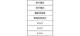
ゲートウエイ10は、二次電池状態検出装置21からLIN20に送出された二次電池状態情報をLIN I/F11によって受信する。制御部13は、LIN I/F11によって受信された二次電池状態情報を、その種類によって分類した後、記憶部14に記憶させる。図4は、記憶部14に記憶される二次電池状態情報の一例を示している。図4の例では、二次電池状態情報としては、端子電圧、端子電流、電解液温度、等価回路成分、SOC、SOH、および、SOFが示されている。なお、これら以外の情報を記憶するようにしてもよい。
The
制御部13は、記憶部14に記憶されている図4に示す情報を、CAN I/F15を介して、エンジンECU31、ステアリング系ECU32、ボディ系ECU33、エアコンECU34、セキュリティECU35、および、運転支援系ECU36に対して定期的に送信する。より詳細には、制御部13は、記憶部14に記憶されている図4に示す情報を定期的に取得し、CAN I/F15に供給する。CAN I/F15は、CSMA/CAに基づいて、情報を各ECUに送信する。すなわち、CAN I/F15は、CAN20に流れている情報を受信することで、CAN20に接続されているECUが現在通信を行っているか否かを判定し、通信を行っていない場合には情報を送信し、通信を行っている場合にはランダムな待ち時間だけ待機した後に、再度受信を行い、通信を行っていない場合には情報を送信する。なお、定期的に送信するのではなく、例えば、二次電池状態情報の変化の大小に応じて、頻度を変えるようにしてもよい。
The control unit 13 converts the information shown in FIG. 4 stored in the storage unit 14 into the engine ECU 31, the
各ECUは、CAN I/F15によって送信された二次電池状態情報を受信し、制御対象に応じた処理を実行する。例えば、エンジンECU31では、二次電池23のSOCを取得し、SOCが所定の閾値よりも小さい場合には、例えば、オルタネータ24の発電電圧を高く設定することで充電を促進させる。また、SOCが所定の閾値(前述した閾値よりも大きい値の閾値)よりも大きい場合にはオルタネータ24の電圧を低く設定することで、エンジンにかかる負荷を軽減させ、燃費を向上させる。
Each ECU receives the secondary battery state information transmitted by the CAN I /
また、ステアリング系ECU32では、等価回路の抵抗成分と、電動ステアリング装置が動作したときに流れる電流とから、電動ステアリング装置が動作時の電圧降下を求める。そして、現在の端子電圧から電圧降下を減算して得た電圧値が、電動ステアリング装置の最低作動電圧よりも低い場合には、電動ステアリング装置に供給する電圧を昇圧することでスムーズに動作させることができる。あるいは、電動ステアリング装置に流れる電流を制限することで、過大な電流によって二次電池23の残量が急激に少なくなることを防ぐことができる。なお、電動制御ブレーキの場合も、同様の動作を行うことができる。
Further, the
また、ボディ系ECU33では、例えば、CAN I/F15によって送信された二次電池状態情報に含まれるSOCを参照し、SOCが所定の閾値よりも小さい場合には、ワイパーやパワーウィンドウの作動範囲の両端において、モータに供給する電流を制限することで、SOCが減少することを抑制することができる。より詳細には、ワイパーの場合には、作動範囲の両端において、ワイパーが進行方向を変えるが、その際に電流を多く消費するので、作動範囲の両端において電流を制限することで、SOCのさらなる減少を抑制することができる。また、パワーウィンドウの場合も、動作開始時および動作終了時に電力を多く消費するので、SOCが所定の閾値よりも小さい場合には、動作開始時および動作終了時に電流の制限を行うことで、SOCのさらなる減少を抑制することができる。
The
また、エアコンECU34の場合には、二次電池23のSOCが所定の閾値よりも小さい場合には、電動コンプレッサまたは送風機に供給する電力を制限することで、SOCのさらなる減少を抑制することができる。同様に、図示しないライトECUの場合には、二次電池23のSOCが所定の閾値よりも小さい場合には、ライト(例えば、ヘッドライトまたはフォグライト)に供給する電力を制限することで、SOCのさらなる減少を抑制することができる。なお、SOCではなく、端子電圧または端子電流から負荷における消費電力の多寡を判定し、消費電力が多い場合には、エアコンまたはライトに供給する電力を制限するようにしてもよい。
Further, in the case of the
また、セキュリティECU35または運転支援系ECU36の場合には、SOCまたは端子電圧に関する情報を取得し、SOCが所定の閾値以下になるか、または、端子電圧が所定の閾値以下になった場合には、動作が不能になると判定して、運転者に通知する制御を行うことができる。これにより、セキュリティや運転支援系の負荷が動作できなくなる可能性があることを運転者に事前に通知することができる。また、SOHを取得し、SOHが所定の閾値以下になった場合(二次電池23が所定以上に劣化した場合)には、運転者に通知して二次電池23の交換を促すようにしてもよい。
Further, in the case of the
つぎに、図5〜図8を参照して、本実施形態において実行される処理について説明する。図5は、ゲートウエイ10において、二次電池状態情報を取得する際に実行される処理の流れの一例を説明するフローチャートである。図5に示すフローチャートの処理が開始されると、以下のステップが実行される。
Next, processing executed in the present embodiment will be described with reference to FIGS. FIG. 5 is a flowchart for explaining an example of the flow of processing executed when the secondary battery state information is acquired in the
ステップS10では、制御部13は、所定の時間(例えば、1分)が経過したか否かを判定し、所定の時間が経過したと判定した場合(ステップS10:Y)にはステップS11に進み、それ以外の場合(ステップS10:N)には同様の処理を繰り返す。 In step S10, the control unit 13 determines whether or not a predetermined time (for example, 1 minute) has elapsed. If it is determined that the predetermined time has elapsed (step S10: Y), the control unit 13 proceeds to step S11. In other cases (step S10: N), the same processing is repeated.
ステップS11では、制御部13は、二次電池23の状態を示す二次電池状態情報を送信するように要求する送信要求を、二次電池状態検出装置21に対して送出する。より詳細には、制御部13は、LIN I/F11を制御して、LIN20にトークンを送出させる。トークンを受信した二次電池状態検出装置21は、トークンの後に二次電池状態情報をLIN20に送出する。
In step S <b> 11, the control unit 13 sends a transmission request for requesting to transmit secondary battery state information indicating the state of the
ステップS12では、制御部13は、LIN I/F11によって二次電池状態情報を受信したか否かを判定し、受信したと判定した場合(ステップS12:Y)にはステップS13に進み、それ以外の場合(ステップS12:N)には同様の処理を繰り返す。例えば、二次電池状態検出装置21がトークンを取得して二次電池状態情報をLIN20に送出し、これを受信した場合にはYと判定してステップS13に進む。
In step S12, the control unit 13 determines whether or not secondary battery state information has been received by the LIN I / F 11, and if it is determined that the secondary battery state information has been received (step S12: Y), the process proceeds to step S13. In this case (step S12: N), the same processing is repeated. For example, the secondary battery state detection device 21 acquires the token and sends the secondary battery state information to the
ステップS13では、制御部13は、ステップS12で受信した二次電池状態情報を、その種類に応じて分類する。例えば、二次電池状態検出装置21が送出する二次電池状態情報が、例えば、図4に示す順番にデータパケットに収められている場合には、格納順に基づいて情報を分類する。 In step S13, the control unit 13 classifies the secondary battery state information received in step S12 according to the type. For example, when the secondary battery state information sent out by the secondary battery state detection device 21 is stored in the data packet in the order shown in FIG. 4, for example, the information is classified based on the storage order.
ステップS14では、制御部13は、ステップS13において分類した二次電池状態情報を、記憶部14の所定の領域に記憶させる。例えば、制御部13は、ステップS13において分類した二次電池状態情報を、記憶部14の所定の記憶領域に対して、例えば、図4に示すような態様で記憶させる。 In step S14, the control unit 13 stores the secondary battery state information classified in step S13 in a predetermined area of the storage unit 14. For example, the control unit 13 stores the secondary battery state information classified in step S13 in a predetermined storage area of the storage unit 14 in a manner as shown in FIG.
ステップS15では、制御部13は、処理を繰り返すか否かを判定し、繰り返すと判定した場合(ステップS15:Y)にはステップS10に戻って前述の場合と同様の処理を繰り返し、それ以外の場合(ステップS15:N)には処理を終了する。 In step S15, the control unit 13 determines whether or not to repeat the process. If it is determined that the process is to be repeated (step S15: Y), the control unit 13 returns to step S10 and repeats the same process as described above. In the case (step S15: N), the process ends.
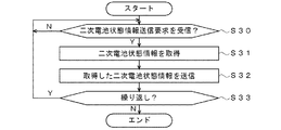
つぎに、図6を参照して、二次電池状態検出装置21において実行される処理について説明する。図6に示すフローチャートの処理が開始されると、以下のステップが実行される。 Next, processing executed in the secondary battery state detection device 21 will be described with reference to FIG. When the processing of the flowchart shown in FIG. 6 is started, the following steps are executed.
ステップS30では、二次電池状態検出装置21は、ゲートウエイ10から二次電池状態情報の送信要求を受信したか否かを判定し、送信要求を受信したと判定した場合(ステップS30:Y)にはステップS31に進み、それ以外の場合(ステップS30:N)には同様の処理を繰り返す。例えば、ゲートウエイ10から送信要求を示すトークンを受信した場合には、Yと判定してステップS31に進む。
In step S30, the secondary battery state detection device 21 determines whether or not a transmission request for secondary battery state information has been received from the
ステップS31では、二次電池状態検出装置21は、検出済みの二次電池状態情報を図示しない記憶部から取得する。例えば、二次電池状態検出装置21は、定期的に二次電池23の状態を検出し、図4に示すような情報を、図示しない記憶部に記憶しているので、これらの二次電池状態情報を記憶部から取得する。
In step S31, the secondary battery state detection device 21 acquires the detected secondary battery state information from a storage unit (not shown). For example, since the secondary battery state detection device 21 periodically detects the state of the
ステップS32では、二次電池状態検出装置21は、取得した二次電池状態情報を、LIN20を介して、ゲートウエイ10に対して送信する。より詳細には、二次電池状態検出装置21は、ゲートウエイ10から送信されるトークンを取得し、二次電池状態情報をLIN20に対して送出する。
In step S <b> 32, the secondary battery state detection device 21 transmits the acquired secondary battery state information to the
ステップS33では、二次電池状態検出装置21は、処理を繰り返すか否かを判定し、繰り返すと判定した場合(ステップS33:Y)にはステップS30に戻って前述の場合と同様の処理を繰り返し、それ以外の場合(ステップS33:N)には処理を終了する。 In step S33, the secondary battery state detection device 21 determines whether or not to repeat the process. If it is determined that the process is to be repeated (step S33: Y), the process returns to step S30 and the same process as described above is repeated. In other cases (step S33: N), the process ends.
つぎに、図7を参照して、ゲートウエイ10が二次電池状態情報を、CAN30を介して定期的に送信する処理について説明する。図7に示すフローチャートの処理が開始されると、以下のステップが実行される。
Next, a process in which the
ステップS50では、制御部13は、所定の時間(例えば、1分)が経過したか否かを判定し、所定の時間が経過したと判定した場合(ステップS50:Y)にはステップS51に進み、それ以外の場合(ステップS50:N)には同様の処理を繰り返す。 In step S50, the control unit 13 determines whether or not a predetermined time (for example, 1 minute) has elapsed. If it is determined that the predetermined time has elapsed (step S50: Y), the control unit 13 proceeds to step S51. In other cases (step S50: N), the same processing is repeated.
ステップS51では、制御部13は、記憶部14の所定の領域に格納されている二次電池状態情報を取得する。より詳細には、制御部13は、記憶部14に対して図4に示す態様で格納されている二次電池状態情報を取得する。 In step S <b> 51, the control unit 13 acquires secondary battery state information stored in a predetermined area of the storage unit 14. More specifically, the control unit 13 acquires the secondary battery state information stored in the storage unit 14 in the manner illustrated in FIG.
ステップS52では、制御部13は、ステップS51において取得した二次電池状態情報を、CAN I/F15を介してCAN30に送信する。より詳細には、CAN I/F15は、CSMA/CAに基づいて、CAN30に流れる情報を受信し、現在通信しているECUが存在しない場合には二次電池状態情報を送信し、通信しているECUが存在する場合には、ランダムな時間待った後、再度、通信しているECUの存在の有無を調べ、存在しない場合には二次電池状態情報を送信し、存在する場合にはランダムな時間待つ処理を繰り返す。
In step S52, the control unit 13 transmits the secondary battery state information acquired in step S51 to the
ステップS53では、制御部13は、処理を繰り返すか否かを判定し、繰り返すと判定した場合(ステップS53:Y)にはステップS50に戻って前述の場合と同様の処理を繰り返し、それ以外の場合(ステップS53:N)には処理を終了する。 In step S53, the control unit 13 determines whether or not to repeat the process. If it is determined that the process is to be repeated (step S53: Y), the control unit 13 returns to step S50 and repeats the same process as described above. In the case (step S53: N), the process ends.
つぎに、図8を参照して、各ECUで実行される処理の一例について説明する。図8に示すフローチャートの処理が開始されると、以下のステップが実行される。なお、各ECUで実行される処理は同様であるので、以下では、ステアリング系ECU32を例に挙げて説明する。 Next, an example of processing executed by each ECU will be described with reference to FIG. When the processing of the flowchart shown in FIG. 8 is started, the following steps are executed. In addition, since the process performed by each ECU is the same, below, it demonstrates taking the steering system ECU32 as an example.
ステップS70では、ステアリング系ECU32は、CAN20を介してゲートウエイ10から二次電池状態情報を受信したか否かを判定し、受信したと判定した場合(ステップS70:Y)にはステップS71に進み、それ以外の場合(ステップS70:N)には同様の処理を繰り返す。例えば、ステアリング系ECU32がゲートウエイ10から二次電池状態情報を受信した場合には、Yと判定してステップS71に進む。
In step S70, the
ステップS71では、ステアリング系ECU32は、二次電池状態情報から必要な情報を取得する。例えば、ステアリング系ECU32は、端子電圧と内部抵抗に関する情報を取得する。
In step S71, the
ステップS72では、ステアリング系ECU32は、ステップS71で取得した二次電池状態情報に基づいた処理を実行する。例えば、ステアリング系ECU32は、二次電池23の抵抗成分と、電動ステアリング装置が動作したときに流れる電流とから、電動ステアリング装置が動作時の電圧降下の値を求める。そして、現在の端子電圧から電圧降下の値を減算して得た電圧値が、電動ステアリング装置の最低作動電圧よりも低い場合には、電動ステアリング装置に供給する電圧を昇圧することでスムーズに動作させることができる。あるいは、電動ステアリング装置に流れる電流を制限することで、過大な電流によって二次電池23の残量が急激に少なくなることを防止することができる。もちろん、これら以外の処理を実行するようにしてもよい。
In step S72, the
ステップS73では、ステアリング系ECU32は、処理を繰り返すか否かを判定し、繰り返すと判定した場合(ステップS73:Y)にはステップS70に戻って前述の場合と同様の処理を繰り返し、それ以外の場合(ステップS73:N)には処理を終了する。
In step S73, the
以上に説明したように、本発明の実施形態によれば、それぞれのECUが二次電池23の状態を独自に判断することが可能となる。
As described above, according to the embodiment of the present invention, each ECU can independently determine the state of the
(C)変形実施形態の説明
以上の実施形態は一例であって、本発明が上述したような場合のみに限定されるものでないことはいうまでもない。例えば、以上の実施形態では、図3に示す等価回路を用いるようにしたが、これ以外の等価回路を用いるようにしてもよい。例えば、図3では、正極と負極に対応して、Rct1とC1の並列素子とRct2とC2の並列素子を有するようにしたが、これらのいずれか一方だけの等価回路としてもよい。あるいは、並列素子が3つ以上接続された等価回路を用いるようにしてもよい。また、内部抵抗Rだけの等価回路を用いるようにしてもよい。
(C) Description of Modified Embodiment It goes without saying that the above embodiment is merely an example, and the present invention is not limited to the case described above. For example, in the above embodiment, the equivalent circuit shown in FIG. 3 is used. However, other equivalent circuits may be used. For example, in FIG. 3, the parallel elements of Rct1 and C1 and the parallel elements of Rct2 and C2 are provided corresponding to the positive electrode and the negative electrode, but an equivalent circuit of only one of them may be used. Alternatively, an equivalent circuit in which three or more parallel elements are connected may be used. Further, an equivalent circuit including only the internal resistance R may be used.
また、以上の実施形態では、ゲートウエイ10は、1回の計測分の二次電池状態情報を記憶部14に記憶するようにしたが、複数回分の二次電池状態情報を格納し、各ECUに供給するようにしてもよい。そのような構成によれば、過去の複数回分の情報を参照することができるので、例えば、1日または数週間前の情報と比較することで、二次電池23の状態変化を検出することができる。例えば、SOHの経時的な変化を参照することで、二次電池23の交換時期を的確に判断することができる。また、二次電池状態情報の経時的な変化から、二次電池状態検出装置21の故障の有無を判定することもできる。例えば、二次電池状態情報が変化しなくなったり、あるいは急激に変化したりする場合には二次電池状態検出装置21の故障と判定するようにしてもよい。
Further, in the above embodiment, the
また、ゲートウエイ10が、二次電池23の検出結果に基づいて、使用状態を示す履歴情報を作成し、履歴情報に基づいて、二次電池23の状態を判定するようにしてもよい。より詳細には、ゲートウエイ10の制御部13が、取得したSOCおよび端子電流に基づいて過充電または過放電を検出し、過放電または過充電の頻度から、二次電池23の劣化状態を推定するようにしてもよい。また、二次電池23の電解液温度を検出し、電解液温度が所定の温度を下回った時間または上回った時間を履歴情報として記憶し、これらの情報に基づいて、二次電池23の劣化状態を推定するようにしてもよい。なお、このような処理は、ゲートウエイ10ではなく、ECUが実行するようにしてもよい。
Further, the
また、図2に示す実施形態において、温度センサ17および液面センサ18によって検出された情報を、記憶部14に合わせて格納し、これらの情報も参照して、二次電池23の状態を判定するようにしてもよい。例えば、温度センサ17によって検出される二次電池23の外部の温度は、電解液の温度に先行して変化することから、温度センサ17によって検出される外部温度を制御部13が取得し、所定の温度を超えた場合または下回った場合には、エンジンECU31に通知し、警告を発するようにしてもよい。また、電解液の量によって、二次電池23の状態情報が変化することから、電解液の量を参照して、二次電池状態情報を補正するようにしてもよい。
In the embodiment shown in FIG. 2, information detected by the
また、以上の実施形態では、エンジン車を例に挙げて説明したが、例えば、ハイブリッド車または電気自動車に本発明を適用するようにしてもよい。これらの車両では、12Vの二次電池以外にも、モータを駆動するための高圧系の二次電池を有しているので、この高圧系の二次電池の状態を検出する二次電池状態検出装置を、ゲートウエイ10に接続し、前述の場合と同様の処理を実行するようにしてもよい。また、12Vの予備電源を有する車両の場合には、予備電源に対して二次電池状態検出装置を設け、ゲートウエイ10に接続するようにしてもよい。
In the above embodiment, the engine vehicle has been described as an example, but the present invention may be applied to, for example, a hybrid vehicle or an electric vehicle. Since these vehicles have a high-voltage secondary battery for driving the motor in addition to the 12V secondary battery, the secondary battery state detection detects the state of the high-voltage secondary battery. A device may be connected to the
また、以上の実施形態では、ゲートウエイ10が接続するネットワークとしては、LIN20とCAN30を例に挙げて説明したが、これら以外のネットワークを相互に接続するようにしてもよい。例えば、FlexRayやMOST(Media Oriented Systems Transport)等を接続し、これらの間で情報を授受するようにしてもよい。
In the above embodiment, the
また、以上の実施形態では、ゲートウエイ10からCAN30に送出する二次電池状態情報の優先順位については言及していないが、他のECUから送出される情報との比較により、優先順位を付与するようにしてもよい。例えば、二次電池状態情報に対しては、ステアリング系ECU32やエンジンECU31よりも低い優先順位で、エアコンECU34よりも高い優先順位を付与するようにしてもよい。また、ゲートウエイ10が二次電池23の異常を検出した場合(例えば、正常な電圧を供給できない場合)には、最も高い優先順位を付与した情報(二次電池23の異常を示す情報)をCAN30に送出するようにしてもよい。
In the above embodiment, the priority order of the secondary battery state information sent from the
また、以上の実施形態では、二次電池状態検出装置21は、ゲートウエイ10に対して二次電池状態情報を一方的に送信する構成としたが、例えば、二次電池状態検出装置21からの要求に応じて、ゲートウエイ10が記憶部14に記憶している二次電池状態情報を送信するようにしてもよい。そのような構成によれば、ゲートウエイ10の記憶部14を二次電池状態検出装置21の外部記憶装置として利用することができるので、二次電池状態検出装置21により複雑な計算処理を実行させることができる。
Moreover, in the above embodiment, the secondary battery state detection device 21 is configured to transmit the secondary battery state information unilaterally to the
また、以上の実施形態では、ゲートウエイ10がCAN30に対して二次電池状態情報を定期的に送信するようにしたが、例えば、各ECUからの要求に基づいて、二次電池状態情報を送信するようにしてもよい。
In the above embodiment, the
また、以上の実施形態では、ゲートウエイ10がCAN30を介して各ECUと接続するようにしたが、例えば、自動運転制御を行う制御部とゲートウエイ10がCAN30を介して接続するようにしてもよい。そのような構成によれば、自動運転制御を行う制御部が、ゲートウエイ10から二次電池状態情報を取得することができるので、二次電池23の状態を参照して、最適な制御を実行することができる。より詳細には、二次電池23に異常が生じた場合には、最寄りの整備工場まで案内したり、より緊急度が高い場合には駐車スペースまで案内したりすることができる。
In the above embodiment, the
10 ゲートウエイ(接続装置)
11 LIN I/F(第1送受信手段)
12 A/D変換部(入力手段)
13 制御部(取得手段、供給手段、判定手段)
14 記憶部(記憶手段)
15 CAN I/F(第2送受信手段)
16 バス
17 温度センサ
18 液面センサ
20 LIN(第1ネットワーク)
21 二次電池状態検出装置
22 センサ部
23 二次電池
24 オルタネータ
25 スタータモータ
30 CAN(第2ネットワーク)
31 エンジンECU
32 ステアリング系ECU
33 ボディ系ECU
34 エアコンECU
35 セキュリティECU
36 運転支援系ECU
10 Gateway (connection device)
11 LIN I / F (first transmission / reception means)
12 A / D converter (input means)
13 Control unit (acquisition means, supply means, determination means)
14 Storage unit (storage means)
15 CAN I / F (second transmission / reception means)
16
DESCRIPTION OF SYMBOLS 21 Secondary battery
31 Engine ECU
32 Steering system ECU
33 Body ECU
34 Air conditioner ECU
35 Security ECU
36 Driving assistance ECU
Claims (7)
二次電池の状態を検出する二次電池状態検出装置との間で前記第1ネットワークを介して情報を送受信する第1送受信手段と、
車両の各部を制御する1または複数のECU(Electric Control Unit)との間で前記第2ネットワークを介して情報を送受信する第2送受信手段と、
前記第1送受信手段を介して前記二次電池状態検出装置から前記二次電池の状態を示す二次電池状態情報を取得する取得手段と、
前記取得手段によって取得された前記二次電池状態情報を記憶する記憶手段と、
前記記憶手段に記憶された前記二次電池状態情報を、前記第2送受信手段を介して前記1または複数のECUに供給する供給手段と、
を有することを特徴とする接続装置。 In a connection device for connecting a first network and a second network having a communication protocol different from that of the first network and exchanging information between them,
First transmission / reception means for transmitting / receiving information to / from a secondary battery state detection device for detecting a state of the secondary battery via the first network;
Second transmission / reception means for transmitting / receiving information to / from one or more ECUs (Electric Control Units) for controlling each part of the vehicle via the second network;
Obtaining means for obtaining secondary battery state information indicating the state of the secondary battery from the secondary battery state detection device via the first transmission / reception means;
Storage means for storing the secondary battery state information acquired by the acquisition means;
Supply means for supplying the secondary battery state information stored in the storage means to the one or more ECUs via the second transmission / reception means;
A connection device comprising:
前記記憶手段は、前記入力手段から入力された情報についても、前記二次電池状態情報として記憶する、
ことを特徴とする請求項1に記載の接続装置。 An input unit that inputs information from a sensor that detects a state different from the state detected by the secondary battery state detection device;
The storage means also stores information inputted from the input means as the secondary battery state information.
The connection device according to claim 1.
前記判定手段によって前記二次電池状態検出装置が故障していると判定された場合には、前記第2送受信手段を介して前記ECUに対して故障の発生を通知する、
ことを特徴とする請求項1乃至3のいずれか1項に記載の接続装置。 Based on the secondary battery state information, having a determination means for determining the presence or absence of a failure of the secondary battery state detection device,
When the determination means determines that the secondary battery state detection device is out of order, the ECU notifies the ECU of the occurrence of the failure via the second transmission / reception means.
The connection device according to any one of claims 1 to 3, wherein
前記供給手段は、前記記憶手段に記憶されている前記過去に取得された前記二次電池状態情報を前記ECUに対して供給する、
ことを特徴とする請求項1乃至4のいずれか1項に記載の接続装置。 The storage means further stores the secondary battery state information acquired in the past by the acquisition means,
The supply means supplies the ECU with the secondary battery state information acquired in the past stored in the storage means;
The connection device according to any one of claims 1 to 4, wherein the connection device is provided.
前記第2ネットワークはCAN(Controller Area Network)である、
ことを特徴とする請求項1乃至5のいずれか1項に記載の接続装置。 The first network is a LIN (Local Interconnect Network),
The second network is a CAN (Controller Area Network).
The connection device according to claim 1, wherein the connection device is a device.
Priority Applications (1)
| Application Number | Priority Date | Filing Date | Title |
|---|---|---|---|
| JP2016106108A JP6754222B2 (en) | 2016-05-27 | 2016-05-27 | Connection device and network system |
Applications Claiming Priority (1)
| Application Number | Priority Date | Filing Date | Title |
|---|---|---|---|
| JP2016106108A JP6754222B2 (en) | 2016-05-27 | 2016-05-27 | Connection device and network system |
Publications (2)
| Publication Number | Publication Date |
|---|---|
| JP2017210182A true JP2017210182A (en) | 2017-11-30 |
| JP6754222B2 JP6754222B2 (en) | 2020-09-09 |
Family
ID=60475130
Family Applications (1)
| Application Number | Title | Priority Date | Filing Date |
|---|---|---|---|
| JP2016106108A Active JP6754222B2 (en) | 2016-05-27 | 2016-05-27 | Connection device and network system |
Country Status (1)
| Country | Link |
|---|---|
| JP (1) | JP6754222B2 (en) |
Cited By (4)
| Publication number | Priority date | Publication date | Assignee | Title |
|---|---|---|---|---|
| WO2021010324A1 (en) * | 2019-07-18 | 2021-01-21 | マツダ株式会社 | Network hub device |
| WO2021010322A1 (en) * | 2019-07-18 | 2021-01-21 | マツダ株式会社 | Network hub device |
| US11604225B2 (en) | 2019-12-23 | 2023-03-14 | Gs Yuasa International Ltd. | Method for estimating state of charge, liquid reduction amount of electrolyte solution of valve regulated lead-acid battery, and device for monitoring valve regulated lead-acid |
| WO2023112985A1 (en) * | 2021-12-16 | 2023-06-22 | 古河電気工業株式会社 | Battery status detection device, information processing system, and data collection method |
Citations (5)
| Publication number | Priority date | Publication date | Assignee | Title |
|---|---|---|---|---|
| JP2010076595A (en) * | 2008-09-26 | 2010-04-08 | Honda Motor Co Ltd | Load control device for vehicle |
| US20120038473A1 (en) * | 2010-08-10 | 2012-02-16 | General Motors Llc | Wireless monitoring of battery for lifecycle management |
| JP2012050240A (en) * | 2010-08-26 | 2012-03-08 | Toshiba Corp | Battery pack module, vehicle and processor |
| WO2012160668A1 (en) * | 2011-05-25 | 2012-11-29 | トヨタ自動車株式会社 | Vehicle communication apparatus |
| JP2014058267A (en) * | 2012-09-19 | 2014-04-03 | Auto Network Gijutsu Kenkyusho:Kk | Vehicular power generation control system |
-
2016
- 2016-05-27 JP JP2016106108A patent/JP6754222B2/en active Active
Patent Citations (5)
| Publication number | Priority date | Publication date | Assignee | Title |
|---|---|---|---|---|
| JP2010076595A (en) * | 2008-09-26 | 2010-04-08 | Honda Motor Co Ltd | Load control device for vehicle |
| US20120038473A1 (en) * | 2010-08-10 | 2012-02-16 | General Motors Llc | Wireless monitoring of battery for lifecycle management |
| JP2012050240A (en) * | 2010-08-26 | 2012-03-08 | Toshiba Corp | Battery pack module, vehicle and processor |
| WO2012160668A1 (en) * | 2011-05-25 | 2012-11-29 | トヨタ自動車株式会社 | Vehicle communication apparatus |
| JP2014058267A (en) * | 2012-09-19 | 2014-04-03 | Auto Network Gijutsu Kenkyusho:Kk | Vehicular power generation control system |
Cited By (10)
| Publication number | Priority date | Publication date | Assignee | Title |
|---|---|---|---|---|
| WO2021010324A1 (en) * | 2019-07-18 | 2021-01-21 | マツダ株式会社 | Network hub device |
| WO2021010322A1 (en) * | 2019-07-18 | 2021-01-21 | マツダ株式会社 | Network hub device |
| JP2021019235A (en) * | 2019-07-18 | 2021-02-15 | マツダ株式会社 | Network hub device |
| JP2021019233A (en) * | 2019-07-18 | 2021-02-15 | マツダ株式会社 | Network hub device |
| CN114097258A (en) * | 2019-07-18 | 2022-02-25 | 马自达汽车株式会社 | Network line concentrator |
| US11804978B2 (en) | 2019-07-18 | 2023-10-31 | Mazda Motor Corporation | Network hub device |
| JP7408939B2 (en) | 2019-07-18 | 2024-01-09 | マツダ株式会社 | network hub device |
| JP7408940B2 (en) | 2019-07-18 | 2024-01-09 | マツダ株式会社 | network hub device |
| US11604225B2 (en) | 2019-12-23 | 2023-03-14 | Gs Yuasa International Ltd. | Method for estimating state of charge, liquid reduction amount of electrolyte solution of valve regulated lead-acid battery, and device for monitoring valve regulated lead-acid |
| WO2023112985A1 (en) * | 2021-12-16 | 2023-06-22 | 古河電気工業株式会社 | Battery status detection device, information processing system, and data collection method |
Also Published As
| Publication number | Publication date |
|---|---|
| JP6754222B2 (en) | 2020-09-09 |
Similar Documents
| Publication | Publication Date | Title |
|---|---|---|
| US10967753B2 (en) | Vehicle, charger, charging system including charger, and abnormality diagnosis method for charger | |
| JP6400205B2 (en) | Battery management system based on wireless network | |
| JP5853099B2 (en) | Battery control device | |
| JP6754222B2 (en) | Connection device and network system | |
| US10637107B2 (en) | Vehicle communication system, battery management device, circuit board, battery, and communication specification switching method | |
| US10476280B2 (en) | Energy storage management device deciding charge voltage based on difference in charge amount or voltage difference between energy storage devices | |
| US9551750B2 (en) | Monitoring system and vehicle | |
| JP6446325B2 (en) | Power supply device | |
| CN110386009B (en) | Vehicle and charging system | |
| WO2013094015A1 (en) | Battery monitoring and control integrated circuit and a battery system | |
| JP5838224B2 (en) | Battery control device | |
| JP2016082846A (en) | Electric vehicle | |
| JP7140082B2 (en) | Sensor abnormality determination device | |
| JP2015141117A (en) | Deterioration state estimation device for battery | |
| JP2015177234A (en) | battery module and CAN communication identifier setting method | |
| JP2015100179A (en) | Battery monitoring device | |
| US11462913B2 (en) | Power control system, power control device and controlled device | |
| JP2021128023A (en) | Battery diagnostic device and vehicle | |
| JP2020061823A (en) | Secondary battery control device | |
| JP2020156303A (en) | Battery control apparatus | |
| JP2014147139A (en) | Storage battery system | |
| HUE033451T2 (en) | Method for energy supply management | |
| JP2023004022A (en) | charging system | |
| JP2008232988A (en) | Power storage device | |
| JP2015208072A (en) | Battery management apparatus |
Legal Events
| Date | Code | Title | Description |
|---|---|---|---|
| A621 | Written request for application examination |
Free format text: JAPANESE INTERMEDIATE CODE: A621 Effective date: 20190322 |
|
| RD03 | Notification of appointment of power of attorney |
Free format text: JAPANESE INTERMEDIATE CODE: A7423 Effective date: 20200117 |
|
| A977 | Report on retrieval |
Free format text: JAPANESE INTERMEDIATE CODE: A971007 Effective date: 20200122 |
|
| A521 | Request for written amendment filed |
Free format text: JAPANESE INTERMEDIATE CODE: A523 Effective date: 20200303 |
|
| A131 | Notification of reasons for refusal |
Free format text: JAPANESE INTERMEDIATE CODE: A131 Effective date: 20200310 |
|
| A521 | Request for written amendment filed |
Free format text: JAPANESE INTERMEDIATE CODE: A523 Effective date: 20200501 |
|
| TRDD | Decision of grant or rejection written | ||
| A01 | Written decision to grant a patent or to grant a registration (utility model) |
Free format text: JAPANESE INTERMEDIATE CODE: A01 Effective date: 20200804 |
|
| A61 | First payment of annual fees (during grant procedure) |
Free format text: JAPANESE INTERMEDIATE CODE: A61 Effective date: 20200821 |
|
| R151 | Written notification of patent or utility model registration |
Ref document number: 6754222 Country of ref document: JP Free format text: JAPANESE INTERMEDIATE CODE: R151 |
|
| S531 | Written request for registration of change of domicile |
Free format text: JAPANESE INTERMEDIATE CODE: R313531 |
|
| R350 | Written notification of registration of transfer |
Free format text: JAPANESE INTERMEDIATE CODE: R350 |