WO2018092485A1 - 工作機械の管理システム - Google Patents
工作機械の管理システム Download PDFInfo
- Publication number
- WO2018092485A1 WO2018092485A1 PCT/JP2017/037471 JP2017037471W WO2018092485A1 WO 2018092485 A1 WO2018092485 A1 WO 2018092485A1 JP 2017037471 W JP2017037471 W JP 2017037471W WO 2018092485 A1 WO2018092485 A1 WO 2018092485A1
- Authority
- WO
- WIPO (PCT)
- Prior art keywords
- machine tool
- information
- usage
- user
- unit
- Prior art date
Links
Images
Classifications
-
- G—PHYSICS
- G06—COMPUTING; CALCULATING OR COUNTING
- G06Q—INFORMATION AND COMMUNICATION TECHNOLOGY [ICT] SPECIALLY ADAPTED FOR ADMINISTRATIVE, COMMERCIAL, FINANCIAL, MANAGERIAL OR SUPERVISORY PURPOSES; SYSTEMS OR METHODS SPECIALLY ADAPTED FOR ADMINISTRATIVE, COMMERCIAL, FINANCIAL, MANAGERIAL OR SUPERVISORY PURPOSES, NOT OTHERWISE PROVIDED FOR
- G06Q20/00—Payment architectures, schemes or protocols
- G06Q20/08—Payment architectures
- G06Q20/14—Payment architectures specially adapted for billing systems
- G06Q20/145—Payments according to the detected use or quantity
-
- G—PHYSICS
- G06—COMPUTING; CALCULATING OR COUNTING
- G06Q—INFORMATION AND COMMUNICATION TECHNOLOGY [ICT] SPECIALLY ADAPTED FOR ADMINISTRATIVE, COMMERCIAL, FINANCIAL, MANAGERIAL OR SUPERVISORY PURPOSES; SYSTEMS OR METHODS SPECIALLY ADAPTED FOR ADMINISTRATIVE, COMMERCIAL, FINANCIAL, MANAGERIAL OR SUPERVISORY PURPOSES, NOT OTHERWISE PROVIDED FOR
- G06Q30/00—Commerce
- G06Q30/02—Marketing; Price estimation or determination; Fundraising
- G06Q30/0283—Price estimation or determination
-
- G—PHYSICS
- G05—CONTROLLING; REGULATING
- G05B—CONTROL OR REGULATING SYSTEMS IN GENERAL; FUNCTIONAL ELEMENTS OF SUCH SYSTEMS; MONITORING OR TESTING ARRANGEMENTS FOR SUCH SYSTEMS OR ELEMENTS
- G05B19/00—Programme-control systems
- G05B19/02—Programme-control systems electric
- G05B19/18—Numerical control [NC], i.e. automatically operating machines, in particular machine tools, e.g. in a manufacturing environment, so as to execute positioning, movement or co-ordinated operations by means of programme data in numerical form
- G05B19/406—Numerical control [NC], i.e. automatically operating machines, in particular machine tools, e.g. in a manufacturing environment, so as to execute positioning, movement or co-ordinated operations by means of programme data in numerical form characterised by monitoring or safety
- G05B19/4063—Monitoring general control system
-
- G—PHYSICS
- G05—CONTROLLING; REGULATING
- G05B—CONTROL OR REGULATING SYSTEMS IN GENERAL; FUNCTIONAL ELEMENTS OF SUCH SYSTEMS; MONITORING OR TESTING ARRANGEMENTS FOR SUCH SYSTEMS OR ELEMENTS
- G05B19/00—Programme-control systems
- G05B19/02—Programme-control systems electric
- G05B19/418—Total factory control, i.e. centrally controlling a plurality of machines, e.g. direct or distributed numerical control [DNC], flexible manufacturing systems [FMS], integrated manufacturing systems [IMS], computer integrated manufacturing [CIM]
-
- G—PHYSICS
- G06—COMPUTING; CALCULATING OR COUNTING
- G06Q—INFORMATION AND COMMUNICATION TECHNOLOGY [ICT] SPECIALLY ADAPTED FOR ADMINISTRATIVE, COMMERCIAL, FINANCIAL, MANAGERIAL OR SUPERVISORY PURPOSES; SYSTEMS OR METHODS SPECIALLY ADAPTED FOR ADMINISTRATIVE, COMMERCIAL, FINANCIAL, MANAGERIAL OR SUPERVISORY PURPOSES, NOT OTHERWISE PROVIDED FOR
- G06Q10/00—Administration; Management
-
- G—PHYSICS
- G06—COMPUTING; CALCULATING OR COUNTING
- G06Q—INFORMATION AND COMMUNICATION TECHNOLOGY [ICT] SPECIALLY ADAPTED FOR ADMINISTRATIVE, COMMERCIAL, FINANCIAL, MANAGERIAL OR SUPERVISORY PURPOSES; SYSTEMS OR METHODS SPECIALLY ADAPTED FOR ADMINISTRATIVE, COMMERCIAL, FINANCIAL, MANAGERIAL OR SUPERVISORY PURPOSES, NOT OTHERWISE PROVIDED FOR
- G06Q30/00—Commerce
- G06Q30/06—Buying, selling or leasing transactions
- G06Q30/0645—Rental transactions; Leasing transactions
-
- G—PHYSICS
- G06—COMPUTING; CALCULATING OR COUNTING
- G06Q—INFORMATION AND COMMUNICATION TECHNOLOGY [ICT] SPECIALLY ADAPTED FOR ADMINISTRATIVE, COMMERCIAL, FINANCIAL, MANAGERIAL OR SUPERVISORY PURPOSES; SYSTEMS OR METHODS SPECIALLY ADAPTED FOR ADMINISTRATIVE, COMMERCIAL, FINANCIAL, MANAGERIAL OR SUPERVISORY PURPOSES, NOT OTHERWISE PROVIDED FOR
- G06Q50/00—Systems or methods specially adapted for specific business sectors, e.g. utilities or tourism
- G06Q50/04—Manufacturing
-
- G—PHYSICS
- G07—CHECKING-DEVICES
- G07F—COIN-FREED OR LIKE APPARATUS
- G07F17/00—Coin-freed apparatus for hiring articles; Coin-freed facilities or services
- G07F17/0042—Coin-freed apparatus for hiring articles; Coin-freed facilities or services for hiring of objects
-
- G—PHYSICS
- G05—CONTROLLING; REGULATING
- G05B—CONTROL OR REGULATING SYSTEMS IN GENERAL; FUNCTIONAL ELEMENTS OF SUCH SYSTEMS; MONITORING OR TESTING ARRANGEMENTS FOR SUCH SYSTEMS OR ELEMENTS
- G05B2219/00—Program-control systems
- G05B2219/30—Nc systems
- G05B2219/31—From computer integrated manufacturing till monitoring
- G05B2219/31408—Cost calculation of use of certain machine types
-
- Y—GENERAL TAGGING OF NEW TECHNOLOGICAL DEVELOPMENTS; GENERAL TAGGING OF CROSS-SECTIONAL TECHNOLOGIES SPANNING OVER SEVERAL SECTIONS OF THE IPC; TECHNICAL SUBJECTS COVERED BY FORMER USPC CROSS-REFERENCE ART COLLECTIONS [XRACs] AND DIGESTS
- Y02—TECHNOLOGIES OR APPLICATIONS FOR MITIGATION OR ADAPTATION AGAINST CLIMATE CHANGE
- Y02P—CLIMATE CHANGE MITIGATION TECHNOLOGIES IN THE PRODUCTION OR PROCESSING OF GOODS
- Y02P90/00—Enabling technologies with a potential contribution to greenhouse gas [GHG] emissions mitigation
- Y02P90/02—Total factory control, e.g. smart factories, flexible manufacturing systems [FMS] or integrated manufacturing systems [IMS]
-
- Y—GENERAL TAGGING OF NEW TECHNOLOGICAL DEVELOPMENTS; GENERAL TAGGING OF CROSS-SECTIONAL TECHNOLOGIES SPANNING OVER SEVERAL SECTIONS OF THE IPC; TECHNICAL SUBJECTS COVERED BY FORMER USPC CROSS-REFERENCE ART COLLECTIONS [XRACs] AND DIGESTS
- Y02—TECHNOLOGIES OR APPLICATIONS FOR MITIGATION OR ADAPTATION AGAINST CLIMATE CHANGE
- Y02P—CLIMATE CHANGE MITIGATION TECHNOLOGIES IN THE PRODUCTION OR PROCESSING OF GOODS
- Y02P90/00—Enabling technologies with a potential contribution to greenhouse gas [GHG] emissions mitigation
- Y02P90/30—Computing systems specially adapted for manufacturing
Definitions
- the present invention relates to a machine tool management system that manages, via the Internet, one or more machine tools disposed in a place where a specific or unspecified user can use them.
- the user management device is connected to each numerical control unit (control device) of one or more machine tools including a drive mechanism unit and a numerical control unit that controls the operation of the drive mechanism unit. Yes.
- the user management device collects data on the operation status of each drive mechanism unit from each numerical control unit by collecting user-side operation data storage means for storing data on the operation status of the drive mechanism unit of each machine tool, and In addition to accumulating in the user-side operation data storage means, it is confirmed whether or not a preset transmission condition is satisfied, and only when the transmission condition is satisfied, is accumulated in the user-side operation data storage means.
- Data transmission means for transmitting operation status data of each drive mechanism section to the manufacturer management apparatus in the data format of an e-mail.
- the manufacturer management device includes manufacturer-side operation data storage means for storing operation status data of each drive mechanism unit received from the user management device, and operation status data of each drive mechanism unit transmitted from the user management device.
- the data receiving means for updating the operating status data stored in the manufacturer operating data storage means with the received operating status data, and the consumption level for storing the data related to the consumption level of each drive mechanism section
- the wear level of each drive mechanism section is evaluated at any time and stored in the wear level data storage means.
- Consumption level evaluation means for updating the consumption level data with the evaluated consumption level data, and consumption level data stored in the consumption level data storage means. From time to time monitors whether exceeded because set reference value, if it exceeds the reference value, and an alarm output means for outputting an alarm to that effect.
- the data transmission means of each user management device collects data (operation status data) related to the operation status of each drive mechanism unit from the numerical control unit of each machine tool, and these are collected by the user. Accumulated in the side operation data storage means. Whether or not a predetermined transmission condition is satisfied is confirmed at any time, and only when this transmission condition is satisfied, the operation status data of each drive mechanism section stored in the user-side operation data storage means is electronic. It is sent to the manufacturer management device in the mail data format.
- the transmitted operating status data is received by the data receiving means, and the operating status data of each drive mechanism section stored in the manufacturer-side operating data storage means is updated with the received operating status data. Further, the wear level evaluation unit evaluates the wear level of each drive mechanism unit as needed based on the operation status data of each drive mechanism unit stored in the manufacturer side operation data storage unit, and stores it in the wear level data storage unit. The consumption level data is updated with the evaluated consumption level data. The consumption level data stored in the consumption level data storage means is monitored at any time by the alarm output means to determine whether or not the predetermined reference value has been exceeded. An alarm to the effect is output.
- the degree of wear of the drive mechanism portion of each machine tool is evaluated and monitored as needed, and when the degree of wear exceeds a predetermined reference value, that is, the wear of the drive mechanism portion.
- An alarm is output when a part is nearing the end of its life. Based on the output alarm, manufacturers can easily identify consumable parts that are nearing the end of their life. It is possible to predict when and how much parts are needed. As a result, there is no need to have extra inventory for consumable parts, which can be greatly reduced.
- Such a high-performance machine tool is naturally more expensive than a general-purpose machine tool, and requires a considerable amount of capital investment when including peripheral devices. Therefore, as a user, if the work rate of the machine tool that is being considered for introduction is to ensure a work rate that is profitable, or if such work amount is predicted, consider it Although it is possible to proceed with the introduction of existing machine tools, it is necessary to refrain from capital investment if this is not the case.
- the present invention has been made in view of the above circumstances, is not limited by the area where the machine tool is installed, and can efficiently charge a usage fee according to the use state of the machine tool.
- the purpose is to provide a machine tool management system.
- One or more machine tools provided with a use monitoring device having a communication function for connecting to the Internet and disposed in a place where a specific or unspecified user can use;
- a machine tool management system comprising a management device connected to the Internet and communicating with each usage monitoring device, The usage monitoring device is configured to transmit information related to a usage state of the machine tool to the management device,
- the management device is configured to calculate a fee according to a usage state of the machine tool received from the usage monitoring device as a usage fee, and then perform processing for charging the calculated user to the corresponding user.
- a machine tool management system comprising a management device connected to the Internet and communicating with each usage monitoring device, The usage monitoring device is configured to transmit information related to a usage state of the machine tool to the management device, The management device is configured to calculate a fee according to a usage state of the machine tool received from the usage monitoring device as a usage fee, and then perform processing for charging the calculated user to the corresponding user.
- At least one of the machine tools is disposed in a place where a specific or unspecified user can use it.
- a specific user uses the machine tool
- the machine tool is disposed in the user's factory.
- an unspecified user for example, it is arranged in a building set by the manufacturer of the machine tool.
- These machine tools have a usage monitoring device attached to the machine tool connected to the Internet, and can communicate with a management device also connected to the Internet.
- This management device is under the control of the manufacturer of the machine tool, but the installation location is not particularly limited.
- information related to the use state of the machine tool is obtained from the use monitoring device attached to the machine tool. Sent to.
- the information relating to the usage state forms a calculation basis for charging the user with an appropriate cost for using the machine tool, and includes, for example, the usage time of the machine tool.
- the management device calculates a cost according to the usage state of the machine tool received from the usage monitoring device as a usage fee, and executes a process of charging the calculated usage fee to the corresponding user.
- the user does not need to purchase a machine tool, and can perform necessary machining if paying a usage fee according to the use. Therefore, even if the user does not have enough work to fully operate the machine tool, the user can perform processing according to the work without newly installing the machine tool, and the required demand can be met. I can respond.
- the user can update the existing machine tool with a state-of-the-art machine tool without capital investment. Even if there is no risk or there is a risk that the demand will fluctuate suddenly, the renewal of the equipment is promoted.
- machine tool manufacturers can realize stable planned production that is easy to secure profits by creating new demand that does not depend on capital investment.
- a management system is a system through the Internet, there is no restriction on the area where the machine tool is installed. For example, the machine tool can be installed overseas. Even in the case of the arrangement, so-called charging processing can be performed efficiently.
- the management device is configured to settle a charge to the corresponding user by a process linked to the corresponding usage monitoring device.
- Such linked payment means an electronic payment that the user charges the cost charged to the user from the management device through the Internet by the user using the usage monitoring device. , Including payment by credit card and automatic debit from the bank account of the user.
- the usage monitoring device is configured to execute a process of performing user registration with respect to the management device,
- the management device is configured to execute a process of transmitting registered user identification information to a corresponding usage monitoring device.
- the user who uses the management system of the machine tool can be clarified, and the user who has been registered once and given identification information can be charged with high reliability. Can be executed.
- information such as a user's usage history can be accumulated, and by utilizing the accumulated information effectively, it is possible to predict the trend of user orders and future capital investment.
- the machine tool is provided with related facilities and functions used for processing using the machine tool.
- the usage monitoring device may be configured to transmit information relating to the usage state of the machine tool including information relating to the usage state of the related equipment and related functions to the management device.
- the related equipment and related functions include, for example, an automatic programming device, an interactive programming device, a special cycle function, a tool measuring system, and a workpiece measuring system.
- the user may desire to use these related facilities and related functions depending on the processing. According to this configuration, the user can use these related facilities and related functions as necessary, and the machine tool manufacturer can charge the cost according to their use.
- the machine tool includes a turning mechanism as a basic mechanism, and as an additional mechanism, a tailstock mechanism, a steady rest mechanism, a milling mechanism, a second and subsequent tool rests, and a second and subsequent main spindle mechanisms. And one or more mechanisms selected from a coolant mechanism,
- the usage monitoring device may be configured to transmit information relating to the usage state of the machine tool, including information relating to the usage state of the additional mechanism, to the management device.
- the user may wish to use this additional mechanism in addition to the turning mechanism as the basic mechanism.
- the user can use this additional mechanism as necessary, and the machine tool manufacturer can charge a cost according to the use of these additional mechanisms.
- the machine tool includes a milling mechanism as a basic mechanism, and the additional mechanism is selected from a turning axis other than the tool spindle, a mechanism related to the U axis of the tool spindle, a work clamp mechanism, and a coolant mechanism.
- the usage monitoring device may be configured to transmit information relating to the usage state of the machine tool, including information relating to the usage state of the additional mechanism, to the management device.
- the user may desire to use the additional mechanism in addition to the milling mechanism as the basic mechanism. According to this configuration, the user can use this additional mechanism as necessary, and the machine tool manufacturer can charge a cost according to the use of these additional mechanisms.
- the machine tool includes a peripheral mechanism provided in the periphery in addition to the main body mechanism for performing processing
- the usage monitoring device may be configured to transmit information relating to the usage state of the machine tool including information relating to the usage state of the peripheral mechanism to the management device.
- the peripheral mechanism includes, for example, a robot and a work loading / unloading device.
- the user may desire to use a peripheral mechanism in addition to the main body mechanism depending on the processing. According to this configuration, the user can use the peripheral mechanism as necessary, and the machine tool manufacturer can charge a cost according to the use thereof.
- the main body mechanism mentioned here is a concept including the basic mechanism and the additional mechanism.
- an accessory used for processing using the machine tool is provided around the machine tool
- the usage monitoring device may be configured to transmit information relating to the usage state of the machine tool, including information relating to the usage state of the accessory, to the management device.
- the accessory includes, for example, a chuck, a raw nail, a tool (including a tool holder), a throw-away tip, a detachable measuring device, and the like.
- the user may desire to use an accessory that can be used with the machine tool in addition to the machine tool. According to this configuration, the user can use the accessory as necessary, and the machine tool manufacturer can charge a cost according to the use of the accessory.
- the machine tool is provided with various sensors that detect the state of the machine tool.
- the usage monitoring device may be configured to transmit information obtained from the various sensors to the management device as information relating to a usage state of the machine tool.
- the sensor includes, for example, a power meter, a motor load ammeter, an accelerometer, a thermometer, and the like.
- Information obtained from the sensor includes, for example, power amount data, spindle motor load data, and feed motor load data.
- the vibration data of each part of the machine tool and the temperature data of each part of the machine tool are included. By collecting such information, it is possible to obtain data relating to the load state of each machine tool and the performance of the machine tool with respect to the load, which can be used for the development and improvement of the next machine tool.
- the management device analyzes the information obtained from the various sensors received from the usage monitoring device, and predicts whether or not there is an abnormality in the corresponding machine tool. Even if it is configured to transmit a signal regarding the abnormality to the use monitoring device when it is recognized that there is an abnormality or when it is predicted that an abnormal state is expected good. In this way, the user can use the machine tool with peace of mind. Predicting that an abnormal condition will occur means that an abnormal condition will occur in the near future. For the near future, for example, depending on the number of days that the machine tool manufacturer can handle before becoming abnormal. Means the future.
- the usage monitoring device is configured to transmit data related to an operating state acquired from a corresponding machine tool to the management device
- the management apparatus may be configured to accumulate the received data relating to the operating state, analyze the accumulated data, and retain at least the production technology information.
- the data (operation information) related to the operating state includes, for example, data such as cutting conditions (including cutting speed, feed speed, work material, tool material, etc.), tool life data, spindle rotation speed, and the like. included.
- cutting conditions including cutting speed, feed speed, work material, tool material, etc.
- tool life data including cutting speed, feed speed, work material, tool material, etc.
- spindle rotation speed included.
- the usage monitoring device executes processing for requesting the management device to use the production technology information held in the management device
- the said management apparatus may be comprised so that the said usage fee which concerns on a corresponding machine tool may be calculated according to the presence or absence of use of the said production technical information.
- the management device accumulates highly reliable production technology information having a wide range. Therefore, the user can perform more appropriate processing by using such production technology information.
- the machine tool maker provides the accumulated production technology information to the user and charges the usage fee according to the use, the profit can be increased.
- the machine tool is disposed in a place where an unspecified user can use it.
- the usage monitoring device is: Execute a process for requesting permission to use the machine tool to the management device; When the use permission is obtained from the management device, the processing device is configured to execute a process for enabling the machine tool, The management device When a signal requesting permission to use the corresponding machine tool is received from the use monitoring device, a process for recognizing the user is executed, and a process for determining whether or not the user can be used and returning the process to the use monitoring device is executed. It may be configured as follows.
- the machine tool is arranged in a place where an unspecified user can use it.
- the use monitoring device performs processing for requesting the management device to use the machine tool, and processing for making the machine tool usable when use permission is obtained from the management device. Execute.
- the management device determines the user and determines whether or not the use can be performed, and returns it to the use monitoring device. Process.
- the user can use the corresponding machine tool only when the user is recognized by the management device and its use is approved. Therefore, for users who have used improperly in the past or for users who have not made appropriate payments, their use can be eliminated, and in this way, proper operation of the system can be achieved. Can improve safety.
- the user does not need to purchase a machine tool, and can perform necessary processing by paying a usage fee according to use. Therefore, even if the user does not have enough work to fully operate the machine tool, the user can perform processing according to the work without newly installing the machine tool, and the required demand can be met. I can respond. In addition, by paying a usage fee according to the use of the machine tool in this way, the user can update the existing machine tool with a state-of-the-art machine tool without capital investment. Even if there is no risk or there is a risk that the demand will fluctuate suddenly, the renewal of the equipment is promoted.
- machine tool manufacturers can realize stable planned production that is easy to secure profits by creating new demand that does not depend on capital investment.
- a management system is a system through the Internet, there is no restriction on the area where the machine tool is installed. For example, the machine tool can be installed overseas. Even in the case of the arrangement, so-called charging processing can be performed efficiently.
- FIG. 1 is a block diagram showing a schematic configuration of a machine tool management system according to an embodiment of the present invention. It is a block diagram showing composition of a use monitoring device, a machine tool, etc. concerning this embodiment. It is the block diagram which showed the structure of the management apparatus which concerns on this embodiment. It is the flowchart which showed the usage procedure of the machine tool in the machine tool management system of this embodiment.
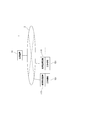
- FIG. 1 is a block diagram showing a schematic configuration of a machine tool management system (hereinafter simply referred to as “management system”) according to an embodiment of the present invention.
- the management system 1 of this example includes a management device 10 connected to the Internet 2 and a usage monitoring device 110, and a plurality of usage monitoring devices 110 connected to the Internet 2.
- Machine tool 101 As shown in FIG. 1, the management system 1 of this example includes a management device 10 connected to the Internet 2 and a usage monitoring device 110, and a plurality of usage monitoring devices 110 connected to the Internet 2.
- Machine tool 101 As shown in FIG. 1, the management system 1 of this example includes a management device 10 connected to the Internet 2 and a usage monitoring device 110, and a plurality of usage monitoring devices 110 connected to the Internet 2.
- Machine tool 101 As shown in FIG. 1, the management system 1 of this example includes a management device 10 connected to the Internet 2 and a usage monitoring device 110, and a plurality of usage monitoring devices 110 connected to the Internet 2.
- Machine tool 101 As shown in FIG. 1, the management system 1 of this example includes a management device 10 connected to the Internet 2 and a usage monitoring device 110, and a plurality of usage monitoring devices 110 connected to the Internet 2.
- Machine tool 101
- Each machine tool 101 can be used by a specific user, for example, a processing factory owned by a specific user, or a place that can be used by an unspecified user, such as a building set by a machine tool manufacturer. Arranged indoors. The building set by this machine tool manufacturer can be used by an unspecified number of users and has a concept of a machining center.
- the management apparatus 10 is under the management of the manufacturer of the machine tool, the installation location is not particularly limited. Details of each part will be described below.
- the machine tool 101 includes a basic mechanism 102 and an additional mechanism 103, and in addition to this, related equipment and related functions (hereinafter referred to as “related equipment”) 104, peripheral mechanisms 105, and various types.
- a sensor 107 is provided, and an accessory device 106 is disposed around the sensor 107.
- the basic mechanism 102 and the additional mechanism 103 are mechanisms for performing processing, and are considered as main body mechanisms.
- the machine tool 101 is not particularly limited, but examples of the most general machine include an NC lathe and a machining center.
- the basic mechanism 102 is a turning mechanism
- the additional mechanism 103 includes a tailstock mechanism, a steady rest mechanism, a milling mechanism, a second and subsequent tool rest, and a second and subsequent spindle mechanism.
- the coolant mechanism is selected from the coolant mechanism.
- the basic mechanism 102 is a milling mechanism
- the additional mechanism 103 is selected from a turning axis other than the tool spindle, a mechanism related to the U axis of the tool spindle, a work clamping mechanism, and a coolant mechanism.
- One or more mechanisms are illustrated.
- the related equipment 104 or the like is equipment or a function built in or attached to the machine tool 101, and examples thereof include an automatic programming device, an interactive programming device, a special cycle function, a tool measuring system, and a workpiece measuring system. .
- the peripheral mechanism 105 is a mechanism portion provided around the basic mechanism 102 and the additional mechanism 103 (main body mechanism) for performing processing.
- a robot or a work loading / unloading device including a loader
- the accessory tool 106 is a tool used for processing using the machine tool 101, and is disposed around the machine tool 101.
- the accessory 106 includes, for example, a chuck, a raw nail, a tool (including a tool holder), a throw-away tip, a detachable measuring device, and the like.
- the sensor 107 is attached to the machine tool 101.
- the sensor 107 includes, for example, a power meter, a motor load ammeter, an accelerometer, a thermometer, and the like. From these sensors 107, for example, electric energy data, spindle motor load data, feed motor load data, machine tools Information such as vibration data of each part and temperature data of each part of the machine tool is obtained.
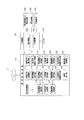
- each usage monitoring device 110 includes a usage permission request unit 111, a usage permission processing unit 112, a user registration application unit 113, an identification information display unit 114, a settlement processing unit 115, a usage information acquisition unit 116, Usage information storage unit 117, usage information transmission unit 118, sensor information acquisition unit 119, sensor information storage unit 120, sensor information transmission unit 121, operation information acquisition unit 122, operation information storage unit 123, operation information transmission unit 124, production technology
- the information request unit 125, the production technology information display unit 126, an abnormality signal reception unit 127, and an abnormality display unit 128 are included.
- the usage monitoring device 110 is composed of a general computer provided with an input device such as a keyboard and a display in addition to a CPU, ROM, and RAM.
- the sensor information transmission unit 121, the operation information acquisition unit 122, the operation information transmission unit 124, the production technology information request unit 125, the production technology information display unit 126, the abnormality signal reception unit 127, and the abnormality display unit 128 are appropriately configured by software. That function is realized.
- the usage information storage unit 117, the sensor information storage unit 120, and the operation information storage unit 123 are configured by an appropriate storage medium such as a RAM.
- the use permission request unit 111 receives the input identification
- the information related to the information and the contents of use is transmitted to the management device 10 and the management device 10 is requested to permit the use of the machine tool 101 and the like.
- a use permission signal is received from the management device 10
- a use permission signal is transmitted from the use permission processing unit 112 to the control device of the machine tool 101.
- the control device receives the use permission signal
- the board is changed from the unusable state (locked state) to the usable state (unlocked state), thereby enabling the machine tool 101 to be operated.
- the use permission processing unit 112 displays that fact on the display. In this case, the machine tool 101 is maintained in an unusable state (locked state).
- the user registration application unit 113 performs processing. That is, when the user inputs information necessary for registration, the input registration information is transmitted from the user registration application unit 113 to the management apparatus 10 and registered in detail by the user registration processing unit 11 described later.
- the identification information is transmitted from the management device 10.
- the received identification information is displayed on the display by the processing of the identification information display unit 114.
- the registration information include personal information such as a user's address and name, information necessary for electronic payment (for example, information related to credit cards, bank account numbers that can be withdrawn, and the like).
- the unique information of the machine tool 101 or the unique information of the use monitoring device 110 is associated with the identification information of the user. Is transmitted to the management device 10 and registered by the user registration processing unit 11.
- the usage information acquisition unit 116 acquires the usage information from the control device of the machine tool 101, related equipment 104, the peripheral mechanism 105, and each sensor 107.
- information related to the usage content is acquired as usage information from the usage permission request unit 111
- data (operation information) regarding the operating state is acquired as usage information from the control device of the machine tool 101, and more specifically.
- the use status of production technology information acquired from the management apparatus 10 by the production technology information request unit 125 described later is acquired as usage information.
- This usage information forms a calculation basis for charging the user an appropriate cost for the use of the machine tool 101. For example, the usage time and load state of the machine tool 101, related equipment, etc. 104, whether or not the peripheral mechanism 105 is used, how long it is used, whether the accessory 106 is used, and the use status of production technology information provided from the management apparatus 10.
- the usage information acquisition unit 116 acquires this information as usage information.
- the usage information acquisition unit 116 acquires this information as usage information.
- the use information acquisition unit 116 acquires this information as use information.
- the usage information acquisition unit 116 uses the NC code of the NC program analyzed by the control device of the machine tool 101 as the usage information. get.
- a work loading / unloading device such as a gantry loader or a robot is provided as the peripheral mechanism 105
- the use information acquisition unit 116 exchanges signals between the control device of the machine tool 101 in operation and the peripheral mechanism 105. Then, the presence or absence of the use is detected, and this is acquired as use information.
- the use information acquisition unit 116 obtains from the dispenser when the user takes out the necessary device from the dispenser. The operation signal to be detected is detected and obtained as usage information.
- the usage information acquired from the sensor 107 includes, for example, electric energy data, spindle motor load data, feed motor load data, and the like.
- the operation information includes information analyzed from the NC program. For example, in addition to rotation speed information (S code) and feed information (F code), auxiliary such as turning on / off of hydraulic pressure such as steady rest Functional information (M code) and the like are included.
- the usage information acquired by the usage information acquisition unit 116 is stored in the usage information storage unit 117, and when the user finishes using the machine tool 101, the usage information stored in the usage information storage unit 117 is stored. Information is transmitted to the management apparatus 10 by the usage information transmitter 118.
- the sensor information acquisition unit 119 acquires output data from the sensors 107 regularly or irregularly and stores the data in the sensor information storage unit 120.
- the data acquired from the sensor 107 includes, for example, electric energy data, spindle motor load data, feed motor load data, vibration data of each part of the machine tool, temperature data of each part of the machine tool, and the like.
- the data (sensor information) stored in the sensor information storage unit 120 is periodically or irregularly transmitted by the sensor information transmission unit 121 until the user finishes using the machine tool 101. Sent to.
- the operation information acquisition unit 122 acquires data (operation information) related to the operation state from the control device or the like of the corresponding machine tool 101, and stores it in the operation information storage unit 123.
- the operation information includes, for example, data related to cutting conditions (including cutting speed, feed speed, material of the work material, tool material, etc.) of processing executed by the machine tool 101 and data related to the tool life.
- the data such as the spindle speed can be exemplified.
- the operation information stored in the operation information storage unit 123 is transmitted to the management apparatus 10 by the operation information transmission unit 124 when the user finishes using the machine tool 101.
- the production technology information request unit 125 performs processing for requesting the management device 10 to provide production technology information in response to an input from a user, and obtains necessary production technology information from the management device 10 Production technology information is displayed on the display via the production technology information display unit 126.
- the abnormal signal receiving unit 127 performs a process of receiving the abnormal signal transmitted from the management device 10 and displays the received abnormal signal on the display via the abnormal display unit 128.
- the payment processing unit 115 performs processing for electronic payment (for example, payment using a known credit card) through the Internet 2 by processing the usage fee charged by the management device 10 in conjunction with the management device 10.
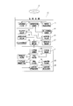
- the management device 10 includes a user registration processing unit 11, a user information storage unit 12, an identification information transmission unit 13, a user information update unit 14, a usability determination unit 15, and a usability transmission unit.
- usage information reception unit 17 usage fee calculation unit 18, usage fee unit price storage unit 19
- settlement processing unit 20 sensor information reception unit 21, sensor information storage unit 22, abnormality determination unit 23, abnormal signal transmission unit 24, operation
- the information receiving unit 25 the information analysis unit 26, the production technology information storage unit 27, the production technology request reception unit 28, and the production technology information transmission unit 29 are configured.
- the management apparatus 10 is also composed of a general computer equipped with an input device such as a keyboard and a display in addition to the CPU, ROM, and RAM.
- 20, the sensor information reception unit 21, the abnormality determination unit 23, the abnormality signal transmission unit 24, the operation information reception unit 25, the information analysis unit 26, the production technology request reception unit 28, and the production technology information transmission unit 29 are each appropriately configured by software. That function is realized.
- the user information storage unit 12, the usage fee unit price storage unit 19, the sensor information storage unit 22, and the production technology information storage unit 27 are configured by an appropriate storage medium such as a RAM.
- the user registration processing unit 11 is a functional unit that receives a registration application from the user registration application unit 113 of each use monitoring device 110 and performs a registration process for the corresponding user, and the user registration application unit 113 receives registration information transmitted from 113, stores it in the user information storage unit 12, and generates and assigns unique identification information for the user, and assigns the assigned identification information to the user information. Processing to be stored in the storage unit 12 is performed. As described above, when the machine tool 101 is installed at a specific user's place of use, the unique information of the machine tool 101 or the unique information of the use monitoring device 110 and the user's The identification information is associated with each other and stored in the user information storage unit 12.
- the user information storage unit 12 stores the usage history and payment status of each registered user. Information from the usage information receiving unit 17 and the payment processing unit 20 is stored in the user information storage unit 12. In addition, the information stored in the user information storage unit 12 is updated by the user information update unit 14 based on information input from the outside in some cases.
- the use permission determination unit 15 receives a signal related to a use permission request transmitted from a use permission processing unit 111 of each use monitoring device 110, which will be described in detail later, and permits use to a user who requests use. It is determined whether or not it is possible. Specifically, the usability determination unit 15 refers to the user information storage unit 12 to confirm the use history and the settlement status, and when inappropriate use is confirmed in the use history, and / or Alternatively, when it is confirmed that the payment is incomplete, the use is determined not to be permitted. In other cases, the user is permitted to use the machine tool 101.
- the machine tool 101 When the machine tool 101 is installed in a place used by a specific user, if the user who requests the use permission is not a user corresponding to the machine tool 101, the use is made. May not be allowed. On the other hand, even in such a case, if the user's use is allowed, the operating rate of the machine tool 101 is improved and the profit of the machine tool manufacturer is increased. The user may be allowed to use it.
- the availability determination unit 15 determines whether the user can use the user, the determination result is sent to the corresponding usage monitoring device 110 by the availability transmission unit 16. Sent.
- the usage information receiving unit 17 is a functional unit that receives the usage information transmitted from the usage information transmitting unit 118 of the usage monitoring device 110 and transfers the received usage information to the usage fee calculating unit 18.
- the usage fee calculation unit 18 calculates the usage fee of the user by referring to the usage fee unit price of each item stored in the usage fee unit price storage unit 19 based on the received usage information.
- the received usage fee is transferred to the settlement processing unit 20.
- the basic usage fee of the machine tool 101 the basic usage fee is calculated by multiplying the usage time by the unit price, and the load state of the machine tool 101, the related equipment 104, the peripheral mechanism 105, the accessory 106, etc.
- an additional usage fee is calculated according to whether or not production technology information is used, and then a total usage fee is calculated.
- the unit price may be lowered if the number of uses is large, or the unit price may be lowered as the usage time is longer, depending on the number of uses of the related equipment 104, the peripheral mechanism 105, and the accessory device 106.
- points according to usage may be given, and if a certain point is reached, some functions may be used without charge.
- the payment processing unit 20 transmits the usage fee calculated by the usage fee calculation unit 18 to the corresponding usage monitoring device 110, and performs a process for electronically paying the usage fee in cooperation with the payment processing unit 115. .
- Electronic payment is as described above.
- the sensor information receiving unit 21 is a functional unit that receives sensor information transmitted from the sensor information transmitting unit 121 of the usage monitoring device 110, stores the received sensor information in the sensor information storage unit 22, and determines whether there is an abnormality. The process of transferring to the unit 23 is performed.
- the abnormality determination unit 23 analyzes the received sensor information to determine whether or not there is an abnormality in the corresponding machine tool 101. When it is determined that there is an abnormality, the abnormality determination unit 23 passes the abnormality signal transmission unit 24. The abnormality signal is transmitted to the corresponding usage monitoring apparatus 110.
- the operation information receiving unit 25 is a functional unit that receives the operation information transmitted from the operation information transmitting unit 124 of the usage monitoring apparatus 110, and performs a process of transferring the received operation information to the information analyzing unit 26.
- the information analysis unit 26 analyzes the received operation information, extracts production technology information, edits the extracted production technology information, organizes it, and stores it in the production technology information storage unit 27. .
- the production technology request receiving unit 28 performs a process of receiving a request signal from the production technology information requesting unit 125 of the use monitoring apparatus 110 and transferring the request signal to the production technology information transmitting unit 29. With reference to the production technology information stored in the production technology information storage unit 27, the production technology information corresponding to the received request signal is read, and the read production technology information is transmitted to the corresponding usage monitoring apparatus 110. .
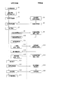
- the user uses the machine tool 101 and charges according to the use state according to the following procedure.
- step S1 when the user turns on the power switch of the machine tool 101 to be used connected to the Internet 2, the machine tool 101 and the corresponding use monitoring device 110 are activated (step S1). ). In this state, the user cannot operate the machine tool 101 yet.
- step S2 when the user inputs his / her identification information, the additional mechanism 103 to be used, the related equipment 104, the peripheral mechanism 105, and the contents (usage contents) of the accessory 106 to the use monitoring apparatus 110 (step S2),
- the input identification information and information related to use contents are transmitted from the use permission request unit 111 to the management apparatus 10 together with a signal related to the use permission request (step S3), and these are received by the usability determination unit 15.
- the usability determination unit 15 refers to the data stored in the user information storage unit 12 on the basis of the received identification information and information related to the usage content, and uses the user's usage history related to the transmitted identification information and The settlement status is confirmed (step S4). Then, when the use history is confirmed to be inappropriate and / or when the settlement is not completed, the availability determination unit 15 determines that the use is not permitted. In this case, it is determined that the user is allowed to use the machine tool 101, and a determination result regarding the availability of the machine tool 101 is sent to the usage monitoring device 110 via the availability transmission unit 16. (Step S5).
- the user registration application unit 113 of the usage monitoring device 110 and the user registration processing unit 11 of the management device 10 can process the user. On the other hand, identification information is attached and user registration is performed.
- the usage permission processing unit 112 of the usage monitoring device 110 sends the determination result to the control device of the corresponding machine tool 101 when the determination result is usable.
- a use permission signal is transmitted (step S6).
- the control device changes the operation panel from the unusable state (locked state) to the usable state (unlocked state).
- the use permission processing unit 112 displays that fact on the display.
- step S7 the user performs necessary processing using the target machine tool 101 (step S7).
- the user can use the production technology information stored in the production technology information storage unit 27 of the management device 10 via the production technology information request unit 125 of the usage monitoring device 110.
- step S8 the necessary production technology information from 125
- step S9 the production technology request receiving unit 28 of the management apparatus 10
- step S9 the production accumulated in the production technology information storage unit 27 by the production technology information transmitting unit 29
- the technical information is searched, and the requested production technical information is transmitted to the usage monitoring apparatus 110 (step S9).
- the use management apparatus 110 the transmitted production technology information is displayed on the display via the production technology information display unit 126 (step S10). Thereby, the user can use the requested production technology information.
- the usage information acquisition unit 116 of the usage management device 110 acquires the usage information from the control device of the machine tool 101, each sensor 107, related equipment 104, and the peripheral mechanism 105, Also, information related to the usage content is acquired as usage information from the usage permission processing unit 111, and the usage status of the production technology information acquired from the management apparatus 10 by the production technology information request unit 125 is acquired as usage information. Is stored in the usage information storage unit 117 (step S11).
- data (sensor information) output from each sensor 107 is stored in the sensor information storage unit 120 regularly or irregularly by the sensor information acquisition unit 119 of the usage management device 110.
- the stored sensor information is transmitted to the management apparatus 10 regularly or irregularly by the sensor information transmitting unit 121 (step S12).
- the operation information acquisition unit 122 acquires data (operation information) related to the operation state from the control device of the corresponding machine tool 101 regularly or irregularly.
- the operation information stored in the operation information storage unit 123 is transmitted to the management apparatus 10 regularly or irregularly by the operation information transmission unit 124 (step S15).
- the sensor information transmitted from the usage monitoring device 110 is received by the sensor information receiving unit 21 and stored in the sensor information storage unit 22, and the data is analyzed by the abnormality determination unit 23 to cope with it. It is determined whether there is an abnormality in the machine tool 101 to be operated. If it is determined that there is an abnormality, the abnormality signal is transmitted to the corresponding use monitoring device 110 via the abnormality signal transmission unit 24 (step). S13). Then, when an abnormal signal is transmitted from the management device 10, it is received by the abnormal signal receiving unit 127 of the corresponding usage monitoring device 110 and displayed on the display via the abnormal display unit 128 (step S14).
- the operation information transmitted from the usage monitoring apparatus 110 is received by the operation information receiving unit 25, the received operation information is analyzed by the information analysis unit 26, the production technology information is extracted, and the extracted production technology information is Edited and systematized and stored in the production technology information storage unit 27 (step S16).
- step S17 When the user finishes processing (step S17), the usage information is stored in the usage information storage unit 117 of the usage monitoring device 110, and the usage information is transmitted to the management device 10 by the usage information transmission unit 118 (step S18).
- the usage fee calculation unit 18 stores each usage information stored in the usage fee unit price storage unit 19 based on the received usage information.
- the usage fee unit price of the item is referred to, the usage fee for the user is calculated, and the calculated usage fee is transferred to the settlement processing unit 20 (step S19).
- the settlement processing unit 20 transmits the calculated usage fee to the corresponding usage monitoring apparatus 110, and in conjunction with the settlement processing unit 115, electronically settles the usage fee (step S20). After the settlement, the machine tool 101 is stopped, that is, locked. .
- the user does not need to purchase the machine tool 101, and can perform necessary processing if paying a usage fee according to use. Therefore, even when the user does not have enough work to fully operate the machine tool 101, the user can perform processing according to the work without installing the machine tool 101 newly. Can meet demand. In addition, by paying the usage fee according to the use of the machine tool 101 in this way, the user can update the existing machine tool with the state-of-the-art machine tool 101 without using capital investment, so that it is stable. Even when there is no demand or when there is a risk that the demand fluctuates suddenly, the renewal of facilities is promoted.
- machine tool manufacturers can realize stable planned production that is easy to secure profits by creating new demand that does not depend on capital investment.
- a management system is a system through the Internet 2
- the machine tool 101 can be installed overseas, for example, without being limited by the area where the machine tool 101 is installed. In this way, so-called billing processing can be performed efficiently even when installed overseas.
- the machine tool 101 having the additional mechanism 103 is adopted, and the related equipment 104, the peripheral mechanism 105, the accessory device 106, and the like are provided. As a result, the operating rate of the machine tool 101 can be improved.
- each machine tool is analyzed by analyzing the obtained data.
- the load state of 101, the performance of the machine tool 101 with respect to the load, and the like can be evaluated, and the obtained evaluation results can be used for the development and improvement of the next machine tool.
- information obtained from each sensor 107 provided in the machine tool 101 is analyzed by the abnormality determination unit 23 of the management device 10, and when it is determined that there is an abnormality, the management device 10 responds. Since an abnormality signal is transmitted to the usage monitoring device 110 and displayed on the display, the user can quickly recognize this when there is an abnormality in the machine tool 101 to be used. Therefore, the user can use the machine tool 101 with peace of mind.
- the operation information of the corresponding machine tool 101 is collected from each usage monitoring device 110, the collected operation information is analyzed by the information analysis unit 26, and the production technology information is extracted. Is compiled, systematized, and stored in the production technology information storage unit 27. Therefore, the production technology information storage unit 27 can store wide-ranging and highly reliable production technology information. Since the production technology information accumulated in this way is made available to the user, the user can perform more appropriate processing by using such production technology information. Moreover, the machine tool manufacturer can increase the profit by providing the user with the accumulated production technology information and charging a usage fee according to the use.
- the usage determination unit 15 of the management apparatus 10 confirms inappropriate use in the usage history and / or confirms that the payment is incomplete, the user determines Since use is not permitted, the system can be properly operated and its safety can be improved.
- the user is registered.
- the present invention is not necessarily limited to this, and it is possible to reliably execute the accounting process for the user and reliably perform the settlement. For example, it is not enough for user registration.
- the machine tool 101 provided with the additional mechanism is adopted, and the related equipment 104, the peripheral mechanism 105, the accessory device 106, and the sensor 107 are provided.
- the machine tool 101 may include the basic mechanism 102 as long as the usage fee can be charged according to the use state.
- the usage monitoring device 110 is provided separately from the machine tool 101.
- the configuration is not limited to such a configuration, and the usage monitoring device 110 is incorporated in the control device of the machine tool 101. It is also good.
Priority Applications (3)
| Application Number | Priority Date | Filing Date | Title |
|---|---|---|---|
| EP17871643.7A EP3540678A4 (de) | 2016-11-15 | 2017-10-17 | Verwaltungssystem für maschinenwerkzeuge |
| CN201780070352.6A CN109952591A (zh) | 2016-11-15 | 2017-10-17 | 机床管理系统 |
| US16/344,277 US20190272569A1 (en) | 2016-11-15 | 2017-10-17 | Machine Tool Management System |
Applications Claiming Priority (2)
| Application Number | Priority Date | Filing Date | Title |
|---|---|---|---|
| JP2016222093A JP6654128B2 (ja) | 2016-11-15 | 2016-11-15 | 工作機械の管理システム |
| JP2016-222093 | 2016-11-15 |
Publications (1)
| Publication Number | Publication Date |
|---|---|
| WO2018092485A1 true WO2018092485A1 (ja) | 2018-05-24 |
Family
ID=62146555
Family Applications (1)
| Application Number | Title | Priority Date | Filing Date |
|---|---|---|---|
| PCT/JP2017/037471 WO2018092485A1 (ja) | 2016-11-15 | 2017-10-17 | 工作機械の管理システム |
Country Status (5)
| Country | Link |
|---|---|
| US (1) | US20190272569A1 (de) |
| EP (1) | EP3540678A4 (de) |
| JP (1) | JP6654128B2 (de) |
| CN (1) | CN109952591A (de) |
| WO (1) | WO2018092485A1 (de) |
Families Citing this family (7)
| Publication number | Priority date | Publication date | Assignee | Title |
|---|---|---|---|---|
| CN108459563B (zh) * | 2017-02-17 | 2022-05-17 | 西门子公司 | 一种现场数据处理方法、设备和系统 |
| WO2019087546A1 (ja) * | 2017-10-30 | 2019-05-09 | ソニー株式会社 | 情報処理装置及び情報処理方法 |
| JP2020015148A (ja) * | 2018-07-26 | 2020-01-30 | 三菱マテリアル株式会社 | 切削管理システム、及び切削管理方法 |
| EP3889707A1 (de) * | 2020-03-31 | 2021-10-06 | Siemens Aktiengesellschaft | Verfahren zum ermitteln von betriebsnutzungsdaten einer industriellen vorrichtung |
| US11776379B2 (en) * | 2021-02-12 | 2023-10-03 | Parker-Hannifin Corporation | Notification system for detecting tool usage |
| WO2023095343A1 (ja) * | 2021-11-29 | 2023-06-01 | ファナック株式会社 | サービス提供装置、サービス提供システム、及びコンピュータ読み取り可能な記録媒体 |
| WO2023139708A1 (ja) * | 2022-01-19 | 2023-07-27 | ファナック株式会社 | サービス提供装置、サービス提供システム、及びコンピュータ読み取り可能な記録媒体 |
Citations (4)
| Publication number | Priority date | Publication date | Assignee | Title |
|---|---|---|---|---|
| JP2002318970A (ja) * | 2001-04-20 | 2002-10-31 | Toyoda Mach Works Ltd | 工作機械の課金装置 |
| JP2004295348A (ja) | 2003-03-26 | 2004-10-21 | Mori Seiki Co Ltd | 工作機械の保守管理システム |
| JP2004348482A (ja) * | 2003-05-22 | 2004-12-09 | Nitto Polygon Co Ltd | 事業者保有の工作機械賃貸・賃借情報交換システム |
| JP2005174008A (ja) * | 2003-12-11 | 2005-06-30 | Komatsu Ltd | 機械の料金算出システム、機械の料金算出方法、及びこの方法をコンピュータに実行させるためのプログラム |
Family Cites Families (12)
| Publication number | Priority date | Publication date | Assignee | Title |
|---|---|---|---|---|
| US7603289B2 (en) * | 2001-07-13 | 2009-10-13 | Siemens Aktiengesellschaft | System and method for electronic delivery of content for industrial automation systems |
| JP2003108254A (ja) * | 2001-09-26 | 2003-04-11 | Okaya Koki Kk | ソフトウェアのレンタルシステム並びにこれに使用するコンピュータ機器及びソフトウェア |
| JP2003168053A (ja) * | 2001-11-29 | 2003-06-13 | Chuo Sangyo Kk | 貸与機器管理システム及び貸与機器 |
| JP2003256542A (ja) * | 2002-03-05 | 2003-09-12 | Matsushita Electric Ind Co Ltd | 機器情報処理システム、機器情報処理方法、情報処理装置、機器情報処理プログラム及び制御装置 |
| US20040176965A1 (en) * | 2003-03-05 | 2004-09-09 | The Minster Machine Company | Durable goods equipment availability and usage system and method |
| CN100573374C (zh) * | 2006-09-22 | 2009-12-23 | 鸿富锦精密工业(深圳)有限公司 | 生产监控系统及方法 |
| EP2028439A1 (de) * | 2007-07-26 | 2009-02-25 | Renishaw plc | Abschaltbares Messgerät |
| CN101944242A (zh) * | 2010-08-06 | 2011-01-12 | 西北工业大学 | 普通机床有效工作时间记录仪 |
| EP2476511B1 (de) * | 2011-01-14 | 2013-03-27 | ARTIS GmbH | Vorrichtung und Verfahren zum Überwachen einer Werkzeugmaschine |
| CN203455669U (zh) * | 2013-09-16 | 2014-02-26 | 南京工程学院 | 基于嵌入式系统的数控机床可视化能效管理监测平台 |
| TWI501060B (zh) * | 2013-11-18 | 2015-09-21 | Inst Information Industry | 稼動率計算方法及其系統、嵌入式裝置和電腦可讀取儲存媒體 |
| CN104539677A (zh) * | 2014-12-19 | 2015-04-22 | 华南理工大学 | 一种基于物联网的数控机床共享系统及方法 |
-
2016
- 2016-11-15 JP JP2016222093A patent/JP6654128B2/ja active Active
-
2017
- 2017-10-17 US US16/344,277 patent/US20190272569A1/en not_active Abandoned
- 2017-10-17 EP EP17871643.7A patent/EP3540678A4/de active Pending
- 2017-10-17 WO PCT/JP2017/037471 patent/WO2018092485A1/ja unknown
- 2017-10-17 CN CN201780070352.6A patent/CN109952591A/zh active Pending
Patent Citations (4)
| Publication number | Priority date | Publication date | Assignee | Title |
|---|---|---|---|---|
| JP2002318970A (ja) * | 2001-04-20 | 2002-10-31 | Toyoda Mach Works Ltd | 工作機械の課金装置 |
| JP2004295348A (ja) | 2003-03-26 | 2004-10-21 | Mori Seiki Co Ltd | 工作機械の保守管理システム |
| JP2004348482A (ja) * | 2003-05-22 | 2004-12-09 | Nitto Polygon Co Ltd | 事業者保有の工作機械賃貸・賃借情報交換システム |
| JP2005174008A (ja) * | 2003-12-11 | 2005-06-30 | Komatsu Ltd | 機械の料金算出システム、機械の料金算出方法、及びこの方法をコンピュータに実行させるためのプログラム |
Non-Patent Citations (1)
| Title |
|---|
| See also references of EP3540678A4 |
Also Published As
| Publication number | Publication date |
|---|---|
| JP6654128B2 (ja) | 2020-02-26 |
| EP3540678A1 (de) | 2019-09-18 |
| EP3540678A4 (de) | 2020-05-06 |
| CN109952591A (zh) | 2019-06-28 |
| JP2018081399A (ja) | 2018-05-24 |
| US20190272569A1 (en) | 2019-09-05 |
Similar Documents
| Publication | Publication Date | Title |
|---|---|---|
| WO2018092485A1 (ja) | 工作機械の管理システム | |
| KR101711237B1 (ko) | 컴퓨터 네트워크의 서버 | |
| EP1852760B1 (de) | Tragbares Werkzeug | |
| CN103459078B (zh) | 焊接型系统以及用成本计算器计算焊接操作成本的方法 | |
| US20150142154A1 (en) | Modular system for real-time evaluation and monitoring of a machining production-line overall performances calculated from each given workpiece, tool and machine | |
| CN101689313A (zh) | 视觉诊断系统和定制服务 | |
| KR20080016918A (ko) | 작업성 관리 시스템, 방법 및 프로그램, 작업 관리 시스템,방법 및 장치, 및 피킹 대차 | |
| JP2011526545A (ja) | 製造環境において、消耗品を監視し、制御し、及び取り出すためのシステム及び方法 | |
| JP4876528B2 (ja) | 工作機械における部品寿命管理システム | |
| JPH1124744A (ja) | 移動式作業機械管理システム及び管理方法並びに同管理システムのための移動式作業機械,ユーザ装置及び親装置 | |
| CN101587572A (zh) | 制造指示评价支持系统、制造指示评价支持方法 | |
| JP4893723B2 (ja) | 工作機械における部品寿命管理システム | |
| US11156990B2 (en) | Production management system | |
| CN105807718A (zh) | 具有本征功能性检测的制造机器和方法 | |
| CN113721575A (zh) | 一种刀具寿命智能化监控系统及方法 | |
| Eversheim et al. | Design-to-cost for production systems | |
| KR101815241B1 (ko) | 지능형 통합 공구관리시스템 | |
| JP2004348482A (ja) | 事業者保有の工作機械賃貸・賃借情報交換システム | |
| Hubbard et al. | A standardized model for the evaluation of machining coolant/lubricant costs | |
| KR102012341B1 (ko) | 시앤시 가공시간 예측 디지털 경광등 | |
| JP2002318970A (ja) | 工作機械の課金装置 | |
| JP2002032498A (ja) | 電子的生産システム、および生産情報の供給方法並びに生産情報の登録方法 | |
| WO2000011582A1 (fr) | Procede et appareil permettant de determiner la balance des operations effectuees par des machines | |
| JP7252031B2 (ja) | 工作機械管理システム、管理装置、および工作機械に接続される接続装置 | |
| WO2023095343A9 (ja) | サービス提供装置、サービス提供システム、及びコンピュータ読み取り可能な記録媒体 |
Legal Events
| Date | Code | Title | Description |
|---|---|---|---|
| 121 | Ep: the epo has been informed by wipo that ep was designated in this application |
Ref document number: 17871643 Country of ref document: EP Kind code of ref document: A1 |
|
| NENP | Non-entry into the national phase |
Ref country code: DE |
|
| ENP | Entry into the national phase |
Ref document number: 2017871643 Country of ref document: EP Effective date: 20190617 |