WO2018092438A1 - 制御モジュール - Google Patents
制御モジュール Download PDFInfo
- Publication number
- WO2018092438A1 WO2018092438A1 PCT/JP2017/035801 JP2017035801W WO2018092438A1 WO 2018092438 A1 WO2018092438 A1 WO 2018092438A1 JP 2017035801 W JP2017035801 W JP 2017035801W WO 2018092438 A1 WO2018092438 A1 WO 2018092438A1
- Authority
- WO
- WIPO (PCT)
- Prior art keywords
- control
- refrigerant
- air
- heat exchanger
- control device
- Prior art date
Links
Images


Classifications
-
- B—PERFORMING OPERATIONS; TRANSPORTING
- B60—VEHICLES IN GENERAL
- B60H—ARRANGEMENTS OF HEATING, COOLING, VENTILATING OR OTHER AIR-TREATING DEVICES SPECIALLY ADAPTED FOR PASSENGER OR GOODS SPACES OF VEHICLES
- B60H1/00—Heating, cooling or ventilating [HVAC] devices
- B60H1/32—Cooling devices
- B60H1/3204—Cooling devices using compression
- B60H1/3205—Control means therefor
- B60H1/3213—Control means therefor for increasing the efficiency in a vehicle heat pump
-
- B—PERFORMING OPERATIONS; TRANSPORTING
- B60—VEHICLES IN GENERAL
- B60H—ARRANGEMENTS OF HEATING, COOLING, VENTILATING OR OTHER AIR-TREATING DEVICES SPECIALLY ADAPTED FOR PASSENGER OR GOODS SPACES OF VEHICLES
- B60H1/00—Heating, cooling or ventilating [HVAC] devices
- B60H1/32—Cooling devices
- B60H1/3204—Cooling devices using compression
- B60H1/3227—Cooling devices using compression characterised by the arrangement or the type of heat exchanger, e.g. condenser, evaporator
-
- B—PERFORMING OPERATIONS; TRANSPORTING
- B60—VEHICLES IN GENERAL
- B60K—ARRANGEMENT OR MOUNTING OF PROPULSION UNITS OR OF TRANSMISSIONS IN VEHICLES; ARRANGEMENT OR MOUNTING OF PLURAL DIVERSE PRIME-MOVERS IN VEHICLES; AUXILIARY DRIVES FOR VEHICLES; INSTRUMENTATION OR DASHBOARDS FOR VEHICLES; ARRANGEMENTS IN CONNECTION WITH COOLING, AIR INTAKE, GAS EXHAUST OR FUEL SUPPLY OF PROPULSION UNITS IN VEHICLES
- B60K11/00—Arrangement in connection with cooling of propulsion units
- B60K11/02—Arrangement in connection with cooling of propulsion units with liquid cooling
- B60K11/04—Arrangement or mounting of radiators, radiator shutters, or radiator blinds
-
- F—MECHANICAL ENGINEERING; LIGHTING; HEATING; WEAPONS; BLASTING
- F25—REFRIGERATION OR COOLING; COMBINED HEATING AND REFRIGERATION SYSTEMS; HEAT PUMP SYSTEMS; MANUFACTURE OR STORAGE OF ICE; LIQUEFACTION SOLIDIFICATION OF GASES
- F25B—REFRIGERATION MACHINES, PLANTS OR SYSTEMS; COMBINED HEATING AND REFRIGERATION SYSTEMS; HEAT PUMP SYSTEMS
- F25B49/00—Arrangement or mounting of control or safety devices
- F25B49/02—Arrangement or mounting of control or safety devices for compression type machines, plants or systems
-
- F—MECHANICAL ENGINEERING; LIGHTING; HEATING; WEAPONS; BLASTING
- F25—REFRIGERATION OR COOLING; COMBINED HEATING AND REFRIGERATION SYSTEMS; HEAT PUMP SYSTEMS; MANUFACTURE OR STORAGE OF ICE; LIQUEFACTION SOLIDIFICATION OF GASES
- F25D—REFRIGERATORS; COLD ROOMS; ICE-BOXES; COOLING OR FREEZING APPARATUS NOT OTHERWISE PROVIDED FOR
- F25D21/00—Defrosting; Preventing frosting; Removing condensed or defrost water
- F25D21/06—Removing frost
- F25D21/12—Removing frost by hot-fluid circulating system separate from the refrigerant system
-
- B—PERFORMING OPERATIONS; TRANSPORTING
- B60—VEHICLES IN GENERAL
- B60H—ARRANGEMENTS OF HEATING, COOLING, VENTILATING OR OTHER AIR-TREATING DEVICES SPECIALLY ADAPTED FOR PASSENGER OR GOODS SPACES OF VEHICLES
- B60H1/00—Heating, cooling or ventilating [HVAC] devices
- B60H1/00642—Control systems or circuits; Control members or indication devices for heating, cooling or ventilating devices
- B60H1/00814—Control systems or circuits characterised by their output, for controlling particular components of the heating, cooling or ventilating installation
- B60H1/00878—Control systems or circuits characterised by their output, for controlling particular components of the heating, cooling or ventilating installation the components being temperature regulating devices
- B60H1/00885—Controlling the flow of heating or cooling liquid, e.g. valves or pumps
-
- B—PERFORMING OPERATIONS; TRANSPORTING
- B60—VEHICLES IN GENERAL
- B60H—ARRANGEMENTS OF HEATING, COOLING, VENTILATING OR OTHER AIR-TREATING DEVICES SPECIALLY ADAPTED FOR PASSENGER OR GOODS SPACES OF VEHICLES
- B60H1/00—Heating, cooling or ventilating [HVAC] devices
- B60H1/32—Cooling devices
- B60H2001/3236—Cooling devices information from a variable is obtained
- B60H2001/3266—Cooling devices information from a variable is obtained related to the operation of the vehicle
-
- B—PERFORMING OPERATIONS; TRANSPORTING
- B60—VEHICLES IN GENERAL
- B60H—ARRANGEMENTS OF HEATING, COOLING, VENTILATING OR OTHER AIR-TREATING DEVICES SPECIALLY ADAPTED FOR PASSENGER OR GOODS SPACES OF VEHICLES
- B60H1/00—Heating, cooling or ventilating [HVAC] devices
- B60H1/32—Cooling devices
- B60H2001/3236—Cooling devices information from a variable is obtained
- B60H2001/3267—Cooling devices information from a variable is obtained related to the operation of an expansion valve
-
- B—PERFORMING OPERATIONS; TRANSPORTING
- B60—VEHICLES IN GENERAL
- B60H—ARRANGEMENTS OF HEATING, COOLING, VENTILATING OR OTHER AIR-TREATING DEVICES SPECIALLY ADAPTED FOR PASSENGER OR GOODS SPACES OF VEHICLES
- B60H1/00—Heating, cooling or ventilating [HVAC] devices
- B60H1/32—Cooling devices
- B60H2001/3269—Cooling devices output of a control signal
- B60H2001/3285—Cooling devices output of a control signal related to an expansion unit
-
- F—MECHANICAL ENGINEERING; LIGHTING; HEATING; WEAPONS; BLASTING
- F25—REFRIGERATION OR COOLING; COMBINED HEATING AND REFRIGERATION SYSTEMS; HEAT PUMP SYSTEMS; MANUFACTURE OR STORAGE OF ICE; LIQUEFACTION SOLIDIFICATION OF GASES
- F25B—REFRIGERATION MACHINES, PLANTS OR SYSTEMS; COMBINED HEATING AND REFRIGERATION SYSTEMS; HEAT PUMP SYSTEMS
- F25B13/00—Compression machines, plants or systems, with reversible cycle
-
- F—MECHANICAL ENGINEERING; LIGHTING; HEATING; WEAPONS; BLASTING
- F25—REFRIGERATION OR COOLING; COMBINED HEATING AND REFRIGERATION SYSTEMS; HEAT PUMP SYSTEMS; MANUFACTURE OR STORAGE OF ICE; LIQUEFACTION SOLIDIFICATION OF GASES
- F25B—REFRIGERATION MACHINES, PLANTS OR SYSTEMS; COMBINED HEATING AND REFRIGERATION SYSTEMS; HEAT PUMP SYSTEMS
- F25B2600/00—Control issues
- F25B2600/11—Fan speed control
- F25B2600/111—Fan speed control of condenser fans
-
- F—MECHANICAL ENGINEERING; LIGHTING; HEATING; WEAPONS; BLASTING
- F25—REFRIGERATION OR COOLING; COMBINED HEATING AND REFRIGERATION SYSTEMS; HEAT PUMP SYSTEMS; MANUFACTURE OR STORAGE OF ICE; LIQUEFACTION SOLIDIFICATION OF GASES
- F25B—REFRIGERATION MACHINES, PLANTS OR SYSTEMS; COMBINED HEATING AND REFRIGERATION SYSTEMS; HEAT PUMP SYSTEMS
- F25B2600/00—Control issues
- F25B2600/25—Control of valves
- F25B2600/2513—Expansion valves
-
- F—MECHANICAL ENGINEERING; LIGHTING; HEATING; WEAPONS; BLASTING
- F25—REFRIGERATION OR COOLING; COMBINED HEATING AND REFRIGERATION SYSTEMS; HEAT PUMP SYSTEMS; MANUFACTURE OR STORAGE OF ICE; LIQUEFACTION SOLIDIFICATION OF GASES
- F25B—REFRIGERATION MACHINES, PLANTS OR SYSTEMS; COMBINED HEATING AND REFRIGERATION SYSTEMS; HEAT PUMP SYSTEMS
- F25B2700/00—Sensing or detecting of parameters; Sensors therefor
- F25B2700/21—Temperatures
- F25B2700/2106—Temperatures of fresh outdoor air
-
- F—MECHANICAL ENGINEERING; LIGHTING; HEATING; WEAPONS; BLASTING
- F25—REFRIGERATION OR COOLING; COMBINED HEATING AND REFRIGERATION SYSTEMS; HEAT PUMP SYSTEMS; MANUFACTURE OR STORAGE OF ICE; LIQUEFACTION SOLIDIFICATION OF GASES
- F25B—REFRIGERATION MACHINES, PLANTS OR SYSTEMS; COMBINED HEATING AND REFRIGERATION SYSTEMS; HEAT PUMP SYSTEMS
- F25B41/00—Fluid-circulation arrangements
- F25B41/20—Disposition of valves, e.g. of on-off valves or flow control valves
Definitions
- the present disclosure relates to a control module that controls a heat exchange unit provided in a vehicle.
- the vehicle is equipped with multiple heat exchangers.
- a heat exchanger include a radiator for exchanging heat between cooling water for an internal combustion engine and air, and outdoor heat for exchanging heat between a refrigerant for air conditioning and air.
- An exchange etc. are mentioned.
- Some of the plurality of heat exchangers are often united as a whole and configured as a heat exchange unit.
- the heat exchange unit is disposed in the front portion of the vehicle in a state where a plurality of heat exchangers are stacked along the air flow direction.
- the flow of the refrigerant passing through the heat exchange unit is adjusted so that the vehicle air conditioner provided in the vehicle exhibits a desired performance.
- Such adjustment of the refrigerant flow is performed by, for example, an air conditioning ECU provided for air conditioning control controlling the rotation speed of the compressor, the opening degree of the electric expansion valve, and the like in the refrigeration cycle.
- the flow of the cooling water passing through the heat exchange unit is adjusted so that the temperature of the internal combustion engine provided in the vehicle is maintained at an appropriate temperature.
- Such adjustment of the cooling water flow is performed by an engine ECU provided for controlling the internal combustion engine controlling the number of rotations of a water pump that sends out cooling water, the operation of a switching valve for switching the flow path, and the like. Done.
- Patent Document 1 shows an example of a heat exchange unit configured to control operations by an air conditioning ECU (air conditioning control unit) and an engine ECU (engine control unit) as described above. .
- the heat exchanger unit requires a plurality of devices for adjusting the flow of each of the three fluids (refrigerant, cooling water, and air).
- the operations of these devices are not performed separately but linked to each other. It is desirable to be done as follows.
- an air conditioning ECU that mainly controls the flow of refrigerant and an engine that mainly controls the flow of cooling water in order to achieve the above-described interlocking. It is necessary to perform bidirectional communication with the ECU. However, when a delay in communication between ECUs occurs, various devices that control the fluid do not operate at an appropriate timing. As a result, for example, a situation may occur in which the refrigerant pressure increases excessively due to an inappropriate shutter opening at a specific point in time, and the compressor suddenly stops.
- An object of the present disclosure is to provide a control module that can appropriately link the operations of a plurality of devices for adjusting the flow of refrigerant, cooling water, and air in a heat exchange unit.
- the control module is a control module that controls a heat exchange unit provided in a vehicle.
- the heat exchange unit includes a first heat exchanger that exchanges heat between air-conditioning refrigerant and air, a second heat exchanger that exchanges heat between cooling water and air, and a refrigerant that passes through the first heat exchanger.
- a refrigerant control device that is a device for adjusting the flow of the refrigerant
- a cooling water control device that is a device for adjusting the flow of cooling water passing through the second heat exchanger, the first heat exchanger, and the second heat exchange
- an air control device that is a device for adjusting the flow of air through the vessel.
- the control module receives a control signal for controlling the operation of at least one of the refrigerant control device, the cooling water control device, and the air control device from at least one electronic control unit provided in the vehicle. And a control unit that performs interlock control for operating at least two of the refrigerant control device, the cooling water control device, and the air control device in conjunction with each other based on the control signal.
- the operation of at least a part of the refrigerant control device, the cooling water control device, and the air control device is an electronic control unit (ECU) provided in the vehicle. This is done directly through the control module.
- the control unit of the control module performs interlock control that causes at least two of the refrigerant control device, the cooling water control device, and the air control device to operate in conjunction with each other based on a control signal from the electronic control unit.
- the control module can grasp the three fluid states relatively accurately in the heat exchange unit, compared to an air conditioning ECU that considers only the operation of the vehicle air conditioner and an engine ECU that considers only the operation of the internal combustion engine. It can be done. Since the control unit of such a control module performs interlocking control instead of the air conditioning ECU or the like, the flow of various fluids can be adjusted more appropriately. Furthermore, since the operation timing of various devices is not shifted due to a communication delay between ECUs, more appropriate control can be realized.
- control module that can appropriately link the operations of a plurality of devices for adjusting the flow of refrigerant, cooling water, and air in the heat exchange unit.
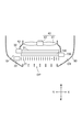
- FIG. 1 is a diagram schematically illustrating a state in which a heat exchange unit including a control module according to the first embodiment is mounted on a vehicle.
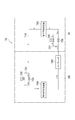
- FIG. 2 is a diagram schematically illustrating the heat exchange unit of FIG. 1 as viewed from above.
- FIG. 3 is a diagram showing an overall configuration of a vehicle air conditioner mounted on the vehicle.
- FIG. 4 is a diagram illustrating the configuration of the outdoor heat exchanger and the electric expansion valve in the vehicle air conditioner of FIG. 3.
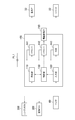
- FIG. 5 is a block diagram schematically showing the heat exchange unit and the surrounding configuration.
- FIG. 6 is a block diagram schematically showing the internal configuration of the control module.
- FIG. 7 is a flowchart showing the flow of processing executed by the control unit of the control module.
- FIG. 8 is a diagram illustrating a configuration of an outdoor heat exchanger, an electric expansion valve, and an electric fan in the heat exchange unit according to the second embodiment.
- FIG. 9 is a block diagram schematically showing the heat exchange unit and the surrounding configuration.
- FIG. 10 is a block diagram schematically showing the internal configuration of the control module.
- the control module 100 is configured as a device for controlling the heat exchange unit 10 provided in the vehicle 50.
- the configuration of the heat exchange unit 10 will be described first.
- the heat exchange unit 10 is a unit obtained by combining a plurality of heat exchangers (the outdoor heat exchanger 740 and the radiator 31).
- the heat exchange unit 10 is installed in the engine room ER of the vehicle 50.
- the outdoor heat exchanger 740 is a part of a vehicle air conditioner 70 (see FIG. 3) described later.
- the outdoor heat exchanger 740 is configured as a heat exchanger for performing heat exchange between the air introduced into the engine room ER from the opening OP of the front grille and the refrigerant circulating in the vehicle air conditioner 70. Has been.
- the outdoor heat exchanger 740 corresponds to the “first heat exchanger” in the present embodiment.
- the radiator 31 is a heat exchanger for cooling the cooling water circulating through the engine 51, which is an internal combustion engine, by heat exchange with air.
- the radiator 31 is disposed at a position on the rear side of the outdoor heat exchanger 740. For this reason, the air introduced into the engine room ER from the opening OP of the front grill is provided for heat exchange with the refrigerant through the outdoor heat exchanger 740 as described above, and then cooled through the radiator 31. It is used for heat exchange with water.
- the radiator 31 corresponds to the “second heat exchanger” in the present embodiment.
- the heat exchange unit 10 includes a shutter 21, an electric fan 40, a shroud 43, an electric expansion valve 730, and a hot water valve 32 in addition to the radiator 31 and the outdoor heat exchanger 740.
- the shutter 21 is a device for adjusting the flow rate of air introduced into the engine room ER from the opening OP, and is called a so-called grill shutter.
- the shutter 21 is disposed at a position on the front side of the outdoor heat exchanger 740. When the opening degree of the shutter 21 changes, the flow rate of air passing through each of the outdoor heat exchanger 740 and the radiator 31 changes.
- a shutter actuator 22 is provided in the vicinity of the shutter 21.
- the shutter actuator 22 is an electric drive device for adjusting the opening degree of the shutter 21.
- the operation of the shutter actuator 22 is controlled by the control module 100 described later.
- the shutter 21 and the shutter actuator 22 are devices for adjusting the air flow through the outdoor heat exchanger 740 (first heat exchanger) and the radiator 31 (second heat exchanger). This corresponds to the “air control device” in the present embodiment.
- the electric fan 40 is an electric fan for creating a flow of air that passes through the outdoor heat exchanger 740 and the radiator 31.
- the electric fan 40 is arranged at a position on the rear side of the radiator 31.
- the electric fan 40 includes a rotating blade 41 for creating an air flow and a fan motor 42 that is a rotating electric machine for rotating the rotating blade 41.
- a fan motor 42 that is a rotating electric machine for rotating the rotating blade 41.
- the shroud 43 is a member provided to cover the periphery of the electric fan 40 from the rear side. The air drawn by the electric fan 40 is efficiently guided to the outdoor heat exchanger 740 and the radiator 31 by the shroud 43.
- the electric expansion valve 730 is a device that forms part of the vehicle air conditioner 70 together with the outdoor heat exchanger 740. As will be described later, the electric expansion valve 730 functions as an expansion valve that reduces the pressure of the refrigerant in the refrigeration cycle. The opening degree of the electric expansion valve 730 is controlled by the control module 100. The electric expansion valve 730 adjusts the flow of the refrigerant that circulates along the path passing through the outdoor heat exchanger 740. Such an electric expansion valve 730 corresponds to the “refrigerant control device” in the present embodiment.
- the hot water valve 32 is an electric on-off valve provided in the middle of a flow path (not shown) through which cooling water circulates between the radiator 31 and the engine 51.
- the hot water valve 32 is provided at a position adjacent to the radiator 31. When the hot water valve 32 is closed, the supply of cooling water to the radiator 31 is stopped. The operation of the hot water valve 32 is controlled by the control module 100.
- Such a hot water valve 32 is a device for adjusting the flow of cooling water passing through the radiator 31 (second heat exchanger), and corresponds to the “cooling water control device” in the present embodiment.
- the configuration of the vehicle air conditioner 70 will be described with reference to FIG.
- the vehicle air conditioner 70 is configured as a refrigeration cycle in which refrigerant circulates.
- the vehicle air conditioner 70 includes a refrigerant flow path 710, a compressor 720, an electric expansion valve 750, an indoor heat exchanger 760, an electric expansion valve 730, and an outdoor heat exchanger 740.
- a part of the vehicle air conditioner 70 (outdoor heat exchanger 740 etc.) is arranged in the engine room ER of the vehicle 50, and the other part (indoor heat exchanger 760 etc.). ) Is disposed in the cabin IR of the vehicle 50.
- the refrigerant flow path 710 is a pipe arranged in an annular shape to circulate the refrigerant. All of the compressors 720 and the like described below are arranged along the refrigerant flow path 710.
- the compressor 720 is a device for pumping the refrigerant and circulating it in the refrigerant flow path 710.
- the compressor 720 is being driven, the refrigerant that has been compressed in the compressor 720 and becomes high temperature and pressure is sent out toward the electric expansion valve 750 side.
- the electric expansion valve 750 is provided at a position downstream of the compressor 720 in the refrigerant flow path 710.
- the electric expansion valve 750 reduces the pressure of the refrigerant passing therethrough by reducing the flow passage cross-sectional area of the refrigerant flow passage 710 at the position.
- the electric expansion valve 750 operates a valve body (not shown) by an electric actuator (not shown) and changes its opening degree.
- a bypass flow path 751 for flowing the refrigerant so as to bypass the electric expansion valve 750 is provided at a position near the electric expansion valve 750.
- An electromagnetic on-off valve 752 is provided in the middle of the bypass flow path 751.
- the electromagnetic open / close valve 752 When the electromagnetic open / close valve 752 is in the closed state, the refrigerant circulates through the refrigerant flow path 710 through a path passing through the electric expansion valve 750.
- the electromagnetic on-off valve 752 When the electromagnetic on-off valve 752 is in the open state, the refrigerant hardly circulates through the electric expansion valve 750 and circulates through the refrigerant flow path 710 along a path passing through the bypass flow path 751.
- the indoor heat exchanger 760 is provided at a position downstream of the electric expansion valve 750 in the refrigerant flow path 710.
- the indoor heat exchanger 760 is a heat exchanger for exchanging heat between the air blown into the passenger compartment IR and the refrigerant circulating in the refrigerant flow path 710.
- the vehicle air conditioner 70 performs air conditioning in the passenger compartment IR by heating or cooling air in the indoor heat exchanger 760.
- the electric expansion valve 730 forms a part of the heat exchange unit 10 as described above, and is provided in the refrigerant channel 710 at a position downstream of the indoor heat exchanger 760.
- the electric expansion valve 730 reduces the pressure of the refrigerant passing therethrough by reducing the flow passage cross-sectional area of the refrigerant flow passage 710 at the position.
- the electric expansion valve 730 operates a valve body (not shown) by an electric actuator 730M (not shown in FIG. 3, see FIG. 4), and changes its opening degree.
- a bypass flow path 731 for flowing the refrigerant so as to bypass the electric expansion valve 730 is provided at a position near the electric expansion valve 730.
- An electromagnetic on-off valve 732 is provided in the middle of the bypass flow path 731.
- the electromagnetic on-off valve 732 When the electromagnetic on-off valve 732 is in the closed state, the refrigerant circulates through the refrigerant flow path 710 through a path that passes through the electric expansion valve 730.
- the electromagnetic open / close valve 732 When the electromagnetic open / close valve 732 is in the open state, the refrigerant hardly circulates through the electric expansion valve 730 and circulates through the refrigerant flow path 710 through a path passing through the bypass flow path 731.
- the outdoor heat exchanger 740 is a part of the heat exchange unit 10 as described above.
- the outdoor heat exchanger 740 is provided at a position downstream of the electric expansion valve 730 in the refrigerant flow path 710 and upstream of the compressor 720. A specific configuration of the outdoor heat exchanger 740 will be described later.
- the electromagnetic open / close valve 732 When the vehicle interior IR is heated by the vehicle air conditioner 70, the electromagnetic open / close valve 732 is switched to the closed state, and the electromagnetic open / close valve 752 is switched to the open state.
- the refrigerant circulates through the refrigerant flow path 710 along a path that passes through the electric expansion valve 730, and reduces its temperature and pressure when passing through the electric expansion valve 730. That is, when the interior of the passenger compartment IR is heated, the electric expansion valve 730 functions as an “expansion valve” of the refrigeration cycle.
- the low-temperature and low-pressure refrigerant that has passed through the electric expansion valve 730 is supplied to the outdoor heat exchanger 740.
- the outdoor heat exchanger 740 heat is absorbed from the air by the low-temperature refrigerant, and the refrigerant evaporates. That is, when the interior of the passenger compartment IR is heated, the outdoor heat exchanger 740 functions as an “evaporator” of the refrigeration cycle.
- the refrigerant that has passed through the outdoor heat exchanger 740 is compressed by the compressor 720, and is sent downstream with its temperature and pressure increased.
- the high-temperature and high-pressure refrigerant is supplied to the indoor heat exchanger 760 through the bypass channel 751.
- the indoor heat exchanger 760 In the indoor heat exchanger 760, heat is released from the refrigerant to the air, thereby condensing the refrigerant. That is, when the interior of the passenger compartment IR is heated, the indoor heat exchanger 760 functions as a “condenser” for the refrigeration cycle. After the temperature of the air is increased by heat exchange in the indoor heat exchanger 760, the air is blown into the passenger compartment IR as conditioned air.
- the refrigerant that has passed through the indoor heat exchanger 760 passes through the refrigerant flow path 710 and reaches the electric expansion valve 730 again.
- coolant circulates as mentioned above when the inside of vehicle interior IR is performed is shown by the some arrow.
- the electromagnetic on-off valve 732 When the vehicle interior IR is cooled by the vehicle air conditioner 70, the electromagnetic on-off valve 732 is switched to the open state, and the electromagnetic on-off valve 752 is switched to the closed state. In this state, the refrigerant circulating in the refrigerant flow path 710 flows through the electric expansion valve 730 while passing through the electric expansion valve 750. The refrigerant reduces its temperature and pressure when passing through the electric expansion valve 750. In other words, when the passenger compartment IR is cooled, the electric expansion valve 750 functions as an “expansion valve” of the refrigeration cycle.
- the low-temperature and low-pressure refrigerant that has passed through the electric expansion valve 730 is supplied to the indoor heat exchanger 760.
- the indoor heat exchanger 760 heat is absorbed from the air by the low-temperature refrigerant, whereby the refrigerant evaporates. That is, when the passenger compartment IR is cooled, the indoor heat exchanger 760 functions as an “evaporator” of the refrigeration cycle.
- the outdoor heat exchanger 740 heat is radiated from the refrigerant to the air. That is, when the passenger compartment IR is heated, the outdoor heat exchanger 740 functions as a “condenser” for the refrigeration cycle. At this time, the refrigerant flow path is changed in advance by a pipe, a switching valve, or the like (not shown) so that the refrigerant is compressed by the compressor 720 not on the downstream side of the outdoor heat exchanger 740 but on the upstream side. It is good also as a structure.
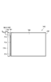
- the outdoor heat exchanger 740 includes a pair of tanks 741 and 742 and a core portion 743 disposed therebetween.
- Each of the tanks 741 and 742 is an elongated container formed to extend in the vertical direction.
- the refrigerant circulating in the refrigerant flow path 710 is temporarily stored.
- the core part 743 is a part where heat is exchanged between the refrigerant and air in the outdoor heat exchanger 740.
- a plurality of tubes and fins are arranged on the core portion 743.
- the tube is, for example, a tube having a flat cross section, and a flow path through which the refrigerant passes is formed in the tube.
- Each of the plurality of tubes connects between the tank 741 and the tank 742, and is arranged so as to be stacked up and down with their main surfaces facing each other.
- the fins are formed by bending a metal plate into a wave shape, and are arranged between the stacked tubes.
- the top of each of the undulating fins is in contact with the outer surface of the tube and brazed. For this reason, the heat of the air passing through the outdoor heat exchanger 740 during heating is not only transmitted to the refrigerant via the tube, but also transmitted to the refrigerant via the fins and the tube. That is, the contact area with the air is increased by the fins, and heat exchange between the refrigerant and the air is performed efficiently.
- adopted as a structure of the core part 743 which has the above fins and tubes it abbreviate
- the internal spaces of the tank 741 and the tank 742 are partitioned so as to be divided up and down by a separator (not shown).
- the refrigerant passing through the outdoor heat exchanger 740 is used for heat exchange in the core portion 743 while going back and forth between the tank 741 and the tank 742 a plurality of times.
- a modulator tank 770 is provided on the side of the tank 741 (the side opposite to the core portion 743).
- the modulator tank 770 is an elongated container formed so as to extend in the vertical direction, and is arranged in parallel with the tank 741.
- the modulator tank 770 and the tank 741 are connected by connection pipes 771, 772, and 773.
- the refrigerant passing through the outdoor heat exchanger 740 goes back and forth between the tank 741 and the tank 742 a plurality of times through the modulator tank 770 from the connection pipes 771, 772, and 773.
- the modulator tank 770 stores a liquid phase refrigerant.
- the refrigerant flowing in the gas-liquid mixed state is in a state where the gas and liquid are separated when passing through the modulator tank 770.
- the electric actuator 730M of the electric expansion valve 730 is attached to the upper end of the modulator tank 770. Thereby, the electric expansion valve 730 and the modulator tank 770 are integrated.
- a valve body (not shown) for reducing the cross-sectional area of the flow path in the electric expansion valve 730 is provided at a position directly below the electric actuator 730M, and is disposed inside the modulator tank 770.
- the electric actuator 730M is provided with a circuit board BD1 for operating the electric actuator 730M.
- the components of the control module 100 are also arranged on the circuit board BD1. That is, the control module 100 according to the present embodiment is configured integrally with the electric expansion valve 730 that is a refrigerant control device.
- the heat exchange unit 10 including the control module 100 and the surrounding configuration will be described with reference to FIG. As already described, the heat exchange unit 10 is entirely disposed in the engine room ER of the vehicle 50.
- a plurality of sensors necessary for controlling the flow of the three fluids (refrigerant, cooling water, air) in the heat exchange unit 10 are arranged.
- sensors include a pressure sensor that measures the pressure of the refrigerant in each part of the refrigerant flow path 710, a temperature sensor that measures the temperature of the refrigerant in each part, and an opening sensor that measures the opening of the shutter 21. Can be mentioned.
- the value measured by each sensor is input to the control module 100 as an electrical signal (detection signal).
- these multiple sensors are depicted as a single block labeled 60.
- the plurality of sensors are collectively referred to as “sensor 60”.
- an engine ECU 200 and an air conditioning ECU 300 are arranged in the passenger compartment IR of the vehicle 50. These are all configured as a computer system having a CPU, a ROM, a RAM, a communication interface, and the like.
- the engine ECU 200 and the air conditioning ECU 300 both correspond to the “electronic control unit” in the present embodiment.
- the engine ECU 200 is a control device for controlling the engine 51.
- the engine ECU 200 adjusts the flow rate of the cooling water circulating between the engine 51 and the radiator 31, controls the operation of the hot water valve 32, adjusts the opening degree of the shutter 21, adjusts the rotation speed of the electric fan 40, and the like.
- a part of the control performed by the engine ECU 200 (for example, the operation control of the shutter actuator 22) is performed via the control module 100.
- the control module 100 receives a control signal transmitted from the engine ECU 200, and controls operations of various devices (such as the shutter actuator 22) based on the control signal.
- various devices such as the shutter actuator 22
- the control module 100 does not always perform operation control of various devices according to the control signal, but may perform control different from the control indicated by the control signal. Details will be described later.
- the air conditioning ECU 300 is a control device for controlling the vehicle air conditioner 70.
- the air conditioning ECU 300 appropriately performs air conditioning in the passenger compartment IR by controlling the operations of various devices (electric expansion valve 730) constituting the vehicle air conditioner 70.
- a part of the control performed by the air conditioning ECU 300 (for example, operation control of the electric expansion valve 730) is performed via the control module 100.
- the control module 100 receives a control signal transmitted from the air conditioning ECU 300, and performs operation control of various devices (such as the electric expansion valve 730) based on the control signal.
- various devices such as the electric expansion valve 730
- the control module 100 does not always perform operation control of various devices according to the control signal, but may perform control different from the control indicated by the control signal. Details will be described later.
- the vehicle 50 is provided with a plurality of power supply systems for supplying power to various devices. As shown in FIG. 5, the control module 100 is supplied with power from the power supply system PL1, the engine ECU 200 is supplied with power from the power supply system PL2, and the air conditioning ECU 300 is supplied with power from the power supply system PL3. Power is being supplied.
- the power supply system PL1 is a power supply system to which power from a battery (not shown) provided in the vehicle 50 is directly supplied. Therefore, regardless of whether an ignition switch (not shown) of the vehicle 50 is on or off, the control module 100 is always supplied with power from the power supply system PL1.
- the power supply system PL2 is a power supply system to which power from an alternator (not shown) provided in the vehicle 50 is supplied. For this reason, when the ignition switch of vehicle 50 is turned on and engine 51 is operating, electric power from power supply system PL2 is supplied to engine ECU 200. On the other hand, when the ignition switch of vehicle 50 is turned off and engine 51 is stopped, electric power from power supply system PL2 is not supplied to engine ECU 200.
- the power supply system PL3 is a power supply system to which power from a battery provided in the vehicle 50 is directly supplied, like the power supply system PL1. Therefore, regardless of whether the ignition switch of the vehicle 50 is on or off, the air conditioning ECU 300 is always supplied with power from the power supply system PL3.
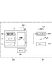
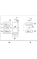
- the configuration of the control module 100 will be described with reference to FIG.
- the control module 100 includes a receiving unit 110, an input unit 120, a control unit 130, drivers 141 and 142, and a HUB 143.
- the receiving unit 110 is a part that receives control signals for controlling the operation of various devices from the engine ECU 200 and the air conditioning ECU 300.
- the control signal is a signal for controlling operations of the refrigerant control device, the cooling water control device, and the air control device described so far.
- control signals are transmitted from two ECUs including the engine ECU 200 and the air conditioning ECU 300, and the control signals are received by the receiving unit 110.
- a mode in which a control signal from a single ECU is received by the receiving unit 110 may be employed.
- a control signal for controlling the operation of the shutter actuator 22 and a control signal for controlling the operation of the hot water valve 32 are transmitted from the engine ECU 200 and received by the receiving unit 110. Further, a control signal for controlling the operation of the electric expansion valve 730 is transmitted from the air conditioning ECU 300 and received by the receiving unit 110. That is, a control signal for controlling operations of a plurality of devices is received by the receiving unit 110. Instead of such an aspect, the control signal received by the receiving unit may be for controlling the operation of a single device.
- the input unit 120 is a part to which each detection signal from the sensor 60 is input.
- the control module 100 performs control (hereinafter also referred to as “linkage control”) that links the operations of a plurality of devices included in the refrigerant control device, the cooling water control device, and the air control device. It is configured.
- the detection signal input to the input unit 120 includes a detection signal from a sensor necessary for performing the interlock control.
- a detection signal from a sensor necessary for performing the interlock control is directly input to the control module 100 from each sensor without passing through another ECU (electronic control unit). Since there is no time lag due to communication, the control module 100 can instantly grasp the measurement values of various sensors.
- the control unit 130 is a part that controls operations of various devices included in the refrigerant control device, the cooling water control device, and the air control device via a driver 141 described later.
- Control signals received from engine ECU 200 and air conditioning ECU 300 are input from receiving unit 110 to control unit 130.
- Various detection signals input from the sensor 60 are input from the input unit 120 to the control unit 130.
- the control unit 130 performs interlocking control, which will be described later, based on the input control signal and detection signal.
- the driver 141 is a part for supplying a drive current to the hot water valve 32.
- the driver 141 is supplied with power from the power supply system PL1 as power for operation.
- the driver 141 is provided with a switching element (not shown).
- the driver 141 is formed with a circuit for supplying a drive current from the power supply system PL1 to the hot water valve 32, and switching of the circuit is switched by a switching element.
- the switching element is closed by a signal from the control unit 130, the hot water valve 32 is operated and closed, and the supply of cooling water to the radiator 31 is stopped.
- the switching element is opened by a signal from the control unit 130, the hot water valve 32 is opened, and supply of cooling water to the radiator 31 is started.
- the driver 142 is a part for supplying a driving current to the electric actuator 730M of the electric expansion valve 730.
- the driver 142 is supplied with power from the power supply system PL1 as power for operation.
- the driver 142 is formed with a circuit for adjusting the magnitude of the drive current supplied to the electric actuator 730M.
- the magnitude of the driving current supplied to the electric actuator 730M is adjusted by a signal from the control unit 130.
- HUB 143 is a so-called concentrator.
- the HUB 143 is connected to signal lines connected to some of the various devices included in the refrigerant control device, the cooling water control device, and the air control device.
- a signal line connected to the shutter actuator 22 is connected to the HUB 143.
- the HUB 143 is supplied with power from the power supply system PL1 as power for operation.
- the control unit 130 is configured to control the operation of the shutter actuator 22 by transmitting only a control signal (not a driving current) to the shutter actuator 22.
- the shutter actuator 22 incorporates a driver (not shown) for controlling its operation.
- the driver operates based on a control signal transmitted from the control unit 130 via the HUB 143 and adjusts the opening degree of the shutter 21.
- the number of devices connected to the HUB 143 may be one as in this embodiment, or may be two or more.
- the HUB 143 is not provided, and all of the various devices included in the refrigerant control device, the cooling water control device, and the air control device are connected to the control unit 130 via the driver as in the hot water valve 32 in the present embodiment. It may be an aspect connected to Such a configuration is preferable when the time lag of communication between the control unit 130 and various devices becomes a problem.
- the various devices included in the refrigerant control device, the cooling water control device, and the air control device are connected to the control unit 130 via the HUB 143 like the shutter actuator 22 in the present embodiment. It may be a mode. In view of the expandability of the control module 100 and the heat exchange unit 10, such a configuration is preferable.
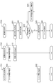
- FIG. 7 shows three flowcharts FC1, FC2, and FC3.
- a flowchart FC1 shown on the left side shows the flow of processing performed by the engine ECU 200.
- the engine ECU 200 performs a plurality of processes in parallel with the process shown in the flowchart FC1, but the illustration of the process is omitted.
- the flowchart FC2 shown in the middle shows the flow of processing performed by the air conditioning ECU 300.
- a plurality of processes are performed in parallel with the process shown in the flowchart FC2, but the illustration of the processes is omitted.
- the flowchart FC3 shown on the right side shows the flow of processing performed by the control unit 130.
- a plurality of processes for example, a process for adjusting the opening degree of the hot water valve 32
- the illustration is omitted.
- the target value for the opening degree of the shutter 21 is calculated by the engine ECU 200.
- the target value is calculated based on, for example, the operating state of the engine 51, the temperature of the cooling water circulating between the engine 51 and the radiator 31, and the like.
- step S02 following step S01 the target value of the opening degree of the shutter 21 calculated in step S01 is transmitted from the engine ECU 200 to the control module 100 as a control signal.
- a target value for the opening degree of the electric expansion valve 730 is calculated by the air conditioning ECU 300.
- the target value is calculated based on, for example, the surface temperature of the outdoor heat exchanger 740, the set temperature of the conditioned air, or the like.
- step S12 the target value of the opening of the electric expansion valve 730 calculated in step S11 is transmitted as a control signal from the air conditioning ECU 300 to the control module 100.
- step S21 the target value of the opening degree of the electric expansion valve 730 transmitted in step S12 is received by the receiving unit 110.
- step S22 following step S21 control of the electric actuator 730M is started so that the opening degree of the electric expansion valve 730 matches the target value. As described above, the control is performed by the control unit 130 transmitting a control signal to the driver 142.
- step S23 it is determined whether or not the target value of the opening degree of the electric expansion valve 730 received in step S21 has been changed from the target value received in the previous control cycle.
- step S25 the target value of the opening degree of the shutter 21 transmitted in step S02 is received by the receiving unit 110. Thereafter, in step S26 following step S25, control of the shutter actuator 22 is started so that the opening degree of the shutter 21 matches the target value. As already described, the control is performed by the control unit 130 transmitting a control signal via the HUB 144.
- step S23 When the process proceeds from step S23 to step S25 and step S26 without passing through step S24 as described above, the state of the refrigerant circulating in the refrigerant flow path 710 is in an equilibrium state, and is relatively stable. It has become.
- the opening degree of the electric expansion valve 730 is made to coincide with the opening degree calculated by the air conditioning ECU 300. Further, the opening degree of the shutter 21 is in a state that matches the opening degree calculated by the engine ECU 200.
- step S23 when the target value of the opening degree of the electric expansion valve 730 has been changed, the process proceeds to step S24.
- the transition to step S24 means that the state of the refrigerant circulating in the refrigerant flow path 710 has begun to deviate from the equilibrium state.
- the target value of the opening of the shutter 21 calculated by the engine ECU 200 that is, the target value of the opening determined in consideration of only the state of the engine 51 is appropriate for the vehicle air conditioner 70. There may be no opening.
- step S24 a correction amount for the opening degree of the shutter 21 is calculated.
- the relationship between the opening of the electric expansion valve 730 and the correction amount for the opening of the shutter 21 is stored in advance as a map.
- the correction amount for the opening degree of the shutter 21 is calculated by referring to the map.
- the calculation of the correction amount in step S24 may be performed based on a signal from the sensor 60.
- the correction amount may be calculated based on a signal from a sensor for measuring the actual opening of the shutter 21, a signal from an outside air temperature sensor, a signal from a vehicle speed sensor, or the like.
- step S24 the process proceeds to step S25.
- step S26 the opening of the shutter 21 is corrected to the target value (that is, the target value received in step S25).
- the control of the shutter actuator 22 is started so as to coincide with the value obtained by adding the correction value calculated in step S24).
- the correction amount is calculated so that the opening degree of the shutter 21 becomes larger as the opening degree of the electric expansion valve 730 adjusted based on the control signal becomes smaller.
- the correction amount is calculated so that the opening degree of the shutter 21 becomes smaller as the opening degree of the electric expansion valve 730 becomes larger.
- the opening degree of the shutter 21 is adjusted according to the opening degree of the electric expansion valve 730.
- the opening degree of the electric expansion valve 730 When the opening degree of the electric expansion valve 730 is reduced and the heat absorption amount in the outdoor heat exchanger 740 is increased, the opening degree of the shutter 21 is increased, so that the flow rate of air passing through the shutter 21 is increased. Conversely, when the opening degree of the electric expansion valve 730 increases and the heat absorption amount in the outdoor heat exchanger 740 decreases, the opening degree of the shutter 21 decreases, so that the flow rate of air passing through the shutter 21 is reduced. Get smaller.
- control for interlocking the operation of the outdoor heat exchanger 740 and the operation of the shutter 21, that is, interlock control is executed.
- interlock control since the opening degree of the shutter 21 is corrected as necessary, the flow of air and refrigerant in the heat exchange unit 10 can be adjusted more appropriately.
- the control unit 130 may correct the operation of the shutter 21 indicated by the control signal as described above. However, all the operations of the shutter 21 are performed.
- the control unit 130 may be determined independently of the control signal from the host ECU. For example, even when a control signal for operating the shutter 21 is not transmitted from the engine ECU 200, the control unit 130 may perform a process for operating the shutter 21 as necessary. .
- the operation of the outdoor heat exchanger 740 and the operation of the shutter 21 are both controlled by the control unit 130, the operation timing of each device is not shifted due to the communication delay between the ECUs. More appropriate control can be realized.
- the first process (step S22) for controlling the operation of the outdoor heat exchanger 740 in the interlock control and the second process (step S26) for controlling the operation of the shutter actuator 22 are performed in this embodiment. Then, it is executed within a period included in a single control cycle. For this reason, the first process and the second process can be executed at substantially the same timing.
- the execution timing of the first process and the execution timing of the second process can be shifted.
- the process of step S26 may be started after a predetermined number of times have passed since the process of step S22 was first executed.
- the process of step S ⁇ b> 26 may be skipped until the predetermined number of control cycles elapses.
- each of the first process and the second process can be executed at an appropriate timing.
- refrigerant control included in the heat exchange system 10 is used as the apparatus (first apparatus) whose operation is controlled in the first process and the apparatus (second apparatus) whose operation is controlled in the second process.
- Arbitrary devices can be selected from each of the device, the cooling water control device, and the air control device. Thereby, each process for operating a plurality of devices in the interlock control may be executed within a period included in a single control cycle.
- the control module 100 grasps the three fluid states relatively accurately in the heat exchange unit 10 as compared with the engine ECU 200 that considers only the operation of the engine 51 and the air conditioning ECU 300 that considers only the operation of the vehicle air conditioner 70. Is something that can be done. Since the control unit 130 of such a control module 100 performs interlocking control in place of the air conditioning ECU 300 and the like, the flow of various fluids can be adjusted more appropriately.
- the above interlock control is performed so that the operation of the electric expansion valve 730, which is one of the refrigerant control devices, and the operation of the shutter actuator 22, which is one of the air control devices, are interlocked.
- the combination of a plurality of devices to be subjected to the interlock control described above is merely an example, and may be arbitrarily set so as to be a combination different from the above.
- interlocking control that interlocks three or more devices may be performed.
- the interlock control may be performed so that the operation of the hot water valve 32 that is one of the cooling water control devices and the operation of the shutter 21 that is one of the air control devices are interlocked.
- the engine 51 can be warmed up more quickly by switching the hot water valve 32 to the closed state when the shutter 21 is closed.
- the interlock control may be performed so that the operation of the electric expansion valve 730, which is one of the refrigerant control devices, and the operation of the hot water valve 32, which is one of the cooling water control devices, are interlocked.
- the opening degree of the electric expansion valve 730 is increased and the hot water valve 32 is opened, thereby quickly using the heat of the cooling water. Defrosting can be performed. In this case, even if a control signal for opening the hot water valve 32 is not transmitted from the engine ECU 200, the control unit 130 performs control for opening the hot water valve 32.
- control module 100 is disposed in the engine room ER, and is configured to perform these controls at a position close to the electric expansion valve 730, the shutter actuator 22, and the like. For this reason, the number of harnesses routed from the vehicle interior IR toward the electric expansion valve 730 and the like can be reduced as compared with a configuration in which the engine ECU 200 and the air conditioning ECU 300 directly control the electric expansion valve 730 and the like. .
- the control module 100 is configured on the circuit board BD1 of the electric expansion valve 730, and is configured integrally with the electric expansion valve 730. Therefore, the operation control of the electric expansion valve 730, which is one of the refrigerant control devices, can be quickly started immediately after receiving the control signal from the air conditioning ECU 300.
- the control module 100 may be configured integrally with another device different from the electric expansion valve 730 among the refrigerant control device, the cooling water control device, and the air control device.
- the device in which the control module 100 is integrated is preferably one of a plurality of devices that operate in conjunction with each other in the interlock control.
- all power necessary for performing interlock control is supplied to the control module 100 from the power supply system PL1 that can supply power even when the engine 51 of the vehicle 50 is stopped.
- the drivers 141 and 142 and the HUB 143 are distributed. For this reason, interlocking control can be performed even when the engine 51 is stopped.
- the electric fan 40 is provided with a circuit board BD ⁇ b> 2 for operating the fan motor 42.
- the components of the control module 100A according to the present embodiment are also arranged. That is, the control module 100A is configured integrally with the electric fan 40 that is an air control device.
- the control module 100A and the electric expansion valve 730 are connected by a communication line (not shown).
- the illustration of the rotor blade 41 included in the electric fan 40 is omitted.
- the heat exchange unit 10A including the control module 100A and the surrounding configuration are as shown in FIG.
- the operation of the electric fan 40 that is one of the air control devices the operation of the hot water valve 32 that is one of the cooling water control devices, and the operation of the electric expansion valve 730 that is one of the refrigerant control devices.
- the control module 100A the operation of the electric fan 40 that is one of the air control devices, the operation of the hot water valve 32 that is one of the cooling water control devices, and the operation of the electric expansion valve 730 that is one of the refrigerant control devices.
- the control module 100A includes drivers 141 and 144 and a HUB 145.
- the hot water valve 32 is connected to the driver 141 as in the first embodiment.
- the driver 144 is a part for supplying a driving current to the fan motor 42 of the electric fan 40.
- the driver 144 is supplied with power from the power supply system PL1 as power for operation.
- the driver 144 is formed with a circuit for adjusting the magnitude of the driving current supplied to the fan motor 42.
- the magnitude of the drive current supplied to the fan motor 42 is adjusted by a signal from the control unit 130.
- the HUB 145 is a concentrator similar to the HUB 143 of the first embodiment.
- the HUB 145 is connected to signal lines connected to some of the various devices included in the refrigerant control device, the cooling water control device, and the air control device.
- a signal line connected to the electric actuator 730M of the electric expansion valve 730 is connected to the HUB 145.
- the HUB 145 is supplied with power from the power supply system PL1 as power for operation.
- interlock control is performed so that the operation of the electric fan 40 that is one of the air control devices and the operation of the electric expansion valve 730 that is one of the refrigerant control devices are interlocked.
- all power necessary for performing interlock control is supplied to the control module 100 from the power supply system PL1 that can supply power even when the engine 51 of the vehicle 50 is stopped.
- the electric power is distributed to the drivers 141 and 142 and the HUB 145. For this reason, interlocking control can be performed even when the engine 51 is stopped.
- interlocking control is performed such that the rotational speed of the electric fan 40 is changed according to the opening degree of the electric expansion valve 730. Can do. Thereby, the power consumption in the electric fan 40 can be suppressed as compared with the control in which the rotation speed of the electric fan 40 is always constant.
Landscapes
- Engineering & Computer Science (AREA)
- Mechanical Engineering (AREA)
- Physics & Mathematics (AREA)
- Thermal Sciences (AREA)
- Chemical & Material Sciences (AREA)
- Combustion & Propulsion (AREA)
- Transportation (AREA)
- General Engineering & Computer Science (AREA)
- Air-Conditioning For Vehicles (AREA)
- Cooling, Air Intake And Gas Exhaust, And Fuel Tank Arrangements In Propulsion Units (AREA)
Priority Applications (1)
| Application Number | Priority Date | Filing Date | Title |
|---|---|---|---|
| DE112017005736.1T DE112017005736T5 (de) | 2016-11-15 | 2017-10-02 | Steuerungsmodul |
Applications Claiming Priority (2)
| Application Number | Priority Date | Filing Date | Title |
|---|---|---|---|
| JP2016-222174 | 2016-11-15 | ||
| JP2016222174A JP6583217B2 (ja) | 2016-11-15 | 2016-11-15 | 制御モジュール |
Publications (1)
| Publication Number | Publication Date |
|---|---|
| WO2018092438A1 true WO2018092438A1 (ja) | 2018-05-24 |
Family
ID=62145217
Family Applications (1)
| Application Number | Title | Priority Date | Filing Date |
|---|---|---|---|
| PCT/JP2017/035801 WO2018092438A1 (ja) | 2016-11-15 | 2017-10-02 | 制御モジュール |
Country Status (3)
| Country | Link |
|---|---|
| JP (1) | JP6583217B2 (de) |
| DE (1) | DE112017005736T5 (de) |
| WO (1) | WO2018092438A1 (de) |
Families Citing this family (2)
| Publication number | Priority date | Publication date | Assignee | Title |
|---|---|---|---|---|
| JP7206670B2 (ja) * | 2018-07-25 | 2023-01-18 | 株式会社デンソー | 熱交換器 |
| JP2021042878A (ja) * | 2019-09-06 | 2021-03-18 | 東芝キヤリア株式会社 | 冷凍サイクル装置 |
Citations (6)
| Publication number | Priority date | Publication date | Assignee | Title |
|---|---|---|---|---|
| JP2003170733A (ja) * | 2001-12-05 | 2003-06-17 | Honda Motor Co Ltd | 自動車用空調装置 |
| JP2004268778A (ja) * | 2003-03-10 | 2004-09-30 | Calsonic Kansei Corp | エアコン制御装置 |
| JP2011068155A (ja) * | 2009-09-22 | 2011-04-07 | Denso Corp | 車両用空調装置 |
| JP2014006020A (ja) * | 2012-06-26 | 2014-01-16 | Fuji Koki Corp | 電動弁制御装置及び電動弁装置 |
| JP2014118120A (ja) * | 2012-12-19 | 2014-06-30 | T Rad Co Ltd | 電気自動車の熱交換装置 |
| JP2014223867A (ja) * | 2013-05-16 | 2014-12-04 | カルソニックカンセイ株式会社 | 車両用空調装置 |
Family Cites Families (4)
| Publication number | Priority date | Publication date | Assignee | Title |
|---|---|---|---|---|
| JP2002120546A (ja) * | 2000-10-16 | 2002-04-23 | Denso Corp | 車両用空調装置 |
| JP2008221997A (ja) * | 2007-03-12 | 2008-09-25 | Toyota Motor Corp | 車両用空調装置 |
| JP2008302721A (ja) | 2007-06-05 | 2008-12-18 | Calsonic Kansei Corp | 車両用空調制御装置 |
| JP2016222174A (ja) | 2015-06-02 | 2016-12-28 | 株式会社豊田中央研究所 | 摩擦ブレーキの制御装置 |
-
2016
- 2016-11-15 JP JP2016222174A patent/JP6583217B2/ja active Active
-
2017
- 2017-10-02 DE DE112017005736.1T patent/DE112017005736T5/de not_active Withdrawn
- 2017-10-02 WO PCT/JP2017/035801 patent/WO2018092438A1/ja active Application Filing
Patent Citations (6)
| Publication number | Priority date | Publication date | Assignee | Title |
|---|---|---|---|---|
| JP2003170733A (ja) * | 2001-12-05 | 2003-06-17 | Honda Motor Co Ltd | 自動車用空調装置 |
| JP2004268778A (ja) * | 2003-03-10 | 2004-09-30 | Calsonic Kansei Corp | エアコン制御装置 |
| JP2011068155A (ja) * | 2009-09-22 | 2011-04-07 | Denso Corp | 車両用空調装置 |
| JP2014006020A (ja) * | 2012-06-26 | 2014-01-16 | Fuji Koki Corp | 電動弁制御装置及び電動弁装置 |
| JP2014118120A (ja) * | 2012-12-19 | 2014-06-30 | T Rad Co Ltd | 電気自動車の熱交換装置 |
| JP2014223867A (ja) * | 2013-05-16 | 2014-12-04 | カルソニックカンセイ株式会社 | 車両用空調装置 |
Also Published As
| Publication number | Publication date |
|---|---|
| JP2018079756A (ja) | 2018-05-24 |
| JP6583217B2 (ja) | 2019-10-02 |
| DE112017005736T5 (de) | 2019-08-14 |
Similar Documents
| Publication | Publication Date | Title |
|---|---|---|
| EP4122726A1 (de) | Wärmepumpensystem für ein fahrzeug | |
| JP5611072B2 (ja) | ヒートポンプ式車両用空調装置およびその除霜方法 | |
| JP6108322B2 (ja) | 車両用空調装置 | |
| WO2013175863A1 (ja) | 車両用ヒートポンプ空調システム | |
| WO2014087645A1 (ja) | 車両用ヒートポンプ装置および車両用空調装置 | |
| US20160001635A1 (en) | Vehicular air conditioning device, and component unit thereof | |
| JP2008308080A (ja) | 自動車の吸放熱システムおよびその制御方法 | |
| US10611212B2 (en) | Air conditioner for vehicle | |
| JP7115452B2 (ja) | 冷却システム | |
| JP7111082B2 (ja) | 冷却システム | |
| WO2018123289A1 (ja) | 制御モジュール | |
| WO2015072126A1 (ja) | 車両用空調装置およびその構成ユニット | |
| EP3878670A1 (de) | Fahrzeugtemperaturregelsystem | |
| US11260724B2 (en) | Vehicular air conditioning system and method for controlling the same | |
| CN114144321A (zh) | 用于车辆的热管理装置以及用于车辆的热管理方法 | |
| WO2018092438A1 (ja) | 制御モジュール | |
| JP2017171247A (ja) | 車両用空調装置 | |
| JP6103186B2 (ja) | 車両用ヒートポンプ装置および車両用空調装置 | |
| JP6232592B2 (ja) | 車両用ヒートポンプ装置および車両用空調装置 | |
| CN117136144A (zh) | 车辆用空气调节系统以及车辆用空气调节方法 | |
| JP6031676B2 (ja) | 車両用ヒートポンプ装置および車両用空調装置 | |
| US20070271943A1 (en) | Air-Conditioning System Provided With a Heat Pump | |
| EP1500536A1 (de) | Kühlungsvorrichtung und Steuerungsverfahren eines Kraftfahrzeugkühlungsgebläses | |
| JP2014113837A (ja) | 車両用空調装置 | |
| WO2021049339A1 (ja) | 熱交換モジュール |
Legal Events
| Date | Code | Title | Description |
|---|---|---|---|
| 121 | Ep: the epo has been informed by wipo that ep was designated in this application |
Ref document number: 17871367 Country of ref document: EP Kind code of ref document: A1 |
|
| 122 | Ep: pct application non-entry in european phase |
Ref document number: 17871367 Country of ref document: EP Kind code of ref document: A1 |