WO2018092243A1 - 作業位置補正方法および作業ロボット - Google Patents
作業位置補正方法および作業ロボット Download PDFInfo
- Publication number
- WO2018092243A1 WO2018092243A1 PCT/JP2016/084121 JP2016084121W WO2018092243A1 WO 2018092243 A1 WO2018092243 A1 WO 2018092243A1 JP 2016084121 W JP2016084121 W JP 2016084121W WO 2018092243 A1 WO2018092243 A1 WO 2018092243A1
- Authority
- WO
- WIPO (PCT)
- Prior art keywords
- work
- robot
- correction
- correction method
- matrix
- Prior art date
Links
Images


Classifications
-
- B—PERFORMING OPERATIONS; TRANSPORTING
- B25—HAND TOOLS; PORTABLE POWER-DRIVEN TOOLS; MANIPULATORS
- B25J—MANIPULATORS; CHAMBERS PROVIDED WITH MANIPULATION DEVICES
- B25J9/00—Programme-controlled manipulators
- B25J9/16—Programme controls
- B25J9/1679—Programme controls characterised by the tasks executed
- B25J9/1692—Calibration of manipulator
-
- B—PERFORMING OPERATIONS; TRANSPORTING
- B25—HAND TOOLS; PORTABLE POWER-DRIVEN TOOLS; MANIPULATORS
- B25J—MANIPULATORS; CHAMBERS PROVIDED WITH MANIPULATION DEVICES
- B25J13/00—Controls for manipulators
- B25J13/08—Controls for manipulators by means of sensing devices, e.g. viewing or touching devices
-
- B—PERFORMING OPERATIONS; TRANSPORTING
- B25—HAND TOOLS; PORTABLE POWER-DRIVEN TOOLS; MANIPULATORS
- B25J—MANIPULATORS; CHAMBERS PROVIDED WITH MANIPULATION DEVICES
- B25J19/00—Accessories fitted to manipulators, e.g. for monitoring, for viewing; Safety devices combined with or specially adapted for use in connection with manipulators
- B25J19/02—Sensing devices
- B25J19/021—Optical sensing devices
- B25J19/023—Optical sensing devices including video camera means
-
- B—PERFORMING OPERATIONS; TRANSPORTING
- B25—HAND TOOLS; PORTABLE POWER-DRIVEN TOOLS; MANIPULATORS
- B25J—MANIPULATORS; CHAMBERS PROVIDED WITH MANIPULATION DEVICES
- B25J9/00—Programme-controlled manipulators
- B25J9/10—Programme-controlled manipulators characterised by positioning means for manipulator elements
-
- B—PERFORMING OPERATIONS; TRANSPORTING
- B25—HAND TOOLS; PORTABLE POWER-DRIVEN TOOLS; MANIPULATORS
- B25J—MANIPULATORS; CHAMBERS PROVIDED WITH MANIPULATION DEVICES
- B25J9/00—Programme-controlled manipulators
- B25J9/16—Programme controls
- B25J9/1628—Programme controls characterised by the control loop
- B25J9/1638—Programme controls characterised by the control loop compensation for arm bending/inertia, pay load weight/inertia
-
- B—PERFORMING OPERATIONS; TRANSPORTING
- B25—HAND TOOLS; PORTABLE POWER-DRIVEN TOOLS; MANIPULATORS
- B25J—MANIPULATORS; CHAMBERS PROVIDED WITH MANIPULATION DEVICES
- B25J9/00—Programme-controlled manipulators
- B25J9/16—Programme controls
- B25J9/1656—Programme controls characterised by programming, planning systems for manipulators
- B25J9/1664—Programme controls characterised by programming, planning systems for manipulators characterised by motion, path, trajectory planning
-
- B—PERFORMING OPERATIONS; TRANSPORTING
- B25—HAND TOOLS; PORTABLE POWER-DRIVEN TOOLS; MANIPULATORS
- B25J—MANIPULATORS; CHAMBERS PROVIDED WITH MANIPULATION DEVICES
- B25J9/00—Programme-controlled manipulators
- B25J9/16—Programme controls
- B25J9/1694—Programme controls characterised by use of sensors other than normal servo-feedback from position, speed or acceleration sensors, perception control, multi-sensor controlled systems, sensor fusion
- B25J9/1697—Vision controlled systems
-
- H—ELECTRICITY
- H05—ELECTRIC TECHNIQUES NOT OTHERWISE PROVIDED FOR
- H05K—PRINTED CIRCUITS; CASINGS OR CONSTRUCTIONAL DETAILS OF ELECTRIC APPARATUS; MANUFACTURE OF ASSEMBLAGES OF ELECTRICAL COMPONENTS
- H05K13/00—Apparatus or processes specially adapted for manufacturing or adjusting assemblages of electric components
- H05K13/08—Monitoring manufacture of assemblages
- H05K13/089—Calibration, teaching or correction of mechanical systems, e.g. of the mounting head
-
- B—PERFORMING OPERATIONS; TRANSPORTING
- B25—HAND TOOLS; PORTABLE POWER-DRIVEN TOOLS; MANIPULATORS
- B25J—MANIPULATORS; CHAMBERS PROVIDED WITH MANIPULATION DEVICES
- B25J9/00—Programme-controlled manipulators
- B25J9/16—Programme controls
- B25J9/1628—Programme controls characterised by the control loop
- B25J9/1653—Programme controls characterised by the control loop parameters identification, estimation, stiffness, accuracy, error analysis
-
- G—PHYSICS
- G05—CONTROLLING; REGULATING
- G05B—CONTROL OR REGULATING SYSTEMS IN GENERAL; FUNCTIONAL ELEMENTS OF SUCH SYSTEMS; MONITORING OR TESTING ARRANGEMENTS FOR SUCH SYSTEMS OR ELEMENTS
- G05B2219/00—Program-control systems
- G05B2219/30—Nc systems
- G05B2219/45—Nc applications
- G05B2219/45063—Pick and place manipulator
Definitions
- This specification discloses a work position correction method and a work robot.
- a robot that controls the operation of the robot by applying coordinate transformation by applying a DH parameter to a target point has been proposed (for example, see Patent Document 1).
- Setting of the DH parameter is performed as follows. That is, the robot control device sets measurement points in the robot operation space. Next, the control device moves the robot to the measurement point and acquires three-dimensional position data. Then, the control device derives a DH parameter from the error between the acquired position data and the measurement point. When controlling the operation of the robot based on the target point, the control device performs coordinate conversion by applying the DH parameter to the target point.
- the work robot described above may not be able to ensure sufficient work accuracy even if the DH parameters used for coordinate transformation are optimized. For example, if an error (for example, arm distortion) that cannot be corrected by optimization of the DH parameter is included, the work robot cannot move to an accurate position due to the influence of the error.
- an error for example, arm distortion
- the main purpose of this disclosure is to ensure the work accuracy required when operating the work robot by specifying the target position.
- the work position correction method of the present disclosure is a work position correction method when operating an articulated work robot by designating a target position, and sets a plurality of work points in a movable region of the work robot,
- the gist is to set a correction parameter in which a spatial coordinate value and a correction value are associated with each other for the plurality of set work points, and reflect the set correction parameter on the target position.
- this work position correction method of the present disclosure first, a plurality of work points are set within the movable area of the work robot. Next, in the work position correction method, a correction parameter in which a spatial coordinate value is associated with a correction value is set for a plurality of set work points. In the work position correction method, the set correction parameter is reflected on the target position. Thereby, even if an error is included in the robot arm, the work robot can be more accurately moved to the target position without being affected by the error. As a result, according to the present disclosure, it is possible to ensure sufficient work accuracy when operating the work robot by designating the target position.
- the work robot includes a multi-joint type robot arm, an actuator that drives each joint of the robot arm, and a plurality of work coordinate lines arranged in a matrix within the movable area of the robot arm. And a correction device stored in the storage device, the target position is corrected using the correction parameter stored in the storage device, and the actuator is controlled based on the corrected target position. And a control device.
- the work robot includes a robot arm, an actuator, a storage device, and a control device.
- the storage device stores a correction parameter in which a spatial coordinate value and a correction value are associated with each other for a plurality of work points arranged in a matrix within the movable region of the robot arm.
- the control device corrects the target position using the correction parameter stored in the storage device, and controls the actuator based on the corrected target position.
- FIG. 1 is a configuration diagram showing an outline of a configuration of a robot system 10.
- FIG. 2 is a configuration diagram showing an outline of the configuration of a robot 20.
- FIG. 3 is a block diagram showing an electrical connection relationship between a robot 20 and a control device 70.
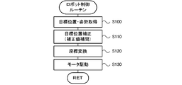
- FIG. It is a flowchart which shows an example of a robot control routine.
- It is explanatory drawing which shows an example of a matrix correction parameter.
- FIG. 1 is a configuration diagram showing an outline of the configuration of the robot system 10.
- FIG. 2 is a configuration diagram showing an outline of the configuration of the robot 20.
- FIG. 3 is a block diagram showing an electrical connection relationship between the robot 20 and the control device 70. 1 and 2, the front-rear direction is the X-axis direction, the left-right direction is the Y-axis direction, and the up-down direction is the Z-axis direction.
- the robot system 10 includes a robot 20 and a control device 70 that controls the robot 20.
- the robot system 10 is configured as a system that picks up a work and places the picked-up work on an object.
- the robot system 10 is configured as a component mounting system that collects components and mounts them on the substrate S.
- the robot system is not limited to the system described above, and can be applied to any system as long as it is a system that performs work on a workpiece using the robot 20.
- the robot 20 includes a 5-axis vertical articulated arm (hereinafter referred to as an arm) 22 and an end effector (not shown) which is a hand of the robot 20.
- the arm 22 includes six links (first to sixth links 31 to 36) and five joints (first to fifth joints 41 to 45) that connect the links so as to be rotatable or pivotable.
- Each joint (first to fifth joints 41 to 45) includes a motor (first to fifth motors 51 to 55) for driving the corresponding joint, and an encoder (first to fifth) for detecting the rotation angle of the corresponding motor.
- Encoders 61 to 65 the motor is a servo motor and the encoder is a rotary encoder.
- the end effector is attached to the distal end link (sixth link 36) of the arm 22, and can hold and release the part (workpiece).
- the end effector for example, a mechanical chuck, a suction nozzle, an electromagnet, or the like can be used.
- a mark camera 24 is attached to the arm 22 (fifth link 35) for imaging the mark M attached to an object such as a work object installed on the work table 11.
- the proximal end link (first link 31) of the arm 22 is fixed to the work table 11.
- a substrate transfer device 12 On the work table 11, a substrate transfer device 12, a component supply device 13, a parts camera 14, and the like are arranged.
- the substrate transport apparatus 12 includes a pair of belt conveyors that are stretched in the left-right direction (X-axis direction) with a space in the front-rear direction (Y-axis direction).
- substrate S is conveyed from the left to the right by the belt conveyor.
- the component supply device 13 is configured as a tape feeder that feeds a tape in which a plurality of components are accommodated at predetermined intervals to the rear (Y-axis direction).
- the component supply device 13 is not limited to a tape feeder, and may be any type of component supply device such as a tray feeder that supplies a tray on which a plurality of components are arranged.
- the part camera 14 captures an image of the component held by the end effector when the component passes above the part camera 14, and outputs the captured image to the control device 70.
- the control device 70 is configured as a microprocessor centered on the CPU 71, and includes a ROM 72, an HDD 73, a RAM 74, a drive circuit 75, and the like in addition to the CPU 71.
- the drive circuit 75 is a circuit for driving the first to fifth motors 51 to 55. Signals are input to the control device 70 from the first to fifth encoders 61 to 65, the parts camera 14, the mark camera 24, the input device 76, and the like. Signals are output from the control device 70 to the substrate transfer device 12, the component supply device 13, the output device 77, and the first to fifth motors 51 to 55.
- the input device 76 is an input device on which an operator performs an input operation.
- the output device 77 is a display device for displaying various information.
- FIG. 4 is a flowchart showing an example of a robot control routine executed by the control device 70. This routine is repeatedly executed every predetermined time.
- the CPU 71 of the control device 70 first acquires the target position and orientation (S100).
- the target position and posture are the position and posture of the end effector when picking up a component when the picking operation is performed.
- the target position and orientation are the position and orientation of the end effector when the collected component is mounted on the board S when the mounting operation is executed.
- FIG. 5 is an explanatory diagram showing an example of matrix correction parameters.
- the matrix correction parameter is obtained by associating work point identification information (work point No.), a spatial coordinate value, and a correction value (three-dimensional offset amount), and is stored in the HDD 73. Yes.
- the target position is corrected by deriving a correction value at the target position from the correction values of a plurality of work points around the target position using a known interpolation method such as linear interpolation, and offsetting the target position by the derived correction value. Can be done.
- the correction of the target position may be performed by offsetting the target position with the correction value of the work point closest to the target position.
- the CPU 71 sets the target angle of each joint (first to fifth joints 41 to 45) by converting the coordinates of the corrected target position and posture (S120).
- the coordinate conversion can be performed using, for example, a well-known DH parameter.
- the CPU 71 drives and controls the corresponding motor (first motors 51 to 55) based on the set target angle (S130), and ends the robot control routine.
- the CPU 71 causes the end effector to hold the component so that the component is sampled when the end effector reaches the target position and posture.
- the CPU 71 causes the end effector to release the holding of the component so that the component is mounted on the substrate S when the end effector reaches the target position and posture.
- FIG. 6 is an explanatory diagram illustrating an example of a work position correction process.
- the work position correction step is performed by executing assembly adjustment (S200), geometry adjustment (S210), calibration (S220), and matrix measurement / correction (S230) in this order.
- assembly adjustment S200
- geometry adjustment S210
- calibration S220
- matrix measurement / correction S230
- the order of explanation is matrix measurement / correction, assembly adjustment, geometry adjustment, and calibration.
- Matrix measurement / correction is a process for setting the matrix correction parameter used for correcting the target position described above.
- FIG. 7 is an explanatory diagram showing an example of matrix measurement / correction.
- the matrix measurement corresponds to S300 to S330 in FIG.
- the matrix correction includes S340 and S350 in FIG. 7 and S110 in FIG.
- FIG. 8 is an explanatory diagram showing a state in which the three-dimensional measurement is performed on the marker m using the three-dimensional measuring instrument 100.
- an area A is a work area for the robot 20.
- the operator attaches a measurement marker m to the distal link and installs the three-dimensional measuring instrument 100 at the corner of the work table 11 as shown in FIG.
- the three-dimensional measuring instrument 100 can use a laser tracker or a motion capture.
- the CPU 71 of the control device 70 first sets a plurality of work points in a matrix at a designated pitch in the work area A of the robot 20 (S300).
- FIG. 9 is an explanatory diagram illustrating an example of work points.
- the pitch is designated by operating the input device 76 by the operator.
- the CPU 71 designates the spatial coordinate value of each work point as a target position, and controls the arm 22 (first to fifth motors 51 to 55) so as to move to the target position designated by the marker m (S310). .
- the control device 70 inputs the actual position of the marker m measured by the three-dimensional measuring instrument 100 (S320).
- the CPU 71 derives a difference between the spatial coordinate value and the input actual position of the marker m for each work point (S330).
- the CPU 71 derives a correction value (offset value) from the derived difference (S340).
- the CPU 71 sets a matrix correction parameter in which the spatial coordinate value and the correction value are associated for each work point (S350), and ends the matrix measurement / correction.
- the assembly adjustment is a process of adjusting the assembly angle using a jig when assembling each link (first to sixth links 31 to 36).
- Geometry adjustment is a process of optimizing DH parameters used for coordinate transformation.
- the operator attaches the measurement marker m to the distal link and installs the three-dimensional measuring instrument 100 at the corner of the work table 11 as in the matrix measurement / correction.
- the CPU 71 sets a plurality of measurement points in the work area A of the robot 20.
- the measurement point can be set, for example, by the operator operating the input device 76 and specifying the measurement point.
- the CPU 71 designates the spatial coordinate value of each measurement point as a target position, and controls the arm 22 (first to fifth motors 51 to 55) so that the marker m moves to the designated target position.
- the CPU 71 inputs the actual position of the marker m measured by the three-dimensional measuring instrument 100, and DH so that the difference (error) between the spatial coordinate value of the measurement point and the actual position of the input marker m is minimized. Calculate the parameters and finish the geometry adjustment.
- Calibration is a process of grasping the relative positional relationship between the robot 20 and the work table 11 (work object) and reflecting it in the target position when the robot 20 is operated.
- FIG. 10 is an explanatory diagram showing the state of calibration.
- the operator fixes the object 110 with the mark M on the work table 11 at a predetermined position.
- the CPU 71 first controls the arm 22 (first to fifth motors 51 to 55) so that the mark camera 24 moves above the object 110. Subsequently, the CPU 71 images the mark M attached to the object 110 with the mark camera 24.
- the CPU 71 performs coordinate conversion of the rotation angle of each joint detected by the encoders (first to fifth encoders 61 to 65) to calculate the position (imaging position) of the mark camera 24 at the time of imaging.
- the CPU 71 recognizes the position of the mark M that appears in the captured image using the calculated imaging position as a reference.
- the CPU 71 identifies the relative positional relationship between the robot 20 and the workbench 11 from the recognized position of the mark M, reflects it in the target position when operating the robot 20, and ends the calibration.
- the matrix measurement / correction is executed after the geometry adjustment and the calibration are executed. That is, the matrix measurement / correction is performed in a state where the positional accuracy of the robot 20 is improved to some extent by performing geometry adjustment or calibration.
- the correction accuracy of the matrix correction parameter derived by the matrix measurement / correction increases as the pitch between the work points specified in the matrix measurement / correction becomes finer.
- the matrix measurement / correction takes a long time to execute.
- the matrix correction parameter increases the number of data and increases the necessary storage capacity.
- by performing geometry adjustment and calibration before matrix measurement / correction it is possible to obtain a correction value with a required accuracy over the entire work area without setting the pitch excessively finely.
- the arm 22 corresponds to a robot arm
- the motor corresponds to an actuator
- the HDD 73 corresponds to a storage device
- the control device. 70 corresponds to a control device.
- a plurality of work points are set in the movable region of the robot 20, and a matrix measurement parameter for setting a matrix correction parameter in which spatial coordinate values and correction values are associated with each other at the set work points is set.
- the control device 70 of the robot 20 corrects the designated target position using the matrix correction parameter. As a result, even when the arm 22 includes an error that cannot be corrected by geometry adjustment or calibration, the control device 70 can move the arm 22 to the target position more accurately without being affected by the error.
- geometry adjustment is performed before matrix measurement / correction.
- the robot 20 can further improve the position accuracy by a combination of geometry adjustment and matrix measurement / correction.
- by performing the geometry adjustment before the matrix measurement / correction it is possible to obtain a correction value with the required accuracy over the entire work area without excessively finely setting the pitch in the matrix measurement. it can.
- calibration is performed before matrix measurement / correction. For this reason, the robot 20 can correctly grasp the relative positional relationship with the workbench 11 and can further improve the positional accuracy.
- the robot 20 by executing calibration before matrix measurement / correction, it is possible to obtain a correction value with necessary accuracy over the entire work area without excessively finely setting the pitch in matrix measurement. it can.
- the assembly adjustment, the geometry adjustment, and the calibration are executed in addition to the matrix measurement / correction, but some or all of them may be omitted.
- the calibration is performed after the geometry adjustment. However, the calibration may be performed before the geometry adjustment.
- the CPU 71 sets a plurality of work points so as to be arranged in a matrix at a predetermined pitch in the matrix measurement.
- the CPU 71 may set a plurality of work points according to other rules.
- the robot 20 has five-axis joints. However, the robot 20 may have four-axis joints or six-axis joints. Moreover, although the robot 20 has only a rotation / turning joint, it may have a linear motion joint.
- the work position correction method of the present disclosure is a work position correction method for operating a multi-joint type work robot by designating a target position, and a plurality of work position correction methods within a movable region of the work robot.
- a work point is set, a correction parameter in which a spatial coordinate value and a correction value are associated with each other is set for the plurality of set work points, and the set correction parameter is reflected on the target position.
- the plurality of work points may be set so as to be arranged in a matrix at a predetermined pitch. According to the present disclosure, necessary work accuracy can be easily ensured by appropriately setting the pitch between adjacent work points.
- the work robot is moved at each work point by setting the plurality of work points, sequentially designating each spatial coordinate value of the set work points as a target position.
- the actual position of the work robot is measured, matrix measurement is performed to derive the difference between the spatial coordinate value of each work point and the measured actual position, and a correction value for each work point is derived based on the derived difference.
- the correction parameter may be set by associating the spatial coordinate value with the derived correction value for each work point, and matrix correction may be performed to reflect the set correction parameter on the target position. According to the work position correction method of the present disclosure, it is possible to derive a more accurate correction value for each work point.
- a correction value between adjacent work points may be interpolated. According to the work position correction method of the present disclosure, even when the target position is specified at a position shifted from the set work point, the required position accuracy can be ensured.
- geometry adjustment for adjusting a conversion parameter used for coordinate conversion of the target position may be performed before the matrix measurement.
- work precision can be further improved by a combination of matrix correction and geometry adjustment.
- the work position correction method of the present disclosure since the geometry adjustment is performed before the matrix measurement, the required position accuracy can be ensured without increasing the number of work points required for the matrix measurement. it can.
- the relative position relationship between the work robot on which a work target on which the work robot performs work and the work robot is specified is specified, and the target position is determined. It is good also as what performs the calibration reflected in.
- work precision can be further improved by a combination of matrix measurement, geometry adjustment, and calibration.
- the work position correction method of the present disclosure since the calibration is performed before the matrix measurement, the required position accuracy can be ensured without increasing the number of work points necessary for the matrix measurement. it can.
- This disclosure can be used in the manufacturing industry of work robots.
Landscapes
- Engineering & Computer Science (AREA)
- Robotics (AREA)
- Mechanical Engineering (AREA)
- Operations Research (AREA)
- Manufacturing & Machinery (AREA)
- Microelectronics & Electronic Packaging (AREA)
- Human Computer Interaction (AREA)
- Multimedia (AREA)
- Manipulator (AREA)
Priority Applications (5)
| Application Number | Priority Date | Filing Date | Title |
|---|---|---|---|
| EP16921959.9A EP3542969B1 (en) | 2016-11-17 | 2016-11-17 | Working-position correcting method and working robot |
| JP2018550941A JP6661028B2 (ja) | 2016-11-17 | 2016-11-17 | 作業位置補正方法 |
| US16/341,242 US11285609B2 (en) | 2016-11-17 | 2016-11-17 | Working position correcting method and working robot |
| CN201680090821.6A CN109996653B (zh) | 2016-11-17 | 2016-11-17 | 作业位置校正方法及作业机器人 |
| PCT/JP2016/084121 WO2018092243A1 (ja) | 2016-11-17 | 2016-11-17 | 作業位置補正方法および作業ロボット |
Applications Claiming Priority (1)
| Application Number | Priority Date | Filing Date | Title |
|---|---|---|---|
| PCT/JP2016/084121 WO2018092243A1 (ja) | 2016-11-17 | 2016-11-17 | 作業位置補正方法および作業ロボット |
Publications (1)
| Publication Number | Publication Date |
|---|---|
| WO2018092243A1 true WO2018092243A1 (ja) | 2018-05-24 |
Family
ID=62145357
Family Applications (1)
| Application Number | Title | Priority Date | Filing Date |
|---|---|---|---|
| PCT/JP2016/084121 WO2018092243A1 (ja) | 2016-11-17 | 2016-11-17 | 作業位置補正方法および作業ロボット |
Country Status (5)
| Country | Link |
|---|---|
| US (1) | US11285609B2 (zh) |
| EP (1) | EP3542969B1 (zh) |
| JP (1) | JP6661028B2 (zh) |
| CN (1) | CN109996653B (zh) |
| WO (1) | WO2018092243A1 (zh) |
Cited By (3)
| Publication number | Priority date | Publication date | Assignee | Title |
|---|---|---|---|---|
| US20200101621A1 (en) * | 2018-09-28 | 2020-04-02 | Seiko Epson Corporation | Control device controlling robot and robot system |
| WO2021152697A1 (ja) * | 2020-01-28 | 2021-08-05 | 株式会社Fuji | 制御装置、制御方法、情報処理装置及び情報処理方法 |
| WO2022025059A1 (ja) * | 2020-07-29 | 2022-02-03 | ファナック株式会社 | ロボットシステム |
Families Citing this family (8)
| Publication number | Priority date | Publication date | Assignee | Title |
|---|---|---|---|---|
| JP7305951B2 (ja) * | 2018-12-14 | 2023-07-11 | ニデック株式会社 | キャリブレーション装置及びキャリブレーション方法 |
| US20210387350A1 (en) * | 2019-06-12 | 2021-12-16 | Mark Oleynik | Robotic kitchen hub systems and methods for minimanipulation library adjustments and calibrations of multi-functional robotic platforms for commercial and residential enviornments with artificial intelligence and machine learning |
| US20210069910A1 (en) * | 2019-06-12 | 2021-03-11 | Mark Oleynik | Systems and methods for minimanipulation library adjustments and calibrations of multi-functional robotic platforms with supported subsystem interactions |
| JP2021154439A (ja) * | 2020-03-27 | 2021-10-07 | セイコーエプソン株式会社 | 教示方法 |
| JP2022061700A (ja) * | 2020-10-07 | 2022-04-19 | セイコーエプソン株式会社 | ベルトコンベアキャリブレーション方法、ロボット制御方法、ロボットシステム、プログラム |
| JP2022100627A (ja) * | 2020-12-24 | 2022-07-06 | セイコーエプソン株式会社 | ロボットの制御位置を決定する方法、及び、ロボットシステム |
| WO2022254050A1 (es) * | 2021-06-03 | 2022-12-08 | Fundación Tekniker | Método para estimar errores en el posicionamiento de un cabezal giratorio de una máquina de precisión y maquina de precisión |
| EP4375029A1 (en) * | 2021-07-19 | 2024-05-29 | NSK Ltd. | Drive device, method for controlling drive device, parallel link robot, and method for controlling parallel rink robot |
Citations (10)
| Publication number | Priority date | Publication date | Assignee | Title |
|---|---|---|---|---|
| JPS60205713A (ja) * | 1984-03-30 | 1985-10-17 | Hitachi Ltd | 産業用ロボツトの動作位置決め誤差補正装置 |
| JPS6190205A (ja) * | 1984-10-09 | 1986-05-08 | Komatsu Ltd | ロボツトの絶対位置決め誤差補償方法 |
| JPH09237112A (ja) * | 1996-02-29 | 1997-09-09 | Toyoda Mach Works Ltd | 誤差補正機能を備えた工作機械 |
| JP2008269316A (ja) * | 2007-04-20 | 2008-11-06 | Makino Milling Mach Co Ltd | 数値制御工作機械及び数値制御装置 |
| WO2009057229A1 (ja) * | 2007-11-02 | 2009-05-07 | Makino Milling Machine Co., Ltd. | エラーマップ作成方法及び装置並びにエラーマップ作成機能を有した数値制御工作機械 |
| JP2009148850A (ja) | 2007-12-20 | 2009-07-09 | Denso Wave Inc | ロボットの動作制御装置及びその動作制御方法 |
| JP2011173234A (ja) * | 2011-01-15 | 2011-09-08 | Ken Kobayashi | 工作機械の制御方法 |
| JP2012014335A (ja) * | 2010-06-30 | 2012-01-19 | Fanuc Ltd | 多軸加工機用数値制御装置 |
| JP2014155985A (ja) * | 2013-02-15 | 2014-08-28 | Panasonic Corp | ロボット、ロボットの制御装置、制御方法、及び制御プログラム |
| JP2015069355A (ja) * | 2013-09-27 | 2015-04-13 | ファナック株式会社 | 誤差補正量作成装置 |
Family Cites Families (16)
| Publication number | Priority date | Publication date | Assignee | Title |
|---|---|---|---|---|
| US4831549A (en) * | 1987-07-28 | 1989-05-16 | Brigham Young University | Device and method for correction of robot inaccuracy |
| JP2919135B2 (ja) * | 1991-10-09 | 1999-07-12 | 川崎重工業株式会社 | ロボットの位置補正方法 |
| US6304050B1 (en) * | 1999-07-19 | 2001-10-16 | Steven B. Skaar | Means and method of robot control relative to an arbitrary surface using camera-space manipulation |
| DE19962247A1 (de) * | 1999-12-22 | 2001-09-20 | Agie Sa | Bewegungsübertragungsvorrichtung |
| DE102009041734B4 (de) * | 2009-09-16 | 2023-11-02 | Kuka Roboter Gmbh | Vermessung eines Manipulators |
| TWI408037B (zh) * | 2010-12-03 | 2013-09-11 | Ind Tech Res Inst | 機械手臂的定位方法及校正方法 |
| JP5773718B2 (ja) * | 2011-04-11 | 2015-09-02 | 富士機械製造株式会社 | 立ち上がり動作アシストロボット |
| JP5929271B2 (ja) * | 2012-02-07 | 2016-06-01 | セイコーエプソン株式会社 | ロボットハンドおよびロボット |
| WO2014020739A1 (ja) * | 2012-08-02 | 2014-02-06 | 富士機械製造株式会社 | 多関節型ロボットを備えた作業機および電気部品装着機 |
| KR20150067163A (ko) * | 2012-10-05 | 2015-06-17 | 베크만 컬터, 인코포레이티드 | 카메라 기반 자동 정렬을 위한 시스템 및 방법 |
| JP6108860B2 (ja) * | 2013-02-14 | 2017-04-05 | キヤノン株式会社 | ロボットシステム及びロボットシステムの制御方法 |
| CN103231375A (zh) * | 2013-04-28 | 2013-08-07 | 苏州大学 | 基于距离误差模型的工业机器人标定方法 |
| US9211643B1 (en) * | 2014-06-25 | 2015-12-15 | Microsoft Technology Licensing, Llc | Automatic in-situ registration and calibration of robotic arm/sensor/workspace system |
| JP6415190B2 (ja) * | 2014-09-03 | 2018-10-31 | キヤノン株式会社 | ロボット装置、ロボット制御プログラム、記録媒体、およびロボット装置の制御方法 |
| JP6259401B2 (ja) * | 2015-01-16 | 2018-01-10 | 矢崎総業株式会社 | 位置合わせ方法 |
| DE102016116702B4 (de) * | 2015-09-14 | 2019-01-24 | Fanuc Corporation | Messsystem zum Kalibrieren der mechanischen Parameter eines Roboters |
-
2016
- 2016-11-17 EP EP16921959.9A patent/EP3542969B1/en active Active
- 2016-11-17 US US16/341,242 patent/US11285609B2/en active Active
- 2016-11-17 JP JP2018550941A patent/JP6661028B2/ja active Active
- 2016-11-17 WO PCT/JP2016/084121 patent/WO2018092243A1/ja active Application Filing
- 2016-11-17 CN CN201680090821.6A patent/CN109996653B/zh active Active
Patent Citations (10)
| Publication number | Priority date | Publication date | Assignee | Title |
|---|---|---|---|---|
| JPS60205713A (ja) * | 1984-03-30 | 1985-10-17 | Hitachi Ltd | 産業用ロボツトの動作位置決め誤差補正装置 |
| JPS6190205A (ja) * | 1984-10-09 | 1986-05-08 | Komatsu Ltd | ロボツトの絶対位置決め誤差補償方法 |
| JPH09237112A (ja) * | 1996-02-29 | 1997-09-09 | Toyoda Mach Works Ltd | 誤差補正機能を備えた工作機械 |
| JP2008269316A (ja) * | 2007-04-20 | 2008-11-06 | Makino Milling Mach Co Ltd | 数値制御工作機械及び数値制御装置 |
| WO2009057229A1 (ja) * | 2007-11-02 | 2009-05-07 | Makino Milling Machine Co., Ltd. | エラーマップ作成方法及び装置並びにエラーマップ作成機能を有した数値制御工作機械 |
| JP2009148850A (ja) | 2007-12-20 | 2009-07-09 | Denso Wave Inc | ロボットの動作制御装置及びその動作制御方法 |
| JP2012014335A (ja) * | 2010-06-30 | 2012-01-19 | Fanuc Ltd | 多軸加工機用数値制御装置 |
| JP2011173234A (ja) * | 2011-01-15 | 2011-09-08 | Ken Kobayashi | 工作機械の制御方法 |
| JP2014155985A (ja) * | 2013-02-15 | 2014-08-28 | Panasonic Corp | ロボット、ロボットの制御装置、制御方法、及び制御プログラム |
| JP2015069355A (ja) * | 2013-09-27 | 2015-04-13 | ファナック株式会社 | 誤差補正量作成装置 |
Non-Patent Citations (1)
| Title |
|---|
| See also references of EP3542969A4 |
Cited By (7)
| Publication number | Priority date | Publication date | Assignee | Title |
|---|---|---|---|---|
| US20200101621A1 (en) * | 2018-09-28 | 2020-04-02 | Seiko Epson Corporation | Control device controlling robot and robot system |
| US11541552B2 (en) * | 2018-09-28 | 2023-01-03 | Seiko Epson Corporation | Control device controlling robot and robot system |
| WO2021152697A1 (ja) * | 2020-01-28 | 2021-08-05 | 株式会社Fuji | 制御装置、制御方法、情報処理装置及び情報処理方法 |
| JPWO2021152697A1 (zh) * | 2020-01-28 | 2021-08-05 | ||
| JP7351935B2 (ja) | 2020-01-28 | 2023-09-27 | 株式会社Fuji | 制御装置、制御方法、情報処理装置及び情報処理方法 |
| WO2022025059A1 (ja) * | 2020-07-29 | 2022-02-03 | ファナック株式会社 | ロボットシステム |
| JP7401682B2 (ja) | 2020-07-29 | 2023-12-19 | ファナック株式会社 | ロボットシステム |
Also Published As
| Publication number | Publication date |
|---|---|
| CN109996653B (zh) | 2022-09-02 |
| US20190255708A1 (en) | 2019-08-22 |
| CN109996653A (zh) | 2019-07-09 |
| EP3542969A4 (en) | 2019-11-20 |
| JPWO2018092243A1 (ja) | 2019-07-18 |
| US11285609B2 (en) | 2022-03-29 |
| EP3542969B1 (en) | 2022-06-01 |
| EP3542969A1 (en) | 2019-09-25 |
| JP6661028B2 (ja) | 2020-03-11 |
Similar Documents
| Publication | Publication Date | Title |
|---|---|---|
| WO2018092243A1 (ja) | 作業位置補正方法および作業ロボット | |
| JP3665353B2 (ja) | ロボットの教示位置データの3次元位置補正量取得方法及びロボットシステム | |
| JP3733364B2 (ja) | 教示位置修正方法 | |
| JP6429473B2 (ja) | ロボットシステム、ロボットシステムの校正方法、プログラム、およびコンピュータ読み取り可能な記録媒体 | |
| US10232512B2 (en) | Coordinate system setting method, coordinate system setting apparatus, and robot system provided with coordinate system setting apparatus | |
| JP6468741B2 (ja) | ロボットシステム及びロボットシステムの校正方法 | |
| WO2018092236A1 (ja) | 作業ロボットおよび作業位置補正方法 | |
| JP5528095B2 (ja) | ロボットシステム、その制御装置及び方法 | |
| JP2017035754A (ja) | 視覚センサおよび複数のロボットを備えるロボットシステム | |
| US20140156072A1 (en) | Apparatus and method for measuring tool center point position of robot | |
| JP5618770B2 (ja) | ロボットの校正装置および校正方法 | |
| JP2007122705A (ja) | 溶接教示位置補正システム及びキャリブレーション方法 | |
| JP7281910B2 (ja) | ロボット制御システム | |
| JP6816060B2 (ja) | 作業ロボットシステムおよび作業ロボット | |
| JP6912529B2 (ja) | 視覚誘導ロボットアームの補正方法 | |
| WO2023032400A1 (ja) | 自動搬送装置、及びシステム | |
| JPH09222913A (ja) | ロボットの教示位置補正装置 | |
| JP2004261881A (ja) | ワーク溶接システム、ワーク溶接方法、および、ワーク溶接プログラム | |
| US20230191611A1 (en) | Robot system | |
| CN113905859B (zh) | 机器人控制系统及机器人控制方法 | |
| JP2022120550A (ja) | ロボットシステム、ロボットシステムの制御方法、ロボットシステムを用いた物品の製造方法、制御プログラムおよび記録媒体 | |
| US20230031819A1 (en) | Positioning method and positioning device | |
| WO2022254613A1 (ja) | カメラの位置ずれ補正方法およびロボット装置 | |
| JP2017074637A (ja) | ツールセンターポイント推定方法、ツールセンターポイント推定装置 | |
| JP2022162340A (ja) | ピッキング装置 |
Legal Events
| Date | Code | Title | Description |
|---|---|---|---|
| 121 | Ep: the epo has been informed by wipo that ep was designated in this application |
Ref document number: 16921959 Country of ref document: EP Kind code of ref document: A1 |
|
| WWE | Wipo information: entry into national phase |
Ref document number: 2018550941 Country of ref document: JP |
|
| NENP | Non-entry into the national phase |
Ref country code: DE |
|
| ENP | Entry into the national phase |
Ref document number: 2016921959 Country of ref document: EP Effective date: 20190617 |