WO2018087962A1 - 車両有生性知覚促進システム、車両、車両有生性知覚促進プログラム及び制御方法 - Google Patents
車両有生性知覚促進システム、車両、車両有生性知覚促進プログラム及び制御方法 Download PDFInfo
- Publication number
- WO2018087962A1 WO2018087962A1 PCT/JP2017/026727 JP2017026727W WO2018087962A1 WO 2018087962 A1 WO2018087962 A1 WO 2018087962A1 JP 2017026727 W JP2017026727 W JP 2017026727W WO 2018087962 A1 WO2018087962 A1 WO 2018087962A1
- Authority
- WO
- WIPO (PCT)
- Prior art keywords
- vehicle
- occupant
- actuator
- contact
- unit
- Prior art date
Links
Images


Classifications
-
- B—PERFORMING OPERATIONS; TRANSPORTING
- B62—LAND VEHICLES FOR TRAVELLING OTHERWISE THAN ON RAILS
- B62J—CYCLE SADDLES OR SEATS; AUXILIARY DEVICES OR ACCESSORIES SPECIALLY ADAPTED TO CYCLES AND NOT OTHERWISE PROVIDED FOR, e.g. ARTICLE CARRIERS OR CYCLE PROTECTORS
- B62J45/00—Electrical equipment arrangements specially adapted for use as accessories on cycles, not otherwise provided for
- B62J45/40—Sensor arrangements; Mounting thereof
- B62J45/41—Sensor arrangements; Mounting thereof characterised by the type of sensor
-
- A—HUMAN NECESSITIES
- A61—MEDICAL OR VETERINARY SCIENCE; HYGIENE
- A61B—DIAGNOSIS; SURGERY; IDENTIFICATION
- A61B5/00—Measuring for diagnostic purposes; Identification of persons
- A61B5/16—Devices for psychotechnics; Testing reaction times ; Devices for evaluating the psychological state
- A61B5/18—Devices for psychotechnics; Testing reaction times ; Devices for evaluating the psychological state for vehicle drivers or machine operators
-
- B—PERFORMING OPERATIONS; TRANSPORTING
- B60—VEHICLES IN GENERAL
- B60R—VEHICLES, VEHICLE FITTINGS, OR VEHICLE PARTS, NOT OTHERWISE PROVIDED FOR
- B60R16/00—Electric or fluid circuits specially adapted for vehicles and not otherwise provided for; Arrangement of elements of electric or fluid circuits specially adapted for vehicles and not otherwise provided for
- B60R16/02—Electric or fluid circuits specially adapted for vehicles and not otherwise provided for; Arrangement of elements of electric or fluid circuits specially adapted for vehicles and not otherwise provided for electric constitutive elements
- B60R16/037—Electric or fluid circuits specially adapted for vehicles and not otherwise provided for; Arrangement of elements of electric or fluid circuits specially adapted for vehicles and not otherwise provided for electric constitutive elements for occupant comfort, e.g. for automatic adjustment of appliances according to personal settings, e.g. seats, mirrors, steering wheel
-
- B—PERFORMING OPERATIONS; TRANSPORTING
- B60—VEHICLES IN GENERAL
- B60W—CONJOINT CONTROL OF VEHICLE SUB-UNITS OF DIFFERENT TYPE OR DIFFERENT FUNCTION; CONTROL SYSTEMS SPECIALLY ADAPTED FOR HYBRID VEHICLES; ROAD VEHICLE DRIVE CONTROL SYSTEMS FOR PURPOSES NOT RELATED TO THE CONTROL OF A PARTICULAR SUB-UNIT
- B60W50/00—Details of control systems for road vehicle drive control not related to the control of a particular sub-unit, e.g. process diagnostic or vehicle driver interfaces
- B60W50/08—Interaction between the driver and the control system
- B60W50/14—Means for informing the driver, warning the driver or prompting a driver intervention
- B60W50/16—Tactile feedback to the driver, e.g. vibration or force feedback to the driver on the steering wheel or the accelerator pedal
-
- B—PERFORMING OPERATIONS; TRANSPORTING
- B62—LAND VEHICLES FOR TRAVELLING OTHERWISE THAN ON RAILS
- B62J—CYCLE SADDLES OR SEATS; AUXILIARY DEVICES OR ACCESSORIES SPECIALLY ADAPTED TO CYCLES AND NOT OTHERWISE PROVIDED FOR, e.g. ARTICLE CARRIERS OR CYCLE PROTECTORS
- B62J1/00—Saddles or other seats for cycles; Arrangement thereof; Component parts
- B62J1/12—Box-shaped seats; Bench-type seats, e.g. dual or twin seats
-
- B—PERFORMING OPERATIONS; TRANSPORTING
- B62—LAND VEHICLES FOR TRAVELLING OTHERWISE THAN ON RAILS
- B62J—CYCLE SADDLES OR SEATS; AUXILIARY DEVICES OR ACCESSORIES SPECIALLY ADAPTED TO CYCLES AND NOT OTHERWISE PROVIDED FOR, e.g. ARTICLE CARRIERS OR CYCLE PROTECTORS
- B62J1/00—Saddles or other seats for cycles; Arrangement thereof; Component parts
- B62J1/28—Other additional equipment, e.g. back-rests for children
-
- B—PERFORMING OPERATIONS; TRANSPORTING
- B62—LAND VEHICLES FOR TRAVELLING OTHERWISE THAN ON RAILS
- B62K—CYCLES; CYCLE FRAMES; CYCLE STEERING DEVICES; RIDER-OPERATED TERMINAL CONTROLS SPECIALLY ADAPTED FOR CYCLES; CYCLE AXLE SUSPENSIONS; CYCLE SIDE-CARS, FORECARS, OR THE LIKE
- B62K11/00—Motorcycles, engine-assisted cycles or motor scooters with one or two wheels
- B62K11/02—Frames
- B62K11/04—Frames characterised by the engine being between front and rear wheels
-
- B—PERFORMING OPERATIONS; TRANSPORTING
- B62—LAND VEHICLES FOR TRAVELLING OTHERWISE THAN ON RAILS
- B62K—CYCLES; CYCLE FRAMES; CYCLE STEERING DEVICES; RIDER-OPERATED TERMINAL CONTROLS SPECIALLY ADAPTED FOR CYCLES; CYCLE AXLE SUSPENSIONS; CYCLE SIDE-CARS, FORECARS, OR THE LIKE
- B62K21/00—Steering devices
- B62K21/26—Handlebar grips
-
- B—PERFORMING OPERATIONS; TRANSPORTING
- B60—VEHICLES IN GENERAL
- B60W—CONJOINT CONTROL OF VEHICLE SUB-UNITS OF DIFFERENT TYPE OR DIFFERENT FUNCTION; CONTROL SYSTEMS SPECIALLY ADAPTED FOR HYBRID VEHICLES; ROAD VEHICLE DRIVE CONTROL SYSTEMS FOR PURPOSES NOT RELATED TO THE CONTROL OF A PARTICULAR SUB-UNIT
- B60W2520/00—Input parameters relating to overall vehicle dynamics
- B60W2520/10—Longitudinal speed
-
- B—PERFORMING OPERATIONS; TRANSPORTING
- B60—VEHICLES IN GENERAL
- B60W—CONJOINT CONTROL OF VEHICLE SUB-UNITS OF DIFFERENT TYPE OR DIFFERENT FUNCTION; CONTROL SYSTEMS SPECIALLY ADAPTED FOR HYBRID VEHICLES; ROAD VEHICLE DRIVE CONTROL SYSTEMS FOR PURPOSES NOT RELATED TO THE CONTROL OF A PARTICULAR SUB-UNIT
- B60W2540/00—Input parameters relating to occupants
-
- B—PERFORMING OPERATIONS; TRANSPORTING
- B62—LAND VEHICLES FOR TRAVELLING OTHERWISE THAN ON RAILS
- B62J—CYCLE SADDLES OR SEATS; AUXILIARY DEVICES OR ACCESSORIES SPECIALLY ADAPTED TO CYCLES AND NOT OTHERWISE PROVIDED FOR, e.g. ARTICLE CARRIERS OR CYCLE PROTECTORS
- B62J45/00—Electrical equipment arrangements specially adapted for use as accessories on cycles, not otherwise provided for
- B62J45/40—Sensor arrangements; Mounting thereof
- B62J45/41—Sensor arrangements; Mounting thereof characterised by the type of sensor
- B62J45/412—Speed sensors
-
- B—PERFORMING OPERATIONS; TRANSPORTING
- B62—LAND VEHICLES FOR TRAVELLING OTHERWISE THAN ON RAILS
- B62J—CYCLE SADDLES OR SEATS; AUXILIARY DEVICES OR ACCESSORIES SPECIALLY ADAPTED TO CYCLES AND NOT OTHERWISE PROVIDED FOR, e.g. ARTICLE CARRIERS OR CYCLE PROTECTORS
- B62J45/00—Electrical equipment arrangements specially adapted for use as accessories on cycles, not otherwise provided for
- B62J45/40—Sensor arrangements; Mounting thereof
- B62J45/41—Sensor arrangements; Mounting thereof characterised by the type of sensor
- B62J45/415—Inclination sensors
Definitions
- the present invention relates to a vehicle having a function that allows an occupant to perceive the vehicle's viability and change the occupant's psychological or physiological state.
- Patent Document 1 discloses a technique related to a human machine system, which is a man-machine system that works on the driver's sensitivity in the relationship between an automobile and a driver.
- This human machine system generates a stimulus for a driver based on a command from a stimulus control unit that determines a human reaction detection pattern for a driver, a human condition detection unit that estimates the physiological and psychological state of the driver Includes a sensory stimulus generator.
- the state quantity indicating the frustration or surprise degree of the driver is calculated from the detection result of the fingertip volume pulse wave detector.
- the vibration exciter that supports the driver's seat is driven according to the parameter based on the state quantity. Thereby, the sheet fluctuation vibration is given to the driver as a stimulus. As a result, the driver can perform comfortable driving.
- Patent Document 2 discloses a driving posture adjusting device that adjusts the relative position between the steering and the seat based on the load acting on the steering of the vehicle and the lateral acceleration generated on the vehicle. Accordingly, it is possible to appropriately adjust the relative position between the steering and the seat in consideration of the influence of the load applied to the steering due to the lateral acceleration.
- the human machine system in the prior art described above detects human sensibility and applies or disapplies the machine function of the machine to human sensibility to achieve pseudo-humanization of the machine.
- the driving posture adjusting device according to the conventional technique appropriately adjusts the relative position between the steering and the seat based on the steering input during traveling.
- the present application is a mode different from the above-described prior art, and by detecting the movement of the occupant and applying a stimulus to the occupant, the occupant perceives the animateness of the vehicle, and the psychological state or physiological state of the occupant Disclosed is a vehicle capable of changing
- the vehicle by improving the running performance and maneuverability of the vehicle, the occupant's novel feeling and stimulation can be promoted, and the occupant's satisfaction with the vehicle can be improved.
- the above sensations and stimuli are repeatedly input, habituation occurs.
- the occupant gets used to the running performance and maneuverability of the vehicle, the occupant gets bored with the vehicle. As a result, the occupant is less likely to feel uplifting. As a result, the passenger's satisfaction with the vehicle may decrease.
- the inventors have studied a vehicle that allows the occupant to perceive the viability of the vehicle in order to improve the occupant's satisfaction with the vehicle, regardless of the improvement in vehicle running performance and maneuverability. As a result, the inventors recognize that the occupant perceives the vehicle as being an object that can be communicated, that is, when the occupant feels presence in the vehicle, the occupant perceives the aliveness of the vehicle. I found it.
- the inventors have conceived that the movement of the occupant's emotion can be detected by detecting the movement of the occupant to bring the separated parts of the body closer or the action of applying pressure to the vehicle. Furthermore, the present inventors have come up with a configuration that realizes communication between the occupant and the vehicle by reacting the detected motion of the occupant in a manner simulating the motion. That is, when the vehicle detects the movement of the occupant, a configuration has been conceived in which forces in a direction approaching each other are provided to two contact portions that are separated from each other in a portion of the occupant's body that contacts the vehicle body. It has been found that, by this configuration, the occupant can perceive the viability of the vehicle, and the occupant's psychological state or physiological state can be changed. Based on such knowledge, the inventors have arrived at the following vehicle configuration.
- a vehicle vitality perception promoting system wherein an occupant pressurization detecting unit detects an operation in which an occupant riding a vehicle applies pressure to the vehicle with the muscle strength of the occupant.
- Two contact portions that respectively contact different parts of the occupant's body, and the two contact portions sandwich the body part of the occupant located between the two contact parts and apply pressure to the body part.
- the actuator is attached to at least one of the two contact portions so as to facilitate the occupant to perceive the viability of the vehicle.
- Azukasuru includes an instruction section for determining a power, and a driving unit for driving the actuator in response to an instruction indicating the force which the instruction unit is determined from the instruction unit.
- the occupant pressure detection unit detects an operation in which the occupant applies pressure to the vehicle. For example, an operation in which an occupant grips, holds, pinches, or strokes the vehicle is detected. Thereby, the movement of the passenger's emotion can be detected.
- a force is applied to the body part of the occupant in contact with the vehicle body based on the motion detected by the occupant pressure detection unit by the instruction unit and the drive unit. Therefore, a tactile sense corresponding to the movement of the passenger's emotion can be presented to the passenger.
- the actuator applies a force including a component that brings the two contact portions closer to each other in a direction connecting the two contact portions of the vehicle body that are in contact with different parts of the occupant's body, to at least one of these two contact portions.
- the two contact parts apply pressure to a part of the occupant's body so as to sandwich a part between the two contact parts of the occupant's body.
- the occupant can feel a feeling of being wrapped, held, grasped, or pinched from the vehicle body in two mutually separated body parts. Therefore, the occupant can feel as if he / she is wrapped or hugged from the vehicle body according to his / her emotional movement. That is, the occupancy of the occupant's vehicle can be generated. As a result, the occupant's psychological state or physiological state can be changed.
- the configuration 2 may further include an auditory stimulus presentation unit that outputs a sound including a voice feature amount based on an operation in which the occupant detected by the occupant pressure detection unit applies pressure to the vehicle. Good. As a result, the occupant's perception of viability with respect to the vehicle can be further promoted.
- the instructing unit perceives the viability of the vehicle based on the amount of the operation of the occupant applying pressure to the vehicle detected by the occupant pressure detection unit.
- the actuator may determine the force applied to at least one of the two contact portions. Thereby, the tactile sense corresponding to the movement of the passenger's emotion can be presented to the passenger more. As a result, the occupant's perception of aliveness can be further promoted.
- the instruction unit may adjust the force applied by the actuator to at least one of the two contact portions according to a vehicle speed.
- the tactile sensation presented to the occupant changes according to the state of the vehicle. As a result, it becomes easier for the occupant to feel a presence as a communication partner.
- a vehicle having a configuration 5 wherein the vehicle includes two contact portions that are in contact with different parts of the occupant's body, an actuator that applies force to at least one of the two contact portions, Based on the operation detected by the pressure detection unit, the actuator includes an instruction unit that determines a force applied to at least one of the two contact units, and a drive unit that drives the actuator.
- the actuator includes the body parts of the two contact parts such that the two contact parts sandwich the body part of the occupant located between the two contact parts and apply pressure to the body part.
- a force including a component that brings the two contact portions closer to each other in a direction connecting the portions that are in contact with each other is applied to at least one of the two contact portions.
- the occupant pressure detection unit detects an operation in which an occupant riding a vehicle applies pressure to the vehicle with the muscular strength of the occupant.
- the drive unit receives the instruction indicating the force determined by the instruction unit from the instruction unit, and drives the actuator.
- the instructing unit is configured so that the actuator is responsive to at least one of the two contact portions so as to promote the occupant perceiving the viability of the vehicle based on the motion detected by the occupant pressure detection unit. Determine the power to be applied to
- the vehicle of configuration 5 applies pressure to the body part of the occupant so as to sandwich between the two contact parts as a response to the pressurizing operation of the occupant on the vehicle. Thereby, the tactile sense corresponding to the movement of the passenger's emotion can be presented to the passenger. Therefore, the occupancy of the occupant's vehicle can be generated. As a result, the occupant's psychological state or physiological state can be changed.
- the contact portion is arranged side by side in the left-right direction of the vehicle, and is in contact with a torso portion or a right foot of an occupant riding the vehicle, and in contact with the torso portion or the left foot of the occupant.
- a left pressing part may be included.
- the actuator may apply to the at least one of the right pressing portion and the left pressing portion a force that brings the portion where the right pressing portion contacts the occupant and the portion where the left pressing portion contacts the occupant closer to each other.
- the drive unit Based on the movement detected by the occupant pressure detection unit, the drive unit causes the actuator to promote the occupant's perception of the vehicle's viability to the right pressing unit and the left side.
- the actuator can be driven in response to an instruction indicating the force determined by the instruction unit from the instruction unit that determines a force to be applied to at least one of the pressing units.
- the vehicle viability perception propulsion system according to any one of the configurations 1 to 4 may include the vehicle according to the configuration 6.
- (Configuration 7) In the configuration 6, the vehicle is supported by the body frame, a handle that is rotatably supported by a front portion of the body frame in the front-rear direction of the vehicle, and the occupant straddles. A sheet may be provided. In this configuration, the right pressing portion and the left pressing portion may be disposed between the handle and the seat. Note that the vehicle viability perception propulsion system according to any one of the above configurations 1 to 4 may include the vehicle according to the above configuration 7.
- the vehicle is provided at the rear in the vehicle front-rear direction with respect to the handle, the vehicle body frame, a handle rotatably supported on the front portion of the vehicle frame in the front-rear direction. And a seat for the passenger to straddle.
- the right pressing part and the left pressing part may be provided at a position where the occupant straddling the seat comes into contact with the vehicle from the rear in the front-rear direction.
- the vehicle viability perception propulsion system according to any one of the above configurations 1 to 4 may include the vehicle according to the above configuration 8.
- a program 1 according to another aspect of the present invention is a vehicle viability perception promoting program for controlling an actuator.
- the actuator In the actuator, two contact portions respectively contacting different parts of the body of an occupant riding a vehicle sandwich the body part of the occupant located between the two contact parts and apply pressure to the body part.
- the actuator is configured to apply, to at least one of the two contact portions, a force including a component that brings the two contact portions closer in a direction connecting the portions of the two contact portions that are in contact with the body part.
- the vehicle vitality perception promotion program includes a process for acquiring a detection result from an occupant pressure detection unit that detects an operation in which an occupant on a vehicle applies pressure to the vehicle with the muscular strength of the occupant, and the occupant Based on the operation detected by the pressure detection unit, the force applied by the actuator to at least one of the two contact units is determined so as to promote the occupant perceiving the virginity of the vehicle.
- a computer is caused to execute a process and a process of instructing an instruction indicating the determined force to a drive unit that drives the actuator.
- a control method 1 is a control method for promoting the perception of vehicle viability by controlling an actuator.
- the actuator two contact portions respectively contacting different parts of the body of an occupant riding a vehicle sandwich the body part of the occupant located between the two contact parts and apply pressure to the body part.
- the actuator is configured to apply, to at least one of the two contact portions, a force including a component that brings the two contact portions closer in a direction connecting the portions of the two contact portions that are in contact with the body part.
- the control method includes a step in which an occupant pressure detection unit detects an operation in which an occupant on a vehicle applies pressure to the vehicle with the muscular strength of the occupant, and the occupant pressure detection unit detects the operation Determining a force applied by the actuator to at least one of the two contact portions based on an action so as to promote the occupant perceiving the virginity of the vehicle; and
- the actuator driving section that has received the instruction to indicate drives the actuator, whereby the actuator applies a force to at least one of the two contact sections.
- the occupant pressure detection unit may be a sensor.
- the step of determining the force applied by the actuator to at least one of the two contact portions may be executed by a processor, for example.
- a vehicle body frame In the vehicle according to the embodiment of the present invention, a vehicle body frame, an occupant support portion supported by the vehicle body frame and supporting the occupant's body, and an operation in which separated parts of the occupant's body supported by the occupant support portion approach each other
- a proximity motion detection unit for detecting the tactile sensation and a tactile stimulus presentation unit.
- the tactile stimulus presentation unit includes two contact parts that are part of the vehicle body and respectively contact with different parts of the occupant's body, and a force including a component that brings the two contact parts closer in a direction connecting the two contact parts.
- an actuator to be applied to at least one of the two contact portions and a control unit for controlling a force to be applied by the actuator based on the motion detected by the proximity motion detector (first configuration).
- the proximity motion detection unit detects a motion in which the separated parts of the occupant's body approach each other. That is, the proximity motion detection unit detects a motion that brings the body parts of different occupants closer to each other. For example, an operation in which an occupant wraps, grasps, holds, or pinches something is detected. Thereby, the movement of the passenger's emotion can be detected.
- the tactile stimulus presentation unit applies force to the body part of the occupant in contact with the vehicle body based on the motion detected by the proximity motion detection unit by the control unit, the actuator, and the contact unit. Therefore, a tactile sense corresponding to the movement of the passenger's emotion can be presented to the passenger.
- the tactile stimulus presentation unit applies to these two contact parts a force including a component that brings the two contact parts closer in a direction connecting the two contact parts of the vehicle body that are in contact with different parts of the occupant's body. That is, the tactile stimulus presentation unit applies a force including a component that brings the two body parts close to each other in the direction of a line connecting two different body parts among the parts of the body that are in contact with the vehicle body.
- the tactile stimulus presentation unit applies a force including a component that brings the two body parts close to each other in the direction of a line connecting two different body parts among the parts of the body that are in contact with the vehicle body.
- the occupant can feel a feeling of being wrapped, held, grasped, or pinched from the vehicle body in two mutually separated body parts. Therefore, the occupant can feel as if he / she is wrapped or hugged from the vehicle body according to his / her emotional movement. As a result, the degree of attachment of the occupant to the vehicle can be improved.
- the vehicle may further include an auditory stimulus presentation unit that outputs a sound including a feature amount of an exclamation voice based on the motion detected by the proximity motion detection unit (second phase) Constitution).
- an auditory stimulus presentation unit that outputs a sound including a feature amount of an exclamation voice based on the motion detected by the proximity motion detection unit (second phase) Constitution).
- the control unit of the tactile stimulus presentation unit applies the force corresponding to the amount of motion detected by the proximity motion detection unit to at least one of the two contact units.
- control unit of the tactile stimulus presentation unit can adjust the force applied by the actuator to at least one of the two contact units according to a vehicle speed. (Fourth configuration). Thereby, the tactile sensation presented to the occupant changes according to the state of the vehicle. As a result, it becomes easier for the occupant to feel a presence as a communication partner.
- the contact portion of the tactile stimulus presentation unit is arranged side by side in the left-right direction of the vehicle while being supported by the body frame, and is supported by the occupant support unit. It is possible to include a right pressing portion that is in contact with the occupant's torso or right foot, and a left pressing portion that is in contact with the occupant's torso or left foot supported by the occupant support portion.
- the actuator of the tactile stimulus presentation unit can apply a force that brings the right pressing unit and the left pressing unit closer to each other to at least one of the right pressing unit and the left pressing unit.
- the control unit of the tactile stimulus presentation unit controls a force applied by the actuator to at least one of the right pressing unit and the left pressing unit based on the motion detected by the proximity motion detection unit.
- the torso includes the waist, belly, buttocks, and back.
- the foot shall include from the toes to the base of the foot.
- the vehicle may further include a handle rotatably supported on a front portion of the body frame.
- the occupant support portion may include a seat for the occupant to straddle, and the right pressing portion and the left pressing portion may be arranged between the handle and the seat ( Sixth configuration).
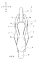
- FIG. 1 is a right side view of the entire vehicle as viewed from the right.
- FIG. 2 is a plan view of the entire vehicle 1 as viewed from above.
- FIG. 3 is a front view of the entire vehicle 1 as viewed from the front.
- FIG. 4 is a right side view of the entire vehicle viewed from the right when the movable part is in the second position.
- FIG. 5 is a plan view of the entire vehicle viewed from above when the movable portion is in the second position.
- FIG. 6 is a front view of the entire vehicle viewed from the front when the movable part is in the second position.
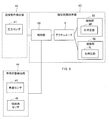
- FIG. 7 is a block diagram illustrating a configuration example of a control system provided in the vehicle 1.
- FIG. 8 is a block diagram showing a modification of the control system.
- FIG. 8 is a block diagram showing a modification of the control system.
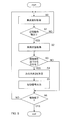
- FIG. 9 is a flowchart illustrating an example of a process for controlling the force applied to the contact portion.
- FIG. 10 is a block diagram illustrating a modification of the control system.
- FIG. 11 is a flowchart illustrating an operation example of the auditory stimulus presentation unit.
- FIG. 12 is a left side view of the vehicle in the modified example.
- FIG. 13 is a diagram illustrating a modification of the contact portion.
- FIG. 14 is a left side view of a vehicle portion including a contact portion and an actuator according to a modification.
- FIG. 15 is a top view of a vehicle portion including a contact portion and an actuator according to a modification.
- FIG. 16 is a perspective view of a vehicle portion including a contact portion and an actuator according to a modification.
- FIG. 17 is a cross-sectional view taken along line AA in FIG.
- FIG. 18 is a functional block diagram illustrating a configuration example of the vehicle aliveness perception promoting system.
- FIG. 19 is a diagram illustrating a modified example of the vehicle aliveness perception promoting system.
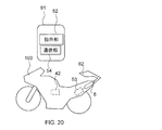
- FIG. 20 is a diagram illustrating another modified example of the vehicle aliveness perception promoting system.
- the arrow F indicates the front direction of the vehicle.
- Arrow B indicates the backward direction of the vehicle.
- An arrow U indicates the upward direction of the vehicle.
- An arrow D indicates the downward direction of the vehicle.
- An arrow R indicates the right direction of the vehicle.
- An arrow L indicates the left direction of the vehicle.
- the front-rear direction of the vehicle, the left-right direction of the vehicle, and the up-down direction of the vehicle mean the front-rear direction, the left-right direction, and the up-down direction with respect to the vehicle as viewed from the occupant driving the vehicle.
- the vehicle body frame may tilt in the left-right direction of the vehicle or the front-rear direction of the vehicle with respect to the vertical direction. Therefore, in addition to the direction based on the vehicle, the direction based on the vehicle body frame is determined.
- the front-rear direction, the left-right direction, and the up-down direction of the vehicle body frame coincide with the front-rear direction, the left-right direction, and the up-down direction of the vehicle, respectively. That is, the attached drawings show a state in which the vehicle stands upright without tilting left and right.
- the longitudinal direction of the vehicle body frame “the lateral direction of the vehicle body frame”, and “the vertical direction of the vehicle body frame” are the longitudinal direction with respect to the vehicle body frame as viewed from the occupant driving the vehicle, It means the horizontal direction and the vertical direction.
- extending forward in the front-rear direction of the body frame includes extending in a direction inclined with respect to the front-rear direction of the body frame.
- extending rearward in the front-rear direction of the body frame includes extending in a direction inclined with respect to the front-rear direction of the body frame.
- extending leftward in the left-right direction of the body frame includes extending in a direction inclined with respect to the left-right direction of the body frame.
- Extension rightward in the left-right direction of the body frame includes extending in a direction inclined with respect to the left-right direction of the body frame.
- extending upward in the vertical direction of the body frame includes extending in a direction inclined with respect to the vertical direction of the body frame.
- “Extending downward in the vertical direction of the body frame” includes extending in a direction inclined with respect to the vertical direction of the body frame.
- the “upright state of the body frame” means a state in which the vertical direction of the body frame coincides with the vertical direction. In this state, the direction based on the vehicle coincides with the direction based on the vehicle frame.
- the left-right direction of the vehicle does not match the left-right direction of the body frame
- the up-down direction of the vehicle does not match the up-down direction of the body frame.
- the front-rear direction of the vehicle and the front-rear direction of the body frame coincide.
- connection includes not only physical connection but also electrical connection and being in a communicable state.
- the physical connection includes, for example, a case where two members are directly connected and a case where two members are indirectly connected via other members.
- FIG. 1 is a right side view of the entire vehicle 1 as viewed from the right side.
- FIG. 2 is a plan view of the entire vehicle 1 as viewed from above.
- FIG. 3 is a front view of the entire vehicle 1 as viewed from the front.
- a vehicle 1 includes vehicle body frames 2a, 2b, 2c, and 2d (hereinafter, unless otherwise specified, vehicle body frames 2a to 2d are collectively referred to as vehicle body frame 2), seating seat 3, and front wheel support portion. 7R, 7L, front wheel 31, rear wheel 32, power unit 13, rear suspension 33, and rear arm 34. 2 and 3, the front wheel support portions 7R and 7L are composed of a right front wheel support portion 7R and a left front wheel support portion 7L, but in FIG. 1, only the right front wheel support portion 7R is included. It is shown.
- the vehicle body frame 2 supports the seating seat 3, the front wheel support portions 7R and 7L, and the power unit 13.
- the front wheel support portions 7R and 7L rotatably support the front wheel 31 at the front ends 71R and 71L (only the right front end 71R is shown in FIG. 1).
- the power unit 13 is suspended from the vehicle body frame 2.
- the power unit 13 includes a drive source such as an engine, an electric motor, and a battery, and a device such as a transmission.
- a rear arm 34 is attached to the rear portion of the vehicle body frame 2 so as to be rotatable about the pivot shaft 22.
- the rear arm 34 rotatably supports the rear wheel 32 at the rear end.
- One end of the rear suspension 33 is rotatably attached to the rear arm 34 and the other end is attached to the power unit 13.
- the other end of the rear suspension 33 may be attached to the vehicle body frame 2.
- the vehicle 1 includes a transmission member (for example, a chain, a belt, or a shaft) that transmits the driving force generated by the power unit to the rear wheel 32.
- the vehicle body frame 2 includes a frame 2a disposed at the center in the left-right direction and frames 2b, 2c, 2d connected to the frame 2a and disposed on the left and right of the frame 2a.
- the frame 2a extends in the front-rear direction while being curved.
- One end of the frame 2 a is connected to the seating seat 3.
- the frame 2a extends forward from the seating seat 3, curves downward, and then extends rearward.
- the other end, that is, the rear end of the frame 2 a supports the pivot shaft 22 of the rear arm 34.
- the frame 2 c branches from the frame 2 a and extends upward, and is connected to the base portion 4.
- the frame 2d branches from the frame 2a and extends downward behind the branch portion between the frame 2c and the frame 2a, and is connected to the frame 2b at the connection portion 21.
- the frame 2b extends upward from the connection portion 21, passes through the front of the frame 2c, and is connected to the guard 23 at a position above the frame 2a.
- the frames 2b, 2c, and 2d are each composed of a pair of frames arranged on the left and right sides of the frame 2a. As shown in FIG. 3, the frame 2b is arranged on the left and right of the frame 2a.
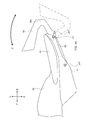
- the vehicle 1 includes a base portion 4 disposed in front of the seating seat 3, a movable portion 5 supported by the base portion 4, a right pressing portion 8R, and a left pressing portion 8L (in FIG. 1, the right pressing portion). Only 8R is shown).
- the base portion 4 is supported by the vehicle body frame 2.
- the movable part 5 is supported so as to be movable in the vertical direction with respect to the base part 4.
- the right pressing portion 8R and the left pressing portion 8L are supported so as to be movable in the left-right direction with respect to the base portion 4.
- the vehicle 1 includes actuators 61, 62, and 63 that move the movable portion 5, the right pressing portion 8R, and the left pressing portion 8L (hereinafter collectively referred to as the actuator 6 unless otherwise distinguished).
- the base part 4 is in contact with the front end of the seating seat 3 and extends forward from the seating seat 3.
- the supported portion of the movable portion 5 is disposed at a position overlapping the base portion 4 when viewed from the side (right side) of the vehicle 1.
- the movable part 5 is a supported part and is supported by the base part 4.
- the supported part is a pivot axis J1 of the movable part 5.
- the axial direction of the pivot shaft J1 is the same as the left-right direction of the body frame 2.
- the movable part 5 is formed to extend forward from the supported part.
- the movable part 5 is supported so as to be rotatable about a pivot axis J1. Accordingly, the movable portion 5 is supported so as to be movable in the vertical direction with respect to the base portion 4.
- the base portion 4 is disposed on the left and right of the supported portion of the movable portion 5. That is, the base portion 4 extends forward from the seating seat 3, branches to the left and right in the middle, and is connected to the right front wheel support portion 7 ⁇ / b> R and the left front wheel support portion 7 ⁇ / b> L, respectively.
- a pivot axis J1 of the movable part 5 is arranged between the base part 4 branched to the left and right.
- the base portion 4 is formed integrally with the front wheel support portions 7R and 7L. Specifically, the portion of the base portion 4 disposed on the right side of the movable portion 5 is connected to the right front wheel support portion 7R. Similarly, the portion of the base portion 4 disposed on the left side of the movable portion 5 is connected to the left front wheel support portion 7L.
- the base portion 4 is formed integrally with the right pressing portion 8R and the left pressing portion 8L. Specifically, the portion of the base portion 4 disposed on the right side of the movable portion 5 is connected to the right pressing portion 8R. Similarly, the part of the base part 4 arranged on the left side of the movable part 5 is connected to the left pressing part 8L.
- the right pressing portion 8R protrudes from the base portion 4 to the right.
- the left pressing portion 8L protrudes from the base portion 4 to the left.
- the right pressing portion 8 ⁇ / b> R is disposed at a position on the right side of the base portion 4 when viewed from above.
- the left pressing portion 8L is disposed at a position on the left side of the base portion 4 when viewed from above.
- the base 8Ra of the right pressing portion 8R with respect to the base portion 4 and the base 8La of the left pressing portion 8L with respect to the base portion 4 are positioned in front of the seating position of the occupant in the seating seat 3.
- the rear ends of the right pressing portion 8R and the left pressing portion 8L overlap with the seating position of the occupant in the front-rear direction of the body frame 2 when viewed from above. That is, the rear ends of the right pressing portion 8 ⁇ / b> R and the left pressing portion 8 ⁇ / b> L are located behind the front end of the seating seat 3.
- the base 8Ra of the right pressing portion 8R with respect to the base portion 4 is positioned on the right knee of the occupant straddling the seating seat 3.
- the base 8La of the left pressing portion 8L with respect to the base portion 4 is located on the left knee of the occupant straddling the seating seat 3. Therefore, the right pressing portion 8 ⁇ / b> R extends from the occupant's right knee straddling the seating seat 3 toward the right side of the trunk.
- the right pressing portion 8R and the left pressing portion 8L are configured to support the occupant's torso. In the occupant's body, the position where the right pressing portion 8R is in contact with the position where the left pressing portion 8L is in contact are different.
- the right pressing portion 8R and the left pressing portion 8L are examples of contact portions that are in contact with different portions of the occupant.
- the seat 3 is an example of an occupant support portion that is supported by the body frame and supports the occupant's body.
- a part of the right pressing part 8R overlaps a part of the movable part 5 and a part of the base part 4 when viewed from the right side.
- the right pressing portion 8R is formed to extend rearward and upward.
- the left pressing portion 8 ⁇ / b> L is provided at a position overlapping the right pressing portion 8 ⁇ / b> R when viewed from the left-right direction of the body frame 2. That is, a part of the left pressing part 8L overlaps a part of the movable part 5 and a part of the base part 4 when viewed from the left.
- the right pressing portion 8R and the left pressing portion 8L are supported by the vehicle body frame 2b via the base portion 4.
- the right pressing portion 8R and the left pressing portion 8L are supported movably in the left-right direction with respect to the base portion 4.
- the right pressing portion 8R includes a right fixed portion 8Rb and a right protruding movable portion 8Rc.
- the right fixing portion 8Rb is supported by the vehicle body frame 2.
- the right protruding movable portion 8Rc is movably supported by the right fixed portion 8Rb and extends rightward and rearward from the right fixed portion 8Rb.
- the right protruding movable portion 8Rc is rotatably supported with a line along the right end of the right fixed portion 8Rb as a rotation axis J2R.
- the rotation axis J2R is inclined with respect to the longitudinal axis of the body frame 2.
- the front end of the rotation axis J2R is located to the right of the rear end.
- the left pressing portion 8L includes a left fixed portion 8Lb and a left protruding movable portion 8Lc.
- the left fixed portion 8Lb is supported by the vehicle body frame 2.
- the left protruding movable portion 8Lc is movably supported by the left fixed portion 8Lb and extends leftward and rearward from the left fixed portion 8Lb.
- the left projecting movable portion 8Lc is rotatably supported with a line along the left end of the left fixed portion 8Lb as a rotation axis J2L.
- the rotation axis J2L is inclined with respect to the longitudinal axis of the body frame 2.
- the front end of the rotation axis J2L is located to the left of the rear end.
- the actuator 6 that moves the right pressing portion 8R and the left pressing portion 8L can use, for example, a motor 61 as a power source.
- wires 81 ⁇ / b> R and 81 ⁇ / b> L are provided as means for transmitting the power of the motor 61.
- the wires 81R and 81L are wound around a winder 64 fixed to the vehicle body frame 2.
- the winder 64 is driven by a motor 61.
- One end of the wire 81R is attached to the winder 64.
- the other end of the wire 81R is attached at a position away from the rotation axis J2R of the right protruding movable portion 8Rc.
- the wire 81R intersects the rotation axis J2R.
- One end of the wire 81L is attached to the winder 64.
- the other end of the wire 81L is attached to a position away from the rotation axis J2L of the left protruding movable portion 8Lc.
- the wire 81L intersects the rotation axis J2L.
- the right protruding movable portion 8Rc and the left protruding movable portion 8Lc move so as to approach each other.
- the right press part 8R and the left press part 8L can push a passenger
- the power to contain arises.
- the mechanism for moving the right pressing portion 8R and the left pressing portion 8L so as to approach each other is not limited to the above example.
- a motor can be provided in each of the right pressing portion 8R and the left pressing portion 8L. That is, a right motor that drives the right pressing portion 8R and a left motor that drives the left pressing portion 8L may be provided.
- the output shaft of the right motor can be arranged in parallel to the rotation axis J2R of the right protruding movable portion 8Rc. And you may provide the transmission member which transmits rotation of the output shaft of a right motor to the right protrusion movable part 8Rc.
- the right protruding movable portion 8Rc rotates around the rotation axis J2R as the output shaft of the right motor rotates.
- the output shaft of the left motor may be arranged in parallel to the rotation axis J2L of the left protruding movable portion 8Lc.
- the left protruding movable portion 8Lc rotates around the rotation axis J2L as the output shaft of the left motor rotates.
- the right motor and the left motor can be controlled by the same control signal, for example.
- the right pressing portion 8R and the left pressing portion 8L may each have a configuration in which an airbag is provided in a portion in contact with the occupant.
- the vehicle 1 can be provided with a compressor as an actuator and an air pipe connecting the compressor and the airbag.
- the compressor can be driven by, for example, a motor or an engine.
- the air pipe can be provided with an air valve. By controlling the opening and closing of the air valve, the amount of air enclosed in the airbag can be adjusted by the pressure of the compressor.
- the airbags of the right pressing portion 8R and the left pressing portion 8L approach each other. Thereby, force can be applied in a direction in which different parts of the occupant's body are brought closer to each other.
- the actuator may be configured to include both a motor and an air compressor.
- a mechanism for rotating the right protruding movable portion 8Rc and the left protruding movable portion 8Lc around the rotation axes J2R and J2L by the motor 61 and a mechanism for inflating the right protruding movable portion 8Rc and the left protruding movable portion 8Lc by the airbag Both can be provided in the vehicle 1.
- the actuator 6 that moves the right pressing portion 8R and the left pressing portion 8L includes a motor 61, a winder 64, and wires 81R and 81L.
- the actuator 6 that moves the movable portion 5 includes a motor 61 and speed reducers (gears) 62 and 63 as shown in FIG.
- the rotation of the output shaft of the motor 61 is transmitted to the pivot shaft J1 via the speed reducers 62 and 63.
- the output shaft of the motor 61 and the rotation shafts of the speed reducers 62 and 63 are parallel to the pivot shaft J1.
- the speed reducer 62 is coaxial with the output shaft of the motor 61 and rotates as the output shaft of the motor 61 rotates.
- the reduction gear 63 is coaxial with the pivot shaft J ⁇ b> 1 and meshes with the reduction gear 62.
- the speed reducer 62 rotates
- the speed reducer 63 rotates.
- the pivot shaft J1 rotates.
- the configuration of the actuator 6 that moves the movable portion 5 is not limited to the example shown in FIG.
- the front wheel support portion 7 ⁇ / b> R extends from the base portion 4 forward and downward toward the front wheel 31.
- the front wheel support portion 7 ⁇ / b> R is formed continuously with the base portion 4.
- the front wheel support portion 7L extends from the base portion 4 to the front wheel 31 forward and downward through the left of the movable portion 5 (see FIGS. 2 and 3).
- the front wheel support portion 7L is formed continuously with the base portion 4.
- a groove 11 is formed on the right side surface of the front wheel support portion 7 ⁇ / b> R, extending forward and downward from the base portion 4 toward the front wheel 31.
- the groove 11 is a portion where the right side surface of the front wheel support portion 7R is recessed toward the inside of the vehicle.
- the groove 11 has a bottom surface that extends forward and downward, and a pair of side surfaces that face each other in a direction perpendicular to the direction in which the bottom surface extends.
- a grip portion 12 is provided in a recess formed by the groove 11.
- the grip portion 12 is formed of a rod-shaped member that extends from one of a pair of side surfaces of the groove 11 facing each other toward the other.
- a groove 11 is formed on the left side surface of the front wheel support portion 7L, extending forward and downward from the base portion 4 toward the front wheel 31 (see FIGS. 2 and 3).
- the groove 11 is a portion where the left side surface of the front wheel support portion 7L is recessed toward the inside of the vehicle.
- the groove 11 has a bottom surface that extends forward and downward, and a pair of side surfaces that face each other in a direction perpendicular to the direction in which the bottom surface extends.
- a grip portion 12 is provided in a recess formed by the groove 11.
- the grip portion 12 is formed of a rod-shaped member that extends from one of a pair of side surfaces of the groove 11 facing each other toward the other.
- the gripping part 12 is a part that the occupant straddling the seating seat 3 grips with a hand.
- the grip unit 12 is provided with a pressure sensor 41.
- the pressure sensor 41 detects the pressure applied to the grip portion 12 by the passenger's hand.
- the pressure sensor 41 can detect an operation in which the occupant grips the grip portion 12, that is, an operation in which the occupant's finger and palm are brought close to each other.
- the pressure sensor 41 is an example of a proximity operation detection unit that detects an operation in which parts of the occupant's body that are separated from each other approach.
- the occupant's fingers and palm correspond to the parts of the occupant's body that are separated from each other.
- the grip portion 12 may be provided with a brake operator.
- the upper surface of the base portion 4 is continuous with the upper surfaces of the seating seat 3, the front wheel support portions 7L and 7R, the right pressing portion 8R, and the left pressing portion 8L.
- the upper surfaces can be configured to be continuous.
- FIGS. 4, 5 and 6 show the vehicle 1 in a state where the right pressing portion 8R and the left pressing portion 8L are in the second position.
- the first position is such that the right protruding movable portion 8Rc of the right pressing portion 8R is tilted to the right with respect to the vertical line of the body frame 2 around the rotation axis J2R.
- the left projecting movable portion 8Lc of the left pressing portion 8L is rotated in the direction of tilting to the left with respect to the vertical line of the body frame 2 around the rotation axis J2L.
- the second position is a direction in which the right protruding movable portion 8Rc of the right pressing portion 8R approaches the vertical line of the vehicle body frame 2 about the rotation axis J2R.
- the left projecting movable portion 8Lc of the left pressing portion 8L is rotated in a direction approaching the vertical line of the vehicle body frame 2 around the rotation axis J2L.
- the distance in the left-right direction between the right end of the right press portion 8R and the left end of the left press portion 8L when the right press portion 8R and the left press portion 8L are in the second position is the right press portion 8R and It is shorter than the distance in the left-right direction between the right end of the right press portion 8R and the left end of the left press portion 8L when the left press portion 8L is in the first position (see FIG. 2). That is, in the second position, the distance between the right pressing portion 8R and the left pressing portion 8L is narrower than that in the first position. That is, at the second position, the right pressing portion 8R and the left pressing portion 8L are closer to each other than the first position.
- the right pressing portion 8R and the left pressing portion 8L are in the second position, the right pressing portion 8R and the left pressing portion 8L are in the horizontal direction with respect to the vertical direction line of the body frame 2.
- the right pressing portion 8 ⁇ / b> R and the left pressing portion 8 ⁇ / b> L are in the first position, the right pressing portion 8 ⁇ / b> R and the left pressing portion 8 ⁇ / b> L are laterally moved with respect to the vertical direction line of the body frame 2.
- the right pressing portion 8R can be tilted to the right with respect to the vertical axis of the vehicle body frame 2 by the actuator. Further, the actuator can tilt the left pressing portion 8L to the left with respect to the vertical axis of the vehicle body frame 2.
- the actuator 6 can move the right pressing portion 8R and the left pressing portion 8L between the first position and the second position.
- the actuator 6 applies a force including a component in a direction in which the right pressing portion 8R and the left pressing portion 8L are brought closer to each other.
- the force applied by the actuator 6 is controlled based on the movement of the occupant detected by the pressure sensor 41.
- FIG. 7 is a block diagram illustrating a configuration example of a control system provided in the vehicle 1.
- the control system illustrated in FIG. 7 includes a proximity motion detection unit 42 and a tactile stimulus presentation unit 43.
- the proximity movement detection unit 42 detects a movement in which the separated parts of the body of the occupant supported by the seating seat 3 (occupant support part) approach each other.
- the proximity movement detection unit 42 includes a pressure sensor 41 as an example.
- the pressure sensor 41 detects the pressure applied to the grip portion 12 by the hand of the passenger gripping the grip portion 12.
- the tactile stimulus presentation unit 43 includes a control unit 68, an actuator 6, and two contact units 82.
- the two contact portions 82 are parts of the vehicle body and are in contact with different parts of the occupant's body.
- the two contact portions 82 include a right pressing portion 8R and a left pressing portion 8L, respectively.
- the actuator 6 applies a force including a component that brings the two contact portions 82 closer to each other in the direction connecting the two contact portions 82 to at least one of the two contact portions 82.
- the actuator 6 applies a force including components in a direction approaching each other to the right pressing portion 8R and the left pressing portion 8L.
- the control unit 68 controls the force applied to the contact unit 82 by the actuator 6 based on the occupant's motion detected by the proximity motion detection unit 42.
- control unit 68 acquires the detection result of the proximity motion detection unit 42.
- the control unit 68 receives a signal indicating the pressure of the gripping unit 12 detected by the pressure sensor 41.
- the control unit 68 generates a control signal based on the received signal indicating the pressure, and supplies the generated control signal to the actuator 6.
- the control unit 68 can control the actuator 6 by supplying a signal indicating the current value of the motor 61 of the actuator 6 to the motor 61.
- the control unit 68 can be configured by a computer such as an ECU or an electronic circuit.
- a computer board or a circuit board on which an electronic circuit constituting the control unit 68 is mounted may be built in a housing that houses the actuator 6, or may be provided outside the housing that houses the actuator 6.
- the control unit 68 applies a force including a component that causes the actuator 6 to bring the two parts of the contact unit 82 closer to each other. 82 can be controlled.
- the control unit 68 controls the actuator 6 to bring the right pressing unit 8R and the left pressing unit 8L closer to each other when the pressure detected by the pressure sensor 41 exceeds a threshold value.
- the right pressing portion 8R and the left pressing portion 8L can be controlled to press the occupant's torso from the left and right.
- control unit 68 may adjust the magnitude or timing of the force applied to the contact unit 82 by the actuator 6 according to the occupant motion detected by the proximity motion detection unit 42.
- the control unit 68 can change the magnitude of the force applied to the contact unit 82 in accordance with the detected amount of occupant movement.
- the magnitude of the force by which the actuator 6 moves the right pressing portion 8R and the left pressing portion 8L can be controlled according to the pressure detected by the pressure sensor 41. Thereby, for example, according to the force gripped by the occupant, the force by which the right pressing portion 8R and the left pressing portion 8L press the occupant's trunk from the left and right can be changed.
- control unit 68 determines the speed of moving the contact portion 82 or the timing of applying the force of the occupant detected by the proximity motion detection unit. You may control according to operation
- control unit 68 can determine the control value (control data) for controlling the force by the actuator 6 from the detection value indicating the motion of the occupant detected by the proximity motion detection unit 42.
- the process of determining the control value of the actuator 6 using the value indicating the movement of the occupant can be, for example, a process of calculating the control value using a predetermined mathematical formula using the detected value as a parameter.
- the control unit 68 uses control data corresponding to the detection acquired from the proximity motion detection unit 42 using data (for example, table or map data) in which various detection values and control values corresponding thereto are recorded. It is also possible to execute a process for determining.
- the control unit 68 may receive information from two or more sensors as the occupant motion detected by the proximity motion detection unit 42.
- a knee grip pressure sensor that detects the pressure of the knee grip can be provided in the vehicle 1.
- the control unit 68 controls the force applied by the actuator 6 to the right pressing unit 8R and the left pressing unit 8L using signals acquired from both the pressure sensor of the grip unit 12 and the knee grip pressure sensor. Can do.
- the actuator 6 may be configured to apply force to two or more sets of contact portions 82.
- another contact portion can be provided in the vehicle 1.
- the airbag can be disposed at a position surrounding the grip portion 12 in the groove 11. By inflating the airbag, the airbag can be configured to push the back and fingers of the occupant's hand holding the grip portion 12.
- the vehicle 1 can be provided with a compressor as the actuator 6, an air pipe connecting the compressor and the air bag, and an air valve provided in the air pipe.
- the control unit 68 controls both the actuator 6 that moves the right pressing unit 8R and the left pressing unit 8L and the air valve. The control unit 68 can perform these controls based on the occupant motion detected by the proximity motion detection unit 42.
- FIG. 8 is a block diagram illustrating a configuration example of a control system in which the control unit 68 can control the force applied to the contact unit 82 by the actuator using the vehicle state.
- the control system shown in FIG. 8 includes a vehicle state detection unit 44.
- the vehicle state detection unit 44 is provided in the vehicle 1 and detects a physical quantity indicating the state of the vehicle.
- a vehicle speed sensor 45 and an inclination angle sensor 46 are included in the vehicle state detection unit 44.
- the control unit 68 controls the force applied to the contact unit 82 by the actuator 6 based on the vehicle state detected by the vehicle state detection unit 44. For example, the control unit 68 can adjust the force applied by the actuator 6 to the contact unit 82 according to the vehicle speed detected by the vehicle speed sensor 45.
- FIG. 9 is a flowchart showing an example of a process for controlling the force applied to the contact portion based on the movement of the occupant and the vehicle state.
- the control unit 68 acquires information related to the occupant's motion from the proximity motion detection unit 42 (S ⁇ b> 0). For example, the control unit 68 acquires a signal indicating the pressure applied to the gripping unit 12 from the hand gripping the gripping unit 12 from the pressure sensor 41 provided in the gripping unit 12.
- the control unit 68 detects, based on a signal from the proximity motion detection unit 42, that the occupant has performed an action of bringing body parts that are separated from each other (hereinafter referred to as a proximity motion) (YES in S1). For example, the control unit 68 determines that there is a proximity operation when the pressure detected by the pressure sensor 41 of the gripping unit 12 exceeds a threshold value. In this example, the pressure sensor 41 detects an operation in which the occupant brings a finger and a palm close to each other as parts of the body separated from each other.
- the control unit 68 acquires information indicating the vehicle state from the vehicle state detection unit 44 (S2). For example, the control unit 68 acquires, as information indicating the vehicle state, a signal indicating a physical quantity indicating the vehicle state resulting from the movement of the occupant. As a specific example, the control unit 68 acquires a signal indicating the vehicle speed from the vehicle speed sensor 45.
- the control unit 68 determines whether or not to apply a force to bring the contact unit 82 closer based on the vehicle state acquired in S2 (S3). For example, the control unit 68 determines to apply a force when the vehicle speed detected by the vehicle speed sensor 45 is within a predetermined range (YES in S3). When it is determined that no force is applied (NO in S3), the control unit 68 executes a determination process (S6) for determining whether to end the control.
- the control unit 68 determines the magnitude of the force that brings the contact parts 82 closer to each other (S4).
- the control unit 68 can determine the magnitude of the force by using the proximity operation detected in S1 and the information regarding the vehicle state acquired in S2. For example, the magnitude of the force that brings the contact portion 82, that is, the right pressing portion 8R and the left pressing portion 8L closer to each other, is determined according to the pressure of the pressure sensor 41 acquired in S1 and the vehicle speed acquired in S2. For example, referring to correspondence data indicating the correspondence between the vehicle state recorded in advance and the magnitude of the applied force, the magnitude of the force corresponding to the pressure of the pressure sensor 41 acquired in S0 and the vehicle speed acquired in S1 is determined. be able to.
- the control unit 68 may determine the timing for applying the force, the speed at which the contact unit 82 is moved, or other control content, instead of or in addition to the magnitude of the force.
- the control unit 68 supplies a control signal based on the content determined in S4 to the actuator 6 (S5). As a result, the actuator 6 applies a force having a magnitude determined in S4 to the contact portion 82.
- the control unit 68 repeats the processes of S0 to S5 until it is determined that the control is finished (YES in S6).
- the operation of the control unit 68 is not limited to the example shown in FIG.
- the process of S3 may be omitted.
- the process of S2 can be omitted.
- the force to be applied is determined based on the approaching action of the occupant acquired in S0.
- the vehicle state acquired in S2 is not limited to the vehicle speed, but in addition to or in place of the vehicle speed, the brake operation amount, the throttle opening, the left-right inclination amount or speed, the slip ratio, the engine speed, and the like
- the vehicle state can be acquired.
- the determination process of the output sound in S4 is not limited to the process using the corresponding data recorded in advance as described above.
- the magnitude, speed, or timing of the force can be determined by processing a value indicating an occupant's motion or vehicle state according to a predetermined mathematical expression or algorithm.
- the pressure with which the occupant grips the grip portion 12 can be returned to the occupant's torso via the contact portion 82.
- the vehicle 1 can give the occupant a tactile stimulus corresponding to an operation of grasping the occupant's hand.
- the torso is tightened, so that the occupant feels hugged by the vehicle 1.
- FIG. 10 is a block diagram illustrating a modification of the control system provided in the vehicle 1.
- the control system shown in FIG. 10 includes an auditory stimulus presentation unit 47 in addition to the proximity motion detection unit 42 and the tactile stimulus presentation unit 43.
- the auditory stimulus presentation unit 47 outputs a sound including the feature amount of the exclamation voice based on the motion detected by the proximity motion detection unit 42.
- the auditory stimulus presentation unit 47 includes a control unit 58 and a speaker 48.
- the control unit 58 of the auditory stimulus presentation unit 47 can determine whether or not to output an exclamation voice based on the motion detected by the proximity motion detection unit 42. That is, the control unit 58 determines whether or not to output an exclamation sound based on the motion detected by the proximity motion detection unit 42 and approaching parts separated from each other in the body of the occupant straddling the seating seat 3. For example, the control unit 58 can determine to output an exclamation sound when the detected amount of motion is within a predetermined range. In this case, the control unit 58 causes the speaker 48 to output an exclamation sound.
- control unit 58 of the auditory stimulus presentation unit 47 may determine an exclamation sound to be output based on the motion detected by the proximity motion detection unit 42. For example, the control unit 58 can select voice data to be output from voice data of exclamation voice recorded in advance based on the motion detected by the proximity motion detection unit 42. The control unit 58 causes the speaker 48 to output an exclamation voice of the selected voice data. For example, the control unit 58 can change the excitement sound to be output according to the amount of motion detected.
- the auditory stimulus presentation unit 47 outputs an exclamation sound based on the motion detected by the proximity motion detection unit 42, so that the excitement voice is provided in accordance with the application of force through the contact unit 82 by the tactile stimulus presentation unit 43. Can be output.
- the tactile stimulus presentation unit 43 can output an exclamation sound in accordance with the timing when the contact unit 82 applies force to the occupant's body. That is, the application of force by the tactile stimulus presentation unit 43 and the output of the exclamation sound by the auditory stimulus presentation unit 47 can be synchronized. For example, the application of force by the tactile stimulus presentation unit 43 and the output of the exclamation voice by the auditory stimulus presentation unit 47 can be performed simultaneously. The occupant can feel more attachment to the vehicle 1.
- the exclamation voice is a voice that represents human emotions regardless of language.
- the exclamation voice is, for example, a voice that expresses human emotions by inflection of the height or magnitude of the sigh sound.
- the exclamation voice may be a synthesized voice of a person's breath and other sounds (for example, engine sounds). Examples of exclamation sounds include screams, squeals, laughter, pant voices, sighs, whistle, and the like.
- a scream or cry represents surprise, anger, sadness, or the like.
- Laughter and whistle represent relaxation, enjoyment, joy and so on.
- the pant voice represents excitement, pain, pleasure, and the like.
- a sigh represents fatigue, compliment, etc.
- the tactile stimulus presentation unit 43 and the auditory stimulus presentation unit 47 increase the hold pressure on the occupant's trunk by the contact unit 82 and synthesize the exclamation voice with the engine sound when the occupant strongly grasps the grip unit 12. Sound can be presented. As a result, the occupant strengthens the feeling of hugging the vehicle 1. The occupant can feel more attachment to the vehicle 1.
- the auditory stimulus presentation unit 47 may be configured to output an exclamation sound when the tactile stimulus presentation unit 43 determines to apply force to the occupant's body from the contact unit 82.
- an exclamation sound is indirectly output based on the detection result of the proximity motion detection unit 42.
- Such a form is also included in the output of the exclamation sound based on the motion detected by the proximity motion detection unit 42.
- the control unit 58 of the tactile stimulus presentation unit 43 may further control the exclamation voice output by using the vehicle state in addition to the operation detected by the proximity motion detection unit 42. For example, when the control unit 58 determines to output the exclamation sound based on the motion detected by the proximity motion detection unit 42, the control unit 58 determines the exclamation sound to be output based on the vehicle state detected by the vehicle state detection unit 44. can do. Thereby, an appropriate exclamation sound according to the vehicle state can be output.
- FIG. 11 is a flowchart showing an operation example of the auditory stimulus presentation unit 47.
- S0, S1, and S2 in FIG. 11 can be the same processing as S0, S1, and S2 shown in FIG.
- the control unit 68 of the auditory stimulus presentation unit 47 determines whether or not to output an exclamation voice based on the vehicle state acquired in S2 (S13). For example, when the vehicle speed detected by the vehicle speed sensor 45 is within a predetermined range, the control unit 68 determines to output an exclamation sound (YES in S13). When it is determined that no force is applied (NO in S13), the control unit 68 executes a determination process (S6) for determining whether to end the control.
- the control unit 68 determines the exclamation sound to be output (S14).
- the control unit 68 can determine the excitement sound to be output using the information regarding the proximity movement detected in S ⁇ b> 1 and the vehicle state acquired in S ⁇ b> 2. For example, the control unit 68 determines the exclamation sound according to the pressure of the pressure sensor 41 acquired in S0 and the vehicle speed acquired in S2.
- a plurality of exclamation voice data files can be recorded in advance in a memory accessible by the control unit 58.
- condition data indicating conditions for the proximity movement and the vehicle state is also recorded in the memory in advance.
- the control unit 58 refers to the condition data and identifies the condition data that satisfies the conditions of the proximity movement acquired in S0 and the vehicle state acquired in S2.
- the voice data file corresponding to the specified condition data is determined as the excitement voice to be output.
- the control unit 68 reproduces the audio data file determined in S14, generates an audio signal, and supplies the audio signal to the speaker 48 (S15). Thereby, the speaker 48 outputs the exclamation sound determined in S14.
- the control unit 68 repeats the processes of S0 to S15 until it is determined that the control is finished (YES in S6).
- the pressure at which the occupant grips the grip portion 12 can be returned to the occupant's torso via the contact portion 82.
- the vehicle 1 can give the occupant a tactile stimulus corresponding to an operation of grasping the occupant's hand.
- the torso is tightened, so that the occupant feels hugged by the vehicle 1.
- the operation of the auditory stimulus presentation unit 47 is not limited to the example shown in FIG.
- the process of S13 may be omitted.
- the process of S2 can be omitted.
- the exclamation voice is determined based on the approaching action of the occupant acquired in S0.
- the vehicle state acquired in S2 is not limited to the vehicle speed, but in addition to or in place of the vehicle speed, the brake operation amount, the throttle opening, the left-right inclination amount or speed, the slip ratio, the engine speed, and the like
- the vehicle state can be acquired.
- the output sound determination process in S14 is not limited to the process using condition data recorded in advance as described above.
- the excitement voice can be determined by processing values indicating the occupant's movement and the vehicle state according to a predetermined mathematical expression or algorithm.
- FIG. 12 is a left side view of the vehicle in the modified example.
- a vehicle 100 shown in FIG. 12 is a motorcycle.
- the vehicle 100 includes a body frame 10, a power unit 18, front wheels 31, rear wheels 32, and a fuel tank 30.
- the vehicle body frame 10 includes a head pipe 24, a tank frame 25, a rear frame 35, and a rear arm 14.
- the head pipe 24 is disposed at the front portion of the vehicle body frame 10.
- the tank frame 25 is configured as a pair of left and right.
- the tank frame 25 extends rearward from the head pipe 24.
- the pair of left and right tank frames 25 each have a portion that curves downward.
- a pair of left and right rear frames 35 are connected to the curved portion of the tank frame 25.
- the rear arm 14 is connected to the rear end of the tank frame 25.
- a step 28 protruding in the left-right direction is attached to the rear ends of the pair of left and right tank frames 25.
- a steering shaft 17 is rotatably inserted into the head pipe 24.
- a handle 16 is attached to the upper portion of the steering shaft 17.
- a pair of left and right front forks 15 are attached to the steering shaft 17 via brackets (not shown).
- a front wheel 31 is rotatably supported at the lower end of the front fork 15. As the handle 16 is operated, the front wheel 31 rotates in the left-right direction.
- a rear wheel 32 is rotatably supported at the rear end of the rear arm 14. The rear wheel 32 rotates when the power of the power unit 18 is transmitted.
- the fuel tank 30 is attached to the tank frame 25 and the rear frame 35.
- a seating seat 19 is disposed behind the fuel tank 30.
- the front part of the seat 19 covers a part of the rear part of the fuel tank 30.
- the handle 16 includes a grip 16a that is a portion gripped by the occupant.
- a pressure sensor 41 is attached to the grip 16 a of the handle 16. The pressure sensor 41 detects the movement of the occupant gripping the grip 16a, that is, the movement of bringing the finger and palm close together.
- a front cowl 36 is disposed in front of the handle 16.
- a cover 26 is disposed behind the handle 16.
- the rear part of the cover 26 covers a part of the front part of the fuel tank 30.
- a pair of left and right base portions 27 are disposed below the cover 26.
- the base portion 27 is attached to the tank frame 25 and the rear frame 35.
- Base portion 27 covers a part of the lower portion of fuel tank 30 in a side view of vehicle 100.
- the base portion 27 covers a part of the front portion of the seating seat 19 in a side view of the vehicle 100.
- the left and right pair of base portions 27 are respectively provided with a right pressing portion 83R and a left pressing portion 83L (only the right pressing portion 83R is shown in FIG. 12).
- the right pressing portion 83R and the left pressing portion 83L are supported by the base portion 27.
- the right pressing portion 83R and the left pressing portion 83L are formed to extend rearward and upward from the base portion 27.
- the right pressing portion 83R and the left pressing portion 83L are arranged from the vicinity of the occupant's knees with the feet placed on the step 28 across the seating seat 19 to the side of the occupant's torso.
- the right pressing portion 83R and the left pressing portion 83L are contact portions that respectively contact the right side and the left side of the occupant's torso.
- the ends of the right pressing portion 83R and the left pressing portion 83L that are separated from the base portion 27 are configured to be movable in directions toward each other.
- an airbag (not shown) may be provided on each of the left surface at the rear end of the right pressing portion 83R and the right surface at the end portion of the left pressing portion 83L.
- vehicle 100 includes a compressor (not shown) as an actuator.
- the airbag is connected to the compressor via an air pipe.
- An air valve is provided in the air pipe. By controlling the opening and closing of the air valve, the amount of air enclosed in the airbag of the right pressing portion 83R and the left pressing portion 83L is adjusted.
- the right pressing portion 83R and the left pressing portion 83L move in directions that approach each other. Accordingly, the right pressing portion 83R and the left pressing portion 83L simultaneously press the right side and the left side of the occupant's torso.
- the mechanism for moving the right pressing portion 83R and the left pressing portion 83L in a direction approaching each other is not limited to the above example.
- the right pressing portion 83R and the left pressing portion 83L may be configured to be swingable in the left-right direction.
- the vehicle 100 includes a control system similar to that shown in FIG.
- the vehicle 100 includes the pressure sensor 41 as the proximity movement detection unit 42, and includes the right pressing unit 83R and the left pressing unit 83L as the two contact units 82.
- the vehicle 100 includes a control unit 68 and an actuator 6.
- the actuator 6 applies a force including a component that brings the two contact portions 82 closer to each other to at least one of the two contact portions 82.
- the control unit 68 controls the force that the actuator 6 applies to the contact unit 82 based on the pressure detected by the pressure sensor 41.
- the haptic stimulus presentation unit 43 can increase the pressure held by the occupant's torso by the right pressing unit 83R and the left pressing unit 83L in response to the operation of the occupant gripping the grip 16a of the handle 16. Therefore, the occupant can feel as if he / she is hugged from the vehicle body according to his / her emotional movement. As a result, the degree of attachment of the occupant to the vehicle can be improved.
- the structure of the base part 27 is not restricted to the example shown in FIG.
- the base portion 27 may be attached to the handle 16.
- the fuel tank 30 can be used as a base part, or the base part 27 can be attached to the fuel tank 30.
- the right pressing portion 83R and the left pressing portion 83L can be configured by members protruding from the base portion 27.
- the cover 26 can be used as the base portion 27, and the right pressing portion 83R and the left pressing portion 83L can be attached to the cover 26.
- the right pressing part 83R and the left pressing part 83L which are two contact parts, are arranged side by side in the left-right direction.
- the arrangement of the two contact portions is not limited to this.
- a front pressing part and a rear pressing part may be arranged before and after the seating sheet 19.
- the seat 19 can be used as the base portion.
- a pressing part can be arranged at the rear part of the seating seat 19 and the occupant's back can be pushed by the pressing part. In this case, for example, a force including a component in a direction in which the abdomen of the occupant in contact with the fuel tank 30 and the back in contact with the pressing portion approach each other is applied.
- FIG. 13 is a diagram illustrating a modification of the contact portion.
- FIG. 13 is a cross-sectional view of the grip portion of the handle 16 of the vehicle 100.
- a grip cover 32 that covers the front and upper sides of the grip 16 a of the handle 16 is provided.
- a lever 29 is disposed in front of the grip 16 a and behind the grip cover 32.
- airbags 84F and 84U are attached to the front surface of the grip 16a and the upper surface of the grip 16a, respectively. That is, the airbags 84F and 84U are attached to two locations that are separated from each other in the front-rear direction and the vertical direction in the space between the grip cover 32 and the grip 16a.
- the airbags 84F and 84U serve as two contact portions that are in contact with different portions of the passenger's hand.
- forces are applied to different portions of the passenger's hand from above and from the front.
- These two forces include components in the direction in which the two contact portions approach each other. That is, by inflating the airbags 84F and 84U, a force including a component that brings the two contact portions closer in the direction connecting the airbags 84F and 84U, which are the two contact portions, is applied.
- a force including a component that brings the two contact portions closer in the direction connecting the airbags 84F and 84U, which are the two contact portions is applied.
- the occupant feels as if the hand is placed on the back of the hand.
- FIG. 14 to 17 are diagrams showing modifications of the contact portion and the actuator.
- FIG. 14 is a left side view illustrating a configuration of a vehicle portion including the contact portion 85 and the actuator 65 according to the modification as viewed from the left side of the vehicle.
- FIG. 15 is a top view of a portion of the vehicle including the contact portion 85 and the actuator 65 as viewed from above the vehicle.
- FIG. 16 is a perspective view of a portion of the vehicle including the contact portion 85 and the actuator 65 as viewed obliquely from the lower left rear. 17 is a cross-sectional view taken along line AA in FIG.
- the contact portion 85 is supported by the vehicle body frame 37 so as to be rotatable about the first pivot axis J3.
- a seat 19 is attached to the body frame 37.
- the body frame 37 can be, for example, a rear frame at the rear of the vehicle.
- An actuator 65 that rotates the contact portion 85 is further attached to the body frame 37.
- the actuator 65 is provided on the opposite side of the body frame 37 from the seat 19. That is, the vehicle body frame 37 that supports the seating seat 19 and the actuator 65 is disposed.
- the contact portion 85 has a shape that bends toward an occupant seated on the seat 19. That is, the contact portion 85 has a shape that extends rearward from the first pivot axis J3 and then bends and extends in a direction approaching the seating seat 19. In other words, the contact portion 85 has a bent portion 85c that bends toward the seating seat 19 in the rotation circumferential direction Y of the first pivot shaft J3 that is the rotation shaft.
- the contact portion 85 is configured so that the contact portion 85 can contact the occupant seated on the seat 19 from the rear in the front-rear direction of the vehicle by rotating the contact portion 85 about the first pivot axis J3.
- the axial direction of the first pivot shaft J ⁇ b> 3 of the contact portion 85 is the same as the left-right direction of the vehicle body frame 37.
- the first pivot shaft J3 may not be the same as the left-right direction of the body frame 37.
- the contact part 85 has a right pressing part 85aR and a left pressing part 85aL.
- the right pressing portion 85aR is in contact with the back surface of the occupant seated on the seating seat 19, that is, the right side of the back.
- the left pressing portion 85aL is in contact with the back surface of the occupant's torso, that is, the left side of the back.
- the right pressing portion 85 a ⁇ / i> R and the left pressing portion 85 a ⁇ / i> L are formed in a portion closer to the tip than the bent portion 85 c of the contact portion 85.
- the contact portion 85 is branched into a right pressing portion 85aR and a left pressing portion 85aL at the bent portion 85c.
- Each of the right pressing portion 85aR and the left pressing portion 85aL extends from the bent portion 85c in the direction approaching the seating seat 19 in the circumferential direction Y of rotation around the first pivot axis J3.
- the surface where the right pressing portion 85aR contacts the occupant and the surface where the left pressing portion 85aL contacts the occupant are not parallel to each other.
- the surface where the right pressing portion 85aR contacts the occupant and the surface where the left pressing portion 85aL contacts the occupant face each other in the left-right direction of the vehicle.
- at least a part of the right pressing part 85aR and at least a part of the left pressing part 85aL overlap.
- the surface facing the occupant of the right pressing portion 85aR and the surface facing the occupant of the left pressing portion 85aL are both flat. Note that these surfaces may be curved surfaces.
- the right pressing portion 85aR and the left pressing portion 85aL are pressed against the occupant in one direction.
- the direction in which the right pressing portion 85aR and the left pressing portion 85aL are pressed against the occupant is the circumferential direction Y of the rotation of the contact portion 85 around the first pivot axis J3.
- the normal of the surface where the right pressing portion 85aR contacts the occupant and the normal of the surface where the left pressing portion 85aL contacts the occupant are in the direction in which the right pressing portion 85aR and the left pressing portion 85aL are pressed against the occupant.
- the vehicle is tilted in the left-right direction.
- the distance between the right pressing portion 85aR and the left pressing portion 85aL becomes narrower as the distance from the occupant increases in the direction in which they are pressed against the occupant (circumferential direction Y). That is, the space between the right pressing portion 85aR and the left pressing portion 85aL is such that the space between the right pressing portion 85aR and the left pressing portion 85aL becomes narrower as the distance from the passenger increases in the direction in which the right pressing portion 85aR and the left pressing portion 85aL are pressed against the passenger.
- a pressing portion 85aL is formed.
- the right pressing portion 85aR and the left pressing portion 85aL are integrally moved by one actuator 65.
- the structure by which a right press part and a left press part are independently moved by an actuator may be sufficient.
- the actuator 65 is connected between the contact portion 85 and the vehicle body frame 37.
- One end 65e of the actuator 65 is connected to the contact portion 85 so as to be rotatable around the second pivot axis J41.
- One end 65e of the actuator 65 is connected to a position different from the first pivot axis J3 of the contact portion 85.
- the other end 65f of the actuator 65 is connected to the body frame 37 so as to be rotatable around the third pivot axis J42.
- the second pivot axis J41 and the third pivot axis J42 are coaxial with the first pivot axis J3.
- the actuator 65 is formed to be extendable and contractable in a direction connecting the one end 65e and the other end 65f. The actuator 65 expands and contracts between the one end 65e and the other end 65f, thereby rotating the contact portion 85 around the first pivot axis J3.
- the actuator 65 is a hydraulic cylinder.
- the actuator 65 has a cylinder 65a and a piston 65b inserted into the cylinder 65a.
- the piston 65b is movable in the insertion direction with respect to the cylinder 65a.
- the piston 65b is formed integrally with the one end 65e.
- the cylinder 65a is formed integrally with the other end 65f.
- the actuator 65 is configured to be extendable and contractable between one end 65e and the other end 65f.
- the actuator 65 may include a drive unit (not shown) that controls the hydraulic pressure in the cylinder 65a.
- the drive unit can be, for example, a hydraulic pump that uses a motor as a drive source.
- the expansion / contraction between the one end 65e and the other end 65f of the actuator 65 can be controlled by controlling the output of the motor.
- the rotational motion of the contact portion 85 around the first pivot axis J3 can be controlled. That is, the force by which the right pressing portion 85aR and the left pressing portion 85aL of the contact portion 85 press the occupant can be controlled.
- the actuator 65 can apply a force including a component that brings the portion where the right pressing portion 85aR contacts the occupant and the portion where the left pressing portion 85aL contacts the occupant closer to each other.
- the right pressing portion 85aR and the left pressing portion 85aL are provided at positions where they can contact the occupant straddling the seating seat 19 from the rear in the front-rear direction of the vehicle by being applied with the force by the actuator 65.
- the right pressing portion 85aR and the left pressing portion 85aL are disposed at positions where the occupant straddling the seating seat 19 contacts from the side opposite to the handle (not shown).
- the actuator 65 is not limited to the examples shown in FIGS. 16 and 17.
- the actuator may include, for example, a motor and a speed reducer that transmits the rotation of the motor.
- the contact portion 85 can be rotated around the first pivot axis J3 by rotating the speed reducer.
- the form of the contact portion provided at the position where the occupant contacts from behind is not limited to the examples shown in FIGS.
- FIG. 18 is a functional block diagram showing a configuration example in the case where the above embodiment is regarded as a vehicle aliveness perception promoting system.
- 18 includes an occupant pressure detection unit 42, an instruction unit 52, a drive unit 53, an actuator 6, and two contact units 82.
- the occupant pressure detection unit 42 detects an operation in which the occupant RD riding on the vehicle applies pressure to the vehicle with the muscle strength of the occupant RD.
- the two contact portions 82 are in contact with different parts of the body of the occupant RD.
- the actuator 6 applies a force including a component that brings the two contact portions 82 closer to at least one of the two contact portions 82 in the direction connecting the two contact portions 82.
- a force including a component that brings the two contact portions 82 closer to at least one of the two contact portions 82 in the direction connecting the two contact portions 82.
- the instruction unit 52 causes the actuator 6 to at least detect the aliveness of the vehicle at least of the two contact portions 82. Determine the force to apply to one.
- the drive unit 53 receives an instruction indicating the force determined by the instruction unit 52 from the instruction unit 52 and drives the actuator 6.
- the actuator 6 driven by the drive unit 53 applies the force determined by the instruction unit 52 to at least one of the two contact units 82.
- the occupant pressure detection unit 42 may be a sensor 41 that detects an operation in which the occupant RD applies pressure to the vehicle.
- the occupant pressure detection unit 42 detects, for example, an operation in which the occupant RD grips, grasps, holds, pinches, strokes, pushes, pulls, lifts, or lowers the vehicle. Thereby, the movement of the emotion of the occupant RD can be detected.
- the two contact units 82 Based on the operation detected by the occupant pressure detection unit 42 by the instruction unit 52, the drive unit 53, and the actuator 6, the two contact units 82 apply force to the body part of the occupant RD.
- the actuator 6 applies a force including a component that brings the two contact portions closer to each other in the direction connecting the two contact portions that are in contact with different parts of the body of the occupant RD, to at least one of these two contact portions.
- the two contact parts apply pressure to a part of the occupant's body so as to sandwich a part between the two contact parts of the occupant's body.
- the instruction unit 52 determines the force to be applied to the occupant RD via the two contact portions 82 as a response to the operation of the occupant RD detected by the occupant pressure detection unit 42.
- the drive unit 53 receives the instruction from the instruction unit 52 and drives the actuator 6.
- the occupant RD can feel as if the vehicle has responded to the operation of applying pressure to the vehicle and has returned the force of pinching the occupant RD from two locations. At this time, the occupant RD can feel a feeling of being wrapped, held, gripped, or pinched by the body parts in two mutually separated body parts. Therefore, the occupant RD can feel as if it is wrapped or hugged from the vehicle body in accordance with the movement of its own emotion. That is, the occupancy of the occupant RD can be generated. As a result, the psychological state or physiological state of the occupant RD can be changed.
- the inventors examined changes in the psychological state or physiological state of the occupant RD by the vehicle viability perception promoting system.
- the subject was asked to perform a driving simulation of the first motorcycle provided with the contact portion 85 and the actuator 65 shown in FIGS. 14 to 17 and the second motorcycle not provided with these.
- the actuator is driven so that the contact portion 85 applies a force to the subject in response to an operation of pressurizing the subject's vehicle.
- the first motorcycle includes an auditory stimulus presentation unit.
- an exclamation sound was output together with the engine sound in accordance with the motion of the subject.
- the endocrine change of the subject that is, the change in the amount of hormone, which occurred after each driving simulation was measured.
- the impression of the test subject in each driving simulation was acquired by questionnaire.
- the result showed that the amount of hormone (Cortisol), which indicates the stress of the subject, was less during the first motorcycle driving simulation than during the second motorcycle driving simulation.
- the amount of secretion of hormone (Testosterone and DHEA, which is a precursor of Testosterone), which shows the aggression and competitiveness of the test subject, is greater than that of the second motorcycle during the driving simulation of the first motorcycle.
- Testosterone which is a precursor of Testosterone
- the occupant pressure detection unit, the instruction unit, the drive unit, the actuator, and the contact unit of the vehicle vitality perception promoting system are provided in the vehicle.
- At least a part of the occupant pressure detection unit, the instruction unit, the drive unit, the actuator, and the contact unit may be provided on the occupant's wearing tool.
- the wearing tool is to be worn on the occupant's body.
- the wearing tool can be, for example, clothes such as a protector and a jacket, a helmet, a clove, or shoes.
- the wearing tool may be provided with at least one of an occupant pressure detection unit and a contact unit.
- FIG. 19 is a diagram showing a modified example of the vehicle viability perception promoting system.
- the occupant pressure detection unit 42, the right pressing unit 8 ⁇ / b> R and the left pressing unit 8 ⁇ / b> L that are contact units, the actuator 6, and the driving unit 53 are provided in the wearing tool 102.
- the wearing tool 102 is a jacket.
- the occupant pressure detection unit 42 is, for example, a pressure sensor or a muscular force sensor provided inside the sleeve of the outerwear.
- the right pressing portion 8R and the left pressing portion 8L can be, for example, an airbag provided on the inner side of a sleeve of a jacket.
- the actuator 6 is a pump that sends air into the airbag.
- the drive unit 53 is a circuit or a computer that drives the pump.
- the vehicle 101 is provided with an instruction unit 52 and a communication unit 54.
- the communication unit 54 communicates with the occupant pressure detection unit 42 and the drive unit 53.
- the communication unit 54 can include, for example, a reception unit that receives data or signals of detection results from the occupant pressurization detection unit 42 and a transmission unit that transmits instruction signals or instruction data to the drive unit 53.
- the occupant pressure detection unit 42 may be provided in a separate glove from the outerwear.
- the actuator 6 and the drive unit 53 may be provided in the vehicle 101.
- the instruction unit 52 can be provided in the wearing tool 102.
- the instruction unit can be mounted on a terminal device independent of both the vehicle and the wearing tool.
- the terminal device can be, for example, a device incorporating a computer.
- the terminal device may include a communication unit for communicating with the occupant pressure detection unit and the drive unit.
- FIG. 20 is a diagram showing a modified example of the vehicle viability perception promoting system.
- the vehicle 103 is provided with an occupant pressure detection unit 42, a contact unit 82, an actuator 6, and a drive unit 53.
- a terminal unit 91 separate from the vehicle 103 is provided with an instruction unit 52 and a communication unit 54.
- the terminal device 91 can be a mobile terminal such as a smart phone, a tablet, a mobile phone, and a PDA, for example.
- the terminal device 91 can realize the operation of the instruction unit 52 by executing a program recorded in the memory.
- a program that causes the terminal device 91 to operate as the instruction unit 52 and a recording medium that records such a program are also one embodiment of the present invention.
- at least a part of the occupant pressure detection unit 42, the contact unit 82, the actuator 6, and the drive unit 53 can be provided in the wearing tool.
- a lean vehicle is a vehicle that turns with a body frame tilted in a turning direction during turning.
- the occupant uses the entire body to operate the vehicle. Therefore, the present invention that can enhance the attachment to the vehicle can be suitably applied.
- the present invention can be applied to straddle-type vehicles other than lean vehicles. Further, the present invention can be applied to vehicles other than the saddle riding type vehicle.
- the proximity movement detection unit is not limited to the one that detects the movement of the finger and the palm approaching.
- the proximity motion detection unit may be configured to detect a motion in which parts of the body that are separated from each other approach.
- the proximity motion detection unit may be configured by a pressure sensor provided in a knee grip portion of the saddle riding type vehicle. In this case, the movement of the right knee and the left knee approaching each other can be detected.
- the sensor used for the proximity motion detection unit is not limited to a specific one.
- the proximity motion detection unit is, for example, a pressure sensor that measures the pressure applied to the body of the occupant, a photographing device that captures an image of the occupant as a subject, a position sensor that detects the position of the body part of the occupant, or the occupant
- a myoelectric sensor for detecting the movement of the muscle can be included. That is, the proximity motion detection unit detects the pressure acting on the vehicle body by the occupant, the image of the occupant as a subject, the position of the occupant's body, the movement of the occupant's muscles, etc. It is possible to detect the movement of the separated part.
- Passengers include drivers and passengers (those who do not drive).
- the proximity motion detection unit detects the movement of the driver, and the contact unit contacts the driver's body.
- at least one of the occupant who is the target of the proximity motion detection unit and the occupant that the contact unit contacts may be an occupant who is not a driver.
- the contact part of the tactile stimulus presenting part is a part of the vehicle body such as a seat belt, a seat, a tank, a handle cover, a palm rest, an armrest, a footrest, a step, a shift / accelerator lever, an accelerator / brake pedal, etc. Including parts. Applicable vibrations are also included in the forms of applying force to the occupant contact portion by the tactile stimulus presentation unit.
- the two contact parts are one of foot, shin, knee, thigh, waist, buttocks, chest, shoulder, neck, head, face, upper arm, elbow, forearm, or hand, or a combination thereof. It can be set as the form which contacts with respect to.
- the tactile stimulus presentation unit can apply a force corresponding to the amount of motion (displacement or magnitude of force) detected by the proximity motion detection unit to the body part of the occupant in contact with the vehicle body.
- the force May include a process of determining at least one of the presence / absence (necessity) of the application, the magnitude of the force, or the timing of applying the force. That is, the control unit determines at least one of the presence / absence (necessity) of application of the force by the actuator, the magnitude of the force, or the timing of application of the force according to the operation detected by the proximity operation detection unit.
- the control unit determines at least one of the presence / absence (necessity) of application of the force by the actuator, the magnitude of the force, or the timing of application of the force according to the operation detected by the proximity operation detection unit.
- the control unit may be configured to indirectly adjust the force applied by the actuator in addition to the form of directly controlling the actuator.
- the control unit may control the force applied by the actuator based on information indicating the state of the vehicle in addition to the motion detected by the proximity motion detection unit.
- the information indicating the state of the vehicle can be a physical quantity detected in the vehicle.
- This physical quantity may be a physical quantity indicating the state of the vehicle resulting from the movement of the occupant. Examples of the physical quantity include a vehicle speed, a lateral frame tilt amount or tilt speed, a throttle opening, a brake operation amount, or a slip ratio.
- the control unit may be composed of a computer including a processor and a memory.
- the control unit may be configured with a dedicated circuit.
- the control unit may be configured by a computer and a dedicated circuit.
- the control unit may include an instruction unit and a drive unit.
- the instructing unit and the driving unit may be configured by at least one of a computer and a circuit.
- the operation of the instruction unit may be realized by the processor executing a program recorded in the memory.
- the operation of the instruction unit may be realized by at least one of a processor and a dedicated circuit.
- the operation of the drive unit may be realized by at least one of a processor and a dedicated circuit.
- the drive unit outputs a control signal to the actuator based on the information supplied from the instruction unit.
- the drive unit supplies control information to the actuator, and acquires information indicating the state of the actuator from the actuator.
- the drive unit includes an interface that transmits and receives signals or data to and from the actuator.
- the excitement voice output by the auditory stimulus presentation unit is a voice representing human emotions regardless of language.
- the exclamation voice is, for example, a voice that expresses human emotions by inflection of the height or magnitude of the sigh sound. Human emotions expressed by exclamation sounds can be understood by people whose native language is any language.
- Exclamation speech is the voice of a person that does not contain a significant language (sentence).
- the exclamation sound includes, for example, a scream, a cry, a gasping voice, a sigh, or a whistle.
- the sound output from the auditory stimulus presentation unit is not limited to exclamation sound.
- a recorded or synthesized person's voice may be output by the auditory stimulus presentation unit.
- the sound output from the auditory stimulus presentation unit may be a pseudo sound imitating a human voice.
- the auditory stimulus presentation unit can output a sound including a feature amount of a human voice based on an operation in which the occupant detected by the occupant pressure detection unit applies pressure to the vehicle.
- the auditory stimulus presentation unit can output a sound including an audio feature amount triggered by an operation in which the occupant detected by the occupant pressure detection unit applies pressure to the vehicle.
- the auditory stimulus presentation unit may determine the voice feature amount according to the time change of the operation in which the occupant detected by the occupant pressure detection unit applies pressure to the vehicle.
- movement can be output.
- the auditory stimulus presentation unit may output a sound including a voice feature amount while a power source of a vehicle such as an engine or a motor is operating. As a result, it is possible to output a sound including the feature amount of the sound, superimposed on the sound generated by the power of the vehicle.
- the vehicle that is the subject of the present invention may be a transport machine that has a two-wheeled vehicle, a three-wheeled vehicle, a four-wheeled vehicle, or other wheels and carries a person.
- a transport machine that travels with an occupant such as a snowmobile, a ship, an aircraft, and the like is also included in the vehicle of the present invention.
- vehicles that are targets of the present invention include those that generate propulsive force by human power such as bicycles and wheelchairs.
- a vehicle that does not have a seating seat such as a vehicle that rides with an occupant standing like an electric standing ride motorcycle or a vehicle that rides with an occupant sleeping like a stroller, can also be an object of the present invention.
- the occupant pressure detection unit detects an operation in which an occupant on the vehicle applies pressure to the vehicle with the muscular strength of the occupant.
- the occupant pressure detection unit may be configured to detect a pressure applied to a component of the vehicle from a part of the occupant's body.
- the occupant pressurization detection unit may directly detect the pressure, or may detect another physical quantity related to the pressure. For example, you may detect the physical quantity which shows the operation
- the occupant pressurization detection unit can be the same as the proximity motion detection unit that detects the motion of the occupant's body that are separated from each other.
- the occupant pressure detection unit may detect physical use related to a change in state of the constituent members of the vehicle due to the movement of the occupant riding the vehicle. For example, by detecting a physical quantity related to the movement of a movable part of the vehicle such as a lever, a handle, a pedal, a switch, and a grip provided on the vehicle, an operation of applying pressure to the vehicle can be detected.
- the occupant pressurization detection unit can detect an operation in which the occupant applies pressure to the lever or the throttle with a hand or a finger by detecting the movement of the brake lever, the clutch lever, or the thumb throttle.
- the occupant pressure detection unit detects a pressure at which at least one portion of the occupant's body pushes the vehicle.
- the occupant pressurization detection unit may detect the pressure in a direction in which two parts of the occupant's body are in contact with the vehicle, or one part of the occupant's body pushes the vehicle. May be.
- the occupant pressure detection unit detects the operation of pushing the tank with the left knee while the right knee is away from the surface of the vehicle in the occupant's knee grip as the operation of the occupant applying pressure to the vehicle. Also good.
- the instructing unit is a force applied by the actuator to at least one of the two contact units so as to facilitate the occupant perceiving the viability of the vehicle based on the occupant motion detected by the occupant pressure detection unit. To decide.
- the instructing unit instructs the driving unit that the actuator applies the determined force to at least one of the two contact units.
- the instructing unit may output information indicating how to apply force by the actuator to the driving unit.
- the instruction unit can transmit an instruction signal or instruction data instructing application of force by the actuator to the drive unit.
- the drive unit drives the actuator in accordance with an instruction from the instruction unit.
- the actuator to move the two contact portions in response to the operation of the passenger applying pressure to the vehicle.
- the pressure can be returned from the vehicle to the occupant via the two contact portions.
- the two contact portions sandwich the body part of the occupant and apply pressure to the body part. This facilitates the occupant to perceive the vehicle's viability.
- the instruction unit may determine the force that the actuator applies to at least one of the two contact portions when the occupant pressure detection unit detects the occupant's movement. As a result, a force can be applied to the actuator as a response to the detected motion of the occupant. The occupant feels the reaction of the vehicle to his actions. As a result, the occupant is encouraged to perceive the vehicle's viability.
- the instruction unit determines the force applied to the body part of the occupant sandwiched between the two contact portions by driving the actuator as a response to the detected motion of the occupant.
- the force determined by the instruction unit may include a time change of the force applied to at least one of the two contact units by the actuator.
- the instruction unit may determine the timing of applying force or the time change pattern of the applied force.
- the instruction unit may determine the force that the actuator applies to at least one of the two contact parts based on the detected time change of the occupant's movement. That is, the instruction unit may determine the force to be applied using information indicating a time change of an operation in which the occupant applies pressure to the vehicle. The instructing unit may determine a force corresponding to the time change of the operation time change as a force that the actuator applies to at least one of the two contact portions. For example, the instruction unit can determine the force corresponding to the detected time change of the occupant's motion with reference to data or a program that defines the correspondence relationship between the time change of the occupant's motion and the applied force. .
- the information indicating the time change of the occupant's movement is information indicating the time change of the physical quantity related to the movement of the occupant applying pressure to the vehicle, for example, time-series data of such a physical quantity, or a signal indicating such a physical quantity.
- the force to be applied may be determined using the waveform.
- the instruction unit may use, for example, a duration of an operation in which the occupant applies pressure to the vehicle, a time change pattern of the occupant's operation, or the like as information indicating the change in the occupant's operation over time.
- the instruction unit determines the force that the actuator applies to at least one of the two contact portions based on the detected time change of the occupant's motion, thereby taking into account more diverse occupant motions.
- the force to be applied can be determined. For this reason, it is possible to further promote the perception of aliveness for the vehicle of the occupant.
- the instruction unit based on the occupant motion detected by the occupant pressure detection unit, the timing at which the actuator applies force to at least one of the two contact portions, the magnitude of the applied force, and At least one of the time change patterns of the applied force can be determined. That is, for the operation of applying pressure to the occupant's vehicle, the instruction unit controls at least one of the timing at which the contact unit returns the force to the occupant, the magnitude of the force to be returned, and the temporal change pattern of the applied force. Can do. Thereby, the effect which accelerates
- the instruction unit may control the timing of instructing the drive unit according to the determined timing.
- Information indicating the determined timing may be transmitted.
- Examples of the mode in which the instruction unit determines the timing at which the actuator applies force to at least one of the two contact units include the following modes.
- the instruction unit can instruct the application of force to at least one of the two contact parts by the actuator almost simultaneously with the operation of applying pressure to the passenger's vehicle by the passenger pressure detection unit.
- the instruction unit issues an instruction to the drive unit without waiting. Thereby, the operation in which the occupant applies pressure to the vehicle and the operation in which force is applied to the occupant from the contact portion can be performed substantially simultaneously.
- the instruction unit can control the time from when the operation of applying pressure to the occupant's vehicle is detected by the occupant pressure detection unit until the force is applied to at least one of the two contact units by the actuator. For example, when the occupant pressure detection unit detects an occupant's motion, the instruction unit waits for a certain time and then issues an instruction to the drive unit. Thus, a time lag can be generated between the operation in which the occupant applies pressure to the vehicle and the operation in which force is applied to the occupant from the contact portion. Further, the instruction unit can control the length of this time lag by determining the standby time. The instructing unit may control the length of the time lag based on, for example, the occupant's motion detected by the occupant pressure detection unit.
- the detected movement of the occupant includes, for example, a physical quantity related to the pressure applied to the vehicle by the occupant (for example, the magnitude of pressure or the change in pressure over time).
- the instruction unit may control the length of the time lag based on the detected state of the vehicle.
- the state of the detected vehicle can be, for example, a physical quantity (for example, vehicle speed or the like) related to the traveling state of the vehicle. Note that the instruction unit may always control the time lag to be constant.
- Examples of the mode in which the instruction unit determines the magnitude of the force applied to at least one of the two contact units by the actuator include the following modes.
- the instruction unit may determine whether or not the actuator applies a force to at least one of the two contact parts according to the pressure applied to the vehicle by the occupant. In addition, the instruction unit may determine the magnitude of the force that the actuator applies to at least one of the two contact parts according to the magnitude of the pressure applied to the vehicle by the occupant. In this case, the instruction unit may determine to apply the same pressure as the pressure applied by the occupant from the two contact units to the occupant. Or you may determine that an instruction
- Examples of the mode in which the instruction unit determines the time change pattern of the force applied by the actuator to at least one of the two contact units include the following modes.
- the instruction unit may determine the length of time during which the actuator applies force to at least one of the two contact portions according to the occupant motion detected by the occupant pressure detection unit.
- the length of time for which the actuator applies force to at least one of the two contact portions can be controlled, for example, by the speed at which the actuator moves at least one of the two contact portions.
- the indicator may determine a speed at which the actuator moves at least one of the two contact portions.
- the instructing unit may be, for example, the amount of motion applied by the occupant detected by the occupant pressure detection unit, the time change rate (speed) of the operation, the time change pattern of the operation, the magnitude of the pressure, or the pressure
- the length of time for which the actuator applies force to at least one of the two contact portions can be determined according to at least one of the time change rate and the pressure time change pattern.
- the instruction unit may determine the number of times that the actuator applies force to at least one of the two contact units. For example, the instruction unit may determine the number of times that the force is intermittently applied. Accordingly, the actuator intermittently applies force to at least one of the two contact portions over the number of times indicated by the instruction unit.
- the instruction unit may determine a waveform of a force that the actuator applies to at least one of the two contact units. For example, the instruction unit may select one corresponding to the detected movement of the occupant from a plurality of waveform patterns recorded in advance. Or the instruction
- the instruction unit may determine a time change pattern of the force applied by the actuator to at least one of the two contact parts, corresponding to the detected time change pattern of the occupant's movement. In this case, the instruction unit determines the time change pattern of the occupant motion detected by the occupant pressure detection unit, and determines the time change pattern of the applied force corresponding to the determined time change pattern of the occupant motion. Can be executed. In this case, the instruction unit uses the data or program that defines the correspondence between the time change pattern of the occupant's movement and the corresponding time change pattern of the applied force, to the detected time change pattern of the occupant's action. A corresponding time change pattern of the applied force can be determined.
- the above determination process by the instruction unit can be, for example, a process of inputting data indicating a detection result of the occupant pressure detection unit and outputting information indicating an instruction to the actuator.
- the instruction unit can determine an instruction for the actuator corresponding to the input detection result by using data or a program indicating a correspondence relationship between the detection result of the occupant pressure detection unit and the instruction for the actuator.
- the instruction unit may include a logic circuit that inputs data indicating a detection result of the occupant pressure detection unit and outputs instruction data for the actuator.
- contact part In the vehicle vitality perception promoting system, two or more contact portions may be provided.
- the actuator is configured to apply a force including a component that brings two contact portions closer to each other among the three or more contact portions to at least one of the two contact portions.
- the contact portion may be, for example, a donut-shaped airbag that entirely covers the periphery of a part of the occupant's body. In this case, there are two or more contact portions, and there are innumerable forms.
Landscapes
- Engineering & Computer Science (AREA)
- Mechanical Engineering (AREA)
- Health & Medical Sciences (AREA)
- Life Sciences & Earth Sciences (AREA)
- Automation & Control Theory (AREA)
- Developmental Disabilities (AREA)
- Pathology (AREA)
- Transportation (AREA)
- Educational Technology (AREA)
- Hospice & Palliative Care (AREA)
- Psychiatry (AREA)
- Psychology (AREA)
- Social Psychology (AREA)
- Physics & Mathematics (AREA)
- Human Computer Interaction (AREA)
- Biophysics (AREA)
- Child & Adolescent Psychology (AREA)
- Biomedical Technology (AREA)
- Heart & Thoracic Surgery (AREA)
- Medical Informatics (AREA)
- Molecular Biology (AREA)
- Surgery (AREA)
- Animal Behavior & Ethology (AREA)
- General Health & Medical Sciences (AREA)
- Public Health (AREA)
- Veterinary Medicine (AREA)
- Seats For Vehicles (AREA)
- Prostheses (AREA)
Abstract
車両有生性知覚促進システム90は、車両に乗っている乗員が、乗員の筋力で車両に対して圧力を加える動作を検出する乗員加圧検出部42と、乗員の身体の異なる部分にそれぞれ接する2つの接触部8R、8Lと、アクチュエータ6と、指示部52と、駆動部53を備える。アクチュエータ6は、2つの接触部が、2つの接触部の間に位置する乗員の身体部分を挟み込んで圧力を加えるように、2つの接触部の身体部分に接する部分を結ぶ方向において2つの接触部を近づける成分を含む力を、2つの接触部の少なくとも一方に付与する。指示部52は、乗員加圧検出部で検出された動作に基づいて、乗員が車両の有生性を知覚することを促進するように、アクチュエータが2つの接触部の少なくとも一方に付与する力を決定する。
Description
本発明は、乗員が車両の有生性を知覚して、乗員の心理状態又は生理状態を変化させることができる機能を持つ車両に関する。
特開平4-250171号公報(特許文献1)には、自動車とドライバとの関係においてドライバの感性に働きかけるマン・マシン・システムであるヒューマンマシンシステムに関する技術が開示されている。このヒューマンマシンシステムは、ドライバの生理、心理状態を推定する人間状態検出部と、ドライバに対する人間的反応の呈示パターンを決定する刺激制御部と、刺激制御部からの指令に基づきドライバに対する刺激を生成する感覚刺激発生部を含む。具体的には、指先容積脈波検出器の検出結果からドライバのイライラやビックリ度を示す状態量が算出される。この状態量に基づくパラメータに応じて運転席を支持する加振器が駆動される。これにより、シートゆらぎ振動を刺激としてドライバに与える。その結果として、ドライバが快適な運転を行えるようにする。
また、特許第5256826号公報(特許文献2)では、車両のステアリングに作用する荷重及び車両に生じる横加速度に基づいて、ステアリングとシートとの相対位置を調整する運転姿勢調整装置が開示されている。これにより、横加速度に起因してステアリングに付与された荷重の影響を考慮して、ステアリングとシートの相対位置を適切に調整することが可能となる。
上記従来技術におけるヒューマンマシンシステムは、人間の感性を検出し、マシンの機械機能を人間の感性に適用させたり、非適用させたりすることで、マシンの疑似人間化を図っている。また、上記従来技術における運転姿勢調整装置は、走行時のステアリングの入力に基づいて、ステアリングとシートの相対位置を適切に調整する。本願は、上記従来技術とは異なる態様で、乗員の動作の検出及び乗員への刺激の付与を行うことで、乗員が車両の有生性(animacy)を知覚して、乗員の心理状態又は生理状態を変化させることができる車両を開示する。
人の脳は、新奇の感覚や刺激に接すると、喜びや高揚感を感じる。車両においては、車両の走行性能や操縦性を向上させることで、乗員の新奇の感覚や刺激を促し、乗員の車両に対する満足度を向上させることができる。一方で、上記感覚や刺激が繰り返し入力されると、慣れが生じる。乗員が、車両の走行性能及び操縦性に慣れてくると、乗員の車両に対する飽きが生じる。その結果、乗員は、高揚感を感じにくくなる。ひいては、乗員の車両に対する満足度が低下する場合がある。
そこで、発明者らは、車両の走行性能や操縦性の向上に因らずに、乗員の車両に対する満足度を向上させるため、乗員に車両に対する有生性を知覚させることができる車両について研究した。その結果、乗員が車両を、意思疎通の対象となり得る存在として認識する、すなわち、乗員が車両に存在感を感じる場合に、乗員が車両に対して有生性を知覚することを、発明者らは見出した。
そのため、乗員と車両との意思疎通の態様を研究した。まず、車両における乗員の感情の動きとそれに伴う挙動を詳しく調べた。その結果、乗員の感情の動きは、乗員の身体の互いに離間した部分が近づく動作に現れる場合が少なくないことを見出した。例えば、乗員は、気分が高揚した場合、手を握ることで指先と掌を近づける動作や、右膝と左膝を近づける動作、又は、腹と腿を近づける動作等をすることが多い。また、乗員の身体の互いに離間した部分が近づく動作と、乗員が車両に対して圧力を加える動作とは密接な関係があることを見出した。
発明者らは、乗員が身体の互いに離間した部分を近づける動作又は、車両に対して圧力を加える動作を検出することにより、乗員の感情の動きを検出できることに想到した。さらに、検出した乗員の上記動作に対して、車両が上記動作を模した様式によって反応することで、乗員と車両との意思疎通を実現する構成に想到した。すなわち、乗員の上記動作を車両が検出すると、乗員の身体の車体に接する部分のうち互いに離間した2つの接触部に、互いに近づける方向の力を付与する構成を想到した。この構成により、乗員に車両に対する有生性を知覚させ、乗員の心理状態又は生理状態を変化させることができることを見出した。このような知見に基づいて、下記の車両の構成に想到した。
(構成1)
本発明の1つの観点に基づく構成1の車両有生性知覚促進システムは、車両に乗っている乗員が、前記乗員の筋力で前記車両に対して圧力を加える動作を検出する乗員加圧検出部と、前記乗員の身体の異なる部分にそれぞれ接する2つの接触部と、前記2つの接触部が、前記2つの接触部の間に位置する前記乗員の身体部分を挟み込んで前記身体部分に対して圧力を加えるように、前記2つの接触部の前記身体部分に接する部分を結ぶ方向において前記2つの接触部を近づける成分を含む力を、前記2つの接触部の少なくとも一方に付与するアクチュエータと、前記乗員加圧検出部で検出された前記動作に基づいて、前記乗員が前記車両の有生性を知覚することを促進するように、前記アクチュエータが前記2つの接触部の少なくとも一方に付与する力を決定する指示部と、前記指示部から前記指示部が決定した前記力を示す指示を受けて前記アクチュエータを駆動する駆動部と、を備える。
本発明の1つの観点に基づく構成1の車両有生性知覚促進システムは、車両に乗っている乗員が、前記乗員の筋力で前記車両に対して圧力を加える動作を検出する乗員加圧検出部と、前記乗員の身体の異なる部分にそれぞれ接する2つの接触部と、前記2つの接触部が、前記2つの接触部の間に位置する前記乗員の身体部分を挟み込んで前記身体部分に対して圧力を加えるように、前記2つの接触部の前記身体部分に接する部分を結ぶ方向において前記2つの接触部を近づける成分を含む力を、前記2つの接触部の少なくとも一方に付与するアクチュエータと、前記乗員加圧検出部で検出された前記動作に基づいて、前記乗員が前記車両の有生性を知覚することを促進するように、前記アクチュエータが前記2つの接触部の少なくとも一方に付与する力を決定する指示部と、前記指示部から前記指示部が決定した前記力を示す指示を受けて前記アクチュエータを駆動する駆動部と、を備える。
上記第1の構成において、乗員加圧検出部は、乗員が車両に対して圧力を加える動作を検出する。例えば、乗員が車両に対して、掴む、抱く、挟む又は撫でるといった動作が検出される。これにより、乗員の感情の動きを検出することができる。指示部、及び駆動部によって、乗員加圧検出部で検出された動作に基づいて、車体に接する乗員の身体の部分に力を付与する。そのため、乗員の感情の動きに対応した触覚を乗員に提示することができる。ここで、アクチュエータは、乗員の身体の異なる部分に接する車体の2つの接触部を結ぶ方向において2つの接触部を近づける成分を含む力を、これら2つの接触部の少なくとも一方に付与する。この時、2つの接触部は、乗員の身体の2つの接触部の間の部分を挟み込むように乗員の身体の部分に圧力を加える。これにより、乗員は、2つの互いに離間した身体部分において車体から包まれる、抱かれる、掴まれる、又は挟まれるといった感覚を感じることができる。そのため、乗員は、自分の感情の動きに合わせて車体から包まれる、または抱擁されるように感じることができる。すなわち、乗員の車両に対する有生性を生じさせることができる。その結果、乗員の心理状態又は生理状態を変化させることができる。
(構成2)
上記構成2において、前記乗員加圧検出部で検出された前記乗員が前記車両に対して圧力を加える動作に基づいて、音声の特徴量を含む音を出力する聴覚刺激提示部をさらに備えてもよい。これにより、乗員の車両に対する有生性の知覚をより促進させることができる。
上記構成2において、前記乗員加圧検出部で検出された前記乗員が前記車両に対して圧力を加える動作に基づいて、音声の特徴量を含む音を出力する聴覚刺激提示部をさらに備えてもよい。これにより、乗員の車両に対する有生性の知覚をより促進させることができる。
(構成3)
上記構成1又は2において、指示部は、前記乗員加圧検出部で検出された前記乗員が前記車両に対して圧力を加える動作の量に基づいて、前記乗員が前記車両の有生性を知覚することを促進するように、前記アクチュエータが前記2つの接触部の少なくとも一方に付与する前記力を決定してもよい。これにより、より乗員の感情の動きに対応した触覚を乗員に提示することができる。その結果、乗員の車両に対する有生性の知覚をより促進させることができる。
上記構成1又は2において、指示部は、前記乗員加圧検出部で検出された前記乗員が前記車両に対して圧力を加える動作の量に基づいて、前記乗員が前記車両の有生性を知覚することを促進するように、前記アクチュエータが前記2つの接触部の少なくとも一方に付与する前記力を決定してもよい。これにより、より乗員の感情の動きに対応した触覚を乗員に提示することができる。その結果、乗員の車両に対する有生性の知覚をより促進させることができる。
(構成4)
上記構成1~3のいずれかにおいて、前記指示部は、前記アクチュエータが前記2つの接触部の少なくとも一方に付与する前記力を、車速に応じて調整してもよい。これにより、車両の状態に応じて、乗員へ提示する触覚が変化する。その結果、乗員が車両に対して意思疎通の相手としての存在感を感じやすくなる。
上記構成1~3のいずれかにおいて、前記指示部は、前記アクチュエータが前記2つの接触部の少なくとも一方に付与する前記力を、車速に応じて調整してもよい。これにより、車両の状態に応じて、乗員へ提示する触覚が変化する。その結果、乗員が車両に対して意思疎通の相手としての存在感を感じやすくなる。
(構成5)
本発明の他の観点に基づく構成5の車両は、この車両前記乗員の身体の異なる部分にそれぞれ接する2つの接触部と、前記2つの接触部の少なくとも一方に力を付与するアクチュエータと、乗員加圧検出部で検出された動作に基づいて、前記アクチュエータが前記2つの接触部の少なくとも一方に付与する力を決定する指示部と、前記アクチュエータを駆動する駆動部とを備える。前記アクチュエータは、前記2つの接触部が、前記2つの接触部の間に位置する前記乗員の身体部分を挟み込んで前記身体部分に対して圧力を加えるように、前記2つの接触部の前記身体部分に接する部分を結ぶ方向において前記2つの接触部を近づける成分を含む力を、前記2つの接触部の少なくとも一方に付与する。前記乗員加圧検出部は、車両に乗っている乗員が前記乗員の筋力で前記車両に対して圧力を加える動作を検出する。前記駆動部は、前記指示部から前記指示部が決定した前記力を示す指示を受けて前記アクチュエータを駆動する。前記指示部は、前記乗員加圧検出部で検出された前記動作に基づいて、前記乗員が前記車両の有生性を知覚することを促進するように、前記アクチュエータが前記2つの接触部の少なくとも一方に付与する力を決定する。
本発明の他の観点に基づく構成5の車両は、この車両前記乗員の身体の異なる部分にそれぞれ接する2つの接触部と、前記2つの接触部の少なくとも一方に力を付与するアクチュエータと、乗員加圧検出部で検出された動作に基づいて、前記アクチュエータが前記2つの接触部の少なくとも一方に付与する力を決定する指示部と、前記アクチュエータを駆動する駆動部とを備える。前記アクチュエータは、前記2つの接触部が、前記2つの接触部の間に位置する前記乗員の身体部分を挟み込んで前記身体部分に対して圧力を加えるように、前記2つの接触部の前記身体部分に接する部分を結ぶ方向において前記2つの接触部を近づける成分を含む力を、前記2つの接触部の少なくとも一方に付与する。前記乗員加圧検出部は、車両に乗っている乗員が前記乗員の筋力で前記車両に対して圧力を加える動作を検出する。前記駆動部は、前記指示部から前記指示部が決定した前記力を示す指示を受けて前記アクチュエータを駆動する。前記指示部は、前記乗員加圧検出部で検出された前記動作に基づいて、前記乗員が前記車両の有生性を知覚することを促進するように、前記アクチュエータが前記2つの接触部の少なくとも一方に付与する力を決定する。
構成5の車両は、乗員の車両に対する加圧動作に対する応答として、2つの接触部の間を挟み込むように乗員の身体の部分に圧力を加える。これにより、乗員の感情の動きに対応した触覚を乗員に提示することができる。そのため、乗員の車両に対する有生性を生じさせることができる。その結果、乗員の心理状態又は生理状態を変化させることができる。
(構成6)
上記構成5において、前記接触部は、前記車両の左右方向に並んで配置され、前記車両に乗っている乗員の胴部又は右足に接する右押圧部、及び、前記乗員の胴部又は左足に接する左押圧部を含んでもよい。前記アクチュエータは、前記右押圧部が前記乗員に接する部分及び前記左押圧部が前記乗員に接する部分を互いに近づける力を前記右押圧部及び前記左押圧部の少なくとも一方に付与してもよい。前記駆動部は、前記乗員加圧検出部で検出された前記動作に基づいて、前記アクチュエータが、前記乗員が前記車両の有生性を知覚することを促進するように、前記右押圧部及び前記左押圧部の少なくとも一方に付与する力を決定する前記指示部から前記指示部が決定した前記力を示す指示を受けて前記アクチュエータを駆動することができる。なお、上記構成1~4のいずれかの車両有生性知覚推進システムは、上記構成6の車両を含んでもよい。
上記構成5において、前記接触部は、前記車両の左右方向に並んで配置され、前記車両に乗っている乗員の胴部又は右足に接する右押圧部、及び、前記乗員の胴部又は左足に接する左押圧部を含んでもよい。前記アクチュエータは、前記右押圧部が前記乗員に接する部分及び前記左押圧部が前記乗員に接する部分を互いに近づける力を前記右押圧部及び前記左押圧部の少なくとも一方に付与してもよい。前記駆動部は、前記乗員加圧検出部で検出された前記動作に基づいて、前記アクチュエータが、前記乗員が前記車両の有生性を知覚することを促進するように、前記右押圧部及び前記左押圧部の少なくとも一方に付与する力を決定する前記指示部から前記指示部が決定した前記力を示す指示を受けて前記アクチュエータを駆動することができる。なお、上記構成1~4のいずれかの車両有生性知覚推進システムは、上記構成6の車両を含んでもよい。
(構成7)
上記構成6において、前記車両は、車体フレームと、前記車体フレームの前記車両の前後方向の前部に回転可能に支持されたハンドルと、前記車体フレームに支持され、前記乗員が跨がるためのシートを備えてもよい。この構成において、前記右押圧部及び前記左押圧部は、前記ハンドルと前記シートの間に配置されてもよい。なお、上記構成1~4のいずれかの車両有生性知覚推進システムは、上記構成7の車両を含んでもよい。
上記構成6において、前記車両は、車体フレームと、前記車体フレームの前記車両の前後方向の前部に回転可能に支持されたハンドルと、前記車体フレームに支持され、前記乗員が跨がるためのシートを備えてもよい。この構成において、前記右押圧部及び前記左押圧部は、前記ハンドルと前記シートの間に配置されてもよい。なお、上記構成1~4のいずれかの車両有生性知覚推進システムは、上記構成7の車両を含んでもよい。
(構成8)
上記構成6において、前記車両は、前記車体フレームと、前記車体フレームの前記車両の前後方向の前部に回転可能に支持されたハンドルと、前記ハンドルに対して前記車両の前後方向において後方に設けられ、前記乗員が跨がるためのシートを備えてもよい。この構成において、前記右押圧部及び前記左押圧部は、前記シートに跨がる乗員に対して前記車両の前後方向における後方から接触する位置に設けられてもよい。なお、上記構成1~4のいずれかの車両有生性知覚推進システムは、上記構成8の車両を含んでもよい。
上記構成6において、前記車両は、前記車体フレームと、前記車体フレームの前記車両の前後方向の前部に回転可能に支持されたハンドルと、前記ハンドルに対して前記車両の前後方向において後方に設けられ、前記乗員が跨がるためのシートを備えてもよい。この構成において、前記右押圧部及び前記左押圧部は、前記シートに跨がる乗員に対して前記車両の前後方向における後方から接触する位置に設けられてもよい。なお、上記構成1~4のいずれかの車両有生性知覚推進システムは、上記構成8の車両を含んでもよい。
(プログラム1)
本発明の他の観点におけるプログラム1は、アクチュエータを制御する車両有生性知覚促進プログラムである。前記アクチュエータは、車両に乗っている乗員の身体の異なる部分にそれぞれ接する2つの接触部が、前記2つの接触部の間に位置する前記乗員の身体部分を挟み込んで前記身体部分に対して圧力を加えるように、前記2つの接触部の前記身体部分に接する部分を結ぶ方向において前記2つの接触部を近づける成分を含む力を、前記2つの接触部の少なくとも一方に付与するアクチュエータである。前記車両有生性知覚促進プログラムは、車両に乗っている乗員が、前記乗員の筋力で前記車両に対して圧力を加える動作を検出する乗員加圧検出部から検出結果と取得する処理と、前記乗員加圧検出部で検出された前記動作に基づいて、前記乗員が前記車両の有生性を知覚することを促進するように、前記アクチュエータが前記2つの接触部の少なくとも一方に付与する力を決定する処理と、前記決定した前記力を示す指示を、前記アクチュエータを駆動する駆動部に指示する処理と、をコンピュータに実行させる。
本発明の他の観点におけるプログラム1は、アクチュエータを制御する車両有生性知覚促進プログラムである。前記アクチュエータは、車両に乗っている乗員の身体の異なる部分にそれぞれ接する2つの接触部が、前記2つの接触部の間に位置する前記乗員の身体部分を挟み込んで前記身体部分に対して圧力を加えるように、前記2つの接触部の前記身体部分に接する部分を結ぶ方向において前記2つの接触部を近づける成分を含む力を、前記2つの接触部の少なくとも一方に付与するアクチュエータである。前記車両有生性知覚促進プログラムは、車両に乗っている乗員が、前記乗員の筋力で前記車両に対して圧力を加える動作を検出する乗員加圧検出部から検出結果と取得する処理と、前記乗員加圧検出部で検出された前記動作に基づいて、前記乗員が前記車両の有生性を知覚することを促進するように、前記アクチュエータが前記2つの接触部の少なくとも一方に付与する力を決定する処理と、前記決定した前記力を示す指示を、前記アクチュエータを駆動する駆動部に指示する処理と、をコンピュータに実行させる。
上記プログラム1によってアクチュエータが制御されることにより、乗員の車両に対する加圧動作に対する応答として、2つの接触部の間を挟み込むように乗員の身体の部分に圧力を加えることができる。そのため、乗員の車両に対する有生性を生じさせることができる。その結果、乗員の心理状態又は生理状態を変化させることができる。なお、車両有生性知覚促進プログラムを記録した非一時的(non-transitory)な記録媒体も、本発明の実施形態に含まれる。
(制御方法1)
本発明の他の観点における制御方法1は、アクチュエータを制御して車両有生性知覚を促進する制御方法である。前記アクチュエータは、車両に乗っている乗員の身体の異なる部分にそれぞれ接する2つの接触部が、前記2つの接触部の間に位置する前記乗員の身体部分を挟み込んで前記身体部分に対して圧力を加えるように、前記2つの接触部の前記身体部分に接する部分を結ぶ方向において前記2つの接触部を近づける成分を含む力を、前記2つの接触部の少なくとも一方に付与するアクチュエータである。前記制御方法は、車両に乗っている乗員が、前記乗員の筋力で前記車両に対して圧力を加える動作を乗員加圧検出部が検出するステップと、前記乗員加圧検出部で検出された前記動作に基づいて、前記乗員が前記車両の有生性を知覚することを促進するように、前記アクチュエータが前記2つの接触部の少なくとも一方に付与する力を決定するステップと、前記決定した前記力を示す指示を受けた前記アクチュエータの駆動部が、前記アクチュエータを駆動することにより、前記アクチュエータが前記2つの接触部の少なくとも一方に力を付与するステップと、を有する。前記乗員加圧検出部は、センサであってもよい。前記アクチュエータが前記2つの接触部の少なくとも一方に付与する力を決定するステップは、例えば、プロセッサにより実行されてもよい。
本発明の他の観点における制御方法1は、アクチュエータを制御して車両有生性知覚を促進する制御方法である。前記アクチュエータは、車両に乗っている乗員の身体の異なる部分にそれぞれ接する2つの接触部が、前記2つの接触部の間に位置する前記乗員の身体部分を挟み込んで前記身体部分に対して圧力を加えるように、前記2つの接触部の前記身体部分に接する部分を結ぶ方向において前記2つの接触部を近づける成分を含む力を、前記2つの接触部の少なくとも一方に付与するアクチュエータである。前記制御方法は、車両に乗っている乗員が、前記乗員の筋力で前記車両に対して圧力を加える動作を乗員加圧検出部が検出するステップと、前記乗員加圧検出部で検出された前記動作に基づいて、前記乗員が前記車両の有生性を知覚することを促進するように、前記アクチュエータが前記2つの接触部の少なくとも一方に付与する力を決定するステップと、前記決定した前記力を示す指示を受けた前記アクチュエータの駆動部が、前記アクチュエータを駆動することにより、前記アクチュエータが前記2つの接触部の少なくとも一方に力を付与するステップと、を有する。前記乗員加圧検出部は、センサであってもよい。前記アクチュエータが前記2つの接触部の少なくとも一方に付与する力を決定するステップは、例えば、プロセッサにより実行されてもよい。
上記制御方向1によってアクチュエータが制御されることにより、乗員の車両に対する加圧動作に対する応答として、2つの接触部の間を挟み込むように乗員の身体の部分に圧力を加えることができる。そのため、乗員の車両に対する有生性を生じさせることができる。その結果、乗員の心理状態又は生理状態を変化させることができる。
本発明の実施形態における車両は、車体フレームと、前記車体フレームに支持され、乗員の身体を支持する乗員支持部と、前記乗員支持部に支持された乗員の身体の互いに離間した部分が近づく動作を検出する近接動作検出部と、触覚刺激提示部とを備える。触覚刺激提示部は、車体の一部であって前記乗員の身体の異なる部分にそれぞれ接する2つの接触部と、前記2つの接触部を結ぶ方向において前記2つの接触部を近づける成分を含む力を、前記2つの接触部の少なくとも一方に付与するアクチュエータと、前記近接動作検出部で検出された前記動作に基づいて前記アクチュエータが付与する力を制御する制御部とを含む(第1の構成)。
上記第1の構成において、近接動作検出部は、乗員の身体の互いに離間した部分が近づく動作を検出する。すなわち、近接動作検出部により、乗員の異なる身体の部分同士を近づける動作が検出される。例えば、乗員が何かを包む、掴む、抱く、又は挟むといった動作が検出される。これにより、乗員の感情の動きを検出することができる。触覚刺激提示部は、制御部、アクチュエータ及び接触部によって、近接動作検出部で検出された動作に基づいて、車体に接する乗員の身体の部分に力を付与する。そのため、乗員の感情の動きに対応した触覚を乗員に提示することができる。また、触覚刺激提示部は、乗員の身体の異なる部分に接する車体の2つの接触部を結ぶ方向において2つの接触部を近づける成分を含む力を、これら2つの接触部に付与する。すなわち、触覚刺激提示部は、身体の車体に接する部分のうち、異なる2つの身体部分の間を結ぶ線の方向においてこれら2つの身体部分を近づける成分を含む力を、前記2つの接触部の少なくとも一方に対して付与する。これにより、乗員は、2つの互いに離間した身体部分において車体から包まれる、抱かれる、掴まれる、又は挟まれるといった感覚を感じることができる。そのため、乗員は、自分の感情の動きに合わせて車体から包まれる、または抱擁されるように感じることができる。その結果、乗員の車両に対する愛着度を向上させることができる。
上記第1の構成において、車両は、前記近接動作検出部で検出された前記動作に基づいて、感嘆音声の特徴量を含む音を出力する聴覚刺激提示部をさらに備えてもよい(第2の構成)。これにより、触覚刺激提示による触覚の提示に合わせて、乗員の感情の動きに対応した音を乗員に提示することができる。これにより、乗員は、車両が息づいている感覚を感じることができる。その結果、乗員の車両に対する愛着度をより向上させることができる。
上記第1又は第2の構成において、触覚刺激提示部の制御部は、前記近接動作検出部で検出された動作の量に応じた前記力を前記2つの接触部の少なくとも一方に付与するようアクチュエータを制御することができる(第3の構成)。これにより、より乗員の感情の動きに対応した触覚を乗員に提示することができる。
上記第1~第3の構成のいずれかにおいて、前記触覚刺激提示部の制御部は、前記アクチュエータが前記2つの接触部の少なくとも一方に付与する前記力を、車速に応じて調整することができる(第4の構成)。これにより、車両の状態に応じて、乗員へ提示する触覚が変化する。その結果、乗員が車両に対して意思疎通の相手としての存在感を感じやすくなる。
上記第1~第4の構成のいずれかにおいて、前記触覚刺激提示部の接触部は、前記車体フレームに支持された状態で前記車両の左右方向に並んで配置され、前記乗員支持部に支持された乗員の胴部又は右足に接する右押圧部、及び、前記乗員支持部に支持された乗員の胴部又は左足に接する左押圧部を含む構成とすることができる。この場合、前記触覚刺激提示部の前記アクチュエータは、前記右押圧部及び前記左押圧部を互いに近づける力を前記右押圧部及び前記左押圧部の少なくとも一方に付与することができる。前記触覚刺激提示部の前記制御部は、前記近接動作検出部で検出された前記動作に基づいて、前記アクチュエータが、前記右押圧部及び前記左押圧部の少なくとも一方に付与する力を制御することができる(第5の構成)。これにより、乗員は、車体から包まれる、又は抱かれるといった感覚をより感じやすくなる。なお、ここで、胴は、腰、腹、尻、背中を含む。足は、つま先から足の付け根までを含むものとする。
上記第5の構成において、前記車両は、前記車体フレームの前部に回転可能に支持されたハンドルをさらに備えてもよい。この場合、前記乗員支持部は、前記乗員が跨がるためのシートを含み、前記右押圧部及び前記左押圧部は、前記ハンドルと前記シートの間に配置される構成とすることができる(第6の構成)。これにより、乗員の車両に対する愛着度を向上させることができる鞍乗型車両が実現できる。
以下、図面を参照しつつ、本発明の実施形態を詳細に説明する。
図面において、矢印Fは、車両の前方向を示している。矢印Bは、車両の後方向を示している。矢印Uは、車両の上方向を示している。矢印Dは、車両の下方向を示している。矢印Rは、車両の右方向を示している。矢印Lは、車両の左方向を示している。本明細書において、車両の前後方向、車両の左右方向、および車両の上下方向は、車両を運転する乗員から見て、車両を基準とした前後方向、左右方向、および上下方向を意味する。
車体フレームは、鉛直方向に対して車両の左右方向又は車両の前後方向に傾斜する場合がある。そこで、車両を基準とした方向に加え、車体フレームを基準とした方向が定められる。添付の図面においては、車体フレームの前後方向、左右方向、及び上下方向は、車両の前後方向、左右方向、及び上下方向と、それぞれ、一致している。つまり、添付の図面は、車両が左右に傾斜することなく、直立している状態を示している。
本明細書において、「車体フレームの前後方向」、「車体フレームの左右方向」、および「車体フレームの上下方向」とは、車両を運転する乗員から見て、車体フレームを基準とした前後方向、左右方向、および上下方向を意味する。
以下の説明において、単に「前方」、「後方」、「左方」、「右方」、「上方」、又は、「下方」と記載した場合は、それぞれ、車体フレームの前後方向の前方、車体フレームの前後方向の後方、車体フレームの左右方向の左方、車体フレームの左右方向の右方、車体フレームの上下方向の上方、又は、車体フレームの上下方向の下方を意味するものとする。
本明細書において、「車体フレームの前後方向の前方に延びる」とは、車体フレームの前後方向に対して傾いた方向に延びることを含む。「車体フレームの前後方向の後方に延びる」とは、車体フレームの前後方向に対して傾いた方向に延びることを含む。
本明細書において、「車体フレームの左右方向の左方に延びる」とは、車体フレームの左右方向に対して傾いた方向に延びることを含む。「車体フレームの左右方向の右方に延びる」とは、車体フレームの左右方向に対して傾いた方向に延びることを含む。
本明細書において、「車体フレームの上下方向の上方に延びる」とは、車体フレームの上下方向に対して傾いた方向に延びることを含む。「車体フレームの上下方向の下方に延びる」とは、車体フレームの上下方向に対して傾いた方向に延びることを含む。
本明細書において、「車体フレームの直立状態」とは、車体フレームの上下方向が鉛直方向と一致している状態を意味する。この状態においては、車両を基準にした方向と車両フレームを基準にした方向は一致する。車体フレームが鉛直方向に対して左右方向に傾斜しているときは、車両の左右方向と車体フレームの左右方向は一致せず、車両の上下方向と車体フレームの上下方向も一致しない。これに対して、車体フレームが鉛直方向に対して左右方向に傾斜しているときであっても、車両の前後方向と車体フレームの前後方向は一致する。
本明細書において、「接続」は、物理的な接続の他、電気的な接続、及び、通信可能な状態になることを含む。物理的な接続の場合は、例えば、2つの部材が直接接続される場合と、2つの部材が、他の部材を介して間接的に接続される場合を含む。
(車両の構成)
図1は、車両1の全体を右方から見た右側面図である。図2は、車両1の全体を上方から見た平面図である。図3は、車両1の全体を前方から見た正面図である。図1に示すように、車両1は、車体フレーム2a、2b、2c、2d(以下、特に区別しない場合は、車体フレーム2a~2dを車体フレーム2と総称する)、着座シート3、前輪支持部7R、7L、前輪31、後輪32、パワーユニット13、リヤサスペンション33、及び、リヤアーム34を備える。なお、図2及び図3に示すように、前輪支持部7R、7Lは、右の前輪支持部7Rと左の前輪支持部7Lで構成されるが、図1では、右の前輪支持部7Rのみ図示している。
図1は、車両1の全体を右方から見た右側面図である。図2は、車両1の全体を上方から見た平面図である。図3は、車両1の全体を前方から見た正面図である。図1に示すように、車両1は、車体フレーム2a、2b、2c、2d(以下、特に区別しない場合は、車体フレーム2a~2dを車体フレーム2と総称する)、着座シート3、前輪支持部7R、7L、前輪31、後輪32、パワーユニット13、リヤサスペンション33、及び、リヤアーム34を備える。なお、図2及び図3に示すように、前輪支持部7R、7Lは、右の前輪支持部7Rと左の前輪支持部7Lで構成されるが、図1では、右の前輪支持部7Rのみ図示している。
車体フレーム2は、着座シート3、前輪支持部7R、7L及びパワーユニット13を支持している。前輪支持部7R、7Lは、その前端71R、71L(図1には右の前端71Rのみ図示)において、前輪31を回転可能に支持する。
パワーユニット13は、車体フレーム2に懸架される。パワーユニット13は、エンジン、電動モータ、バッテリなどの駆動源や、トランスミッションなどの装置を備えている。
車体フレーム2の後部には、リヤアーム34が、ピボット軸22を中心に回転可能に取り付けられる。リヤアーム34は、後端において、後輪32を回転可能に支持する。リヤサスペンション33の一端はリヤアーム34に、他端はパワーユニット13に、それぞれ、回転可能に取り付けられる。なお、リヤサスペンション33の他端は、車体フレーム2に取り付けられてもよい。また、図示していないが、車両1は、パワーユニットで発生した駆動力を後輪32へ伝達する伝達部材(例えば、チェーン、ベルト又はシャフト等)を備える。
図1に示す例では、車体フレーム2は、左右方向の中央に配置されるフレーム2aと、フレーム2aに接続され、フレーム2aの左右に配置されるフレーム2b、2c、2dを含む。フレーム2aは、湾曲しながら前後方向に延びている。フレーム2aの一端は着座シート3に接続される。フレーム2aは、着座シート3から前方に延び、下方に湾曲した後、後方に延びている。フレーム2aの他端すなわち後端は、リヤアーム34のピボット軸22を支持している。フレーム2cは、フレーム2aから分岐して上方に延び、ベース部4に接続される。フレーム2dは、フレーム2cとフレーム2aとの分岐部より後方において、フレーム2aから分岐して下方に延び、接続部21においてフレーム2bと接続される。フレーム2bは、接続部21から上方に延び、フレーム2cの前を通ってフレーム2aより上の位置で、ガード23に接続される。フレーム2b、2c、2dは、いずれもフレーム2aの左右に配置される一対のフレームで構成される。図3に示すように、フレーム2bは、フレーム2aの左右に配置される。
また、車両1は、着座シート3の前方に配置されるベース部4と、ベース部4に支持される可動部5、右押圧部8R及び左押圧部8Lを備える(図1では、右押圧部8Rのみ図示)。ベース部4は、車体フレーム2に支持される。可動部5は、ベース部4に対して上下方向に移動可能に支持される。右押圧部8R及び左押圧部8Lは、ベース部4に対して左右方向に移動可能に支持される。車両1は、可動部5、右押圧部8R及び左押圧部8Lを動かすアクチュエータ61、62、63(以下、特に区別しない場合は、アクチュエータ6と総称する)を備える。
ベース部4は、着座シート3の前端に接し、着座シート3から前方へ延びて形成される。車両1の側方(右方)から見て、ベース部4と重なる位置で、可動部5の被支持部が配置される。可動部5は、被支持部で、ベース部4に支持される。被支持部は、可動部5のピボット軸J1となっている。ピボット軸J1の軸方向は、車体フレーム2の左右方向と同じである。可動部5は、被支持部から前方へ延びて形成される。可動部5は、ピボット軸J1を中心に回転可能に支持される。これにより、可動部5は、ベース部4に対して上下方向に移動可能に支持される。
図2に示すように、ベース部4は、可動部5の被支持部の左右に配置される。すなわち、ベース部4は、着座シート3から前方に延び、途中で左右に分岐して、右の前輪支持部7R及び左の前輪支持部7Lにそれぞれ繋がる。左右に分岐したベース部4の間に、可動部5のピボット軸J1が配置される。本例では、ベース部4は、前輪支持部7R、7Lと一体的に形成される。具体的には、可動部5の右に配置されたベース部4の部分は、右の前輪支持部7Rにつながっている。同様に、可動部5の左に配置されたベース部4の部分は、左の前輪支持部7Lにつながっている。
また、図2に示すように、ベース部4は、右押圧部8R及び左押圧部8Lと一体的に形成される。具体的には、可動部5の右に配置されたベース部4の部分は、右押圧部8Rにつながっている。同様に、可動部5の左に配置されたベース部4の部分は、左押圧部8Lにつながっている。右押圧部8Rは、ベース部4から右方に突出する。左押圧部8Lはベース部4から左に突出する。
図2に示すように、上方から見て、右押圧部8Rは、ベース部4よりも右の位置に配置される。左押圧部8Lは、上方から見て、ベース部4より左の位置に配置される。上方から見て、右押圧部8Rのベース部4に対する付け根8Ra及び左押圧部8Lのベース部4に対する付け根8Laは、着座シート3における乗員の着座位置より前に位置している。右押圧部8R及び左押圧部8Lの後端は、上方から見て、乗員の着座位置と車体フレーム2の前後方向において重なっている。すなわち、右押圧部8R及び左押圧部8Lの後端は、着座シート3の前端より後ろに位置している。
この構成により、右押圧部8Rのベース部4に対する付け根8Raは、着座シート3に跨がった乗員の右膝の上に位置する。左押圧部8Lのベース部4に対する付け根8Laは、着座シート3に跨がった乗員の左膝の上に位置する。そのため、右押圧部8Rは、着座シート3に跨がった乗員の右膝の上から、胴の右へ向かって延びる形態となる。右押圧部8Rが左方に動くと乗員の胴の右を押す。左押圧部8Lが右方に動くと乗員の胴の左を押す。すなわち、右押圧部8R及び左押圧部8Lは、乗員の胴を支持する構成となっている。乗員の身体において、右押圧部8Rが接する位置と、左押圧部8Lが接する位置は異なる。右押圧部8R及び左押圧部8Lは、乗員の異なる部分にそれぞれ接する接触部の一例である。なお、着座シート3は、車体フレームに支持され、乗員の身体を支持する乗員支持部の一例である。
図1に示すように、右押圧部8Rの一部は、右方から見て、可動部5の一部及びベース部4の一部と重なっている。右押圧部8Rは、後方かつ上方に延びて形成される。図1では図示しないが、左押圧部8Lは、車体フレーム2の左右方向から見て、右押圧部8Rと重なる位置に設けられる。すなわち、左押圧部8Lの一部は、左方から見て、可動部5の一部及びベース部4の一部と重なっている。右押圧部8R及び左押圧部8Lは、ベース部4を介して、車体フレーム2bに支持される。
図2に示すように、本例では、右押圧部8R及び左押圧部8Lは、ベース部4に対して左右方向に可動に支持される。具体的には、右押圧部8Rは、右固定部8Rbと右突出可動部8Rcを含む。右固定部8Rbは、車体フレーム2に支持される。右突出可動部8Rcは、右固定部8Rbに可動に支持され、右固定部8Rbから右方かつ後方に延びる。右突出可動部8Rcは、右固定部8Rbの右端に沿う線を回転軸J2Rとして回転可能に支持される。右突出可動部8Rcが回転軸J2R周りに回転することで、右突出可動部8Rcの左右方向における位置が変化する。本例では、回転軸J2Rは、車体フレーム2の前後方向軸に対して傾いている。回転軸J2Rの前端は、後端より右に位置している。
左押圧部8Lは、左固定部8Lbと、左突出可動部8Lcを含む。左固定部8Lbは、車体フレーム2に支持される。左突出可動部8Lcは、左固定部8Lbに可動に支持され、左固定部8Lbから左方かつ後方に延びる。左突出可動部8Lcは、左固定部8Lbの左端に沿う線を回転軸J2Lとして回転可能に支持される。左突出可動部8Lcが回転軸J2L周りに回転することで、左突出可動部8Lcの左右方向における位置が変化する。本例では、回転軸J2Lは、車体フレーム2の前後方向軸に対して傾いている。回転軸J2Lの前端は、後端より左に位置している。
右押圧部8R及び左押圧部8Lを動かすアクチュエータ6は、例えば、モータ61を動力源とすることができる。図2に示す例では、モータ61の動力を伝達する手段として、ワイヤー81R、81Lが設けられる。ワイヤー81R、81Lは、車体フレーム2に固定された巻取機64に巻き付けられる。巻取機64は、モータ61によって駆動される。ワイヤー81Rの一方端は、巻取機64に取り付けられる。ワイヤー81Rの他方端は、右突出可動部8Rcの回転軸J2Rから離れた位置に取り付けられる。ワイヤー81Rは、回転軸J2Rと交差する。ワイヤー81Lの一方端は、巻取機64に取り付けられる。ワイヤー81Lの他方端は、左突出可動部8Lcの回転軸J2Lから離れた位置に取り付けられる。ワイヤー81Lは、回転軸J2Lと交差する。巻取機64がワイヤー81R、81Lを巻き取ると、ワイヤー81Rが右突出可動部8Rcを引っ張って、右突出可動部8Rcを回転軸J2R周りに回転させ、ワイヤー81Lが左突出可動部8Lcを引っ張って、左突出可動部8Lcを回転軸J2L周りに回転させる。
右押圧部8Rの右突出可動部8Rcが回転軸J2R周りに回転すると、右突出可動部8Rcは、ベース部4に対して左右方向に動く。左押圧部8Lの左突出可動部8Lcが回転軸J2L周りに回転すると、左突出可動部8Lcは、ベース部4に対して左右方向に動く。ワイヤー81R、81Lが同時に巻き取られると、右突出可動部8Rcは左へ、左突出可動部8Lcは右へ動く。すなわち、右突出可動部8Rc及び左突出可動部8Lcは、互いに近づくように動く。これにより、右押圧部8R及び左押圧部8Lは、乗員の胴を左右から押すことができる。すなわち、乗員の身体の異なる部分に接触する2つの接触部(右押圧部8Rが身体に接する部分及び左押圧部8Lが身体に接する部分)を結ぶ方向において、2つの接触部を互いに近づける成分を含む力が生じる。
なお、右押圧部8R及び左押圧部8Lを互いに近づけるように動かす機構は、上記例に限られない。例えば、右押圧部8R及び左押圧部8Lのそれぞれに、モータを設けることもできる。すなわち、右押圧部8Rを駆動する右モータ及び左押圧部8Lを駆動する左モータが設けられてもよい。この場合、例えば、右モータの出力軸を、右突出可動部8Rcの回転軸J2Rに平行に配置することができる。そして、右モータの出力軸の回転を右突出可動部8Rcに伝達する伝達部材を設けてもよい。これにより、右モータの出力軸の回転に伴って右突出可動部8Rcが回転軸J2R周りに回転する。同様に、例えば、左モータの出力軸を、左突出可動部8Lcの回転軸J2Lに平行に配置してもよい。そして、左モータの出力軸の回転を左突出可動部8Lcに伝達する伝達部材を設けてもよい。これにより、左モータの出力軸の回転に伴って左突出可動部8Lcが回転軸J2L周りに回転する。右モータと左モータは、例えば、同じ制御信号によって制御することができる。
他の例として、例えば、右押圧部8R及び左押圧部8Lは、それぞれ、乗員に接する部分にエアバックを備える構成であってもよい。この場合、アクチュエータとしてのコンプレッサと、コンプレッサ及びエアバックを接続するエアパイプとを、車両1に設けることができる。コンプレッサは、例えば、モータ又はエンジンによって駆動することができる。また、エアパイプにはエアバルブを設けることができる。エアバルブの開閉制御により、コンプレッサの圧力によってエアバックに封入された空気の量を調整することができる。右押圧部8R及び左押圧部8Lのエアバックの空気量を増やすことで、右押圧部8R及び左押圧部8Lのエアバッグが互いに近づく。これにより、乗員の身体の異なる部分を互いに近づける方向に力を加えることができる。
アクチュエータは、モータ及びエアバックのコンプレッサの両方を備える構成であってもよい。例えば、モータ61によって右突出可動部8Rc及び左突出可動部8Lcを回転軸J2R、J2Lの周りに回転させる機構と、エアバックによって、右突出可動部8Rc及び左突出可動部8Lcを膨らませる機構の双方を車両1に設けることができる。
上記例では、右押圧部8R及び左押圧部8Lを動かすアクチュエータ6は、モータ61、巻取機64及びワイヤー81R、81Lを含む。これに対して、可動部5を動かすアクチュエータ6は、図1に示すように、モータ61、及び減速機(ギヤ)62、63を含む。モータ61の出力軸の回転は、減速機62、63を介して、ピボット軸J1に伝達される。この例では、モータ61の出力軸及び減速機62、63の回転軸は、ピボット軸J1と平行になっている。減速機62は、モータ61の出力軸と同軸であり、モータ61の出力軸の回転に伴って回転する。減速機63は、ピボット軸J1と同軸であり、減速機62と噛み合っている。減速機62が回転すると、減速機63が回転する。減速機63の回転に伴ってピボット軸J1が回転する。なお、可動部5を動かすアクチュエータ6の構成は、図1に示す例に限られない。
図1に示すように、前輪支持部7Rは、ベース部4から前方かつ下方に前輪31に向かって延びる。前輪支持部7Rは、ベース部4と連続して形成される。図1には図示していないが、前輪支持部7Lは、ベース部4から可動部5の左を通って前方かつ下方に前輪31に向かって延びる(図2、図3参照)。前輪支持部7Lは、ベース部4と連続して形成される。
図1に示すように、前輪支持部7Rの右側面には、ベース部4から前方かつ下方に前輪31に向かって延びる溝11が形成される。溝11は、前輪支持部7Rの右側面が車両内側に凹んだ部分である。溝11は、前方かつ下方に延びる底面と、底面の延びる方向に垂直な方向に対向する一対の側面を有する。溝11が形成する凹部内に把持部12が設けられる。把持部12は、溝11の互いに対向する一対の側面の一方から他方へ向かって延びる棒状の部材で形成される。
図1には表れていないが、前輪支持部7Lの左側面には、ベース部4から前方かつ下方に前輪31に向かって延びる溝11が形成される(図2、図3参照)。溝11は、前輪支持部7Lの左側面が車両内側に凹んだ部分である。溝11は、前方かつ下方に延びる底面と、底面の延びる方向に垂直な方向に対向する一対の側面を有する。溝11が形成する凹部内に把持部12が設けられる。把持部12は、溝11の互いに対向する一対の側面の一方から他方へ向かって延びる棒状の部材で形成される。
把持部12は、着座シート3に跨がった乗員が手で握る部分である。把持部12には、圧力センサ41が設けられる。圧力センサ41は、乗員の手が把持部12に与える圧力を検出する。圧力センサ41は、乗員が把持部12を握る動作、すなわち乗員の指と掌を近づける動作を検出することができる。圧力センサ41は、乗員の身体の互いに離間した部分が近づく動作を検出する近接動作検出部の一例である。乗員の指と掌が、乗員の身体の互いに離間した部分に相当する。なお、把持部12には、ブレーキ操作子が設けられてもよい。
ベース部4の上面は、着座シート3、前輪支持部7L、7R、右押圧部8R及び左押圧部8Lの上面と連続している。例えば、前輪支持部7L、7R、ベース部4、着座シート3、右押圧部8R及び左押圧部8Lの上面を同じカバーで覆うことにより、上面が連続した構成とすることができる。
(動作例)
図1、図2及び図3は、右押圧部8R及び左押圧部8Lが第1の位置にある状態の車両1を示している。これに対して、図4、図5及び図6は、右押圧部8R及び左押圧部8Lが、第2の位置にある状態の車両1を示す。
図1、図2及び図3は、右押圧部8R及び左押圧部8Lが第1の位置にある状態の車両1を示している。これに対して、図4、図5及び図6は、右押圧部8R及び左押圧部8Lが、第2の位置にある状態の車両1を示す。
図2及び図3に示すように、第1の位置は、右押圧部8Rの右突出可動部8Rcが、回転軸J2Rを中心として、車体フレーム2の上下方向線に対して右へ倒れる方向へ回転した状態であり、左押圧部8Lの左突出可動部8Lcが、回転軸J2Lを中心として、車体フレーム2の上下方向線に対して左へ倒れる方向へ回転した状態である。これに対して、図5及び図6に示すように、第2の位置は、右押圧部8Rの右突出可動部8Rcが、回転軸J2Rを中心として、車体フレーム2の上下方向線に近づく方向へ回転した状態であり、左押圧部8Lの左突出可動部8Lcが、回転軸J2Lを中心として、車体フレーム2の上下方向線に近づく方向へ回転した状態である。
右押圧部8R及び左押圧部8Lが第2の位置にある時(図5参照)の右押圧部8Rの右端と、左押圧部8Lの左端との左右方向の距離は、右押圧部8R及び左押圧部8Lが第1の位置にある時(図2参照)の右押圧部8Rの右端と、左押圧部8Lの左端との左右方向の距離より短い。すなわち、第2の位置は、第1の位置よりも右押圧部8Rと左押圧部8Lとの間隔が狭くなっている。すなわち、第2の位置では、第1の位置よりも、右押圧部8Rと左押圧部8Lが互いに近づいている。
図6に示すように、右押圧部8R及び左押圧部8Lが第2の位置にある時は、右押圧部8R及び左押圧部8Lは、車体フレーム2の上下方向線に対して、左右方向に傾いていない。図3に示すように、右押圧部8R及び左押圧部8Lが第1の位置にある時は、右押圧部8R及び左押圧部8Lは、車体フレーム2の上下方向線に対して、左右方向に傾いている。すなわち、アクチュエータにより、右押圧部8Rを、車体フレーム2の上下方向軸に対して、右に傾かせることができる。また、アクチュエータにより、左押圧部8Lを、車体フレーム2の上下方向軸に対して、左に傾かせることができる。
アクチュエータ6は、右押圧部8R及び左押圧部8Lを、第1の位置と第2の位置の間で動かすことができる。アクチュエータ6により、右押圧部8R及び左押圧部8Lを互いに近づける方向の成分を含む力が付与される。アクチュエータ6により付与される力は、圧力センサ41で検出された乗員の握る動作に基づいて制御される。
(制御システムの構成例)
図7は、車両1が備える制御システムの構成例を示すブロック図である。図7に示す制御システムは、近接動作検出部42及び触覚刺激提示部43を有する。近接動作検出部42は、着座シート3(乗員支持部)に支持された乗員の身体の互いに離間した部分が近づく動作を検出する。近接動作検出部42は、一例として、圧力センサ41を含む。圧力センサ41は、把持部12を握る乗員の手が、把持部12に与える圧力を検出する。触覚刺激提示部43は、制御部68、アクチュエータ6、及び2つの接触部82を有する。2つの接触部82は、車体の一部であって乗員の身体の異なる部分にそれぞれ接する。一例として、2つの接触部82は、右押圧部8R及び左押圧部8Lをそれぞれ含む。アクチュエータ6は、2つの接触部82を結ぶ方向において当該2つの接触部82を近づける成分を含む力を、2つの接触部82の少なくとも一方に付与する。一例として、アクチュエータ6は、右押圧部8R及び左押圧部8Lに、互いに近づける方向の成分を含む力を付与する。制御部68は、近接動作検出部42で検出された乗員の動作に基づいて、アクチュエータ6が接触部82に付与する力を制御する。
図7は、車両1が備える制御システムの構成例を示すブロック図である。図7に示す制御システムは、近接動作検出部42及び触覚刺激提示部43を有する。近接動作検出部42は、着座シート3(乗員支持部)に支持された乗員の身体の互いに離間した部分が近づく動作を検出する。近接動作検出部42は、一例として、圧力センサ41を含む。圧力センサ41は、把持部12を握る乗員の手が、把持部12に与える圧力を検出する。触覚刺激提示部43は、制御部68、アクチュエータ6、及び2つの接触部82を有する。2つの接触部82は、車体の一部であって乗員の身体の異なる部分にそれぞれ接する。一例として、2つの接触部82は、右押圧部8R及び左押圧部8Lをそれぞれ含む。アクチュエータ6は、2つの接触部82を結ぶ方向において当該2つの接触部82を近づける成分を含む力を、2つの接触部82の少なくとも一方に付与する。一例として、アクチュエータ6は、右押圧部8R及び左押圧部8Lに、互いに近づける方向の成分を含む力を付与する。制御部68は、近接動作検出部42で検出された乗員の動作に基づいて、アクチュエータ6が接触部82に付与する力を制御する。
近接動作検出部42で検出された乗員の動作を示す情報は、制御部68に伝えられる。しなわち、制御部68は、近接動作検出部42の検出結果を取得する。ここでは、一例として、制御部68は、圧力センサ41で検出された把持部12の圧力を示す信号を受信する。制御部68は、受信した圧力を示す信号に基づいて制御信号を生成し、生成した制御信号をアクチュエータ6へ供給する。一例として、制御部68は、アクチュエータ6のモータ61の電流値を示す信号をモータ61へ供給することにより、アクチュエータ6を制御することができる。
制御部68は、ECU等のコンピュータ又は電子回路によって構成することができる。制御部68を構成するコンピュータピ又は電子回路を実装する基板は、アクチュエータ6を収納する筐体に内蔵されてもよいし、アクチュエータ6を収納する筐体の外に設けられてもよい。
制御部68は、近接動作検出部42で検出された乗員の動作が、予め決められた条件を満たす場合に、アクチュエータ6が、接触部82の2つの部分を互い近づける成分を含む力を接触部82に付与するよう制御することができる。一例として、制御部68は、圧力センサ41で検出された圧力が、閾値を超える場合に、右押圧部8R及び左押圧部8Lを互いに近づけるようアクチュエータ6を制御する。これにより、例えば、乗員が把持部12を握る力が所定量を超えると、右押圧部8R及び左押圧部8Lが乗員の胴を左右から押すという制御が可能になる。
また、制御部68は、近接動作検出部42で検出された乗員の動作に応じて、アクチュエータ6により接触部82に付与される力の大きさ又はタイミングを調整してもよい。例えば、制御部68は、検出された乗員の動作の量に応じて、接触部82に付与される力の大きさを変えることができる。具体例としては、圧力センサ41で検出された圧力に応じて、アクチュエータ6が右押圧部8R及び左押圧部8Lを動かす力の大きさを制御することができる。これにより、例えば、乗員の握る力に応じて、右押圧部8R及び左押圧部8Lが乗員の胴を左右から押す力を変化させることができる。
制御部68は、アクチュエータ6が接触部82に付与する力の大きさの他にも、接触部82を動かす早さ、又は、力を付与するタイミングを、近接動作検出部で検出された乗員の動作に応じて制御してもよい。
このように、制御部68は、近接動作検出部42で検出された乗員の動作を示す検出値から、アクチュエータ6による力を制御するための制御値(制御データ)を決定することができる。この乗員の動作を示す値を用いてアクチュエータ6の制御値を決定する処理は、例えば、検出値をパラメータとする予め決められた数式を用いて制御値を算出する処理とすることができる。或いは、制御部68は、様々な検出値と、それらに対応する制御値とを記録したデータ(例えば、テーブル又はマップデータ)を用いて、近接動作検出部42から取得した検出に対応する制御値を決定する処理を実行することもできる。
制御部68は、近接動作検出部42で検出される乗員の動作として、2つ以上のセンサからの情報を受け取ってもよい。例えば、把持部12の圧力センサ41の他に、ニーグリップの圧力を検出するニーグリップ圧力センサを車両1に設けることができる。この場合、制御部68は、把持部12の圧力センサと、ニーグリップ圧力センサの両方から取得した信号を用いて、アクチュエータ6が右押圧部8R及び左押圧部8Lに付与する力を制御することができる。
アクチュエータ6は、2組以上の接触部82に対して、力を付与する構成であってもよい。例えば、右押圧部8R及び左押圧部8Lに加えて、さらに他の接触部を車両1に設けることができる。例えば、溝11内において把持部12を囲む位置にエアバッグを配置することができる。エアバッグを膨張させることにより、エアバッグが、把持部12を握る乗員の手の甲と指を押す構成とすることができる。この場合、アクチュエータ6としてのコンプレッサ、コンプレッサとエアバックを接続するエアパイプ、及びエアパイプに設けられたエアバルブを、車両1に設けることができる。制御部68は、右押圧部8R及び左押圧部8Lを動かすアクチュエータ6と、エアバルブの両方を制御する。制御部68は、これらの制御を、近接動作検出部42で検出される乗員の動作に基づいて行うことができる。
また、制御部68は、近接動作検出部42で検出される乗員の動作に加えて、車両の状態を示す情報に基づいて、アクチュエータ6が接触部82に付与する力を制御することができる。図8は、制御部68が、車両状態を用いてアクチュエータにより接触部82に付与される力を制御することができる制御システムの構成例を示すブロック図である。図8に示す制御システムは、車両状態検出部44を備える。車両状態検出部44は、車両1に設けられ、車両の状態を示す物理量を検出する。一例として、車速センサ45及び傾斜角センサ46が、車両状態検出部44に含まれる。制御部68は、車両状態検出部44で検出された車両の状態に基づいて、アクチュエータ6が接触部82に付与する力を制御する。例えば、制御部68は、アクチュエータ6が接触部82に付与する力を、車速センサ45で検出された車速に応じて調整することができる。
図9は、乗員の動作及び車両状態に基づいて、接触部に付与される力を制御する処理の一例を示すフローチャートである。図9に示す例では、制御部68は、近接動作検出部42から、乗員の動作に関する情報を取得する(S0)。例えば、制御部68は、把持部12に設けられた圧力センサ41から、把持部12を握る手から把持部12にかかる圧力を示す信号を取得する。
制御部68は、近接動作検出部42からの信号により、乗員が互いに離れた身体の部分を近づける動作(以下、近接動作と称する)をしたことを検出する(S1でYES)。例えば、制御部68は、把持部12の圧力センサ41で検出される圧力が閾値を超える場合に、近接動作があると判断する。この例では、乗員が互いに離れた身体の部分として、指と掌を近づける動作を、圧力センサ41により検出する。
近接動作を検出すると、制御部68は、車両状態検出部44から車両状態を示す情報を取得する(S2)。例えば、制御部68は、車両状態を示す情報として、乗員の動作に起因する車両状態を示す物理量を示す信号を取得する。具体例として、制御部68は、車速センサ45から、車速を示す信号を取得する。
制御部68は、S2で取得した車両状態に基づいて、接触部82を近づける力を付与するか否かを判断する(S3)。例えば、制御部68は、車速センサ45で検出された車速が予め決められた範囲にある場合に、力を付与すると判断する(S3でYES)。なお、力を付与しないと判断した場合(S3でNO)は、制御部68は、制御を終了する否かの判断処理(S6)を実行する。
S3でYESの場合、制御部68は、接触部82を互いに近づける力の大きさを決定する(S4)。S4において、制御部68は、S1で検出した近接動作、及びS2で取得した車両状態に関する情報を用いて、力の大きさを決定することができる。例えば、S1で取得した圧力センサ41の圧力、及び、S2で取得した車速に応じて、接触部82すなわち右押圧部8Rと左押圧部8Lを互いに近づける力の大きさを決定する。例えば、予め記録した車両状態と付与する力の大きさとの対応を示す対応データを参照して、S0で取得した圧力センサ41の圧力及びS1で取得した車速に対応する力の大きさを決定することができる。なお、S4において、制御部68は、力の大きさの代わりに、または力の大きさに加えて、力を付与するタイミング又は接触部82を動かす速度その他制御内容を決定してもよい。
制御部68は、S4で決定した内容に基づく制御信号をアクチュエータ6に供給する(S5)。これにより、アクチュエータ6は、S4で決定された大きさの力を接触部82に付与する。制御部68は、制御終了と判断(S6でYES)するまで、S0~S5の処理を繰り返す。
なお、制御部68の動作は、図9に示す例に限られない。例えば、図9において、S3の処理を省略してもよい。また、S2の処理を省略することもできる。この場合、S4では、S0で取得した乗員の近接動作に基づいて、付与する力が決定される。また、S2で取得される車両状態は、車速に限らず、車速に加えて又は代えて、ブレーキ操作量、スロットル開度、左右方向の傾斜量又は速度、スリップ率、又は、エンジン回転数その他の車両状態を取得することができる。S4における出力音声の決定処理は、上記のように予め記録された対応データを用いる処理に限られない。例えば、乗員の動作や車両状態を示す値を所定の数式又はアルゴリズムに従って処理することにより、力の大きさ、速度又はタイミングを決定することができる。
図9に示す動作により、乗員が把持部12を握る圧力を、接触部82を介して乗員の胴に返すことができる。車両1は、乗員の手を握る動作に応じた触覚刺激を乗員に与えることができる。乗員は、人の手を握った時に、胴が締め付けられるので、車両1に抱きしめられた感覚になる。
(聴覚刺激提示部を含む構成例)
図10は、車両1が備える制御システムの変形例を示すブロック図である。図10に示す制御システムは、近接動作検出部42及び触覚刺激提示部43に加えて、聴覚刺激提示部47を有する。聴覚刺激提示部47は、近接動作検出部42で検出された動作に基づいて、感嘆音声の特徴量を含む音を出力する。聴覚刺激提示部47は、制御部58と、スピーカ48を含む。
図10は、車両1が備える制御システムの変形例を示すブロック図である。図10に示す制御システムは、近接動作検出部42及び触覚刺激提示部43に加えて、聴覚刺激提示部47を有する。聴覚刺激提示部47は、近接動作検出部42で検出された動作に基づいて、感嘆音声の特徴量を含む音を出力する。聴覚刺激提示部47は、制御部58と、スピーカ48を含む。
聴覚刺激提示部47の制御部58は、近接動作検出部42で検出された動作に基づいて、感嘆音声の出力の有無(要否)を決定することができる。すなわち、制御部58は、近接動作検出部42で検出された、着座シート3に跨った乗員の身体における互いに離間した部分が近づく動作に基づいて、感嘆音声を出力するか否かを判断する。例えば、制御部58は、検出された動作の量が所定範囲にある場合に、感嘆音声を出力する判断することができる。この場合、制御部58は、スピーカ48に感嘆音声を出力させる。
或いは、聴覚刺激提示部47の制御部58は、近接動作検出部42で検出された動作に基づいて、出力する感嘆音声を決定してもよい。例えば、制御部58は、近接動作検出部42で検出された動作に基づいて、予め記録された感嘆音声の音声データの中から、出力する音声データを選択することができる。制御部58は、選択した音声データの感嘆音声をスピーカ48に出力させる。例えば、制御部58は、検出された動作の量に応じて、出力する感嘆音声を変えることができる。
聴覚刺激提示部47は、近接動作検出部42で検出された動作に基づいて感嘆音声を出力することで、触覚刺激提示部43による接触部82を介した力の付与に合わせて、感嘆音声を出力することができる。制御部58は、接触部82が乗員の身体に力を付与するタイミングに合わせて、触覚刺激提示部43が感嘆音声を出力することができる。すなわち、触覚刺激提示部43による力の付与と、聴覚刺激提示部47による感嘆音声の出力とを同期させることができる。例えば、触覚刺激提示部43による力の付与と、聴覚刺激提示部47による感嘆音声の出力を同時にすることができる。乗員は、車両1に愛着をより感じることができる。
感嘆音声は、言語によらず人間の感情を表す音声である。感嘆音声は、例えば、吐息音の高さ又は大きさの抑揚によって人間の感情を表す音声である。また、感嘆音声は、人の吐息音と他の音(例えば、エンジン音等)を合成したものであってもよい。感嘆音声の例として、叫び声、鳴き声、笑い声、喘ぎ声、ため息、又は、口笛等が挙げられる。叫び声や鳴き声は、驚き、怒り、悲痛等を表す。笑い声、口笛は、リラックス、愉快、歓喜等を表す。喘ぎ声は、興奮、苦痛、快感等を表す。ため息は、疲労、諦め、等を表す。感嘆音声を出力することにより、言語によらず感情を表現することができる。
例えば、触覚刺激提示部43及び聴覚刺激提示部47は、乗員が、把持部12を強く握った時に、接触部82による乗員の胴へのホールド圧を強めるとともに、感嘆音声をエンジン音と合成した音を提示することができる。これにより、乗員は、車両1と抱き合う感覚を強める。そして、乗員は、車両1に愛着をより感じることができる。
なお、聴覚刺激提示部47は、触覚刺激提示部43で接触部82から乗員の身体に力を付与すると決定された場合に、感嘆音声を出力する構成であってもよい。この場合、間接的に、近接動作検出部42の検出結果に基づいて感嘆音声を出力する形態となる。このような形態も、近接動作検出部42で検出された動作に基づく感嘆音声の出力に含まれる。
触覚刺激提示部43の制御部58は、近接動作検出部42で検出された動作に加えて、さらに車両状態を用いて、感嘆音声出力を制御してもよい。例えば、制御部58は、近接動作検出部42で検出された動作に基づいて感嘆音声を出力すると決定した場合に、車両状態検出部44で検出された車両状態に基づいて出力する感嘆音声を決定することができる。これにより、車両状態に応じた適切な感嘆音声を出力することができる。
図11は、聴覚刺激提示部47の動作例を示すフローチャートである。図11におけるS0、S1、S2は、図9に示すS0、S1、S2と同様の処理とすることができる。
聴覚刺激提示部47の制御部68は、S2で取得した車両状態に基づいて、感嘆音声を出力するか否かを判断する(S13)。例えば、制御部68は、車速センサ45で検出された車速が予め決められた範囲にある場合に、感嘆音声を出力すると判断する(S13でYES)。なお、力を付与しないと判断した場合(S13でNO)は、制御部68は、制御を終了する否かの判断処理(S6)を実行する。
S13でYESの場合、制御部68は、出力する感嘆音声を決定する(S14)。S14において、制御部68は、S1で検出した近接動作、及びS2で取得した車両状態に関する情報を用いて、出力する感嘆音声を決定することができる。例えば、制御部68は、S0で取得した圧力センサ41の圧力、及び、S2で取得した車速に応じて、感嘆音声を決定する。
一例として、制御部58がアクセス可能なメモリに、複数の感嘆音声の音声データファイルを予め記録しておくことができる。また、各音声データファイルに対応づけて、近接動作及び車両状態の条件を示す条件データも予めメモリに記録される。制御部58は、条件データを参照し、S0で取得した近接動作及びS2で取得した車両状態が条件を満たすような条件データを特定する。特定した条件データに対応する音声データファイルが出力する感嘆音声として決定される。
制御部68は、S14で決定した音声データファイルを再生して音声信号を生成し、スピーカ48に供給する(S15)。これにより、スピーカ48は、S14で決定された感嘆音声を出力する。制御部68は、制御終了と判断(S6でYES)するまで、S0~S15の処理を繰り返す。
図11に示す動作により、乗員が把持部12を握る圧力を、接触部82を介して乗員の胴に返すことができる。車両1は、乗員の手を握る動作に応じた触覚刺激を乗員に与えることができる。乗員は、人の手を握った時に、胴が締め付けられるので、車両1に抱きしめられた感覚になる。
なお、聴覚刺激提示部47の動作は、図11に示す例に限られない。例えば、図11において、S13の処理を省略してもよい。また、S2の処理を省略することもできる。この場合、S14では、S0で取得した乗員の近接動作に基づいて、感嘆音声が決定される。また、S2で取得される車両状態は、車速に限らず、車速に加えて又は代えて、ブレーキ操作量、スロットル開度、左右方向の傾斜量又は速度、スリップ率、又は、エンジン回転数その他の車両状態を取得することができる。S14における出力音声の決定処理は、上記のように予め記録された条件データを用いる処理に限られない。例えば、乗員の動作や車両状態を示す値を所定の数式又はアルゴリズムに従って処理することにより、感嘆音声を決定することができる。
以上、本発明の実施形態について説明したが、本発明は、上記実施形態に限られない。
(車両の変形例)
例えば、車体フレームの前部にヘッドパイプ及びハンドルを設けることもできる。図12は、変形例における車両の左側面図である。図12に示す車両100は、自動二輪車である。車両100は、車体フレーム10、パワーユニット18、前輪31、後輪32、及び燃料タンク30を備える。
例えば、車体フレームの前部にヘッドパイプ及びハンドルを設けることもできる。図12は、変形例における車両の左側面図である。図12に示す車両100は、自動二輪車である。車両100は、車体フレーム10、パワーユニット18、前輪31、後輪32、及び燃料タンク30を備える。
車体フレーム10は、ヘッドパイプ24、タンクフレーム25、リヤフレーム35、及びリヤアーム14を含んでいる。ヘッドパイプ24は車体フレーム10の前部に配置されている。タンクフレーム25は、左右一対に構成されている。タンクフレーム25は、ヘッドパイプ24から後方へ延びている。車両100の側面視において、左右一対のタンクフレーム25は、それぞれ下方に湾曲する部分を有している。タンクフレーム25が湾曲する部分には、それぞれ左右一対のリヤフレーム35が接続されている。リヤアーム14は、タンクフレーム25の後端に接続されている。左右一対のタンクフレーム25の後端には、左右方向に突出するステップ28が取り付けられている。
ヘッドパイプ24にはステアリングシャフト17が回転自在に挿入されている。ステアリングシャフト17の上部にはハンドル16が取り付けられている。ステアリングシャフト17にはブラケット(図示せず)を介して左右一対のフロントフォーク15が取り付けられている。フロントフォーク15の下端には、前輪31が回転自在に支持されている。ハンドル16の操作に伴って、前輪31は左右方向に回転する。リヤアーム14の後端には、後輪32が回転自在に支持されている。後輪32は、パワーユニット18の動力が伝達されることにより回転する。
燃料タンク30は、タンクフレーム25及びリヤフレーム35に取り付けられている。車両100の側面視において、燃料タンク30の後方には、着座シート19が配置される。着座シート19の前部は、燃料タンク30の後部の一部を覆っている。
ハンドル16は、乗員が握る部分であるグリップ16aを含む。ハンドル16のグリップ16aには、圧力センサ41が取り付けられる。圧力センサ41により、乗員がグリップ16aを握る動作、すなわち、指と掌を近づける動作が検出される。
ハンドル16の前方には、フロントカウル36が配置される。ハンドル16の後方には、カバー26が配置される。カバー26の後部は、燃料タンク30の前部の一部を覆っている。カバー26の下方には、左右一対のベース部27が配置される。ベース部27は、タンクフレーム25及びリヤフレーム35に取り付けられている。ベース部27は、車両100の側面視において、燃料タンク30の下部の一部を覆っている。ベース部27は、車両100の側面視において、着座シート19の前部の一部を覆っている。
左右一対のベース部27には、右押圧部83R及び左押圧部83Lが、それぞれ設けられる(図12では、右押圧部83Rのみ図示)。右押圧部83R及び左押圧部83Lは、ベース部27に支持される。右押圧部83R及び左押圧部83Lは、ベース部27から後方かつ上方に延びて形成される。
この構成により、右押圧部83R及び左押圧部83Lは、着座シート19に跨がって足をステップ28に置いた乗員の膝の付近から乗員の胴の横にかけて配置される。右押圧部83R及び左押圧部83Lは、すなわち、乗員の胴の右側と、左側にそれぞれ接触する接触部である。
右押圧部83R及び左押圧部83Lのベース部27から離れた端部は、互いに近づく方向に移動可能に構成される。例えば、右押圧部83Rの後端の左面、及び左押圧部83Lの端部の右面に、それぞれエアバッグ(図示せず)が設けられてもよい。この場合、車両100は、アクチュエータとして、コンプレッサ(図示せず)を備える。エアバックは、エアパイプを介してコンプレッサに接続される。エアパイプには、エアバルブが設けられる。エアバルブの開閉を制御することで、右押圧部83R及び左押圧部83Lのエアバッグに封入される空気量が調整される。その結果、右押圧部83R及び左押圧部83Lは、互いに近づく方向に移動する。これにより、右押圧部83R及び左押圧部83Lは、乗員の胴の右側と左側を同時に押す。
なお、右押圧部83R及び左押圧部83Lを互いに近づく方向に動かす機構は、上記例に限られない。例えば、右押圧部83R及び左押圧部83Lは、左右方向に揺動可能に構成されてもよい。
車両100は、図7、図8又は図10と同様の制御システムを備える。車両100は、近接動作検出部42として、圧力センサ41を備え、2つの接触部82として、右押圧部83R及び左押圧部83Lを備える。また、車両100は、制御部68及びアクチュエータ6を備える。アクチュエータ6は、2つの接触部82を互いに近づける成分を含む力を、2つの接触部82の少なくとも一方に付与する。制御部68は、圧力センサ41で検出された圧力に基づいて、アクチュエータ6が接触部82に付与する力を制御する。
これにより、触覚刺激提示部43は、乗員がハンドル16のグリップ16aを握る動作に反応して、右押圧部83R及び左押圧部83Lが乗員の胴のホールドする圧力を強くすることができる。そのため、乗員は、自分の感情の動きに合わせて車体から抱擁されるように感じることができる。その結果、乗員の車両に対する愛着度を向上させることができる。
なお、ベース部27の構成は、図12に示す例に限られない。例えば、ハンドル16にベース部27が取り付けられてもよい。または、燃料タンク30をベース部とするか、又は燃料タンク30にベース部27を取り付けることができる。右押圧部83R及び左押圧部83Lは、ベース部27から突出する部材で構成することができる。また、カバー26をベース部27として、カバー26に右押圧部83R及び左押圧部83Lを取り付けることもできる。
図12では、2つの接触部である右押圧部83R及び左押圧部83Lが、左右方向に並んで配置される。2つの接触部の配置は、これに限られない。例えば、2つの接触部を乗員の前後に配置してもよい。着座シート19の前後に前押圧部と後押圧部を配置してもよい。この場合、着座シート19をベース部とすることができる。また、2つの接触部のうち一方が動く構成とすることもできる。例えば、着座シート19の後部に押圧部を配置し、押圧部で乗員の背中を押す構成とすることができる。この場合、例えば、燃料タンク30に接する乗員の腹と押圧部に接す背中とが互いに近づく方向の成分を含む力が付与される。
接触部が接する乗員の身体は、胴に限られない。例えば、接触部は、乗員の足首又はふくらはぎに、圧を加えるフットレストで構成されてもよい。また、他の例として、手に接する2つの接触部を車両に設けることができる。図13は、接触部の変形例を示す図である。図13は、車両100のハンドル16のグリップの部分の断面図である。図13に示す例では、ハンドル16のグリップ16aの前方及び上方を覆うグリップカバー32が設けられる。グリップ16aの前方であってグリップカバー32の後方には、レバー29が配置される。グリップカバー32の内面のうち、グリップ16aの前方の面と、グリップ16aの上方の面に、それぞれエアバッグ84F、84Uが取り付けられる。すなわち、グリップカバー32とグリップ16aとの間の空間において前後方向及び上下方向に互いに離れた2箇所にエアバッグ84F、84Uが取り付けられる。
エアバッグ84F、84Uは、乗員の手の異なる部分にそれぞれ接する2つの接触部となる。エアバッグ84F、84Uが膨らむことにより、乗員の手の異なる部分に上方及び前方からそれぞれ力が付与される。これら2つの力は、2つの接触部が互いに近づく方向の成分を含んでいる。すなわち、エアバッグ84F、84Uを膨らませることにより、2つの接触部であるエアバッグ84F、84Uを結ぶ方向において2つの接触部を近づける成分を含む力が付与される。これにより、乗員は、手の甲に手を重ねられて握られたように感じる。乗員は、人の手を握ると、その人から手を握り返された時のような感情を、車両100に対して抱きやすくなる。
図14~図17は、接触部及びアクチュエータの変形例を示す図である。図14は、変形例に係る接触部85及びアクチュエータ65を含む車両の部分を、車両の左方から見た構成を示す左側面図である。図15は、接触部85及びアクチュエータ65を含む車両の部分を車両の上方から見た上面図である。図16は、接触部85及びアクチュエータ65を含む車両の部分を斜め左下後方から見た斜視図である。図17は、図15におけるAーA線の断面図である。
図14に示すように、接触部85は、車体フレーム37に対して、第1ピボット軸J3を中心に回転可能に支持される。車体フレーム37には、着座シート19が取り付けられる。車体フレーム37は、例えば、車両の後部のリヤフレームとすることができる。車体フレーム37には、さらに、接触部85を回転させるアクチュエータ65が取り付けられる。この例では、車体フレーム37の着座シート19とは反対側にアクチュエータ65が設けられる。すなわち、着座シート19とアクチュエータ65の間に、これらを支持する車体フレーム37が配置される。
接触部85は、着座シート19に着座する乗員へ向かって屈曲する形状を有する。すなわち、接触部85は、第1ピボット軸J3から後方に延びてから、着座シート19に近づく方向に屈曲して延びる形状を有する。言い換えれば、接触部85は、回転軸である第1ピボット軸J3の回転周方向Yにおいて、着座シート19に近づく方に屈曲する屈曲部85cを有する。接触部85が第1ピボット軸J3を中心に回転することで、接触部85が着座シート19に着座した乗員に、車両の前後方向の後方から接触できるように、接触部85は構成される。図14に示す例では、接触部85の第1ピボット軸J3の軸方向は、車体フレーム37の左右方向と同じである。なお、第1ピボット軸J3は、車体フレーム37の左右方向と同じでなくてもよい。
図15に示すように、接触部85は、右押圧部85aR及び左押圧部85aLを有する。右押圧部85aRは、着座シート19に着座した乗員の胴部の背面すなわち背中の右側に接する。左押圧部85aLは、乗員の胴部の背面すなわち背中の左側に接する。図15に示す例では、接触部85の屈曲部85cより先端に近い部分に、右押圧部85aR及び左押圧部85aLが形成される。接触部85は、屈曲部85cにおいて右押圧部85aRと左押圧部85aLに分岐している。右押圧部85aRと左押圧部85aLは、それぞれ、屈曲部85cから第1ピボット軸J3を中心とする回転の周方向Yに、着座シート19に近づく方向に延びる。
右押圧部85aRが乗員に接する面と、左押圧部85aLが乗員に接する面とは、互いに平行ではない。右押圧部85aRが乗員に接する面と、左押圧部85aLが乗員に接する面とは、車両の左右方向において互いに対向している。車両の左右方向から見て、右押圧部85aRの少なくとも一部と、左押圧部85aLの少なくとも一部が重なっている。図15に示す例では、右押圧部85aRの乗員に向く面と、左押圧部85aLの乗員に向く面は、いずれも平面である。なお、これらの面は、曲面であってもよい。
接触部85がアクチュエータ65によって動かされることで、右押圧部85aR及び左押圧部85aLが、乗員に対して一方向に押し付けられる。この例では、右押圧部85aR及び左押圧部85aLが乗員に押し付けられる方向は、接触部85の第1ピボット軸J3周りの回転の周方向Yである。この時、右押圧部85aRが乗員に接する面の法線と、左押圧部85aLが乗員に接する面の法線は、右押圧部85aR及び左押圧部85aLが乗員に対して押し付けられる方向に対して、車両の左右方向に傾いている。右押圧部85aRと左押圧部85aLとの間隔は、これらが乗員に対して押し付けられる方向(周方向Y)において、乗員から離れるに従って狭くなっている。すなわち、右押圧部85aRと左押圧部85aLとの間の空間が、右押圧部85aRと左押圧部85aLが乗員に押し付けられる方向において、乗員から離れるに従って狭くなるように、右押圧部85aRと左押圧部85aLが形成されている。これにより、右押圧部85aR及び左押圧部85aLが、乗員に対して一方向に押し付けられると、右押圧部85aRが乗員に接する部分と、左押圧部85aLが乗員に接する部分とを近づける成分を含む力が乗員に作用する。そのため、アクチュエータ65が接触部85を動かすことで、乗員の身体の右押圧部85aRと左押圧部85aLとの間を挟み込むように乗員の身体の部分に圧力を加えることができる。
図15に示す例では、右押圧部85aR及び左押圧部85aLは、1つのアクチュエータ65よって一体的に動かされる。これに対して、右押圧部及び左押圧部がそれぞれ独立してアクチュエータによって動かされる構成であってもよい。
図16及び図17に示すように、アクチュエータ65は、接触部85と車体フレーム37の間に接続される。アクチュエータ65の一方端65eは、接触部85に対して、第2ピボット軸J41周りに回転可能に接続される。アクチュエータ65の一方端65eは、接触部85の第1ピボット軸J3とは異なる位置に接続される。アクチュエータ65の他方端65fは、車体フレーム37に対して、第3ピボット軸J42周りに回転可能に接続される。第2ピボット軸J41及び第3ピボット軸J42は、第1ピボット軸J3と同軸である。アクチュエータ65は、一方端65eと他方端65fの間を結ぶ方向に伸縮可能に形成される。アクチュエータ65は、一方端65eと他方端65fの間で伸縮することで、接触部85を第1ピボット軸J3周りに回転させる。
図16及び図17に示す例では、アクチュエータ65は、油圧シリンダである。アクチュエータ65は、シリンダ65a及びシリンダ65aに挿入されるピストン65bを有する。ピストン65bは、シリンダ65aに対して、挿入方向に可動である。ピストン65bは、一方端65eと一体的に形成される。シリンダ65aは、他方端65fと一体的に形成される。アクチュエータ65は、一方端65eと他方端65fの間で伸縮可能に構成される。アクチュエータ65は、シリンダ65a内の油圧を制御する駆動部(図示略)を備えてもよい。駆動部は、例えば、モータを駆動原とする油圧ポンプとすることができる。この場合、モータの出力を制御することにより、アクチュエータ65の一方端65eと他方端65fの間の伸縮を制御することができる。これにより、接触部85の第1ピボット軸J3周りの回転運動を制御できる。すなわち、接触部85の右押圧部85aR及び左押圧部85aLが乗員を押す力を制御できる。このようにして、アクチュエータ65は、右押圧部85aRが乗員に接する部分と左押圧部85aLが乗員に接する部分を互いに近づける成分を含む力を付与することができる。
このように、右押圧部85aR及び左押圧部85aLは、アクチュエータ65によって力を付与されることで、着座シート19に跨がる乗員に対して車両の前後方向における後方から接触できる位置に設けられる。この例では、右押圧部85aR及び左押圧部85aLは、着座シート19に跨がった乗員に対してハンドル(図示略)とは反対側から接触する位置に配置される。
なお、アクチュエータ65の構成は、図16及び図17に示す例に限られない。アクチュエータは、例えば、モータとモータの回転を伝達する減速機を含んでもよい。この場合、減速機が回転することにより、接触部85が第1ピボット軸J3周りに回転する構成とすることができる。また、乗員に対して後方から接触する位置に設けられる接触部の形態は、図14~図17に示す例に限られない。
上記の変形例を含めた実施形態は、車両有生性知覚促進システムの一例と捉えることができる。図18は、上記の実施形態を車両有生性知覚促進システムとして捉えた場合の構成例を示す機能ブロック図である。図18に示す車両有生性知覚促進システム90は、乗員加圧検出部42と、指示部52と、駆動部53と、アクチュエータ6と、2つの接触部82とを備える。乗員加圧検出部42は、車両に乗っている乗員RDが、乗員RDの筋力で車両に対して圧力を加える動作を検出する。2つの接触部82は、乗員RDの身体の異なる部分にそれぞれ接する。アクチュエータ6は、2つの接触部82を結ぶ方向において、2つの接触部82を近づける成分を含む力を、2つの接触部82の少なくとも一方に付与する。アクチュエータ6が接触部82に力を付与することにより、乗員RDの身体の2つの接触部82の間の部分を挟み込むように乗員RDの身体の部分に圧力が加わる。指示部52は、乗員加圧検出部42で検出された乗員RDの動作に基づいて、乗員RDが車両の有生性を知覚することを促進するように、アクチュエータ6が2つの接触部82の少なくとも一方に付与する力を決定する。駆動部53は、指示部52から指示部52が決定した力を示す指示を受けて、アクチュエータ6を駆動する。駆動部53により駆動されたアクチュエータ6は、指示部52が決定した力を、2つの接触部82の少なくとも一方に付与する。
乗員加圧検出部42は、乗員RDが車両に対して圧力を加える動作を検出するセンサ41とすることができる。乗員加圧検出部42により、例えば、乗員RDが車両に対して、握る、掴む、抱く、挟む、撫でる、押す、引く、持ち上げる、又は、引き下げるといった動作が検出される。これにより、乗員RDの感情の動きを検出することができる。指示部52、駆動部53及びアクチュエータ6によって、乗員加圧検出部42で検出された動作に基づいて、2つの接触部82が乗員RDの身体の部分に力を付与する。アクチュエータ6は、乗員RDの身体の異なる部分に接する2つの接触部を結ぶ方向において2つの接触部を近づける成分を含む力を、これら2つの接触部の少なくとも一方に付与する。この時、2つの接触部は、乗員の身体の2つの接触部の間の部分を挟み込むように乗員の身体の部分に圧力を加える。指示部52は、乗員加圧検出部42が検出した乗員RDの動作に対する応答として、乗員RDに対して2つ接触部82を介して付与する力を決定する。駆動部53は、指示部52から指示を受けてアクチュエータ6を駆動する。乗員RDは、車両に圧力を加える動作に対して、車両が反応して乗員RDの身体に2箇所から挟む力を返したように感じることができる。この時、乗員RDは、2つの互いに離間した身体部分において車体から包まれる、抱かれる、掴まれる、又は挟まれるといった感覚を感じることができる。そのため、乗員RDは、自分の感情の動きに合わせて車体から包まれる、または抱擁されるように感じることができる。すなわち、乗員RDの車両に対する有生性を生じさせることができる。その結果、乗員RDの心理状態又は生理状態を変化させることができる。
(実験結果)
発明者らは、車両有生性知覚促進システムによる乗員RDの心理状態又は生理状態の変化を調べた。被験者に、図14~図17に示す接触部85及びアクチュエータ65を備えた第1の自動二輪車と、これらを備えない第2の自動二輪車の運転シミュレーションをしてもらった。第1の自動二輪車の運転シミュレーションにおいて、被験者の車両を加圧する動作に応答して接触部85が被験者に力を付与するようアクチュエータを駆動した。第1の自動二輪車は、聴覚刺激提示部を備える。第1の自動二輪車の運転シミュレーションにおいて、被験者の動作に応じてエンジン音とともに感嘆音声を出力した。それぞれの運転シミュレーション後に生じる被験者の内分泌変化、すなわちホルモン量の変化を測定した。また、それぞれの運転シミュレーションにおける被験者の感想をアンケートにより取得した。被験者のストレスを示すホルモン(Cortisol)の分泌量は、第1の自動二輪車の運転シミュレーションの時の方が、第2の自動二輪車の運転シミュレーションの時より少なくなるとの結果が得られた。また、被験者の攻撃性や競争心を示すホルモン(Testosterone、および、Testosteroneの前駆物質であるDHEA)の分泌量は、第1の自動二輪車の運転シミュレーションの時の方が、第2の自動二輪車の運転シミュレーションの時より少なくなるとの結果が得られた。これらホルモンの測定結果から、第1の自動二輪車の運転シミュレーションでは、第2の自動二輪車の運転シミュレーション時に比べて被験者の生理状態が変化していることがわかった。また、アンケートでは、第1の自動二輪車は、意識を持ち思考すると感じたとする回答、第1の自動二輪車は、人間的であると感じたとする回答、第1の自動二輪車は、感情があるように感じたとする回答があった。これらのアンケート結果から、第1の自動二輪車の運転シミュレーションでは、第2の自動二輪車の運転シミュレーション時に比べて被験者の心理状態が変化していることがわかった。
発明者らは、車両有生性知覚促進システムによる乗員RDの心理状態又は生理状態の変化を調べた。被験者に、図14~図17に示す接触部85及びアクチュエータ65を備えた第1の自動二輪車と、これらを備えない第2の自動二輪車の運転シミュレーションをしてもらった。第1の自動二輪車の運転シミュレーションにおいて、被験者の車両を加圧する動作に応答して接触部85が被験者に力を付与するようアクチュエータを駆動した。第1の自動二輪車は、聴覚刺激提示部を備える。第1の自動二輪車の運転シミュレーションにおいて、被験者の動作に応じてエンジン音とともに感嘆音声を出力した。それぞれの運転シミュレーション後に生じる被験者の内分泌変化、すなわちホルモン量の変化を測定した。また、それぞれの運転シミュレーションにおける被験者の感想をアンケートにより取得した。被験者のストレスを示すホルモン(Cortisol)の分泌量は、第1の自動二輪車の運転シミュレーションの時の方が、第2の自動二輪車の運転シミュレーションの時より少なくなるとの結果が得られた。また、被験者の攻撃性や競争心を示すホルモン(Testosterone、および、Testosteroneの前駆物質であるDHEA)の分泌量は、第1の自動二輪車の運転シミュレーションの時の方が、第2の自動二輪車の運転シミュレーションの時より少なくなるとの結果が得られた。これらホルモンの測定結果から、第1の自動二輪車の運転シミュレーションでは、第2の自動二輪車の運転シミュレーション時に比べて被験者の生理状態が変化していることがわかった。また、アンケートでは、第1の自動二輪車は、意識を持ち思考すると感じたとする回答、第1の自動二輪車は、人間的であると感じたとする回答、第1の自動二輪車は、感情があるように感じたとする回答があった。これらのアンケート結果から、第1の自動二輪車の運転シミュレーションでは、第2の自動二輪車の運転シミュレーション時に比べて被験者の心理状態が変化していることがわかった。
(システム構成例)
上記した実施形態では、車両有生性知覚促進システムの乗員加圧検出部、指示部、駆動部、アクチュエータ、及び、接触部は、車両に設けられる。乗員加圧検出部、指示部、駆動部、アクチュエータ、及び、接触部の少なくとも一部は、乗員の装着具に設けられたてもよい。装着具は、乗員の身体に装着するものである。装着具は、例えば、プロテクタ、ジャケット等の衣服、ヘルメット、クローブ、又は、靴等とすることができる。例えば、装着具に、乗員加圧検出部及び接触部の少なくともいずれかを設けてもよい。また、装着部に、接触部、アクチュエータ及び駆動部を設けてもよい。或いは、装着具に、乗員加圧検出部、指示部、駆動部、アクチュエータ、及び、接触部を設けてもよい。
上記した実施形態では、車両有生性知覚促進システムの乗員加圧検出部、指示部、駆動部、アクチュエータ、及び、接触部は、車両に設けられる。乗員加圧検出部、指示部、駆動部、アクチュエータ、及び、接触部の少なくとも一部は、乗員の装着具に設けられたてもよい。装着具は、乗員の身体に装着するものである。装着具は、例えば、プロテクタ、ジャケット等の衣服、ヘルメット、クローブ、又は、靴等とすることができる。例えば、装着具に、乗員加圧検出部及び接触部の少なくともいずれかを設けてもよい。また、装着部に、接触部、アクチュエータ及び駆動部を設けてもよい。或いは、装着具に、乗員加圧検出部、指示部、駆動部、アクチュエータ、及び、接触部を設けてもよい。
図19は、車両有生性知覚促進システムの変形例を示す図である。図19に示す変形例では、装着具102に、乗員加圧検出部42、接触部である右押圧部8R及び左押圧部8L、アクチュエータ6、並びに、駆動部53が設けられる。図19に示す例では、装着具102は、上着である。乗員加圧検出部42は、例えば、上着の袖の内側に設けられた圧力センサ又は筋力センサである。右押圧部8R及び左押圧部8Lは、例えば、上着の袖の内側に設けられたエアバックとすることができる。この場合、アクチュエータ6は、エアバックに空気を送り込むポンプである。駆動部53は、ポンプを駆動する回路又はコンピュータである。車両101には、指示部52及び通信部54が設けられる。通信部54は、乗員加圧検出部42及び駆動部53と通信する。通信部54は、例えば、乗員加圧検出部42から検出結果のデータ又は信号を受信する受信部及び、駆動部53へ指示信号又は指示データを送信する送信部を含むことができる。なお、図19において、乗員加圧検出部42は、上着とは別体の手袋に設けてもよい。アクチュエータ6及び駆動部53は、車両101に設けてもよい。また、指示部52を装着具102に設けることもできる。
また、指示部は、車両及び装着具のいずれからも独立した端末装置に実装することもできる。端末装置は、例えば、コンピュータを内蔵する装置とすることができる。端末装置は、乗員加圧検出部及び駆動部と通信するための通信部を有してもよい。
図20は、車両有生性知覚促進システムの変形例を示す図である。図20に示す変形例では、車両103に、乗員加圧検出部42、接触部82、アクチュエータ6、及び、駆動部53が設けられる。車両103と別体の端末装置91に、指示部52及び通信部54が設けられる。端末装置91は、例えば、スマートホン、タブレット、携帯電話、PDA等の携帯端末とすることができる。端末装置91は、メモリに記録されたプログラムを実行することにより、指示部52の動作を実現できる。端末装置91を指示部52として動作させるプログラム及びそのようなプログラムを記録した記録媒体も、本発明の実施形態の一つである。なお、図20に示す構成において、乗員加圧検出部42、接触部82、アクチュエータ6、及び、駆動部53の少なくとも一部を、装着具に設けることもできる。
(その他の変形例)
上記の実施形態は、いずれも、リーン車両に発明を適用した場合の例である。リーン車両は、旋回時に車体フレームが旋回方向に傾けて旋回する車両である。リーン車両では、乗員が身体の全体を使って車両を操作する。そのため、車両に対する愛着を高めることができる本発明を好適に適用することができる。なお、本発明は、リーン車両以外の鞍乗型車両に適用できる。また、鞍乗型車両以外の車両にも本発明を適用できる。
上記の実施形態は、いずれも、リーン車両に発明を適用した場合の例である。リーン車両は、旋回時に車体フレームが旋回方向に傾けて旋回する車両である。リーン車両では、乗員が身体の全体を使って車両を操作する。そのため、車両に対する愛着を高めることができる本発明を好適に適用することができる。なお、本発明は、リーン車両以外の鞍乗型車両に適用できる。また、鞍乗型車両以外の車両にも本発明を適用できる。
(近接動作検出部)
近接動作検出部は、上記のように、指と掌が近づく動作を検出するものに限られない。近接動作検出部は、その他、身体の互いに離間した部分が近づく動作を検出する形態とすることができる。例えば、近接動作検出部を、鞍乗型車両のニーグリップ部分に設けられた圧力センサで構成してもよい。この場合、右膝及び左膝が互いに近づく動作を検出することができる。
近接動作検出部は、上記のように、指と掌が近づく動作を検出するものに限られない。近接動作検出部は、その他、身体の互いに離間した部分が近づく動作を検出する形態とすることができる。例えば、近接動作検出部を、鞍乗型車両のニーグリップ部分に設けられた圧力センサで構成してもよい。この場合、右膝及び左膝が互いに近づく動作を検出することができる。
近接動作検出部に用いられるセンサも、特定のものに限られない。近接動作検出部は、例えば、乗員の身体が車体に作用する圧力を測る圧力センサ、乗員を被写体とする画像を撮影する撮影装置、乗員の身体の部位の位置を検出する位置センサ、又は、乗員の筋肉の動き(筋電)を検出する筋電センサ等を含むことができる。すなわち、近接動作検出部は、乗員が車体に作用する圧力、乗員を被写体とする画像、乗員の身体の部位の位置、又は、乗員の筋肉の動き等を検出することにより、乗員の身体の互いに離間した部分が近づく動作を検出することができる。
乗員は、運転者及び同乗者(運転しない者)を含む。上記例では、近接動作検出部は、運転者の動きを検出し、接触部は運転者の身体に接触する。これに対して、近接動作検出部の対象とする乗員、及び、接触部が接触する乗員の少なくとも一方は、運転者でない乗員であってもよい。
(触覚刺激提示部)
触覚刺激提示部の接触部は、例えば、シートベルト、シート、タンク、ハンドルカバー、パームレスト、アームレスト、フットレスト、ステップ、シフト/アクセルレバー、アクセル/ブレーキペダル等、車体の一部であって乗員と接する部分を含む。触覚刺激提示部による乗員の接触部への力の付与の採り得る形態には、振動の付与も含まれる。
触覚刺激提示部の接触部は、例えば、シートベルト、シート、タンク、ハンドルカバー、パームレスト、アームレスト、フットレスト、ステップ、シフト/アクセルレバー、アクセル/ブレーキペダル等、車体の一部であって乗員と接する部分を含む。触覚刺激提示部による乗員の接触部への力の付与の採り得る形態には、振動の付与も含まれる。
2つの接触部は、乗員の胴体の他、足、脛、膝、腿、腰、尻、胸、肩、首、頭、顔、上腕、肘、前腕、又は、手のいずれか又はこれらの組み合わせに対して接触する形態とすることができる。
触覚刺激提示部は、近接動作検出部で検出された動作の量(変位又は力の大きさ)に応じた力、車体に接する乗員の身体の部分に付与することができる。
触覚刺激提示部の制御部が、近接動作検出部で検出された動作に基づいてアクチュエータが付与する力を制御する形態としては、例えば、近接動作検出部で検出された動作に応じて、前記力の付与の有無(要否)、前記力の大きさ、又は、前記力を付与するタイミングの少なくとも1つを決定する処理を含むことができる。すなわち、制御部は、近接動作検出部で検出された動作に応じて、前記アクチュエータによる前記力の付与の有無(要否)、前記力の大きさ、又は、前記力の付与のタイミングの少なくとも1つを制御することができる。
(制御部)
制御部は、アクチュエータを直接制御する形態の他、アクチュエータにより付与される力を間接的に調整する形態であってもよい。
制御部は、アクチュエータを直接制御する形態の他、アクチュエータにより付与される力を間接的に調整する形態であってもよい。
制御部は、近接動作検出部で検出された動作に加えて、車両の状態を示す情報に基づいて、前記アクチュエータが付与する力を制御してもよい。車両の状態を示す情報は、車両において検出される物理量とすることができる。この物理量は、乗員の動作に起因する車両の状態を示す物理量であってもよい。物理量として、例えば、車速、車体フレームの左右方向の傾斜量又は傾斜速度、スロットル開度、ブレーキ操作量、又は、スリップ率等が挙げられる。
制御部は、プロセッサとメモリを含むコンピュータで構成されてもよい。制御部は、専用回路で構成されてもよい。制御部は、コンピュータ及び専用回路で構成されてもよい。制御部は、指示部と駆動部を含んでもよい。指示部及び駆動部は、コンピュータ及び回路の少なくとも1つにより構成されてもよい。例えば、指示部の動作は、プロセッサがメモリに記録されたプログラムを実行することで実現されてもよい。指示部の動作は、プロセッサ及び専用回路の少なくとも1つによって実現されてもよい。駆動部の動作は、プロセッサ及び専用回路の少なくとも1つによって実現されてもよい。駆動部は、指示部からの供給される情報に基づいてアクチュエータに制御信号を出力する。駆動部は、アクチュエータに制御情報を供給し、アクチュエータからアクチュエータの状態を示す情報を取得する。駆動部は、アクチュエータと、信号又はデータを送受信するインタフェースを備える。
(感嘆音声)
聴覚刺激提示部が出力する感嘆音声は、言語によらず人間の感情を表す音声である。感嘆音声は、例えば、吐息音の高さ又は大きさの抑揚によって人間の感情を表す音声である。感嘆音声により表される人間の感情は、いかなる言語を母国語とする人に理解可能である。感嘆音声は、有意な言語(文)を含まない人の声である。感嘆音声は、例えば、叫び声、鳴き声、喘ぎ声、ため息、又は、口笛等を含む。
聴覚刺激提示部が出力する感嘆音声は、言語によらず人間の感情を表す音声である。感嘆音声は、例えば、吐息音の高さ又は大きさの抑揚によって人間の感情を表す音声である。感嘆音声により表される人間の感情は、いかなる言語を母国語とする人に理解可能である。感嘆音声は、有意な言語(文)を含まない人の声である。感嘆音声は、例えば、叫び声、鳴き声、喘ぎ声、ため息、又は、口笛等を含む。
また、聴覚刺激提示部が出力する音声は、感嘆音声に限られない。録音又は合成された人の音声が聴覚刺激提示部で出力されてもよい。また、聴覚刺激提示部が出力する音声は、人の声を模した疑似音声であってもよい。このように、聴覚刺激提示部は、乗員加圧検出部で検出された乗員が車両に対して圧力を加える動作に基づいて、人の音声の特徴量を含む音を出力することができる。例えば、聴覚刺激提示部は、乗員加圧検出部で検出された乗員が車両に対して圧力を加える動作を契機として、音声の特徴量を含む音を出力することができる。これにより、乗員の動作に応答するように、音声の特徴量を含む音を出力することができる。また、聴覚刺激提示部は、乗員加圧検出部で検出された乗員が車両に対して圧力を加える動作の時間変化に応じて、音声の特徴量を決定してもよい。これにより、乗員の動作に応じた音声の特徴量を含む音を出力することができる。聴覚刺激提示部は、例えば、エンジン又モータなどの車両の動力原が動作している間に音声の特徴量を含む音を出力してもよい。これにより、車両の動力現が出す音と重ねて、音声の特徴量を含む音を出力することができる。
(車両)
本発明の対象となる車両は、2輪車、3輪車、4輪車又は、その他の車輪を有し、人を運搬する輸送マシンとすることができる。また、車輪を有するマシンの他、例えば、スノーモービル、船舶、航空機等のような、乗員を乗せて移動する輸送マシンも、本発明の車両に含まれる。なお、本発明の対象となる車両は、エンジンやモータ等の動力源により推進力を生み出すものに加えて、自転車、車いす等の人力で推進力を生み出すものも含まれる。また、例えば、電動立ち乗り二輪車のように乗員が立った状態で乗る車両や、ベビーカーのように乗員が寝た状態で乗る車両等、着座シートを有しない車両も、本発明の対象となり得る。
本発明の対象となる車両は、2輪車、3輪車、4輪車又は、その他の車輪を有し、人を運搬する輸送マシンとすることができる。また、車輪を有するマシンの他、例えば、スノーモービル、船舶、航空機等のような、乗員を乗せて移動する輸送マシンも、本発明の車両に含まれる。なお、本発明の対象となる車両は、エンジンやモータ等の動力源により推進力を生み出すものに加えて、自転車、車いす等の人力で推進力を生み出すものも含まれる。また、例えば、電動立ち乗り二輪車のように乗員が立った状態で乗る車両や、ベビーカーのように乗員が寝た状態で乗る車両等、着座シートを有しない車両も、本発明の対象となり得る。
(乗員加圧検出部)
乗員加圧検出部は、車両に乗っている乗員が、乗員の筋力で車両に対して圧力を加える動作を検出する。乗員加圧検出部は、乗員の身体の一部から車両の構成部材に対して加わる圧力を検出する構成としてもよい。乗員加圧検出部は、圧力を直接検出してもよいし、圧力に関する他の物理量を検出してもよい。例えば、車両に乗っている乗員の身体の動作を示す物理量を検出してもよい。この場合、乗員加圧検出部は、例えば、上記の乗員の身体の互いに離間した部分が近づく動作を検出する近接動作検出部と同じとすることができる。また、乗員加圧検出部は、車両に乗っている乗員の動作による車両の構成部材の状態変化に関する物理用を検出してもよい。例えば、車両に設けられたレバー、ハンドル、ペダル、スイッチ、グリップ等の車両の可動部品の動きに関する物理量を検出することで、乗員が車両に対して圧力を加える動作を検出することができる。例えば、乗員加圧検出部は、ブレーキレバー、クラッチレバー、又は、サムスロットルの動きを検出することで、乗員が手又は指でレバー又はスロットルに対して圧力を加える動作を検出することができる。
乗員加圧検出部は、車両に乗っている乗員が、乗員の筋力で車両に対して圧力を加える動作を検出する。乗員加圧検出部は、乗員の身体の一部から車両の構成部材に対して加わる圧力を検出する構成としてもよい。乗員加圧検出部は、圧力を直接検出してもよいし、圧力に関する他の物理量を検出してもよい。例えば、車両に乗っている乗員の身体の動作を示す物理量を検出してもよい。この場合、乗員加圧検出部は、例えば、上記の乗員の身体の互いに離間した部分が近づく動作を検出する近接動作検出部と同じとすることができる。また、乗員加圧検出部は、車両に乗っている乗員の動作による車両の構成部材の状態変化に関する物理用を検出してもよい。例えば、車両に設けられたレバー、ハンドル、ペダル、スイッチ、グリップ等の車両の可動部品の動きに関する物理量を検出することで、乗員が車両に対して圧力を加える動作を検出することができる。例えば、乗員加圧検出部は、ブレーキレバー、クラッチレバー、又は、サムスロットルの動きを検出することで、乗員が手又は指でレバー又はスロットルに対して圧力を加える動作を検出することができる。
乗員加圧検出部は、乗員の身体の少なくとも1箇所の部分が、車両を押す圧力を検出する。例えば、乗員加圧検出部は、乗員の身体の2箇所において車両に接する部分が、互いに近づく方向の圧力を検出してもよいし、乗員の身体の1箇所の部分が車両を押す動作を検出してもよい。例えば、乗員加圧検出部は、乗員のニーグリップにおいて、右膝が車両の表面から離れた状態で、左膝でタンクを押す動作を、乗員が車両に対して圧力を加える動作として検出してもよい。
(指示部)
指示部は、前記乗員加圧検出部で検出された乗員の動作に基づいて、乗員が車両の有生性を知覚することを促進するように、アクチュエータが2つの接触部の少なくとも一方に付与する力を決定する。
指示部は、前記乗員加圧検出部で検出された乗員の動作に基づいて、乗員が車両の有生性を知覚することを促進するように、アクチュエータが2つの接触部の少なくとも一方に付与する力を決定する。
指示部は、決定した力をアクチュエータが2つの接触部の少なくとも一方に付与することを、駆動部に対して指示する。指示部は、駆動部に、アクチュエータによる力の付与の仕方を示す情報を駆動部に出力してもよい。例えば、指示部は、アクチュエータによる力の付与を指示する指示信号又は指示データを駆動部に送信することができる。駆動部は、指示部からの指示に従ってアクチュエータを駆動する。
これにより、乗員が車両に圧力を加える動作に反応して、アクチュエータが2つの接触部を動かすことができる。その結果、乗員の車両に圧力を加える動作に対して、車両から2つの接触部を介して乗員に圧力を返すことができる。2つの接触部は、乗員の身体部分を挟み込んでこの身体部分に圧力を加える。これにより、乗員が車両の有生性を知覚することを促進する。
決定処理の例として、指示部は、乗員加圧検出部で乗員の動作が検出されたことを契機として、アクチュエータが2つの接触部の少なくとも一方に付与する力を決定してもよい。これにより、検出された乗員の動作への応答として、アクチュエータに力を付与させることができる。乗員は、自らの動作に対する車両の反応を感じる。その結果、乗員が車両の有生性を知覚することを促進する。
指示部は、検出された乗員の動作に対する応答として、アクチュエータの駆動により2つの接触部が挟み込んだ乗員の身体部分に加える力を決定することになる。ここで指示部が決定する力には、アクチュエータが2つの接触部の少なくとも一方に付与する力の時間変化が含まれてもよい。例えば、指示部は、力を付与するタイミング又は付与する力の時間変化パターンを決定してもよい。このように、指示部が、付与する力の時間変化を決定することで、乗員の動作に応答として乗員の身体に付与する力の態様を多様にすることができる。その結果、乗員の車両に対する有生性の知覚をより促進することができる。
指示部は、検出された乗員の動作の時間変化に基づいて、アクチュエータが2つの接触部の少なくとも一方に付与する力を決定してもよい。すなわち、指示部は、乗員が車両に対して圧力を加える動作の時間変化を示す情報を用いて、付与する力を決定してもよい。指示部は、動作の時間変化の時間変化に対応する力を、アクチュエータが2つの接触部の少なくとも一方に付与する力として決定してもよい。指示部は、例えば、乗員の動作の時間変化と付与する力との対応関係を定めたデータ又はプログラムを参照して、検出された乗員の動作の時間変化に対応する力を決定することができる。乗員の動作の時間変化を示す情報としては、乗員が車両に圧力を加える動作に関連する物理量の時間変化を示す情報、例えば、そのような物理量の時系列データ、又はそのような物理量を示す信号の波形を用いて、付与する力を決定してもよい。また、指示部は、乗員の動作の時間変化を示す情報として、例えば、乗員が車両に圧力を加える動作の継続時間、乗員の動作の時間変化パターン等を用いてもよい。
このように、指示部が、検出された乗員の動作の時間変化に基づいて、アクチュエータが2つの接触部の少なくとも一方に付与する力を決定することで、乗員のより多様な動作を考慮して、付与する力を決定することができる。そのため、乗員の車両に対する有生性の知覚をより促進することができる。
決定処理の例として、指示部は、乗員加圧検出部で検出された乗員の動作に基づいて、アクチュエータが2つの接触部の少なくとも一方に力を付与するタイミング、付与する力の大きさ、及び付与する力の時間変化パターンの少なくとも1つを決定することができる。すなわち、乗員の車両に圧力を加える動作に対して、接触部が力を乗員に返すタイミングと、返す力の大きさと、付与する力の時間変化パターンの少なくとも1つを、指示部が制御することができる。これにより、乗員が車両の有生性を知覚することを促進する効果を高めることができる。
指示部が、アクチュエータが2つの接触部の少なくとも一方に付与する力のタイミングを決定する場合、指示部は、決定したタイミングに応じて駆動部に指示するタイミングを制御してもよいし、駆動部に決定したタイミングを示す情報を送信してもよい。
指示部が、アクチュエータが2つの接触部の少なくとも一方に力を付与するタイミングを決定する形態としては、例えば、下記の形態が挙げられる。
指示部は、乗員加圧検出部で乗員の車両に圧力を加える動作が検出されるとほぼ同時にアクチュエータによる2つの接触部の少なくとも一方に対する力の付与を指示することができる。この場合、指示部は、乗員加圧検出部で乗員の動作が検出されると、待機せずに、駆動部に指示を出す。これにより、乗員が車両へ圧力を加える動作と、接触部から乗員に力が付与される動作とがほぼ同時にすることができる。
指示部は、乗員加圧検出部で乗員の車両に圧力を加える動作が検出されてからアクチュエータによる2つの接触部の少なくとも一方に対する力の付与までの時間を制御することができる。例えば、指示部は、乗員加圧検出部で乗員の動作が検出されると、ある時間だけ待機してから、駆動部に指示を出す。これにより、乗員が車両へ圧力を加える動作と、接触部から乗員に力が付与される動作との間にタイムラグを生じさせることができる。また、指示部は、このタイムラグの長さを、待機時間を決定することにより制御できる。指示部は、例えば、乗員加圧検出部で検出された乗員の動作に基づいて、タイムラグの長さを制御してもよい。ここで、検出された乗員の動作としては、例えば、乗員が車両に加えた圧力に関する物理量(例えば、圧力の大きさ又は圧力の時間変化等)が挙げられる。また、指示部は、検出された車両の状態に基づいて、タイムラグの長さを制御してもよい。ここで、検出車両の状態は、例えば、車両の走行状態に関する物理量(例えば、車速等)とすることができる。なお、指示部は、常にタイムラグが一定になるよう制御してもよい。
指示部が、アクチュエータが2つの接触部の少なくとも一方に付与する力の大きさを決定する形態としては、例えば、下記の形態が挙げられる。
指示部は、乗員が車両に加えた圧力の大きさによって、アクチュエータが2つの接触部の少なくとも一方に力を付与するか否かを決定してもよい。また、指示部は、乗員が車両に加えた圧力の大きさに応じて、アクチュエータが2つの接触部の少なくとも一方に付与する力の大きさを決定してもよい。この場合、指示部は、乗員が加えた圧力と同じ程度の圧力を2つの接触部から乗員へ付与するように決定してもよい。或いは、指示部は、乗員が加えた圧力より大きな圧力を2つの接触部から乗員へ付与するように決定してもよい。或いは、指示部は、乗員が加えた圧力より小さな圧力を2つの接触部から乗員へ付与するように決定してもよい。また、指示部は、乗員が車両に圧力を加えた動作の量に応じて、アクチュエータが2つの接触部の少なくとも一方に付与する力の大きさを決定してもよい。
指示部が、アクチュエータが2つの接触部の少なくとも一方に付与する力の時間変化パターンを決定する形態としては、例えば、下記の形態が挙げられる。
指示部は、乗員加圧検出部で検出された乗員の動作に応じて、アクチュエータが2つの接触部の少なくとも一方に力を付与する時間の長さを決定してもよい。アクチュエータが2つの接触部の少なくとも一方に力を付与する時間の長さは、例えば、アクチュエータが2つの接触部の少なくとも一方を動かす速度によって制御することができる。指示部は、アクチュエータが2つの接触部の少なくとも一方を動かす速度を決定してもよい。指示部は、例えば、乗員加圧検出部で検出された乗員が車両に圧力を加える動作の量、動作の時間変化率(速度)、動作の時間変化パターン、圧力の大きさ、又は、圧力の時間変化率、圧力の時間変化パターンの少なくともいずれか1つに応じて、アクチュエータが2つの接触部の少なくとも一方に力を付与する時間の長さを決定することができる。
また、指示部は、アクチュエータが2つの接触部の少なくとも一方に力を付与する回数を決定してもよい。例えば、指示部は、断続的に力を付与する回数を決定してもよい。これにより、アクチュエータは、2つの接触部の少なくとも一方に対して、指示部が指示した回数にわたって断続的に力を付与することになる。
また、指示部は、アクチュエータが2つの接触部の少なくとも一方に付与する力の波形を決定してもよい。例えば、指示部は、予め記録された複数の波形パターンの中から、検出された乗員の動作に対応するものを選択してもよい。又は、指示部は、検出された乗員の動作に基づいて、波形を示すパラメータ、例えば、周期、振幅、傾き、最大値、等を決定してもよい。これにより、指示部は、付与する力の時間変化パターンを多様に決定できる。
指示部は、検出された乗員の動作の時間変化パターンに対応する、アクチュエータが2つの接触部の少なくとも一方に付与する力の時間変化パターンを決定してもよい。この場合、指示部は、乗員加圧検出部で検出された乗員の動作の時間変化パターンを判定する処理、及び判定した乗員の動作の時間変化パターンに対応する付与する力の時間変化パターンを決定する処理を実行することができる。この場合、指示部は、乗員の動作の時間変化パターンと、対応する付与する力の時間変化パターンとの対応関係を定めたデータ又はプログラムを用いて、検出された乗員の動作の時間変化パターンに対応する、付与する力の時間変化パターンを決定することができる。
指示部による上記の決定処理は、例えば、乗員加圧検出部の検出結果を示すデータを入力し、アクチュエータに対する指示を示す情報を出力する処理とすることができる。例えば、指示部は、乗員加圧検出部の検出結果とアクチュエータに対する指示との対応関係を示すデータ又はプログラムを用いて、入力された検出結果に対応するアクチュエータに対する指示を決定することができる。又は、指示部は、乗員加圧検出部の検出結果を示すデータを入力し、アクチュエータに対する指示のデータを出力する論理回路を含んでもよい。
(接触部)
車両有生性知覚促進システムにおいて、接触部は、2つ以上設けられてもよい。接触部は、3つ以上設けられている場合、アクチュエータは、3つ以上の接触部のうち2つの接触部を近づける成分を含む力を、当該2つの接触部の少なくとも一方に付与する構成とすることができる。また、接触部は、例えば、乗員の身体の一部の周囲を全体的に覆うドーナツ状のエアバッグであってもよい。この場合、接触部は2つ以上であり、無数に存在する形態となる。
車両有生性知覚促進システムにおいて、接触部は、2つ以上設けられてもよい。接触部は、3つ以上設けられている場合、アクチュエータは、3つ以上の接触部のうち2つの接触部を近づける成分を含む力を、当該2つの接触部の少なくとも一方に付与する構成とすることができる。また、接触部は、例えば、乗員の身体の一部の周囲を全体的に覆うドーナツ状のエアバッグであってもよい。この場合、接触部は2つ以上であり、無数に存在する形態となる。
(2つの接触部が同じ方向に乗員を押す場合)
図14~図17に示す例は、2つの接触部がアクチュエータにより動かされて、乗員に対して同じ一方向に押し付けられる。また、2つの接触部の間の空間は、アクチュエータの力の付与により2つの接触部が乗員に押し付けられる方向において、乗員から離れるに従って狭くなる。このように構成することで、アクチュエータが2つの接触部に、一方向に動かす力を付与すると、2つの接触部の乗員に接する部分同士を互いに近づける成分を含む力を発生することになる。これにより、2つの接触部は、2つの接触部の間に位置する乗員の身体部分を挟み込んだ状態でこの身体部分に圧力を加える。
図14~図17に示す例は、2つの接触部がアクチュエータにより動かされて、乗員に対して同じ一方向に押し付けられる。また、2つの接触部の間の空間は、アクチュエータの力の付与により2つの接触部が乗員に押し付けられる方向において、乗員から離れるに従って狭くなる。このように構成することで、アクチュエータが2つの接触部に、一方向に動かす力を付与すると、2つの接触部の乗員に接する部分同士を互いに近づける成分を含む力を発生することになる。これにより、2つの接触部は、2つの接触部の間に位置する乗員の身体部分を挟み込んだ状態でこの身体部分に圧力を加える。
Claims (10)
- 車両に乗っている乗員が、前記乗員の筋力で前記車両に対して圧力を加える動作を検出する乗員加圧検出部と、
前記乗員の身体の異なる部分にそれぞれ接する2つの接触部と、
前記2つの接触部が、前記2つの接触部の間に位置する前記乗員の身体部分を挟み込んで前記身体部分に対して圧力を加えるように、前記2つの接触部の前記身体部分に接する部分を結ぶ方向において前記2つの接触部を近づける成分を含む力を、前記2つの接触部の少なくとも一方に付与するアクチュエータと、
前記乗員加圧検出部で検出された前記動作に基づいて、前記乗員が前記車両の有生性を知覚することを促進するように、前記アクチュエータが前記2つの接触部の少なくとも一方に付与する力を決定する指示部と、
前記指示部から前記指示部が決定した前記力を示す指示を受けて前記アクチュエータを駆動する駆動部と、
を備える車両有生性知覚促進システム。 - 請求項1に記載の車両有生性知覚促進システムであって、
前記乗員加圧検出部で検出された前記乗員が前記車両に対して圧力を加える動作に基づいて、音声の特徴量を含む音を出力する聴覚刺激提示部をさらに備える、車両有生性知覚促進システム。 - 請求項1又は2に記載の車両有生性知覚促進システムであって、
指示部は、前記乗員加圧検出部で検出された前記乗員が前記車両に対して圧力を加える動作の量に基づいて、前記乗員が前記車両の有生性を知覚することを促進するように、前記アクチュエータが前記2つの接触部の少なくとも一方に付与する前記力を決定する、車両有生性知覚促進システム。 - 請求項1~3のいずれか1項に記載の車両有生性知覚促進システムであって、
前記指示部は、前記アクチュエータが前記2つの接触部の少なくとも一方に付与する前記力を、車速に応じて調整する、車両有生性知覚促進システム。 - 前記乗員の身体の異なる部分にそれぞれ接する2つの接触部と、
前記2つの接触部が、前記2つの接触部の間に位置する前記乗員の身体部分を挟み込んで前記身体部分に対して圧力を加えるように、前記2つの接触部の前記身体部分に接する部分を結ぶ方向において前記2つの接触部を近づける成分を含む力を、前記2つの接触部の少なくとも一方に付与するアクチュエータと、
車両に乗っている乗員が前記乗員の筋力で前記車両に対して圧力を加える動作を検出する乗員加圧検出部で検出された前記動作に基づいて、前記乗員が前記車両の有生性を知覚することを促進するように、前記アクチュエータが前記2つの接触部の少なくとも一方に付与する力を決定する指示部から前記指示部が決定した前記力を示す指示を受けて前記アクチュエータを駆動する駆動部と、備える車両。 - 請求項5に記載の車両であって、
前記接触部は、前記車両の左右方向に並んで配置され、前記車両に乗っている乗員の胴部又は右足に接する右押圧部、及び、前記乗員の胴部又は左足に接する左押圧部を含み、
前記アクチュエータは、前記右押圧部が前記乗員に接する部分及び前記左押圧部が前記乗員に接する部分を互いに近づける力を前記右押圧部及び前記左押圧部の少なくとも一方に付与し、
前記駆動部は、前記乗員加圧検出部で検出された前記動作に基づいて、前記アクチュエータが、前記乗員が前記車両の有生性を知覚することを促進するように、前記右押圧部及び前記左押圧部の少なくとも一方に付与する力を決定する前記指示部から前記指示部が決定した前記力を示す指示を受けて前記アクチュエータを駆動する、車両。 - 請求項6に記載の車両であって、
車体フレームと、
前記車体フレームの前記車両の前後方向の前部に回転可能に支持されたハンドルと、
前記車体フレームに支持され、前記乗員が跨がるためのシートを備え、
前記右押圧部及び前記左押圧部は、前記ハンドルと前記シートの間に配置される、車両。 - 請求項6に記載の車両であって、
前記車体フレームと、
前記車体フレームの前記車両の前後方向の前部に回転可能に支持されたハンドルと、
前記ハンドルに対して前記車両の前後方向において後方に設けられ、前記乗員が跨がるためのシートを備え、
前記右押圧部及び前記左押圧部は、前記シートに跨がる乗員に対して前記車両の前後方向における後方から接触する位置に設けられる、車両。 - アクチュエータを制御する車両有生性知覚促進プログラムであって、
前記アクチュエータは、車両に乗っている乗員の身体の異なる部分にそれぞれ接する2つの接触部が、前記2つの接触部の間に位置する前記乗員の身体部分を挟み込んで前記身体部分に対して圧力を加えるように、前記2つの接触部の前記身体部分に接する部分を結ぶ方向において前記2つの接触部を近づける成分を含む力を、前記2つの接触部の少なくとも一方に付与するアクチュエータであり、
前記車両有生性知覚促進プログラムは、
車両に乗っている乗員が、前記乗員の筋力で前記車両に対して圧力を加える動作を検出する乗員加圧検出部から検出結果と取得する処理と、
前記乗員加圧検出部で検出された前記動作に基づいて、前記乗員が前記車両の有生性を知覚することを促進するように、前記アクチュエータが前記2つの接触部の少なくとも一方に付与する力を決定する処理と、
前記決定した前記力を示す指示を、前記アクチュエータを駆動する駆動部に指示する処理と、
をコンピュータに実行させる、車両有生性知覚促進プログラム。 - アクチュエータを制御して車両有生性知覚を促進する制御方法であって、
前記アクチュエータは、車両に乗っている乗員の身体の異なる部分にそれぞれ接する2つの接触部が、前記2つの接触部の間に位置する前記乗員の身体部分を挟み込んで前記身体部分に対して圧力を加えるように、前記2つの接触部の前記身体部分に接する部分を結ぶ方向において前記2つの接触部を近づける成分を含む力を、前記2つの接触部の少なくとも一方に付与するアクチュエータであり、
前記制御方法は、
車両に乗っている乗員が、前記乗員の筋力で前記車両に対して圧力を加える動作を乗員加圧検出部が検出するステップと、
前記乗員加圧検出部で検出された前記動作に基づいて、前記乗員が前記車両の有生性を知覚することを促進するように、前記アクチュエータが前記2つの接触部の少なくとも一方に付与する力を決定するステップと、
前記決定した前記力を示す指示を受けた前記アクチュエータの駆動部が、前記アクチュエータを駆動することにより、前記アクチュエータが前記2つの接触部の少なくとも一方に力を付与するステップと、
を有する制御方法。
Priority Applications (2)
| Application Number | Priority Date | Filing Date | Title |
|---|---|---|---|
| EP17868764.6A EP3524500A4 (en) | 2016-11-08 | 2017-07-24 | VEHICLE CARE MONITORING SYSTEM, VEHICLE, VEHICLE CARE MONITORING PROGRAM AND CONTROL PROCEDURE |
| TW106135869A TWI655933B (zh) | 2016-11-08 | 2017-10-19 | 車輛有生性知覺促進系統、車輛、車輛有生性知覺促進程式及控制方法 |
Applications Claiming Priority (2)
| Application Number | Priority Date | Filing Date | Title |
|---|---|---|---|
| JP2016-218306 | 2016-11-08 | ||
| JP2016218306 | 2016-11-08 |
Publications (2)
| Publication Number | Publication Date |
|---|---|
| WO2018087962A1 true WO2018087962A1 (ja) | 2018-05-17 |
| WO2018087962A8 WO2018087962A8 (ja) | 2018-07-05 |
Family
ID=62109473
Family Applications (1)
| Application Number | Title | Priority Date | Filing Date |
|---|---|---|---|
| PCT/JP2017/026727 WO2018087962A1 (ja) | 2016-11-08 | 2017-07-24 | 車両有生性知覚促進システム、車両、車両有生性知覚促進プログラム及び制御方法 |
Country Status (3)
| Country | Link |
|---|---|
| EP (1) | EP3524500A4 (ja) |
| TW (1) | TWI655933B (ja) |
| WO (1) | WO2018087962A1 (ja) |
Cited By (2)
| Publication number | Priority date | Publication date | Assignee | Title |
|---|---|---|---|---|
| CN110632858A (zh) * | 2019-09-26 | 2019-12-31 | 成都合纵连横数字科技有限公司 | 骑乘类驾驶仿真设备的转向或姿态控制意图获取方法 |
| JP7358104B2 (ja) | 2018-07-30 | 2023-10-10 | ライブワイヤー イーブイ エルエルシー | 電気車両のためのアセンブリ構造及び方法 |
Citations (4)
| Publication number | Priority date | Publication date | Assignee | Title |
|---|---|---|---|---|
| JPH04250171A (ja) | 1990-06-06 | 1992-09-07 | Agency Of Ind Science & Technol | 車両用ヒューマンマシンシステム |
| JP2001219795A (ja) * | 2000-02-08 | 2001-08-14 | Honda Motor Co Ltd | 車両用コミニュケーション装置 |
| JP5256826B2 (ja) | 2008-04-04 | 2013-08-07 | トヨタ自動車株式会社 | 車両の運転姿勢調整装置 |
| WO2015086924A1 (fr) * | 2013-12-13 | 2015-06-18 | Dav | Interface homme-machine pour véhicule automobile |
Family Cites Families (12)
| Publication number | Priority date | Publication date | Assignee | Title |
|---|---|---|---|---|
| US4655505A (en) * | 1984-12-13 | 1987-04-07 | Nhk Spring Co., Ltd. | Pneumatically controlled seat for vehicle |
| US5891065A (en) * | 1996-07-31 | 1999-04-06 | Spinal Cord Society | Mobile extremity pumping apparatus |
| US20020115949A1 (en) * | 2001-01-16 | 2002-08-22 | Kuslich Stephen D. | Pressure device and system for preventing thrombosis |
| KR20030010645A (ko) * | 2001-03-30 | 2003-02-05 | 도시바 테크 가부시키가이샤 | 탈것용 울혈(鬱血) 방지장치 |
| ITBO20060089A1 (it) * | 2006-02-10 | 2007-08-11 | Ferrari Spa | Metodo di controllo di un veicolo per adattare il comportamento dinamico del veicolo stesso allo stato psico-fisico del guidatore. |
| TW201117988A (en) * | 2009-11-30 | 2011-06-01 | Univ Hungkuang | e |
| WO2011160679A1 (en) * | 2010-06-22 | 2011-12-29 | Tomtom International B.V. | Navigation device & method |
| SE537865C2 (sv) * | 2012-09-24 | 2015-11-03 | Scania Cv Ab | Förfarande, mätanordning och styrenhet för anpassning av ettväxellådssystem |
| JP5894131B2 (ja) * | 2013-10-02 | 2016-03-23 | ヤマハ発動機株式会社 | 評価プログラム、記録媒体、評価方法、評価装置および車両 |
| US9848814B2 (en) * | 2014-02-20 | 2017-12-26 | Faurecia Automotive Seating, Llc | Vehicle seat with integrated sensors |
| DE102015105581A1 (de) * | 2014-11-03 | 2016-05-04 | Audi Ag | System und Verfahren zur Überwachung des Gesundheitszustandes und/oder des Befindens eines Fahrzeuginsassen |
| US10137902B2 (en) * | 2015-02-12 | 2018-11-27 | Harman International Industries, Incorporated | Adaptive interactive voice system |
-
2017
- 2017-07-24 EP EP17868764.6A patent/EP3524500A4/en not_active Withdrawn
- 2017-07-24 WO PCT/JP2017/026727 patent/WO2018087962A1/ja unknown
- 2017-10-19 TW TW106135869A patent/TWI655933B/zh not_active IP Right Cessation
Patent Citations (4)
| Publication number | Priority date | Publication date | Assignee | Title |
|---|---|---|---|---|
| JPH04250171A (ja) | 1990-06-06 | 1992-09-07 | Agency Of Ind Science & Technol | 車両用ヒューマンマシンシステム |
| JP2001219795A (ja) * | 2000-02-08 | 2001-08-14 | Honda Motor Co Ltd | 車両用コミニュケーション装置 |
| JP5256826B2 (ja) | 2008-04-04 | 2013-08-07 | トヨタ自動車株式会社 | 車両の運転姿勢調整装置 |
| WO2015086924A1 (fr) * | 2013-12-13 | 2015-06-18 | Dav | Interface homme-machine pour véhicule automobile |
Non-Patent Citations (1)
| Title |
|---|
| See also references of EP3524500A4 * |
Cited By (2)
| Publication number | Priority date | Publication date | Assignee | Title |
|---|---|---|---|---|
| JP7358104B2 (ja) | 2018-07-30 | 2023-10-10 | ライブワイヤー イーブイ エルエルシー | 電気車両のためのアセンブリ構造及び方法 |
| CN110632858A (zh) * | 2019-09-26 | 2019-12-31 | 成都合纵连横数字科技有限公司 | 骑乘类驾驶仿真设备的转向或姿态控制意图获取方法 |
Also Published As
| Publication number | Publication date |
|---|---|
| TW201817381A (zh) | 2018-05-16 |
| EP3524500A4 (en) | 2019-10-30 |
| EP3524500A1 (en) | 2019-08-14 |
| TWI655933B (zh) | 2019-04-11 |
| WO2018087962A8 (ja) | 2018-07-05 |
Similar Documents
| Publication | Publication Date | Title |
|---|---|---|
| JP6798042B2 (ja) | 着座式運動シミュレーション型遊園地アトラクション | |
| EP2419808B1 (en) | A foldable tactile display | |
| WO2018087962A1 (ja) | 車両有生性知覚促進システム、車両、車両有生性知覚促進プログラム及び制御方法 | |
| JP6650384B2 (ja) | 動作補助装置 | |
| JP5703037B2 (ja) | 下肢動作支援装置 | |
| JP2014502938A (ja) | 自動二輪車ドライバの姿勢を監視するための方法 | |
| CN109313837A (zh) | 操作机动车的方法以及机动车 | |
| JP2004210261A (ja) | シートベルト着用促進装置 | |
| CN112752675B (zh) | 用于操作座椅系统的方法、座椅系统和运输工具 | |
| JP6068964B2 (ja) | 人の状態推定装置およびそれを備えた輸送機器 | |
| WO2017164261A1 (ja) | 運動誘導装置 | |
| CN107415929B (zh) | 车辆的控制装置 | |
| JP6972706B2 (ja) | 運転支援装置、方法、およびプログラム | |
| JP2017094121A (ja) | 人の状態推定装置およびそれを備えた輸送機器 | |
| JP6090125B2 (ja) | 乗り物 | |
| US11691553B2 (en) | Psychosomatic state adjustment support device, psychosomatic state adjustment support method, and psychosomatic state adjustment support program | |
| US20060249322A1 (en) | Handiwheeler | |
| JP2013518632A (ja) | 車両シートシステム | |
| KR101149751B1 (ko) | 라이드봇용 안장 | |
| JP6273311B2 (ja) | 感情決定システム、システム及びプログラム | |
| KR20150105047A (ko) | 승마 동작에 따른 동작 구동장치, 이를 이용한 지능형 헬스케어 승마 운동 기구 및 이의 제어방법 | |
| CN108725648A (zh) | 人机互动运动设备及其控制方法与装置 | |
| US20230381592A1 (en) | Neurological rehabilitation system | |
| Kimura et al. | Biosignal Detection of Expansion of Body Schema Induced by TENS during Driving | |
| JP7193106B2 (ja) | 操舵支援システム |
Legal Events
| Date | Code | Title | Description |
|---|---|---|---|
| 121 | Ep: the epo has been informed by wipo that ep was designated in this application |
Ref document number: 17868764 Country of ref document: EP Kind code of ref document: A1 |
|
| NENP | Non-entry into the national phase |
Ref country code: DE |
|
| ENP | Entry into the national phase |
Ref document number: 2017868764 Country of ref document: EP Effective date: 20190506 |
|
| NENP | Non-entry into the national phase |
Ref country code: JP |