WO2018084039A1 - 内燃機関制御装置および方法 - Google Patents
内燃機関制御装置および方法 Download PDFInfo
- Publication number
- WO2018084039A1 WO2018084039A1 PCT/JP2017/038447 JP2017038447W WO2018084039A1 WO 2018084039 A1 WO2018084039 A1 WO 2018084039A1 JP 2017038447 W JP2017038447 W JP 2017038447W WO 2018084039 A1 WO2018084039 A1 WO 2018084039A1
- Authority
- WO
- WIPO (PCT)
- Prior art keywords
- recirculation valve
- internal combustion
- combustion engine
- differential pressure
- exhaust gas
- Prior art date
- Legal status (The legal status is an assumption and is not a legal conclusion. Google has not performed a legal analysis and makes no representation as to the accuracy of the status listed.)
- Ceased
Links
Images




Classifications
-
- F—MECHANICAL ENGINEERING; LIGHTING; HEATING; WEAPONS; BLASTING
- F01—MACHINES OR ENGINES IN GENERAL; ENGINE PLANTS IN GENERAL; STEAM ENGINES
- F01N—GAS-FLOW SILENCERS OR EXHAUST APPARATUS FOR MACHINES OR ENGINES IN GENERAL; GAS-FLOW SILENCERS OR EXHAUST APPARATUS FOR INTERNAL-COMBUSTION ENGINES
- F01N3/00—Exhaust or silencing apparatus having means for purifying, rendering innocuous, or otherwise treating exhaust
- F01N3/02—Exhaust or silencing apparatus having means for purifying, rendering innocuous, or otherwise treating exhaust for cooling, or for removing solid constituents of, exhaust
- F01N3/021—Exhaust or silencing apparatus having means for purifying, rendering innocuous, or otherwise treating exhaust for cooling, or for removing solid constituents of, exhaust by means of filters
- F01N3/023—Exhaust or silencing apparatus having means for purifying, rendering innocuous, or otherwise treating exhaust for cooling, or for removing solid constituents of, exhaust by means of filters using means for regenerating the filters, e.g. by burning trapped particles
-
- F—MECHANICAL ENGINEERING; LIGHTING; HEATING; WEAPONS; BLASTING
- F01—MACHINES OR ENGINES IN GENERAL; ENGINE PLANTS IN GENERAL; STEAM ENGINES
- F01N—GAS-FLOW SILENCERS OR EXHAUST APPARATUS FOR MACHINES OR ENGINES IN GENERAL; GAS-FLOW SILENCERS OR EXHAUST APPARATUS FOR INTERNAL-COMBUSTION ENGINES
- F01N3/00—Exhaust or silencing apparatus having means for purifying, rendering innocuous, or otherwise treating exhaust
- F01N3/02—Exhaust or silencing apparatus having means for purifying, rendering innocuous, or otherwise treating exhaust for cooling, or for removing solid constituents of, exhaust
- F01N3/021—Exhaust or silencing apparatus having means for purifying, rendering innocuous, or otherwise treating exhaust for cooling, or for removing solid constituents of, exhaust by means of filters
- F01N3/033—Exhaust or silencing apparatus having means for purifying, rendering innocuous, or otherwise treating exhaust for cooling, or for removing solid constituents of, exhaust by means of filters in combination with other devices
-
- F—MECHANICAL ENGINEERING; LIGHTING; HEATING; WEAPONS; BLASTING
- F01—MACHINES OR ENGINES IN GENERAL; ENGINE PLANTS IN GENERAL; STEAM ENGINES
- F01N—GAS-FLOW SILENCERS OR EXHAUST APPARATUS FOR MACHINES OR ENGINES IN GENERAL; GAS-FLOW SILENCERS OR EXHAUST APPARATUS FOR INTERNAL-COMBUSTION ENGINES
- F01N3/00—Exhaust or silencing apparatus having means for purifying, rendering innocuous, or otherwise treating exhaust
- F01N3/08—Exhaust or silencing apparatus having means for purifying, rendering innocuous, or otherwise treating exhaust for rendering innocuous
- F01N3/10—Exhaust or silencing apparatus having means for purifying, rendering innocuous, or otherwise treating exhaust for rendering innocuous by thermal or catalytic conversion of noxious components of exhaust
- F01N3/18—Exhaust or silencing apparatus having means for purifying, rendering innocuous, or otherwise treating exhaust for rendering innocuous by thermal or catalytic conversion of noxious components of exhaust characterised by methods of operation; Control
-
- F—MECHANICAL ENGINEERING; LIGHTING; HEATING; WEAPONS; BLASTING
- F02—COMBUSTION ENGINES; HOT-GAS OR COMBUSTION-PRODUCT ENGINE PLANTS
- F02D—CONTROLLING COMBUSTION ENGINES
- F02D21/00—Controlling engines characterised by their being supplied with non-airborne oxygen or other non-fuel gas
- F02D21/06—Controlling engines characterised by their being supplied with non-airborne oxygen or other non-fuel gas peculiar to engines having other non-fuel gas added to combustion air
- F02D21/08—Controlling engines characterised by their being supplied with non-airborne oxygen or other non-fuel gas peculiar to engines having other non-fuel gas added to combustion air the other gas being the exhaust gas of engine
-
- F—MECHANICAL ENGINEERING; LIGHTING; HEATING; WEAPONS; BLASTING
- F02—COMBUSTION ENGINES; HOT-GAS OR COMBUSTION-PRODUCT ENGINE PLANTS
- F02D—CONTROLLING COMBUSTION ENGINES
- F02D43/00—Conjoint electrical control of two or more functions, e.g. ignition, fuel-air mixture, recirculation, supercharging or exhaust-gas treatment
-
- F—MECHANICAL ENGINEERING; LIGHTING; HEATING; WEAPONS; BLASTING
- F02—COMBUSTION ENGINES; HOT-GAS OR COMBUSTION-PRODUCT ENGINE PLANTS
- F02D—CONTROLLING COMBUSTION ENGINES
- F02D45/00—Electrical control not provided for in groups F02D41/00 - F02D43/00
-
- F—MECHANICAL ENGINEERING; LIGHTING; HEATING; WEAPONS; BLASTING
- F02—COMBUSTION ENGINES; HOT-GAS OR COMBUSTION-PRODUCT ENGINE PLANTS
- F02M—SUPPLYING COMBUSTION ENGINES IN GENERAL WITH COMBUSTIBLE MIXTURES OR CONSTITUENTS THEREOF
- F02M26/00—Engine-pertinent apparatus for adding exhaust gases to combustion-air, main fuel or fuel-air mixture, e.g. by exhaust gas recirculation [EGR] systems
- F02M26/02—EGR systems specially adapted for supercharged engines
- F02M26/04—EGR systems specially adapted for supercharged engines with a single turbocharger
- F02M26/06—Low pressure loops, i.e. wherein recirculated exhaust gas is taken out from the exhaust downstream of the turbocharger turbine and reintroduced into the intake system upstream of the compressor
-
- F—MECHANICAL ENGINEERING; LIGHTING; HEATING; WEAPONS; BLASTING
- F02—COMBUSTION ENGINES; HOT-GAS OR COMBUSTION-PRODUCT ENGINE PLANTS
- F02M—SUPPLYING COMBUSTION ENGINES IN GENERAL WITH COMBUSTIBLE MIXTURES OR CONSTITUENTS THEREOF
- F02M26/00—Engine-pertinent apparatus for adding exhaust gases to combustion-air, main fuel or fuel-air mixture, e.g. by exhaust gas recirculation [EGR] systems
- F02M26/13—Arrangement or layout of EGR passages, e.g. in relation to specific engine parts or for incorporation of accessories
- F02M26/22—Arrangement or layout of EGR passages, e.g. in relation to specific engine parts or for incorporation of accessories with coolers in the recirculation passage
-
- F—MECHANICAL ENGINEERING; LIGHTING; HEATING; WEAPONS; BLASTING
- F02—COMBUSTION ENGINES; HOT-GAS OR COMBUSTION-PRODUCT ENGINE PLANTS
- F02M—SUPPLYING COMBUSTION ENGINES IN GENERAL WITH COMBUSTIBLE MIXTURES OR CONSTITUENTS THEREOF
- F02M26/00—Engine-pertinent apparatus for adding exhaust gases to combustion-air, main fuel or fuel-air mixture, e.g. by exhaust gas recirculation [EGR] systems
- F02M26/45—Sensors specially adapted for EGR systems
- F02M26/46—Sensors specially adapted for EGR systems for determining the characteristics of gases, e.g. composition
- F02M26/47—Sensors specially adapted for EGR systems for determining the characteristics of gases, e.g. composition the characteristics being temperatures, pressures or flow rates
-
- F—MECHANICAL ENGINEERING; LIGHTING; HEATING; WEAPONS; BLASTING
- F02—COMBUSTION ENGINES; HOT-GAS OR COMBUSTION-PRODUCT ENGINE PLANTS
- F02P—IGNITION, OTHER THAN COMPRESSION IGNITION, FOR INTERNAL-COMBUSTION ENGINES; TESTING OF IGNITION TIMING IN COMPRESSION-IGNITION ENGINES
- F02P5/00—Advancing or retarding ignition; Control therefor
- F02P5/04—Advancing or retarding ignition; Control therefor automatically, as a function of the working conditions of the engine or vehicle or of the atmospheric conditions
- F02P5/145—Advancing or retarding ignition; Control therefor automatically, as a function of the working conditions of the engine or vehicle or of the atmospheric conditions using electrical means
- F02P5/15—Digital data processing
- F02P5/152—Digital data processing dependent on pinking
Definitions
- the present invention relates to a technique for controlling an internal combustion engine.
- Patent Document 1 states that “the control device for an internal combustion engine of the present invention detects the pressure difference between the upstream and downstream of the low-pressure EGR control valve with a differential pressure detection device, and based on this, the operation of the EGR control valve and the operation of the intake throttle valve
- the differential pressure measuring device controls the pressure in the first region portion between the intake throttle valve and the EGR control valve and the second region portion upstream from the EGR control valve when the intake throttle valve is in a fully inoperative state.
- a differential pressure sensor is attached so as to straddle the intercooler upstream of the EGR valve, and the pressure on the intake side is calculated based on the pressure difference detected by the differential pressure sensor. Since the upstream of the intercooler is hot, the reliability of the differential pressure sensor becomes a problem, and the differential pressure sensor is required to have high heat resistance.
- the pressure on the intake side is not directly measured, but the pressure on the intake side is estimated using a physical model. Therefore, the accuracy of pressure detection may be insufficient due to the accuracy of the physical model.
- An object of the present invention is to provide a technique that makes it possible to detect the state of an internal combustion engine with high reliability and high accuracy.
- An internal combustion engine control apparatus is an internal combustion engine configured to separate a part of exhaust from a cylinder, cool it with a cooler, mix it with intake air via an exhaust recirculation valve, and supply the mixture to the cylinder
- a pressure sensor a control unit that controls the exhaust gas recirculation valve, and the control unit that closes the exhaust gas recirculation valve, and in this state, based on the recirculation valve differential pressure detected by the first differential pressure sensor
- a diagnosis execution unit for determining the state of the internal combustion engine.
- the first differential pressure sensor is installed on the exhaust gas recirculation path after cooling so as to straddle the exhaust gas recirculation valve, and the differential pressure before and after the exhaust gas recirculation valve is measured by the first differential pressure sensor. Based on this, since the state of the path including the exhaust path is determined, it is possible to determine the state of the path including the high temperature portion while reducing the influence of the heat of the high temperature portion on the first differential pressure sensor.
- FIG. 1 is a configuration diagram of an internal combustion engine according to Embodiment 1.
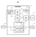
- FIG. 2 is a block diagram of an internal combustion engine control device 115.
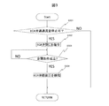
- FIG. 3 is a flowchart showing an operation of detecting the exhaust pressure of the internal combustion engine control device 115.
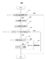
- 6 is a flowchart showing an operation of the internal combustion engine control device 115 in the second embodiment.
- 10 is a flowchart showing the operation of the internal combustion engine control device 115 in the third embodiment.
- FIG. 10 is a block diagram of an internal combustion engine control device 115 according to a fourth embodiment. 10 is a flowchart showing the operation of the internal combustion engine control device 115 in the fourth embodiment. 10 is a flowchart showing an operation of the internal combustion engine control device 115 in the fifth embodiment.
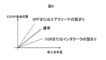
- 6 is a diagram showing the relationship between the flow rate of exhaust gas passing through an EGR valve 112 and the flow rate of fresh air sucked through the air cleaner 118.
- FIG. 1 is a configuration diagram of an internal combustion engine according
- FIG. 1 is a configuration diagram of an internal combustion engine according to the first embodiment.
- the internal combustion engine according to the first embodiment is provided with an exhaust gas recirculation (Exhaust Gas Recirculation) device.
- exhaust gas recirculation may be simply referred to as EGR.
- EGR exhaust Gas Recirculation
- an internal combustion engine 106 having an external EGR mechanism will be described in particular.
- the present invention is not limited to this, and the present invention can be similarly applied to other EGR mechanisms.
- the turbocharger 108 and the pre-catalyst 109 are installed in the piping of the exhaust path 119 of the internal combustion engine 106.
- the turbocharger 108 is composed of a turbine that rotates in response to an exhaust flow, a shaft that transmits the rotation of the turbine, and a compressor that takes in and compresses air using the torque of the turbine, and compresses using the exhaust flow. This is a supercharger that drives the machine to increase the density of the air taken in by the internal combustion engine 106.
- Exhaust gas from the internal combustion engine 106 is purified by reduction and oxidation in the pre-catalyst 109 and the main catalyst 113.
- Particulate matter that cannot be purified by the pre-catalyst 109 and the main catalyst 113 is purified by GPF 114 (Gasoline Particulate Filter).
- a part of the exhaust gas purified by the pre-catalyst 109 is taken into the EGR pipe 120 from the downstream of the pre-catalyst 109, cooled by the intercooler 110, and returned to the upstream of the turbocharger 108.
- the upstream of the turbocharger 108 is a portion where gas flows into the turbocharger 108.
- a part of the combustion gas generated in the cylinder 102 of the internal combustion engine 106 is recirculated to the intake pipe 116 via the EGR pipe 120 and mixed with the intake air newly sucked from the outside via the air cleaner 118.
- the air cleaner 118 removes dust contained in fresh air to be inhaled.
- the flow rate of the exhaust gas (EGR) recirculated through the EGR pipe 120 is determined by controlling the opening degree of the EGR valve 112. By controlling the EGR, it is possible to reduce the pumping loss while lowering the combustion temperature of the air-fuel mixture in the cylinder 102 to reduce the NOx emission amount.
- the internal combustion engine 106 is controlled by the internal combustion engine control device 115.
- the air flow sensor 101 detects the flow rate of fresh air that is newly sucked from the outside.
- a pressure sensor is attached between the turbocharger 108 and the cylinder 102 to detect the pressure of air in the intake pipe 104 that intakes the cylinder 102 or the intake chamber 104 downstream of the intake throttle valve 103.
- the flow rate of the mixed gas flowing from the intake pipe 116 to the cylinder 102 is controlled by a variable phase valve timing mechanism 117 that changes the opening degree of the intake throttle valve 103 and the opening / closing timing of the intake valve or the exhaust valve.
- the internal combustion engine control device 115 of the present embodiment controls the actuator so as to achieve the target EGR rate based on the detection value of the pressure sensor, the opening of the intake throttle valve 103, or the detection value of the air flow sensor 101. To do.
- the EGR rate refers to the ratio of fresh air to exhaust in the mixed gas flowing through the intake pipe 116.
- the internal combustion engine control device 115 detects a difference (differential pressure) between the pressure at the front stage and the pressure at the rear stage of the EGR valve 112 by a differential pressure sensor 111 attached so as to straddle the EGR valve 112, and based on that, the EGR valve 112 and The opening degree of the intake throttle valve 103 or the phase angle of the intake / exhaust valve is set by the variable phase valve timing mechanism 117, and the EGR rate of the mixed gas flowing in through the intercooler 110 is controlled. Further, the internal combustion engine control device 115 optimally controls the ignition timing of the spark plug 105 so as not to cause knocking and to maximize the output of the internal combustion engine 106.
- FIG. 2 is a block diagram of the internal combustion engine control device 115.
- the internal combustion engine control device 115 includes a detection unit 202, a travel distance detection unit 203, a diagnosis determination unit 205, a diagnosis execution unit 201, a diagnosis notification unit 207, and an actuator control unit 208.
- the actuator control unit 208 includes an EGR valve control unit 209 and a filter regeneration unit 210.
- the detection unit 202 detects clogging of the GPF 114, the air cleaner 118, or the intercooler 110 based on the output from each sensor 204.
- the sensor 204 includes a differential pressure sensor 111.
- Travel distance detection unit 203 detects the travel distance of the vehicle on which the internal combustion engine 106 is mounted.
- the diagnosis determination unit 205 acquires these detection results, and whether to permit learning of control parameters of each functional unit (for example, the EGR valve 112) included in the internal combustion engine 106 based on the detection results, or the GPF 114 Then, it is determined whether or not the diagnosis of the air cleaner 118 and the intercooler 110 is permitted.
- the diagnosis execution unit 201 performs the learning or diagnosis, and stores the result in the storage device 213.
- the diagnosis notification unit 207 notifies the driver that learning or diagnosis is being performed.
- the EGR valve control unit 209 reflects the detection result of each sensor 204 in the diagnosis for the EGR valve 112.
- Each sensor 204 is a differential pressure sensor 111, an air flow rate sensor 101, a rotation speed sensor 107, and other sensors (not shown) attached to the internal combustion engine 106, and can detect pressure, air flow rate, rotation speed, and the like.
- the filter regeneration unit 210 regenerates the GPF 114 based on the detection result of each sensor 204, and further updates the regeneration time as necessary.
- the diagnosis notification unit 207 obtains the state of whether or not learning or diagnosis is being performed from the diagnosis execution unit 201 and notifies the state to the outside of the vehicle via the notification unit 211. For example, a warning lamp provided in a driver room (not shown) is turned on.
- FIG. 3 is a flowchart showing an operation of detecting the exhaust pressure of the internal combustion engine control device 115.
- the internal combustion engine control device 115 repeatedly executes the flowchart of FIG. 3 in a predetermined program cycle.
- each step of FIG. 3 will be described.
- Step S301 The internal combustion engine control device 115 detects the rotational speed and the intake air amount of the internal combustion engine 106 by the rotational speed sensor 107 and the air flow rate sensor 101, and determines the operating state of the internal combustion engine 106 based on the rotational speed and the intake air amount. .
- the internal combustion engine control device 115 determines whether or not to allow the passage of exhaust gas through the EGR valve 112 to be stopped for diagnosis based on the information on the operating state by the diagnosis determination unit 205. If permitted, the process proceeds to step S302. If not permitted, the process returns to step S301.
- Step S302 When it is permitted to stop the flow rate of the EGR valve 112, the diagnosis execution unit 201 of the internal combustion engine control device 115 instructs the EGR valve control unit 209 to close the EGR valve 112 until it is fully closed.
- Step S303 The EGR valve control unit 209 detects whether or not the EGR valve 112 is closed based on the detection result of the opening degree of the EGR valve 112 from an opening degree sensor of the EGR valve 112 (not shown in the present embodiment). When the EGR valve 112 is closed, the process proceeds to S304, and when it is not closed, the process returns to step S303.
- Step S304 When it is detected that the EGR valve 112 is closed, the diagnosis execution unit 201 uses the differential pressure sensor 111 to calculate a difference in pressure before and after the EGR valve 112 (differential pressure). The diagnosis execution unit 201 determines the state of the internal combustion engine 106 based on the differential pressure (recirculation valve differential pressure) detected by the differential pressure sensor 111. The actuator control unit 208 determines the opening / closing and opening of the EGR valve 112 according to the operating state of the internal combustion engine 106. Thereby, control of the EGR valve 112 suitable for the operating state of the internal combustion engine 106 can be performed, and the utility of the control can be enhanced.
- the differential pressure sensor 111 is installed so as to straddle the exhaust gas recirculation valve (EGR valve) 112 in the exhaust gas recirculation path (EGR pipe) 120 after cooling, and the exhaust gas measured by the differential pressure sensor 111. Since the state of the internal combustion engine 106 including the exhaust path 119 is determined based on the differential pressure before and after the recirculation valve 112, the internal combustion engine including the high temperature portion is reduced while reducing the influence of the heat of the high temperature portion on the differential pressure sensor 111. The state of the engine 106 can be determined.
- the heat resistance performance required for the differential pressure sensor 111 is alleviated and the reliability is improved. Since the differential pressure sensor 111 can be used at a stable temperature, the measurement accuracy of the differential pressure is increased.
- the internal combustion engine control apparatus 115 is configured so that the static pressure upstream of the EGR valve 112 and the static pressure downstream of the EGR valve 112 are based on the differential pressure measured by the differential pressure sensor 111 with the EGR valve 112 closed. Both can be calculated.
- the upstream of the EGR valve 112 is a portion where gas flows into the EGR valve 112.
- the downstream of the EGR valve 112 is a portion where gas flows out from the EGR valve 112.
- both the intake pressure and the exhaust pressure of the internal combustion engine 106 can be known. Both intake pressure and exhaust pressure can be calculated without providing separate pressure sensors on the intake side and the exhaust side. Therefore, the utility of the control of the internal combustion engine 106 can be enhanced while suppressing the cost.
- the differential pressure detected by the differential pressure sensor 111 increases when the filter (GPF) 114 is clogged, and decreases when the cooler (intercooler) 110 is clogged. Can be detected individually.
- the internal combustion engine control device 115 can diagnose clogging of the GPF 114 in addition to the functions provided in the first embodiment.
- the internal combustion engine 106 of the second embodiment has the same configuration as that shown in FIG. 1, and the internal combustion engine control device 115 of the second embodiment has the same configuration as that shown in FIG.
- FIG. 4 is a flowchart showing the operation of the internal combustion engine control apparatus 115 according to the second embodiment. Steps S401 and S402 in FIG. 4 are the same as steps S301 and S402 in the first embodiment shown in FIG.
- Step S401 The internal combustion engine controller 115 detects the rotational speed and the intake air amount of the internal combustion engine 106 by using the rotational speed sensor 107 and the air flow rate sensor 101, and determines the operating state of the internal combustion engine 106 based on the rotational speed and the intake air amount. .
- the internal combustion engine control device 115 determines whether or not to allow the passage of exhaust gas through the EGR valve 112 to be stopped for diagnosis based on the information on the operating state by the diagnosis determination unit 205. If permitted, the process proceeds to step S402. If not permitted, the process returns to step S401.
- Step S402 When it is permitted to stop the flow rate of the EGR valve 112, the diagnosis execution unit 201 of the internal combustion engine control device 115 causes the EGR valve control unit 209 to instruct the EGR valve 112 to be closed before being fully closed. .
- Step S403 When it is detected that the EGR valve 112 is closed, the diagnosis execution unit 201 uses the differential pressure detected by the differential pressure sensor 111 to calculate the pressure at the front stage and the pressure at the rear stage of the EGR valve 112. Further, the diagnosis execution unit 201 calculates the pressure upstream (previous stage) of the GPF 114 based on the pressure upstream (previous stage) of the EGR valve 112. If the EGR valve 112 is fully closed, the pressure on the upstream side of the EGR valve 112 and the pressure on the upstream side (front stage) of the GPF 114 coincide. Further, the diagnosis execution unit 201 calculates the pressure downstream (rear stage) of the air cleaner 118 based on the pressure downstream (rear stage) of the EGR valve 112.
- the pressure at the rear stage of the EGR valve 112 matches the pressure at the downstream (rear stage) of the air cleaner 118.
- the upstream of the GPF 114 is a portion where gas flows into the GPF 114.
- the downstream of the GPF 114 is a portion where gas flows out of the GPF 114.
- the pressure on the upstream side of the GPF 114 is used in the subsequent processing.
- Step S404 The diagnosis determination unit 205 determines whether or not the pressure upstream of the GPF 114 calculated in step S403 is equal to or greater than a preset threshold value.
- the diagnosis determination unit 205 proceeds to step S405 when the pressure upstream of the GPF 114 is equal to or higher than the threshold value, and stops the diagnosis when the pressure is not equal to or higher than the threshold value.
- the clogging of the GPF 114 can be easily detected by comparing the upstream pressure of the EGR valve 112 (corresponding to the pressure upstream of the GPF 114) with a threshold value.
- Step S405 The diagnosis execution unit 201 determines the degree of clogging of the GPF 114 based on the pressure upstream of the GPF 114 calculated in step S403.
- the diagnosis execution unit 201 determines that the degree of clogging of the GPF 114 is large if the upstream pressure of the GPF 114 is equal to or higher than a preset reference value, and proceeds to step S406. That is, a large degree means that the pressure loss (pressure loss) in the GPF 114 is large. If the upstream pressure of the GPF 114 is smaller than the reference value, it is determined that the degree of clogging of the GPF 114 is small, and the process proceeds to step S407.
- Step S406 The process of step S406 is a countermeasure when the degree of clogging of the GPF 114 is large.
- the filter reproduction unit 210 performs reproduction of the GPF 114.
- the diagnosis execution unit 201 determines the degree of clogging of the GPF 114 based on the upstream pressure of the GPF 114 (or the upstream pressure of the EGR valve 112), and the filter regeneration unit 210 of the actuator control unit 208 determines the degree of clogging of the GPF 114. Accordingly, the regeneration time for purging the clogged GPF 114 may be changed. If there is a lot of clogging, the regeneration time may be lengthened, and if there is little clogging, the regeneration time may be shortened. Filter regeneration can be carried out for an appropriate time according to the degree of clogging of the GPF 114.
- Step S407 The process of step S407 is a countermeasure when the degree of clogging of the GPF 114 is small.
- the diagnosis execution unit 201 ends the diagnosis, returns the EGR valve 112 to the normal control by the EGR valve control unit 209, and sends the EGR valve control unit 209 to the EGR valve 112.
- the opening is controlled in the valve closing direction.
- the control in the valve closing direction is to reduce the target opening degree in the opening degree control of the EGR valve 112 by a predetermined amount compared to when the GPF 114 is not clogged.
- the degree of opening may be set according to the degree of clogging of the GPF 114. Since the EGR valve 112 is controlled in the valve closing direction in accordance with the clogging of the GPF 114, it is possible to control the exhaust gas to be recirculated.
- the internal combustion engine control device 115 detects clogging of the GPF 114 using the differential pressure sensor 111 attached so as to straddle the front and back of the EGR valve 112, and further The degree can be diagnosed. Thereby, it is not necessary to provide a differential pressure sensor across the GPF 114 for diagnosis of the GPF 114, and the utility of the control of the EGR valve 112 can be enhanced while reducing the cost.
- the differential pressure sensor straddling the GPF 114 directly detects high-temperature exhaust pressure, high heat resistance is required, but according to the configuration of the second embodiment, the differential pressure sensor 111 was cooled by the intercooler 110. Since the differential pressure of the exhaust is measured, the heat resistance requirement is relatively low.
- diagnosis execution unit 201 selects and uses an appropriate one from the two coping methods of regeneration of the GPF 114 and control of the valve closing direction of the EGR valve 112 according to the degree of the GPF 114 being clogged. Can do. Thereby, the frequency
- the filter regeneration unit 210 can change the regeneration time of the GPF 114 based on the degree of the GPF 114 clogging. Thereby, the utility of control of GPF114 can be improved, reducing a fuel consumption.
- the internal combustion engine control apparatus 115 can diagnose clogging of the air cleaner 118 in addition to the functions provided in the second embodiment.
- the internal combustion engine 106 of the third embodiment has the same configuration as that shown in FIG. 1, and the internal combustion engine control device 115 of the third embodiment has the same configuration as that shown in FIG.
- FIG. 5 is a flowchart showing the operation of the internal combustion engine control apparatus 115 according to the third embodiment. Steps S501 to S503 in FIG. 5 are the same as steps S401 to S403 shown in FIG. Steps S504 to S507 are processes unique to the third embodiment.
- Step S503 In step S503, as in step S403, the diagnosis execution unit 201 calculates the pressure on the upstream side (front stage) of the GPF 114 and the pressure on the downstream side (back stage) of the air cleaner 118. In the second embodiment, the pressure on the upstream side of the GPF 114 is used, but in this embodiment, the pressure on the downstream side (rear stage) of the air cleaner 118 is used in the subsequent processing.
- Step S504 The diagnosis determination unit 205 determines whether or not the pressure downstream of the air cleaner 118 calculated in step S503 is equal to or less than a preset threshold value.
- the diagnosis determination unit 205 proceeds to step S505 when the pressure downstream of the air cleaner 118 is equal to or lower than the threshold value, and stops the diagnosis when not lower than the set value.
- the clogging of the air cleaner 118 can be easily detected by comparing the downstream pressure of the EGR valve 112 (corresponding to the pressure downstream of the air cleaner 118) with a threshold value.
- Step S505 The diagnosis execution unit 201 determines the degree of blockage of the air cleaner 118 based on the pressure downstream of the air cleaner 118 calculated in step S503. If the downstream pressure of the air cleaner 118 is equal to or less than a preset reference value, the diagnosis execution unit 201 determines that the degree of clogging of the air cleaner 118 is large, and proceeds to step S506. That is, a large degree means that the pressure loss (pressure loss) in the air cleaner 118 is large. If the downstream pressure of the air cleaner 118 is greater than the reference value, it is determined that the degree of clogging of the air cleaner 118 is small, and the process proceeds to step S507.
- Step S506 The process of step S506 is a countermeasure when the degree of clogging of the air cleaner 118 is large.
- the diagnosis notification unit 207 presents a message prompting the user to replace the air cleaner 118 via the notification unit 211 to the driver.
- the notification unit 211 presents the message to the driver visually or audibly or both.
- Visual presentation methods include lighting a warning lamp or displaying on a display screen. As an auditory presentation method, there is a warning sound output or a sound output.
- Step S507 The process of step S507 is a countermeasure when the degree of clogging of the air cleaner 118 is small.
- the diagnosis execution unit 201 ends the diagnosis, returns the EGR valve 112 to normal control by the EGR valve control unit 209, and sends the EGR valve control unit 209 to the EGR valve 112. Is controlled in the valve closing direction. Since the EGR valve 112 is controlled in the valve closing direction in accordance with the clogging of the air cleaner 118, it is possible to control so as to maintain the ratio (EGR rate) between fresh air that has passed through the air cleaner 118 and recirculated exhaust gas.
- EGR rate ratio
- the internal combustion engine control apparatus 115 detects the clogging of the air cleaner 118 using the differential pressure sensor 111 attached so as to straddle the front and rear of the EGR valve 112, and further The degree can be diagnosed. Thereby, it is not necessary to provide a differential pressure sensor across the air cleaner 118 for diagnosis of the air cleaner 118, and the utility of control of the EGR valve 112 can be enhanced while reducing costs.
- the diagnosis execution unit 201 selects an appropriate one from the two coping methods, that is, replacement of the air cleaner 118 and control of the valve closing direction of the EGR valve 112 according to the degree of clogging of the air cleaner 118. Can be used. Thereby, the frequency
- the internal combustion engine control device 115 according to the sixth embodiment can diagnose clogging of the intercooler in addition to the functions provided in the second embodiment.
- the internal combustion engine 106 of the fourth embodiment has the same configuration as that shown in FIG.
- FIG. 6 is a block diagram of the internal combustion engine control apparatus 115 according to the fourth embodiment.
- the internal combustion engine control device 115 of the fourth embodiment is different from that of the first embodiment shown in FIG. 1 in that the actuator control unit 208 includes an intercooler temperature raising unit 214.
- FIG. 7 is a flowchart showing the operation of the internal combustion engine control apparatus 115 according to the fourth embodiment. Steps S601 and S602 in the fourth embodiment are the same as steps S401 and S402 in the first embodiment shown in FIG.
- Step S603 When it is detected that the EGR valve 112 is closed, the diagnosis execution unit 201 uses the differential pressure sensor 111 to calculate a difference (differential pressure) between the pressure at the front stage and the pressure at the rear stage of the EGR valve 112. Further, the diagnosis execution unit 201 calculates the upstream pressure of the GPF 114 and the downstream pressure of the air cleaner 118 based on the differential pressure. The storage device 213 records the pressure upstream of the GPF 114 and the pressure downstream of the air cleaner 118.
- Step S604 The internal combustion engine control device 115 causes the diagnosis determination unit 205 to open the EGR valve 112 and control the intake throttle valve 103 so that the air flow rate detected by the air flow rate sensor 101 is constant.
- Step S605 The diagnosis determination unit 205 determines whether or not the air flow rate detected by the air flow rate sensor 101 is constant. The diagnosis determining unit 205 proceeds to step S606 if the air flow rate is constant, and therefore proceeds to step S606. If not, the diagnosis determining unit 205 returns to step S604 because the intercooler 110 cannot be diagnosed. .
- the diagnosis executing unit 201 causes the EGR valve control unit 209 to close the EGR valve 112 and determines the state of the internal combustion engine 106 based on the differential pressure detected by the differential pressure sensor 111. Will be judged. Since the EGR valve 112 is closed when the diagnosis is determined, the EGR valve 112 can be closed in the diagnosis and the state of the internal combustion engine 106 can be acquired by the differential pressure sensor 111.
- Step S606 The diagnosis execution unit 201 measures the upstream pressure of the EGR valve 112, that is, the downstream pressure of the intercooler 110, using the differential pressure sensor 111 while the air flow rate detected by the air flow rate sensor 101 is constant. Furthermore, the diagnosis execution unit 201 calculates the pressure loss of the intercooler 110 by subtracting the pressure upstream of the GPF 114 measured in step S603 from the downstream pressure of the intercooler 110.
- Step S607 The diagnosis execution unit 201 determines whether there is a pressure loss of the intercooler 110 calculated in step S606. The diagnosis execution unit 201 proceeds to step S608 when the pressure loss is not zero, that is, when there is a pressure loss, and ends the diagnosis when the pressure loss is zero, that is, when there is no pressure loss.
- the differential pressure across the EGR valve 112 with the EGR valve 112 opened is lower than the differential pressure across the EGR valve 112 detected with the EGR valve 112 closed. In this case, it is possible to determine that pressure loss has occurred due to clogging of the intercooler 110. The clogging of the intercooler 110 can be easily determined based on whether or not the differential pressure between the EGR valve 112 in the opened state and the closed EGR valve 112 is equal.
- Step S608 The diagnosis execution unit 201 determines the degree of blocking of the intercooler 110 based on the pressure loss of the intercooler 110 calculated in step S606. If the pressure loss of the intercooler 110 is equal to or greater than a preset reference value, the diagnosis execution unit 201 determines that the degree of clogging of the intercooler 110 is large, and proceeds to step S609. On the other hand, if the pressure loss of the intercooler 110 is smaller than the reference value, the diagnosis execution unit 201 determines that the degree of clogging of the intercooler 110 is small, and proceeds to step S610.
- Step S609 When it is determined that the degree of clogging of the intercooler 110 is large, the intercooler temperature raising unit 214 heats the circulating water of the intercooler 110 to raise the temperature, thereby reducing the cooling capacity of the intercooler 110. Thereby, it is possible to suppress the exhaust gas from being excessively cooled by the clogging of the intercooler 110.
- Step S610 When it is determined that the degree of clogging of the intercooler 110 is small, the diagnosis execution unit 201 returns the EGR valve 112 to normal control by the EGR valve control unit 209, and the EGR valve control unit 209 opens the EGR valve 112. Control in the direction.
- the control in the valve opening direction is to increase the target opening in the opening control of the EGR valve 112 by a predetermined amount compared to when the intercooler 110 is not clogged.
- the degree of opening may be set according to the degree of clogging of the intercooler 110.
- the EGR valve 112 is controlled in the valve opening direction accordingly. Therefore, the reduction of the recirculated exhaust gas due to the blockage of the intercooler 110 is suppressed, and the recirculated exhaust gas amount is controlled. be able to.
- the internal combustion engine control device 115 detects the clogging of the intercooler 110 using the differential pressure sensor 111 provided across the front and rear of the EGR valve 112, and further the intercooler 110.
- the degree of clogging can be diagnosed. Thereby, it is not necessary to provide a differential pressure sensor across the intercooler 110 for diagnosis of the intercooler 110, and the utility of the control of the EGR valve 112 can be enhanced while reducing costs.
- the diagnosis execution unit 201 selects an appropriate one from the two coping methods, that is, the temperature rise of the intercooler 110 and the control of the valve opening direction of the EGR valve 112, according to the degree of clogging of the intercooler 110. Can be used. Thereby, the frequency
- the differential pressure sensor When the differential pressure sensor is installed so as to straddle the intercooler 110 as in the prior art, the pressure difference detected by the differential pressure sensor increases regardless of which of the GPF 114 and the intercooler 110 is clogged. Therefore, when the pressure difference detected by the differential pressure sensor has increased, it has not been possible to determine which is clogged. Further, when both of them are clogged at the same time, it is difficult to detect the clogging because the clogging with the smaller clogging is hidden by the influence of the clogging with the larger clogging. That is, when both the GPF 114 and the intercooler 110 are clogged, it is difficult to detect the clogging of a device with a small degree.
- the fifth embodiment is an example in which diagnosis is performed when the travel distance becomes a certain distance or more.
- the object of diagnosis is the same as in the first to fourth embodiments, and is, for example, a GPF, an air cleaner, or an intercooler.
- the internal combustion engine 106 of the fifth embodiment has the same configuration as that shown in FIG. 1, and the internal combustion engine control device 115 of the fifth embodiment has the same configuration as that shown in FIG.
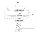
- FIG. 8 is a flowchart showing the operation of the internal combustion engine control apparatus 115 according to the fifth embodiment. In the fifth embodiment, it is determined in step S701 to step S703 shown in FIG. When performing diagnosis, the EGR valve 112 is closed in step S703.
- the processing after closing the EGR valve 112 is the same as that in the first to fourth embodiments.
- the processing in steps S303 to S304 shown in FIG. 3 is executed.
- the processing in steps S403 to S407 shown in FIG. 4 is executed.
- the processing in steps S503 to S507 shown in FIG. 5 is executed.
- steps S603 to S610 shown in FIG. 7 are executed.
- Step S701 The diagnosis determination unit 205 acquires information on the accumulated travel distance measured by the odometer of the vehicle on which the internal combustion engine 106 is mounted, and determines whether the accumulated travel distance is equal to or greater than a preset diagnosis execution reference distance. If the accumulated travel distance is equal to or greater than the diagnosis execution reference distance, diagnosis determination unit 205 determines to execute diagnosis of GPF 114, air cleaner 118, and intercooler 110, and the process proceeds to step S703. If the accumulated travel distance does not satisfy the diagnosis execution reference distance, the diagnosis determination unit 205 proceeds to step S702.
- FIG. 9 is a diagram showing the relationship between the flow rate of exhaust gas passing through the EGR valve 112 and the flow rate of fresh air drawn through the air cleaner 118.
- the flow rate of fresh air drawn through the air cleaner 118 is detected by the air flow rate sensor 101.
- the ratio of the flow rate of the exhaust gas passing through the EGR valve 112 to the flow rate of fresh air sucked through the air cleaner 118 increases as compared with the normal time.
- the ratio of the flow rate of the exhaust gas passing through the EGR valve 112 to the flow rate of fresh air sucked through the air cleaner 118 is reduced as compared with the normal time when the intercooler 110 is used.
- the influence of the flow rate error of the exhaust gas passing through the EGR valve 112 depends on the flow rate of fresh air sucked through the air cleaner 118. If the flow rate of fresh air sucked from the outside through the air cleaner 118 increases, the influence of the flow rate error of the EGR valve 112 is reduced and the accuracy of diagnosis is increased.
- the diagnosis determination unit 205 determines whether to close the EGR valve 112, that is, whether to permit diagnosis based on the air flow rate detected by the air flow rate sensor 101. If the air flow rate detected by the air flow rate sensor 101 is equal to or higher than a preset diagnosis execution reference flow rate, the diagnosis determination unit 205 determines to execute the diagnosis of the GPF 114, the air cleaner 118, or the intercooler 110, and the step The process proceeds to S703. If the air flow rate detected by the air flow rate sensor 101 does not satisfy the diagnosis execution reference flow rate, the diagnosis determination unit 205 ends the diagnosis.
- the internal combustion engine control device 115 is retarded from the ignition timing during normal operation.
- the ignition timing may be used. By retarding the ignition timing, knocking of the internal combustion engine 106 can be suppressed.
- the internal combustion engine control apparatus 115 performs a clogging diagnosis of the GPF 114, the air cleaner 118, or the intercooler 110 when the accumulated traveling distance reaches a predetermined distance. Thereby, the normal performance of the internal combustion engine 106 can be ensured.
- the internal combustion engine control apparatus 115 performs diagnosis when the flow rate of air newly sucked from the outside through the air cleaner 118 exceeds a predetermined amount.
- the diagnosis accuracy can be improved by executing the diagnosis when the air flow rate from the outside is large.
- the internal combustion engine control apparatus 115 can suppress knocking of the internal combustion engine 106 by retarding the ignition timing when the diagnosis is performed in a state where the flow rate of air sucked from the outside is large.
- the internal combustion engine control apparatus 115 diagnoses the presence / absence and degree of clogging of the GPF 114 using the differential pressure sensor 111 provided so as to straddle the EGR valve 112.
- a second differential pressure sensor may be provided so as to straddle the front and rear of the GPF 114.
- the second differential pressure sensor measures the difference (differential pressure) between the upstream (front) and downstream (rear) pressure of the GPF 114, and the presence or absence of the GPF 114 can be determined from the differential pressure.
- the diagnosis execution unit 201 uses the detection value of the first differential pressure sensor 111 provided in the EGR valve 112 and the detection value of the second differential pressure sensor, and uses the first differential pressure sensor.
- the normality of 111 and the second differential pressure sensor can be examined. If the degree of clogging based on the detection value of the first differential pressure sensor 111 and the degree of clogging based on the detection value of the second differential pressure sensor are within a certain range, the first differential pressure sensor 111 and the second differential pressure sensor 111 It can be determined that the differential pressure sensor is normal.
- the first differential pressure sensor 111 and the second differential pressure sensor 111 It can be estimated that at least one of the differential pressure sensors is abnormal.
- the internal combustion engine 106 of the above-described embodiment is assumed to be a spark ignition internal combustion engine including the ignition plug 105, a compression ignition internal combustion engine (for example, a diesel engine or a premixed compression ignition engine is used). Thing).
- a compression ignition internal combustion engine for example, a diesel engine or a premixed compression ignition engine is used. Thing).
- each of the above-described configurations, functions, processing units, processing means, and the like may be realized by hardware by designing a part or all of them with, for example, an integrated circuit.
- Each of the above-described configurations, functions, and the like may be realized by software by interpreting and executing a program that realizes each function by the processor.
- Information such as programs, tables, and files for realizing each function can be stored in a recording device such as a memory, a hard disk, an SSD (Solid State Drive), or a recording medium such as an IC card, an SD card, or a DVD.
- SYMBOLS 101 Air flow sensor, 102 ... Cylinder, 103 ... Intake throttle valve, 104 ... Intake chamber, 106 ... Internal combustion engine, 107 ... Revolution sensor, 108 ... Turbocharger, 109 ... Pre-catalyst, 110 ... Intercooler, 111 ... Differential pressure Sensor 112, EGR valve 113, main catalyst 114, GPF 115, internal combustion engine controller 116 116 intake pipe 117 117 variable phase valve timing mechanism 118 air cleaner 119 exhaust path 120 EGR pipe DESCRIPTION OF SYMBOLS 201 ... Diagnosis execution part, 202 ... Detection part, 203 ... Travel distance detection part, 204 ... Sensor, 205 ...
- Diagnosis determination part 207 ... Diagnosis notification part, 208 ... Actuator control part, 209 ... EGR valve control part, 210 ... Filter Reproduction unit 211 ... notification unit 213 ... storage device 214 ... intercool Temperature-raising section
Landscapes
- Engineering & Computer Science (AREA)
- Chemical & Material Sciences (AREA)
- Combustion & Propulsion (AREA)
- Mechanical Engineering (AREA)
- General Engineering & Computer Science (AREA)
- Signal Processing (AREA)
- Toxicology (AREA)
- Chemical Kinetics & Catalysis (AREA)
- Health & Medical Sciences (AREA)
- Physics & Mathematics (AREA)
- Fluid Mechanics (AREA)
- Analytical Chemistry (AREA)
- Exhaust-Gas Circulating Devices (AREA)
- Electrical Control Of Ignition Timing (AREA)
- Exhaust Gas After Treatment (AREA)
- Output Control And Ontrol Of Special Type Engine (AREA)
- Processes For Solid Components From Exhaust (AREA)
- Combined Controls Of Internal Combustion Engines (AREA)
Abstract
高い信頼性と高い精度で内燃機関の状態を検出することを可能にする技術を提供する。 気筒からの排気の一部を分離し、冷却器で冷却し、排気再循環弁を介して吸気に混合して前記気筒に供給する構成の内燃機関を制御する内燃機関制御装置であって、前記排気再循環弁を跨いで設置され、前記排気再循環弁の前段の圧力と後段の圧力の差を再循環弁差圧として検知する第1差圧センサと、前記排気再循環弁を制御する制御部と、前記制御部に前記排気再循環弁を閉じさせ、その状態で前記第1差圧センサにて検知された再循環弁差圧に基づいて前記内燃機関の状態を判断する診断実施部と、を有している。
Description
本発明は内燃機関を制御する技術に関する。
特許文献1には「本発明の内燃機関の制御装置は、低圧EGR制御弁の上下流間の圧力差を差圧検出装置で検出し、それに基づいてEGR制御弁の作動および吸気絞り弁の作動を制御する。差圧計測装置は、吸気絞り弁が非作動全開状態のとき、吸気絞り弁とEGR制御弁との間の第1領域部とEGR制御弁より上流の第2領域部とにおける圧力差を検出し、吸気絞り弁が作動状態のとき、第2領域部と第2領域部より下流かつEGR制御弁より上流の第3領域部とにおける圧力差に基づいてEGR制御弁の上下流間の圧力差を検出する」と記載されている。これにより、吸気側圧力を検出することが可能になっていると考えられる。
特許文献1記載の技術においては、EGRバルブ上流のインタクーラを跨ぐように差圧センサを取り付け、その差圧センサで検出される圧力差に基づいて吸気側の圧力を計算する。インタクーラは、その上流が高温であるため、差圧センサの信頼性が問題となり、差圧センサには高い耐熱性能が要求される。また、特許文献1では、吸気側の圧力を直接測るではなく、物理モデルを利用して吸気側の圧力を推定する。したがって、物理モデルの精度によって圧力検知の精度が不十分になる可能性がある。
本発明の目的は、高い信頼性と高い精度で内燃機関の状態を検出することを可能にする技術を提供することである。
本発明のひとつの態様による内燃機関制御装置は、気筒からの排気の一部を分離し、冷却器で冷却し、排気再循環弁を介して吸気に混合して前記気筒に供給する構成の内燃機関を制御する内燃機関制御装置であって、前記排気再循環弁を跨いで設置され、前記排気再循環弁の前段の圧力と後段の圧力の差を再循環弁差圧として検知する第1差圧センサと、前記排気再循環弁を制御する制御部と、前記制御部に前記排気再循環弁を閉じさせ、その状態で前記第1差圧センサにて検知された再循環弁差圧に基づいて前記内燃機関の状態を判断する診断実施部と、を有している。
本発明によれば、第1差圧センサを冷却後の排気再循環経路に排気再循環弁を跨ぐように設置し、第1差圧センサで測定される排気再循環弁の前後の差圧に基づいて、排気経路を含む経路の状態を判断するので、第1差圧センサへの高温部分の熱の影響を低減しつつ、高温部分を含む経路の状態を判断することができる。
<実施形態1>
図1は、実施形態1に係る内燃機関の構成図である。実施形態1に係る内燃機関は排気再循環(Exhaust Gas Recirculation)装置を備えている。排気再循環を以下では単にEGRと呼ぶこともある。本実施形態では、特に外部EGR機構を備えた内燃機関106について説明する。ただし、本発明がこれに限定されるわけではなく、他のEGR機構であっても本発明を同様に適用できる。
図1は、実施形態1に係る内燃機関の構成図である。実施形態1に係る内燃機関は排気再循環(Exhaust Gas Recirculation)装置を備えている。排気再循環を以下では単にEGRと呼ぶこともある。本実施形態では、特に外部EGR機構を備えた内燃機関106について説明する。ただし、本発明がこれに限定されるわけではなく、他のEGR機構であっても本発明を同様に適用できる。
内燃機関106の排気経路119の配管にターボチャージャ108とプリ触媒109が設置されている。ターボチャージャ108は排気の流れを受けて回転するタービンと、タービンの回転を伝達するシャフト、タービンのトルクを利用して空気を取り込んで圧縮する圧縮機で構成され、排気の流れを利用して圧縮機を駆動して内燃機関106が吸入する空気の密度を高くする過給機である。
内燃機関106からの排気はプリ触媒109とメイン触媒113において還元および酸化によって浄化される。プリ触媒109およびメイン触媒113で浄化できない粒子状物質はGPF114(Gasoline Particulate Filter)によって浄化される。
プリ触媒109により浄化された排気の一部はプリ触媒109の下流からEGR配管120に取り込まれ、インタクーラ110で冷却されターボチャージャ108の上流に戻される。ターボチャージャ108の上流というのは、気体がターボチャージャ108へ流入する部分である。内燃機関106の気筒102内で発生する燃焼ガスの一部がEGR配管120を経由して吸気配管116に還流させて、エアクリーナ118を介して外部から新たに吸入される吸気に混合される。
エアクリーナ118は、吸入する新気に含まれる塵埃などを除去する。なお、EGR配管120で還流させる排気(EGR)の流量はEGRバルブ112の開度を制御することにより決定される。このEGRの制御により気筒102での混合気の燃焼温度を低下させてNOxの排出量を削減しつつ、ポンピングロスの低減を図ることができる。
内燃機関106は内燃機関制御装置115により制御される。空気流量センサ101は外部から新たに吸入される新気の流量を検出する。また図示していないが、ターボチャージャ108と気筒102の間には圧力センサが取り付けられ、気筒102へ吸気する吸気配管116あるいは吸気スロットルバルブ103下流の吸気チャンバ104管内の空気の圧力を検知する。吸気配管116から気筒102に流れる混合ガスの流量は吸気スロットルバルブ103の開度、吸気バルブ又は排気バルブの開閉タイミングを変化させる可変位相バルブタイミング機構117により制御される。
本実施形態の内燃機関制御装置115は上記した圧力センサの検出値、吸気スロットルバルブ103の開度、あるいは空気流量センサ101の検出値に基づいて、目標のEGR率を実現するようにアクチュエータを制御する。
なお、本実施形態においてEGR率は、吸気配管116を流れる混合ガスのうち、新気と排気の割合のことをいう。そして内燃機関制御装置115は、EGRバルブ112を跨ぐように取り付けられる差圧センサ111によりEGRバルブ112の前段の圧力と後段の圧力の差分(差圧)を検知し、それに基づいてEGRバルブ112および吸気スロットルバルブ103の開度、あるいは可変位相バルブタイミング機構117により吸排バルブの位相角度を設定し、インタクーラ110を介して流入する混合ガスのEGR率を制御する。また、内燃機関制御装置115はノッキングを発生させない、且つ内燃機関106の出力を最大化するように点火プラグ105の点火タイミングを最適に制御する。
図2は、内燃機関制御装置115のブロック図である。内燃機関制御装置115は、つまり検出部202、走行距離検出部203、診断決定部205、診断実施部201、診断報知部207、およびアクチュエータ制御部208を備える。アクチュエータ制御部208は、EGRバルブ制御部209およびフィルタ再生部210を備える。
つまり検出部202は、各センサ204からの出力に基づき、GPF114、エアクリーナ118、あるいはインタクーラ110の詰まりを検知する。センサ204には差圧センサ111が含まれる。
走行距離検出部203は、内燃機関106を載せた車両の走行距離を検出する。診断決定部205は、これら検出結果を取得し、その検出結果に基づいて、内燃機関106が備える各機能部(例えばEGRバルブ112)の制御パラメータを学習することを許可するか否か、またはGPF114、エアクリーナ118とインタクーラ110の診断を実施することを許可するか否かを決定する。診断実施部201は、上記学習または診断を実施し、その結果を記憶装置213に格納する。診断報知部207は、学習または診断を実施していることをドライバーに対して報知する。
EGRバルブ制御部209は、各センサ204による検出結果を、EGRバルブ112に対する診断において反映する。各センサ204は内燃機関106に取り付けられた差圧センサ111、空気流量センサ101、回転数センサ107とその他図示していないセンサであり、圧力、空気流量、回転数、などを検出することができる。フィルタ再生部210は、各センサ204による検出結果に基づき、GPF114の再生を実施し、さらに必要に応じて再生時間を更新する。
診断報知部207は、診断実施部201から学習または診断を実施しているか否かの状態を取得し、その状態を報知部211経由で車外に対して報知する。例えば、図示しないドライバー室が備える警告ランプを点灯させる。
図3は、内燃機関制御装置115の排気圧を検出する動作を示すフローチャートである。内燃機関制御装置115は、図3のフローチャートを所定のプログラムサイクルで繰り返し実行する。以下図3の各ステップについて説明する。
・ステップS301
内燃機関制御装置115は、回転数センサ107と空気流量センサ101により内燃機関106の回転数と吸入空気量を検出し、それら回転数および吸入空気量に基づいて内燃機関106の運転状態を判断する。内燃機関制御装置115は、診断決定部205により、運転状態の情報に基づいて、診断のためにEGRバルブ112の排気の通過を停止することを許可するか否かを判断する。許可する場合はステップS302へ進み、許可しない場合ステップS301に戻る。
内燃機関制御装置115は、回転数センサ107と空気流量センサ101により内燃機関106の回転数と吸入空気量を検出し、それら回転数および吸入空気量に基づいて内燃機関106の運転状態を判断する。内燃機関制御装置115は、診断決定部205により、運転状態の情報に基づいて、診断のためにEGRバルブ112の排気の通過を停止することを許可するか否かを判断する。許可する場合はステップS302へ進み、許可しない場合ステップS301に戻る。
・ステップS302
EGRバルブ112の通過流量を停止することが許可される場合に、内燃機関制御装置115の診断実施部201は、EGRバルブ制御部209に、EGRバルブ112へ、全閉まで閉じることを指令させる。
EGRバルブ112の通過流量を停止することが許可される場合に、内燃機関制御装置115の診断実施部201は、EGRバルブ制御部209に、EGRバルブ112へ、全閉まで閉じることを指令させる。
・ステップS303
EGRバルブ制御部209は、本実施形態に図示しないEGRバルブ112の開度センサからEGRバルブ112の開度の検出結果に基づいて、EGRバルブ112を閉じたか否かを検出する。EGRバルブ112を閉じた場合S304へ進み、閉じてない場合はステップS303に戻る。
EGRバルブ制御部209は、本実施形態に図示しないEGRバルブ112の開度センサからEGRバルブ112の開度の検出結果に基づいて、EGRバルブ112を閉じたか否かを検出する。EGRバルブ112を閉じた場合S304へ進み、閉じてない場合はステップS303に戻る。
・ステップS304
EGRバルブ112を閉じたことが検出された場合に、診断実施部201は、差圧センサ111を用いてEGRバルブ112の前後の圧力の差分(差圧)を算出する。診断実施部201は、差圧センサ111にて検知された差圧(再循環弁差圧)に基づいて内燃機関106の状態を判断する。アクチュエータ制御部208は、内燃機関106の運転状態に応じて、EGRバルブ112の開閉および開度を決定する。これにより、内燃機関106の運転状態に適したEGRバルブ112の制御を実施することができ、制御の効用を高めることができる。
EGRバルブ112を閉じたことが検出された場合に、診断実施部201は、差圧センサ111を用いてEGRバルブ112の前後の圧力の差分(差圧)を算出する。診断実施部201は、差圧センサ111にて検知された差圧(再循環弁差圧)に基づいて内燃機関106の状態を判断する。アクチュエータ制御部208は、内燃機関106の運転状態に応じて、EGRバルブ112の開閉および開度を決定する。これにより、内燃機関106の運転状態に適したEGRバルブ112の制御を実施することができ、制御の効用を高めることができる。
本実施形態によれば、差圧センサ111を冷却後の排気再循環経路(EGR配管)120に排気再循環弁(EGRバルブ)112を跨ぐように設置し、差圧センサ111で測定される排気再循環弁112の前後の差圧に基づいて、排気経路119を含む内燃機関106の状態を判断するので、差圧センサ111への高温部分の熱の影響を低減しつつ、高温部分を含む内燃機関106の状態を判断することができる。
また、本実施形態によれば、差圧センサ111に要求される耐熱性能が緩和され、信頼性が高まる。差圧センサ111を安定した温度で用いることができるので、差圧の測定精度が高まる。
また、本実施形態1に係る内燃機関制御装置115は、EGRバルブ112を閉じた状態で差圧センサ111で計測される差圧に基づいて、EGRバルブ112上流の静圧と下流の静圧の両方を算出することができる。EGRバルブ112の上流というのはEGRバルブ112に気体が流入する部分である。EGRバルブ112の下流というのはEGRバルブ112から気体が流出する部分である。
これにより、内燃機関106の吸気圧力と排気圧力の両方を知ることができる。吸気側と排気側にそれぞれ別の圧力センサを設けなくでも吸気圧力と排気圧力の両方を算出することができる。したがって、コストを抑制しつつ、内燃機関106の制御の効用を高めることができる。
また、本実施形態によれば、差圧センサ111で検知される差圧はフィルタ(GPF)114が詰まると上昇し、冷却器(インタクーラ)110が詰まると低下するので、フィルタ114と冷却器110の詰まりを個別に検出することができる。
<実施形態2>
実施形態2の内燃機関制御装置115は、実施形態1のものが備える機能に加えて、GPF114のつまりを診断することができる。実施形態2の内燃機関106は図1に示したものと同様の構成を有し、実施形態2の内燃機関制御装置115は図2に示したものと同様の構成を有する。
実施形態2の内燃機関制御装置115は、実施形態1のものが備える機能に加えて、GPF114のつまりを診断することができる。実施形態2の内燃機関106は図1に示したものと同様の構成を有し、実施形態2の内燃機関制御装置115は図2に示したものと同様の構成を有する。
図4は、実施形態2における内燃機関制御装置115の動作を示すフローチャートである。図4におけるステップS401およびステップS402は、図3に示した実施形態1のステップS301およびステップS402と同様である。
・ステップS401
内燃機関制御装置115は、回転数センサ107と空気流量センサ101により内燃機関106の回転数と吸入空気量を検出し、それら回転数と吸入空気量に基づいて内燃機関106の運転状態を判断する。内燃機関制御装置115は、診断決定部205により、運転状態の情報に基づいて、診断のためにEGRバルブ112の排気の通過を停止することを許可するか否かを判断する。許可する場合はステップS402へ進み、許可しない場合ステップS401に戻る。
内燃機関制御装置115は、回転数センサ107と空気流量センサ101により内燃機関106の回転数と吸入空気量を検出し、それら回転数と吸入空気量に基づいて内燃機関106の運転状態を判断する。内燃機関制御装置115は、診断決定部205により、運転状態の情報に基づいて、診断のためにEGRバルブ112の排気の通過を停止することを許可するか否かを判断する。許可する場合はステップS402へ進み、許可しない場合ステップS401に戻る。
・ステップS402
EGRバルブ112の通過流量を停止することが許可される場合に、内燃機関制御装置115の診断実施部201は、EGRバルブ制御部209に、EGRバルブ112へ、全閉までに閉じることを指令させる。
EGRバルブ112の通過流量を停止することが許可される場合に、内燃機関制御装置115の診断実施部201は、EGRバルブ制御部209に、EGRバルブ112へ、全閉までに閉じることを指令させる。
・ステップS403
EGRバルブ112を閉じたことを検出される場合に、診断実施部201は、差圧センサ111で検知される差圧を用いてEGRバルブ112の前段の圧力と後段の圧力を算出する。更に、診断実施部201は、EGRバルブ112の上流(前段)の圧力に基づいて、GPF114の上流(前段)の圧力を算出する。EGRバルブ112が全閉であれば、EGRバルブ112の前段の圧力と、GPF114の上流(前段)の圧力は一致する。また、診断実施部201は、EGRバルブ112の下流(後段)の圧力に基づいて、エアクリーナ118の下流(後段)の圧力を算出する。EGRバルブ112が全閉であれば、EGRバルブ112の後段の圧力と、エアクリーナ118の下流(後段)の圧力は一致する。GPF114の上流というのはGPF114に気体が流入する部分である。GPF114の下流というのはGPF114から気体が流出する部分である。本実施形態では、これ以降の処理でGPF114の上流側の圧力が用いられる。
EGRバルブ112を閉じたことを検出される場合に、診断実施部201は、差圧センサ111で検知される差圧を用いてEGRバルブ112の前段の圧力と後段の圧力を算出する。更に、診断実施部201は、EGRバルブ112の上流(前段)の圧力に基づいて、GPF114の上流(前段)の圧力を算出する。EGRバルブ112が全閉であれば、EGRバルブ112の前段の圧力と、GPF114の上流(前段)の圧力は一致する。また、診断実施部201は、EGRバルブ112の下流(後段)の圧力に基づいて、エアクリーナ118の下流(後段)の圧力を算出する。EGRバルブ112が全閉であれば、EGRバルブ112の後段の圧力と、エアクリーナ118の下流(後段)の圧力は一致する。GPF114の上流というのはGPF114に気体が流入する部分である。GPF114の下流というのはGPF114から気体が流出する部分である。本実施形態では、これ以降の処理でGPF114の上流側の圧力が用いられる。
・ステップS404
診断決定部205は、ステップS403により算出されたGPF114の上流の圧力が予め設定された閾値以上であるか否か判断する。診断決定部205は、GPF114の上流の圧力が閾値以上となる場合は、ステップS405へ進み、閾値以上とならない場合は診断を中止する。ここではGPF114のつまりがあるか否かを判定している。GPF114のつまりがある場合には、ステップS405に進んで、GPF114のつまりの対処する。GPF114のつまりが無い場合には、対処が不要なので処理を終了する。EGRバルブ112の上流圧力(GPF114の上流の圧力に相当)を閾値と比較することによりGPF114の詰まりを容易に検出することができる。
診断決定部205は、ステップS403により算出されたGPF114の上流の圧力が予め設定された閾値以上であるか否か判断する。診断決定部205は、GPF114の上流の圧力が閾値以上となる場合は、ステップS405へ進み、閾値以上とならない場合は診断を中止する。ここではGPF114のつまりがあるか否かを判定している。GPF114のつまりがある場合には、ステップS405に進んで、GPF114のつまりの対処する。GPF114のつまりが無い場合には、対処が不要なので処理を終了する。EGRバルブ112の上流圧力(GPF114の上流の圧力に相当)を閾値と比較することによりGPF114の詰まりを容易に検出することができる。
・ステップS405
診断実施部201は、ステップS403により算出されたGPF114の上流の圧力に基づいてGPF114のつまりの程度を判断する。診断実施部201は、GPF114の上流圧力が予め設定された基準値以上であればGPF114のつまりの程度が大きいと判断し、ステップS406へ進む。つまりの程度が大きいとは、すなわちGPF114での圧力損失(圧損)が大きいことを意味する。GPF114の上流圧力が基準値より小さければGPF114のつまりの程度が小さいと判断し、ステップS407へ進む。
診断実施部201は、ステップS403により算出されたGPF114の上流の圧力に基づいてGPF114のつまりの程度を判断する。診断実施部201は、GPF114の上流圧力が予め設定された基準値以上であればGPF114のつまりの程度が大きいと判断し、ステップS406へ進む。つまりの程度が大きいとは、すなわちGPF114での圧力損失(圧損)が大きいことを意味する。GPF114の上流圧力が基準値より小さければGPF114のつまりの程度が小さいと判断し、ステップS407へ進む。
・ステップS406
ステップS406の処理は、GPF114のつまりの程度が大きいときの対処である。
フィルタ再生部210は、GPF114のつまりの程度が大きいと判断された場合、GPF114の再生を実施する。なお、診断実施部201が、GPF114の上流圧力(あるいはEGRバルブ112の上流圧力)に基づいてGPF114の詰まりの程度を判断し、アクチュエータ制御部208のフィルタ再生部210が、GPF114の詰まりの程度に応じて、GPF114の詰まりを浄化する再生時間を変更することにしてもよい。詰まりが多い場合には再生時間を長くし、詰まりが少ない場合には再生時間を短くすればよい。GPF114の詰まりの程度に合わせて適切な時間のフィルタ再生を実施することができる。
・ステップS407
ステップS407の処理は、GPF114のつまりの程度が小さいときの対処である。
GPF114のつまり程度が小と判断される場合、診断実施部201は、診断を終了し、EGRバルブ112をEGRバルブ制御部209による通常の制御に戻すと共に、EGRバルブ制御部209にEGRバルブ112の開度を閉弁方向に制御させる。閉弁方向の制御とは、EGRバルブ112の開度制御において目標とする開度を、GPF114のつまりがないときと比べて所定量だけ小さくすることである。開度をどの程度小さくするかは例えばGPF114のつまりの程度に応じて設定しても良い。GPF114の詰まりに応じてEGRバルブ112を閉弁方向に制御するので、排気を再循環させる量を維持するように制御することができる。
以上、説明したように、実施形態2に係る内燃機関制御装置115は、EGRバルブ112の前後に跨ぐように取り付けられている差圧センサ111を用いて、GPF114のつまりを検知し、さらにつまりの程度を診断することができる。これにより、GPF114の診断のためのGPF114を跨ぐ差圧センサを設ける必要が無くなり、コストを削減しつつ、EGRバルブ112の制御の効用を高めることができる。また、GPF114を跨ぐ差圧センサは、高温の排気圧力を直接検知するため、高い耐熱性が要求されるが、実施形態2の構成によれば、差圧センサ111はインタクーラ110で冷却さえれた排気の差圧を測るので、耐熱性の要求は比較的低い。
また、実施形態2に係る診断実施部201は、GPF114のつまり程度に応じて、GPF114の再生と、EGRバルブ112の閉弁方向の制御という2つの対処方法から適切なものを選択して用いることができる。これにより、GPF114の再生を実施する回数を減らすことができる。その結果、GPF114の使用可能な期間(寿命)を長くすることができる。
また、実施形態2に係るフィルタ再生部210は、GPF114のつまり程度に基づいて、GPF114の再生時間を変えることもできる。これにより、燃費を低減しつつ、GPF114の制御の効用を高めることができる。
<実施形態3>
実施形態3の内燃機関制御装置115は、実施形態2のものが備える機能に加えて、エアクリーナ118のつまりを診断することができる。実施形態3の内燃機関106は図1に示したものと同様の構成を有し、実施形態3の内燃機関制御装置115は図2に示したものと同様の構成を有する。
実施形態3の内燃機関制御装置115は、実施形態2のものが備える機能に加えて、エアクリーナ118のつまりを診断することができる。実施形態3の内燃機関106は図1に示したものと同様の構成を有し、実施形態3の内燃機関制御装置115は図2に示したものと同様の構成を有する。
図5は、実施形態3における内燃機関制御装置115の動作を示すフローチャートである。図5におけるステップS501からステップS503は、図4に示したステップS401からステップS403と同様である。ステップS504からステップS507が実施形態3に特有の処理である。
・ステップS503
ステップS503では、ステップS403と同様に、診断実施部201は、GPF114の上流側(前段)の圧力と、エアクリーナ118の下流側(後段)の圧力を算出する。実施形態2ではGPF114の上流側の圧力を用いたが、本実施形態では、これ以降の処理でエアクリーナ118の下流側(後段)の圧力が用いられる。
ステップS503では、ステップS403と同様に、診断実施部201は、GPF114の上流側(前段)の圧力と、エアクリーナ118の下流側(後段)の圧力を算出する。実施形態2ではGPF114の上流側の圧力を用いたが、本実施形態では、これ以降の処理でエアクリーナ118の下流側(後段)の圧力が用いられる。
・ステップS504
診断決定部205は、ステップS503により算出されたエアクリーナ118の下流の圧力が予め設定された閾値以下であるか否かを判断する。診断決定部205は、エアクリーナ118の下流の圧力が閾値以下となる場合はステップS505へ進み、設定値以下とならない場合は診断を中止する。ここではエアクリーナ118のつまりがあるか否かを判定している。エアクリーナ118につまりがある場合には、ステップS505に進んで、エアクリーナ118のつまりの対処する。エアクリーナ118のつまりが無い場合には、対処が不要なので処理を終了する。EGRバルブ112の下流圧力(エアクリーナ118の下流の圧力に相当)を閾値と比較することによりエアクリーナ118の詰まりを容易に検出することができる。
・ステップS505
診断実施部201は、ステップS503により算出されたエアクリーナ118の下流の圧力に基づいて、エアクリーナ118のつまりの程度を判断する。診断実施部201は、エアクリーナ118の下流圧力が予め設定された基準値以下となる場合は、エアクリーナ118のつまり程度が大きいと判断し、ステップS506へ進む。つまりの程度が大きいとは、すなわちエアクリーナ118での圧力損失(圧損)が大きいことを意味する。エアクリーナ118の下流圧力が基準値より大きければエアクリーナ118のつまりの程度が小さいと判断し、ステップS507へ進む。
・ステップS506
ステップS506の処理は、エアクリーナ118のつまりの程度が大きいときの対処である。診断報知部207は、エアクリーナ118のつまり程度が大きいと判断された場合、エアクリーナ118を交換することを促すメッセージを、報知部211を介してドライバーに提示する。報知部211はメッセージを視覚的あるいは聴覚的あるいはその両方によりドライバーに提示する。視覚的な提示方法としては警告ランプの点灯あるいはディスプレイ画面への表示がある。聴覚的な提示方法としては警告音の出力あるいは音声の出力がある。
ステップS506の処理は、エアクリーナ118のつまりの程度が大きいときの対処である。診断報知部207は、エアクリーナ118のつまり程度が大きいと判断された場合、エアクリーナ118を交換することを促すメッセージを、報知部211を介してドライバーに提示する。報知部211はメッセージを視覚的あるいは聴覚的あるいはその両方によりドライバーに提示する。視覚的な提示方法としては警告ランプの点灯あるいはディスプレイ画面への表示がある。聴覚的な提示方法としては警告音の出力あるいは音声の出力がある。
・ステップS507
ステップS507の処理は、エアクリーナ118のつまりの程度が小さいときの対処である。エアクリーナ118のつまり程度が小と判断される場合、診断実施部201は、診断を終了し、EGRバルブ112をEGRバルブ制御部209による通常の制御に戻すと共に、EGRバルブ制御部209にEGRバルブ112の開度を閉弁方向に制御させる。エアクリーナ118の詰まりに応じてEGRバルブ112を閉弁方向に制御するので、エアクリーナ118を通った新気と再循環の排気との割合(EGR率)を維持するように制御することができる。
ステップS507の処理は、エアクリーナ118のつまりの程度が小さいときの対処である。エアクリーナ118のつまり程度が小と判断される場合、診断実施部201は、診断を終了し、EGRバルブ112をEGRバルブ制御部209による通常の制御に戻すと共に、EGRバルブ制御部209にEGRバルブ112の開度を閉弁方向に制御させる。エアクリーナ118の詰まりに応じてEGRバルブ112を閉弁方向に制御するので、エアクリーナ118を通った新気と再循環の排気との割合(EGR率)を維持するように制御することができる。
以上説明したように、実施形態3に係る内燃機関制御装置115は、EGRバルブ112の前後に跨ぐように取り付けられている差圧センサ111を用いて、エアクリーナ118のつまりを検知し、さらにつまりの程度を診断することができる。これにより、エアクリーナ118の診断のためにエアクリーナ118を跨ぐ差圧センサを設ける必要が無くなり、コストを削減しつつ、EGRバルブ112の制御の効用を高めることができる。
また、実施形態3に係る診断実施部201は、エアクリーナ118のつまりの程度に応じて、エアクリーナ118の交換と、EGRバルブ112の閉弁方向の制御という2つの対処方法から適切なものを選択して用いることができる。これにより、エアクリーナ118を交換する回数を減らすことができる。その結果、コストをさらに削減することができる。
<実施形態4>
実施形態6の内燃機関制御装置115は、実施形態2のものが備える機能に加え、インタクーラのつまりを診断することができる。実施形態4の内燃機関106は図1に示したものと同様の構成を有している。
<実施形態4>
実施形態6の内燃機関制御装置115は、実施形態2のものが備える機能に加え、インタクーラのつまりを診断することができる。実施形態4の内燃機関106は図1に示したものと同様の構成を有している。
図6は、実施形態4に係る内燃機関制御装置115のブロック図である。実施形態4の内燃機関制御装置115は、アクチュエータ制御部208にインタクーラ昇温部214を有する点で、図1に示した実施形態1のものと異なっている。
図7は、実施形態4における内燃機関制御装置115の動作を示すフローチャートである。実施形態4のステップS601およびステップS602は、図4に示した実施形態1のステップS401およびステップS402と同様である。
・ステップS603
EGRバルブ112が閉じたことが検出されると、診断実施部201は、差圧センサ111を用いてEGRバルブ112の前段の圧力と後段の圧力の差(差圧)を算出する。更に、診断実施部201は、その差圧に基づいてGPF114の上流圧力およびエアクリーナ118下流圧力を算出する。記憶装置213は、GPF114の上流の圧力およびエアクリーナ118の下流圧力を記録する。
EGRバルブ112が閉じたことが検出されると、診断実施部201は、差圧センサ111を用いてEGRバルブ112の前段の圧力と後段の圧力の差(差圧)を算出する。更に、診断実施部201は、その差圧に基づいてGPF114の上流圧力およびエアクリーナ118下流圧力を算出する。記憶装置213は、GPF114の上流の圧力およびエアクリーナ118の下流圧力を記録する。
・ステップS604
内燃機関制御装置115は、診断決定部205により、EGRバルブ112を開き、空気流量センサ101で検出される空気の流量を一定にするように吸気スロットルバルブ103を制御する。
内燃機関制御装置115は、診断決定部205により、EGRバルブ112を開き、空気流量センサ101で検出される空気の流量を一定にするように吸気スロットルバルブ103を制御する。
・ステップS605
診断決定部205は、空気流量センサ101で検出される空気の流量が一定となるか否かを判断する。診断決定部205は、空気の流量が一定となった場合にはインタクーラ110のつまりの診断が可能なのでステップS606へ進み、一定とならない場合にはインタクーラ110のつまりの診断ができないのでステップS604に戻る。
診断決定部205は、空気流量センサ101で検出される空気の流量が一定となるか否かを判断する。診断決定部205は、空気の流量が一定となった場合にはインタクーラ110のつまりの診断が可能なのでステップS606へ進み、一定とならない場合にはインタクーラ110のつまりの診断ができないのでステップS604に戻る。
診断決定部205が診断の実施を決定すると、診断実施部201は、EGRバルブ制御部209にEGRバルブ112を閉じさせ、差圧センサ111にて検知された差圧に基づいて内燃機関106の状態を判断することになる。診断の実施が決まるとEGRバルブ112を閉じるので、診断においてEGRバルブ112を閉じて差圧センサ111で内燃機関106の状態を取得することが可能となる。
・ステップS606
診断実施部201は、空気流量センサ101で検知される空気の流量が一定の状態で、差圧センサ111を用いてEGRバルブ112の上流圧力、すなわちインタクーラ110の下流圧力を測定する。更に、診断実施部201は、インタクーラ110の下流圧力から、ステップS603に測定したGPF114の上流の圧力を減算することにより、インタクーラ110の圧力損失を算出する。
診断実施部201は、空気流量センサ101で検知される空気の流量が一定の状態で、差圧センサ111を用いてEGRバルブ112の上流圧力、すなわちインタクーラ110の下流圧力を測定する。更に、診断実施部201は、インタクーラ110の下流圧力から、ステップS603に測定したGPF114の上流の圧力を減算することにより、インタクーラ110の圧力損失を算出する。
・ステップS607
診断実施部201は、ステップS606により算出されたインタクーラ110の圧力損失があるか否か判定する。診断実施部201は、圧力損失が0でない場合つまり圧力損失がある場合にはステップS608へ進み、圧力損失が0の場合つまり圧力損失が無い場合には診断を終了する。
診断実施部201は、ステップS606により算出されたインタクーラ110の圧力損失があるか否か判定する。診断実施部201は、圧力損失が0でない場合つまり圧力損失がある場合にはステップS608へ進み、圧力損失が0の場合つまり圧力損失が無い場合には診断を終了する。
ステップS606からステップS607の処理は、EGRバルブ112を開いた状態でEGRバルブ112の前後の差圧が、EGRバルブ112を閉じた状態で検知されたEGRバルブ112の前後の差圧より低下していたら、インタクーラ110の詰まりで圧力損失が生じていると判断できる処理である。EGRバルブ112を開いた状態と閉じた状態のEGRバルブ112の差圧が等しいか否かによりインタクーラ110の詰まりを容易に判断することができる。
・ステップS608
診断実施部201は、ステップS606に算出したインタクーラ110の圧力損失に基づいてインタクーラ110のつまりの程度を判断する。インタクーラ110の圧力損失が予め設定された基準値以上であれば、診断実施部201は、インタクーラ110のつまりの程度が大きいと判断し、ステップS609へ進む。一方、インタクーラ110の圧力損失が基準値より小さければ、診断実施部201は、インタクーラ110のつまりの程度が小さいと判断し、ステップS610へ進む。
診断実施部201は、ステップS606に算出したインタクーラ110の圧力損失に基づいてインタクーラ110のつまりの程度を判断する。インタクーラ110の圧力損失が予め設定された基準値以上であれば、診断実施部201は、インタクーラ110のつまりの程度が大きいと判断し、ステップS609へ進む。一方、インタクーラ110の圧力損失が基準値より小さければ、診断実施部201は、インタクーラ110のつまりの程度が小さいと判断し、ステップS610へ進む。
・ステップS609
インタクーラ110のつまりの程度が大きいと判断された場合は、インタクーラ昇温部214は、インタクーラ110の循環水を加熱して昇温させ、インタクーラ110の冷却能力を低減する。これにより、インタクーラ110のつまりにより排気が過剰に冷却されるのを抑制することができる。
インタクーラ110のつまりの程度が大きいと判断された場合は、インタクーラ昇温部214は、インタクーラ110の循環水を加熱して昇温させ、インタクーラ110の冷却能力を低減する。これにより、インタクーラ110のつまりにより排気が過剰に冷却されるのを抑制することができる。
・ステップS610
インタクーラ110のつまりの程度が小さいと判断された場合は、診断実施部201は、EGRバルブ112をEGRバルブ制御部209による通常の制御に戻し、EGRバルブ制御部209は、EGRバルブ112を開弁方向に制御する。開弁方向の制御とは、EGRバルブ112の開度制御において目標とする開度を、インタクーラ110のつまりがないときと比べて所定量だけ大きくすることである。開度をどの程度大きくするかは例えばインタクーラ110のつまりの程度に応じて設定しても良い。インタクーラ110が詰まったときにそれに応じてEGRバルブ112を開弁方向に制御するので、インタクーラ110のつまりによる再循環する排気の減少を抑制し、再循環する排気の量を維持するように制御することができる。
インタクーラ110のつまりの程度が小さいと判断された場合は、診断実施部201は、EGRバルブ112をEGRバルブ制御部209による通常の制御に戻し、EGRバルブ制御部209は、EGRバルブ112を開弁方向に制御する。開弁方向の制御とは、EGRバルブ112の開度制御において目標とする開度を、インタクーラ110のつまりがないときと比べて所定量だけ大きくすることである。開度をどの程度大きくするかは例えばインタクーラ110のつまりの程度に応じて設定しても良い。インタクーラ110が詰まったときにそれに応じてEGRバルブ112を開弁方向に制御するので、インタクーラ110のつまりによる再循環する排気の減少を抑制し、再循環する排気の量を維持するように制御することができる。
以上説明したように、実施形態4によれば、内燃機関制御装置115は、EGRバルブ112の前後に跨いで設けられた差圧センサ111を用いて、インタクーラ110のつまりを検知し、更にインタクーラ110のつまりの程度を診断することができる。これにより、インタクーラ110の診断のためにインタクーラ110を跨ぐ差圧センサを設ける必要が無くなり、コストを削減しつつ、EGRバルブ112の制御の効用を高めることができる。
また、実施形態4では、診断実施部201は、インタクーラ110のつまりの程度に応じて、インタクーラ110の昇温と、EGRバルブ112の開弁方向の制御という2つ対処方法から適切なものを選択して用いることができる。これにより、エアクリーナ118を交換する回数を減らすことができる。その結果、コストをさらに削減することができる。
従来のように差圧センサをインタクーラ110を跨ぐように設置した場合、GPF114とインタクーラ110のどちらが詰まっても差圧センサで検出される圧力差が大きくなる。したがって、差圧センサで検出される圧力差が上昇したときに、どちらが詰まったのかを判断することができなかった。また、両方が同時に詰まった場合には、そのつまりの程度が小さい方のつまりは、つまりの程度が大きい方のつまりによる影響に隠れて、つまりを検知することが難しかった。すなわち、GPF114とインタクーラ110が両方つまると、そのうちつまり程度が小さい装置のつまりを検出することが難しかった。これに対して、実施形態4に係る内燃機関制御装置115によれば、インタクーラ110のつまりとGPF114のつまりをそれぞれ別個独立に検出することができる。
<実施形態5>
実施形態5は、走行距離が一定以上となったら診断を実施する例である。診断の対象は、実施形態1~4と同様であり、例えば、GPF、エアクリーナ、あるいはインタクーラである。実施形態5の内燃機関106は図1に示したものと同様の構成を有し、実施形態5の内燃機関制御装置115は図2に示したものと同様の構成を有する。
<実施形態5>
実施形態5は、走行距離が一定以上となったら診断を実施する例である。診断の対象は、実施形態1~4と同様であり、例えば、GPF、エアクリーナ、あるいはインタクーラである。実施形態5の内燃機関106は図1に示したものと同様の構成を有し、実施形態5の内燃機関制御装置115は図2に示したものと同様の構成を有する。
図8は、実施形態5における内燃機関制御装置115の動作を示すフローチャートである。実施形態5では、図8に示したステップS701~ステップS703にて診断を実施するか否かが決定される。診断を実施する場合にはステップS703にてEGRバルブ112が閉じられる。
EGRバルブ112を閉じた後の処理は実施形態1~4と同様の処理が実行される。実施形態1であれば図3に示したステップS303~ステップS304の処理が実行される。実施形態2であれば図4に示したステップS403~ステップS407の処理が実行される。実施形態3であれば図5に示したステップS503~ステップS507の処理が実行される。実施形態4であれば図7に示したステップS603~ステップS610の処理が実行される。
・ステップS701
診断決定部205は、内燃機関106を載せた車両のオドメーターで計測された積算走行距離の情報を取得し、積算走行距離が予め設定された診断実施基準距離以上であるか否か判定する。積算走行距離が診断実施基準距離以上であれば、診断決定部205は、GPF114、エアクリーナ118、およびインタクーラ110の診断の実施を決定してステップS703へ進む。積算走行距離が診断実施基準距離に満たなければ、診断決定部205はステップS702に進む。
診断決定部205は、内燃機関106を載せた車両のオドメーターで計測された積算走行距離の情報を取得し、積算走行距離が予め設定された診断実施基準距離以上であるか否か判定する。積算走行距離が診断実施基準距離以上であれば、診断決定部205は、GPF114、エアクリーナ118、およびインタクーラ110の診断の実施を決定してステップS703へ進む。積算走行距離が診断実施基準距離に満たなければ、診断決定部205はステップS702に進む。
・ステップS702
図9は、EGRバルブ112を通過する排気の流量とエアクリーナ118を通って吸入される新気の流量との関係を示す図である。エアクリーナ118を通って吸入される新気の流量は空気流量センサ101で検出される。
図9は、EGRバルブ112を通過する排気の流量とエアクリーナ118を通って吸入される新気の流量との関係を示す図である。エアクリーナ118を通って吸入される新気の流量は空気流量センサ101で検出される。
GPF114またはエアクリーナ118がつまると、通常時と比べ、エアクリーナ118を通って吸入される新気の流量に対するEGRバルブ112を通過する排気の流量の割合が増加する。インタクーラ110がつまりと、通常時と比べ、エアクリーナ118を通って吸入される新気の流量に対するEGRバルブ112を通過する排気の流量の割合が減少する。EGRバルブ112を通過する排気の流量の誤差の影響は、エアクリーナ118を通って吸入される新気の流量に依存する。エアクリーナ118を通って外部から吸入される新気の流量が増大すれば、EGRバルブ112の流量の誤差の影響が少なくなり診断の精度が高くなる。
そこでステップS702では、診断決定部205は、空気流量センサ101で検出された空気流量に基づいて、EGRバルブ112を閉じること、つまり診断の実施を許可するか否かを判断する。空気流量センサ101で検出される空気流量が、予め設定された診断実施基準流量以上であれば、診断決定部205は、GPF114、エアクリーナ118、またはインタクーラ110の診断を実施することを決定してステップS703に進む。空気流量センサ101で検出される空気流量が診断実施基準流量に満たなければ、診断決定部205は診断を終了する。
なお、空気流量センサ101で検出される空気流量が増加するとEGR率が低下するので内燃機関106のノッキングが生じやすくなる。本実施形態では、空気流量センサ101で検出される空気流量が増加したためにEGRバルブ112を閉じて診断を実行するとき、内燃機関制御装置115は、通常運転時の点火時期よりも遅角させた点火時期を用いることにしてもよい。点火時期を遅角させることにより内燃機関106のノッキングを抑制することができる。
以上説明したように、実施形態5に係る内燃機関制御装置115は、積算走行距離が所定の距離に達したら、GPF114、エアクリーナ118、あるいはインタクーラ110のつまりの診断を実行する。それにより、内燃機関106の通常性能を担保することが可能となる。
また、実施形態5に係る内燃機関制御装置115は、エアクリーナ118を通して外部から新たに吸入する空気の流量が所定量以上となったら診断を実施する。外部からの空気流量が多いときに診断を実行することにより診断の精度を向上することができる。
また、実施形態5に係る内燃機関制御装置115は、外部から吸入する空気流量が多い状態で診断を実施するとき点火時期を遅角させることで内燃機関106のノッキングを抑制することができる。
<変形例>
上述した実施形態は本発明の範囲内で様々な変形が可能である。例えば、上述した実施形態は本発明を分かりやすく説明するために具体的な例を用いている。しかし、必ずしも説明した全ての構成を備えるのに限定されるものではない。また、ある実施形態の構成の一部を他の実施例の構成に置き換える事が可能であり、また、ある実施形態の構成に他の実施例の構成を加えることも可能である。また、各実施例の構成の一部について他の構成の追加・削除・置換をすることができる。
上述した実施形態は本発明の範囲内で様々な変形が可能である。例えば、上述した実施形態は本発明を分かりやすく説明するために具体的な例を用いている。しかし、必ずしも説明した全ての構成を備えるのに限定されるものではない。また、ある実施形態の構成の一部を他の実施例の構成に置き換える事が可能であり、また、ある実施形態の構成に他の実施例の構成を加えることも可能である。また、各実施例の構成の一部について他の構成の追加・削除・置換をすることができる。
本実施形態2に係る内燃機関制御装置115は、EGRバルブ112の前後に跨ぐように設けられた差圧センサ111を用いてGPF114のつまりの有無およびつまりの程度を診断する。しかし、実施形態2の変形例として、更にGPF114の前後を跨ぐように第2の差圧センサを設けてもよい。第2の差圧センサでGPF114の上流(前段)と下流(後段)の圧力の差分(差圧)を測定し、その差圧からGPF114のつまりの有無およびつまりの程度を判断することができる。そこで変形例においては、診断実施部201はEGRバルブ112に設けられた第1の差圧センサ111の検出値と、第2の差圧センサの検出値とを用いて、第1の差圧センサ111および第2の差圧センサの正常性を検査することができる。第1の差圧センサ111の検出値に基づくつまりの程度と第2の差圧センサの検出値に基づくつまりの程度が互いに一定範囲内にあれば、第1の差圧センサ111と第2の差圧センサが正常であると判断できる。第1の差圧センサ111の検出値に基づくつまりの程度と第2の差圧センサの検出値に基づくつまりの程度が互いに一定範囲外であれば、第1の差圧センサ111と第2の差圧センサの少なくとも一方が異常であると推定することができる。
また、上述した実施形態の内燃機関106は、点火プラグ105を備える火花点火内燃機関であることを想定しているが、圧縮時着火式内燃機関(例えばディーゼルエンジンまたは予混合圧縮着火式エンジンを用いるもの)であってもよい。
また、上記各構成、機能、処理部、処理手段等は、それらの一部や全部を、例えば集積回路で設計する等によりハードウェアで実現してもよい。また、上記の各構成、機能等は、プロセッサがそれぞれの機能を実現するプログラムを解釈し、実行することによりソフトウェアで実現してもよい。各機能を実現するプログラム、テーブル、ファイル等の情報は、メモリ、ハードディスク、SSD(Solid State Drive)等の記録装置、ICカード、SDカード、DVD等の記録媒体に格納することができる。
101…空気流量センサ、102…気筒、103…吸気スロットルバルブ、104…吸気チャンバ、106…内燃機関、107…回転数センサ、108…ターボチャージャ、109…プリ触媒、110…インタクーラ、111…差圧センサ、112…EGRバルブ、113…メイン触媒、114…GPF、115…内燃機関制御装置、116…吸気配管、117…可変位相バルブタイミング機構、118…エアクリーナ、119…排気経路、120…EGR配管、201…診断実施部、202…検出部、203…走行距離検出部、204…センサ、205…診断決定部、207…診断報知部、208…アクチュエータ制御部、209…EGRバルブ制御部、210…フィルタ再生部、211…報知部、213…記憶装置、214…インタクーラ昇温部
Claims (15)
- 気筒からの排気の一部を分離し、冷却器で冷却し、排気再循環弁を介して吸気に混合して前記気筒に供給する構成の内燃機関を制御する内燃機関制御装置であって、
前記排気再循環弁を跨いで設置され、前記排気再循環弁の前段の圧力と後段の圧力の差を再循環弁差圧として検知する第1差圧センサと、
前記排気再循環弁を制御する制御部と、
前記制御部に前記排気再循環弁を閉じさせ、その状態で前記第1差圧センサにて検知された再循環弁差圧に基づいて前記内燃機関の状態を判断する診断実施部と、を有する内燃機関制御装置。 - 前記気筒からの排気経路にフィルタがあり、前記排気再循環弁への排気は前記フィルタの上流側で分離され、
前記診断実施部は、前記再循環弁差圧に基づいて前記排気再循環弁の上流側の圧力を再循環弁上流圧力として算出し、該再循環弁上流圧力が所定の閾値以上であれば前記フィルタの詰まりが生じていると判断する、請求項1に記載の内燃機関制御装置。 - 前記気筒への吸気経路に空気を浄化するエアクリーナがあり、前記排気再循環弁の下流側は前記エアクリーナの下流側に合流し、
前記診断実施部は、前記再循環弁差圧に基づいて前記排気再循環弁の下流側の圧力を再循環弁下流圧力として算出し、該再循環弁下流圧力が所定の閾値以下であれば、前記エアクリーナの詰まりが生じていると判断する、請求項1に記載の内燃機関制御装置。 - 前記診断実施部は、前記制御部に前記排気再循環弁を開いた状態にさせ、前記気筒への吸気の流量を制御することにより前記フィルタを通過する排気の流量を前記排気再循環弁が閉じているときと同じ値にし、その状態で前記第1差圧センサにて検知される再循環弁差圧が、前記排気再循環弁を閉じた状態で検知された前記再循環弁差圧より低下していたら、前記冷却器の詰まりが生じていると判断する、請求項2に記載の内燃機関制御装置。
- 前記内燃機関の診断の実施を決定する診断決定部を更に有し、
前記診断実施部は、前記診断決定部にて前記診断の実施が決定されると、前記制御部に、前記排気再循環弁を閉じさせ、前記第1差圧センサにて検知された再循環弁差圧に基づいて前記内燃機関の状態を判断する、請求項1に記載の内燃機関制御装置。 - 前記診断実施部は、吸気経路の空気の流量が所定の閾値以上となると、前記制御部に前記排気再循環弁を閉じさせ、その状態で前記第1差圧センサにて検知された再循環弁差圧に基づいて前記内燃機関の状態を判断する、請求項1に記載の内燃機関制御装置、
- 前記制御部は、前記排気再循環弁を閉じたとき、前記点火時期を通常運転時の点火時期よりも遅角させる、請求項1に記載の内燃機関制御装置。
- 前記フィルタを跨いで設置され、前記フィルタの前段の圧力と後段の圧力の差をフィルタ差圧として検知する第2差圧センサを更に有し、
前記診断実施部は、前記第1差圧センサで検知された値と前記第2差圧センサで検知された値とに基づいて、前記第1差圧センサおよび前記第2差圧センサの正常性を判断する、
請求項2記載の内燃機関制御装置。 - 前記制御部は、前記フィルタの詰まりを浄化するフィルタ再生を更に制御し、
前記診断実施部は、前記再循環弁上流圧力に基づいて前記フィルタの詰まりの程度を判断し、
前記制御部は、前記フィルタの詰まりの程度に応じて、前記フィルタの詰まりを浄化する再生時間を変更する、請求項2に記載の内燃機関制御装置。 - 前記診断実施部は、前記フィルタの詰まりを判断すると、前記制御部に、前記排気再循環弁を閉弁方向に制御させる、請求項2に記載の内燃機関制御装置。
- 前記制御部は、前記フィルタの詰まりを浄化するフィルタ再生を更に制御し、
前記診断実施部は、前記再循環弁上流圧力に基づいて前記フィルタの詰まりの程度を判断し、
前記制御部は、前記診断実施部による判断に基づき、前記フィルタの詰まりの程度が所定の基準値以上であれば、前記フィルタの詰まりを浄化するフィルタ再生を実施し、前記フィルタの詰まりの程度が前記基準値より小さければ、前記排気再循環弁を閉弁方向に制御する、請求項2に記載の内燃機関制御装置。 - 前記診断実施部は、前記エアクリーナの詰まりを判断すると、前記制御部に、前記排気再循環弁を閉弁方向に制御させる、請求項3に記載の内燃機関制御装置。
- 前記診断実施部は、前記再循環弁下流圧力に基づいて前記エアクリーナの詰まりの程度を判断し、
前記制御部は、前記診断実施部による判断に基づき、前記エアクリーナの詰まりの程度が所定の基準値以上であれば、前記エアクリーナの交換を促し、前記エアクリーナの詰まりの程度が前記基準値より小さければ、前記排気再循環弁を閉弁方向に制御する、請求項3に記載の内燃機関制御装置。 - 前記診断実施部は、前記冷却器の詰まりを判断すると、前記制御部に、前記排気再循環弁を開弁方向に制御させる、請求項4に記載の内燃機関制御装置。
- 気筒からの排気の一部を分離し、冷却器で冷却し、排気再循環弁を介して吸気に混合して前記気筒に供給する構成の内燃機関を制御するための内燃機関制御方法であって、
前記排気再循環弁を閉じ、
前記排気再循環弁を跨いで設置された第1差圧センサにより、前記排気再循環弁の前段の圧力と後段の圧力の差を再循環弁差圧として検知し、
前記第1差圧センサにて検知された再循環弁差圧に基づいて前記内燃機関の状態を判断する、内燃機関制御方法。
Applications Claiming Priority (2)
| Application Number | Priority Date | Filing Date | Title |
|---|---|---|---|
| JP2016214997A JP6764761B2 (ja) | 2016-11-02 | 2016-11-02 | 内燃機関制御装置および方法 |
| JP2016-214997 | 2016-11-02 |
Publications (1)
| Publication Number | Publication Date |
|---|---|
| WO2018084039A1 true WO2018084039A1 (ja) | 2018-05-11 |
Family
ID=62076093
Family Applications (1)
| Application Number | Title | Priority Date | Filing Date |
|---|---|---|---|
| PCT/JP2017/038447 Ceased WO2018084039A1 (ja) | 2016-11-02 | 2017-10-25 | 内燃機関制御装置および方法 |
Country Status (2)
| Country | Link |
|---|---|
| JP (1) | JP6764761B2 (ja) |
| WO (1) | WO2018084039A1 (ja) |
Cited By (14)
| Publication number | Priority date | Publication date | Assignee | Title |
|---|---|---|---|---|
| CN114183226A (zh) * | 2021-12-21 | 2022-03-15 | 潍柴动力股份有限公司 | 颗粒捕集器的效率监控方法及装置、电子设备、存储介质 |
| US20220298993A1 (en) * | 2021-03-16 | 2022-09-22 | Toyota Jidosha Kabushiki Kaisha | Egr valve deterioration degree calculation system, control device for internal combustion engine, and vehicle |
| CN115485464A (zh) * | 2020-05-27 | 2022-12-16 | 日立安斯泰莫株式会社 | 内燃机控制装置 |
| US11636870B2 (en) | 2020-08-20 | 2023-04-25 | Denso International America, Inc. | Smoking cessation systems and methods |
| US11760170B2 (en) | 2020-08-20 | 2023-09-19 | Denso International America, Inc. | Olfaction sensor preservation systems and methods |
| US11760169B2 (en) | 2020-08-20 | 2023-09-19 | Denso International America, Inc. | Particulate control systems and methods for olfaction sensors |
| US11813926B2 (en) | 2020-08-20 | 2023-11-14 | Denso International America, Inc. | Binding agent and olfaction sensor |
| US11828210B2 (en) | 2020-08-20 | 2023-11-28 | Denso International America, Inc. | Diagnostic systems and methods of vehicles using olfaction |
| US11881093B2 (en) | 2020-08-20 | 2024-01-23 | Denso International America, Inc. | Systems and methods for identifying smoking in vehicles |
| US11932080B2 (en) | 2020-08-20 | 2024-03-19 | Denso International America, Inc. | Diagnostic and recirculation control systems and methods |
| US12017506B2 (en) | 2020-08-20 | 2024-06-25 | Denso International America, Inc. | Passenger cabin air control systems and methods |
| US12251991B2 (en) | 2020-08-20 | 2025-03-18 | Denso International America, Inc. | Humidity control for olfaction sensors |
| US12269315B2 (en) | 2020-08-20 | 2025-04-08 | Denso International America, Inc. | Systems and methods for measuring and managing odor brought into rental vehicles |
| US12377711B2 (en) | 2020-08-20 | 2025-08-05 | Denso International America, Inc. | Vehicle feature control systems and methods based on smoking |
Families Citing this family (1)
| Publication number | Priority date | Publication date | Assignee | Title |
|---|---|---|---|---|
| CN112901377B (zh) * | 2021-02-10 | 2022-04-01 | 东风汽车集团股份有限公司 | 低压egr系统混合阀激活状态的确定方法 |
Citations (7)
| Publication number | Priority date | Publication date | Assignee | Title |
|---|---|---|---|---|
| JP2001207828A (ja) * | 2000-01-26 | 2001-08-03 | Toyota Motor Corp | パティキュレートフィルタの異常検出装置 |
| JP2003343245A (ja) * | 2002-05-29 | 2003-12-03 | Toyota Motor Corp | 内燃機関の排気浄化装置 |
| JP2010216449A (ja) * | 2009-03-19 | 2010-09-30 | Toyota Motor Corp | 内燃機関の排気浄化装置 |
| JP2011163241A (ja) * | 2010-02-11 | 2011-08-25 | Denso Corp | 内燃機関の制御装置 |
| JP2013113180A (ja) * | 2011-11-28 | 2013-06-10 | Denso Corp | 内燃機関の制御装置 |
| WO2014013803A1 (ja) * | 2012-07-18 | 2014-01-23 | 日産自動車株式会社 | 内燃機関 |
| JP2015209765A (ja) * | 2014-04-23 | 2015-11-24 | 日産自動車株式会社 | エンジン制御装置 |
Family Cites Families (2)
| Publication number | Priority date | Publication date | Assignee | Title |
|---|---|---|---|---|
| JP2013144961A (ja) * | 2012-01-16 | 2013-07-25 | Hitachi Automotive Systems Ltd | Egrシステムの故障診断装置 |
| JP6083375B2 (ja) * | 2013-12-24 | 2017-02-22 | トヨタ自動車株式会社 | 内燃機関の制御装置 |
-
2016
- 2016-11-02 JP JP2016214997A patent/JP6764761B2/ja active Active
-
2017
- 2017-10-25 WO PCT/JP2017/038447 patent/WO2018084039A1/ja not_active Ceased
Patent Citations (7)
| Publication number | Priority date | Publication date | Assignee | Title |
|---|---|---|---|---|
| JP2001207828A (ja) * | 2000-01-26 | 2001-08-03 | Toyota Motor Corp | パティキュレートフィルタの異常検出装置 |
| JP2003343245A (ja) * | 2002-05-29 | 2003-12-03 | Toyota Motor Corp | 内燃機関の排気浄化装置 |
| JP2010216449A (ja) * | 2009-03-19 | 2010-09-30 | Toyota Motor Corp | 内燃機関の排気浄化装置 |
| JP2011163241A (ja) * | 2010-02-11 | 2011-08-25 | Denso Corp | 内燃機関の制御装置 |
| JP2013113180A (ja) * | 2011-11-28 | 2013-06-10 | Denso Corp | 内燃機関の制御装置 |
| WO2014013803A1 (ja) * | 2012-07-18 | 2014-01-23 | 日産自動車株式会社 | 内燃機関 |
| JP2015209765A (ja) * | 2014-04-23 | 2015-11-24 | 日産自動車株式会社 | エンジン制御装置 |
Cited By (15)
| Publication number | Priority date | Publication date | Assignee | Title |
|---|---|---|---|---|
| CN115485464A (zh) * | 2020-05-27 | 2022-12-16 | 日立安斯泰莫株式会社 | 内燃机控制装置 |
| US11760169B2 (en) | 2020-08-20 | 2023-09-19 | Denso International America, Inc. | Particulate control systems and methods for olfaction sensors |
| US11828210B2 (en) | 2020-08-20 | 2023-11-28 | Denso International America, Inc. | Diagnostic systems and methods of vehicles using olfaction |
| US12377711B2 (en) | 2020-08-20 | 2025-08-05 | Denso International America, Inc. | Vehicle feature control systems and methods based on smoking |
| US11636870B2 (en) | 2020-08-20 | 2023-04-25 | Denso International America, Inc. | Smoking cessation systems and methods |
| US11760170B2 (en) | 2020-08-20 | 2023-09-19 | Denso International America, Inc. | Olfaction sensor preservation systems and methods |
| US12269315B2 (en) | 2020-08-20 | 2025-04-08 | Denso International America, Inc. | Systems and methods for measuring and managing odor brought into rental vehicles |
| US11813926B2 (en) | 2020-08-20 | 2023-11-14 | Denso International America, Inc. | Binding agent and olfaction sensor |
| US12251991B2 (en) | 2020-08-20 | 2025-03-18 | Denso International America, Inc. | Humidity control for olfaction sensors |
| US11881093B2 (en) | 2020-08-20 | 2024-01-23 | Denso International America, Inc. | Systems and methods for identifying smoking in vehicles |
| US11932080B2 (en) | 2020-08-20 | 2024-03-19 | Denso International America, Inc. | Diagnostic and recirculation control systems and methods |
| US12017506B2 (en) | 2020-08-20 | 2024-06-25 | Denso International America, Inc. | Passenger cabin air control systems and methods |
| US11473537B2 (en) * | 2021-03-16 | 2022-10-18 | Toyota Jidosha Kabushiki Kaisha | EGR valve deterioration degree calculation system, control device for internal combustion engine, and vehicle |
| US20220298993A1 (en) * | 2021-03-16 | 2022-09-22 | Toyota Jidosha Kabushiki Kaisha | Egr valve deterioration degree calculation system, control device for internal combustion engine, and vehicle |
| CN114183226A (zh) * | 2021-12-21 | 2022-03-15 | 潍柴动力股份有限公司 | 颗粒捕集器的效率监控方法及装置、电子设备、存储介质 |
Also Published As
| Publication number | Publication date |
|---|---|
| JP2018071489A (ja) | 2018-05-10 |
| JP6764761B2 (ja) | 2020-10-07 |
Similar Documents
| Publication | Publication Date | Title |
|---|---|---|
| JP6764761B2 (ja) | 内燃機関制御装置および方法 | |
| CN108286481B (zh) | 识别和区分废气再循环的流量故障和动态故障的方法 | |
| JP6107677B2 (ja) | 可変バルブ機構の異常診断装置及び異常診断方法 | |
| JP5196036B2 (ja) | 内燃機関の制御装置 | |
| JP6653274B2 (ja) | 低圧egrシステムの故障診断装置 | |
| CN110529249B (zh) | 节气门异常检测方法及设备 | |
| JP2005054657A (ja) | エンジンの制御装置 | |
| CN101230814A (zh) | 发动机的排气回流控制装置 | |
| CN110410186B (zh) | 颗粒物量的检测方法及系统、存储介质和控制单元 | |
| CN105715395B (zh) | 用于检查在用于内燃机的供气系统中的基于压力的质量流量传感器的方法和装置 | |
| JP2016130457A (ja) | 異常診断装置 | |
| CN104956062A (zh) | 内燃机的排气回流控制装置及排气回流控制方法 | |
| US8683986B2 (en) | Method for diagnosing additional valves | |
| JP6251143B2 (ja) | 火花点火エンジンの制御装置 | |
| JP2012241664A (ja) | 内燃機関の吸気漏洩診断装置 | |
| JP2018091179A (ja) | 故障診断装置および故障診断方法 | |
| JP2015209765A (ja) | エンジン制御装置 | |
| JP4687663B2 (ja) | 排気再循環装置の異常診断装置 | |
| WO2013073326A1 (ja) | Dpfのpm堆積量推定装置 | |
| JP2012122336A (ja) | 内燃機関用エアフィルタの目詰まり判定装置 | |
| JP4941458B2 (ja) | 内燃機関の故障診断装置 | |
| CN104024590A (zh) | 发动机的排气净化系统 | |
| BR112012024042B1 (pt) | Processo para testar a funcionalidade de uma válvula de recirculação de gás de escape de um motor de combustão e unidade de cálculo | |
| JP2019027310A (ja) | Egr診断システム | |
| JP5427715B2 (ja) | エンジンの制御装置 |
Legal Events
| Date | Code | Title | Description |
|---|---|---|---|
| 121 | Ep: the epo has been informed by wipo that ep was designated in this application |
Ref document number: 17868466 Country of ref document: EP Kind code of ref document: A1 |
|
| NENP | Non-entry into the national phase |
Ref country code: DE |
|
| 122 | Ep: pct application non-entry in european phase |
Ref document number: 17868466 Country of ref document: EP Kind code of ref document: A1 |