WO2018074033A1 - 乗物用シート - Google Patents
乗物用シート Download PDFInfo
- Publication number
- WO2018074033A1 WO2018074033A1 PCT/JP2017/028022 JP2017028022W WO2018074033A1 WO 2018074033 A1 WO2018074033 A1 WO 2018074033A1 JP 2017028022 W JP2017028022 W JP 2017028022W WO 2018074033 A1 WO2018074033 A1 WO 2018074033A1
- Authority
- WO
- WIPO (PCT)
- Prior art keywords
- seat
- vehicle
- amount
- actuator
- change
- Prior art date
- Legal status (The legal status is an assumption and is not a legal conclusion. Google has not performed a legal analysis and makes no representation as to the accuracy of the status listed.)
- Ceased
Links
Images









Classifications
-
- B—PERFORMING OPERATIONS; TRANSPORTING
- B60—VEHICLES IN GENERAL
- B60N—SEATS SPECIALLY ADAPTED FOR VEHICLES; VEHICLE PASSENGER ACCOMMODATION NOT OTHERWISE PROVIDED FOR
- B60N2/00—Seats specially adapted for vehicles; Arrangement or mounting of seats in vehicles
- B60N2/02—Seats specially adapted for vehicles; Arrangement or mounting of seats in vehicles the seat or part thereof being movable, e.g. adjustable
- B60N2/0224—Non-manual adjustments, e.g. with electrical operation
- B60N2/0244—Non-manual adjustments, e.g. with electrical operation with logic circuits
-
- B—PERFORMING OPERATIONS; TRANSPORTING
- B60—VEHICLES IN GENERAL
- B60N—SEATS SPECIALLY ADAPTED FOR VEHICLES; VEHICLE PASSENGER ACCOMMODATION NOT OTHERWISE PROVIDED FOR
- B60N2/00—Seats specially adapted for vehicles; Arrangement or mounting of seats in vehicles
- B60N2/90—Details or parts not otherwise provided for
- B60N2/986—Side-rests
- B60N2/99—Side-rests adjustable
-
- B—PERFORMING OPERATIONS; TRANSPORTING
- B60—VEHICLES IN GENERAL
- B60N—SEATS SPECIALLY ADAPTED FOR VEHICLES; VEHICLE PASSENGER ACCOMMODATION NOT OTHERWISE PROVIDED FOR
- B60N2/00—Seats specially adapted for vehicles; Arrangement or mounting of seats in vehicles
- B60N2/02—Seats specially adapted for vehicles; Arrangement or mounting of seats in vehicles the seat or part thereof being movable, e.g. adjustable
- B60N2/22—Seats specially adapted for vehicles; Arrangement or mounting of seats in vehicles the seat or part thereof being movable, e.g. adjustable the back-rest being adjustable
- B60N2/2222—Seats specially adapted for vehicles; Arrangement or mounting of seats in vehicles the seat or part thereof being movable, e.g. adjustable the back-rest being adjustable the back-rest having two or more parts
-
- B—PERFORMING OPERATIONS; TRANSPORTING
- B60—VEHICLES IN GENERAL
- B60N—SEATS SPECIALLY ADAPTED FOR VEHICLES; VEHICLE PASSENGER ACCOMMODATION NOT OTHERWISE PROVIDED FOR
- B60N2/00—Seats specially adapted for vehicles; Arrangement or mounting of seats in vehicles
- B60N2/02—Seats specially adapted for vehicles; Arrangement or mounting of seats in vehicles the seat or part thereof being movable, e.g. adjustable
- B60N2/0224—Non-manual adjustments, e.g. with electrical operation
- B60N2/02246—Electric motors therefor
-
- B—PERFORMING OPERATIONS; TRANSPORTING
- B60—VEHICLES IN GENERAL
- B60N—SEATS SPECIALLY ADAPTED FOR VEHICLES; VEHICLE PASSENGER ACCOMMODATION NOT OTHERWISE PROVIDED FOR
- B60N2/00—Seats specially adapted for vehicles; Arrangement or mounting of seats in vehicles
- B60N2/02—Seats specially adapted for vehicles; Arrangement or mounting of seats in vehicles the seat or part thereof being movable, e.g. adjustable
- B60N2/0224—Non-manual adjustments, e.g. with electrical operation
- B60N2/0244—Non-manual adjustments, e.g. with electrical operation with logic circuits
- B60N2/0256—Arrangements for facilitating the occupant to get in or out of the vehicle, e.g. stowing a seat forward
-
- B—PERFORMING OPERATIONS; TRANSPORTING
- B60—VEHICLES IN GENERAL
- B60N—SEATS SPECIALLY ADAPTED FOR VEHICLES; VEHICLE PASSENGER ACCOMMODATION NOT OTHERWISE PROVIDED FOR
- B60N2/00—Seats specially adapted for vehicles; Arrangement or mounting of seats in vehicles
- B60N2/02—Seats specially adapted for vehicles; Arrangement or mounting of seats in vehicles the seat or part thereof being movable, e.g. adjustable
- B60N2/0224—Non-manual adjustments, e.g. with electrical operation
- B60N2/0244—Non-manual adjustments, e.g. with electrical operation with logic circuits
- B60N2/026—Non-manual adjustments, e.g. with electrical operation with logic circuits varying hardness or support of upholstery, e.g. for tuning seat comfort when driving curved roads
-
- B—PERFORMING OPERATIONS; TRANSPORTING
- B60—VEHICLES IN GENERAL
- B60N—SEATS SPECIALLY ADAPTED FOR VEHICLES; VEHICLE PASSENGER ACCOMMODATION NOT OTHERWISE PROVIDED FOR
- B60N2/00—Seats specially adapted for vehicles; Arrangement or mounting of seats in vehicles
- B60N2/02—Seats specially adapted for vehicles; Arrangement or mounting of seats in vehicles the seat or part thereof being movable, e.g. adjustable
- B60N2/22—Seats specially adapted for vehicles; Arrangement or mounting of seats in vehicles the seat or part thereof being movable, e.g. adjustable the back-rest being adjustable
-
- B—PERFORMING OPERATIONS; TRANSPORTING
- B60—VEHICLES IN GENERAL
- B60N—SEATS SPECIALLY ADAPTED FOR VEHICLES; VEHICLE PASSENGER ACCOMMODATION NOT OTHERWISE PROVIDED FOR
- B60N2/00—Seats specially adapted for vehicles; Arrangement or mounting of seats in vehicles
- B60N2/64—Back-rests or cushions
-
- B—PERFORMING OPERATIONS; TRANSPORTING
- B60—VEHICLES IN GENERAL
- B60N—SEATS SPECIALLY ADAPTED FOR VEHICLES; VEHICLE PASSENGER ACCOMMODATION NOT OTHERWISE PROVIDED FOR
- B60N2/00—Seats specially adapted for vehicles; Arrangement or mounting of seats in vehicles
- B60N2/64—Back-rests or cushions
- B60N2/643—Back-rests or cushions shape of the back-rests
-
- B—PERFORMING OPERATIONS; TRANSPORTING
- B60—VEHICLES IN GENERAL
- B60N—SEATS SPECIALLY ADAPTED FOR VEHICLES; VEHICLE PASSENGER ACCOMMODATION NOT OTHERWISE PROVIDED FOR
- B60N2/00—Seats specially adapted for vehicles; Arrangement or mounting of seats in vehicles
- B60N2/64—Back-rests or cushions
- B60N2/646—Back-rests or cushions shape of the cushion
-
- B—PERFORMING OPERATIONS; TRANSPORTING
- B60—VEHICLES IN GENERAL
- B60N—SEATS SPECIALLY ADAPTED FOR VEHICLES; VEHICLE PASSENGER ACCOMMODATION NOT OTHERWISE PROVIDED FOR
- B60N2/00—Seats specially adapted for vehicles; Arrangement or mounting of seats in vehicles
- B60N2/68—Seat frames
-
- B—PERFORMING OPERATIONS; TRANSPORTING
- B60—VEHICLES IN GENERAL
- B60N—SEATS SPECIALLY ADAPTED FOR VEHICLES; VEHICLE PASSENGER ACCOMMODATION NOT OTHERWISE PROVIDED FOR
- B60N2/00—Seats specially adapted for vehicles; Arrangement or mounting of seats in vehicles
- B60N2/90—Details or parts not otherwise provided for
-
- B—PERFORMING OPERATIONS; TRANSPORTING
- B60—VEHICLES IN GENERAL
- B60N—SEATS SPECIALLY ADAPTED FOR VEHICLES; VEHICLE PASSENGER ACCOMMODATION NOT OTHERWISE PROVIDED FOR
- B60N2/00—Seats specially adapted for vehicles; Arrangement or mounting of seats in vehicles
- B60N2/90—Details or parts not otherwise provided for
- B60N2/986—Side-rests
-
- B—PERFORMING OPERATIONS; TRANSPORTING
- B60—VEHICLES IN GENERAL
- B60W—CONJOINT CONTROL OF VEHICLE SUB-UNITS OF DIFFERENT TYPE OR DIFFERENT FUNCTION; CONTROL SYSTEMS SPECIALLY ADAPTED FOR HYBRID VEHICLES; ROAD VEHICLE DRIVE CONTROL SYSTEMS FOR PURPOSES NOT RELATED TO THE CONTROL OF A PARTICULAR SUB-UNIT
- B60W50/00—Details of control systems for road vehicle drive control not related to the control of a particular sub-unit, e.g. process diagnostic or vehicle driver interfaces
- B60W50/08—Interaction between the driver and the control system
- B60W50/14—Means for informing the driver, warning the driver or prompting a driver intervention
- B60W50/16—Tactile feedback to the driver, e.g. vibration or force feedback to the driver on the steering wheel or the accelerator pedal
-
- B—PERFORMING OPERATIONS; TRANSPORTING
- B60—VEHICLES IN GENERAL
- B60N—SEATS SPECIALLY ADAPTED FOR VEHICLES; VEHICLE PASSENGER ACCOMMODATION NOT OTHERWISE PROVIDED FOR
- B60N2/00—Seats specially adapted for vehicles; Arrangement or mounting of seats in vehicles
- B60N2/90—Details or parts not otherwise provided for
- B60N2002/981—Warning systems, e.g. the seat or seat parts vibrates to warn the passenger when facing a danger
-
- B—PERFORMING OPERATIONS; TRANSPORTING
- B60—VEHICLES IN GENERAL
- B60W—CONJOINT CONTROL OF VEHICLE SUB-UNITS OF DIFFERENT TYPE OR DIFFERENT FUNCTION; CONTROL SYSTEMS SPECIALLY ADAPTED FOR HYBRID VEHICLES; ROAD VEHICLE DRIVE CONTROL SYSTEMS FOR PURPOSES NOT RELATED TO THE CONTROL OF A PARTICULAR SUB-UNIT
- B60W40/00—Estimation or calculation of non-directly measurable driving parameters for road vehicle drive control systems not related to the control of a particular sub unit, e.g. by using mathematical models
- B60W40/08—Estimation or calculation of non-directly measurable driving parameters for road vehicle drive control systems not related to the control of a particular sub unit, e.g. by using mathematical models related to drivers or passengers
- B60W2040/0818—Inactivity or incapacity of driver
- B60W2040/0827—Inactivity or incapacity of driver due to sleepiness
-
- B—PERFORMING OPERATIONS; TRANSPORTING
- B60—VEHICLES IN GENERAL
- B60W—CONJOINT CONTROL OF VEHICLE SUB-UNITS OF DIFFERENT TYPE OR DIFFERENT FUNCTION; CONTROL SYSTEMS SPECIALLY ADAPTED FOR HYBRID VEHICLES; ROAD VEHICLE DRIVE CONTROL SYSTEMS FOR PURPOSES NOT RELATED TO THE CONTROL OF A PARTICULAR SUB-UNIT
- B60W2540/00—Input parameters relating to occupants
- B60W2540/26—Incapacity
Definitions
- the present invention relates to a vehicle seat that can change the orientation of a seating surface to the left and right.
- a seat that can change the direction of a seating surface to the left or right is known.
- the seat surface of the seat back is provided by turning a plate-like member called a back plate or a pressure receiving member disposed between the left and right side frames of the seat back to the left or right.
- a vehicle seat that can change the direction of the vehicle to the left or right is disclosed.
- a side support driving mechanism disclosed in Patent Document 4 can be used in addition to the mechanism disclosed in Patent Document 1-3. Specifically, after the cable pulling mechanism is provided so that the left and right side support devices constituting the side support drive mechanism are driven independently, for example, the left support member is moved forward by driving the left side support device. This allows the left side of the seat back to be pushed forward. When the left side portion of the seat back is pushed forward in this way, the seat back turns right as a whole, so that the seat back can be reoriented. .
- JP 2013-049356 A JP 2013-189141 A JP2015-058794A JP 2014-189127 A
- the orientation of the seating surface of the vehicle seat can be changed according to the situation where the occupant sitting on the vehicle seat is placed.
- an object of this invention is to provide the vehicle seat which can change the direction of a seat surface according to the condition where the passenger
- Another object of the present invention is to propose various uses of a vehicle seat that can change the orientation of a seating surface.
- Another object of the present invention is to improve comfort.
- an object of this invention is to improve boarding / alighting property.
- Another object of the present invention is to enhance the arousal effect.
- Another object of the present invention is to reduce the size of an actuator for changing the orientation of a seating surface.
- Another object of the present invention is to set the amount of change in the orientation of the seat according to the passenger's preference.
- Another object of the present invention is to inform an occupant of information on the amount of change in the orientation of the seating surface that is currently set.
- a vehicle seat includes an actuator that can change the orientation of a seating surface to the left and right by moving at least a part of the seat, and a control device that controls the actuator.
- the control device includes travel posture support means for controlling the actuator to execute a seat posture in a turning direction when the vehicle turns, and the travel posture support means When the posture support control is executed, the actuator is controlled according to the position of the seat in the vehicle.
- the orientation of the seating surface can be changed according to the situation where the occupant is placed.
- the vehicle seat includes a driver seat and a second seat that is a seat other than the driver seat, and the travel posture support means executes the travel posture support control.
- the amount of change in the direction of the seating surface of the second seat may be greater than the amount of change in the direction of the seating surface of the driver seat.
- an occupant sitting in the second seat may not take a posture corresponding to the turning direction because he / she does not drive by himself / herself, but the amount of change in the orientation of the seating surface of the second seat is set to the seat of the driver seat. By making it larger than the amount of change in the direction of the surface, it is possible to satisfactorily catch the occupant sitting on the second seat when the vehicle turns. Thereby, comfort can be improved.
- the second seat includes: a passenger seat disposed on the right or left of the driver seat; and a rear seat disposed on the rear of the driver seat and the passenger seat.
- the travel posture support means when executing the travel posture support control, the amount of change in the direction of the seat surface of the rear seat is greater than or equal to the amount of change in the direction of the seat surface of the passenger seat It can be.
- the front seat is worse than the passenger seat.
- An occupant sitting in the seat can be received well on the seating surface. Thereby, comfort can be improved.
- the travel posture support means indicates the amount of change in the orientation of the seat surface when the vehicle is in an automatic driving mode in which steering is automatically performed when the travel posture support control is executed.
- the change amount of the seating direction in the automatic driving mode is the manual driving mode.
- the occupant can be satisfactorily received by the seating surface when the vehicle turns, by making it larger than the amount of change in the orientation of the seating surface. Thereby, comfort can be improved.
- the control device controls the actuator when the boarding / alighting detecting unit detects the boarding / alighting of the occupant when the boarding / alighting detecting unit detects the boarding / alighting of the vehicle. It can be set as the structure which has a boarding / alighting support means which orient
- the control device controls the actuator when the arousal state detecting means for detecting the driver's arousal state and the arousal state detecting means detect a decrease in the driver's arousal state.
- Warning means for executing warning control for changing the orientation of the seating surface, and the amount of change in the orientation of the seating surface when executing the warning control is the amount of change in the orientation of the seating surface when not executing the warning control.
- the configuration can be larger than the amount of change.
- the awakening effect can be enhanced.
- the control device controls the actuator when the arousal state detecting means for detecting the driver's arousal state and the arousal state detecting means detect a decrease in the driver's arousal state.
- Warning means for executing warning control for changing the orientation of the seating surface, and the running posture support means is an automatic driving mode in which the vehicle automatically steers when executing the running posture support control.
- the amount of change in the direction of the seating surface in a certain case is configured to be larger than the amount of change in the direction of the seating surface in the manual operation mode in which the vehicle does not automatically perform steering, and the warning control is executed.
- the change amount of the seating surface direction may be larger than the change amount of the seating surface direction when the running posture support control is executed.
- the awakening effect can be enhanced.
- the control device controls the actuator when the boarding / alighting detecting unit detects the boarding / alighting of the occupant when the boarding / alighting detecting unit detects the boarding / alighting of the vehicle.
- a warning means for executing a warning control for controlling the actuator to change the direction of the seating surface, and the amount of change in the direction of the seating surface when the boarding / alighting support control is executed is determined by the warning control. It can be set as the structure larger than the change amount of the direction of a seating surface when performing.
- the control device includes a traveling direction information acquisition unit that acquires information on a traveling direction of the vehicle, and before the vehicle turns based on the traveling direction information acquired by the traveling direction information acquisition unit. It is possible to have a structure that includes a turning notification means for notifying the occupant of turning by controlling the actuator and changing the direction of the seating surface.
- the seat has a seat central portion, and left and right seat side portions provided on the left and right sides of the seat central portion and projecting toward the occupant side from the seat central portion at a normal position, It can be set as the structure comprised so that the direction of a seat surface may be changed by moving at least one part of the said seat side part from the said normal position to the direction which approaches a passenger
- the vehicle seat includes a first support part that supports the first part of the occupant, and a second support part that supports a second part that is different from the first part of the occupant
- the actuator includes: A first actuator that changes the orientation of the seating surface of the first support portion to the left and right; and a second actuator that changes the orientation of the seating surface of the second support portion to the left and right
- the running posture support means includes the running posture support
- the control device includes a setting unit that sets a change amount of a seating surface direction based on information input by an occupant's operation
- the traveling posture support unit includes: When the change amount of the seating surface direction is set, the actuator can be controlled according to the change amount of the seating surface direction set by the setting means.
- the setting means can be configured such that the amount of change in the orientation of the seating surface can be set to any amount of change including zero.
- control device may include a display unit that displays information on the amount of change in the currently set seating direction on the display device.
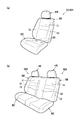
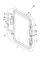
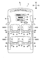
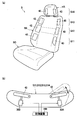
- FIG. 1 It is a figure which shows the vehicle by which the vehicle seat which concerns on one Embodiment of this invention was mounted. It is a perspective view of a vehicle seat as a vehicle seat, and is a diagram (a) showing a driver seat and a passenger seat, and a diagram (b) showing a rear seat. It is a perspective view which shows an example of the structure which changes direction of a seat surface. It is the figure which looked at the vehicle seat from the top, and is a figure (a) showing a state where a side frame is in a normal position, and a figure (b) showing a state where the right side frame rotated forward. It is a figure which shows the state which the door opened and the right side frame rotated later.
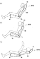
- FIG. 2 is a side view of a vehicle seat, and is a view in which the seat back is tilted backward (a), a view in which the front portion of the seat cushion is raised upward (b), and a view in which the seat back is tilted back (c).
- front and rear, left and right, and top and bottom are based on front and rear, left and right, and top and bottom of a vehicle on which a vehicle seat is mounted.
- the vehicle seat of the present embodiment is configured as a vehicle seat S mounted on a vehicle C (automobile) as an example of a vehicle.
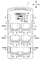
- the vehicle seat S includes a driver seat S1 on which the driver sits and a second seat S2 that is a seat other than the driver seat S1.
- the second seat S2 includes a passenger seat S21 disposed on the left side of the driver seat S1, a rear seat S22 disposed behind the driver seat S1, and a rear seat of the passenger seat S21.
- the rear seat S23 is disposed.
- the rear seats S22 and S23 are connected and configured as an integral seat.
- the passenger seat may be arranged on the right side of the driver seat.
- the rear seats S22 and S23 may be configured as independent seats that are not connected.
- the vehicle C includes a steering wheel SW operated by a driver and an operation panel OP provided on the instrument panel. Further, on the left and right outer sides of the seats S1, S21, S22, and S23 (in this embodiment, the right side of the seats S1 and S22 and the left side of the seats S21 and S23) with respect to the left and right direction of the vehicle C, respectively, A door DR that can be opened and closed is provided. An occupant (including a driver) sitting on each of the seats S1, S21, S22, and S23 can get on and off the vehicle C from the entrance of the vehicle C by opening the left and right outer doors DR.
- the vehicle C includes an automatic driving system AS, and the automatic driving mode in which the automatic driving system AS automatically performs steering, and the automatic driving system AS does not automatically perform steering, and steering by the driver is essential.
- the manual operation mode can be executed. Switching between the automatic operation mode and the manual operation mode can be performed, for example, by the driver operating the operation panel OP.
- the automatic driving mode may be a mode in which the automatic driving system AS automatically performs steering and does not automatically accelerate and brake, or the automatic driving system AS performs at least acceleration and braking in addition to steering. A mode in which one of them is automatically performed may be used.
- each of the seats S1, S21, S22, and S23 includes a seat cushion SC, a seat back SB, and a headrest HR.
- the seat backs SB of the seats S1, S21, S22, and S23 are provided on the seat center portion 11 facing the back of the occupant and on both the left and right sides of the seat center portion 11, and are in the normal position (the position shown in FIG. 4A).
- the left and right seat side portions 12 and 13 projecting to the occupant side, more specifically to the front side, from the seat center portion 11.
- a seat cushion frame (not shown) is incorporated in the seat cushion SC.
- the seat cushion SC is configured by covering the seat cushion frame with a pad material made of urethane foam or the like and a skin material made of fabric or leather.
- the seat back SB includes a seat back frame FB.
- the seat back frame FB includes a central frame 21 that constitutes the skeleton of the seat central portion 11 and side frames 22 and 23 that constitute the skeleton of the left and right seat side portions 12 and 13.
- the left and right side frames 22 and 23 are provided so that the front end portions can swing back and forth by the rear end portions being rotatably connected to the central frame 21.
- the seat back SB is configured by covering the seat back frame FB with a pad material and a skin material.
- the actuator 30 for changing the direction of the seating surface, which is the front surface of the seatback SB, to the left and right is disposed inside the seatback SB.
- One actuator 30 is arranged on each of the left and right sides of the seat back SB corresponding to the left and right side frames 22 and 23.
- the actuator 30 rotates and moves a part of the seat back SB, specifically, the side frames 22 and 23 that are part of the seat side parts 12 and 13, thereby moving the seat back SB to the direction of the seating surface. It can be changed to right and left.
- the actuator 30 rotates and moves the side frames 22 and 23 from the normal position (see FIG. 4A) before being in the direction approaching the occupant or after being in the direction away from the occupant.
- the seat back SB is configured such that the direction of the seating surface can be changed to the left and right.
- Such an actuator 30 includes a motor 31 and a gear box 32 as an example.
- the motor 31 is, for example, a stepping motor, and is configured to be capable of forward / reverse switching of the rotation direction of the shaft.
- the gear box 32 is a member that houses a plurality of gears (not shown) for decelerating and transmitting the rotational driving force of the motor 31 to the side frames 22 and 23.
- the actuator 30 is fixed to the left and right portions of the central frame 21 by a bracket (not shown).
- the seat side portions 12 and 13 are positioned at a normal position protruding a predetermined amount from the seat center portion 11 in a non-operating state.
- the motor 31 of the right actuator 30 rotates forward and the side frame 22 moves forward from the normal position under the control of the control device 100 described later. It rotates to the front position which is the position of. Accordingly, the seat side portion 12 is pushed forward from the normal position and the front surface of the seat side portion 12 is directed to the left, so that the seating surface of the seat back SB is directed to the left as a whole.
- the motor 31 of the right actuator 30 is reversely rotated to rotate the side frame 22 from the front position shown in FIG. 4B to the normal position shown in FIG. .
- the motor 31 of the left actuator 30 is rotated forward by the control of the control device 100, and the side frame 23 is rotated from the normal position to the front position.
- the seat side portion 13 is pushed forward from the normal position and the front surface of the seat side portion 13 is directed to the right, so that the seat surface of the seat back SB is directed to the right as a whole.
- the motor 31 of the left actuator 30 is reversely rotated to rotate the side frame 23 from the front position to the normal position.
- the actuator 30 can change the orientation of the seating surface of the seat back SB left and right by rotating the side frames 22 and 23 and pushing the seat side portions 12 and 13 forward from the normal position. It is configured as follows.
- the side frames 22 and 23 are rotatable between the normal position (0) and the fifth front position (5) which is the most rotated position.
- the actuator 30 By appropriately controlling the drive time of the actuator 30 (motor 31), the actuator 30 (motor 31) can be rotated forward from the normal position to an arbitrary position between the normal position and the fifth front position.
- the first front position (1) which is a position rotated before the normal position, is rotated between the normal position and the fifth front position, and the first front position is rotated.
- the second front position (2) which is the position
- the third front position (3) which is the position rotated before the second front position, and the position rotated before the third front position.
- a fourth forward position (4) is set.
- the motor 31 of the actuator 30 on the door DR (entrance / exit DE) side is reversed by the control of the control device 100, and the side frame on the entrance / exit DE side. 22 rotates from the normal position (see the two-dot chain line) to the rear position which is the rear position.
- the front surface of the seat side portion 12 on the entrance / exit DE side is substantially flat with respect to the front surface of the seat central portion 11, so that the seating surface of the seat back SB as a whole is on the entrance / exit DE side. To be directed to.
- the vehicle seat S detects a wheel speed sensor 91 that detects a wheel speed of each wheel W, a steering angle sensor 92 that detects a steering angle of the steering wheel SW, and a driver's arousal state.
- the respiration sensor 93 is a resistance pressure sensor having a circular detection surface, and is provided between the pad material and the skin material of the seat cushion SC of the driver seat S1 (see FIG. 2A).
- the respiration sensor 93 is configured so that the electrical resistance value between the electrodes decreases as the contact resistance increases by being deformed downward according to the magnitude of the pressure applied from the upper surface.
- the respiration sensor 93 outputs an electrical signal related to this electrical resistance value to the control device 100.
- the control device 100 is configured such that the left and right actuators 30 provided on the sheets S1, S21, S22, and S23 can be individually controlled.
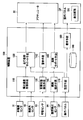
- the control device 100 includes a lateral acceleration acquisition means 110, a running posture support means 120, a wakefulness detection means 130, a warning means 140, a boarding / alighting detection means 150, a boarding / alighting support means 160, a setting means 170, and a display means. 180 and a storage device 190.
- the control device 100 includes a CPU (Central Processing Unit), a ROM (Read Only Memory), a RAM (Random Access Memory), and the like (not shown), and reads and executes programs stored in the storage device 190 in advance. Each of these means is realized.
- the lateral acceleration acquisition unit 110 is a unit that acquires the lateral acceleration applied to the vehicle C.
- the lateral acceleration acquisition unit 110 calculates the lateral acceleration GC by calculation based on the wheel speed acquired from the wheel speed sensor 91 and the steering angle acquired from the steering angle sensor 92.
- the lateral acceleration GC is positive on the right and negative on the left.
- the running posture support means 120 is a means for executing the running posture support control that controls the actuator 30 to turn the seating surface of the seat back SB in the turning direction when the vehicle C turns. Specifically, the running posture support means 120 drives the actuator 30 based on the lateral acceleration GC acquired by the lateral acceleration acquisition means 110 and rotates the side frames 22 and 23 to thereby seat the seat back SB. Change the orientation of the face.
- the running posture support means 120 starts running posture support control when the magnitude (absolute value) of the lateral acceleration GC is equal to or greater than the first acceleration threshold GCth1, and as shown in FIG.
- the actuator 30 is rotated forward to rotate the side frames 22 and 23 from the normal position to the first front position (1), and the seat side parts 12 and 13 are pushed forward to push the seat back SB. Turn the seat in the turning direction.
- the traveling posture support means 120 further rotates the actuator 30 in the forward direction for the driver seat S1. Then, the side frames 22 and 23 are rotated to the second front position (2), and the seat side portions 12 and 13 are pushed further forward so that the seating surface of the seat back SB is further directed in the turning direction.
- the running posture support means 120 indicates the amount of change in the orientation of the seating surface of the seat back SB, in this embodiment, the amount of rotation of the side frames 22 and 23. It is configured to be larger than when it is small. Note that the lateral acceleration GC increases when the turn is steep or the vehicle speed is high, and decreases when the turn is slow or the vehicle speed is low. Become.
- the running posture support means 120 reverses the actuator 30 to rotate the side frames 22 and 23. Then, the lateral acceleration GC is rotated back to a position before the magnitude of the lateral acceleration GC becomes equal to or greater than the second acceleration threshold value GCth2, and the direction of the seating surface of the seat back SB is slightly returned.
- the second reset threshold value Rth2 is set to a value smaller than the second acceleration threshold value GCth2 and larger than the first acceleration threshold value GCth1.
- the running posture support means 120 when the magnitude of the lateral acceleration GC becomes smaller than the first reset threshold Rth1, the running posture support means 120 further reverses the actuator 30 to rotate the side frames 22 and 23 to the normal position later, The orientation of the seating surface of the seat back SB is returned to the original, and the running posture support control is ended.
- the first reset threshold value Rth1 is set to a value smaller than the first acceleration threshold value GCth1.
- Each threshold is set in advance by a running test or simulation. Further, GCth1, GCth2, Rth1, Rth2 are set as positive values. In the present embodiment, since the lateral acceleration GC generated in the left direction as in a right turn is treated as negative, the magnitude of the lateral acceleration GC is, for example, in the case of GC ⁇ ⁇ GCth1 during the right turn. It is determined that the value is equal to or greater than one acceleration threshold value GCth1, and when GC> ⁇ Rth1, it is determined that the magnitude of the lateral acceleration GC is smaller than the first reset threshold value Rth1.
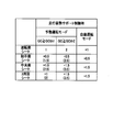
- the traveling posture support means 120 individually operates the actuators 30 of the respective sheets S1, S21, S22, S23 according to the arrangement positions of the sheets S1, S21, S22, S23 in the vehicle C when executing the traveling posture support control. It is configured to control. Specifically, when the running posture support means 120 executes the running posture support control, the amount of rotation of the side frames 22 and 23 of the second seat S2 is calculated based on the amount of rotation of the side frames 22 and 23 of the driver seat S1. Make it larger than the amount of rotation. Further, when the running posture support means 120 executes the running posture support control, the running posture support means 120 determines the amount of rotation of the side frames 22 and 23 of the rear seats S22 and S23 by rotating the side frames 22 and 23 of the passenger seat S21. Make it larger than the amount of movement.
- the running posture support means 120 rotates the side frames 22 and 23.
- the amount of movement is increased by adding 0.5 to the amount of rotation (1) of the driver's seat S1, and is rotated from the normal position to a position (1.5) intermediate between the first front position and the second front position.
- the running posture support means 120 sets the rotation amount of the side frames 22 and 23 to 0 as the rotation amount (2) of the driver seat S1. .5 is added to increase the position, and the position is rotated to an intermediate position (2.5) between the second front position and the third front position.
- the running posture support means 120 determines the amount of rotation of the side frames 22 and 23 when the lateral acceleration GC is greater than or equal to the first acceleration threshold GCth1. 1 is added to the rotation amount (1) of S1 to make it larger than the rotation amount (1.5) of the passenger seat S21, and the rotation is performed from the normal position to the second front position (2). Further, when the lateral acceleration GC is equal to or greater than the second acceleration threshold GCth2, the running posture support means 120 sets the rotation amount of the side frames 22 and 23 to the rotation amount (2) of the driver seat S1. Is added to be larger than the rotation amount (2.5) of the passenger seat S21 and is rotated to the third front position (3).
- the intermediate position between the normal position (0) and the first forward position (1) is referred to as a first intermediate position (0.5), and the first forward position (1) and the second forward position (2).
- An intermediate position between the second forward position (2) and the third forward position (3) is referred to as a third intermediate position (2.5), and the third forward position (3) and the fourth forward position (4).
- the intermediate position is referred to as a fourth intermediate position (3.5).
- An intermediate position between the fourth forward position (4) and the fifth forward position (5) is referred to as a fifth intermediate position (4.5).
- the running posture support means 120 executes the running posture support control, the amount of rotation of the side frames 22 and 23 in the automatic operation mode is changed to the side frames 22 and 23 in the manual operation mode. It is comprised so that it may become larger than the rotation amount.
- the running posture support means 120 sets the rotation amount of the side frames 22 and 23 to the rotation amount (2) in the manual operation mode. Is added to increase the rotation to the third forward position (3).
- the running posture support means 120 determines the amount of rotation of the side frames 22 and 23, The rotation amount (2) in the automatic operation mode of the driver's seat S1 is increased by adding 0.5, and is rotated from the normal position to the third intermediate position (2.5). Moreover, when the magnitude of the lateral acceleration GC becomes equal to or greater than the second acceleration threshold value GCth2, the running posture support means 120 determines the rotation amount of the side frames 22 and 23 as the rotation amount in the automatic driving mode of the driver seat S1. (3) is increased by adding 0.5 and rotated to the fourth intermediate position (3.5).
- the running posture support means 120 rotates the side frames 22 and 23. Is increased by adding 1 to the rotation amount (2) of the driver seat S1 in the automatic operation mode, and is rotated from the normal position to the third front position (3). Moreover, when the magnitude of the lateral acceleration GC becomes equal to or greater than the second acceleration threshold value GCth2, the running posture support means 120 determines the rotation amount of the side frames 22 and 23 as the rotation amount in the automatic driving mode of the driver seat S1. (1) is increased by adding 1 to (3) and rotated to the fourth forward position (4).
- the running posture support means 120 is configured to operate the actuator 30 at a slower speed when executing the running posture support control in the automatic operation mode than in the manual operation mode. Also good. According to this, since the sudden operation of the seat side portions 12 and 13 can be avoided, it is possible to suppress giving the passenger discomfort and the like.
- the arousal state detection means 130 is a means for acquiring a signal from the respiration sensor 93 and detecting the awakening state of the driver based on the signal from the respiration sensor 93.
- the wakefulness detection means 130 can determine the driver's wakefulness from the waveform of the respiratory sensor 93 as described in JP-A-2015-80521.
- a signal indicating that is provided. Output to warning means 140.
- the warning means 140 executes warning control for controlling the actuator 30 of the driver's seat S1 to change the seating direction of the seat back SB when the wakefulness detection means 130 detects a decrease in the driver's wakefulness. It is means to do. Specifically, the warning means 140 starts warning control when the wakefulness detection means 130 detects a decrease in the driver's wakefulness, and alternately forward and reverse the left and right actuators 30 of the driver seat S1. Thus, the side frames 22 and 23 are alternately rotated back and forth to change the orientation of the seating surface of the seat back SB alternately left and right.
- the warning means 140 first rotates the right actuator 30 forward to rotate the side frame 22 forward from the normal position to the fifth front position (5), and pushes the seat side part 12 forward.
- the seating surface of the seatback SB is turned to the left, and then the right actuator 30 is reversed to rotate the side frame 22 backward from the fifth front position (5) to the normal position.
- the warning means 140 rotates the left actuator 30 forward to rotate the side frame 23 forward from the normal position to the fifth forward position (5), and pushes out the seat side 13 forward to seat back.
- the seat surface of the seat back SB is turned to the right, and then the left actuator 30 is reversed to rotate the side frame 23 back from the fifth front position (5) to the normal position. return.
- the warning unit 140 repeats this series of operations in the warning control. Thereby, the warning means 140 tries to awaken the driver by swinging the upper body of the driver left and right.
- the amount of rotation of the side frames 22 and 23 when the warning control is executed is set to be larger than the amount of rotation of the side frames 22 and 23 when the warning control is not executed.
- the amount of rotation of the side frames 22 and 23 when executing the warning control is larger than the amount of rotation of the side frames 22 and 23 when the vehicle C executes the running posture support control.
- the amount of rotation (5) of the side frames 22 and 23 when executing the warning control is determined when the running posture support control is executed when the vehicle C is in the automatic driving mode. It is larger than the amount of rotation of the side frames 22 and 23 (3 at the maximum).
- the warning unit 140 may be configured to operate the actuator 30 at a faster speed when executing the warning control than when executing the driving posture support control by the driving posture support unit 120. For example, if the running posture support means 120 operates the actuator 30 at a speed that is 80% of the capacity of the actuator 30, the warning means 140 can be configured to operate the actuator 30 at a speed of 100%.
- the boarding / alighting detection means 150 is a means for detecting boarding / alighting of a passenger on the vehicle C.
- the getting-on / off detection unit 150 acquires a signal from the opening / closing detection sensor 94 that detects opening / closing of the door DR, and detects that the door DR has been opened based on the signal from the opening / closing detection sensor 94. It is determined that there is a passenger getting on and off the vehicle C.
- the boarding / alighting detection unit 150 determines that there is a boarding / alighting of the occupant on the vehicle C, the boarding / alighting detection unit 150 outputs a signal indicating this to the boarding / alighting support unit 160.
- the boarding / alighting support means 160 controls the actuator 30 on the boarding / alighting side of the seats S1, S21, S22, S23 to control the seating surface of the seatback SB. It is a means for executing boarding / alighting support control directed toward the boarding / alighting side of the vehicle C.
- the boarding / alighting support means 160 detects that the door DR is opened by the boarding / alighting detection means 150, as shown in FIG. 5, the boarding / alighting gate DE side of the vehicle seat S corresponding to the opened door DR.
- the side frames 22 and 23 are rotated from the normal position to the rear position by rotating the actuator 30 in the reverse direction so that the seating surface of the seat back SB faces the entrance / exit DE.
- the boarding / alighting support means 160 detects that the door DR is closed by the boarding / alighting detection means 150, the boarding / alighting support means 160 causes the actuator 30 on the boarding gate DE side of the vehicle seat S corresponding to the closed door DR to rotate forward.
- the frames 22 and 23 are rotated from the rear position to the normal position, and the direction of the seating surface of the seat back SB is restored.
- the amount of rotation from the normal position to the rear position of the side frames 22 and 23 when executing the getting-on / off support control is fifth from the normal position of the side frames 22 and 23 when executing the warning control. It is set to be larger than the amount of rotation to the front position. For this reason, the change amount of the seating surface direction of the seat back SB when executing the getting on / off support control is larger than the change amount of the seating surface direction of the seat back SB when executing the warning control.
- the setting means 170 is a means for setting the amount of change in the seating surface direction of the seat back SB based on information input by an occupant's operation. Can be set. Specifically, the setting means 170 is configured to be able to set the amount of rotation of the side frames 22 and 23 for each of the seats S1, S21, S22, and S23 based on information input by the occupant operating the operation panel OP. Has been. The amount of rotation of the side frames 22 and 23 can be set as the amount of rotation from the normal position to an arbitrary position between the normal position and the fifth front position (5).
- the traveling posture support unit 120 when the setting unit 170 sets the amount of rotation of the side frames 22 and 23 (the amount of change in the orientation of the seating surface of the seat back SB), the traveling posture support unit 120 is set by the setting unit 170.
- the actuator 30 is controlled according to the set rotation amount. That is, when the setting unit 170 sets the rotation amounts of the side frames 22 and 23, the traveling posture support unit 120 controls the actuator 30 with priority on the set rotation amount.
- the running posture support unit 120 does not change the side acceleration GC even when the lateral acceleration GC is greater than or equal to the first acceleration threshold GCth1.
- the part frames 22 and 23 are not rotated (the actuator 30 is not driven) and maintained at the normal position.
- the traveling posture support means 120 maintains the normal position without driving the actuator 30 even when the magnitude of the lateral acceleration GC becomes equal to or greater than the second acceleration threshold GCth2. That is, when the setting unit 170 sets the rotation amount to 0, the traveling posture support unit 120 does not execute the traveling posture support control (turns OFF).
- the traveling posture support unit 120 has a lateral acceleration GC magnitude.
- the first acceleration threshold value GCth1 or more is reached, the side frames 22 and 23 are moved from the normal position to the third position from the normal position by the rotation amount (3) set by the setting means 170 instead of the normal rotation amount (1) shown in FIG. Rotate to the forward position.
- the magnitude of the lateral acceleration GC becomes equal to or greater than the second acceleration threshold GCth2
- the running posture support means 120 maintains the third front position without rotating the side frames 22 and 23.
- the setting unit 170 determines the orientation of the seat surface when the lateral acceleration GC is greater than or equal to the first acceleration threshold GCth1 and when the lateral acceleration GC is greater than or equal to the second acceleration threshold GCth2.
- the amount of change may be individually settable.
- the warning unit 140 and the boarding / alighting support unit 160 are configured not to execute the control (set to OFF) when the setting unit 170 prohibits the execution of the warning control or the boarding / alighting support control by an occupant's operation. Also good.
- the display unit 180 is a unit that displays information on the amount of change in the seating surface orientation of the seatback SB that is currently set on the display screen DS of the operation panel OP as a display device. Specifically, the display unit 180 displays the change amount set by the setting unit 170 on the display screen DS of the operation panel OP when the setting unit 170 sets the change amount of the seating direction. When the setting unit 170 does not set the amount of change in the seating direction, the display unit 180 may display the setting value of the running posture support control on the display screen DS of the operation panel OP. It does not have to be displayed. Further, instead of the set value, the fact that the running posture support control is to be executed (that is, ON) may be displayed on the display screen DS of the operation panel OP.
- the storage device 190 is a device that stores values acquired from the sensors 91 to 94, values calculated by each means, threshold values, setting values, and the like.
- a lateral acceleration GC is generated in the vehicle C.
- the running posture support means 120 runs running posture support control that directs the seating surface of the seat back SB of each of the seats S1, S21, S22, S23 in the turning direction. Execute.
- the right actuator 30 when the vehicle is turning left, the right actuator 30 is rotated forward to move the side frame 22 from the normal position, and when the driver's seat S1, the first front position (1 ), In the case of the passenger seat S21, it is rotated to the second intermediate position (1.5), and in the case of the rear seats S22 and S23, it is rotated to the second front position (2), and the seat side portion 12 is pushed forward to seat. Turn the seat of the back SB to the left. If the vehicle is turning right, the left actuator 30 is rotated forward to move the side frame 23 from the normal position to the first front position (1), the second intermediate position (1.5), or the second front position. Rotate to (2), push the seat side portion 13 forward, and turn the seat back SB rightward.
- the traveling posture support means 120 further rotates the right actuator 30 in the forward direction when the vehicle is turning counterclockwise to move the side frame 22 to the second front position when the driver seat S1.
- the front seat S21 is rotated to the third intermediate position (2.5), and the rear seats S22 and S23 are rotated to the third front position (3) to move the seat side portion 12 further forward. Push out and turn the seat back of the seat back SB further to the left.
- the left actuator 30 is further rotated forward so that the side frame 23 moves to the second front position (2), the third intermediate position (2.5), or the third front position (3 ), The seat side portion 13 is pushed further forward, and the seat surface of the seat back SB is further directed to the right.
- the upper body of the occupant can be satisfactorily received by the seat surface of the seat back SB.
- the distance between the steering wheel SW and the seat back SB can be shortened by pushing the end of the seat back SB opposite to the left and right sides in the turning direction, thereby facilitating steering. it can.
- the running posture support means 120 reverses the actuator 30 to the side portion.
- the frames 22 and 23 are rotated back to the first front position (1), the second intermediate position (1.5), or the second front position (2), and the orientation of the seating surface of the seat back SB is slightly returned (see FIG. 8).
- the running posture support means 120 further reverses the actuator 30 and moves the side frames 22, 23 back to the normal position. Rotate to return the seating surface of the seat back SB to the original orientation (see FIG. 1).
- the arousal state detection unit 130 is based on the signal acquired from the respiration sensor 93 and the awakening state. Calculate the value indicating. Then, when it is determined that the value indicating the arousal state satisfies a predetermined arousal state threshold value and the driver's arousal state is lower than a predetermined reference, a signal indicating that is output to the warning unit 140.
- the warning means 140 executes warning control for changing the orientation of the seating surface of the seat back SB of the driver seat S1 in response to this signal.
- FIGS. 10A to 10D are repeated. That is, as shown in FIG. 10A, first, the right actuator 30 is rotated forward to rotate the side frame 22 forward from the normal position to the fifth front position (5), and the seat side portion 12 is moved. Push forward and turn the seat back SB left. Thereafter, as shown in FIG. 10B, the right actuator 30 is reversely rotated to return the seating surface of the seat back SB to the original direction. Next, as shown in FIG. 10C, the left actuator 30 is rotated forward to rotate the side frame 23 forward from the normal position to the fifth front position (5), and the seat side 13 is moved forward. And the seat surface of the seat back SB is directed to the right. Thereafter, as shown in FIG. 10D, the left actuator 30 is reversely rotated to return the seating surface of the seat back SB to the original direction. By repeating this series of operations, the upper body of the driver can be greatly swung left and right, so that the driver can be awakened.
- the driving posture support means 120 executes the driving posture support control when the driver is turning, and in such a case, the driver's arousal state may be reduced. The nature is low. For this reason, there are few situations where the running posture support control by the running posture support means 120 interferes with the warning control by the warning means 140. If the operating condition of the running posture support control and the operating condition of the warning control are satisfied at the same time, it may be configured to give priority to any control, for example, the running posture support control.
- the boarding / alighting support means 160 places the seat back SB of the corresponding seat S1, S21, S22, S23 on the vehicle.
- the boarding / alighting support control for the C side of the boarding / alighting gate DE is executed. Specifically, for example, when the door DR of the driver seat S1 is opened, the boarding / alighting support means 160 reverses the right actuator 30 to move the side frame 22 backward from the normal position as shown in FIG.
- the seat back SB is turned to the position, and the seat surface of the seat back SB is directed to the entrance / exit DE.
- the boarding / alighting support means 160 rotates the right actuator 30 in the normal direction to rotate the side frame 22 from the rear position to the normal position, thereby seating the seat back SB. Restore the orientation of the face.
- the direction of the seating surface of the seat back SB is appropriate depending on the situation in which the occupant is placed, specifically the arrangement position of the seats S1, S21, S22, S23 in the vehicle C. Can be changed. Accordingly, when the vehicle C turns, the occupant can be appropriately supported by the seat surface of the seat back SB according to the situation in which the vehicle C is placed.
- the occupant sitting on the second seat S2 does not drive by himself / herself, the occupant may not take a posture corresponding to the turning direction. Since it is larger than the seat S1, an occupant sitting on the second seat S2 can be satisfactorily received by the seat surface of the seat back SB when the vehicle C turns. Thereby, comfort can be improved.
- the change amount of the seating direction of the rear seats S22, S23 is made larger than the change amount of the seating direction of the passenger seat S21, the rear seat S22 whose front view is worse than that of the passenger seat S21. , S23 can be satisfactorily received by the seat surface of the seat back SB. Thereby, comfort can be improved.
- the amount of change in the seating surface direction of the seat back SB during the automatic operation mode is made larger than that during the manual operation mode, the situation where the occupant is placed in the seating surface direction of the seat back SB, specifically, the vehicle It can be changed according to the operation mode of C.
- the driver does not steer and may not be able to take a posture corresponding to the turning direction.
- the amount of change in the direction of the seating surface of the seat back SB in the automatic driving mode is changed to the manual driving mode.
- the vehicle C is turned larger, the occupant can be satisfactorily received by the seat surface of the seat back SB when the vehicle C turns. Thereby, comfort can be improved.
- the seating surface of the seat back SB is directed toward the entrance / exit DE of the vehicle C when the passenger gets in or out of the vehicle C, the situation in which the occupant is placed in the direction of the seating surface of the seat back SB, specifically Can be changed to an appropriate direction according to the situation of getting on and off the vehicle C. Further, since the seating surface of the seat back SB can be largely moved toward the entrance / exit DE of the vehicle C when the boarding / alighting support control is executed, it is easy to get on and off the vehicle seat S. Thereby, boarding / alighting property can be improved.
- the open / close detection sensor 94 outputs a signal indicating that the door DR is open even in a so-called half-door state
- the seat surface of the seat back SB faces the entrance / exit DE side even in the half-door state. Since it is directed, the passenger can be informed that the door DR is a half-door.
- the amount of change in the seating direction of the seat back SB of the driver's seat S1 is increased when a decrease in the driver's arousal state is detected, the situation where the occupant is placed in the seating direction of the seat back SB Specifically, it can be appropriately changed according to the driver's arousal state. Moreover, since the amount of change in the orientation of the seating surface of the seat back SB of the driver seat S1 when executing the warning control can be increased, the awakening effect can be enhanced.
- the actuator 30 rotates and moves the side frames 22 and 23 that are part of the seat side portions 12 and 13, thereby changing the orientation of the seating surface of the seat back SB.
- the actuator 30 can be reduced in size as compared with the configuration in which the orientation of the seat back is changed.
- control device 100 since the control device 100 has the setting unit 170 and the running posture support unit 120 controls the actuator 30 with priority given to the rotation amounts of the side frames 22 and 23 set by the setting unit 170, the seat back SB The amount of change in the orientation of the seat can be set according to the passenger's preference.
- the setting means 170 can set the change amount of the seating surface of the seat back SB to an arbitrary change amount including 0, the orientation of the seating surface of the seat back SB is not changed (running posture support control is performed).
- the amount of change in the orientation of the seating surface of the seat back SB can be set according to the passenger's preference, including the option of “do not execute”.
- control device 100 since the control device 100 includes the display unit 180, information on the amount of change in the seating direction of the seat back SB that is currently set can be displayed on the display screen DS of the operation panel OP to notify the occupant.
- control device may be configured to correct the rotation amount of the side frame according to the inclination angle of the seat back or the seat cushion.
- the control device normally sets the amount of rotation of the side frame when the tilt angle of the seat back SB is equal to or greater than the back angle threshold (first back angle threshold). For example, the rotation amount may be increased by adding 1, for example.
- the vehicle seat S has a configuration in which the front portion of the seat cushion SC is moved up and down by the tilt mechanism TL and the inclination angle of the seating surface of the seat cushion SC can be changed.
- the amount of rotation of the side frame may be increased by adding 1 to the normal rotation amount, for example.
- the side frame 1 may be added to the normal rotation amount (1) (see FIG. 7) to rotate from the normal position to the second front position (2).
- the inclination angle of the seat back SB is the first back angle described above.
- the amount of rotation of the side frame May be rotated from the normal position to the fourth intermediate position (3.5) by adding 2 to the normal rotation amount (1.5) (see FIG. 7).
- the second seat S2 includes the passenger seat S21 and the rear seats S22 and S23, but is not limited thereto.
- the second seat S2 includes a passenger seat S21, a center seat S24 disposed behind the driver seat S1, and a center seat disposed behind the passenger seat S21.
- the configuration may include S25, the third row seat S26 disposed behind the central seat S24, and the third row seat S27 disposed behind the central seat S25.
- the control device 100 (running posture support means) has center seats S24 and S25.
- the rotation amount of the side frames 22 and 23 is added to the rotation amount (1) of the driver seat S1 by 1.5. Increase and rotate from the normal position to the third intermediate position (2.5).
- the rotation amount of the side frames 22, 23 is increased by adding 1.5 to the rotation amount (2) of the driver seat S1. And rotated to the fourth intermediate position (3.5).
- 1.5 is added to the rotation amount (2 or 3) of the driver seat S1 in the automatic operation mode.
- the control device 100 determines the amount of rotation of the side frames 22 and 23 for the driver seat S1.
- the rotation amount (1) is increased by adding 1, and the rotation amount is rotated from the normal position to the second front position (2).
- the rotation amount of the side frames 22, 23 is increased by adding 1.5 to the rotation amount (2) of the driver seat S1.
- the fourth intermediate position (3.5) is added to the rotation amount (2 or 3) of the driver seat S1 in the automatic operation mode.
- boarding / alighting to the third row seats S26, S27 is performed from doors DR (boarding gates) provided on the left and right outer sides of the center seats S24, S25. That is, doors for getting on and off are not provided on the left and right sides of the third row seats S26 and S27.
- the control device 100 boarding / alighting support means
- the control device 100 does not execute the boarding / alighting support control (see FIG. 5) for the third row seats S26 and S27.
- the control device 100 further includes attachment detection means for detecting whether or not the child seat is attached to the vehicle seat S, and the traveling posture support means attaches the child seat to the vehicle seat S by the attachment detection means.
- the amount of rotation of the side frames 22 and 23 when executing the running posture support may be increased.
- the rotation amount of the side frame 22 is increased by adding, for example, 1 to the normal rotation amount (2.5) (see FIG. 13), and as shown in FIG. You may make it rotate to a 4th intermediate position (3.5).
- the attachment detection means detects that the child seat S3 is attached to the vehicle seat S
- the control device 100 does not drive the actuator 30 of the vehicle seat S to which the child seat S3 is attached (the seat surface). (The orientation is not changed).
- the center seats S24 and S25 may be provided so as to be rotatable with respect to the vehicle body so as to face rearward.
- the control device 100 further includes a direction detection unit that detects the direction of the central seats S24 and S25, and the traveling posture support unit is such that the central seats S24 and S25 are directed rearward by the direction detection unit. Is detected, the side frame 23 is rotated when turning left, and the side frame 22 is rotated when turning right. Further, for example, when the center seat S24 is facing forward (see FIG. 12), the side frame 22 on the entrance / exit side is rotated during the entrance / exit support control. When it is detected that the center seat S24 is facing backward, the side frame 23 moved to the entrance / exit (door DR) side is rotated contrary to when it is facing forward.
- the control device 100 may further include a traveling direction information acquisition unit 210 and a turn notification unit 220.
- the traveling direction information acquisition unit 210 is a unit that acquires information on the traveling direction of the vehicle C. Specifically, the traveling direction information acquisition unit 210 acquires information on the traveling direction of the vehicle C from the car navigation system NS mounted on the vehicle C, specifically, information on a curve or an intersection in the traveling direction of the vehicle C. To do.
- the turning notification means 220 controls the actuator 30 of the driver's seat S1 and controls the seat surface of the seat back SB before the vehicle C actually turns based on the information on the traveling direction acquired by the traveling direction information acquisition means 210. This is means for executing turning notification control for notifying the occupant of turning by changing the direction of the vehicle. Specifically, the turning notification unit 220 performs turning notification control when the traveling direction information acquisition unit 210 detects information such as a curve or an intersection in the traveling direction of the vehicle C.
- the turning notification unit 220 predicts the turning direction of the vehicle C from the information on the traveling direction of the vehicle C detected by the traveling direction information acquisition unit 210. Then, when the predicted turning direction is the left, the turning notification means 220 rotates the right actuator 30 of the driver seat S1 in the normal direction to move the side frame 22 from the normal position to the first intermediate position (0. 5), the seat side portion 12 is pushed forward, the seat surface of the seat back SB is directed to the left, and then the right actuator 30 of the driver seat S1 is reversed to move the side frame 22 to the first position. 1 Rotate later from the intermediate position to the normal position to return the seating surface of the seat back SB.
- the turning notification unit 220 rotates the left actuator 30 of the driver seat S1 in the normal direction so that the side frame 23 is moved from the normal position to the first intermediate position (0. 5), the seat side portion 13 is pushed forward, the seat surface of the seat back SB is directed to the right, and then the left actuator 30 of the driver seat S1 is reversed to move the side frame 23 to the first position. 1 Rotate later from the intermediate position to the normal position to return the seating surface of the seat back SB.
- the turning notification means 220 repeats this series of operations several times in turning notification control. Accordingly, the driver can push the driver several times toward the turning direction by the seat side parts 12 and 13, so that the driver should turn, specifically, turn and inform the turning direction. it can.
- the amount of rotation of the side frames 22 and 23 is preferably at a level at which the driver does not feel uncomfortable, and here, a small amount of rotation, for example, the first intermediate position (0.5) is set.
- the amount of rotation of the side frames 22 and 23 is not limited to this.
- the turning notification means 220 may be configured to change the turning amount of the side frames 22 and 23 according to the position of the vehicle C from the turning start point such as an entrance of a curve or an intersection.
- the turning notification means 220 turns the side frames 22 and 23 from the normal position to the first intermediate position (0.5) at a first point before the turning start point, for example, 50 m before the turning start point.
- the side frames 22 and 23 from the normal position to the first forward position (1) at a second point closer to the turning start point than the first point, for example, 25 m before the turning start point.
- a third point closer to the turning start point than the two points, for example, 15 m before the turning start point, is configured to rotate the side frames 22 and 23 from the normal position to the second forward position (2).
- the turning amount of the side frames 22 and 23 is increased as the turning start point is approached, and the amount of pushing forward of the seat side portions 12 and 13 is gradually increased to effectively notify the turning. And forgetting to turn can be further suppressed.
- the side frames 22 at the second point and the third point, 23 may be configured to reduce the amount of rotation, or may be configured not to drive the actuator 30 at the second point or the third point. According to this, since an unnecessary operation of the actuator 30 can be restricted, it is possible to suppress the driver from feeling uncomfortable.
- the turning notification means 220 does not notify the turning by pressing the driver several times in the turning direction by the seat side parts 12 and 13, but for example, as the vehicle approaches the entrance of a curve or an intersection, the side frame 22 is approached. , 23 may be gradually increased, and the amount of push forward of the seat side portions 12, 13 may be gradually increased to inform the driver of turning. In this case, before the vehicle C starts turning, the control device 100 gradually increases the amount of push forward of the seat side parts 12 and 13 by turning notification control, and when the vehicle C starts turning.
- the running posture support control may be executed continuously without returning the seat side portions 12 and 13 to the normal position.
- the turning notification means 220 may be configured to execute turning notification control for the second seat S2 other than the driver seat S1.
- the turning notification means 220 gradually increases the push-out amount of the seat side portions 12 and 13 by turning notification control before starting the turning, and when the turning is started, It is preferable that the running posture support control is continuously executed without returning the seat side portions 12 and 13 to the normal position. According to this, since the sudden operation of the seat side portions 12 and 13 of the second seat S2 can be avoided, the comfort can be improved.
- the turning notification unit 220 rotates the side frame 23 forward by rotating the left actuator 30 which is the same as the turning direction, so that the seat side 13 is moved.
- the operation of pushing forward, then rotating the left actuator 30 reversely to turn the side frame 23 later, and returning the seat side 13 to the original may be repeated several times.
- the right actuator 30 is driven.
- the turning notification means 220 may be configured to push the driver by the seat side portions 12 and 13 on the turning direction side.
- the turning notification means 220 is set by the setting means 170 when the setting means 170 sets the amount of rotation of the side frames 22 and 23 (the amount of change in the seating surface direction of the seat back SB) by the occupant's operation.
- the actuator 30 may be controlled according to the amount of rotation.
- the turning notification unit 220 may be configured to turn off the turning notification control when the setting unit 170 prohibits the execution of the turning notification control by an occupant's operation.
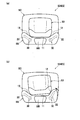
- the vehicle seat S has a plurality of support portions S11 to S14 that support different parts of the occupant, and the orientations of the seating surfaces of the support portions S11 to S14 are individually set. It may be configured to be changeable.
- the seat back SB includes a waist support portion S11 that supports the occupant's waist, a shoulder support portion S13 that is disposed on the waist support portion S11 and supports the shoulder of the occupant, and a waist support portion S11.
- a chest support part S12 disposed between the shoulder support part S13 and supporting the occupant's chest (the part between the waist and the shoulder), and the headrest HR is a head part that supports the occupant's head. It has support part S14.
- a pair of left and right support members 42 and 43 and actuators 30A and 30B are arranged on the left and right sides in each of the support portions S11 to S14, as shown in FIG.
- the support members 42 and 43 are plate-like members, and the left and right inner end portions are rotatably connected to a frame (not shown) of the seat back SB and the headrest HR so that the left and right outer end portions are It is provided so that it can swing back and forth.
- the actuators 30A and 30B correspond by rotating the corresponding support members 42 and 43 back and forth to push the seating surfaces of the support portions S11 to S14 forward or return them to their original positions. It is configured so that the orientation of the seating surfaces of the support portions S11 to S14 can be changed to the left and right.
- the waist is an example of the first part of the occupant
- the waist support part S11 is an example of the first support part
- the actuators 30A and 30B of the waist support part S11 are examples of the first actuator.
- the shoulder, chest and head are examples of a second part different from the first part of the occupant
- the chest support part S12, the shoulder support part S13 and the head support part S14 are the second support part.
- the actuators 30A and 30B of the support portions S12 to S14 are examples of the second actuator.
- the control device 100 is configured to be able to individually control the drive amounts of the eight actuators 30A and 30B arranged in total in the respective support portions S11 to S14. Accordingly, the vehicle seat S can individually change the orientation of the seating surfaces of the support portions S11 to S14.
- the running posture support means when the running posture support means executes the running posture support control, the running posture support means changes the amount of change in the seating direction of the support portions S12 to S14 from the amount of change in the seating direction of the waist support portion S11. Is also configured to be small. Specifically, when the running posture support control is executed, the running posture support means sets the actuators 30A and 30B of the support portions S12 to S14 to a drive amount of the actuators 30A and 30B of the waist portion support portion S11, more than 1. Drive with a drive amount multiplied by a small coefficient.
- the actuators 30A and 30B of the chest support part S12 are driven by a drive amount obtained by multiplying the drive amount of the actuators 30A and 30B of the waist support part S11 by a factor of 0.9, and the actuators 30A and 30A of the shoulder support part S13 are driven.
- 30B is driven by a drive amount obtained by multiplying the drive amount of the actuators 30A, 30B of the waist support part S11 by a factor of 0.8
- the actuators 30A, 30B of the head support part S14 are driven by the actuators 30A, 30A of the waist support part S11. It is driven with a driving amount obtained by multiplying the driving amount of 30B by a coefficient of 0.5.
- the coefficient can be set in advance by a running test or a simulation.
- the driving posture support means When the driving posture support control is executed, if the driving amount of the actuators 30A, 30B (the amount of change in the orientation of the seating surface) is small, the driving posture support means performs the actuators 30A, 30B of the support portions S11 to S14.
- the driving amounts are equal to each other and the driving amounts of the actuators 30A and 30B are large, the driving amounts of the actuators 30A and 30B of the support portions S12 to S14 are multiplied by a coefficient, for example, and the actuators 30A and 30B of the waist support portion S11. It may be configured to be smaller than the drive amount.
- the running posture support means may be configured to operate the actuators 30A and 30B at a slower speed than the case of the other support portions S11 to S13, for example, for the head support portion S14. According to this, it can suppress giving a discomfort etc. to a passenger
- the wakefulness detection unit 130 is configured to detect the wakefulness of the driver sitting on the driver's seat S1, but the present invention is not limited to this.
- a respiration sensor is provided on a second seat that is a seat other than the driver's seat, and the arousal state detecting means awakens an occupant sitting on the second seat based on a signal from a respiration sensor provided on the second seat.
- the state specifically, whether the occupant sitting on the second seat is asleep may be detected.
- the running posture support means The rotation amount may be configured to be larger than the rotation amount when not sleeping. For example, as shown in FIG.
- the travel posture support means determines the amount of rotation of the side frame of the passenger seat S21 when not sleeping.
- the amount of rotation of the side frames of the rear seats S22 and S23 is set to the rotation amount when not sleeping. You may be comprised so that 1.5 may be added to dynamic amount.
- the running posture support means determines the amount of rotation of the side frame. Further, 1.5 may be added to the amount of rotation when not sleeping.
- the running posture support means is configured to operate the actuator at a slower speed when the occupant sitting on the second seat, which is a seat other than the driver's seat, is sleeping. May be. Further, when executing the running posture support control, the running posture support means drives the actuator only for the driver's seat when the occupant sitting on the second seat is sleeping, and the actuator for the second seat. It is good also as a structure which is not driven.
- the running posture support means 120 is configured to determine that a predetermined turn or more has been performed based on the lateral acceleration GC.
- the present invention is not limited to this.
- the running posture support means may be configured to determine that a predetermined turn or more has been performed based on the steering angle.
- the setting value of the running posture support control may be set in multiple stages so that it increases when the turning is steep and decreases when the turning is slow, depending on the steering angle. Good.
- the vehicle body speed may be taken into account.
- the driving posture support control when executed, if the driver's seat S1 turns slowly during low speed running (small steering angle), the driver seat S1 rotates to the first front position (1).
- the vehicle When the vehicle is turning sharply at a low speed (large steering angle), the vehicle is rotated to the second front position (2).
- the second intermediate position (1) is used. .5), and when the vehicle turns sharply at high speed (large steering angle), it may be configured to rotate to the third front position (3).
- a small steering angle is when the steering angle is greater than or equal to the first steering angle threshold
- a large steering angle is when the steering angle is greater than or equal to the second steering angle threshold greater than the first steering angle threshold. It is. Further, when traveling at low speed, the vehicle body speed V is less than the speed threshold Vth, and when traveling at high speed, the vehicle body speed V is greater than or equal to the speed threshold Vth.
- the running posture support means 120 executes the running posture support control
- the amount of rotation of the side frames 22 and 23 of the rear seats S22 and S23 is determined by the side frame of the passenger seat S21. Although it was configured to be larger than the amount of rotation of 22 and 23, it is not limited to this.
- the running posture support means equalizes the turning amount of the side frame of the rear seat and the turning amount of the side frame of the passenger seat (the same turning amount). It may be configured as follows.
- the control device 100 controls the actuator 30 when the occupant switches the operation mode of the vehicle C from one of the automatic operation mode and the manual operation mode by operating the operation panel OP, etc. You may be comprised so that a passenger
- the left and right actuators 30 of the driver's seat S1 are alternately rotated forward and backward to change the orientation of the seating surface of the seat back SB alternately.
- the operation pattern of the actuator during the warning control is not limited to this.
- the right actuator 30 is slightly forward rotated, then temporarily stopped, and then further forward rotated to push the sheet side portion 12 forward in two stages, and then the right actuator 30 is reversed to reverse the sheet side portion. 12 is returned to the original position, and then the left actuator 30 is slightly forward rotated, then temporarily stopped, and then further forward rotated to push the seat side portion 13 forward in two stages.
- seat side part 13 to the original position may be sufficient.
- the right actuator 30 is reciprocated twice in the forward / reverse and forward / reverse directions to push the seat side 12 forward twice, and then the left actuator 30 in the forward / reverse / forward rotation -The pattern which repeats the operation
- the sheet side portion 13 is pushed forward once, and then the right actuator 30 is reciprocated once forward and backward to push the seat side portion 12 forward once
- a pattern in which the operation of pushing the sheet side portion 13 forward twice by reciprocating the actuator 30 twice in the normal rotation / reverse rotation and the normal rotation / reverse rotation may be used.
- the right side actuator 30 is rotated forward and backward once to push the seat side portion 12 forward one time, and then the left actuator 30 is reciprocated twice forward and backward and forward and backward. By doing so, the pattern of repeating the operation of pushing the sheet side portion 13 forward twice may be used.
- the wakefulness detection means is exemplified by means for detecting the wakefulness of the occupant based on the signal from the respiratory sensor 93, but is not limited thereto.
- the wakefulness detection means is an appropriate means that can be used by those skilled in the art, such as a means for detecting the wakefulness from an image obtained by photographing the occupant's face and a means for detecting the wakefulness from data of the occupant's heart Can do.
- the getting on / off detecting means a means for detecting that there is getting on and off the vehicle C when detecting that the door DR is opened based on the signal of the open / close detection sensor 94 is exemplified. It is not limited to this.
- the boarding / alighting detection means is a means for predicting boarding / alighting of the occupant and activating the boarding / alighting support means early, for example, a means for detecting that there is a boarding / alighting of the occupant when the door is unlocked. Also good.
- the vehicle seat S is a case where the boarding / alighting support control is executed, and particularly when an occupant gets into the vehicle C, cold air and warm air are introduced from the surface of the seat side portion 12.
- the air-conditioning air such as wind may be blown out to the left and right sides, that is, toward an occupant trying to get into the vehicle C.
- the control device 100 has seating detection means for detecting whether or not an occupant is sitting on the vehicle seat S, and the boarding / alighting support means detects that the door DR is opened by the boarding / alighting detection means.
- the getting-on / off support means detects that the occupant is sitting on the vehicle seat S by the seating detection means when it is detected that the door DR is opened by the getting-on / off detection means, it is at the time of getting off the seat back SB.
- the operation of directing the seat surface toward the entrance / exit DE is performed, and the operation of blowing out the conditioned air from the surface of the seat side portion 12 is not performed.
- the seating detection means can detect whether or not an occupant is sitting on the vehicle seat S based on output signals from a weight detection sensor, a pressure detection sensor, and the like provided in the seat cushion SC, for example. .
- the actuator 30 is configured to change the orientation of the seating surface of the seat back SB by moving the side frames 22 and 23 that are part of the seat side portions 12 and 13. It is not limited to.
- the actuator may be configured such that the orientation of the seating surface of the seat back SB can be changed by moving the entire side of the seat.
- the actuator may be configured such that the orientation of the seating surface of the seat back can be changed by moving the entire seat back by rotating the seat back.
- the actuator may be configured to change the orientation of the seating surface of the seat cushion instead of the seat back.
- the orientation of the seat cushion seat surface can be changed, for example, by moving at least a portion of the seat cushion.
- the vehicle seat may be configured to be able to change both the orientation of the seating surface of the seat back and the orientation of the seating surface of the seat cushion.
- the actuator may be configured such that the orientation of the seating surface can be changed by moving the entire seat by rotating the seat.
- the mechanism for changing the direction of the seat surface of the vehicle seat to the left and right is not limited to the mechanism described in the above embodiment.
- a mechanism for changing the orientation of the seating surface to the left and right by directing the direction of the plate-like member arranged between the left and right side frames to the left and right as described in Patent Documents 1-3. May be.
- vehicle seat S mounted in a motor vehicle was illustrated as a vehicle seat, it is not limited to this,
- a vehicle seat is vehicles other than a motor vehicle, for example, a rail vehicle, a ship, an aircraft, etc. It may be a seat to be mounted on.
Landscapes
- Engineering & Computer Science (AREA)
- Transportation (AREA)
- Mechanical Engineering (AREA)
- Aviation & Aerospace Engineering (AREA)
- Automation & Control Theory (AREA)
- Human Computer Interaction (AREA)
- Seats For Vehicles (AREA)
- Chair Legs, Seat Parts, And Backrests (AREA)
Abstract
車両用シート(S)の少なくとも一部である側部フレーム(22,23)を前後に回動させて動かすことでシートバック(SB)の座面の向きを左右に変えることが可能なアクチュエータ(30)と、アクチュエータ(30)を制御する制御装置(100)とを備える。制御装置(100)は、車両(C)が旋回するときにアクチュエータ(30)を制御してシートバック(SB)の座面を旋回方向に向ける走行姿勢サポート制御を実行する走行姿勢サポート手段を有する。走行姿勢サポート手段は、走行姿勢サポート制御を実行するときに、車両(C)内におけるシート(S1,S21,S22,S23)の位置に応じて、アクチュエータ(30)を制御する。
Description
本発明は、座面の向きを左右に変えることが可能な乗物用シートに関する。
従来、乗物用シートとして、座面の向きを左右に変えることが可能に構成されたものが知られている。例えば、特許文献1-3には、シートバックの左右のサイドフレームの間に配置された背板や受圧部材と呼ばれる板状の部材の向きを左または右に向けることで、シートバックの座面の向きを左または右に変えることが可能な乗物用シートが開示されている。
また、シートバックの座面の向きを変えるための機構としては、特許文献1-3に開示された機構のほか、例えば、特許文献4に開示されたサイドサポート駆動機構などを利用することができる。具体的には、サイドサポート駆動機構を構成する左右のサイドサポート装置が独立して駆動するようにケーブル牽引機構を設けた上で、例えば、左のサイドサポート装置を駆動させることで、左の支持部材が前に回動し、これによって、シートバックの左の側部を前に押し出すことができる。そして、このようにシートバックの左の側部が前に押し出されると、シートバックは、座面が全体として右を向くことになるので、シートバックの座面の向きを変えることが可能となる。
ところで、乗物用シートの座面の向きは、乗物用シートに座る乗員が置かれた状況に応じて変更できることが望ましい。
そこで、本発明は、座面の向きを乗員が置かれた状況に応じて変更することができる乗物用シートを提供することを目的とする。
また、本発明は、座面の向きを変えることが可能な乗物用シートの様々な利用法を提案することを目的とする。
また、本発明は、快適性を向上させることを目的とする。
また、本発明は、乗降性を向上させることを目的とする。
また、本発明は、覚醒効果を高めることを目的とする。
また、本発明は、座面の向きを変えるためのアクチュエータを小型化することを目的とする。
また、本発明は、座面の向きの変更量を乗員の好みに合わせて設定することを目的とする。
また、本発明は、現在設定されている座面の向きの変更量の情報を乗員に知らせることを目的とする。
また、本発明は、座面の向きを変えることが可能な乗物用シートの様々な利用法を提案することを目的とする。
また、本発明は、快適性を向上させることを目的とする。
また、本発明は、乗降性を向上させることを目的とする。
また、本発明は、覚醒効果を高めることを目的とする。
また、本発明は、座面の向きを変えるためのアクチュエータを小型化することを目的とする。
また、本発明は、座面の向きの変更量を乗員の好みに合わせて設定することを目的とする。
また、本発明は、現在設定されている座面の向きの変更量の情報を乗員に知らせることを目的とする。
前記した目的を達成するため、本発明の乗物用シートは、シートの少なくとも一部を動かすことで座面の向きを左右に変えることが可能なアクチュエータと、前記アクチュエータを制御する制御装置と、を備え、前記制御装置は、乗物が旋回するときに前記アクチュエータを制御して座面を旋回方向に向ける走行姿勢サポート制御を実行する走行姿勢サポート手段を有し、前記走行姿勢サポート手段は、前記走行姿勢サポート制御を実行するときに、乗物内におけるシートの位置に応じて、前記アクチュエータを制御することを特徴とする。
このような構成によれば、座面の向きを乗員が置かれた状況に応じて変更することができる。
前記した乗物用シートにおいて、乗物用シートは、運転席シートと、前記運転席シート以外のシートである第2シートとを含み、前記走行姿勢サポート手段は、前記走行姿勢サポート制御を実行するときに、前記第2シートの座面の向きの変更量を、前記運転席シートの座面の向きの変更量よりも大きくする構成とすることができる。
これによれば、第2シートに座る乗員は、自分で運転しないため、旋回方向に応じた姿勢をとれない場合があるが、第2シートの座面の向きの変更量を運転席シートの座面の向きの変更量よりも大きくすることで、乗物が旋回するときに第2シートに座る乗員を座面で良好に受け止めることができる。これにより、快適性を向上させることができる。
前記した乗物用シートにおいて、前記第2シートは、前記運転席シートの右または左に配置された助手席シートと、前記運転席シートおよび前記助手席シートの後方に配置された後席シートとを含み、前記走行姿勢サポート手段は、前記走行姿勢サポート制御を実行するときに、前記後席シートの座面の向きの変更量を、前記助手席シートの座面の向きの変更量以上とする構成とすることができる。
これによれば、特に、後席シートの座面の向きの変更量を助手席シートの座面の向きの変更量よりも大きくすることで、前方の視界が助手席シートよりも悪い後席シートに座る乗員を座面で良好に受け止めることができる。これにより、快適性を向上させることができる。
前記した乗物用シートにおいて、前記走行姿勢サポート手段は、前記走行姿勢サポート制御を実行するときに、乗物が操舵を自動的に行う自動運転モードである場合の座面の向きの変更量を、乗物が操舵を自動的に行わない手動運転モードである場合の座面の向きの変更量よりも大きくする構成とすることができる。
これによれば、自動運転モードの場合は、操舵しないため、旋回方向に応じた姿勢をとれない場合があるが、自動運転モードである場合の座面の向きの変更量を手動運転モードである場合の座面の向きの変更量よりも大きくすることで、乗物が旋回するときに乗員を座面で良好に受け止めることができる。これにより、快適性を向上させることができる。
前記した乗物用シートにおいて、前記制御装置は、乗員の乗物への乗降を検出する乗降検出手段と、前記乗降検出手段が乗員の乗物への乗降を検出した場合に、前記アクチュエータを制御して座面を乗物の乗降口側に向ける乗降サポート手段とを有する構成とすることができる。
これによれば、乗降サポート制御を実行するときに座面を乗物の乗降口側に向けて大きく動かすことができるので、乗物用シートに乗り降りしやすくなる。これにより、乗降性を向上させることができる。
前記した乗物用シートにおいて、前記制御装置は、運転者の覚醒状態を検出する覚醒状態検出手段と、前記覚醒状態検出手段が運転者の覚醒状態の低下を検出した場合に、前記アクチュエータを制御して座面の向きを変更する警告制御を実行する警告手段とを有し、前記警告制御を実行するときの座面の向きの変更量は、前記警告制御を実行しないときの座面の向きの変更量よりも大きい構成とすることができる。
これによれば、警告制御を実行するときの座面の向きの変更量を大きくできるので、覚醒効果を高めることができる。
前記した乗物用シートにおいて、前記制御装置は、運転者の覚醒状態を検出する覚醒状態検出手段と、前記覚醒状態検出手段が運転者の覚醒状態の低下を検出した場合に、前記アクチュエータを制御して座面の向きを変更する警告制御を実行する警告手段とを有し、前記走行姿勢サポート手段は、前記走行姿勢サポート制御を実行するときに、乗物が操舵を自動的に行う自動運転モードである場合の座面の向きの変更量を、乗物が操舵を自動的に行わない手動運転モードである場合の座面の向きの変更量よりも大きくするように構成され、前記警告制御を実行するときの座面の向きの変更量は、乗物が前記自動運転モードである場合に前記走行姿勢サポート制御を実行するときの座面の向きの変更量よりも大きい構成とすることができる。
これによれば、警告制御を実行するときの座面の向きの変更量を大きくできるので、覚醒効果を高めることができる。
前記した乗物用シートにおいて、前記制御装置は、乗員の乗物への乗降を検出する乗降検出手段と、前記乗降検出手段が乗員の乗物への乗降を検出した場合に、前記アクチュエータを制御して座面を乗物の乗降口側に向ける乗降サポート制御を実行する乗降サポート手段と、運転者の覚醒状態を検出する覚醒状態検出手段と、前記覚醒状態検出手段が運転者の覚醒状態の低下を検出した場合に、前記アクチュエータを制御して座面の向きを変更する警告制御を実行する警告手段とを有し、前記乗降サポート制御を実行するときの座面の向きの変更量は、前記警告制御を実行するときの座面の向きの変更量よりも大きい構成とすることができる。
これによれば、乗降サポート制御を実行するときに座面を乗物の乗降口側に向けて大きく動かすことができるので、乗物用シートに乗り降りしやすくなる。これにより、乗降性を向上させることができる。
前記した乗物用シートにおいて、前記制御装置は、乗物の進行方向の情報を取得する進行方向情報取得手段と、前記進行方向情報取得手段が取得した進行方向の情報に基づいて乗物が旋回する前に前記アクチュエータを制御して座面の向きを変更することで乗員に旋回を知らせる旋回報知手段とを有する構成とすることができる。
これによれば、乗物が旋回する前に乗員に乗物の旋回を知らせることができるので、交差点などでの曲がり忘れを抑制したり、旋回方向に応じた姿勢を予めとったりすることができる。これにより、快適性を向上させることができる。
前記した乗物用シートにおいて、シート中央部と、シート中央部の左右両側に設けられ、通常位置で前記シート中央部よりも乗員側に張り出した左右のシート側部とを有し、前記アクチュエータは、前記シート側部の少なくとも一部を、前記通常位置から、乗員に近づく方向または乗員から離れる方向に動かすことで座面の向きを変えるように構成されている構成とすることができる。
これによれば、シート全体を動かして座面の向きを変える構成と比較して、座面の向きを変えるためのアクチュエータを小型化することができる。
前記した乗物用シートにおいて、乗員の第1部位を支持する第1支持部と、乗員の前記第1部位とは異なる第2部位を支持する第2支持部とを有し、前記アクチュエータは、前記第1支持部の座面の向きを左右に変える第1アクチュエータと、前記第2支持部の座面の向きを左右に変える第2アクチュエータとを含み、前記走行姿勢サポート手段は、前記走行姿勢サポート制御を実行するときに、前記第2支持部の座面の向きの変更量を、前記第1支持部の座面の向きの変更量よりも小さくする構成とすることができる。
これによれば、乗物が旋回するときに乗員の異なる部位をそれぞれ適切な向きとした各支持部の座面で良好に受け止めることができる。これにより、快適性を向上させることができる。
前記した乗物用シートにおいて、前記制御装置は、乗員の操作によって入力された情報に基づいて座面の向きの変更量を設定する設定手段を有し、前記走行姿勢サポート手段は、前記設定手段が座面の向きの変更量を設定した場合は、前記設定手段によって設定された座面の向きの変更量に応じて前記アクチュエータを制御する構成とすることができる。
これによれば、座面の向きの変更量を乗員の好みに合わせて設定することができる。
前記した乗物用シートにおいて、前記設定手段は、座面の向きの変更量を、0を含む任意の変更量に設定可能である構成とすることができる。
これによれば、座面の向きを変えない(走行姿勢サポート制御を実行しない)という選択肢を含めて座面の向きの変更量を乗員の好みに合わせて設定することができる。
前記した乗物用シートにおいて、前記制御装置は、現在設定されている座面の向きの変更量の情報を表示装置に表示させる表示手段を有する構成とすることができる。
これによれば、現在設定されている座面の向きの変更量の情報を乗員に知らせることができる。
以下、添付の図面を参照しながら、発明の一実施形態について説明する。なお、本明細書において、前後、左右、上下は、乗物用シートが搭載された乗物の前後、左右、上下を基準とする。
図1に示すように、本実施形態の乗物用シートは、乗物の一例としての車両C(自動車)に搭載される車両用シートSとして構成されている。
図1に示すように、本実施形態の乗物用シートは、乗物の一例としての車両C(自動車)に搭載される車両用シートSとして構成されている。
車両用シートSは、運転者が座る運転席シートS1と、運転席シートS1以外のシートである第2シートS2とを含んでいる。本実施形態において、第2シートS2は、運転席シートS1の左に配置された助手席シートS21と、運転席シートS1の後方に配置された後席シートS22と、助手席シートS21の後方に配置された後席シートS23とを含んでいる。後席シートS22,S23はつながっており、一体のシートとして構成されている。なお、助手席シートは、運転席シートの右に配置されていてもよい。また、後席シートS22,S23は、つながっていない独立したシートとして構成されていてもよい。
車両Cは、運転者によって操作されるステアリングホイールSWと、インストルメントパネルに設けられた操作パネルOPとを備えている。また、車両Cの左右方向を基準として、各シートS1,S21,S22,S23の左右外側(本実施形態では、シートS1,S22の右側、シートS21,S23の左側)には、それぞれ、車体に対して開閉可能なドアDRが設けられている。各シートS1,S21,S22,S23に座る乗員(運転者を含む)は、左右外側のドアDRを開くことで、車両Cの乗降口から車両Cに乗り降りできるようになっている。
また、車両Cは、自動運転システムASを備えており、自動運転システムASが操舵を自動的に行う自動運転モードと、自動運転システムASが操舵を自動的に行わず、運転者による操舵が必須の手動運転モードとを実行可能に構成されている。自動運転モードと手動運転モードの切替は、例えば、運転者が操作パネルOPを操作することで行うことができる。なお、自動運転モードは、自動運転システムASが操舵を自動的に行い、加速および制動を自動的に行わないモードであってもよいし、自動運転システムASが操舵に加え、加速および制動の少なくとも一方を自動的に行うモードであってもよい。
図2(a),(b)に示すように、各シートS1,S21,S22,S23は、それぞれ、シートクッションSCと、シートバックSBと、ヘッドレストHRとを備えている。また、各シートS1,S21,S22,S23のシートバックSBは、乗員の背中と対面するシート中央部11と、シート中央部11の左右両側に設けられ、通常位置(図4(a)の位置)でシート中央部11よりも乗員側、具体的には、前側に張り出した左右のシート側部12,13とを有している。
シートクッションSCには、図示しないシートクッションフレームが内蔵されている。シートクッションSCは、当該シートクッションフレームに、ウレタンフォームなどからなるパッド材と、布地や皮革などからなる表皮材を被せることで構成されている。
シートクッションSCには、図示しないシートクッションフレームが内蔵されている。シートクッションSCは、当該シートクッションフレームに、ウレタンフォームなどからなるパッド材と、布地や皮革などからなる表皮材を被せることで構成されている。
また、図3に示すように、シートバックSBには、シートバックフレームFBが内蔵されている。シートバックフレームFBは、シート中央部11の骨格を構成する中央部フレーム21と、左右のシート側部12,13の骨格を構成する側部フレーム22,23とを有している。左右の側部フレーム22,23は、それぞれ、後端部が中央部フレーム21に回動可能に連結されていることで、前端部が前後に揺動可能となるように設けられている。シートバックSBは、シートバックフレームFBにパッド材と表皮材を被せることで構成されている。
シートバックSBの内側には、シートバックSBの前側の面である座面の向きを左右に変えるためのアクチュエータ30が配置されている。アクチュエータ30は、左右の側部フレーム22,23に対応して、シートバックSB内の左右に1つずつ配置されている。アクチュエータ30は、シートバックSBの一部、具体的には、シート側部12,13の一部である側部フレーム22,23を回動させて動かすことで、シートバックSBの座面の向きを左右に変えることが可能な構成となっている。詳しくは、アクチュエータ30は、側部フレーム22,23を、通常位置(図4(a)参照)から、乗員に近づく方向である前、または、乗員から離れる方向である後に回動させて動かすことで、シートバックSBの座面の向きを左右に変えることができるように構成されている。
このようなアクチュエータ30は、一例として、モータ31と、ギヤボックス32とを有している。モータ31は、例えば、ステッピングモータであり、軸の回転方向を正逆切換可能に構成されている。また、ギヤボックス32は、モータ31の回転駆動力を減速して側部フレーム22,23に伝達するための図示しない複数のギヤを収容する部材である。アクチュエータ30は、図示しないブラケットにより中央部フレーム21の左右の部分に固定されている。
図4(a)に示すように、シート側部12,13は、作動していない状態で、シート中央部11よりも前側に所定量張り出した通常位置に位置している。そして、図4(b)に示すように、車両Cが左旋回するときには、後述する制御装置100による制御によって、右のアクチュエータ30のモータ31が正転し、側部フレーム22が通常位置から前の位置である前方位置に回動する。これにより、シート側部12が通常位置から前に押し出されてシート側部12の前側の面が左に向けられることで、シートバックSBの座面が全体として左に向けられるようになっている。シート側部12を通常位置に戻すときには、右のアクチュエータ30のモータ31を逆転させ、側部フレーム22を図4(b)に示す前方位置から図4(a)に示す通常位置に回動させる。
また、図示は省略するが、車両Cが右旋回するときには、制御装置100による制御によって、左のアクチュエータ30のモータ31が正転し、側部フレーム23が通常位置から前方位置に回動する。これにより、シート側部13が通常位置から前に押し出されてシート側部13の前側の面が右に向けられることで、シートバックSBの座面が全体として右に向けられるようになっている。シート側部13を通常位置に戻すときには、左のアクチュエータ30のモータ31を逆転させ、側部フレーム23を前方位置から通常位置に回動させる。
このように、アクチュエータ30は、側部フレーム22,23を回動させてシート側部12,13を通常位置から前に押し出すことで、シートバックSBの座面の向きを左右に変えることができるように構成されている。
図4(b)に示すように、側部フレーム22,23は、通常位置(0)と、最も前に回動した位置である第5前方位置(5)との間を回動可能であり、アクチュエータ30(モータ31)の駆動時間を適宜制御することによって、通常位置から、通常位置と第5前方位置との間の任意の位置まで前に回動させることができるようになっている。さらに、本実施形態では、通常位置と第5前方位置との間に、通常位置よりも前に回動した位置である第1前方位置(1)と、第1前方位置よりも前に回動した位置である第2前方位置(2)と、第2前方位置よりも前に回動した位置である第3前方位置(3)と、第3前方位置よりも前に回動した位置である第4前方位置(4)が設定されている。
また、図5に示すように、ドアDRが開かれたときには、制御装置100による制御によって、ドアDR(乗降口DE)側のアクチュエータ30のモータ31が逆転し、乗降口DE側の側部フレーム22が通常位置(二点鎖線参照)から後の位置である後方位置に回動する。これにより、乗降口DE側のシート側部12の前側の面がシート中央部11の前側の面に対して略フラットな状態となることで、シートバックSBの座面が全体として乗降口DE側に向けられるようになっている。乗降口DE側のシート側部12を通常位置に戻すときには、乗降口DE側のアクチュエータ30のモータ31を正転させ、乗降口DE側の側部フレーム22を後方位置から通常位置に回動させる。
図6に示すように、車両用シートSは、各車輪Wの車輪速度を検出する車輪速センサ91と、ステアリングホイールSWの操舵角を検出する操舵角センサ92と、運転者の覚醒状態を検出するための呼吸センサ93と、各ドアDRの開閉を検出する開閉検出センサ94と、アクチュエータ30を制御する制御装置100とをさらに備えている。
呼吸センサ93は、円形の検出面を有する抵抗感圧式のセンサであり、運転席シートS1のシートクッションSCのパッド材と表皮材の間に設けられている(図2(a)参照)。呼吸センサ93は、上面から加えられる圧力の大きさに応じて下方に変形することで、接触抵抗が大きくなると、電極間の電気抵抗値が小さくなるように構成されている。呼吸センサ93は、この電気抵抗値に係る電気信号を制御装置100に出力する。
制御装置100は、各シートS1,S21,S22,S23に設けられた左右のアクチュエータ30を個別に制御可能に構成されている。制御装置100は、横加速度取得手段110と、走行姿勢サポート手段120と、覚醒状態検出手段130と、警告手段140と、乗降検出手段150と、乗降サポート手段160と、設定手段170と、表示手段180と、記憶装置190とを有している。制御装置100は、図示しないCPU(Central Processing Unit)、ROM(Read Only Memory)、RAM(Random Access Memory)などを備え、記憶装置190に予め記憶されているプログラムなどを読み出して実行することで、これらの各手段を実現している。
横加速度取得手段110は、車両Cにかかる横加速度を取得する手段である。本実施形態において、横加速度取得手段110は、車輪速センサ91から取得した車輪速度と、操舵角センサ92から取得した操舵角とに基づいて横加速度GCを計算により算出する。具体的には、横加速度GCは、車輪速度から公知の方法により車体速度Vを決定し、車両固有の定数であるスタビリティファクタA、車両CのホイールベースL、操舵角φ、旋回半径Rを用いて、以下の式により計算することができる。
R=(1+AV2)/(L/φ)
GC=V2/R
ここで、本実施形態において、横加速度GCは、右を正、左を負とする。
R=(1+AV2)/(L/φ)
GC=V2/R
ここで、本実施形態において、横加速度GCは、右を正、左を負とする。
走行姿勢サポート手段120は、車両Cが旋回するときにアクチュエータ30を制御してシートバックSBの座面を旋回方向に向ける走行姿勢サポート制御を実行する手段である。具体的には、走行姿勢サポート手段120は、横加速度取得手段110が取得した横加速度GCに基づいてアクチュエータ30を駆動させて側部フレーム22,23を回動させることで、シートバックSBの座面の向きを変更する。
詳しくは、走行姿勢サポート手段120は、横加速度GCの大きさ(絶対値)が第1加速度閾値GCth1以上となった場合、走行姿勢サポート制御を開始し、図7に示すように、例えば、運転席シートS1については、アクチュエータ30を正転させて側部フレーム22,23を通常位置から第1前方位置(1)まで回動させ、シート側部12,13を前に押し出してシートバックSBの座面を旋回方向に向ける。また、走行姿勢サポート手段120は、横加速度GCの大きさが、第1加速度閾値GCth1よりも大きい第2加速度閾値GCth2以上となった場合、運転席シートS1については、アクチュエータ30をさらに正転させて側部フレーム22,23を第2前方位置(2)に回動させ、シート側部12,13をさらに前に押し出してシートバックSBの座面をさらに旋回方向に向ける。
このように、走行姿勢サポート手段120は、シートバックSBの座面の向きの変更量、本実施形態においては、側部フレーム22,23の回動量を、横加速度GCの大きさが大きいときには、小さいときよりも大きくするように構成されている。なお、横加速度GCの大きさは、旋回が急であったり、車体速度が高速であったりする場合に大きくなり、また、旋回が緩やかであったり、車体速度が低速であったりする場合に小さくなる。
また、走行姿勢サポート手段120は、走行姿勢サポート制御の実行中に、横加速度GCの大きさが第2リセット閾値Rth2よりも小さくなった場合、アクチュエータ30を逆転させて側部フレーム22,23を、横加速度GCの大きさが第2加速度閾値GCth2以上となる前の位置まで後に回動させ、シートバックSBの座面の向きを少し戻す。第2リセット閾値Rth2は、第2加速度閾値GCth2よりも小さく、かつ、第1加速度閾値GCth1よりも大きい値に設定されている。また、走行姿勢サポート手段120は、横加速度GCの大きさが第1リセット閾値Rth1よりも小さくなった場合、アクチュエータ30をさらに逆転させて側部フレーム22,23を通常位置まで後に回動させ、シートバックSBの座面の向きを元に戻して走行姿勢サポート制御を終了する。第1リセット閾値Rth1は、第1加速度閾値GCth1よりも小さい値に設定されている。
各閾値は、走行試験やシミュレーションなどにより予め設定されている。また、GCth1,GCth2,Rth1,Rth2は、正の値として設定されている。本実施形態では、右旋回時のように左向きに発生する横加速度GCを負として扱っているので、右旋回時には、例えば、GC≦-GCth1の場合に、横加速度GCの大きさが第1加速度閾値GCth1以上になったと判定し、GC>-Rth1の場合に、横加速度GCの大きさが第1リセット閾値Rth1よりも小さくなったと判定している。
走行姿勢サポート手段120は、走行姿勢サポート制御を実行するときに、車両C内におけるシートS1,S21,S22,S23の配置位置に応じて、各シートS1,S21,S22,S23のアクチュエータ30を個別に制御するように構成されている。具体的には、走行姿勢サポート手段120は、走行姿勢サポート制御を実行するときに、第2シートS2の側部フレーム22,23の回動量を、運転席シートS1の側部フレーム22,23の回動量よりも大きくする。さらに、走行姿勢サポート手段120は、走行姿勢サポート制御を実行するときに、後席シートS22,S23の側部フレーム22,23の回動量を、助手席シートS21の側部フレーム22,23の回動量よりも大きくする。
詳しくは、図7に示すように、走行姿勢サポート手段120は、助手席シートS21については、横加速度GCの大きさが第1加速度閾値GCth1以上となった場合、側部フレーム22,23の回動量を、運転席シートS1の回動量(1)に0.5を加算して大きくし、通常位置から、第1前方位置と第2前方位置の中間の位置(1.5)まで回動させる。また、走行姿勢サポート手段120は、横加速度GCの大きさが第2加速度閾値GCth2以上となった場合、側部フレーム22,23の回動量を、運転席シートS1の回動量(2)に0.5を加算して大きくし、第2前方位置と第3前方位置の中間の位置(2.5)まで回動させる。
また、走行姿勢サポート手段120は、後席シートS22,S23については、横加速度GCの大きさが第1加速度閾値GCth1以上となった場合、側部フレーム22,23の回動量を、運転席シートS1の回動量(1)に1を加算して助手席シートS21の回動量(1.5)よりも大きくし、通常位置から第2前方位置(2)まで回動させる。また、走行姿勢サポート手段120は、横加速度GCの大きさが第2加速度閾値GCth2以上となった場合、側部フレーム22,23の回動量を、運転席シートS1の回動量(2)に1を加算して助手席シートS21の回動量(2.5)よりも大きくし、第3前方位置(3)まで回動させる。
ここで、以下では、通常位置(0)と第1前方位置(1)の中間の位置を第1中間位置(0.5)といい、第1前方位置(1)と第2前方位置(2)の中間の位置を第2中間位置(1.5)という。また、第2前方位置(2)と第3前方位置(3)の中間の位置を第3中間位置(2.5)といい、第3前方位置(3)と第4前方位置(4)の中間の位置を第4中間位置(3.5)という。また、第4前方位置(4)と第5前方位置(5)の中間の位置を第5中間位置(4.5)という。
また、走行姿勢サポート手段120は、走行姿勢サポート制御を実行するときに、自動運転モードである場合の側部フレーム22,23の回動量を、手動運転モードである場合の側部フレーム22,23の回動量よりも大きくするように構成されている。
詳しくは、図7に示すように、走行姿勢サポート手段120は、自動運転モード時に、運転席シートS1については、横加速度GCの大きさが第1加速度閾値GCth1以上となった場合、側部フレーム22,23の回動量を、手動運転モード時の回動量(1)に1を加算して大きくし、通常位置から第2前方位置(2)まで回動させる。また、走行姿勢サポート手段120は、横加速度GCの大きさが第2加速度閾値GCth2以上となった場合、側部フレーム22,23の回動量を、手動運転モード時の回動量(2)に1を加算して大きくし、第3前方位置(3)まで回動させる。
また、走行姿勢サポート手段120は、自動運転モード時に、助手席シートS21については、横加速度GCの大きさが第1加速度閾値GCth1以上となった場合、側部フレーム22,23の回動量を、運転席シートS1の自動運転モード時の回動量(2)に0.5を加算して大きくし、通常位置から第3中間位置(2.5)まで回動させる。また、走行姿勢サポート手段120は、横加速度GCの大きさが第2加速度閾値GCth2以上となった場合、側部フレーム22,23の回動量を、運転席シートS1の自動運転モード時の回動量(3)に0.5を加算して大きくし、第4中間位置(3.5)まで回動させる。
また、走行姿勢サポート手段120は、自動運転モード時に、後席シートS22,S23については、横加速度GCの大きさが第1加速度閾値GCth1以上となった場合、側部フレーム22,23の回動量を、運転席シートS1の自動運転モード時の回動量(2)に1を加算して大きくし、通常位置から第3前方位置(3)まで回動させる。また、走行姿勢サポート手段120は、横加速度GCの大きさが第2加速度閾値GCth2以上となった場合、側部フレーム22,23の回動量を、運転席シートS1の自動運転モード時の回動量(3)に1を加算して大きくし、第4前方位置(4)まで回動させる。
なお、走行姿勢サポート手段120は、走行姿勢サポート制御を実行するときに、自動運転モードである場合には、手動運転モードである場合よりも遅い速度でアクチュエータ30を作動させるように構成されていてもよい。これによれば、シート側部12,13の急な作動を避けることができるので、乗員に不快感などを与えるのを抑制することができる。
覚醒状態検出手段130は、呼吸センサ93の信号を取得して、この呼吸センサ93の信号に基づいて運転者の覚醒状態を検出する手段である。例えば、覚醒状態検出手段130は、特開2015-80521号公報に記載されているように、呼吸センサ93の波形から運転者の覚醒状態を判定することができる。覚醒状態検出手段130は、覚醒状態を示す値が所定の覚醒状態閾値を満たすことにより運転者の覚醒状態が所定の基準よりも低下していると判定した場合には、そのことを示す信号を警告手段140に出力する。
警告手段140は、覚醒状態検出手段130が運転者の覚醒状態の低下を検出した場合に、運転席シートS1のアクチュエータ30を制御してシートバックSBの座面の向きを変更する警告制御を実行する手段である。具体的には、警告手段140は、覚醒状態検出手段130により運転者の覚醒状態の低下を検出した場合、警告制御を開始し、運転席シートS1の左右のアクチュエータ30を交互に正転および逆転させて側部フレーム22,23を交互に前後に回動させ、シートバックSBの座面の向きを左右交互に変更する。
詳しくは、警告手段140は、まず、右のアクチュエータ30を正転させて側部フレーム22を通常位置から第5前方位置(5)まで前に回動させ、シート側部12を前に押し出してシートバックSBの座面を左に向け、次に、右のアクチュエータ30を逆転させて側部フレーム22を第5前方位置(5)から通常位置まで後に回動させ、シートバックSBの座面の向きを戻す。次に、警告手段140は、左のアクチュエータ30を正転させて側部フレーム23を通常位置から第5前方位置(5)まで前に回動させ、シート側部13を前に押し出してシートバックSBの座面を右に向け、次に、左のアクチュエータ30を逆転させて側部フレーム23を第5前方位置(5)から通常位置まで後に回動させ、シートバックSBの座面の向きを戻す。警告手段140は、警告制御において、この一連の動作を繰り返す。これにより、警告手段140は、運転者の上体を左右に揺り動かして運転者を覚醒させようとする。
本実施形態において、警告制御を実行するときの側部フレーム22,23の回動量は、警告制御を実行しないときの側部フレーム22,23の回動量よりも大きくなるように設定されている。具体的には、警告制御を実行するときの側部フレーム22,23の回動量は、車両Cが走行姿勢サポート制御を実行するときの側部フレーム22,23の回動量よりも大きくなっている。さらに言えば、図7に示すように、警告制御を実行するときの側部フレーム22,23の回動量(5)は、車両Cが自動運転モードである場合に走行姿勢サポート制御を実行するときの側部フレーム22,23の回動量(最大で3)よりも大きくなっている。
なお、警告手段140は、警告制御を実行するときに、走行姿勢サポート手段120による走行姿勢サポート制御を実行する場合よりも速い速度でアクチュエータ30を作動させるように構成されていてもよい。例えば、走行姿勢サポート手段120がアクチュエータ30の能力の80%の速度でアクチュエータ30を作動させるとすれば、警告手段140は、100%の速度でアクチュエータ30を作動させるように構成することができる。
乗降検出手段150は、乗員の車両Cへの乗降を検出する手段である。本実施形態において、乗降検出手段150は、ドアDRの開閉を検出する開閉検出センサ94の信号を取得して、この開閉検出センサ94の信号に基づいてドアDRが開いたことを検出した場合に、乗員の車両Cへの乗降があると判定する。乗降検出手段150は、乗員の車両Cへの乗降があると判定した場合には、そのことを示す信号を乗降サポート手段160に出力する。
乗降サポート手段160は、乗降検出手段150が乗員の車両Cへの乗降を検出した場合に、シートS1,S21,S22,S23の乗降口側のアクチュエータ30を制御してシートバックSBの座面を車両Cの乗降口側に向ける乗降サポート制御を実行する手段である。
具体的には、乗降サポート手段160は、乗降検出手段150によりドアDRが開いたことを検出した場合、図5に示すように、開いたドアDRに対応する車両用シートSの乗降口DE側のアクチュエータ30を逆転させて側部フレーム22,23を通常位置から後方位置まで回動させ、シートバックSBの座面を乗降口DE側に向ける。また、乗降サポート手段160は、乗降検出手段150によりドアDRが閉じたことを検出した場合、閉じたドアDRに対応する車両用シートSの乗降口DE側のアクチュエータ30を正転させて側部フレーム22,23を後方位置から通常位置まで回動させ、シートバックSBの座面の向きを元に戻す。
本実施形態において、乗降サポート制御を実行するときの側部フレーム22,23の通常位置から後方位置までの回動量は、警告制御を実行するときの側部フレーム22,23の通常位置から第5前方位置までの回動量よりも大きくなるように設定されている。このため、乗降サポート制御を実行するときのシートバックSBの座面の向きの変更量は、警告制御を実行するときのシートバックSBの座面の向きの変更量よりも大きくなっている。
設定手段170は、乗員の操作によって入力された情報に基づいてシートバックSBの座面の向きの変更量を設定する手段であり、座面の向きの変更量を、0を含む任意の変更量に設定可能である。具体的には、設定手段170は、乗員が操作パネルOPを操作することによって入力した情報に基づいて側部フレーム22,23の回動量をシートS1,S21,S22,S23ごとに設定可能に構成されている。側部フレーム22,23の回動量は、通常位置から、通常位置と第5前方位置(5)の間の任意の位置までの回動量として設定可能である。
また、本実施形態において、設定手段170が側部フレーム22,23の回動量(シートバックSBの座面の向きの変更量)を設定した場合は、走行姿勢サポート手段120は、設定手段170によって設定された回動量に応じてアクチュエータ30を制御する。つまり、走行姿勢サポート手段120は、設定手段170が側部フレーム22,23の回動量を設定した場合は、この設定した回動量を優先してアクチュエータ30を制御する。
例えば、設定手段170が側部フレーム22,23の回動量を0に設定した場合は、走行姿勢サポート手段120は、横加速度GCの大きさが第1加速度閾値GCth1以上となった場合でも、側部フレーム22,23を回動させず(アクチュエータ30を駆動させず)、通常位置に維持する。また、走行姿勢サポート手段120は、横加速度GCの大きさが第2加速度閾値GCth2以上となった場合でも、アクチュエータ30を駆動させず、通常位置に維持する。つまり、設定手段170が回動量を0に設定した場合、走行姿勢サポート手段120は、走行姿勢サポート制御を実行しない(OFFとする)。
また、例えば、運転席シートS1について、設定手段170が側部フレーム22,23の回動量を第3前方位置(3)に設定した場合、走行姿勢サポート手段120は、横加速度GCの大きさが第1加速度閾値GCth1以上となった場合、側部フレーム22,23を、図7に示す通常の回動量(1)ではなく、設定手段170が設定した回動量(3)で通常位置から第3前方位置まで回動させる。また、走行姿勢サポート手段120は、横加速度GCの大きさが第2加速度閾値GCth2以上となった場合には、側部フレーム22,23を回動させず、第3前方位置に維持する。
なお、設定手段170は、横加速度GCの大きさが第1加速度閾値GCth1以上となった場合と、横加速度GCの大きさが第2加速度閾値GCth2以上となった場合とで、座面の向きの変更量を個別に設定可能に構成されていてもよい。また、警告手段140や乗降サポート手段160は、乗員の操作によって設定手段170が警告制御や乗降サポート制御の実行を禁止した場合は、当該制御を実行しない(OFFとする)ように構成されていてもよい。
表示手段180は、現在設定されているシートバックSBの座面の向きの変更量の情報を表示装置としての操作パネルOPの表示画面DSに表示させる手段である。具体的には、表示手段180は、設定手段170が座面の向きの変更量を設定した場合に、設定手段170が設定した変更量を操作パネルOPの表示画面DSに表示させる。なお、設定手段170が座面の向きの変更量を設定していない場合については、表示手段180は、走行姿勢サポート制御の設定値を操作パネルOPの表示画面DSに表示させてもよいし、表示させなくてもよい。また、設定値ではなく、走行姿勢サポート制御を実行する旨(ONである旨)を操作パネルOPの表示画面DSに表示させてもよい。
記憶装置190は、センサ91~94から取得した値や、各手段が計算した値、閾値、設定値などを記憶する装置である。
次に、以上のように構成された車両用シートSの動作について説明する。
車両Cがカーブを旋回したり、交差点で曲がったりするときなどには、車両Cに横加速度GCが発生する。そして、横加速度GCの大きさが第1加速度閾値GCth1以上となると、走行姿勢サポート手段120は、各シートS1,S21,S22,S23のシートバックSBの座面を旋回方向に向ける走行姿勢サポート制御を実行する。
車両Cがカーブを旋回したり、交差点で曲がったりするときなどには、車両Cに横加速度GCが発生する。そして、横加速度GCの大きさが第1加速度閾値GCth1以上となると、走行姿勢サポート手段120は、各シートS1,S21,S22,S23のシートバックSBの座面を旋回方向に向ける走行姿勢サポート制御を実行する。
具体的には、図8に示すように、左旋回中であれば、右のアクチュエータ30を正転させて側部フレーム22を通常位置から、運転席シートS1であれば第1前方位置(1)、助手席シートS21であれば第2中間位置(1.5)、後席シートS22,S23であれば第2前方位置(2)まで回動させ、シート側部12を前に押し出してシートバックSBの座面を左に向ける。また、右旋回中であれば、左のアクチュエータ30を正転させて側部フレーム23を通常位置から、第1前方位置(1)、第2中間位置(1.5)または第2前方位置(2)まで回動させ、シート側部13を前に押し出してシートバックSBの座面を右に向ける。
また、旋回が急であったり、車体速度が高速であったりするときなどには、横加速度GCの大きさが第2加速度閾値GCth2以上となる。そうすると、走行姿勢サポート手段120は、図9に示すように、左旋回中であれば、右のアクチュエータ30をさらに正転させて側部フレーム22を、運転席シートS1であれば第2前方位置(2)、助手席シートS21であれば第3中間位置(2.5)、後席シートS22,S23であれば第3前方位置(3)まで回動させ、シート側部12をさらに前に押し出してシートバックSBの座面をさらに左に向ける。また、右旋回中であれば、左のアクチュエータ30をさらに正転させて側部フレーム23を、第2前方位置(2)、第3中間位置(2.5)または第3前方位置(3)まで回動させ、シート側部13をさらに前に押し出してシートバックSBの座面をさらに右に向ける。
これにより、シートバックSBの座面で乗員の上体を良好に受け止めることができる。また、運転席シートS1についてはシートバックSBの旋回方向と左右反対側の端部を前に押し出してステアリングホイールSWとシートバックSBとの距離を縮めることができるので、操舵を容易にすることができる。
その後、旋回が緩くなったり、車体速度が低速になったりして、横加速度GCの大きさが第2リセット閾値Rth2よりも小さくなると、走行姿勢サポート手段120は、アクチュエータ30を逆転させて側部フレーム22,23を、第1前方位置(1)、第2中間位置(1.5)または第2前方位置(2)まで後に回動させ、シートバックSBの座面の向きを少し戻す(図8参照)。また、旋回が終了して、横加速度GCの大きさが第1リセット閾値Rth1よりも小さくなると、走行姿勢サポート手段120は、アクチュエータ30をさらに逆転させて側部フレーム22,23を通常位置まで後に回動させ、シートバックSBの座面の向きを元に戻す(図1参照)。
一方、直線道路やなだらかなカーブの道路を走行しているときなどに運転者の覚醒状態が低下してくると、覚醒状態検出手段130が、呼吸センサ93から取得した信号に基づいて、覚醒状態を示す値を計算する。そして、覚醒状態を示す値が所定の覚醒状態閾値を満たすことにより運転者の覚醒状態が所定の基準よりも低下していると判定した場合、そのことを示す信号を警告手段140に出力する。警告手段140は、この信号に応じて、運転席シートS1のシートバックSBの座面の向きを変更する警告制御を実行する。
具体的には、図10(a)~(d)に示す一連の動作を繰り返す。すなわち、図10(a)に示すように、まず、右のアクチュエータ30を正転させて側部フレーム22を通常位置から第5前方位置(5)まで前に回動させ、シート側部12を前に押し出してシートバックSBの座面を左に向ける。その後、図10(b)に示すように、右のアクチュエータ30を逆転させてシートバックSBの座面の向きを元に戻す。次に、図10(c)に示すように、左のアクチュエータ30を正転させて側部フレーム23を通常位置から第5前方位置(5)まで前に回動させ、シート側部13を前に押し出してシートバックSBの座面を右に向ける。その後、図10(d)に示すように、左のアクチュエータ30を逆転させてシートバックSBの座面の向きを元に戻す。この一連の動作を繰り返すことにより、運転者の上体を左右に大きく揺り動かすことができるので、運転者を覚醒させることができる。
なお、走行姿勢サポート手段120が走行姿勢サポート制御を実行する場合は、運転者が旋回動作をしているときであるので、そのような場合には、運転者の覚醒状態が低下している可能性は低い。そのため、走行姿勢サポート手段120による走行姿勢サポート制御と、警告手段140による警告制御とが干渉する状況は少ない。仮に、走行姿勢サポート制御の作動条件と警告制御の作動条件とが同時に満たされた場合には、いずれかの制御、例えば、走行姿勢サポート制御を優先させるように構成するとよい。
また、車両Cが停止して、乗降検出手段150が、ドアDRが開いたことを検出すると、乗降サポート手段160は、対応するシートS1,S21,S22,S23のシートバックSBの座面を車両Cの乗降口DE側に向ける乗降サポート制御を実行する。具体的には、例えば、運転席シートS1のドアDRが開かれた場合、乗降サポート手段160は、図5に示すように、右のアクチュエータ30を逆転させて側部フレーム22を通常位置から後方位置まで回動させ、シートバックSBの座面を乗降口DE側に向ける。その後、運転席シートS1のドアDRが閉じられた場合、乗降サポート手段160は、右のアクチュエータ30を正転させて側部フレーム22を後方位置から通常位置まで回動させ、シートバックSBの座面の向きを元に戻す。
以上説明した本実施形態によれば、シートバックSBの座面の向きを乗員が置かれた状況、具体的には、車両C内におけるシートS1,S21,S22,S23の配置位置に応じて適切に変更することができる。これにより、車両Cが旋回するときに乗員をその置かれた状況に応じて適切にシートバックSBの座面でサポートすることができる。
また、第2シートS2に座る乗員は、自分で運転しないため、旋回方向に応じた姿勢をとれない場合があるが、第2シートS2のシートバックSBの座面の向きの変更量を運転席シートS1よりも大きくするので、車両Cが旋回するときに第2シートS2に座る乗員をシートバックSBの座面で良好に受け止めることができる。これにより、快適性を向上させることができる。
また、後席シートS22,S23の座面の向きの変更量を助手席シートS21の座面の向きの変更量よりも大きくするので、前方の視界が助手席シートS21よりも悪い後席シートS22,S23に座る乗員をシートバックSBの座面で良好に受け止めることができる。これにより、快適性を向上させることができる。
また、自動運転モード時にシートバックSBの座面の向きの変更量を手動運転モード時よりも大きくするので、シートバックSBの座面の向きを乗員が置かれた状況、具体的には、車両Cの運転モードに応じて変更することができる。また、自動運転モードの場合は、運転者は操舵しないため、旋回方向に応じた姿勢をとれない場合があるが、自動運転モード時のシートバックSBの座面の向きの変更量を手動運転モードよりも大きくすることで、車両Cが旋回するときに乗員をシートバックSBの座面で良好に受け止めることができる。これにより、快適性を向上させることができる。
また、乗員の車両Cへの乗降を検出した場合にシートバックSBの座面を車両Cの乗降口DE側に向けるので、シートバックSBの座面の向きを乗員が置かれた状況、具体的には、車両Cに乗り降りするという状況に応じて適切な向きに変更することができる。また、乗降サポート制御を実行するときにシートバックSBの座面を車両Cの乗降口DE側に向けて大きく動かすことができるので、車両用シートSに乗り降りしやすくなる。これにより、乗降性を向上させることができる。また、開閉検出センサ94がいわゆる半ドアの状態でもドアDRが開いていることを示す信号を出力するものである場合には、半ドアの状態でもシートバックSBの座面が乗降口DE側に向けられることになるので、ドアDRが半ドアであることを乗員に知らせることができる。
また、運転者の覚醒状態の低下を検出した場合に運転席シートS1のシートバックSBの座面の向きの変更量を大きくするので、シートバックSBの座面の向きを乗員が置かれた状況、具体的には、運転者の覚醒状態に応じて適切に変更することができる。また、警告制御を実行するときの運転席シートS1のシートバックSBの座面の向きの変更量を大きくできるので、覚醒効果を高めることができる。
また、アクチュエータ30がシート側部12,13の一部である側部フレーム22,23を回動させて動かすことで、シートバックSBの座面の向きを変えるので、例えば、シート全体を動かしてシートバックの座面の向きを変える構成と比較して、アクチュエータ30を小型化することができる。
また、制御装置100が設定手段170を有し、走行姿勢サポート手段120が、設定手段170が設定した側部フレーム22,23の回動量を優先してアクチュエータ30を制御するので、シートバックSBの座面の向きの変更量を乗員の好みに合わせて設定することができる。
また、設定手段170が、シートバックSBの座面の向きの変更量を0を含む任意の変更量に設定可能であるので、シートバックSBの座面の向きを変えない(走行姿勢サポート制御を実行しない)という選択肢を含めてシートバックSBの座面の向きの変更量を乗員の好みに合わせて設定することができる。
また、制御装置100が表示手段180を有するので、現在設定されているシートバックSBの座面の向きの変更量の情報を操作パネルOPの表示画面DSに表示して乗員に知らせることができる。
以上に発明の一実施形態について説明したが、本発明は前記実施形態に限定されることなく適宜変形して実施することができる。
例えば、制御装置は、シートバックやシートクッションの傾斜角度に応じて側部フレームの回動量を補正するように構成されていてもよい。
例えば、制御装置は、シートバックやシートクッションの傾斜角度に応じて側部フレームの回動量を補正するように構成されていてもよい。
具体的には、図11(a)に示すように、車両用シートSは、シートバックSBの下部がシートクッションSCの後部にリクライニング機構RLを介して回動自在に連結され、シートバックSBがシートクッションSCに対して前後に傾動可能な構成において、制御装置は、シートバックSBの傾斜角度がバック角度閾値(第1バック角度閾値)以上となった場合、側部フレームの回動量を、通常の回動量に、例えば、1を加算して大きくするように構成されていてもよい。また、図11(b)に示すように、車両用シートSは、チルト機構TLによりシートクッションSCの前部が上下してシートクッションSCの座面の傾斜角度を変更可能な構成において、制御装置は、シートクッションSCの傾斜角度がクッション角度閾値以上となった場合、側部フレームの回動量を、通常の回動量に、例えば、1を加算して大きくするように構成されていてもよい。具体的には、運転席シートS1について、シートバックSBやシートクッションSCの傾斜角度が閾値以上である場合において、横加速度GCの大きさが第1加速度閾値GCth1以上となった場合、側部フレームの回動量を、通常の回動量(1)(図7参照)に1を加算し、通常位置から第2前方位置(2)まで回動させるようにしてもよい。
また、図11(c)に示すように、シートバックSBがシートクッションSCに対して略フラットな状態となった場合、具体的には、シートバックSBの傾斜角度が、前述の第1バック角度閾値よりも大きい第2バック角度閾値以上となった場合、側部フレームの回動量を、通常の回動量に、例えば、2を加算して大きくするように構成されていてもよい。例えば、助手席シートS21について、シートバックSBの傾斜角度が第2バック角度閾値以上である場合において、横加速度GCの大きさが第1加速度閾値GCth1以上となった場合、側部フレームの回動量を、通常の回動量(1.5)(図7参照)に2を加算し、通常位置から第4中間位置(3.5)まで回動させるようにしてもよい。
また、前記実施形態では、第2シートS2が、助手席シートS21と後席シートS22,S23を含む構成であったが、これに限定されない。例えば、図12に示すように、第2シートS2は、助手席シートS21と、運転席シートS1の後方に配置された中央席シートS24と、助手席シートS21の後方に配置された中央席シートS25と、中央席シートS24の後方に配置された3列目シートS26と、中央席シートS25の後方に配置された3列目シートS27とを含む構成であってもよい。
この場合の走行姿勢サポート制御における側部フレーム22,23の回動量の設定値の一例を説明すると、図13に示すように、制御装置100(走行姿勢サポート手段)は、中央席シートS24,S25については、横加速度GCの大きさが第1加速度閾値GCth1以上となった場合、側部フレーム22,23の回動量を、運転席シートS1の回動量(1)に1.5を加算して大きくし、通常位置から第3中間位置(2.5)まで回動させる。また、横加速度GCの大きさが第2加速度閾値GCth2以上となった場合、側部フレーム22,23の回動量を、運転席シートS1の回動量(2)に1.5を加算して大きくし、第4中間位置(3.5)まで回動させる。また、自動運転モードである場合、運転席シートS1の自動運転モード時の回動量(2または3)に1.5を加算する。
また、制御装置100は、3列目シートS26,S27については、横加速度GCの大きさが第1加速度閾値GCth1以上となった場合、側部フレーム22,23の回動量を、運転席シートS1の回動量(1)に1を加算して大きくし、通常位置から第2前方位置(2)まで回動させる。また、横加速度GCの大きさが第2加速度閾値GCth2以上となった場合、側部フレーム22,23の回動量を、運転席シートS1の回動量(2)に1.5を加算して大きくし、第4中間位置(3.5)まで回動させる。また、自動運転モードである場合、運転席シートS1の自動運転モード時の回動量(2または3)に1.5を加算する。
なお、図12に示す形態では、3列目シートS26,S27への乗降は、中央席シートS24,S25の左右外側に設けられたドアDR(乗降口)から行われる。つまり、3列目シートS26,S27の左右両側には、乗降のためのドアは設けられていない。このような構成において、制御装置100(乗降サポート手段)は、3列目シートS26,S27については、乗降サポート制御(図5参照)を実行しない。
また、制御装置100は、車両用シートSにチャイルドシートが取り付けられているか否かを検出する取付検出手段をさらに有し、走行姿勢サポート手段は、取付検出手段により車両用シートSにチャイルドシートが取り付けられていることを検出した場合、走行姿勢サポートを実行するときの側部フレーム22,23の回動量を大きくするように構成されていてもよい。具体的には、図14(a)に示すように、中央席シートS24にチャイルドシートS3が取り付けられている場合において、左旋回中に横加速度GCの大きさが第1加速度閾値GCth1以上となった場合、側部フレーム22の回動量を、通常の回動量(2.5)(図13参照)に、例えば、1を加算して大きくし、図14(b)に示すように、通常位置から第4中間位置(3.5)まで回動させるようにしてもよい。また、制御装置100は、取付検出手段により車両用シートSにチャイルドシートS3が取り付けられていることを検出した場合、チャイルドシートS3が取り付けられている車両用シートSのアクチュエータ30を駆動させない(座面の向きを変えない)構成としてもよい。
また、図15に示すように、中央席シートS24,S25は、後を向くように車体に対して回転可能に設けられていてもよい。この場合、制御装置100は、中央席シートS24,S25の向きを検出する向き検出手段をさらに有し、走行姿勢サポート手段は、向き検出手段により中央席シートS24,S25が後を向いていることを検出した場合、前を向いているときとは逆に、左旋回時には側部フレーム23を回動させ、右旋回時には側部フレーム22を回動させる。また、例えば、中央席シートS24が前を向いている場合(図12参照)、乗降サポート制御時には乗降口側の側部フレーム22が回動することになるが、乗降サポート手段は、向き検出手段により中央席シートS24が後を向いていることを検出した場合、前を向いているときとは逆に、乗降口(ドアDR)側に移動した側部フレーム23を回動させる。
また、図16に示すように、制御装置100は、進行方向情報取得手段210と、旋回報知手段220とをさらに有していてもよい。
進行方向情報取得手段210は、車両Cの進行方向の情報を取得する手段である。具体的には、進行方向情報取得手段210は、車両Cに搭載されたカーナビゲーションシステムNSから車両Cの進行方向の情報、詳しくは、車両Cの進行方向にあるカーブや交差点などの情報を取得する。
進行方向情報取得手段210は、車両Cの進行方向の情報を取得する手段である。具体的には、進行方向情報取得手段210は、車両Cに搭載されたカーナビゲーションシステムNSから車両Cの進行方向の情報、詳しくは、車両Cの進行方向にあるカーブや交差点などの情報を取得する。
旋回報知手段220は、進行方向情報取得手段210が取得した進行方向の情報に基づいて、車両Cが実際に旋回する前に、運転席シートS1のアクチュエータ30を制御してシートバックSBの座面の向きを変更することで乗員に旋回を知らせる旋回報知制御を実行する手段である。具体的には、旋回報知手段220は、進行方向情報取得手段210が車両Cの進行方向にあるカーブや交差点などの情報を検出した場合、旋回報知制御を実行する。
詳しくは、旋回報知手段220は、進行方向情報取得手段210が検出した車両Cの進行方向の情報から車両Cの旋回方向を予測する。そして、旋回報知手段220は、予測される旋回方向が左である場合には、運転席シートS1の右のアクチュエータ30を正転させて側部フレーム22を通常位置から第1中間位置(0.5)まで前に回動させ、シート側部12を前に押し出してシートバックSBの座面を左に向け、その後、運転席シートS1の右のアクチュエータ30を逆転させて側部フレーム22を第1中間位置から通常位置まで後に回動させ、シートバックSBの座面の向きを戻す。また、旋回報知手段220は、予測される旋回方向が右である場合には、運転席シートS1の左のアクチュエータ30を正転させて側部フレーム23を通常位置から第1中間位置(0.5)まで前に回動させ、シート側部13を前に押し出してシートバックSBの座面を右に向け、その後、運転席シートS1の左のアクチュエータ30を逆転させて側部フレーム23を第1中間位置から通常位置まで後に回動させ、シートバックSBの座面の向きを戻す。旋回報知手段220は、旋回報知制御において、この一連の動作を数回繰り返す。これにより、シート側部12,13によって運転者を旋回方向に向けて数回押すことができるので、運転者に旋回、具体的には、旋回をすべきということと、旋回方向を知らせることができる。
このような構成によれば、車両Cが旋回する前に運転者に車両Cの旋回を知らせることができるので、交差点などでの曲がり忘れを抑制したり、運転者が旋回方向に応じた姿勢を予めとったりすることができる。これにより、快適性を向上させることができる。
なお、側部フレーム22,23の回動量は、運転者が不快に感じないレベルであるのが望ましいため、ここでは、小さい回動量、例えば、第1中間位置(0.5)に設定した例を説明したが、側部フレーム22,23の回動量はこれに限定されるものではない。
なお、側部フレーム22,23の回動量は、運転者が不快に感じないレベルであるのが望ましいため、ここでは、小さい回動量、例えば、第1中間位置(0.5)に設定した例を説明したが、側部フレーム22,23の回動量はこれに限定されるものではない。
また、旋回報知手段220は、カーブの入口や交差点などの旋回開始地点からの車両Cの位置に応じて、側部フレーム22,23の回動量を変更するように構成されていてもよい。例えば、旋回報知手段220は、旋回開始地点の手前である第1地点、例えば、旋回開始地点から50m手前では、側部フレーム22,23を通常位置から第1中間位置(0.5)まで回動させ、第1地点よりも旋回開始地点に近い第2地点、例えば、旋回開始地点から25m手前では、側部フレーム22,23を通常位置から第1前方位置(1)まで回動させ、第2地点よりも旋回開始地点に近い第3地点、例えば、旋回開始地点から15m手前では、側部フレーム22,23を通常位置から第2前方位置(2)まで回動させるように構成されていてもよい。このように、旋回開始地点に近づくにつれて側部フレーム22,23の回動量を大きくしてシート側部12,13の前への押し出し量を徐々に大きくすることで、旋回を効果的に知らせることができ、曲がり忘れなどをより抑制することができる。また、この場合において、旋回報知手段220は、運転者が方向指示器を操作するなどして旋回の準備を始めたことを検出した場合、第2地点や第3地点での側部フレーム22,23の回動量を小さくするように構成されていてもよいし、第2地点や第3地点でアクチュエータ30を駆動させないように構成されていてもよい。これによれば、アクチュエータ30の不要な作動を制限できるので、運転者に不快感などを与えるのを抑制することができる。
また、旋回報知手段220は、シート側部12,13によって運転者を旋回方向に向けて数回押すことで旋回を知らせるのではなく、例えば、カーブの入口や交差点などに近づくにつれて側部フレーム22,23の回動量を徐々に大きくしていき、シート側部12,13の前への押し出し量を徐々に大きくすることで、運転者に旋回を知らせるように構成されていてもよい。この場合において、制御装置100は、車両Cが旋回を開始する前は、旋回報知制御によってシート側部12,13の前への押し出し量を徐々に大きくしていき、車両Cが旋回を開始したら、シート側部12,13を通常位置に戻すことなく、そのまま続けて走行姿勢サポート制御を実行するように構成されていてもよい。
また、旋回報知手段220は、運転席シートS1以外の第2シートS2についても、旋回報知制御を実行するように構成してもよい。この場合において、旋回報知手段220は、第2シートS2については、旋回を開始する前は、旋回報知制御によってシート側部12,13の押し出し量を徐々に大きくしていき、旋回を開始したら、シート側部12,13を通常位置に戻すことなく、続けて走行姿勢サポート制御を実行するように構成されていることが望ましい。これによれば、第2シートS2のシート側部12,13の急な作動を避けることができるので、快適性を向上させることができる。
また、旋回報知手段220は、予測される旋回方向が左である場合には、旋回方向と同じ左のアクチュエータ30を正転させて側部フレーム23を前に回動させ、シート側部13を前に押し出し、その後、左のアクチュエータ30を逆転させて側部フレーム23を後に回動させ、シート側部13を元に戻すという動作を数回繰り返すように構成されていてもよい。予測される旋回方向が右である場合には、右のアクチュエータ30を駆動させる。このように、旋回報知手段220は、旋回方向側のシート側部12,13によって運転者を押すように構成されていてもよい。
また、旋回報知手段220は、乗員の操作によって設定手段170が側部フレーム22,23の回動量(シートバックSBの座面の向きの変更量)を設定した場合は、設定手段170によって設定された回動量に応じてアクチュエータ30を制御するように構成されていてもよい。また、旋回報知手段220は、乗員の操作によって設定手段170が旋回報知制御の実行を禁止した場合は、旋回報知制御をOFFとするように構成されていてもよい。
また、図17(a)に示すように、車両用シートSは、乗員の異なる部位を支持する複数の支持部S11~S14を有し、各支持部S11~S14の座面の向きをそれぞれ個別に変更可能に構成されていてもよい。具体的には、シートバックSBは、乗員の腰部を支持する腰部支持部S11と、腰部支持部S11の上に配置されて乗員の肩部を支持する肩部支持部S13と、腰部支持部S11と肩部支持部S13の間に配置されて乗員の胸部(腰部と肩部の間の部分)を支持する胸部支持部S12とを有し、ヘッドレストHRは、乗員の頭部を支持する頭部支持部S14を有している。
そして、各支持部S11~S14内の左右両側には、図17(b)に示すように、左右一対の支持部材42,43およびアクチュエータ30A,30Bが配置されている。
支持部材42,43は、板状の部材であり、左右内側の端部がシートバックSBやヘッドレストHRの図示しないフレームに対して回動可能に連結されていることで、左右外側の端部が前後に揺動可能となるように設けられている。また、アクチュエータ30A,30Bは、対応する支持部材42,43を前後に回動させて動かすことで、支持部S11~S14の座面を前に押し出たり、元に戻したりして、対応する支持部S11~S14の座面の向きを左右に変えることができるように構成されている。ここで、腰部は、乗員の第1部位の一例であり、腰部支持部S11は、第1支持部の一例であり、腰部支持部S11のアクチュエータ30A,30Bは、第1アクチュエータの一例である。また、肩部、胸部および頭部は、乗員の第1部位とは異なる第2部位の一例であり、胸部支持部S12、肩部支持部S13および頭部支持部S14は、第2支持部の一例であり、支持部S12~S14のアクチュエータ30A,30Bは、第2アクチュエータの一例である。
支持部材42,43は、板状の部材であり、左右内側の端部がシートバックSBやヘッドレストHRの図示しないフレームに対して回動可能に連結されていることで、左右外側の端部が前後に揺動可能となるように設けられている。また、アクチュエータ30A,30Bは、対応する支持部材42,43を前後に回動させて動かすことで、支持部S11~S14の座面を前に押し出たり、元に戻したりして、対応する支持部S11~S14の座面の向きを左右に変えることができるように構成されている。ここで、腰部は、乗員の第1部位の一例であり、腰部支持部S11は、第1支持部の一例であり、腰部支持部S11のアクチュエータ30A,30Bは、第1アクチュエータの一例である。また、肩部、胸部および頭部は、乗員の第1部位とは異なる第2部位の一例であり、胸部支持部S12、肩部支持部S13および頭部支持部S14は、第2支持部の一例であり、支持部S12~S14のアクチュエータ30A,30Bは、第2アクチュエータの一例である。
制御装置100は、各支持部S11~S14に配置された合計で8つのアクチュエータ30A,30Bの駆動量を個別に制御可能に構成されている。これにより、車両用シートSは、各支持部S11~S14の座面の向きをそれぞれ個別に変更可能となっている。
また、制御装置100の走行姿勢サポート手段は、走行姿勢サポート制御を実行するときに、支持部S12~S14の座面の向きの変更量を、腰部支持部S11の座面の向きの変更量よりも小さくするように構成されている。具体的には、走行姿勢サポート手段は、走行姿勢サポート制御を実行するときに、支持部S12~S14のアクチュエータ30A,30Bを、腰部支持部S11のアクチュエータ30A,30Bの駆動量に、1よりも小さい係数を掛けた駆動量で駆動させる。一例として、胸部支持部S12のアクチュエータ30A,30Bを、腰部支持部S11のアクチュエータ30A,30Bの駆動量に、係数0.9を掛けた駆動量で駆動させ、肩部支持部S13のアクチュエータ30A,30Bを、腰部支持部S11のアクチュエータ30A,30Bの駆動量に、係数0.8を掛けた駆動量で駆動させ、頭部支持部S14のアクチュエータ30A,30Bを、腰部支持部S11のアクチュエータ30A,30Bの駆動量に、係数0.5を掛けた駆動量で駆動させる。ここで、係数は、走行試験やシミュレーションなどにより予め設定することができる。
このような構成によれば、車両Cが旋回するときに乗員の異なる部位をそれぞれ適切な向きとした各支持部S11~S14の座面で良好に受け止めることができる。これにより、快適性を向上させることができる。
なお、走行姿勢サポート手段は、走行姿勢サポート制御を実行するときに、アクチュエータ30A,30Bの駆動量(座面の向きの変更量)が小さい場合は、支持部S11~S14のアクチュエータ30A,30Bの駆動量を互いに等しくし、アクチュエータ30A,30Bの駆動量が大きい場合は、支持部S12~S14のアクチュエータ30A,30Bの駆動量を、係数を掛けるなどして、腰部支持部S11のアクチュエータ30A,30Bの駆動量よりも小さくするように構成されていてもよい。また、走行姿勢サポート手段は、例えば、頭部支持部S14については、他の支持部S11~S13の場合よりも遅い速度でアクチュエータ30A,30Bを作動させるように構成されていてもよい。これによれば、乗員に不快感などを与えるのを抑制することができる。
また、前記実施形態では、覚醒状態検出手段130が、運転席シートS1に座っている運転者の覚醒状態を検出するように構成されていたが、これに限定されない。例えば、運転席シート以外のシートである第2シートに呼吸センサを設け、覚醒状態検出手段は、第2シートに設けられた呼吸センサからの信号に基づいて第2シートに座っている乗員の覚醒状態、具体的には、第2シートに座っている乗員が眠っているか否かを検出するように構成されていてもよい。この場合、走行姿勢サポート手段は、覚醒状態検出手段が第2シートに座っている乗員が眠っていること(乗員の覚醒状態の低下)を検出した場合、走行姿勢サポート制御において、側部フレームの回動量を、眠っていない場合の回動量よりも大きくするように構成されていてもよい。例えば、図18(a)に示すように、走行姿勢サポート手段は、助手席シートS21に座っている乗員が眠っている場合、助手席シートS21の側部フレームの回動量を、眠っていない場合の回動量に、0.5を加算し、後席シートS22,S23に座っている乗員が眠っている場合、後席シートS22,S23の側部フレームの回動量を、眠っていない場合の回動量に、1.5を加算するように構成されていてもよい。また、図18(b)に示すように、走行姿勢サポート手段は、中央席シートS24,S25や3列目シートS26,S27に座っている乗員が眠っている場合、側部フレームの回動量を、眠っていない場合の回動量に、1.5を加算するように構成されていてもよい。なお、走行姿勢サポート手段は、運転席シート以外のシートである第2シートに座っている乗員が眠っている場合には、眠っていない場合よりも遅い速度でアクチュエータを作動させるように構成されていてもよい。また、走行姿勢サポート手段は、走行姿勢サポート制御を実行するときに、第2シートに座っている乗員が眠っている場合には、運転席シートのみアクチュエータを駆動させ、第2シートについてはアクチュエータを駆動させない構成としてもよい。
また、前記実施形態では、走行姿勢サポート手段120が横加速度GCに基づいて所定以上の旋回が行われたことを判定するように構成されていたが、これに限定されない。例えば、走行姿勢サポート手段は、操舵角に基づいて所定以上の旋回が行われたことを判定するように構成されていてもよい。具体的には、操舵角の大きさが、操舵角閾値以上となった場合に、所定以上の旋回が行われたと判定し、走行姿勢サポート制御を実行するように構成されていてもよい。この場合、走行姿勢サポート制御の設定値は、操舵角の大小に応じて、旋回が急である場合に大きくなり、また、旋回が緩やかである場合に小さくなるように多段階で設定してもよい。また、操舵角の大小に加えて、車体速度を加味してもよい。例えば、図19に示すように、走行姿勢サポート制御を実行するときに、運転席シートS1について、低速走行時に旋回が緩やかな場合(操舵角小)は、第1前方位置(1)まで回動させ、低速走行時に旋回が急な場合(操舵角大)は、第2前方位置(2)まで回動させ、高速走行時に旋回が緩やかな場合(操舵角小)は、第2中間位置(1.5)まで回動させ、高速走行時に旋回が急な場合(操舵角大)は、第3前方位置(3)まで回動させる構成としてもよい。なお、一例として、操舵角小とは、操舵角が第1操舵角閾値以上の場合であり、操舵角大とは、操舵角が第1操舵角閾値よりも大きい第2操舵角閾値以上の場合である。また、低速走行時とは、車体速度Vが速度閾値Vth未満の場合であり、高速走行時とは、車体速度Vが速度閾値Vth以上の場合である。
また、前記実施形態では、走行姿勢サポート手段120が、走行姿勢サポート制御を実行するときに、後席シートS22,S23の側部フレーム22,23の回動量を、助手席シートS21の側部フレーム22,23の回動量よりも大きくするように構成されていたが、これに限定されない。例えば、走行姿勢サポート手段は、走行姿勢サポート制御を実行するときに、後席シートの側部フレームの回動量と、助手席シートの側部フレームの回動量を等しくする(同じ回動量とする)ように構成されていてもよい。
また、制御装置100は、乗員が操作パネルOPを操作するなどして、車両Cの運転モードを、自動運転モードおよび手動運転モードの一方から他方に切り換えたときに、アクチュエータ30を制御して、運転モードが切り替わったことを乗員に知らせるように構成されていてもよい。例えば、制御装置100は、運転モードが切り換えられた場合、まず、右のアクチュエータ30を正転・逆転させることで、シート側部12を前に押し出して戻した後、次に、左のアクチュエータ30を正転・逆転させることでシート側部13を前に押し出して戻すという動作を1回から数回程度行うように構成されていてもよい。また、この動作は、例えば、通常位置から第1中間位置(0.5)までの小さい回動量であって、走行姿勢サポート手段120による走行姿勢サポート制御を実行する場合よりも速い速度でアクチュエータ30を作動させるものであってもよい。
また、前記実施形態では、警告手段140が警告制御のときに運転席シートS1の左右のアクチュエータ30を交互に正転および逆転させてシートバックSBの座面の向きを左右交互に変更するように構成されていたが、警告制御のときのアクチュエータの動作パターンはこれに限定されない。例えば、右のアクチュエータ30を少し正転させた後、一時停止させ、その後さらに正転させることでシート側部12を2段階で前に押し出し、その後、右のアクチュエータ30を逆転させてシート側部12を元の位置に戻し、次に、左のアクチュエータ30を少し正転させた後、一時停止させ、その後さらに正転させることでシート側部13を2段階で前に押し出し、その後、左のアクチュエータ30を逆転させてシート側部13を元の位置に戻すという動作を繰り返すパターンであってもよい。また、右のアクチュエータ30を正転・逆転、正転・逆転と2回往復動させることでシート側部12を2回前に押し出し、次に、左のアクチュエータ30を正転・逆転、正転・逆転と2回往復動させることでシート側部13を2回前に押し出すという動作を繰り返すパターンであってもよい。また、右のアクチュエータ30を正転・逆転、正転・逆転と2回往復動させることでシート側部12を2回前に押し出した後、左のアクチュエータ30を正転・逆転と1回往復動させることでシート側部13を1回前に押し出し、次に、右のアクチュエータ30を正転・逆転と1回往復動させることでシート側部12を1回前に押し出した後、左のアクチュエータ30を正転・逆転、正転・逆転と2回往復動させることでシート側部13を2回前に押し出すという動作を繰り返すパターンであってもよい。また、右のアクチュエータ30を1回、正転・逆転させることでシート側部12を1回前に押し出した後、左のアクチュエータ30を、正転・逆転、正転・逆転と2回往復動させることでシート側部13を2回前に押し出すという動作を繰り返すパターンであってもよい。
また、前記実施形態では、覚醒状態検出手段として、呼吸センサ93からの信号に基づいて乗員の覚醒状態を検出する手段を例示したが、これに限定されない。例えば、覚醒状態検出手段は、乗員の顔を撮影した画像から覚醒状態を検出する手段や、乗員の心拍のデータから覚醒状態を検出する手段など、当業者が利用可能な適宜な手段とすることができる。
また、前記実施形態では、乗降検出手段として、開閉検出センサ94の信号に基づいてドアDRが開いたことを検出した場合に乗員の車両Cへの乗降があると検出する手段を例示したが、これに限定されない。乗降検出手段は、乗員の乗降を予測して、乗降サポート手段を早めに作動させる手段、例えば、ドアのロックが解除された場合に乗員の車両への乗降があると検出する手段などであってもよい。
また、図5を参考にして説明すると、車両用シートSは、乗降サポート制御を実行する場合であって、特に乗員が車両Cに乗り込む場合には、シート側部12の表面から、冷風や温風などの空調空気を左右外側、つまり、車両Cに乗り込もうとする乗員に向けて吹き出すように構成されていてもよい。具体的には、制御装置100は、乗員が車両用シートSに座っているか否かを検出する着座検出手段を有し、乗降サポート手段は、乗降検出手段によりドアDRが開いたことを検出したときに着座検出手段により乗員が車両用シートSに座っていないことを検出した場合、乗車時なので、シートバックSBの座面を乗降口DE側に向ける動作を実行するとともに、シート側部12の表面から空調空気を吹き出す動作を実行する。一方、乗降サポート手段は、乗降検出手段によりドアDRが開いたことを検出したときに着座検出手段により乗員が車両用シートSに座っていることを検出した場合、降車時なので、シートバックSBの座面を乗降口DE側に向ける動作を実行し、シート側部12の表面から空調空気を吹き出す動作は実行しない。このような構成によれば、車両Cに乗り込もうとする乗員の快適性を向上させることができる。なお、着座検出手段は、例えば、シートクッションSCなどに設けられた重量検出センサや圧力検出センサなどの出力信号に基づいて、乗員が車両用シートSに座っているか否かを検出することができる。
また、前記実施形態では、アクチュエータ30がシート側部12,13の一部である側部フレーム22,23を動かすことでシートバックSBの座面の向きを変更可能に構成されていたが、これに限定されない。例えば、アクチュエータは、シート側部の全体を動かすことでシートバックSBの座面の向きを変更可能に構成されていてもよい。また、アクチュエータは、シートバックの全体を回動させるなどして動かすことで、シートバックの座面の向きを変更可能に構成されていてもよい。また、アクチュエータは、シートバックではなく、シートクッションの座面の向きを変更可能に構成されていてもよい。シートクッションの座面の向きは、例えば、シートクッションの少なくとも一部を動かすことで変えることができる。また、車両用シートは、シートバックの座面の向きとシートクッションの座面の向きの両方を変更可能に構成されていてもよい。また、アクチュエータは、シートの全体を回動させるなどして動かすことで、座面の向きを変更可能に構成されていてもよい。
また、車両用シートの座面の向きを左右に変えるための機構は、前記実施形態で説明した機構に限定されない。例えば、特許文献1-3に記載されているような、左右のサイドフレームの間に配置された板状の部材の向きを左右に向けることで、座面の向きを左右に変える機構を採用してもよい。また、特許文献4に記載されているような、サイドサポート駆動機構のサイドサポート装置を採用してもよい。
また、前記実施形態では、乗物用シートとして自動車に搭載される車両用シートSを例示したが、これに限定されず、乗物用シートは、自動車以外の乗物、例えば、鉄道車両や船舶、航空機などに搭載されるシートであってもよい。
また、前記した実施形態および変形例で説明した各要素を、任意に組み合わせて実施してもよい。
Claims (14)
- シートの少なくとも一部を動かすことで座面の向きを左右に変えることが可能なアクチュエータと、
前記アクチュエータを制御する制御装置と、を備え、
前記制御装置は、乗物が旋回するときに前記アクチュエータを制御して座面を旋回方向に向ける走行姿勢サポート制御を実行する走行姿勢サポート手段を有し、
前記走行姿勢サポート手段は、前記走行姿勢サポート制御を実行するときに、乗物内におけるシートの位置に応じて、前記アクチュエータを制御することを特徴とする乗物用シート。 - 乗物用シートは、運転席シートと、前記運転席シート以外のシートである第2シートとを含み、
前記走行姿勢サポート手段は、前記走行姿勢サポート制御を実行するときに、前記第2シートの座面の向きの変更量を、前記運転席シートの座面の向きの変更量よりも大きくすることを特徴とする請求項1に記載の乗物用シート。 - 前記第2シートは、前記運転席シートの右または左に配置された助手席シートと、前記運転席シートおよび前記助手席シートの後方に配置された後席シートとを含み、
前記走行姿勢サポート手段は、前記走行姿勢サポート制御を実行するときに、前記後席シートの座面の向きの変更量を、前記助手席シートの座面の向きの変更量以上とすることを特徴とする請求項2に記載の乗物用シート。 - 前記走行姿勢サポート手段は、前記走行姿勢サポート制御を実行するときに、乗物が操舵を自動的に行う自動運転モードである場合の座面の向きの変更量を、乗物が操舵を自動的に行わない手動運転モードである場合の座面の向きの変更量よりも大きくすることを特徴とする請求項1から請求項3のいずれか1項に記載の乗物用シート。
- 前記制御装置は、
乗員の乗物への乗降を検出する乗降検出手段と、
前記乗降検出手段が乗員の乗物への乗降を検出した場合に、前記アクチュエータを制御して座面を乗物の乗降口側に向ける乗降サポート手段とを有することを特徴とする請求項1から請求項4のいずれか1項に記載の乗物用シート。 - 前記制御装置は、
運転者の覚醒状態を検出する覚醒状態検出手段と、
前記覚醒状態検出手段が運転者の覚醒状態の低下を検出した場合に、前記アクチュエータを制御して座面の向きを変更する警告制御を実行する警告手段とを有し、
前記警告制御を実行するときの座面の向きの変更量は、前記警告制御を実行しないときの座面の向きの変更量よりも大きいことを特徴とする請求項1から請求項5のいずれか1項に記載の乗物用シート。 - 前記制御装置は、
運転者の覚醒状態を検出する覚醒状態検出手段と、
前記覚醒状態検出手段が運転者の覚醒状態の低下を検出した場合に、前記アクチュエータを制御して座面の向きを変更する警告制御を実行する警告手段とを有し、
前記走行姿勢サポート手段は、前記走行姿勢サポート制御を実行するときに、乗物が操舵を自動的に行う自動運転モードである場合の座面の向きの変更量を、乗物が操舵を自動的に行わない手動運転モードである場合の座面の向きの変更量よりも大きくするように構成され、
前記警告制御を実行するときの座面の向きの変更量は、乗物が前記自動運転モードである場合に前記走行姿勢サポート制御を実行するときの座面の向きの変更量よりも大きいことを特徴とする請求項1から請求項5のいずれか1項に記載の乗物用シート。 - 前記制御装置は、
乗員の乗物への乗降を検出する乗降検出手段と、
前記乗降検出手段が乗員の乗物への乗降を検出した場合に、前記アクチュエータを制御して座面を乗物の乗降口側に向ける乗降サポート制御を実行する乗降サポート手段と、
運転者の覚醒状態を検出する覚醒状態検出手段と、
前記覚醒状態検出手段が運転者の覚醒状態の低下を検出した場合に、前記アクチュエータを制御して座面の向きを変更する警告制御を実行する警告手段とを有し、
前記乗降サポート制御を実行するときの座面の向きの変更量は、前記警告制御を実行するときの座面の向きの変更量よりも大きいことを特徴とする請求項1から請求項5のいずれか1項に記載の乗物用シート。 - 前記制御装置は、
乗物の進行方向の情報を取得する進行方向情報取得手段と、
前記進行方向情報取得手段が取得した進行方向の情報に基づいて乗物が旋回する前に前記アクチュエータを制御して座面の向きを変更することで乗員に旋回を知らせる旋回報知手段とを有することを特徴とする請求項1から請求項8のいずれか1項に記載の乗物用シート。 - シート中央部と、シート中央部の左右両側に設けられ、通常位置で前記シート中央部よりも乗員側に張り出した左右のシート側部とを有し、
前記アクチュエータは、前記シート側部の少なくとも一部を、前記通常位置から、乗員に近づく方向または乗員から離れる方向に動かすことで座面の向きを変えるように構成されていることを特徴とする請求項1から請求項9のいずれか1項に記載の乗物用シート。 - 乗員の第1部位を支持する第1支持部と、乗員の前記第1部位とは異なる第2部位を支持する第2支持部とを有し、
前記アクチュエータは、前記第1支持部の座面の向きを左右に変える第1アクチュエータと、前記第2支持部の座面の向きを左右に変える第2アクチュエータとを含み、
前記走行姿勢サポート手段は、前記走行姿勢サポート制御を実行するときに、前記第2支持部の座面の向きの変更量を、前記第1支持部の座面の向きの変更量よりも小さくすることを特徴とする請求項1から請求項10のいずれか1項に記載の乗物用シート。 - 前記制御装置は、乗員の操作によって入力された情報に基づいて座面の向きの変更量を設定する設定手段を有し、
前記走行姿勢サポート手段は、前記設定手段が座面の向きの変更量を設定した場合は、前記設定手段によって設定された座面の向きの変更量に応じて前記アクチュエータを制御することを特徴とする請求項1から請求項11のいずれか1項に記載の乗物用シート。 - 前記設定手段は、座面の向きの変更量を、0を含む任意の変更量に設定可能であることを特徴とする請求項12に記載の乗物用シート。
- 前記制御装置は、現在設定されている座面の向きの変更量の情報を表示装置に表示させる表示手段を有することを特徴とする請求項1から請求項13のいずれか1項に記載の乗物用シート。
Priority Applications (7)
| Application Number | Priority Date | Filing Date | Title |
|---|---|---|---|
| CN201780071776.4A CN110072731B (zh) | 2016-10-19 | 2017-08-02 | 车辆座椅 |
| US16/343,677 US11541785B2 (en) | 2016-10-19 | 2017-08-02 | Vehicle seat |
| CN202210278824.XA CN114633668B (zh) | 2016-10-19 | 2017-08-02 | 车辆座椅 |
| CN202210269954.7A CN114590177B (zh) | 2016-10-19 | 2017-08-02 | 车辆座椅 |
| US18/066,130 US11945343B2 (en) | 2016-10-19 | 2022-12-14 | Vehicle seat |
| US18/441,827 US12391153B2 (en) | 2016-10-19 | 2024-02-14 | Vehicle seat |
| US18/952,792 US20250074268A1 (en) | 2016-10-19 | 2024-11-19 | Vehicle seat |
Applications Claiming Priority (2)
| Application Number | Priority Date | Filing Date | Title |
|---|---|---|---|
| JP2016-205195 | 2016-10-19 | ||
| JP2016205195A JP6920603B2 (ja) | 2016-10-19 | 2016-10-19 | 乗物用シート |
Related Child Applications (2)
| Application Number | Title | Priority Date | Filing Date |
|---|---|---|---|
| US16/343,677 A-371-Of-International US11541785B2 (en) | 2016-10-19 | 2017-08-02 | Vehicle seat |
| US18/066,130 Continuation US11945343B2 (en) | 2016-10-19 | 2022-12-14 | Vehicle seat |
Publications (1)
| Publication Number | Publication Date |
|---|---|
| WO2018074033A1 true WO2018074033A1 (ja) | 2018-04-26 |
Family
ID=62019306
Family Applications (1)
| Application Number | Title | Priority Date | Filing Date |
|---|---|---|---|
| PCT/JP2017/028022 Ceased WO2018074033A1 (ja) | 2016-10-19 | 2017-08-02 | 乗物用シート |
Country Status (4)
| Country | Link |
|---|---|
| US (4) | US11541785B2 (ja) |
| JP (5) | JP6920603B2 (ja) |
| CN (3) | CN110072731B (ja) |
| WO (1) | WO2018074033A1 (ja) |
Families Citing this family (28)
| Publication number | Priority date | Publication date | Assignee | Title |
|---|---|---|---|---|
| US10843611B2 (en) * | 2016-07-19 | 2020-11-24 | Adient Luxembourg Holding S.Á R.L. | Vehicle seat including an adaptive lateral occupant support structure |
| JP6920603B2 (ja) * | 2016-10-19 | 2021-08-18 | テイ・エス テック株式会社 | 乗物用シート |
| CN116653715B (zh) * | 2017-03-29 | 2025-08-12 | 提爱思科技股份有限公司 | 车辆控制系统 |
| JP6714552B2 (ja) * | 2017-08-24 | 2020-06-24 | 本田技研工業株式会社 | 車両制御装置 |
| JP7012618B2 (ja) * | 2018-08-07 | 2022-01-28 | 本田技研工業株式会社 | 表示装置、表示制御方法、およびプログラム |
| US10471969B1 (en) * | 2019-01-07 | 2019-11-12 | GM Global Technology Operations LLC | System and method to restrict vehicle operations in response to driver impairment |
| WO2020197568A1 (en) * | 2019-03-25 | 2020-10-01 | Safran Seats Usa Llc | Conductive touch-fasteners for sensors in passenger seats |
| US11254286B2 (en) | 2019-09-17 | 2022-02-22 | GM Global Technology Operations LLC | System and method to disable automated driving mode based on vehicle operation context |
| JP7276271B2 (ja) * | 2020-07-15 | 2023-05-18 | トヨタ自動車株式会社 | 車両制御装置 |
| JP7517894B2 (ja) * | 2020-07-30 | 2024-07-17 | 株式会社Subaru | 車両用シート制御装置 |
| JP7457263B2 (ja) * | 2020-08-31 | 2024-03-28 | テイ・エス テック株式会社 | 乗物用シート |
| JP7589552B2 (ja) * | 2021-01-07 | 2024-11-26 | マツダ株式会社 | 降車支援装置および該方法 |
| US12686313B2 (en) * | 2021-01-21 | 2026-07-21 | Ts Tech Co., Ltd. | Conveyance seat |
| US11396253B1 (en) | 2021-03-15 | 2022-07-26 | Ford Global Technologies, Llc | Adjustment mechanism for seating assembly member |
| JP7582055B2 (ja) * | 2021-04-30 | 2024-11-13 | トヨタ自動車株式会社 | 車両制御装置 |
| CN113246827B (zh) * | 2021-07-01 | 2025-01-10 | 上海国琻汽车科技有限公司 | 一种模块化座椅电动侧翼调节机构 |
| CN113602160B (zh) * | 2021-08-25 | 2022-11-11 | 诺博汽车系统有限公司 | 车辆的座椅、车辆座椅的控制方法以及车辆 |
| US11820259B2 (en) | 2021-09-02 | 2023-11-21 | Ford Global Technologies, Llc | Displaceable panel for seating assembly |
| KR102652858B1 (ko) * | 2021-11-19 | 2024-04-01 | 국립한국교통대학교산학협력단 | 승객 이송 차량용 시트 |
| US12383066B2 (en) | 2022-04-26 | 2025-08-12 | Toyota Motor Engineering & Manufacturing North America, Inc. | Chair with shape memory material-based movement synchronized with visual content |
| CN114889540A (zh) * | 2022-05-13 | 2022-08-12 | 重庆金康赛力斯新能源汽车设计院有限公司 | 一种驾驶位姿态调节方法、装置、计算机设备和存储介质 |
| JP2024068530A (ja) * | 2022-11-08 | 2024-05-20 | 株式会社Subaru | 車両の乗員保護装置 |
| US12270386B2 (en) | 2023-02-16 | 2025-04-08 | Toyota Motor Engineering & Manufacturing North America, Inc. | Shape memory material member-based actuator |
| US12241458B2 (en) | 2023-02-16 | 2025-03-04 | Toyota Motor Engineering & Manufacturing North America, Inc. | Actuator with contracting member |
| JP7903468B2 (ja) * | 2023-06-29 | 2026-08-12 | トヨタ自動車株式会社 | 車両用シート |
| DE112024003447T5 (de) * | 2023-08-21 | 2026-07-09 | Toyota Motor Engineering & Manufacturing North America, Inc. | Sitzaktuatorsteuerung für Lendenwirbelstütze |
| US12234811B1 (en) | 2023-08-21 | 2025-02-25 | Toyota Motor Engineering & Manufacturing North America, Inc. | Monitoring a state of a shape memory material member |
| US12589512B2 (en) | 2023-12-28 | 2026-03-31 | Toyota Motor Engineering & Manufacturing North America, Inc. | Shearing tool with closure assist |
Citations (6)
| Publication number | Priority date | Publication date | Assignee | Title |
|---|---|---|---|---|
| JPS60197437A (ja) * | 1984-03-19 | 1985-10-05 | Mitsuba Denki Seisakusho:Kk | 車両用着席姿勢支持装置 |
| JPS61181730A (ja) * | 1985-02-07 | 1986-08-14 | Nhk Spring Co Ltd | 空気圧制御式シ−ト |
| JPH05229372A (ja) * | 1992-02-19 | 1993-09-07 | Mitsubishi Motors Corp | シートのサイドサポート制御装置 |
| JP2003002094A (ja) * | 2001-06-22 | 2003-01-08 | Denso Corp | 車両用搭乗者支援装置 |
| JP2008049837A (ja) * | 2006-08-24 | 2008-03-06 | Toyota Motor Corp | 車両用シート制御装置 |
| JP2010173372A (ja) * | 2009-01-27 | 2010-08-12 | Aisin Aw Co Ltd | シート制御装置、シート制御方法及びシート制御プログラム |
Family Cites Families (42)
| Publication number | Priority date | Publication date | Assignee | Title |
|---|---|---|---|---|
| US4655505A (en) | 1984-12-13 | 1987-04-07 | Nhk Spring Co., Ltd. | Pneumatically controlled seat for vehicle |
| JPS62203835A (ja) * | 1986-03-04 | 1987-09-08 | Nippon Soken Inc | 車両シ−トのサイドサポ−ト |
| JP3551453B2 (ja) * | 1993-12-16 | 2004-08-04 | 日産自動車株式会社 | シート |
| KR200170935Y1 (ko) * | 1996-11-22 | 2000-04-01 | 정몽규 | 차량의 시트 보호대 조절장치 |
| DE10022434A1 (de) * | 2000-05-09 | 2001-11-22 | Daimler Chrysler Ag | Verfahren zur fahrdynamischen Adaption der Körperabstützung eines Sitzenden in einem Fahrzeugsitz und Fahrzeugsitz hierzu |
| JP4774866B2 (ja) * | 2005-08-24 | 2011-09-14 | 日産自動車株式会社 | 車両用運転操作補助装置および車両用運転操作補助装置を備えた車両 |
| JP5018149B2 (ja) * | 2006-04-26 | 2012-09-05 | 日産自動車株式会社 | 運転者感覚調整装置 |
| JP4195052B2 (ja) | 2006-11-06 | 2008-12-10 | アイシン精機株式会社 | 車両用シート装置 |
| JP4245039B2 (ja) * | 2006-11-17 | 2009-03-25 | トヨタ自動車株式会社 | 車両用シート制御システム |
| JP4959305B2 (ja) * | 2006-11-22 | 2012-06-20 | アイシン精機株式会社 | 車両用シート装置 |
| JP2008137551A (ja) * | 2006-12-04 | 2008-06-19 | Aisin Seiki Co Ltd | 車両用シート装置 |
| JP5268133B2 (ja) | 2007-12-07 | 2013-08-21 | 野場電工株式会社 | 車両用シートバック調整装置 |
| JP4422756B2 (ja) * | 2007-12-21 | 2010-02-24 | トヨタ自動車株式会社 | 乗物用シート装置 |
| US7909403B2 (en) * | 2008-03-03 | 2011-03-22 | GM Global Technology Operations LLC | Manipulable seat bolster utilizing active material actuation |
| JP5417749B2 (ja) | 2008-06-25 | 2014-02-19 | 日産自動車株式会社 | 車両用シート及び車両用シートの制御方法 |
| JP5544093B2 (ja) * | 2009-02-09 | 2014-07-09 | 株式会社アドヴィックス | 車両のシート制御装置 |
| DE102009012739A1 (de) * | 2009-03-11 | 2010-09-16 | GM Global Technology Operations, Inc., Detroit | Fahrzeugsitz |
| JP5390929B2 (ja) * | 2009-05-08 | 2014-01-15 | アイシン精機株式会社 | 車両用シート装置 |
| JP2012131269A (ja) | 2010-12-20 | 2012-07-12 | Kagawa Univ | 動揺病低減装置および方法 |
| EP2752333B1 (en) | 2011-08-31 | 2018-07-25 | TS Tech Co., Ltd. | Seat apparatus |
| JP5840900B2 (ja) * | 2011-08-31 | 2016-01-06 | テイ・エス テック株式会社 | シート装置 |
| JP5784420B2 (ja) | 2011-08-31 | 2015-09-24 | テイ・エス テック株式会社 | シート装置 |
| DE102011055895A1 (de) * | 2011-11-30 | 2013-06-06 | Grammer Ag | Fahrzeugsitz mit seitlichem Stützelement |
| US9079509B2 (en) | 2012-03-14 | 2015-07-14 | Ts Tech Co., Ltd | Vehicle seat |
| JP5863521B2 (ja) | 2012-03-14 | 2016-02-16 | テイ・エス テック株式会社 | 乗物用シート |
| JP6140499B2 (ja) | 2013-03-27 | 2017-05-31 | テイ・エス テック株式会社 | 乗物用駆動機構 |
| US10173552B2 (en) * | 2013-09-10 | 2019-01-08 | Ts Tech Co., Ltd. | Seat device for vehicle |
| US20180009348A1 (en) * | 2013-09-12 | 2018-01-11 | Sabic Global Technologies B.V. | Vehicle seating and methods and vehicles using the same |
| EP3048004B1 (en) | 2013-09-18 | 2018-04-04 | TS Tech Co., Ltd. | Vehicle seat |
| JP6105443B2 (ja) | 2013-09-18 | 2017-03-29 | テイ・エス テック株式会社 | 乗物用シート |
| US10046671B2 (en) * | 2015-08-14 | 2018-08-14 | Faurecia Automotive Seating, Llc | Occupant-recognition system for vehicle seat |
| US20170158088A1 (en) * | 2015-12-04 | 2017-06-08 | Adient Luxembourg Holding S.Á.R.L. | Seat contour control system and method |
| JP6298091B2 (ja) * | 2016-03-18 | 2018-03-20 | 株式会社Subaru | 車両用シート装置 |
| JP2018002019A (ja) * | 2016-07-05 | 2018-01-11 | 株式会社デンソーテン | 座席制御装置および座席制御方法 |
| DE102016010469A1 (de) * | 2016-08-31 | 2018-03-01 | Grammer Ag | Innenraum eines Fahrzeugs |
| JP2018062277A (ja) * | 2016-10-13 | 2018-04-19 | トヨタ自動車株式会社 | 車両用シート配置構造及び車両 |
| JP6920603B2 (ja) | 2016-10-19 | 2021-08-18 | テイ・エス テック株式会社 | 乗物用シート |
| DE102016221507A1 (de) * | 2016-11-02 | 2018-05-03 | Bayerische Motoren Werke Aktiengesellschaft | Verstellbarer Fahrzeugsitz |
| KR102347758B1 (ko) * | 2017-09-18 | 2022-01-05 | 현대자동차주식회사 | 자율주행차량의 회전형 시트 제어 장치 및 방법 |
| JP6992575B2 (ja) * | 2018-02-16 | 2022-01-13 | 株式会社アイシン | 車両用シート装置 |
| JP6888587B2 (ja) * | 2018-05-31 | 2021-06-16 | トヨタ自動車株式会社 | シート制御装置 |
| FR3086605B1 (fr) * | 2018-09-28 | 2021-02-26 | Faurecia Sieges Dautomobile | Siege pour vehicule automobile |
-
2016
- 2016-10-19 JP JP2016205195A patent/JP6920603B2/ja active Active
-
2017
- 2017-08-02 CN CN201780071776.4A patent/CN110072731B/zh active Active
- 2017-08-02 WO PCT/JP2017/028022 patent/WO2018074033A1/ja not_active Ceased
- 2017-08-02 CN CN202210278824.XA patent/CN114633668B/zh active Active
- 2017-08-02 CN CN202210269954.7A patent/CN114590177B/zh active Active
- 2017-08-02 US US16/343,677 patent/US11541785B2/en active Active
-
2021
- 2021-07-21 JP JP2021120878A patent/JP7311798B2/ja active Active
-
2022
- 2022-12-14 US US18/066,130 patent/US11945343B2/en active Active
-
2023
- 2023-07-06 JP JP2023111256A patent/JP7513932B2/ja active Active
-
2024
- 2024-02-14 US US18/441,827 patent/US12391153B2/en active Active
- 2024-06-26 JP JP2024102549A patent/JP7851359B2/ja active Active
- 2024-11-19 US US18/952,792 patent/US20250074268A1/en active Pending
-
2026
- 2026-04-15 JP JP2026066741A patent/JP2026104960A/ja active Pending
Patent Citations (6)
| Publication number | Priority date | Publication date | Assignee | Title |
|---|---|---|---|---|
| JPS60197437A (ja) * | 1984-03-19 | 1985-10-05 | Mitsuba Denki Seisakusho:Kk | 車両用着席姿勢支持装置 |
| JPS61181730A (ja) * | 1985-02-07 | 1986-08-14 | Nhk Spring Co Ltd | 空気圧制御式シ−ト |
| JPH05229372A (ja) * | 1992-02-19 | 1993-09-07 | Mitsubishi Motors Corp | シートのサイドサポート制御装置 |
| JP2003002094A (ja) * | 2001-06-22 | 2003-01-08 | Denso Corp | 車両用搭乗者支援装置 |
| JP2008049837A (ja) * | 2006-08-24 | 2008-03-06 | Toyota Motor Corp | 車両用シート制御装置 |
| JP2010173372A (ja) * | 2009-01-27 | 2010-08-12 | Aisin Aw Co Ltd | シート制御装置、シート制御方法及びシート制御プログラム |
Also Published As
| Publication number | Publication date |
|---|---|
| JP2018065459A (ja) | 2018-04-26 |
| US11945343B2 (en) | 2024-04-02 |
| JP2021165145A (ja) | 2021-10-14 |
| JP7311798B2 (ja) | 2023-07-20 |
| JP2026104960A (ja) | 2026-06-25 |
| JP2024114808A (ja) | 2024-08-23 |
| JP7851359B2 (ja) | 2026-04-24 |
| JP6920603B2 (ja) | 2021-08-18 |
| CN110072731B (zh) | 2022-04-01 |
| CN114590177A (zh) | 2022-06-07 |
| JP2023118914A (ja) | 2023-08-25 |
| JP7513932B2 (ja) | 2024-07-10 |
| CN114633668B (zh) | 2024-08-16 |
| US12391153B2 (en) | 2025-08-19 |
| US20190241099A1 (en) | 2019-08-08 |
| US11541785B2 (en) | 2023-01-03 |
| US20230119407A1 (en) | 2023-04-20 |
| US20240181939A1 (en) | 2024-06-06 |
| CN114633668A (zh) | 2022-06-17 |
| US20250074268A1 (en) | 2025-03-06 |
| CN110072731A (zh) | 2019-07-30 |
| CN114590177B (zh) | 2024-07-05 |
Similar Documents
| Publication | Publication Date | Title |
|---|---|---|
| JP7311798B2 (ja) | 乗物用シート | |
| US12396670B2 (en) | Seat reclining position control device | |
| CN110461680B (zh) | 车辆控制系统 | |
| JP7733330B2 (ja) | 乗物用シート | |
| EP2952381B1 (en) | Vehicle seat control device and vehicle seat device | |
| JP2018167623A (ja) | 車両制御システム | |
| JP2022069594A (ja) | 車両制御システム | |
| JP2018167626A (ja) | 乗員保護システム | |
| JP7716021B2 (ja) | 車両内装システム | |
| EP4733131A1 (en) | Vehicle seat | |
| JP2025168169A (ja) | 車両内装システム | |
| JP2025092343A (ja) | 乗物用シート及び乗物 | |
| JP6708089B2 (ja) | 乗物用シート | |
| JPS61138637U (ja) |
Legal Events
| Date | Code | Title | Description |
|---|---|---|---|
| 121 | Ep: the epo has been informed by wipo that ep was designated in this application |
Ref document number: 17863127 Country of ref document: EP Kind code of ref document: A1 |
|
| NENP | Non-entry into the national phase |
Ref country code: DE |
|
| 122 | Ep: pct application non-entry in european phase |
Ref document number: 17863127 Country of ref document: EP Kind code of ref document: A1 |