WO2018073863A1 - 空気ばね及び台車 - Google Patents
空気ばね及び台車 Download PDFInfo
- Publication number
- WO2018073863A1 WO2018073863A1 PCT/JP2016/080698 JP2016080698W WO2018073863A1 WO 2018073863 A1 WO2018073863 A1 WO 2018073863A1 JP 2016080698 W JP2016080698 W JP 2016080698W WO 2018073863 A1 WO2018073863 A1 WO 2018073863A1
- Authority
- WO
- WIPO (PCT)
- Prior art keywords
- air spring
- outer cylinder
- spring according
- cylinder
- side wall
- Prior art date
- Legal status (The legal status is an assumption and is not a legal conclusion. Google has not performed a legal analysis and makes no representation as to the accuracy of the status listed.)
- Ceased
Links
Images



Classifications
-
- B—PERFORMING OPERATIONS; TRANSPORTING
- B61—RAILWAYS
- B61F—RAIL VEHICLE SUSPENSIONS, e.g. UNDERFRAMES, BOGIES OR ARRANGEMENTS OF WHEEL AXLES; RAIL VEHICLES FOR USE ON TRACKS OF DIFFERENT WIDTH; PREVENTING DERAILING OF RAIL VEHICLES; WHEEL GUARDS, OBSTRUCTION REMOVERS OR THE LIKE FOR RAIL VEHICLES
- B61F5/00—Constructional details of bogies; Connections between bogies and vehicle underframes; Arrangements or devices for adjusting or allowing self-adjustment of wheel axles or bogies when rounding curves
- B61F5/02—Arrangements permitting limited transverse relative movements between vehicle underframe or bolster and bogie; Connections between underframes and bogies
- B61F5/04—Bolster supports or mountings
- B61F5/10—Bolster supports or mountings incorporating fluid springs
-
- F—MECHANICAL ENGINEERING; LIGHTING; HEATING; WEAPONS; BLASTING
- F16—ENGINEERING ELEMENTS AND UNITS; GENERAL MEASURES FOR PRODUCING AND MAINTAINING EFFECTIVE FUNCTIONING OF MACHINES OR INSTALLATIONS; THERMAL INSULATION IN GENERAL
- F16F—SPRINGS; SHOCK-ABSORBERS; MEANS FOR DAMPING VIBRATION
- F16F9/00—Springs, vibration-dampers, shock-absorbers, or similarly-constructed movement-dampers using a fluid or the equivalent as damping medium
- F16F9/02—Springs, vibration-dampers, shock-absorbers, or similarly-constructed movement-dampers using a fluid or the equivalent as damping medium using gas only or vacuum
- F16F9/04—Springs, vibration-dampers, shock-absorbers, or similarly-constructed movement-dampers using a fluid or the equivalent as damping medium using gas only or vacuum in a chamber with a flexible wall
- F16F9/05—Springs, vibration-dampers, shock-absorbers, or similarly-constructed movement-dampers using a fluid or the equivalent as damping medium using gas only or vacuum in a chamber with a flexible wall the flexible wall being of the rolling diaphragm type
-
- F—MECHANICAL ENGINEERING; LIGHTING; HEATING; WEAPONS; BLASTING
- F16—ENGINEERING ELEMENTS AND UNITS; GENERAL MEASURES FOR PRODUCING AND MAINTAINING EFFECTIVE FUNCTIONING OF MACHINES OR INSTALLATIONS; THERMAL INSULATION IN GENERAL
- F16F—SPRINGS; SHOCK-ABSORBERS; MEANS FOR DAMPING VIBRATION
- F16F9/00—Springs, vibration-dampers, shock-absorbers, or similarly-constructed movement-dampers using a fluid or the equivalent as damping medium
- F16F9/02—Springs, vibration-dampers, shock-absorbers, or similarly-constructed movement-dampers using a fluid or the equivalent as damping medium using gas only or vacuum
- F16F9/04—Springs, vibration-dampers, shock-absorbers, or similarly-constructed movement-dampers using a fluid or the equivalent as damping medium using gas only or vacuum in a chamber with a flexible wall
- F16F9/05—Springs, vibration-dampers, shock-absorbers, or similarly-constructed movement-dampers using a fluid or the equivalent as damping medium using gas only or vacuum in a chamber with a flexible wall the flexible wall being of the rolling diaphragm type
- F16F9/052—Springs, vibration-dampers, shock-absorbers, or similarly-constructed movement-dampers using a fluid or the equivalent as damping medium using gas only or vacuum in a chamber with a flexible wall the flexible wall being of the rolling diaphragm type characterised by the bumper
-
- F—MECHANICAL ENGINEERING; LIGHTING; HEATING; WEAPONS; BLASTING
- F16—ENGINEERING ELEMENTS AND UNITS; GENERAL MEASURES FOR PRODUCING AND MAINTAINING EFFECTIVE FUNCTIONING OF MACHINES OR INSTALLATIONS; THERMAL INSULATION IN GENERAL
- F16F—SPRINGS; SHOCK-ABSORBERS; MEANS FOR DAMPING VIBRATION
- F16F9/00—Springs, vibration-dampers, shock-absorbers, or similarly-constructed movement-dampers using a fluid or the equivalent as damping medium
- F16F9/32—Details
- F16F9/44—Means on or in the damper for manual or non-automatic adjustment; such means combined with temperature correction
Definitions
- the present invention relates to an air spring and a carriage.
- air springs using the elasticity of compressed air are known.
- An example of a conventional air spring is described in, for example, Japanese Patent Laid-Open No. 2000-035075.
- the air spring described in this document includes a stopper 8 provided on the inner cylinder 4 and having a raised portion 8b, and first and second supported surfaces 6a and 6b provided on the outer cylinder 6 corresponding to the raised portion 8b. And have.
- the conventional air spring there is an air spring described in JP2012-017769A.
- the air spring described in this publication has a rubber upper stop member 5 provided on the outer cylinder 1 and a lower stop member 12 provided on the inner cylinder 2.
- an air spring described in JP 2012-145135 A can be cited. This air spring has a rubber upper stopper 12 provided on the upper member 3 and a lower stopper 16 provided on the lower member 4.
- the air spring according to the present invention includes a coating layer that covers a boundary portion between elements inside the air spring.
- the “boundary part” includes a joint part where elements are joined together by welding, adhesion, etc., and a contact part between the elements when the elements are directly or indirectly fixed (partial contact) ) And a gap portion, and a contact portion (including a case of partial contact) and a gap portion between adjacent elements are included.
- An air spring includes an outer cylinder, an inner cylinder combined with the outer cylinder, an outer cylinder and an inner cylinder, and a diaphragm that forms an internal space between the outer cylinder and the inner cylinder.
- the air spring is located on the inner space side of at least one of the outer cylinder and the inner cylinder, and includes a first element that defines a part of the inner space, and a second element that is adjacent to the first element and defines a part of the inner space.
- the above-mentioned “specify a part of the internal space” is not limited to the case where it is exposed to the internal space and directly defines a part of the internal space, but extends along the internal space.
- the case of indirectly defining a part of the internal space together with other elements is also included.
- the “adjacent” includes any of cases where two adjacent elements are in contact with each other, in a partial contact, and in a non-contact proximity.
- Embodiment 1 of this invention It is sectional drawing of the air spring in Embodiment 1 of this invention. It is a top view which shows the stopper assembly and inner cylinder which are shown in FIG. It is a fragmentary top view which shows the internal structure of the outer cylinder shown in FIG. It is explanatory drawing for demonstrating operation
- Patent Document 1 JP 2000-035075 A
- Patent Document 2 JP 2012-017769
- Patent Document 3 Japanese Patent Laid-Open No. 2012-1451357
- the air spring of the present embodiment can solve the problems in the air springs described in Patent Documents 1 to 3 as described above.
- the air spring according to the present embodiment includes a coating layer that covers a boundary portion between elements that define a part of the internal space. Therefore, even when some defect such as damage occurs in the boundary portion, the defect It is possible to avoid the influence of the above directly reaching the internal space.
- An air spring connects an outer cylinder, an inner cylinder combined with the outer cylinder, the outer cylinder and the inner cylinder, and forms an internal space between the outer cylinder and the inner cylinder. And a diaphragm.
- the air spring includes a first element and a second element in the internal space.
- the first element is located on the inner space side in at least one of the outer cylinder and the inner cylinder, and defines a part of the inner space.
- the second element is adjacent to the first element and defines a part of the internal space.
- the air spring includes a covering layer that covers a boundary portion between the first element and the second element.
- At least one of the outer cylinder and the inner cylinder may include an inner surface located on the inner space side and a joining member joined to the inner surface.
- the first element may include an inner surface
- the second element may include a bonding member
- the boundary portion may include a bonding portion between the bonding member and the inner surface.
- At least one of the outer cylinder and the inner cylinder may include an inner surface located on the inner space side and a protruding portion joined to the inner surface and having an inner chamber.
- the first element may include an inner surface
- the second element may include a protrusion
- the boundary may include a joint between the protrusion and the inner surface.
- the protrusion may include a side wall member joined to the inner surface and a cover plate joined to the side wall member.
- a plurality of joints may be provided.
- the plurality of joint portions may include a first joint portion between the side wall member and the inner surface, and a second joint portion between the side wall member and the cover plate.
- the coating layer extends from the first joint to the second joint.
- the thickness of the coating layer located on the side wall member may be equal to the thickness of the coating layer located on the cover plate. It may be larger than the thickness.
- the thickness of the coating layer located on the cover plate may be larger than the thickness of the coating layer located on the side wall member.
- the outer cylinder is bonded to the inner surface of the outer cylinder and a receiving portion that receives one end of the diaphragm, and is bonded to the inner surface of the outer cylinder at a distance from the receiving portion.
- the first element includes an inner surface of the outer cylinder
- the second element includes a receiving part and a protruding part
- the covering layer is formed on the joint part between the receiving part and the inner surface of the outer cylinder. Further, it may extend on the joint portion between the inner surface of the outer cylinder and the protruding portion.
- the covering layer may extend to between the receiving portion and one end of the diaphragm.
- the joint portion may include a welded portion.
- At least one of the outer cylinder and the inner cylinder may include an inner surface located on the inner space side and an adjacent member adjacent to the inner surface.
- the first element may include an inner surface
- the second element may include an adjacent member
- the boundary portion may include a boundary portion between the inner surface and the adjacent member.
- the covering layer includes a first portion having a first thickness on the boundary portion and a first thickness on a portion other than the boundary portion. And a second portion having a small second thickness.
- the coating layer may be made of at least one material selected from the group consisting of resin, rubber, plastic, and elastomer.
- the diaphragm and the coating layer may be made of different materials.
- the mechanical characteristics of the coating layer may be different from the mechanical characteristics of the diaphragm.
- a carriage according to an aspect of the present disclosure includes the air springs (1) to (14).
- the air spring according to the present embodiment can be used for various applications such as a suspension device, a vibration isolator, a vehicle height adjusting device, and the like.
- the air spring is provided between the vehicle and the carriage unit (cart and wheel). The vibration transmitted from the wheel to the vehicle can be reduced.
- the air spring of the present embodiment is a self-sealing type air spring, and includes an outer cylinder, an inner cylinder, and a diaphragm.
- the outer cylinder has a substantially cylindrical shape, and has a circular upper surface plate and an annular peripheral wall portion rising from the peripheral edge portion of the upper surface plate.
- the inner cylinder is combined with the outer cylinder and has a substantially cylindrical shape.
- An inner cylinder is arrange
- the outer cylinder and the inner cylinder can be made of a material having rigidity such as metal or fiber reinforced plastic (Fiberglass Reinforced Plastics).
- the diaphragm connects the outer cylinder and the inner cylinder, and forms an internal space between the outer cylinder and the inner cylinder.
- One end of the diaphragm is in contact with a part of the outer cylinder (for example, a receiving portion erected on the upper surface plate of the outer cylinder), and the other end of the diaphragm is a part of the inner cylinder (for example, the lower surface plate of the inner cylinder) The wall portion).
- the diaphragm can be made of a deformable material, for example, an elastic material such as rubber or elastomer.
- the internal space of the air spring is a sealed space, and pressurized air is sealed in this internal space.
- the air spring according to the present embodiment is disposed in the inner space so as to be rotatable on the inner cylinder, and a stopper assembly capable of suppressing the outer cylinder from moving to the inner cylinder more than necessary, and the stopper A rotation mechanism for rotating the assembly on the inner cylinder is also provided.
- the stopper assembly may be manually driven or may be driven by power from a power source.
- a coating layer is formed on the boundary between adjacent elements.
- the coating layer can be constituted by, for example, a single layer of resin, rubber, plastic, or elastomer, or a laminated structure combining these.
- FIG. 1 is a cross-sectional view of the air spring according to the first embodiment.
- the air spring 10 includes an outer cylinder 1, an inner cylinder 9, and a diaphragm 4.
- the outer cylinder 1, the diaphragm 4, and the inner cylinder 9 form an inner space 27 that is substantially sealed inside the air spring 10.
- the outer cylinder 1 has a top plate at the center and a side wall at the periphery.
- the upper surface plate includes a plurality of projecting portions 11 to 14 projecting from the upper surface plate, and a ring-shaped convex portion 16 rising from the upper surface plate and positioned outside the projecting portions 11 to 14.
- the ring-shaped convex portion 16 has an annular shape and functions as a receiving portion that receives one end of the diaphragm.
- a hole is provided in the central portion of the top plate, and the connecting portion 17 is attached to the hole.
- a ring guide 29 is formed between the side wall portion and the diaphragm 4.
- the protrusions 11 to 14 have a cylindrical shape and have different heights as shown in FIG.
- the protrusions 11 to 14 may be hollow or solid. Further, a part of the protrusions 11 to 14 may be hollow and the rest may be solid.
- the covering layer 24 is provided so as to cover the boundary between the protrusions 11 to 14 and the upper surface plate and the boundary between the ring-shaped convex portion 16 and the upper surface plate. Thereby, even if some kind of trouble occurs in these boundary portions, it can be avoided that the trouble directly reaches the internal space 27. For example, when the boundary portion between metal elements is covered with the coating layer 24, the airtightness of the boundary portion is impaired due to damage that may occur in the boundary portion due to some reason, or metal powder or the like is contained in the internal space 27. Can be suppressed.
- the coating layer 24 may be composed of a single layer or may be composed of a plurality of layers.
- the covering layer 24 can be made of the same material as the diaphragm 4 or the same kind of material, but may be made of a material different from that of the diaphragm 4.
- the inner cylinder 9 is arranged in a hole portion at the center, a lower surface plate having an upper surface portion around the hole portion, a flange portion 18 rising from the lower surface plate, and an upper surface portion of the lower surface plate.
- the stopper assembly 2 to be operated.
- the stopper assembly 2 includes a plurality of stopper portions 21 having a cylindrical shape, a base portion 22 on which the stopper portions 21 are placed, and a ring portion 23 that is inserted into a hole in the center portion of the lower surface plate.
- the stopper portion 21 has a displacement restricting function for suppressing the outer cylinder 1 from moving to the inner cylinder 9 side by a predetermined amount or more.
- the diaphragm 4 connects the outer cylinder 1 and the inner cylinder 9, and forms the above-mentioned internal space 27 between them.
- rubber is also used as the material of the diaphragm 4.
- a portion on one end side of the diaphragm 4 extends along the side wall portion of the outer cylinder 1 and the upper surface plate.
- One end of the diaphragm 4 is brought into contact with a coating layer 24 that covers the ring-shaped convex portion 16 of the outer cylinder 1.
- the portion on the other end side of the diaphragm 4 is placed on the peripheral portion of the inner cylinder 9.
- the other end of the diaphragm 4 is brought into contact with the flange portion 18 of the inner cylinder 9.
- a coating layer 24 is formed between the ring-shaped convex portion 16 and the diaphragm 4. At this time, it is possible to obtain good adhesion between the diaphragm 4 and the coating layer 24 as described above by appropriately selecting the material of the diaphragm 4 and the coating layer 24.
- the covering layer 24 extends between the ring-shaped convex portion 16 and the diaphragm 4, further extends onto the side wall portion of the outer cylinder 1, and reaches the ring guide 29.
- a rubber seat 26 is disposed between the diaphragm 4 and the peripheral edge of the inner cylinder 9.
- the bottom plate 8 is disposed under the inner cylinder 9.
- the bottom plate 8 has a cylindrical portion at the center, and this cylindrical portion is inserted into the ring portion 23 of the stopper assembly 2.
- a screw hole 30 is provided in the inner cylinder 9, and the bottom plate 8 can be fixed to the inner cylinder 9 by screwing a bolt 28 inserted through the bottom plate 8 into the screw hole 30.
- a lever 5 for rotating the stopper assembly 2 is disposed between the inner cylinder 9 and the bottom plate 8. One end of the lever 5 is fixed to the ring portion 23 by a screw 25, and a handle 7 is attached to the other end of the lever 5 so that the lever 5 can be rotated by hand. Under the bottom plate 8, a laminated rubber 6 is disposed under the bottom plate 8,
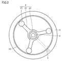
- FIG. 2 shows an example of the internal structure of the inner cylinder 9.
- the stopper assembly 2 includes three base portions 22, and the stopper portions 21 are respectively fixed on the outer end portions of the base portions 22. By rotating the lever 5, the three base portions 22 are simultaneously rotated, and accordingly, the three stopper portions 21 are also simultaneously rotated.
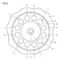
- FIG. 3 shows an example of the internal structure of the outer cylinder 1.
- the covering layer 24 continuously reaches the ring-shaped convex portion 16 from between the outer cylinder 1 and the diaphragm 4, covers the ring-shaped convex portion 16, and further covers the protruding portions 11 to 14. It reaches the center of the top plate of the outer cylinder 1. That is, the uneven structure on the inner surface of the upper surface plate of the outer cylinder 1 is covered with the integral covering layer 24.
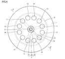
- four types of heights 11 to 14 are arranged at equal intervals. In the example of FIG. 3, three sets of four types of protrusions 11 to 14 having different heights are provided. Then, as shown in FIG.
- the three protruding portions 11 having the same height are arranged at positions corresponding to the three stopper portions 21.
- the protrusions 12 to 14 are arranged in the same manner. Thereby, the three stopper portions 21 can be rotated and simultaneously disposed at positions facing the three projecting portions 11 having the same height.
- FIG. 5 shows an enlarged view of the protruding portion 14 and the ring-shaped convex portion 16 and their vicinity.
- the ring-shaped convex portion 16 is joined to the inner surface 1 a located on the inner space 27 side of the outer cylinder 1.
- the ring-shaped convex part 16 is joined to the inner surface 1 a through the welded part 19.
- the welded portion 19 is formed at a boundary portion 20 c between the inner surface 1 a and the ring-shaped convex portion 16, and the covering layer 24 covers the welded portion 19.
- the welded portion 19 can be protected, and even if any defect occurs in the welded portion 19, it is possible to prevent the defect from reaching the internal space 27. Further, it is possible to suppress the metal powder or the like from diffusing into the internal space 27 from the welded portion 19.
- the protrusion 14 has a hollow structure.
- the protrusion part 14 has the side wall member 14a and the cover plate 14b which covers the upper end part of this side wall member 14a.
- the lower end of the side wall member 14 a is joined to the inner surface 1 a of the outer cylinder 1 via the welded portion 19, and the upper end of the side wall member 14 a is joined to the cover plate 14 b via the welded portion 19.
- An inner chamber 15a is provided inside the protruding portion 14 by the side wall member 14a and the cover plate 14b.
- the boundary portion 20a between the side wall member 14a and the cover plate 14b and the boundary portion 20b between the side wall member 14a and the inner surface 1a can be covered with the covering layer 24.
- the covering layer 24 it can.
- the coating layer 24 from the bottom of the diaphragm 4 to the flat region at the center of the upper surface plate of the outer cylinder 1, the sealing performance of the internal space 27 can be effectively improved.
- the covering layer 24 includes a side wall portion 24 a that covers the side wall member 14 a of the protruding portion 14, and an upper surface portion 24 b that covers the cover plate 14 b.
- the thickness t1 of the side wall portion 24a and the thickness t2 of the upper surface portion 24b may be the same, or may be different.
- the joint portion between the side wall member 14a and the inner surface 1a of the outer cylinder 1 and the joint portion between the side wall member 14a and the cover plate 14b can be reliably coated with the coating layer 24.
- FIG. 6 is a cross-sectional view showing a part of the air spring according to the second embodiment.
- the ring-shaped convex portion 16 has a hollow structure.
- Other configurations are the same as those in the first embodiment.
- the ring-shaped convex portion 16 includes a side wall member 16a and a cover plate 16b that covers the upper end portion of the side wall member 16a.
- the lower end of the side wall member 16 a is joined to the inner surface 1 a of the outer cylinder 1 via the welded portion 19, and the upper end of the side wall member 16 a is joined to the cover plate 16 b via the welded portion 19.
- An inner chamber 15b is provided inside the ring-shaped convex portion 16 by the side wall member 16a and the cover plate 16b.
- the coating layer 24 covers both the ring-shaped convex portion 16 having a hollow structure and the projecting portion 14 having a hollow structure. That is, in the second embodiment, the covering layer 24 covers a plurality of hollow structures.
- the covering layer 24 extends between the side wall member 16a of the ring-shaped convex part 16 and the diaphragm 4 from between the upper surface plate of the outer cylinder 1 and the diaphragm 4, covers the ring-shaped convex part 16, and the outer cylinder. 1 extends to the inner surface 1a of the projecting portion 14, reaches the side wall member 14a of the projecting portion 14, covers the projecting portion 14, and extends again to the inner surface 1a of the outer cylinder 1.
- FIG. 7 is a cross-sectional view showing a part of the air spring according to the third embodiment.
- a coating layer 24 is formed on the inner cylinder 9 side.
- the coating layer 24 may be formed only on the inner cylinder 9 side, but the coating layer 24 may be formed on both the inner cylinder 9 side and the outer cylinder 1.
- Other configurations are the same as those in the first embodiment.
- the stopper portion 21 has a side wall member 21a and a cover plate 21b that covers the upper end of the side wall member 21a.
- the lower end of the side wall member 21 a is joined to the inner surface 22 a of the base portion 22 in the stopper assembly 2 through the welded portion 19.
- the inner surface 22 a of the base portion 22 corresponds to the inner surface located on the inner space 27 side in the inner cylinder 9.
- the upper end of the side wall member 21 a is joined to the cover plate 21 b through the welded portion 19.
- An inner chamber 15c is provided inside the stopper portion 21 by the side wall member 21a and the cover plate 21b.
- the coating layer 24 covers the surface of the stopper portion 21 and extends on the inner surface 22 a of the base portion 22. Thereby, the boundary parts 20f and 20g in the stopper part 21 can be covered by the coating layer 24, and the same effect as the case of Embodiment 1 can be expected.
- the covering layer 24 also covers the boundary portion 20h between the ring portion 23 and the base portion 22 in the stopper assembly 2. That is, the coating layer 24 also covers the boundary portion 20 h between the inner surface of the inner cylinder 9 and the ring portion 23 that is an adjacent member adjacent to the inner surface.
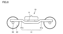
- FIG. 8 is a side view of the carriage.
- the carriage has an air spring 10, a carriage frame 81, an axle 82, and wheels 83.
- the carriage frame 81 includes a side beam 81a and a side beam 81b.
- the wheels 83 are attached to both ends of the axle 82.
- the axle 82 is attached to the bogie frame 81. More specifically, the bogie frame 81 is attached to the axle 82 by the side beams 81a and 81b being received and supported by the axle 82 via shaft springs (not shown).
- the air spring 10 is an air spring according to each of the above embodiments.
- the air spring 10 is attached to the carriage frame 81. More specifically, the laminated rubber 6 side of the air spring 10 is attached to the carriage frame 81.
Landscapes
- Engineering & Computer Science (AREA)
- General Engineering & Computer Science (AREA)
- Mechanical Engineering (AREA)
- Fluid-Damping Devices (AREA)
- Vibration Prevention Devices (AREA)
Abstract
空気ばねは、外筒と、外筒と組み合わされる内筒と、外筒と内筒とを連結し、外筒と内筒との間に内部空間を形成するダイヤフラムと、外筒と内筒の少なくとも一方における内部空間側に位置し、内部空間の一部を規定する第1要素と、第1要素と隣接し内部空間の一部を規定する第2要素と、第1要素と第2要素の間の境界部を覆う被覆層とを備える。
Description
本発明は空気ばね及び台車に関する。
従来から、圧縮空気の弾力性を利用した空気ばねは知られている。従来の空気ばねの一例が、例えば特開2000-035075号公報に記載されている。この文献に記載された空気ばねは、内筒4に設けられ隆起部8bを有するストッパ8と、隆起部8bに対応して外筒6に設けられた第1および第2被支持面6a,6bとを有する。
従来の空気ばねの他の例として、特開2012-017769号公報に記載された空気ばねもある。この公報に記載の空気ばねは、外筒1に設けられたゴム製の上ストップ部材5と、内筒2に設けられた下ストップ部材12とを有する。従来の空気ばねのさらに他の例として、特開2012-145135号公報に記載された空気ばねを挙げることができる。この空気ばねは、上部材3に設けられたゴム製の上ストッパ12と、下部材4に設けられた下ストッパ16とを有する。
本発明に係る空気ばねは、該空気ばねの内部における要素間の境界部を覆う被覆層を備える。ここで、本願明細書では、「境界部」には、要素同士を溶接、接着等により接合した接合部、要素同士を直接または間接的に固定した場合の当該要素間の接触部(一部接触の場合も含む)および間隙部、並びに隣り合う要素間の接触部(一部接触の場合も含む)および間隙部等の様々な態様が包含される。
本発明の一態様である空気ばねは、外筒と、この外筒と組み合わされる内筒と、外筒と内筒とを連結し、外筒と内筒との間に内部空間を形成するダイヤフラムとを備える。この空気ばねは、外筒と内筒の少なくとも一方における内部空間側に位置し、内部空間の一部を規定する第1要素と、第1要素と隣接し内部空間の一部を規定する第2要素と、第1要素と第2要素との間の境界部を覆う被覆層とを備える。ここで、上記「内部空間の一部を規定する」とは、本願明細書では、内部空間に露出して内部空間の一部を直接規定する場合のみならず、内部空間に沿って延在し、他の要素と共に内部空間の一部を間接的に規定する場合も含まれる。また、上記「隣接」には、隣り合う2つの要素が、互いに接触する場合と、部分的に接触する場合と、非接触で近接する場合のいずれも含まれる。
[本開示が解決しようとする課題]
以下、図1~図7を用いて、本発明の実施の形態における空気ばねを説明するが、その前に、上述した特許文献1(特開2000-035075号公報)、特許文献2(特開2012-017769号公報)および特許文献3(特開2012-145135号公報)に記載の空気ばねが包含する課題について説明する。
以下、図1~図7を用いて、本発明の実施の形態における空気ばねを説明するが、その前に、上述した特許文献1(特開2000-035075号公報)、特許文献2(特開2012-017769号公報)および特許文献3(特開2012-145135号公報)に記載の空気ばねが包含する課題について説明する。
まず、上記特許文献1に記載の空気ばねについて説明する。この空気ばねでは、第1被支持面(6a)と第2被支持面(6b)との境界部が、空気ばねの内部空間に露出している。そのため、この境界部に損傷等の不具合が生じた場合に、空気ばねの内部空間に直接その不具合の影響(例えば、シールリング部でのエア漏れや、摩耗粉による配管詰まり等)が及んでしまう。
特許文献2に記載の空気ばね(A)においても、図3等に示される例では、上ストップ部材5と主体(1A)との境界部は、空気ばね(A)の内部空間に露出している。そのため、特許文献1の場合と同様に、上記境界部に損傷等の不具合が生じた場合に、空気ばねの内部空間に直接その不具合の影響が及ぶという問題が生じる。
特許文献3に記載の空気ばね(1)でも、上面板(9)と上ストッパ(12)との境界部が、空気ばね(1)の内部空間に露出している。そのため、特許文献1,2の場合と同様に、境界部に損傷等の不具合が生じた場合に、空気ばねの内部空間に直接その不具合の影響が及ぶという問題がある。
[本開示の効果]
本実施の形態の空気ばねは、上記のような特許文献1~3に記載の空気ばねにおける課題を解決可能である。本実施の形態の空気ばねは、内部空間の一部を規定する要素間の境界部を覆う被覆層を備えているので、この境界部に損傷等の何らかの不具合が生じた場合においても、当該不具合の影響が内部空間に直接及ぶのを回避することができる。
本実施の形態の空気ばねは、上記のような特許文献1~3に記載の空気ばねにおける課題を解決可能である。本実施の形態の空気ばねは、内部空間の一部を規定する要素間の境界部を覆う被覆層を備えているので、この境界部に損傷等の何らかの不具合が生じた場合においても、当該不具合の影響が内部空間に直接及ぶのを回避することができる。
[本願発明の実施形態の説明]
最初に本願発明の実施形態の概要を列挙して説明する。
最初に本願発明の実施形態の概要を列挙して説明する。
(1)本発明の一態様に係る空気ばねは、外筒と、外筒と組み合わされる内筒と、外筒と内筒とを連結し、外筒と内筒との間に内部空間を形成するダイヤフラムとを備える。この空気ばねは、内部空間に、第1要素と第2要素とを備える。第1要素は、外筒と内筒の少なくとも一方における内部空間側に位置し、内部空間の一部を規定する。第2要素は、第1要素と隣接し、内部空間の一部を規定する。上記空気ばねは、第1要素と第2要素との間の境界部を覆う被覆層を備える。
(2)上記(1)に係る空気ばねにおいて、外筒と内筒の少なくとも一方は、内部空間側に位置する内側表面と、内側表面に接合された接合部材とを含んでもよい。この場合、上記第1要素は、内側表面を含み、上記第2要素は、接合部材を含み、上記境界部は、接合部材と内側表面との接合部を含むものであってもよい。
(3)上記(1)に係る空気ばねにおいて、外筒と内筒の少なくとも一方は、内部空間側に位置する内側表面と、内側表面に接合され内部室を有する突出部とを含んでもよい。この場合、上記第1要素は、内側表面を含み、上記第2要素は、突出部を含み、上記境界部は、突出部と内側表面との接合部を含むものであってもよい。
(4)上記(3)に係る空気ばねにおいて、突出部は、内側表面と接合される側壁部材と、この側壁部材と接合されるカバープレートとを有してもよい。また、複数の接合部が設けられてもよい。複数の接合部は、側壁部材と内側表面との第1接合部と、側壁部材とカバープレートとの第2接合部とを含んでもよい。この場合、被覆層は、第1接合部上から第2接合部上に延在する。
(5)上記(4)に係る空気ばねにおいて、側壁部材上に位置する被覆層の厚みは、カバープレート上に位置する被覆層の厚みと等しくてもよく、カバープレート上に位置する被覆層の厚みより大きくてもよい。
(6)上記(4)に係る空気ばねにおいて、カバープレート上に位置する被覆層の厚みは、側壁部材上に位置する被覆層の厚みより大きくてもよい。
(7)上記(1)に係る空気ばねにおいて、外筒は、外筒の内側表面に接合されダイヤフラムの一端を受ける受け部と、この受け部と間隔をあけて外筒の内側表面に接合され外筒の変位を制限可能な突出部とを有してもよい。この場合、上記第1要素は、外筒の内側表面を含み、上記第2要素は、受け部と突出部とを含み、被覆層は、受け部と外筒の内側表面との接合部上から、外筒の内側表面と突出部との接合部上に延在してもよい。
(8)上記(2)~(8)に係る空気ばねにおいて、上記被覆層は、受け部とダイヤフラムの一端との間にまで延在してもよい。
(9)上記(2)~(8)に係る空気ばねにおいて、上記接合部は溶接部を含んでもよい。
(10)上記(1)に係る空気ばねにおいて、外筒と内筒の少なくとも一方は、内部空間側に位置する内側表面と、内側表面に隣接する隣接部材とを含んでもよい。この場合、上記第1要素は、内側表面を含み、上記第2要素は、隣接部材を含み、上記境界部は、内側表面と隣接部材との境界部を含むものであってもよい。
(11)上記(1)~(10)に係る空気ばねにおいて、上記被覆層は、境界部上に第1の厚みを有する第1の部分と、境界部以外の部分上に第1の厚みよりも小さい第2の厚みを有する第2の部分とを含むものであってもよい。
(12)上記(1)~(11)に係る空気ばねにおいて、上記被覆層は、樹脂、ゴム、プラスチック、エラストマーからなる群から選ばれる少なくとも1つの材質で構成されてもよい。
(13)上記(1)~(12)に係る空気ばねにおいて、上記ダイヤフラムと上記被覆層は、異なる材質で構成されてもよい。
(14)上記(1)~(13)に係る空気ばねにおいて、上記被覆層の機械的特性を、上記ダイヤフラムの機械的特性と異ならせてもよい。
(15)本開示の一態様に係る台車は、(1)~(14)の空気ばねを備えている。
[本願発明の実施形態の詳細]
次に本願発明の実施形態の詳細について説明する。本実施の形態の空気ばねは、懸架装置、防振装置、車高調整装置等の様々な用途に使用可能であるが、例えば鉄道車両に用いる場合、車両と台車部(台車および車輪)の間に装着され、車輪から車両に伝わる振動を軽減することができる。
[本願発明の実施形態の詳細]
次に本願発明の実施形態の詳細について説明する。本実施の形態の空気ばねは、懸架装置、防振装置、車高調整装置等の様々な用途に使用可能であるが、例えば鉄道車両に用いる場合、車両と台車部(台車および車輪)の間に装着され、車輪から車両に伝わる振動を軽減することができる。
また、本実施の形態の空気ばねは、セルフシール方式の空気ばねであり、外筒と、内筒と、ダイヤフラムとを備える。外筒は、概ね円筒形状を有し、円形の上面板と、この上面板の周縁部から立ち上がる環状の周壁部とを有する。内筒は、外筒と組み合わされ、概ね円筒形状を有する。内筒は、外筒の周壁部の内側に配置され、円形の下面板と、この下面板から立ち上がる環状の壁部とを有する。外筒および内筒は、金属や繊維強化プラスチック(Fiberglass Reinforced Plastics)等の剛性を有する素材で作製可能である。ダイヤフラムは、外筒と内筒とを連結し、外筒と内筒との間に内部空間を形成する。ダイヤフラムの一端は、外筒の一部(例えば、外筒の上面板に立設された受け部)に当接され、ダイヤフラムの他端は、内筒の一部(例えば、内筒の下面板に立設された上記壁部)に当接される。ダイヤフラムは、変形可能な材質、例えばゴム、エラストマー等の弾性材料で作製することができる。空気ばねの内部空間は密閉空間であり、この内部空間には加圧空気が封入される。
本実施の形態の空気ばねは、上記内筒上で回動可能となるように内部空間に配置され、外筒が必要以上に内筒側に移動するのを抑制可能なストッパアセンブリと、このストッパアセンブリを内筒上で回動させる回動機構をも備える。ストッパアセンブリは、手動により駆動可能であってもよく、動力源からの動力により駆動可能であってもよい。
本実施の形態の空気ばねの内部空間には、上述のストッパアセンブリを含む様々な要素が配置される。これらの要素の中には、空気ばねの内部空間の一部を直接または間接的に規定するものがある。本実施の形態では、隣り合う要素間の境界部上に、被覆層を形成する。被覆層の材質としては、様々な材質が考えられるが、弾性変形可能な材質を採用することができる。具体的には、被覆層は、例えば、樹脂、ゴム、プラスチック、あるいはエラストマーの単層、これらを組合せた積層構造で構成することができる。また、被覆層の材質として、成形可能な材質を選択するのが好ましい。それにより、被覆層を容易に形成することができる。
(実施の形態1)
図1~図5を用いて、本発明の実施の形態1について説明する。図1は、本実施の形態1における空気ばねの断面図である。図1に示すように、空気ばね10は、外筒1と、内筒9と、ダイヤフラム4とを備える。外筒1と、ダイヤフラム4と、内筒9とにより、空気ばね10の内部に実質的に密閉された内部空間27が形成される。
(実施の形態1)
図1~図5を用いて、本発明の実施の形態1について説明する。図1は、本実施の形態1における空気ばねの断面図である。図1に示すように、空気ばね10は、外筒1と、内筒9と、ダイヤフラム4とを備える。外筒1と、ダイヤフラム4と、内筒9とにより、空気ばね10の内部に実質的に密閉された内部空間27が形成される。
外筒1は、中央部に上面板と、周縁部に側壁部とを有する。上面板は、この上面板から突出する複数の突出部11~14と、上面板から立ち上がり、突出部11~14よりも外側に位置するリング状凸部16とを備える。リング状凸部16は、環状の形状を有し、ダイヤフラムの一端を受ける受け部としての機能を有する。上面板の中央部に穴部を設け、この穴部に連結部17を装着する。側壁部とダイヤフラム4との間に、リングガイド29を形成する。突出部11~14は、円筒状の形状を有し、図1に示すように、それぞれ異なる高さを有する。突出部11~14は、中空と中実のいずれであってもよい。また、突出部11~14の一部を中空とし、残りを中実としてもよい。
本実施の形態1では、突出部11~14と上面板との境界部と、リング状凸部16と上面板との境界部とを覆うように被覆層24を設けている。それにより、これらの境界部に何らかの不具合が生じたとしても、その不具合が直接内部空間27に及ぶのを回避することができる。例えば、金属製の要素間の境界部を被覆層24で覆った場合には、何らかの要因で境界部において発生し得る損傷で境界部の気密性が損なわれたり、金属粉等が内部空間27内に拡散するのを抑制することができる。
被覆層24の材質としては、本実施の形態1では、ゴムを採用する。被覆層24は、単層で構成してもよいが、複数層で構成してもよい。被覆層24は、ダイヤフラム4と同じ材質あるいは同種の材質で構成することもできるが、ダイヤフラム4と異なる材質で構成してもよい。例えば、被覆層24の硬度等の機械的特性を、ダイヤフラム4の硬度等の機械的特性と異ならせることが考えられる。それにより、被覆層24自体の機能を維持しながら、被覆層24とダイヤフラム4とを接触させた場合の両者の密着性や摩耗の度合をも適切に調整することができる。
内筒9は、図1に示すように、中央部に穴部と、この穴部の周囲に上面部を有する下面板と、この下面板から立ち上がるフランジ部18と、下面板の上面部に配置されるストッパアセンブリ2とを含む。ストッパアセンブリ2は、円筒状の形状を有する複数のストッパ部21と、ストッパ部21が載置されるベース部22と、下面板の中央部の穴部に挿着されるリング部23とを有する。ストッパ部21は、外筒1が内筒9側へ所定量以上移動するのを抑制する変位規制機能を有する。
図1に示すように、ダイヤフラム4は、外筒1と内筒9とを連結し、これらの間に上述の内部空間27を形成する。ダイヤフラム4の材質も、本実施の形態1では、ゴムを採用する。ダイヤフラム4の一端側の部分は、外筒1の側壁部と上面板とに沿って延在する。ダイヤフラム4の一端は、外筒1のリング状凸部16を覆う被覆層24に当接される。ダイヤフラム4の他端側の部分は、内筒9の周縁部上に載置される。ダイヤフラム4の他端は、内筒9のフランジ部18に当接される。
図1に示すように、本実施の形態1では、リング状凸部16とダイヤフラム4との間に被覆層24を形成している。このとき、ダイヤフラム4と被覆層24の材質等を適切に選択することにより、上述のように、ダイヤフラム4と被覆層24との良好な密着性を得ることができる。図1の例では、被覆層24は、リング状凸部16とダイヤフラム4との間に延在し、さらに外筒1の側壁部上にまで延在し、リングガイド29に達している。ダイヤフラム4と内筒9の周縁部との間には、ゴム座26が配置される。
内筒9の下には、底板8が配置される。底板8は、中央部に筒状部を有しており、この筒状部は、ストッパアセンブリ2のリング部23内に挿着される。内筒9には、ネジ穴30が設けられ、底板8に挿通したボルト28をネジ穴30に螺着することで、内筒9に底板8を固定することができる。内筒9と底板8間に、ストッパアセンブリ2を回動操作するためのレバー5が配設される。レバー5の一端は、ネジ25によりリング部23に固定され、レバー5の他端には、手でレバー5を回動操作可能となるようにハンドル7が装着される。底板8の下には、積層ゴム6が配置される。
図2に、内筒9の内部構造例を示す。図2に示すように、ストッパアセンブリ2は、3つのベース部22を備え、各ベース部22の外側端部上にストッパ部21がそれぞれ固定される。レバー5を回動操作することにより、3つのベース部22が同時に回動され、それに伴い3つのストッパ部21も同時に回動されることとなる。
図3に、外筒1の内部構造例を示す。図3に示すように、被覆層24は、外筒1とダイヤフラム4との間から連続的にリング状凸部16に達し、リング状凸部16を覆い、さらに突出部11~14を覆い、外筒1の上面板の中央部にまで達している。つまり、外筒1の上面板の内側表面における凹凸構造が、一体の被覆層24で覆われている。図3に示すように、4種類の高さの突出部11~14が等間隔で配置される。図3の例では、それぞれ異なる高さを有する4種類の突出部11~14が3セット設けられている。そして、図4に示すように、同じ高さを有する3つの突出部11が、3つのストッパ部21に対応する位置に配置される。突出部12~14も同様に配置される。それにより、3つのストッパ部21を回動させて、同時に同じ高さを有する3つの突出部11と対向する位置に配置することができる。
図5に、突出部14およびリング状凸部16とそれらの近傍の拡大図を示す。図5に示すように、外筒1の内部空間27側に位置する内側表面1aに、リング状凸部16を接合している。リング状凸部16は、溶接部19を介して内側表面1aに接合されている。溶接部19は、内側表面1aとリング状凸部16との境界部20cに形成され、被覆層24は、溶接部19を覆っている。それにより、溶接部19を保護することができ、また溶接部19に何らかの不具合が生じた場合でも、その不具合が内部空間27に及ぶのを回避することができる。さらに、溶接部19から金属粉等が内部空間27に拡散するのを抑制することもできる。
図5に示すように、突出部14は中空構造を有する。突出部14は、側壁部材14aと、この側壁部材14aの上端部を覆うカバープレート14bとを有する。側壁部材14aの下端は、溶接部19を介して外筒1の内側表面1aに接合され、側壁部材14aの上端は、溶接部19を介してカバープレート14bに接合されている。側壁部材14aとカバープレート14bにより、突出部14の内部に内部室15aが設けられる。このとき、突出部14を被覆層24で覆うことにより、側壁部材14aとカバープレート14bとの境界部20aと、側壁部材14aと内側表面1aとの境界部20bとを被覆層24で覆うことができる。それにより、内部空間27内の加圧空気が境界部20a,20bを介して内部室15a内に漏れるのを抑制することができ、内部空間27の密閉性を向上することができる。特に、ダイヤフラム4下から、外筒1の上面板の中央部の平坦領域まで連続的に被覆層24を形成することにより、効果的に内部空間27の密閉性を向上することができる。
図5に示すように、被覆層24は、突出部14の側壁部材14aを覆う側壁部24aと、カバープレート14bを覆う上面部24bとを有する。側壁部24aの厚みt1と、上面部24bの厚みt2は、同一の厚みとしてもよいが、異ならせてもよい。側壁部24aの厚みt1を、上面部24bの厚みt2以上とした場合には、側壁部材14aと、外筒1の内側表面1aとの接合部と、側壁部材14aとカバープレート14bとの接合部とを、被覆層24により信頼性高く被覆することができる。他方、上面部24bの厚みt2を側壁部24aの厚みt1よりも大きくした場合には、突出部14が内筒9のストッパ部21と接触した場合の互いの損傷を効果的に軽減することができる。
(実施の形態2)
次に、図6を用いて、本発明の実施の形態2について説明する。図6は、本実施の形態2における空気ばねの一部を示す断面図である。図6に示すように、本実施の形態2では、リング状凸部16を中空構造としている。それ以外の構成は、実施の形態1の場合と同様である。
(実施の形態2)
次に、図6を用いて、本発明の実施の形態2について説明する。図6は、本実施の形態2における空気ばねの一部を示す断面図である。図6に示すように、本実施の形態2では、リング状凸部16を中空構造としている。それ以外の構成は、実施の形態1の場合と同様である。
図6に示すように、リング状凸部16は、側壁部材16aと、この側壁部材16aの上端部を覆うカバープレート16bとを有する。側壁部材16aの下端は、溶接部19を介して外筒1の内側表面1aに接合され、側壁部材16aの上端は、溶接部19を介してカバープレート16bに接合されている。側壁部材16aとカバープレート16bにより、リング状凸部16の内部に内部室15bが設けられる。
図6に示すように、被覆層24は、中空構造のリング状凸部16と、中空構造の突出部14との双方を覆っている。つまり、本実施の形態2では、被覆層24は、複数の中空構造を覆っている。被覆層24は、外筒1の上面板とダイヤフラム4との間から、リング状凸部16の側壁部材16aとダイヤフラム4との間に延在し、リング状凸部16を覆い、かつ外筒1の内側表面1a上に延在し、突出部14の側壁部材14a上に達し、さらに突出部14を覆い、再び外筒1の内側表面1a上に延在している。本実施の形態2でも、突出部14における境界部20a,20bと、リング状凸部16における境界部20d,20eとを被覆層24で覆うことができ、実施の形態1の場合と同様の効果を期待できる。
(実施の形態3)
次に、図7を用いて、本発明の実施の形態3について説明する。図7は、本実施の形態3における空気ばねの一部を示す断面図である。図7に示すように、本実施の形態3では、内筒9側に被覆層24を形成する。被覆層24は、内筒9側のみに形成してもよいが、内筒9側と外筒1の双方に被覆層24を形成してもよい。それ以外の構成は、実施の形態1の場合と同様である。
(実施の形態3)
次に、図7を用いて、本発明の実施の形態3について説明する。図7は、本実施の形態3における空気ばねの一部を示す断面図である。図7に示すように、本実施の形態3では、内筒9側に被覆層24を形成する。被覆層24は、内筒9側のみに形成してもよいが、内筒9側と外筒1の双方に被覆層24を形成してもよい。それ以外の構成は、実施の形態1の場合と同様である。
図7に示すように、ストッパ部21は、側壁部材21aと、この側壁部材21aの上端を覆うカバープレート21bとを有する。側壁部材21aの下端は、溶接部19を介して、ストッパアセンブリ2におけるベース部22の内側表面22aに接合される。このベース部22の内側表面22aが、内筒9における内部空間27側に位置する内側表面に対応する。側壁部材21aの上端は、溶接部19を介してカバープレート21bに接合されている。側壁部材21aとカバープレート21bにより、ストッパ部21の内部に内部室15cが設けられる。本実施の形態3では、被覆層24は、ストッパ部21の表面を覆い、ベース部22の内側表面22a上に延在している。それにより、被覆層24によって、ストッパ部21における境界部20f,20gを覆うことができ、実施の形態1の場合と同様の効果を期待できる。
本実施の形態3では、被覆層24は、ストッパアセンブリ2におけるリング部23と、ベース部22との境界部20hをも覆っている。つまり、被覆層24は、内筒9の内側表面と、この内側表面に隣接する隣接部材であるリング部23との境界部20hをも覆っている。それにより、境界部20hに何らかの不具合が生じた場合に、その不具合が内部空間27に及ぶのを回避することができる。
以下に、本発明の実施形態に係る台車の構成について説明する。
図8は、台車の側面図である。図8に示すように、台車は、空気ばね10と、台車枠81と、車軸82と、車輪83とを有する。台車枠81は、側梁81aと側梁81bとを有する。車輪83は、車軸82の両端に取り付けられる。車軸82は、台車枠81に取り付けられる。より具体的には、台車枠81は、側梁81a及び側梁81bが軸ばね(図示せず)を介して車軸82に受け支えられることにより、車軸82に取り付けられる。空気ばね10は、上記の各実施形態に係る空気ばねである。空気ばね10は、台車枠81に取り付けられる。より具体的には、空気ばね10の積層ゴム6の側が台車枠81に取り付けられる。
図8は、台車の側面図である。図8に示すように、台車は、空気ばね10と、台車枠81と、車軸82と、車輪83とを有する。台車枠81は、側梁81aと側梁81bとを有する。車輪83は、車軸82の両端に取り付けられる。車軸82は、台車枠81に取り付けられる。より具体的には、台車枠81は、側梁81a及び側梁81bが軸ばね(図示せず)を介して車軸82に受け支えられることにより、車軸82に取り付けられる。空気ばね10は、上記の各実施形態に係る空気ばねである。空気ばね10は、台車枠81に取り付けられる。より具体的には、空気ばね10の積層ゴム6の側が台車枠81に取り付けられる。
以上のように本発明の実施の形態について説明を行なったが、各実施の形態の構成を適宜組合せることも当初から予定している。また、今回開示した実施の形態はすべての点での例示であって制限的なものではないと考えられるべきである。本発明の範囲は請求の範囲によって示され、請求の範囲と均等の意味および範囲内でのすべての変更が含まれる。
1 外筒、1a,22a 内側表面、2 ストッパアセンブリ、4 ダイヤフラム、5 レバー、6 積層ゴム、7 ハンドル、8 底板、9 内筒、10 空気ばね、11、12、13、14 突出部、14a、16a、21a 側壁部材、14b、16b、21b カバープレート、15a,15b,15c 内部室、16 リング状凸部、17 連結部、18 フランジ部、19 溶接部、20a,20b,20c,20d,20e,20f,20g,20h 境界部、21 ストッパ部、22 ベース部、23 リング部、24 被覆層、24a 側壁部、24b 上面部、25 ネジ、26 ゴム座、27 内部空間、28 ボルト、29 リングガイド、30 ネジ穴、81 台車枠、82 車軸、83 車輪。
Claims (15)
- 外筒と、
前記外筒と組み合わされる内筒と、
前記外筒と前記内筒とを連結し、前記外筒と前記内筒との間に内部空間を形成するダイヤフラムと、
前記外筒と前記内筒の少なくとも一方における前記内部空間側に位置し、前記内部空間の一部を規定する第1要素と、
前記第1要素に隣接し前記内部空間の一部を規定する第2要素と、
前記第1要素と前記第2要素との間の境界部を覆う被覆層とを備えた空気ばね。 - 前記外筒と前記内筒の少なくとも一方は、前記内部空間側に位置する内側表面と、前記内側表面に接合された接合部材とを含み、
前記第1要素は、前記内側表面を含み、
前記第2要素は、前記接合部材を含み、
前記境界部は、前記接合部材と前記内側表面との接合部を含む、請求項1に記載の空気ばね。 - 前記外筒と前記内筒の少なくとも一方は、前記内部空間側に位置する内側表面と、前記内側表面に接合され内部室を有する突出部とを含み、
前記第1要素は、前記内側表面を含み、
前記第2要素は、前記突出部を含み、
前記境界部は、前記突出部と前記内側表面との接合部を含む、請求項1に記載の空気ばね。 - 前記突出部は、前記内側表面と接合される側壁部材と、前記側壁部材と接合されるカバープレートとを有し、
複数の前記接合部が設けられ、
前記複数の接合部は、前記側壁部材と前記内側表面との第1接合部と、前記側壁部材と前記カバープレートとの第2接合部とを含み、
前記被覆層は、前記第1接合部上から前記第2接合部上に延在する、請求項3に記載の空気ばね。 - 前記側壁部材上に位置する前記被覆層の厚みは、前記カバープレート上に位置する前記被覆層の厚み以上である、請求項4に記載の空気ばね。
- 前記カバープレート上に位置する前記被覆層の厚みは、前記側壁部材上に位置する前記被覆層の厚みよりも大きい、請求項4に記載の空気ばね。
- 前記外筒は、前記外筒の内側表面に接合され前記ダイヤフラムの一端を受ける受け部と、前記受け部と間隔をあけて前記外筒の内側表面に接合され前記外筒の変位を制限可能な突出部とを有し、
前記第1要素は、前記外筒の内側表面を含み、
前記第2要素は、前記受け部と前記突出部とを含み、
前記被覆層は、前記受け部と前記外筒の内側表面との接合部上から、前記外筒の内側表面と前記突出部との接合部上に延在する、請求項1に記載の空気ばね。 - 前記被覆層は、前記受け部と前記ダイヤフラムの一端との間にまで延在する、請求項7に記載の空気ばね。
- 前記接合部は溶接部を含む、請求項2から請求項8のいずれか1項に記載の空気ばね。
- 前記外筒と前記内筒の少なくとも一方は、前記内部空間側に位置する内側表面と、前記内側表面に隣接する隣接部材とを含み、
前記第1要素は、前記内側表面を含み、
前記第2要素は、前記隣接部材を含み、
前記境界部は、前記内側表面と前記隣接部材との境界部を含む、請求項1に記載の空気ばね。 - 前記被覆層は、前記境界部上に第1の厚みを有する第1の部分と、前記境界部以外の部分上に前記第1の厚みよりも小さい第2の厚みを有する第2の部分とを含む、請求項1から請求項10のいずれか1項に記載の空気ばね。
- 前記被覆層は、樹脂、ゴム、プラスチック、エラストマーからなる群から選ばれる少なくとも1つの材質で構成される、請求項1から請求項11のいずれか1項に記載の空気ばね。
- 前記ダイヤフラムと前記被覆層は、異なる材質で構成される、請求項1から請求項12のいずれか1項に記載の空気ばね。
- 前記被覆層の機械的特性を、前記ダイヤフラムの機械的特性と異ならせた、請求項1から請求項13のいずれか1項に記載の空気ばね。
- 請求項1~14のいずれか1項に記載の空気ばねを備える、台車。
Priority Applications (6)
| Application Number | Priority Date | Filing Date | Title |
|---|---|---|---|
| SG11201903360RA SG11201903360RA (en) | 2016-10-17 | 2016-10-17 | Air spring and bogie |
| JP2017511970A JP6946177B2 (ja) | 2016-10-17 | 2016-10-17 | 空気ばね及び台車 |
| PCT/JP2016/080698 WO2018073863A1 (ja) | 2016-10-17 | 2016-10-17 | 空気ばね及び台車 |
| CN201680090142.9A CN109844358B (zh) | 2016-10-17 | 2016-10-17 | 空气弹簧和转向架 |
| US15/528,551 US10597050B2 (en) | 2016-10-17 | 2016-10-17 | Air spring and bogie |
| TW106135480A TWI756281B (zh) | 2016-10-17 | 2017-10-17 | 空氣彈簧及台車 |
Applications Claiming Priority (1)
| Application Number | Priority Date | Filing Date | Title |
|---|---|---|---|
| PCT/JP2016/080698 WO2018073863A1 (ja) | 2016-10-17 | 2016-10-17 | 空気ばね及び台車 |
Publications (1)
| Publication Number | Publication Date |
|---|---|
| WO2018073863A1 true WO2018073863A1 (ja) | 2018-04-26 |
Family
ID=62018322
Family Applications (1)
| Application Number | Title | Priority Date | Filing Date |
|---|---|---|---|
| PCT/JP2016/080698 Ceased WO2018073863A1 (ja) | 2016-10-17 | 2016-10-17 | 空気ばね及び台車 |
Country Status (6)
| Country | Link |
|---|---|
| US (1) | US10597050B2 (ja) |
| JP (1) | JP6946177B2 (ja) |
| CN (1) | CN109844358B (ja) |
| SG (1) | SG11201903360RA (ja) |
| TW (1) | TWI756281B (ja) |
| WO (1) | WO2018073863A1 (ja) |
Families Citing this family (2)
| Publication number | Priority date | Publication date | Assignee | Title |
|---|---|---|---|---|
| US10449979B2 (en) * | 2016-10-17 | 2019-10-22 | Sumitomo Electric Industries, Ltd. | Air spring and bogie |
| DE102022129748A1 (de) * | 2022-11-10 | 2024-05-16 | Bayerische Motoren Werke Aktiengesellschaft | Luftfeder für ein Fahrzeug, insbesondere für ein Kraftfahrzeug, sowie Baukastensystem |
Citations (2)
| Publication number | Priority date | Publication date | Assignee | Title |
|---|---|---|---|---|
| JP2012017769A (ja) * | 2010-07-06 | 2012-01-26 | Toyo Tire & Rubber Co Ltd | ストッパ付空気ばね |
| WO2014194008A1 (en) * | 2013-05-28 | 2014-12-04 | Firestone Industrial Products Company, Llc | End member assemblies and travel-restraint assemblies as well as gas spring assemblies including same |
Family Cites Families (13)
| Publication number | Priority date | Publication date | Assignee | Title |
|---|---|---|---|---|
| US4721292A (en) * | 1986-07-24 | 1988-01-26 | Tokai Rubber Industries, Ltd. | Fluid-filled elastic mounting structure |
| JP3017972B2 (ja) * | 1998-07-16 | 2000-03-13 | 住友電気工業株式会社 | 空気ばね |
| JP5069974B2 (ja) * | 2007-08-24 | 2012-11-07 | 東洋ゴム工業株式会社 | 車両用懸架装置 |
| WO2009107679A1 (ja) * | 2008-02-25 | 2009-09-03 | 株式会社ブリヂストン | 空気ばね装置 |
| US8540220B2 (en) * | 2009-07-07 | 2013-09-24 | Sumitomo Electric Industries, Ltd. | Air spring for vehicle and railway truck for vehicle |
| JP5524711B2 (ja) | 2010-05-25 | 2014-06-18 | 東洋ゴム工業株式会社 | 空気ばね |
| JP5504075B2 (ja) | 2010-07-06 | 2014-05-28 | 東洋ゴム工業株式会社 | ストッパ付空気ばね |
| JP5654294B2 (ja) * | 2010-09-06 | 2015-01-14 | 東洋ゴム工業株式会社 | 空気ばね |
| JP5803930B2 (ja) * | 2010-10-25 | 2015-11-04 | 住友電気工業株式会社 | 車両用空気ばねとそれを用いた台車 |
| JP5670760B2 (ja) | 2011-01-07 | 2015-02-18 | 東洋ゴム工業株式会社 | 空気ばね |
| JP5939065B2 (ja) * | 2012-07-19 | 2016-06-22 | 住友電気工業株式会社 | 空気ばね |
| JP6283467B2 (ja) * | 2013-02-22 | 2018-02-21 | 東洋ゴム工業株式会社 | 空気ばね用ダイヤフラム及び空気ばね |
| US10087628B2 (en) * | 2015-07-05 | 2018-10-02 | Constantine Shuhaibar | Structural system and method using monolithic beams having improved strength |
-
2016
- 2016-10-17 SG SG11201903360RA patent/SG11201903360RA/en unknown
- 2016-10-17 CN CN201680090142.9A patent/CN109844358B/zh active Active
- 2016-10-17 US US15/528,551 patent/US10597050B2/en active Active
- 2016-10-17 JP JP2017511970A patent/JP6946177B2/ja active Active
- 2016-10-17 WO PCT/JP2016/080698 patent/WO2018073863A1/ja not_active Ceased
-
2017
- 2017-10-17 TW TW106135480A patent/TWI756281B/zh active
Patent Citations (2)
| Publication number | Priority date | Publication date | Assignee | Title |
|---|---|---|---|---|
| JP2012017769A (ja) * | 2010-07-06 | 2012-01-26 | Toyo Tire & Rubber Co Ltd | ストッパ付空気ばね |
| WO2014194008A1 (en) * | 2013-05-28 | 2014-12-04 | Firestone Industrial Products Company, Llc | End member assemblies and travel-restraint assemblies as well as gas spring assemblies including same |
Also Published As
| Publication number | Publication date |
|---|---|
| US20190084594A1 (en) | 2019-03-21 |
| US10597050B2 (en) | 2020-03-24 |
| JP6946177B2 (ja) | 2021-10-06 |
| TWI756281B (zh) | 2022-03-01 |
| CN109844358B (zh) | 2021-11-09 |
| CN109844358A (zh) | 2019-06-04 |
| TW201819795A (zh) | 2018-06-01 |
| JPWO2018073863A1 (ja) | 2019-08-08 |
| SG11201903360RA (en) | 2019-05-30 |
Similar Documents
| Publication | Publication Date | Title |
|---|---|---|
| KR20100084152A (ko) | 스프링 조립체 | |
| JP2005505733A (ja) | 振動減衰式ゴム軸受 | |
| WO2011122424A1 (ja) | ダイアフラム | |
| JPWO2018073863A1 (ja) | 空気ばね及び台車 | |
| KR20110063521A (ko) | 액체 봉입식 방진 장치 | |
| CN103847786A (zh) | 用于车辆的双壁圆顶密封件 | |
| JP6637380B2 (ja) | 空気ばね装置 | |
| WO2012115183A1 (ja) | 空気ばね装置 | |
| WO2012077364A1 (ja) | 空気ばね及びその製造方法 | |
| WO2018181210A1 (ja) | 密封装置 | |
| US10253840B2 (en) | Cylinder apparatus | |
| JP5060196B2 (ja) | ダイヤフラム | |
| JP4504955B2 (ja) | プラグ孔用ガスケット | |
| JP5922378B2 (ja) | 空気ばね | |
| JP4600649B2 (ja) | スリーブ | |
| JP6946179B2 (ja) | 空気ばね及び台車 | |
| JP6875123B2 (ja) | 空気ばね及び空気ばね用ゴム座 | |
| WO2019181461A1 (ja) | 密封装置 | |
| JP4113192B2 (ja) | 液封入式防振装置 | |
| JP6572104B2 (ja) | 液封入式防振装置 | |
| JP2022065487A (ja) | 車体パネルの接着構造 | |
| JP6402593B2 (ja) | 遮音シール付き密封装置 | |
| JP2024000660A (ja) | 防振装置 | |
| JP2021032367A (ja) | 液封ブッシュ | |
| JP2019218964A (ja) | 液封ブッシュ |
Legal Events
| Date | Code | Title | Description |
|---|---|---|---|
| WWE | Wipo information: entry into national phase |
Ref document number: 2017511970 Country of ref document: JP |
|
| 121 | Ep: the epo has been informed by wipo that ep was designated in this application |
Ref document number: 16919022 Country of ref document: EP Kind code of ref document: A1 |
|
| NENP | Non-entry into the national phase |
Ref country code: DE |
|
| 122 | Ep: pct application non-entry in european phase |
Ref document number: 16919022 Country of ref document: EP Kind code of ref document: A1 |