WO2018070294A1 - 自動変速機および自動変速機の制御方法 - Google Patents
自動変速機および自動変速機の制御方法 Download PDFInfo
- Publication number
- WO2018070294A1 WO2018070294A1 PCT/JP2017/035884 JP2017035884W WO2018070294A1 WO 2018070294 A1 WO2018070294 A1 WO 2018070294A1 JP 2017035884 W JP2017035884 W JP 2017035884W WO 2018070294 A1 WO2018070294 A1 WO 2018070294A1
- Authority
- WO
- WIPO (PCT)
- Prior art keywords
- pulley
- motor
- variator
- automatic transmission
- gear
- Prior art date
- Legal status (The legal status is an assumption and is not a legal conclusion. Google has not performed a legal analysis and makes no representation as to the accuracy of the status listed.)
- Ceased
Links
Images



Classifications
-
- F—MECHANICAL ENGINEERING; LIGHTING; HEATING; WEAPONS; BLASTING
- F16—ENGINEERING ELEMENTS AND UNITS; GENERAL MEASURES FOR PRODUCING AND MAINTAINING EFFECTIVE FUNCTIONING OF MACHINES OR INSTALLATIONS; THERMAL INSULATION IN GENERAL
- F16H—GEARING
- F16H9/00—Gearings for conveying rotary motion with variable gear ratio, or for reversing rotary motion, by endless flexible members
- F16H9/02—Gearings for conveying rotary motion with variable gear ratio, or for reversing rotary motion, by endless flexible members without members having orbital motion
- F16H9/04—Gearings for conveying rotary motion with variable gear ratio, or for reversing rotary motion, by endless flexible members without members having orbital motion using belts, V-belts, or ropes
- F16H9/12—Gearings for conveying rotary motion with variable gear ratio, or for reversing rotary motion, by endless flexible members without members having orbital motion using belts, V-belts, or ropes engaging a pulley built-up out of relatively axially-adjustable parts in which the belt engages the opposite flanges of the pulley directly without interposed belt-supporting members
- F16H9/16—Gearings for conveying rotary motion with variable gear ratio, or for reversing rotary motion, by endless flexible members without members having orbital motion using belts, V-belts, or ropes engaging a pulley built-up out of relatively axially-adjustable parts in which the belt engages the opposite flanges of the pulley directly without interposed belt-supporting members using two pulleys, both built-up out of adjustable conical parts
- F16H9/18—Gearings for conveying rotary motion with variable gear ratio, or for reversing rotary motion, by endless flexible members without members having orbital motion using belts, V-belts, or ropes engaging a pulley built-up out of relatively axially-adjustable parts in which the belt engages the opposite flanges of the pulley directly without interposed belt-supporting members using two pulleys, both built-up out of adjustable conical parts only one flange of each pulley being adjustable
-
- F—MECHANICAL ENGINEERING; LIGHTING; HEATING; WEAPONS; BLASTING
- F16—ENGINEERING ELEMENTS AND UNITS; GENERAL MEASURES FOR PRODUCING AND MAINTAINING EFFECTIVE FUNCTIONING OF MACHINES OR INSTALLATIONS; THERMAL INSULATION IN GENERAL
- F16H—GEARING
- F16H1/00—Toothed gearings for conveying rotary motion
- F16H1/28—Toothed gearings for conveying rotary motion with gears having orbital motion
- F16H1/32—Toothed gearings for conveying rotary motion with gears having orbital motion in which the central axis of the gearing lies inside the periphery of an orbital gear
-
- F—MECHANICAL ENGINEERING; LIGHTING; HEATING; WEAPONS; BLASTING
- F16—ENGINEERING ELEMENTS AND UNITS; GENERAL MEASURES FOR PRODUCING AND MAINTAINING EFFECTIVE FUNCTIONING OF MACHINES OR INSTALLATIONS; THERMAL INSULATION IN GENERAL
- F16H—GEARING
- F16H59/00—Control inputs to control units of change-speed- or reversing-gearings for conveying rotary motion
- F16H59/68—Inputs being a function of gearing status
- F16H59/70—Inputs being a function of gearing status dependent on the ratio established
-
- F—MECHANICAL ENGINEERING; LIGHTING; HEATING; WEAPONS; BLASTING
- F16—ENGINEERING ELEMENTS AND UNITS; GENERAL MEASURES FOR PRODUCING AND MAINTAINING EFFECTIVE FUNCTIONING OF MACHINES OR INSTALLATIONS; THERMAL INSULATION IN GENERAL
- F16H—GEARING
- F16H61/00—Control functions within control units of change-speed- or reversing-gearings for conveying rotary motion ; Control of exclusively fluid gearing, friction gearing, gearings with endless flexible members or other particular types of gearing
- F16H61/02—Control functions within control units of change-speed- or reversing-gearings for conveying rotary motion ; Control of exclusively fluid gearing, friction gearing, gearings with endless flexible members or other particular types of gearing characterised by the signals used
-
- F—MECHANICAL ENGINEERING; LIGHTING; HEATING; WEAPONS; BLASTING
- F16—ENGINEERING ELEMENTS AND UNITS; GENERAL MEASURES FOR PRODUCING AND MAINTAINING EFFECTIVE FUNCTIONING OF MACHINES OR INSTALLATIONS; THERMAL INSULATION IN GENERAL
- F16H—GEARING
- F16H61/00—Control functions within control units of change-speed- or reversing-gearings for conveying rotary motion ; Control of exclusively fluid gearing, friction gearing, gearings with endless flexible members or other particular types of gearing
- F16H61/26—Generation or transmission of movements for final actuating mechanisms
- F16H61/28—Generation or transmission of movements for final actuating mechanisms with at least one movement of the final actuating mechanism being caused by a non-mechanical force, e.g. power-assisted
- F16H61/32—Electric motors , actuators or related electrical control means therefor
-
- F—MECHANICAL ENGINEERING; LIGHTING; HEATING; WEAPONS; BLASTING
- F16—ENGINEERING ELEMENTS AND UNITS; GENERAL MEASURES FOR PRODUCING AND MAINTAINING EFFECTIVE FUNCTIONING OF MACHINES OR INSTALLATIONS; THERMAL INSULATION IN GENERAL
- F16H—GEARING
- F16H61/00—Control functions within control units of change-speed- or reversing-gearings for conveying rotary motion ; Control of exclusively fluid gearing, friction gearing, gearings with endless flexible members or other particular types of gearing
- F16H61/66—Control functions within control units of change-speed- or reversing-gearings for conveying rotary motion ; Control of exclusively fluid gearing, friction gearing, gearings with endless flexible members or other particular types of gearing specially adapted for continuously variable gearings
- F16H61/662—Control functions within control units of change-speed- or reversing-gearings for conveying rotary motion ; Control of exclusively fluid gearing, friction gearing, gearings with endless flexible members or other particular types of gearing specially adapted for continuously variable gearings with endless flexible members
-
- F—MECHANICAL ENGINEERING; LIGHTING; HEATING; WEAPONS; BLASTING
- F16—ENGINEERING ELEMENTS AND UNITS; GENERAL MEASURES FOR PRODUCING AND MAINTAINING EFFECTIVE FUNCTIONING OF MACHINES OR INSTALLATIONS; THERMAL INSULATION IN GENERAL
- F16H—GEARING
- F16H61/00—Control functions within control units of change-speed- or reversing-gearings for conveying rotary motion ; Control of exclusively fluid gearing, friction gearing, gearings with endless flexible members or other particular types of gearing
- F16H61/66—Control functions within control units of change-speed- or reversing-gearings for conveying rotary motion ; Control of exclusively fluid gearing, friction gearing, gearings with endless flexible members or other particular types of gearing specially adapted for continuously variable gearings
- F16H61/662—Control functions within control units of change-speed- or reversing-gearings for conveying rotary motion ; Control of exclusively fluid gearing, friction gearing, gearings with endless flexible members or other particular types of gearing specially adapted for continuously variable gearings with endless flexible members
- F16H61/66254—Control functions within control units of change-speed- or reversing-gearings for conveying rotary motion ; Control of exclusively fluid gearing, friction gearing, gearings with endless flexible members or other particular types of gearing specially adapted for continuously variable gearings with endless flexible members controlling of shifting being influenced by a signal derived from the engine and the main coupling
- F16H61/66259—Control functions within control units of change-speed- or reversing-gearings for conveying rotary motion ; Control of exclusively fluid gearing, friction gearing, gearings with endless flexible members or other particular types of gearing specially adapted for continuously variable gearings with endless flexible members controlling of shifting being influenced by a signal derived from the engine and the main coupling using electrical or electronical sensing or control means
-
- F—MECHANICAL ENGINEERING; LIGHTING; HEATING; WEAPONS; BLASTING
- F16—ENGINEERING ELEMENTS AND UNITS; GENERAL MEASURES FOR PRODUCING AND MAINTAINING EFFECTIVE FUNCTIONING OF MACHINES OR INSTALLATIONS; THERMAL INSULATION IN GENERAL
- F16H—GEARING
- F16H61/00—Control functions within control units of change-speed- or reversing-gearings for conveying rotary motion ; Control of exclusively fluid gearing, friction gearing, gearings with endless flexible members or other particular types of gearing
- F16H61/66—Control functions within control units of change-speed- or reversing-gearings for conveying rotary motion ; Control of exclusively fluid gearing, friction gearing, gearings with endless flexible members or other particular types of gearing specially adapted for continuously variable gearings
- F16H61/662—Control functions within control units of change-speed- or reversing-gearings for conveying rotary motion ; Control of exclusively fluid gearing, friction gearing, gearings with endless flexible members or other particular types of gearing specially adapted for continuously variable gearings with endless flexible members
- F16H61/66272—Control functions within control units of change-speed- or reversing-gearings for conveying rotary motion ; Control of exclusively fluid gearing, friction gearing, gearings with endless flexible members or other particular types of gearing specially adapted for continuously variable gearings with endless flexible members characterised by means for controlling the torque transmitting capability of the gearing
-
- F—MECHANICAL ENGINEERING; LIGHTING; HEATING; WEAPONS; BLASTING
- F16—ENGINEERING ELEMENTS AND UNITS; GENERAL MEASURES FOR PRODUCING AND MAINTAINING EFFECTIVE FUNCTIONING OF MACHINES OR INSTALLATIONS; THERMAL INSULATION IN GENERAL
- F16H—GEARING
- F16H63/00—Control outputs from the control unit to change-speed- or reversing-gearings for conveying rotary motion or to other devices than the final output mechanism
- F16H63/02—Final output mechanisms therefor; Actuating means for the final output mechanisms
- F16H63/04—Final output mechanisms therefor; Actuating means for the final output mechanisms a single final output mechanism being moved by a single final actuating mechanism
- F16H63/06—Final output mechanisms therefor; Actuating means for the final output mechanisms a single final output mechanism being moved by a single final actuating mechanism the final output mechanism having an indefinite number of positions
- F16H63/067—Final output mechanisms therefor; Actuating means for the final output mechanisms a single final output mechanism being moved by a single final actuating mechanism the final output mechanism having an indefinite number of positions mechanical actuating means
-
- F—MECHANICAL ENGINEERING; LIGHTING; HEATING; WEAPONS; BLASTING
- F16—ENGINEERING ELEMENTS AND UNITS; GENERAL MEASURES FOR PRODUCING AND MAINTAINING EFFECTIVE FUNCTIONING OF MACHINES OR INSTALLATIONS; THERMAL INSULATION IN GENERAL
- F16H—GEARING
- F16H63/00—Control outputs from the control unit to change-speed- or reversing-gearings for conveying rotary motion or to other devices than the final output mechanism
- F16H63/02—Final output mechanisms therefor; Actuating means for the final output mechanisms
- F16H63/28—Final output mechanisms therefor; Actuating means for the final output mechanisms two or more final actuating mechanisms moving the same final output mechanism
-
- F—MECHANICAL ENGINEERING; LIGHTING; HEATING; WEAPONS; BLASTING
- F16—ENGINEERING ELEMENTS AND UNITS; GENERAL MEASURES FOR PRODUCING AND MAINTAINING EFFECTIVE FUNCTIONING OF MACHINES OR INSTALLATIONS; THERMAL INSULATION IN GENERAL
- F16H—GEARING
- F16H63/00—Control outputs from the control unit to change-speed- or reversing-gearings for conveying rotary motion or to other devices than the final output mechanism
- F16H63/40—Control outputs from the control unit to change-speed- or reversing-gearings for conveying rotary motion or to other devices than the final output mechanism comprising signals other than signals for actuating the final output mechanisms
- F16H63/50—Signals to an engine or motor
-
- F—MECHANICAL ENGINEERING; LIGHTING; HEATING; WEAPONS; BLASTING
- F16—ENGINEERING ELEMENTS AND UNITS; GENERAL MEASURES FOR PRODUCING AND MAINTAINING EFFECTIVE FUNCTIONING OF MACHINES OR INSTALLATIONS; THERMAL INSULATION IN GENERAL
- F16H—GEARING
- F16H1/00—Toothed gearings for conveying rotary motion
- F16H1/28—Toothed gearings for conveying rotary motion with gears having orbital motion
- F16H1/32—Toothed gearings for conveying rotary motion with gears having orbital motion in which the central axis of the gearing lies inside the periphery of an orbital gear
- F16H2001/325—Toothed gearings for conveying rotary motion with gears having orbital motion in which the central axis of the gearing lies inside the periphery of an orbital gear comprising a carrier with pins guiding at least one orbital gear with circular holes
Definitions
- the present invention relates to an automatic transmission including an electric motor for shifting and an electric motor for belt clamping, and a control method thereof.
- belt clamping force As described in JP62-013853, in a continuously variable automatic transmission, the force with which a pair of pulleys pinch the belt from both sides (hereinafter referred to as “belt clamping force”) is regulated by a fixed race, an operating race, and a disc spring. It is known to be generated by a cam mechanism. The cam, because of its characteristics, can not generate thrust against the pulley unless torque is applied, so it is possible to generate a certain amount of pulley thrust even when no torque is applied by installing a disc spring, This prevents belt slipping at an initial stage where sufficient torque cannot be obtained.
- an object of the present invention is to enable the belt clamping force to be appropriately formed while suppressing an increase in power consumption in an automatic transmission that includes an electric motor for each of the gear shifting and the belt clamping.
- a variator having a first pulley, a second pulley, and a belt wound around the first pulley and the second pulley, and shifting the variator with respect to the first or second pulley.
- a first motor for providing a pulley thrust for the motor, a second motor for generating a belt clamping force on the variator, and a power transmission mechanism for transmitting the output torque of the second motor to the variator between the second motor and the variator
- an automatic transmission comprising:
- the power transmission mechanism includes a cycloid reducer that decelerates the input torque from the second motor and transmits it to the variator.
- the belt clamp force can be appropriately formed by installing the second motor that generates the belt clamp force. Since the counter torque transmitted from the variator as a reaction force during belt clamping can be greatly reduced by the cycloid reducer, it is possible to reduce the power consumption of the second motor required to secure the belt clamping force. Become.
- FIG. 1 is a schematic diagram showing an overall configuration of a vehicle drive system including an automatic transmission according to an embodiment of the present invention.
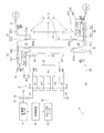
- FIG. 2 is a schematic diagram showing the overall configuration of the automatic transmission.
- FIG. 3 is a configuration diagram of a screw feed mechanism provided in the automatic transmission.
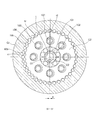
- FIG. 4 is a block diagram of a cycloid reducer provided in the power transmission mechanism of the automatic transmission.
- FIG. 5 is an explanatory view showing an operation at the time of shifting of the automatic transmission.
- FIG. 1 schematically shows an overall configuration of a power transmission system (hereinafter referred to as “drive system”) P of a vehicle equipped with an automatic transmission 1 according to an embodiment of the present invention.
- drive system a power transmission system
- the drive system P includes an internal combustion engine (hereinafter simply referred to as “engine”) ENG as a drive source, and the automatic transmission 1 on a power transmission path that connects the engine ENG and the left and right drive wheels WHl and WHr. It has.
- the engine ENG and the automatic transmission 1 are connected via a torque converter T / C having a lockup clutch.
- the automatic transmission 1 converts the rotational power input from the engine ENG at a predetermined gear ratio and outputs it to the drive wheels WHl and WHr via the differential gear DEF.
- the rotational power output from the automatic transmission 1 is transmitted to the drive shafts DSl and DSr via the final gear train or sub-transmission (both not shown) and the differential gear DEF set to a predetermined reduction ratio,
- the drive wheels WHl and WHr are rotated.
- the operations of the engine ENG and the automatic transmission 1 are controlled by the engine controller ECU and the transmission controller 9, respectively.
- Each of the engine controller ECU and the transmission controller 9 is configured as an electronic control unit, and includes a central processing unit (CPU), various storage devices such as a RAM and a ROM, and a microcomputer provided with an input / output interface.
- the engine controller ECU inputs a detection signal from an operation state sensor that detects the operation state of the engine 1 and executes a predetermined calculation based on the operation state, so that the fuel injection amount, fuel injection timing, and ignition timing of the engine ENG. Etc. are set.
- driving state sensors there are provided an accelerator sensor 111 that detects the amount of operation of the accelerator pedal by the driver, a rotational speed sensor 112 that detects the rotational speed of the engine ENG, a cooling water temperature sensor 113 that detects the temperature of engine cooling water, and the like.
- an air flow meter, a throttle sensor, a fuel pressure sensor, an air-fuel ratio sensor, and the like are provided.
- the transmission controller 9 is communicably connected to the engine controller ECU via a CAN standard bus or the like. Further, in relation to the control of the automatic transmission 1, a vehicle speed sensor 211 that detects the traveling speed of the vehicle, an input side rotational speed sensor 212 that detects the rotational speed of the input shaft of the automatic transmission 1, and the output of the automatic transmission 1. An output side rotational speed sensor 213 that detects the rotational speed of the shaft, a hydraulic oil temperature sensor 214 that detects the temperature of the hydraulic oil of the automatic transmission 1, a shift position sensor 215 that detects the position of the shift lever, and the like are provided.
- the transmission controller 9 inputs the accelerator opening and the like as the operating state of the engine ENG from the engine controller ECU, and also inputs detection signals of these sensors.
- the transmission controller 9 determines the shift range selected by the driver based on the signal from the shift position sensor 215, sets the target gear ratio of the automatic transmission 1 based on the accelerator opening, the vehicle speed, and the like.
- the electric motors 7 and 8 are controlled to apply a predetermined pulley thrust corresponding to the target gear ratio to the movable pulleys 32 and 42 of the primary pulley 3 and the secondary pulley 4.
- FIG. 2 schematically shows the overall configuration of the automatic transmission 1 according to the present embodiment.
- FIG. 2 shows only one side of the primary pulley 3 and the secondary pulley 4 with respect to the rotation axes X1 and X2 of the pulley.
- the automatic transmission 1 is a continuously variable automatic transmission and constitutes a transmission for a vehicle.
- the automatic transmission 1 includes a variator 2 including a primary pulley 3, a secondary pulley 4, and a belt 5 wound around the pulleys 3 and 4.
- the automatic transmission 1 can adjust the gear ratio steplessly by changing the winding radius of the belt 5 in the primary pulley 3 and the secondary pulley 4.
- the rotation speed ratio between 4 corresponds to this.
- the automatic transmission 1 outputs the torque input from the engine E via the torque converter T / C to the output shaft 22 connected to the differential gear DEF after shifting with a predetermined gear ratio.
- the primary pulley 3 constitutes a “first pulley”
- the secondary pulley 4 constitutes a “second pulley”.
- the belt 5 may be a steel belt in which a plurality of elements arranged in the plate thickness direction are bound by a hoop or a band, and is not limited to this, and may be a chain belt.
- the primary pulley 3 includes a fixed pulley 31 and a movable pulley 32 provided so as to be displaceable in the direction of the rotation axis X1 of the primary pulley 3 with respect to the fixed pulley 31.
- the movable pulley 32 is connected to the fixed pulley 31. On the other hand, it is attached in a state where relative rotation around the rotation axis X1 is restricted.
- the fixed pulley 31 and the movable pulley 32 have sheave surfaces 312a and 322a facing each other, and a V-groove 33 around which the belt 5 is wound around the primary pulley 3 is formed by these sheave surfaces 312a and 322a.
- the secondary pulley 4 includes a fixed pulley 41 and a movable pulley 42.
- the movable pulley 42 can be displaced in the direction of the rotation axis X ⁇ b> 2 of the secondary pulley 4 with respect to the fixed pulley 41.
- the sheave surfaces 412a and 422a of the fixed pulley 41 and the movable pulley 42 facing each other form a V groove 43 around which the belt 5 is wound around the secondary pulley 4.
- the rotation shafts X1 and X2 of the pulleys are formed by the rotation shafts of the fixed pulleys 31 and 41.
- the primary pulley 3 and the secondary pulley 4 are provided with screw feed mechanisms 35 and 45, respectively, and the output torque of an electric motor (corresponding to a first motor, hereinafter referred to as “shift motor”) 7 provided for shifting is screw fed.
- a pulley thrust is generated that is transmitted to the movable pulleys 32 and 42 via the mechanisms 35 and 45 and presses the movable pulleys 32 and 42 in the direction of narrowing the groove width of the V-grooves 33 and 43.
- clamp motor an electric motor (corresponding to a second motor, hereinafter referred to as “clamp motor”) 8 provided for belt clamping is transmitted to the movable pulleys 32 and 42 via the screw feed mechanisms 35 and 45, and the belt
- the control device 9 is configured as an electronic control unit, and includes a microcomputer, a storage device such as a ROM and a RAM, and an input / output interface. In the present embodiment, the control device 9 is realized by the transmission controller 9.
- FIG. 3 shows the configuration of the screw feed mechanisms 35 and 45 provided in the automatic transmission 1.
- FIG. 3A shows the screw feed mechanism 35 on the primary pulley 3 side
- FIG. 3B shows the screw feed mechanism 45 on the secondary pulley 4 side.
- the screw feed mechanism 35 on the primary pulley 3 side will be described as a representative example.
- the screw feed mechanism 35 includes a fixing member 36 that is externally fitted to the rotation shaft 311 of the fixed pulley 31, and a fixing member 36 (specifically, a fixing member). 36, a movable member 37 extrapolated to 36 cylindrical portions 361).
- the movable member 37 is supported by the radial bearing B2 with respect to the rotating shaft 321 of the movable pulley 32, and is in contact with the sheave portion 322 of the movable pulley 32 via the thrust bearing SB.
- the fixed member 36 is in a state where movement in the axial direction is restricted by a radial bearing B1 that rotatably supports the rotating shaft 311 of the fixed pulley 31 with respect to the pulley case C, and relative rotation with respect to the pulley case C is restricted. is there.
- Relative rotation of the fixing member 36 can be regulated by directly engaging the fixing member 36 and the pulley case C with irregularities or engaging them with each other via a rotation regulating member.
- the fixed member 36 constitutes a shaft portion of a ball screw feed mechanism, and holds a plurality of balls Ba between the movable member 37 (specifically, the pressing portion 371 of the movable member 37).
- the fixed member 36 moves along the rotation axis X1 of the primary pulley 3 with respect to the movable member 37 when the movable member 37 is driven to rotate. Giving linear displacement.
- the movable member 37 connects the cylindrical pressing portion 371 that contacts the sheave portion 322 of the movable pulley 32, the outer cylinder portion 372 having an outer diameter larger than the pressing portion 371, and the pressing portion 371 and the outer cylinder portion 372. And a plurality of gear teeth are formed on the outer periphery of the outer cylindrical portion 372.
- a linear displacement based on the rotation is given to the movable member 37 by the ball screw feed mechanism, and the movable member 37 is thrust bearing SB. And pressed against the sheave portion 322 of the movable pulley 32.
- the movable member 47 is fixed to the fixed pulley of the movable pulley 42 by the torque input through the outer peripheral portion 472. It is displaced in a direction allowing separation from 41 (in other words, a direction in which the groove width of the V-groove 43 is increased).
- the movable member 37 is fixed to the fixed pulley 31 of the movable pulley 32 by the torque input via the outer peripheral portion 372 in the screw feed mechanism 35 on the primary pulley 3 side.
- the torque input through the outer peripheral portion 472 is used for displacement in a direction that allows separation from the direction (in other words, a direction in which the groove width of the V groove 33 is increased).
- the movable member 47 is displaced in the direction in which the movable pulley 42 is pressed (in other words, the direction in which the groove width of the V groove 43 is narrowed).
- the cycloid reduction gear 6 is interposed between the transmission motor 7 and the clamp motor 8 and the screw feed mechanisms 35 and 45.
- the cycloid reduction gear 6 basically has the same function as a pinion gear type planetary gear mechanism that is generally provided in an automatic transmission, and outputs the output torque of at least one of the transmission motor 7 and the clamp motor 8 to a screw feed mechanism 35. , 45 are transmitted to the movable pulleys 32, 42.
- the cycloid reducer 6 may have the same configuration as that generally known as a cycloid reducer, and can be broadly divided into an input shaft I (corresponding to a sun gear in a planetary gear mechanism), and an internal gear. G1 (also corresponding to a ring gear), an external gear G2 (also corresponding to a pinion gear), and an output shaft 63 connected to the external gear G2 via an internal pin (not shown).
- a motor pinion 72 fixed to the output shaft 71 of the transmission motor 7 is engaged with an external tooth portion 61 formed on the outer periphery of the internal gear G1, and the output torque of the transmission motor 7 is changed to the motor pinion 72 and the external tooth portion. 61 is transmitted to the internal gear G1.
- the input shaft I is directly connected to the output shaft 81 of the clamp motor 8, and the output torque of the clamp motor 8 is transmitted to the input shaft I via the output shaft 81.
- FIG. 4 shows the configuration of the cycloid reducer 6 by a cross section taken along line IV-IV in FIG.
- the cycloid reducer 6 will be further described with reference to FIG. 4 while also referring to FIG.
- the cycloid reducer 6 decelerates the torque input through the input shaft I at a predetermined reduction ratio and outputs it from the output shaft 63.
- the external gear G2 rotates while performing an eccentric oscillating motion relative to the internal gear G1, and the rotational component of the external gear G2 is extracted as the output of the speed reducer 6. It is also possible to output via the internal gear G1 by fixing the external gear G2.
- the cycloid reducer 6 is attached to the input shaft I, the eccentric body 101 that is fitted to the input shaft I and rotates integrally with the input shaft I, and is attached to the eccentric body 101 via the radial bearing 102.
- An output shaft 63 having a member 103 to be taken out and connected to the external gear G ⁇ b> 2 through the member 103 is provided.
- the input shaft I and the internal gear G1 are in a state of being relatively rotatable around a common axis Xb.
- the eccentric body 101 is attached to the input shaft I in a state of being eccentric by a predetermined eccentricity amount e with respect to the center O1 of the input shaft I (the center of the eccentric body 101 is indicated by O2).
- a plurality of inner roller holes 104 are formed in the external gear G2 at intervals in the circumferential direction (in the present embodiment, with an equal interval between each other).
- the inner pin 103 which is a “member for taking out the rotational component of” is loosely fitted.
- a flange portion F is formed on the output shaft 63, and the inner pin 103 is loosely fitted in the inner roller hole 104 of the external gear G 2, and is fixed or joined to the flange portion F, so that the external gear G 2 and the output are output.
- the shaft 63 is connected to the inner pin 103 via the inner pin 103.
- the external gear G2 has external teeth t2 having a trochoidal tooth profile (specifically, an epitrochoidal parallel curve tooth profile) formed on the outer periphery thereof.
- the external gear G2 is inscribed and engaged with the internal gear G1 via the external tooth t2.
- a plurality of outer pins 105 are attached to the inner gear G1 on the inner periphery. Specifically, a plurality of pin grooves 106 are formed on the entire inner periphery of the internal gear G ⁇ b> 1, and the outer pins 105 are fitted into the pin grooves 106. A tooth surface of the inner tooth t1 is formed by a portion of the outer pin 105 exposed to the inner diameter side.
- the eccentric body 101 rotates integrally with the input shaft I, and the force is transmitted to the external gear G2.
- the eccentric body 101 rotates once for each rotation of the input shaft I.
- the external gear G2 also tries to rotate around the input shaft I.
- the rotational speed of the external gear G2 corresponds to the difference in the number of teeth between the external gear G2 and the internal gear G1
- the rotational direction of the external gear G2 is the rotational direction of the input shaft I. The reverse direction.
- the reduction ratio of the cycloid reduction gear 6 is set to 60 by setting the number of teeth n of the external gear G2 to 60. This is a much larger reduction ratio than that set for a typical planetary gear mechanism.
- the peristaltic component is absorbed by the gap between the inner pin 103 and the inner roller hole 104, and only the rotational component is transmitted to the output shaft 63 via the inner pin 103. Is achieved.
- the reduction ratio n is not limited to 60, and can be set as appropriate.
- the output gear 63 on the secondary pulley 4 side is coupled to the output shaft 63 of the cycloid reducer 6 at the tip thereof.
- the output gear portion 64 engages with a gear portion (outer cylinder portion 472) provided on the movable member 47 of the screw feed mechanism 45 on the secondary pulley 4 side, and when the external gear G2 rotates, the output of the cycloid reducer 6 is output. Torque is input to the screw feed mechanism 45 via the output shaft 63 and the output gear portion 64.
- the internal gear G1 is provided with an annular output gear portion 62 in a cylindrical portion extending in parallel with the output shaft 63.
- the output gear portion 62 on the primary pulley 3 side is screw-feeded on the primary pulley 3 side.
- the cycloid reducer 6 adjusts the torque for changing the speed ratio of the variator 2 or fixing the speed ratio from the output torque of the speed change motor 7 and the output torque of the clamp motor 8.
- the output torque of the speed change motor 7 is input to the screw feed mechanisms 35, 45 via the cycloid reducer 6, and the movable members 37, 47 are connected to the rotary shaft X 1, It is converted into a force (pulley thrust) that is driven along X2.
- a force Pulley thrust
- the movable pulley 32 is pressed by the movable member 37 of the screw feed mechanism 35, the groove width of the V groove 33 is reduced on the primary pulley 3 side, while the movable pulley 42 is moved by the movable member 47 of the screw feed mechanism 45. Since the displacement in the direction away from the fixed pulley 41 is allowed, the groove width of the V-groove 43 is expanded on the secondary pulley 4 side.
- FIG. 5 shows an operation at the time of shifting of the automatic transmission 1 according to the present embodiment.
- the clamp motor 8 is driven to generate a holding torque, the input shaft I is fixed, and a pulley thrust for changing the speed ratio is generated by the speed changing motor 7.
- a pulley thrust for changing the speed ratio is generated by the speed changing motor 7.
- the output torque of the speed change motor 7 is input to the internal gear G1 via the motor pinion 72 and the external gear 61 of the internal gear G1, and the internal gear G1 rotates around the central axis X of the cycloid reduction gear 6.
- the external gear G2 rotates around the eccentric body 101 following this.
- the output gear portion 62 coupled to the internal gear G1 and the output gear portion 64 coupled to the external gear G2 via the output shaft 63 rotate around the central axis X in the same direction CW.
- the output torque of the transmission motor 7 is input to the movable members 37 and 47 of the screw feed mechanisms 35 and 45.
- Rotation of the output gears 62 and 64 is converted into linear displacement of the movable members 37 and 47 by the screw feed mechanisms 35 and 45, and the movable members 37 and 47 move along the rotation axes X1 and X2.
- the screw feed mechanism 35 on the primary pulley 3 side when the movable member 37 moves in the direction approaching the movable pulley 32 and presses the sheave portion 322 of the movable pulley 32 so as to narrow the groove width of the V groove 33,
- the screw feed mechanism 45 on the secondary pulley 4 side the movable member 47 is separated from the sheave portion 422 of the movable pulley 42, and the displacement of the movable pulley 42 in the direction away from the fixed pulley 41 is allowed.
- the groove width of the V groove 33 in the primary pulley 3 is reduced and the winding radius of the belt 5 is increased, while the groove width of the V groove 43 in the secondary pulley 4 is increased and the winding radius of the belt 5 is increased.
- the speed is reduced and the shift is executed.
- the input of the cycloid reducer 6 is input during belt clamping.
- the counter torque acting on the shaft I is 0.075 Nm.
- the belt-clamping electric motor (clamp motor 8) is installed in addition to the transmission electric motor (transmission motor 7). Unlike the automatic transmission described above, it is possible to appropriately form the belt clamping force and reduce the belt friction.
- the counter torque acting on the input shaft I of the cycloid reduction gear 6 based on the reaction force at the time of belt clamping from the variator 2 is reduced more than the friction torque in the clamp motor 8, and torque is generated by the clamp motor 8.
- the necessary belt clamping force can be ensured in a state where the supply of power to the clamp motor 8 is stopped.
Landscapes
- Engineering & Computer Science (AREA)
- General Engineering & Computer Science (AREA)
- Mechanical Engineering (AREA)
- Transmissions By Endless Flexible Members (AREA)
- Retarders (AREA)
- Control Of Transmission Device (AREA)
Abstract
第1プーリと、第2プーリと、第1プーリおよび第2プーリに掛け回されたベルトと、を有するバリエータと、第1または第2プーリに対し、バリエータを変速させるためのプーリ推力を与える第1モータと、バリエータにベルトクランプ力を生じさせる第2モータと、第2モータとバリエータとの間に設けられ、第2モータの出力トルクをバリエータに伝達させる動力伝達機構と、を備える自動変速機が提供される。動力伝達機構は、第2モータからの入力トルクを減速してバリエータに伝達させるサイクロイド減速機を備える。
Description
本発明は、変速用の電動モータとベルトクランプ用の電動モータとを備える自動変速機およびその制御方法に関する。
JP62-013853にあるように、無段型の自動変速機において、一対のプーリがベルトを両側から挟み込む力(以下「ベルトクランプ力」という)を、固定レース、稼働レースおよび皿バネを有する調圧カム機構により生じさせることが知られている。カムは、その特性上、トルクがかからないとプーリに対する推力を生じさせることができないことから、皿バネを設置することでトルクがかかっていない場合にもある程度のプーリ推力を生じさせることを可能とし、充分なトルクが得られない初期段階におけるベルト滑りを抑制するものである。
しかし、JP62-013853では、皿バネの設置により、プーリ比毎の必要推力に対して低減速比側(換言すれば、高変速段側)でベルトクランプ力が過大となり、ベルトフリクションが悪化する、という問題がある。
これに対し、本出願人による日本国特許出願第2016-022312号(以下「先願1」という)には、変速用とベルトクランプ用とのそれぞれに電動モータが設けられ、変速用の電動モータにより変速動作に必要なプーリ推力を与える一方、クランプ用の電動モータによりベルトクランプ力を生じさせるようにした自動変速機が開示されている。このものによれば、皿バネに起因した推力過剰の問題の解消を図ることが可能である。しかし、先願1では、クランプ中にクランプモータに対してどのように電力を供給するかが明らかにされておらず、仮にクランプ中、常に電力を供給し続けることとすれば、消費電力の増大を避けることができない。
そこで、本発明では、変速用とベルトクランプ用とのそれぞれに電動モータを備える自動変速機において、消費電力の増大を抑制しつつ、ベルトクランプ力を適切に形成可能とすることを目的とする。
本発明の一形態では、第1プーリと、第2プーリと、第1プーリおよび第2プーリに掛け回されたベルトと、を有するバリエータと、第1または第2プーリに対し、バリエータを変速させるためのプーリ推力を与える第1モータと、バリエータにベルトクランプ力を生じさせる第2モータと、第2モータとバリエータとの間に設けられ、第2モータの出力トルクをバリエータに伝達させる動力伝達機構と、を備える自動変速機を提供する。本形態では、動力伝達機構が、第2モータからの入力トルクを減速してバリエータに伝達させるサイクロイド減速機を備える。
本発明の一形態によれば、ベルトクランプ力を生じさせる第2モータを設置したことで、ベルトクランプ力を適切に形成することが可能となる。そして、ベルトクランプ時の反力としてバリエータから伝達されるカウンタトルクをサイクロイド減速機により大幅に減少させることができるので、ベルトクランプ力の確保に要する第2モータの消費電力を削減することが可能となる。
以下、図面を参照して、本発明の実施形態について説明する。
(車両駆動系の構成)
図1は、本発明の一実施形態に係る自動変速機1を搭載した車両の動力伝達系(以下「駆動系」という)Pの全体構成を概略的に示している。
図1は、本発明の一実施形態に係る自動変速機1を搭載した車両の動力伝達系(以下「駆動系」という)Pの全体構成を概略的に示している。
本実施形態に係る駆動系Pは、駆動源として内燃エンジン(以下、単に「エンジン」という)ENGを備え、エンジンENGと左右の駆動輪WHl、WHrとをつなぐ動力伝達経路上に自動変速機1を備えている。エンジンENGと自動変速機1とは、ロックアップクラッチを備えたトルクコンバータT/Cを介して接続されている。自動変速機1は、エンジンENGから入力される回転動力を所定の変速比で変換し、ディファレンシャルギアDEFを介して駆動輪WHl、WHrに出力する。
自動変速機1から出力された回転動力は、所定の減速比に設定された最終ギア列または副変速機(いずれも図示せず)およびディファレンシャルギアDEFを介して駆動軸DSl、DSrに伝達され、駆動輪WHl、WHrを回転させる。
(制御システムの構成および基本動作)
エンジンENGおよび自動変速機1の動作は、エンジンコントローラECU、変速機コントローラ9により夫々制御される。エンジンコントローラECUおよび変速機コントローラ9は、いずれも電子制御ユニットとして構成され、中央演算装置(CPU)、RAMおよびROM等の各種記憶装置、入出力インターフェース等を備えたマイクロコンピュータからなる。
エンジンENGおよび自動変速機1の動作は、エンジンコントローラECU、変速機コントローラ9により夫々制御される。エンジンコントローラECUおよび変速機コントローラ9は、いずれも電子制御ユニットとして構成され、中央演算装置(CPU)、RAMおよびROM等の各種記憶装置、入出力インターフェース等を備えたマイクロコンピュータからなる。
エンジンコントローラECUは、エンジン1の運転状態を検出する運転状態センサの検出信号を入力し、運転状態をもとに所定の演算を実行して、エンジンENGの燃料噴射量、燃料噴射時期および点火時期等を設定する。運転状態センサとして、運転者によるアクセルペダルの操作量を検出するアクセルセンサ111、エンジンENGの回転速度を検出する回転速度センサ112、エンジン冷却水の温度を検出する冷却水温度センサ113等が設けられるほか、図示しないエアフローメータ、スロットルセンサ、燃料圧力センサおよび空燃比センサ等が設けられている。
変速機コントローラ9は、エンジンコントローラECUに対し、CAN規格のバス等を介して互いに通信可能に接続されている。さらに、自動変速機1の制御に関連して、車両の走行速度を検出する車速センサ211、自動変速機1の入力軸の回転速度を検出する入力側回転速度センサ212、自動変速機1の出力軸の回転速度を検出する出力側回転速度センサ213、自動変速機1の作動油の温度を検出する作動油温度センサ214、シフトレバーの位置を検出するシフト位置センサ215等が設けられており、変速機コントローラ9は、エンジンコントローラECUからエンジンENGの運転状態としてアクセル開度等を入力するほか、これらのセンサの検出信号を入力する。
そして、変速機コントローラ9は、シフト位置センサ215からの信号に基づき運転者により選択されたシフトレンジを判定するとともに、アクセル開度および車速等に基づき自動変速機1の目標変速比を設定し、電動モータ7、8を制御して、プライマリプーリ3およびセカンダリプーリ4の可動プーリ32、42に対して目標変速比に応じた所定のプーリ推力を作用させる。
(自動変速機の全体構成)
図2は、本実施形態に係る自動変速機1の全体構成を概略的に示している。
図2は、本実施形態に係る自動変速機1の全体構成を概略的に示している。
図2は、プライマリプーリ3およびセカンダリプーリ4のうち、プーリの回転軸X1、X2を基準とした片側のみを示している。
本実施形態において、自動変速機1は、無段型の自動変速機であり、車両用の変速装置を構成する。
自動変速機1は、プライマリプーリ3と、セカンダリプーリ4と、これらのプーリ3、4に掛け回されたベルト5と、から構成されるバリエータ2を備える。自動変速機1は、プライマリプーリ3およびセカンダリプーリ4におけるベルト5の巻掛半径を変更することで、変速比を無段階に調整することが可能である。ここで、変速比とは、バリエータ入力軸21の回転速度Niと、バリエータ出力軸22の回転速度Noと、の比(=No/Ni)をいい、本実施形態では、プライマリプーリ3とセカンダリプーリ4との間の回転速度比がこれに相当する。自動変速機1は、エンジンEからトルクコンバータT/Cを介して入力したトルクを、所定の変速比による変速後、ディファレンシャルギアDEFに接続された出力軸22に出力する。プライマリプーリ3は、「第1プーリ」を構成し、セカンダリプーリ4は、「第2プーリ」を構成する。ベルト5は、板厚方向に並べた複数のエレメントをフープないしバンドにより結束したスチールベルトであってもよく、これに限らず、チェーンベルトであってもよい。
プライマリプーリ3は、固定プーリ31と、固定プーリ31に対してプライマリプーリ3の回転軸X1の方向に変位可能に設けられた可動プーリ32と、から構成され、可動プーリ32は、固定プーリ31に対し、回転軸X1まわりの相対回転が規制された状態で取り付けられている。固定プーリ31および可動プーリ32は、互いに対向するシーブ面312a、322aを有し、これらのシーブ面312a、322aにより、ベルト5がプライマリプーリ3に巻き掛けられるV溝33が形成される。
セカンダリプーリ4も、プライマリプーリ3と同様に、固定プーリ41と可動プーリ42とから構成され、可動プーリ42は、固定プーリ41に対し、セカンダリプーリ4の回転軸X2の方向に変位可能であるとともに、回転軸X2まわりの相対回転が規制された状態で取り付けられている。固定プーリ41および可動プーリ42の互いに対向するシーブ面412a、422aにより、ベルト5がセカンダリプーリ4に巻き掛けられるV溝43が形成される。
本実施形態では、プライマリプーリ3およびセカンダリプーリ4のそれぞれにおいて、固定プーリ31、41の回転軸によりプーリの回転軸X1、X2が形成される。
プライマリプーリ3およびセカンダリプーリ4のそれぞれにねじ送り機構35、45が設けられ、変速用に設けられた電動モータ(第1モータに相当し、以下「変速モータ」という)7の出力トルクがねじ送り機構35、45を介して可動プーリ32、42に伝達され、V溝33、43の溝幅を狭める方向に可動プーリ32、42を押圧するプーリ推力が生じるように構成されている。さらに、ベルトクランプ用に設けられた電動モータ(第2モータに相当し、以下「クランプモータ」という)8の出力トルクがねじ送り機構35、45を介して可動プーリ32、42に伝達され、ベルト5を可動プーリ32、42および固定プーリ31、41により挟持するベルトクランプ力が生じるように構成されている。
本実施形態において、変速モータ7には、最大回転数が大きい電動モータが採用され、クランプモータ8には、最大出力トルクが大きい電動モータが採用されている。変速モータ7およびクランプモータ8の動作は、制御装置9により制御される。制御装置9は、電子制御ユニットとして構成され、マイクロコンピュータ、ROMおよびRAM等の記憶装置、入出力インターフェースを内蔵する。本実施形態において、制御装置9は、変速機コントローラ9により具現される。
(ねじ送り機構の構成)
図3は、自動変速機1に備わるねじ送り機構35、45の構成を示している。図3(a)は、プライマリプーリ3側のねじ送り機構35を示し、同図(b)は、セカンダリプーリ4側のねじ送り機構45を示している。
図3は、自動変速機1に備わるねじ送り機構35、45の構成を示している。図3(a)は、プライマリプーリ3側のねじ送り機構35を示し、同図(b)は、セカンダリプーリ4側のねじ送り機構45を示している。
プライマリプーリ3側のねじ送り機構35に代表させて説明すると、ねじ送り機構35は、固定プーリ31の回転軸311に外嵌された固定部材36と、固定部材36(具体的には、固定部材36の筒状部361)に外挿された可動部材37と、を有する。
可動部材37は、可動プーリ32の回転軸321に対してラジアル軸受B2により支持される一方、可動プーリ32のシーブ部322に対してスラスト軸受SBを介して当接した状態にある。
固定部材36は、固定プーリ31の回転軸311をプーリケースCに対して回転可能に支持するラジアル軸受B1により軸方向の移動が規制されるとともに、プーリケースCに対する相対回転が規制された状態にある。固定部材36の相対回転は、固定部材36とプーリケースCとを凹凸等により直接噛み合わせたり、回転規制部材を介して互いに係合させたりすることで規制可能である。本実施形態において、固定部材36は、ボールねじ送り機構のシャフト部を構成し、可動部材37(具体的には、可動部材37の押圧部371)との間に複数のボールBaを保持する。プーリケースCに対する固定部材36の回転が規制された状態にあることから、固定部材36は、可動部材37が回転駆動された場合に、可動部材37に対してプライマリプーリ3の回転軸X1に沿った線形変位を付与する。
可動部材37は、可動プーリ32のシーブ部322に当接する円筒状の押圧部371と、押圧部371よりも大きな外径を有する外筒部372と、押圧部371と外筒部372とをつなぐ円板状の接続部373と、を有し、外筒部372の外周上に、複数のギア歯が形成されている。外筒部372のギア歯を介して電動モータ7、8の出力トルクが入力されることで、可動部材37にボールねじ送り機構により回転に基づく線形変位が付与され、可動部材37がスラスト軸受SBを介して可動プーリ32のシーブ部322に押し付けられる。
ここで、バリエータ2の変速比を変更する際に、プライマリプーリ3側のねじ送り機構35において、外周部372を介して入力されたトルクにより可動部材37が可動プーリ32を押圧する方向(換言すれば、V溝33の溝幅を狭める方向)に変位する場合は、セカンダリプーリ4側のねじ送り機構45では、外周部472を介して入力されたトルクにより可動部材47が可動プーリ42の固定プーリ41からの離間を許容する方向(換言すれば、V溝43の溝幅を広げる方向)に変位する。
これとは反対に、バリエータ2の変速比を変更する際に、プライマリプーリ3側のねじ送り機構35において、外周部372を介して入力されたトルクにより可動部材37が可動プーリ32の固定プーリ31からの離間を許容する方向(換言すれば、V溝33の溝幅を広げる方向)に変位する場合は、セカンダリプーリ4側のねじ送り機構45では、外周部472を介して入力されたトルクにより可動部材47が可動プーリ42を押圧する方向(換言すれば、V溝43の溝幅を狭める方向)に変位する。
図2に戻り、本実施形態では、変速モータ7およびクランプモータ8とねじ送り機構35、45との間に、サイクロイド減速機6が介装されている。
サイクロイド減速機6は、基本的には、自動変速機一般に備わるピニオンギア型の遊星歯車機構と同様な機能を有し、変速モータ7およびクランプモータ8のうち少なくとも一方の出力トルクをねじ送り機構35、45を介して可動プーリ32、42に伝達させるものである。サイクロイド減速機6は、サイクロイド減速機として一般的に知られているものと同様の構成であってよく、大別すれば、入力軸I(遊星歯車機構におけるサンギアに対応する)と、内歯歯車G1(同じくリングギアに対応する)と、外歯歯車G2(同じくピニオンギアに対応する)と、図示しない内ピンを介して外歯歯車G2と連結された出力軸63と、から構成される。内歯歯車G1の外周上に形成された外歯部61に変速モータ7の出力軸71に固定されたモータピニオン72が係合し、変速モータ7の出力トルクが、モータピニオン72および外歯部61を介して内歯歯車G1に伝達される。一方で、入力軸Iがクランプモータ8の出力軸81に直結され、クランプモータ8の出力トルクが、出力軸81を介して入力軸Iに伝達される。
図4は、サイクロイド減速機6の構成を、図2のIV-IV線に沿った断面により示している。
図2を併せて参照しつつ、図4によりサイクロイド減速機6についてさらに説明する。
サイクロイド減速機6は、入力軸Iを通じて入力したトルクを所定の減速比で減速させ、出力軸63から出力する。外歯歯車G2が内歯歯車G1に対して相対的に偏心揺動運動を行いながら回転し、外歯歯車G2の回転成分を当該減速機6の出力として取り出すものである。外歯歯車G2を固定することで、内歯歯車G1を介して出力することも可能である。
サイクロイド減速機6は、入力軸Iと、入力軸Iに嵌合し、入力軸Iと一体に回転する偏心体101と、偏心体101にラジアル軸受102を介して取り付けられ、外周上に複数の外歯が形成された円環状の外歯歯車G2と、外歯歯車G2の外歯と噛み合う複数の内歯が内周上に形成された内歯歯車G1と、外歯歯車G2の回転成分を取り出す部材103を有し、この部材103を介して外歯歯車G2と接続された出力軸63と、を備える。入力軸Iと内歯歯車G1とは、互いに共通の軸Xbを中心として相対回転可能な状態にある。
偏心体101は、入力軸Iの中心O1に対して所定の偏心量eだけ偏心させた状態で入力軸Iに取り付けられている(偏心体101の中心を、O2により示す)。
外歯歯車G2には、周方向に間隔を空けて(本実施形態では、互いに等しい間隔を空けて)複数の内ローラ孔104が形成され、内ローラ孔104のそれぞれに、上記「外歯歯車の回転成分を取り出す部材」である内ピン103が遊嵌されている。出力軸63にフランジ部Fが形成され、内ピン103が外歯歯車G2の内ローラ孔104に遊嵌されるとともに、このフランジ部Fに固着または接合されることで、外歯歯車G2と出力軸63とが内ピン103を介して接続された状態にある。
さらに、外歯歯車G2には、その外周上にトロコイド歯形(具体的には、エピトロコイド平行曲線歯形)の外歯t2が形成されている。外歯歯車G2は、この外歯t2を介して内歯歯車G1と内接係合する。
内歯歯車G1には、内周上に複数の外ピン105が取り付けられている。具体的には、内歯歯車G1の内周上にその全周に亘って複数のピン溝106が形成され、ピン溝106のそれぞれに外ピン105が嵌入されている。外ピン105のうち、内径側に露出する部分により内歯t1の歯面が形成される。
入力軸Iが回転すると、偏心体101が入力軸Iと一体に回転し、外歯歯車G2に力が伝達される。ここで、偏心体101の回転は、入力軸Iの一回転毎に一回である。偏心体101の回転に伴い、外歯歯車G2も入力軸Iまわりで回転しようとするが、内歯歯車G1との噛合に起因した拘束により回転が制約された状態にあるため、外歯歯車G2は、入力軸Iを基準とした偏心搖動運動と、入力軸Iを中心とする多少の自転運動とを同時に行うことになる。ここで、外歯歯車G2の回転速度は、外歯歯車G2と内歯歯車G1との歯数の差に応じたものとなり、外歯歯車G2の回転方向は、入力軸Iの回転方向とは逆向きである。
例えば、外歯歯車G2の歯数をnとし、内歯歯車G1の歯数をn+1とすると、これらの歯数差Dnは、1である。よって、内歯歯車G1は、入力軸Iが一回転する間に外歯歯車G2に対して一歯数分だけ回転方向にずれることになる。これが外歯歯車G2の回転成分として内ピン103を介して出力軸63に伝達される。そして、このことは、入力軸Iの回転が1/nだけ減速された状態で外歯歯車G2に伝達され、入力軸Iと出力軸63との間の減速比がnであることを意味する。本実施形態では、外歯歯車G2の歯数nを60とすることで、サイクロイド減速機6の減速比が60に設定されている。これは、一般的な遊星歯車機構について設定されるものよりも、大幅に大きな減速比である。
外歯歯車G2の回転は、内ピン103と内ローラ孔104との間の隙間により搖動成分が吸収され、内ピン103を介して回転成分のみが出力軸63に伝達され、減速比nの変速が達成される。減速比nは、60に限らず、適宜に設定することが可能である。
本実施形態において、サイクロイド減速機6の出力軸63には、その先端に、セカンダリプーリ4側の出力ギア部64が結合されている。出力ギア部64は、セカンダリプーリ4側のねじ送り機構45の可動部材47に設けられたギア部(外筒部472)と係合し、外歯歯車G2が回転すると、サイクロイド減速機6の出力トルクが出力軸63および出力ギア部64を介してねじ送り機構45に入力される。
さらに、内歯歯車G1には、出力軸63と平行に延びる筒状部に円環状の出力ギア部62が設けられ、このプライマリプーリ3側の出力ギア部62は、プライマリプーリ3側のねじ送り機構35の可動部材37に設けられたギア部(外筒部372)と係合し、内歯歯車G1が回転すると、サイクロイド減速機6の出力トルクが出力ギア部62を介してねじ送り機構35に入力される。
サイクロイド減速機6は、変速モータ7の出力トルクとクランプモータ8の出力トルクとから、バリエータ2の変速比を変更したり、変速比を固定したりするためのトルクを調整する。
具体的には、バリエータ2の変速比を変更する場合は、変速モータ7の出力トルクがサイクロイド減速機6を介してねじ送り機構35、45に入力され、可動部材37、47を回転軸X1、X2に沿って駆動する力(プーリ推力)に変換される。例えば、ねじ送り機構35の可動部材37により可動プーリ32が押圧されることで、プライマリプーリ3側でV溝33の溝幅が縮小される一方、ねじ送り機構45の可動部材47により可動プーリ42の固定プーリ41から離間する方向への変位が許容されることで、セカンダリプーリ4側でV溝43の溝幅が拡大される。
図5は、本実施形態に係る自動変速機1の変速時における動作を示している。
変速時では、クランプモータ8を駆動して保持トルクを発生させ、入力軸Iを固定するとともに、変速モータ7により変速比を変更するためのプーリ推力を生じさせる。変速モータ7の出力トルクを変化させ、プライマリプーリ3とセカンダリプーリ4とに作用するプーリ推力に差(以下「推力差」という)を生じさせることで、所望の変速比を達成する。
変速モータ7の出力トルクがモータピニオン72および内歯歯車G1の外歯部61を介して内歯歯車G1に入力され、内歯歯車G1がサイクロイド減速機6の中心軸Xまわりで回転する。内歯歯車G1が回転すると、これに追従して、外歯歯車G2が偏心体101を中心として回転する。これにより、内歯歯車G1に結合された出力ギア部62と、外歯歯車G2に出力軸63を介して連結された出力ギア部64と、が中心軸Xまわりで互いに同じ方向CWに回転し、変速モータ7の出力トルクがねじ送り機構35、45の可動部材37、47に入力される。
出力ギア部62、64の回転がねじ送り機構35、45により可動部材37、47の線形変位に変換され、可動部材37、47が回転軸X1、X2に沿って移動する。例えば、プライマリプーリ3側のねじ送り機構35において、可動部材37が可動プーリ32に近付く方向に移動し、V溝33の溝幅を狭めるように可動プーリ32のシーブ部322を押圧する場合は、セカンダリプーリ4側のねじ送り機構45において、可動部材47が可動プーリ42のシーブ部422から離間し、可動プーリ42の固定プーリ41から離れる方向の変位を許容する。これにより、プライマリプーリ3におけるV溝33の溝幅が狭められ、ベルト5の巻掛半径が拡大される一方、セカンダリプーリ4におけるV溝43の溝幅が広げられ、ベルト5の巻掛半径が縮小され、変速が実行される。
これに対し、変速比を保持する場合(換言すれば、プーリ推力が一定である場合)は、クランプモータ8への電力の供給を停止し、サイクロイド減速機6によりクランプモータ8におけるフリクショントルクを増大させ、ベルトクランプ力を維持する。換言すれば、サイクロイド減速機6により、バリエータ2からベルトクランプ時の反力に基づき入力軸Iに作用するカウンタトルクを、クランプモータ8におけるフリクショントルクよりも減少させるのである。
一例として、サイクロイド減速機6の減速比をR=60とした場合に、可動プーリ32または42に対する推力(プーリ推力)をN=50kN、ボールねじ送り機構の変換効率をη=0.88、ボールねじのリードをL=10mm、出力ギア部62または64における伝達効率をε=0.99、サイクロイド減速機6の伝達効率をν=0.1とすれば、ベルトクランプ時にサイクロイド減速機6の入力軸Iに作用するカウンタトルクは、0.075Nmとなる。これに対し、クランプモータ8におけるオイルシールの粘性摩擦トルクをT1=0.065Nm、ブラシの摩擦トルクをT2=0.04Nmとすると、これらのフリクショントルクに基づき入力軸Iに作用する入力トルクは、0.105Nmとなり、入力軸Iに対してカウンタトルクよりも大きなトルクがかかっていることになり、クランプモータ8によりトルクを出力せずに、可動プーリ32、42の位置を維持し、ベルトクランプ力を保持することが可能である。
(作用効果の説明)
以上で述べたように、本実施形態によれば、変速用の電動モータ(変速モータ7)に加え、ベルトクランプ用の電動モータ(クランプモータ8)を設置したことで、皿バネ等を用いるこれまでの自動変速機とは異なり、ベルトクランプ力を適切に形成し、ベルトフリクションを低減することが可能となる。
以上で述べたように、本実施形態によれば、変速用の電動モータ(変速モータ7)に加え、ベルトクランプ用の電動モータ(クランプモータ8)を設置したことで、皿バネ等を用いるこれまでの自動変速機とは異なり、ベルトクランプ力を適切に形成し、ベルトフリクションを低減することが可能となる。
そして、ベルトクランプ時の反力としてバリエータ2から伝達されるカウンタトルクをサイクロイド減速機6により大幅に減少させることができるので、ベルトクランプ力の確保に要する消費電力を削減することが可能となる。
具体的には、サイクロイド減速機6の入力軸Iに対してバリエータ2からベルトクランプ時の反力に基づき作用するカウンタトルクをクランプモータ8におけるフリクショントルクよりも減少させ、クランプモータ8によりトルクを生じさせることなく、換言すれば、クランプモータ8への電力の供給を停止した状態で、必要なベルトクランプ力を確保することができる。
さらに、クランプモータ8が故障した場合であってもベルトクランク力が確保されることで、車両の退避走行を可能とすることができる。
以上、本発明の実施形態について説明したが、上記実施形態は、本発明の適用例の一部を示すものに過ぎず、本発明の技術的範囲を上記実施形態の具体的構成に限定する趣旨ではない。本発明は、請求の範囲に記載した事項の範囲内において、様々な変更および修正が可能である。
本願は、2016年10月11日付けで日本国特許庁に出願された特願2016-200339号に基づく優先権を主張するものであり、その出願の全ての内容は、参照により本願の明細書に組み込まれる。
Claims (4)
- 第1プーリと、第2プーリと、前記第1プーリおよび前記第2プーリに掛け回されたベルトと、を有するバリエータと、
前記第1または第2プーリに対し、前記バリエータを変速させるためのプーリ推力を与える第1モータと、
前記バリエータにベルトクランプ力を生じさせる第2モータと、
前記第2モータと前記バリエータとの間に設けられ、前記第2モータの出力トルクを前記バリエータに伝達させる動力伝達機構と、
を備え、
前記動力伝達機構は、前記第2モータからの入力トルクを減速して前記バリエータに伝達させるサイクロイド減速機を備える、自動変速機。 - 第1プーリと、第2プーリと、前記第1プーリおよび前記第2プーリに掛け回されたベルトと、を有するバリエータと、
前記第1または第2プーリに対し、前記バリエータを変速させるためのプーリ推力を与える第1モータと、
前記バリエータにベルトクランプ力を生じさせる第2モータと、
前記第2モータと前記バリエータとの間に設けられ、前記第2モータの出力トルクを前記バリエータに伝達させる動力伝達機構と、
を備え、
前記動力伝達機構は、前記第2モータからの入力トルクを減速して前記バリエータに伝達させる高減速比ギアを備え、
前記高減速比ギアの減速比は、前記バリエータからベルトクランプ時の反力に基づき前記高減速比ギアの入力軸に作用するカウンタトルクが、前記第2モータにおけるフリクショントルクよりも小さくなる減速比である、自動変速機。 - 請求項1または2に記載の自動変速機であって、
前記自動変速機は、車両の駆動源と駆動輪とをつなぐ動力伝達経路上に設けられ、
前記第1プーリは、前記駆動源の出力軸と接続されたプライマリプーリであり、
前記第2プーリは、前記駆動輪の回転軸に接続されたセカンダリプーリである、自動変速機。 - 変速用の第1モータとベルトクランプ用の第2モータとを有する自動変速機において、変速比を保持している間のベルトクランプ力を確保する、自動変速機の制御方法であって、
前記第2モータと前記自動変速機のバリエータとの間に、前記第2モータからの入力トルクを減速して前記バリエータに伝達させる高減速比ギアを介装し、
前記バリエータの変速比を保持するベルトクランプ時において、
前記第2モータに対する電力の供給を停止し、
前記高減速比ギアにより、前記バリエータから前記高減速比ギアの入力軸に作用するカウンタトルクを、前記第2モータにおけるフリクショントルクよりも減少させる、自動変速機の制御方法。
Priority Applications (3)
| Application Number | Priority Date | Filing Date | Title |
|---|---|---|---|
| US16/326,867 US11293531B2 (en) | 2016-10-11 | 2017-10-02 | Automatic transmission and control method of automatic transmission |
| CN201780051667.6A CN109661529B (zh) | 2016-10-11 | 2017-10-02 | 自动变速器及自动变速器的控制方法 |
| JP2018544965A JP6622925B2 (ja) | 2016-10-11 | 2017-10-02 | 自動変速機および自動変速機の制御方法 |
Applications Claiming Priority (2)
| Application Number | Priority Date | Filing Date | Title |
|---|---|---|---|
| JP2016-200339 | 2016-10-11 | ||
| JP2016200339 | 2016-10-11 |
Publications (1)
| Publication Number | Publication Date |
|---|---|
| WO2018070294A1 true WO2018070294A1 (ja) | 2018-04-19 |
Family
ID=61905454
Family Applications (1)
| Application Number | Title | Priority Date | Filing Date |
|---|---|---|---|
| PCT/JP2017/035884 Ceased WO2018070294A1 (ja) | 2016-10-11 | 2017-10-02 | 自動変速機および自動変速機の制御方法 |
Country Status (4)
| Country | Link |
|---|---|
| US (1) | US11293531B2 (ja) |
| JP (1) | JP6622925B2 (ja) |
| CN (1) | CN109661529B (ja) |
| WO (1) | WO2018070294A1 (ja) |
Cited By (1)
| Publication number | Priority date | Publication date | Assignee | Title |
|---|---|---|---|---|
| CN108533707A (zh) * | 2018-07-09 | 2018-09-14 | 湖南科技大学 | 一种用于电动汽车的无级变速器装置及电动汽车 |
Citations (2)
| Publication number | Priority date | Publication date | Assignee | Title |
|---|---|---|---|---|
| JP2013540245A (ja) * | 2010-10-18 | 2013-10-31 | シェフラー テクノロジーズ アクチエンゲゼルシャフト ウント コンパニー コマンディートゲゼルシャフト | Cvt型トランスミッション |
| JP2015129573A (ja) * | 2014-01-09 | 2015-07-16 | 株式会社 神崎高級工機製作所 | ベルト式無段変速装置 |
Family Cites Families (10)
| Publication number | Priority date | Publication date | Assignee | Title |
|---|---|---|---|---|
| JPH0743012B2 (ja) | 1985-07-10 | 1995-05-15 | アイシン・エィ・ダブリュ株式会社 | Vベルト式無段変速機 |
| US4735598A (en) | 1985-07-10 | 1988-04-05 | Aisin-Warner Kabushiki Kaisha | Continuously variable V-belt transmission |
| US6146302A (en) * | 1997-12-26 | 2000-11-14 | Fuji Jukogyo Kabushiki Kaisha | Power transmitting system for a hybrid motor vehicle |
| EP1579126B1 (en) * | 2002-12-23 | 2006-08-16 | Van Doorne's Transmissie B.V. | Continuously variable transmission |
| JP3964333B2 (ja) * | 2003-02-06 | 2007-08-22 | ジヤトコ株式会社 | 自動変速機の変速油圧装置 |
| JP4274033B2 (ja) * | 2004-04-14 | 2009-06-03 | トヨタ自動車株式会社 | ベルト式無段変速機の制御装置 |
| JP4151607B2 (ja) * | 2004-05-06 | 2008-09-17 | トヨタ自動車株式会社 | ベルト式無段変速機 |
| TWI456126B (zh) * | 2010-10-25 | 2014-10-11 | Ind Tech Res Inst | 電控皮帶式無段變速系統 |
| JP6549259B2 (ja) * | 2016-02-09 | 2019-07-24 | ジヤトコ株式会社 | 無段変速機 |
| JP2018044639A (ja) * | 2016-09-15 | 2018-03-22 | Ntn株式会社 | 無段変速機のシーブ駆動装置 |
-
2017
- 2017-10-02 JP JP2018544965A patent/JP6622925B2/ja active Active
- 2017-10-02 CN CN201780051667.6A patent/CN109661529B/zh active Active
- 2017-10-02 WO PCT/JP2017/035884 patent/WO2018070294A1/ja not_active Ceased
- 2017-10-02 US US16/326,867 patent/US11293531B2/en active Active
Patent Citations (2)
| Publication number | Priority date | Publication date | Assignee | Title |
|---|---|---|---|---|
| JP2013540245A (ja) * | 2010-10-18 | 2013-10-31 | シェフラー テクノロジーズ アクチエンゲゼルシャフト ウント コンパニー コマンディートゲゼルシャフト | Cvt型トランスミッション |
| JP2015129573A (ja) * | 2014-01-09 | 2015-07-16 | 株式会社 神崎高級工機製作所 | ベルト式無段変速装置 |
Cited By (1)
| Publication number | Priority date | Publication date | Assignee | Title |
|---|---|---|---|---|
| CN108533707A (zh) * | 2018-07-09 | 2018-09-14 | 湖南科技大学 | 一种用于电动汽车的无级变速器装置及电动汽车 |
Also Published As
| Publication number | Publication date |
|---|---|
| JP6622925B2 (ja) | 2019-12-18 |
| CN109661529B (zh) | 2022-03-25 |
| JPWO2018070294A1 (ja) | 2019-06-24 |
| US11293531B2 (en) | 2022-04-05 |
| CN109661529A (zh) | 2019-04-19 |
| US20190203813A1 (en) | 2019-07-04 |
Similar Documents
| Publication | Publication Date | Title |
|---|---|---|
| CN109642647B (zh) | 自动变速器的带轮推进装置及自动变速器的控制装置 | |
| KR102433297B1 (ko) | 무단 변속기 | |
| JP6020720B2 (ja) | ベルト式無段変速装置 | |
| CN104302949A (zh) | 无限变速式无级变速器、连续变速式无级变速器、方法、组件、子组件以及其部件 | |
| WO2014201938A1 (zh) | 柔性啮合无级变速箱 | |
| TW397907B (en) | Continuously variable transmission | |
| WO2014006744A1 (ja) | 金属ベルト用エレメント | |
| US20150018167A1 (en) | Electric automobile drive apparatus | |
| JPS6213853A (ja) | Vベルト式無段変速機 | |
| JP6622925B2 (ja) | 自動変速機および自動変速機の制御方法 | |
| US10794456B2 (en) | Continuously variable transmission including a primary pulley, a secondary pulley, a metal transmission belt, and a moving apparatus | |
| JPS6213856A (ja) | Vベルト式無段変速機 | |
| JP4734972B2 (ja) | 歯車装置 | |
| JP6690004B2 (ja) | 無段変速機 | |
| JP2008208861A (ja) | ベルト式無段変速機 | |
| JP2013007397A (ja) | 無段変速機 | |
| JP2005331079A (ja) | ベルト式無段変速機およびその制御装置 | |
| JP5942877B2 (ja) | ベルト式無段変速機の制御装置 | |
| JP2018155340A (ja) | トルクカム装置及び無段変速機 | |
| JPS6213855A (ja) | Vベルト式無段変速機 | |
| JP6447065B2 (ja) | 無段変速機 | |
| JP6368670B2 (ja) | 無段変速機の変速機構 | |
| CN104061301A (zh) | 无级变速器 | |
| JP2008196581A (ja) | ベルト式無段変速機の変速制御装置 | |
| JP2019011832A (ja) | 変速機 |
Legal Events
| Date | Code | Title | Description |
|---|---|---|---|
| 121 | Ep: the epo has been informed by wipo that ep was designated in this application |
Ref document number: 17860924 Country of ref document: EP Kind code of ref document: A1 |
|
| ENP | Entry into the national phase |
Ref document number: 2018544965 Country of ref document: JP Kind code of ref document: A |
|
| NENP | Non-entry into the national phase |
Ref country code: DE |
|
| 122 | Ep: pct application non-entry in european phase |
Ref document number: 17860924 Country of ref document: EP Kind code of ref document: A1 |