WO2018070073A1 - コネクタ組立体 - Google Patents
コネクタ組立体 Download PDFInfo
- Publication number
- WO2018070073A1 WO2018070073A1 PCT/JP2017/020745 JP2017020745W WO2018070073A1 WO 2018070073 A1 WO2018070073 A1 WO 2018070073A1 JP 2017020745 W JP2017020745 W JP 2017020745W WO 2018070073 A1 WO2018070073 A1 WO 2018070073A1
- Authority
- WO
- WIPO (PCT)
- Prior art keywords
- connector
- electrode
- electrical connection
- connection member
- convex portion
- Prior art date
- Legal status (The legal status is an assumption and is not a legal conclusion. Google has not performed a legal analysis and makes no representation as to the accuracy of the status listed.)
- Ceased
Links
Images









Classifications
-
- H—ELECTRICITY
- H01—ELECTRIC ELEMENTS
- H01R—ELECTRICALLY-CONDUCTIVE CONNECTIONS; STRUCTURAL ASSOCIATIONS OF A PLURALITY OF MUTUALLY-INSULATED ELECTRICAL CONNECTING ELEMENTS; COUPLING DEVICES; CURRENT COLLECTORS
- H01R13/00—Details of coupling devices of the kinds covered by groups H01R12/70 or H01R24/00 - H01R33/00
- H01R13/62—Means for facilitating engagement or disengagement of coupling parts or for holding them in engagement
- H01R13/627—Snap or like fastening
- H01R13/6277—Snap or like fastening comprising annular latching means, e.g. ring snapping in an annular groove
-
- H—ELECTRICITY
- H01—ELECTRIC ELEMENTS
- H01R—ELECTRICALLY-CONDUCTIVE CONNECTIONS; STRUCTURAL ASSOCIATIONS OF A PLURALITY OF MUTUALLY-INSULATED ELECTRICAL CONNECTING ELEMENTS; COUPLING DEVICES; CURRENT COLLECTORS
- H01R13/00—Details of coupling devices of the kinds covered by groups H01R12/70 or H01R24/00 - H01R33/00
- H01R13/46—Bases; Cases
- H01R13/52—Dustproof, splashproof, drip-proof, waterproof, or flameproof cases
- H01R13/5219—Sealing means between coupling parts, e.g. interfacial seal
-
- H—ELECTRICITY
- H01—ELECTRIC ELEMENTS
- H01R—ELECTRICALLY-CONDUCTIVE CONNECTIONS; STRUCTURAL ASSOCIATIONS OF A PLURALITY OF MUTUALLY-INSULATED ELECTRICAL CONNECTING ELEMENTS; COUPLING DEVICES; CURRENT COLLECTORS
- H01R12/00—Structural associations of a plurality of mutually-insulated electrical connecting elements, specially adapted for printed circuits, e.g. printed circuit boards [PCB], flat or ribbon cables, or like generally planar structures, e.g. terminal strips, terminal blocks; Coupling devices specially adapted for printed circuits, flat or ribbon cables, or like generally planar structures; Terminals specially adapted for contact with, or insertion into, printed circuits, flat or ribbon cables, or like generally planar structures
- H01R12/50—Fixed connections
- H01R12/51—Fixed connections for rigid printed circuits or like structures
- H01R12/55—Fixed connections for rigid printed circuits or like structures characterised by the terminals
- H01R12/57—Fixed connections for rigid printed circuits or like structures characterised by the terminals surface mounting terminals
-
- H—ELECTRICITY
- H01—ELECTRIC ELEMENTS
- H01R—ELECTRICALLY-CONDUCTIVE CONNECTIONS; STRUCTURAL ASSOCIATIONS OF A PLURALITY OF MUTUALLY-INSULATED ELECTRICAL CONNECTING ELEMENTS; COUPLING DEVICES; CURRENT COLLECTORS
- H01R12/00—Structural associations of a plurality of mutually-insulated electrical connecting elements, specially adapted for printed circuits, e.g. printed circuit boards [PCB], flat or ribbon cables, or like generally planar structures, e.g. terminal strips, terminal blocks; Coupling devices specially adapted for printed circuits, flat or ribbon cables, or like generally planar structures; Terminals specially adapted for contact with, or insertion into, printed circuits, flat or ribbon cables, or like generally planar structures
- H01R12/70—Coupling devices
- H01R12/71—Coupling devices for rigid printing circuits or like structures
- H01R12/712—Coupling devices for rigid printing circuits or like structures co-operating with the surface of the printed circuit or with a coupling device exclusively provided on the surface of the printed circuit
- H01R12/714—Coupling devices for rigid printing circuits or like structures co-operating with the surface of the printed circuit or with a coupling device exclusively provided on the surface of the printed circuit with contacts abutting directly the printed circuit; Button contacts therefore provided on the printed circuit
-
- H—ELECTRICITY
- H01—ELECTRIC ELEMENTS
- H01R—ELECTRICALLY-CONDUCTIVE CONNECTIONS; STRUCTURAL ASSOCIATIONS OF A PLURALITY OF MUTUALLY-INSULATED ELECTRICAL CONNECTING ELEMENTS; COUPLING DEVICES; CURRENT COLLECTORS
- H01R12/00—Structural associations of a plurality of mutually-insulated electrical connecting elements, specially adapted for printed circuits, e.g. printed circuit boards [PCB], flat or ribbon cables, or like generally planar structures, e.g. terminal strips, terminal blocks; Coupling devices specially adapted for printed circuits, flat or ribbon cables, or like generally planar structures; Terminals specially adapted for contact with, or insertion into, printed circuits, flat or ribbon cables, or like generally planar structures
- H01R12/70—Coupling devices
- H01R12/77—Coupling devices for flexible printed circuits, flat or ribbon cables or like structures
- H01R12/771—Details
-
- H—ELECTRICITY
- H01—ELECTRIC ELEMENTS
- H01R—ELECTRICALLY-CONDUCTIVE CONNECTIONS; STRUCTURAL ASSOCIATIONS OF A PLURALITY OF MUTUALLY-INSULATED ELECTRICAL CONNECTING ELEMENTS; COUPLING DEVICES; CURRENT COLLECTORS
- H01R12/00—Structural associations of a plurality of mutually-insulated electrical connecting elements, specially adapted for printed circuits, e.g. printed circuit boards [PCB], flat or ribbon cables, or like generally planar structures, e.g. terminal strips, terminal blocks; Coupling devices specially adapted for printed circuits, flat or ribbon cables, or like generally planar structures; Terminals specially adapted for contact with, or insertion into, printed circuits, flat or ribbon cables, or like generally planar structures
- H01R12/70—Coupling devices
- H01R12/77—Coupling devices for flexible printed circuits, flat or ribbon cables or like structures
- H01R12/78—Coupling devices for flexible printed circuits, flat or ribbon cables or like structures connecting to other flexible printed circuits, flat or ribbon cables or like structures
-
- H—ELECTRICITY
- H01—ELECTRIC ELEMENTS
- H01R—ELECTRICALLY-CONDUCTIVE CONNECTIONS; STRUCTURAL ASSOCIATIONS OF A PLURALITY OF MUTUALLY-INSULATED ELECTRICAL CONNECTING ELEMENTS; COUPLING DEVICES; CURRENT COLLECTORS
- H01R12/00—Structural associations of a plurality of mutually-insulated electrical connecting elements, specially adapted for printed circuits, e.g. printed circuit boards [PCB], flat or ribbon cables, or like generally planar structures, e.g. terminal strips, terminal blocks; Coupling devices specially adapted for printed circuits, flat or ribbon cables, or like generally planar structures; Terminals specially adapted for contact with, or insertion into, printed circuits, flat or ribbon cables, or like generally planar structures
- H01R12/70—Coupling devices
- H01R12/77—Coupling devices for flexible printed circuits, flat or ribbon cables or like structures
- H01R12/79—Coupling devices for flexible printed circuits, flat or ribbon cables or like structures connecting to rigid printed circuits or like structures
-
- H—ELECTRICITY
- H01—ELECTRIC ELEMENTS
- H01R—ELECTRICALLY-CONDUCTIVE CONNECTIONS; STRUCTURAL ASSOCIATIONS OF A PLURALITY OF MUTUALLY-INSULATED ELECTRICAL CONNECTING ELEMENTS; COUPLING DEVICES; CURRENT COLLECTORS
- H01R13/00—Details of coupling devices of the kinds covered by groups H01R12/70 or H01R24/00 - H01R33/00
- H01R13/02—Contact members
- H01R13/22—Contacts for co-operating by abutting
- H01R13/24—Contacts for co-operating by abutting resilient; resiliently-mounted
-
- H—ELECTRICITY
- H01—ELECTRIC ELEMENTS
- H01R—ELECTRICALLY-CONDUCTIVE CONNECTIONS; STRUCTURAL ASSOCIATIONS OF A PLURALITY OF MUTUALLY-INSULATED ELECTRICAL CONNECTING ELEMENTS; COUPLING DEVICES; CURRENT COLLECTORS
- H01R13/00—Details of coupling devices of the kinds covered by groups H01R12/70 or H01R24/00 - H01R33/00
- H01R13/02—Contact members
- H01R13/22—Contacts for co-operating by abutting
- H01R13/24—Contacts for co-operating by abutting resilient; resiliently-mounted
- H01R13/2407—Contacts for co-operating by abutting resilient; resiliently-mounted characterized by the resilient means
- H01R13/2414—Contacts for co-operating by abutting resilient; resiliently-mounted characterized by the resilient means conductive elastomers
-
- H—ELECTRICITY
- H01—ELECTRIC ELEMENTS
- H01R—ELECTRICALLY-CONDUCTIVE CONNECTIONS; STRUCTURAL ASSOCIATIONS OF A PLURALITY OF MUTUALLY-INSULATED ELECTRICAL CONNECTING ELEMENTS; COUPLING DEVICES; CURRENT COLLECTORS
- H01R13/00—Details of coupling devices of the kinds covered by groups H01R12/70 or H01R24/00 - H01R33/00
- H01R13/46—Bases; Cases
- H01R13/52—Dustproof, splashproof, drip-proof, waterproof, or flameproof cases
-
- H—ELECTRICITY
- H01—ELECTRIC ELEMENTS
- H01R—ELECTRICALLY-CONDUCTIVE CONNECTIONS; STRUCTURAL ASSOCIATIONS OF A PLURALITY OF MUTUALLY-INSULATED ELECTRICAL CONNECTING ELEMENTS; COUPLING DEVICES; CURRENT COLLECTORS
- H01R13/00—Details of coupling devices of the kinds covered by groups H01R12/70 or H01R24/00 - H01R33/00
- H01R13/62—Means for facilitating engagement or disengagement of coupling parts or for holding them in engagement
- H01R13/627—Snap or like fastening
- H01R13/6271—Latching means integral with the housing
-
- H—ELECTRICITY
- H01—ELECTRIC ELEMENTS
- H01R—ELECTRICALLY-CONDUCTIVE CONNECTIONS; STRUCTURAL ASSOCIATIONS OF A PLURALITY OF MUTUALLY-INSULATED ELECTRICAL CONNECTING ELEMENTS; COUPLING DEVICES; CURRENT COLLECTORS
- H01R13/00—Details of coupling devices of the kinds covered by groups H01R12/70 or H01R24/00 - H01R33/00
- H01R13/62—Means for facilitating engagement or disengagement of coupling parts or for holding them in engagement
- H01R13/639—Additional means for holding or locking coupling parts together, after engagement, e.g. separate keylock, retainer strap
Definitions
- the present invention relates to a connector assembly for taking out an electrical signal from a device attached to clothing or a body.
- the technique of Patent Document 1 is known.
- FIG. 2 of Patent Document 1 is shown in FIG.
- the summary of Patent Document 1 provides “a connector capable of preventing the wearing feeling and durability from being impaired.
- the snap button connector includes a first cloth 1 having conductivity, a second cloth 2 having conductivity, the other end of the first cloth 1 and a second cloth 2.
- a snap button 3 is provided for mechanically and electrically detachably connecting the other end of the cloth 2.
- the snap button 3 is mechanically and electrically connected to the first cloth 1 and is mechanically and electrically connected to the male snap button 4 made of a conductive material and the second cloth 2.
- the female snap button 5 is made of a conductive material. Is described.
- Patent Document 1 does not have a drip-proof structure (a structure that prevents adhesion of water droplets) in spite of a wearable device connector attached to clothes or a body. Therefore, there exists a subject that an electrical connection member tends to deteriorate with the water droplet etc. which adhere in a living environment.
- An object of the present invention is to provide a connector assembly having waterproofness in at least a living environment.
- the connector assembly of the present invention includes a first connector having a first electrical connection member arranged on a base material, and a second electrical connection member having a second electrical connection member on the base material at a position facing the first electrical connection member.
- Two connectors are provided.
- the first connector and the second connector further have an engaging member at a position facing each other.
- the first electrical connection member includes a convex portion having elasticity and a first electrode disposed at a tip portion of the convex portion.
- the second electrical connection member includes a recess and a second electrode disposed at the bottom of the recess. At least one of the base material of the first connector and the base material of the second connector has flexibility.
- the first electrical connection member and the second electrical connection member can easily position and secure the watertightness, so that it has at least a waterproof property in a living environment.
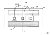
- FIG. 2 is a plan view of a first connector according to the first embodiment.
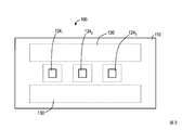
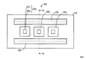
- FIG. The figure which shows the top view of the 2nd connector of Example 1.
- FIG. The figure which shows the rear view of the 2nd connector of Example 1.
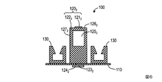
- FIG. The figure which shows sectional drawing of VI-VI of FIG.
- the figure which shows sectional drawing of VII-VII of FIG. The figure which shows sectional drawing in the position of VI-VI of FIG. 2 and VII-VII of FIG. 4 when the 1st connector of Example 1 and a 2nd connector are fitted.
- It shows a first example of a method for electrically connecting the first electrode 121 n and the conductor 123 n.
- FIG. 9 is a plan view of a first connector according to Embodiment 2. The figure which shows the rear view of the 1st connector of Example 2. FIG. The figure which shows the top view of the 2nd connector of Example 2 and Example 3. FIG. The figure which shows the rear view of the 2nd connector of Example 2 and Example 3. FIG. The figure which shows sectional drawing of XVI-XVI of FIG. The figure which shows sectional drawing of XVII-XVII of FIG.
- FIG. 9 is a plan view of a first connector according to Embodiment 3.
- FIG. The figure which shows sectional drawing of XXI-XXI of FIG.
- FIG. 2 is a plan view of the first connector of the first embodiment
- FIG. 3 is a rear view thereof.
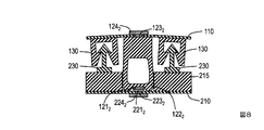
- the top view of the 2nd connector of Example 1 is shown in FIG. 4, and a rear view is shown in FIG. 6 is a sectional view taken along line VI-VI in FIG. 2, and FIG. 7 is a sectional view taken along line VII-VII in FIG. 8 is a cross-sectional view at the position of VI-VI in FIG. 2 and VII-VII in FIG. 4 when the first connector and the second connector of Example 1 are fitted.
- the first connector is upside down with respect to FIG.
- the connector assembly according to the first embodiment includes a first connector 100 and a second connector 200.
- “on the substrate” means not only the case of being directly arranged, but also the case of being indirectly arranged on the substrate by arranging another member therebetween (Examples 2 and 3). The same applies to
- At least one of the base material 110 of the first connector 100 and the base material 210 of the second connector 200 has flexibility. Both the base material 110 and the base material 210 may have flexibility.
- Examples of the material of the base material having flexibility include films of polyimide, polyester, polypropylene, polystyrene, polyethylene, vinyl chloride, and the like.
- Non-flexible base material materials include thermosetting plastics such as phenolic resin, epoxy, melamine, and polyurethane, general-purpose plastics such as polyethylene, Teflon (registered trademark), ABS resin, and acrylic resin, nylon polycarbonate, and liquid crystal polymer. There are engineering plastics.
- the first connector 100 and the second connector 200 further have engaging members 130 and 230 at positions facing each other.
- the engaging member 130 has a concave portion as shown in FIG. 6, and the engaging member 230 has a convex portion as shown in FIG. 8 is engaged.
- the engaging member 130 is disposed on the substrate 110, and the engaging member 230 is disposed on the recess forming portion 215.
- the unevenness of the engaging member may be reversed (the engaging member 230 may be disposed on the first connector 100 and the engaging member 130 may be disposed on the second connector 200). For example, if a resin fastener having such a shape is used as the engaging member, it can be easily attached and detached.
- thermoplastic resins such as low density polyethylene, ethylene- ⁇ olefin copolymer, ethylene-vinyl acetate copolymer, ethylene-acrylic acid copolymer, ethylene-acrylic acid ester copolymer may be used.
- resin what is necessary is just to fix to the base material 110 or the recessed part formation part 215 with an adhesive agent or heat sealing
- the resin fasteners are described in detail in Patent Documents 2 and 3 and the like.
- an engaging member having another shape such as a button may be used.
- the first electrical connection member 120 n includes a convex portion 122 n having elasticity, and a first electrode 121 n disposed at a tip end portion 126 n of the convex portion 122 n .
- the space 125 n is formed so that the convex part 122 n is hollow. By making it hollow, the convex portion 122 n is more easily deformed.
- the second electrical connection member 220 n includes a recess 222 n and a second electrode 221 n disposed on the bottom 226 n of the recess 222 n .
- the concave portion 222 n is formed by providing the concave portion forming portion 215 on the base material 210. As shown in FIG. 8, when the engagement members 130 and 230 are engaged, the first electrode 121 n and the second electrode 221 n are in contact with each other. Further, at least the convex portion 122 n is deformed, so that at least a part of the side surface 127 n of the convex portion 122 n comes into contact with the side surface 227 n of the concave portion 222 n over the entire circumference.
- the portion without the first electrode 121 n at the tip end 126 n of the convex portion 122 n and the portion without the second electrode 221 n at the bottom portion 226 n of the concave portion 222 n are the first electrode 121. contacts so as to surround the n second electrodes 221 n.
- water tightness is ensured by contacting the first electrode 121 n and the second electrode 221 n so as to surround the first electrode 121 n and the second electrode 221 n from the outside. May be prevented.
- the water tightness is ensured at two places, but only one may be used.
- the connector assembly embodiment 1 since the convex portion 122 n and the recess 222 n to ensure water-tightness by contacting, with a waterproof at least living environment.
- the concave portion 222 n When the convex portion 122 n is soft and watertightness can be ensured by contacting the convex portion 122 n and the concave portion 222 n when the engaging members 130 and 230 are engaged, the concave portion 222 n has elasticity. It does not have to be. However, if only the elasticity of the convex portion 122 n can not be ensured watertightness, it is sufficient be elasticized in the recess 222 n.
- the concave portion 222 n having elasticity means that the concave portion forming portion 215 has elasticity.
- the concave portion forming portion 215 and the convex portion 122 n include elastomer, polyurethane, polyester, polyamide, polystyrene, polyolefin, vinyl chloride, styrene-butadiene rubber, chlorobrene rubber, ethylene-propylene rubber silicon.
- a rubber material such as fluorine may be used.
- the above-described inflexible base material may be used, and the base 210 and the recess forming portion 215 may be formed integrally. Good.
- protrusion 122 n also recesses 222 n is rectangular, but the corners are clearly shown, protrusion 122 n may also have a rounded even angular recess 222 n. Further, the convex portion 122 n the distal end 126 n may have a generally rounded.
- the first electrode 121 n is electrically connected to the terminal 124 n through the conductor 123 n formed in the through hole of the base 110 by some method.
- 9 to 11 show an example of a method for electrically connecting the first electrode 121 n and the conductor 123 n .
- the first electrode 121 n and the conductor 123 n are connected by a plurality of thin conductive wires 141 n arranged in the convex portion 122 n .
- the thin conductive wire 141 n is a thin conducting wire that can be deformed along with the deformation of the convex portion 122 n .
- FIG. 9 show an example of a method for electrically connecting the first electrode 121 n and the conductor 123 n .
- the first electrode 121 n and the conductor 123 n are connected by a plurality of thin conductive wires 141 n arranged in the convex portion 122 n .
- the thin conductive wire 141 n is a
- FIG. 9 does not show the first electrode 121 n as shown in FIGS.
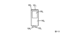
- the first electrode 121 n and the conductor 123 n are connected by a conductive rubber 142 n .
- the convex portion 122 n tip 126 n conductive rubber 142 n is exposed from the portion of (a portion surrounding by a dotted line) becomes the first electrode 121 n. Accordingly, FIG. 10 does not show the first electrode 121 n as shown in FIGS.
- FIG. 10 does not show the first electrode 121 n as shown in FIGS. In the example of FIG.
- the convex portion 122 n of the tip 126 n the formed conductive thin film 143 n is the first electrode 121 n.
- the method of electrically connecting the first electrode 121 n and the conductor 123 n need not be limited to the above three methods.
- the second electrode 221 n is electrically connected to the terminal 224 n through the conductor 223 n formed in the through hole of the base 210.
- a device attached to clothing or a body is connected to one of the terminal 124 n and the terminal 224 n, and the other is connected to an external measuring instrument or the like.
- the first electrical connecting member and the second electrical connecting member can be easily positioned and ensure water tightness, so that it has at least a waterproof property in a living environment.
- the example of the resin fastener is shown as the engaging member.
- the waterproofing property is not required for the engaging member, it may be appropriately selected according to the application.
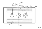
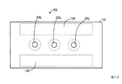
- FIG. 12 is a plan view of the first connector of the second embodiment, and FIG. 13 is a rear view thereof.
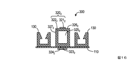
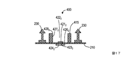
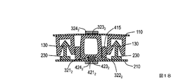
- the top view of the 2nd connector of Example 2 is shown in FIG. 14, and a rear view is shown in FIG. 16 is a cross-sectional view taken along XVI-XVI in FIG. 12, and FIG. 17 is a cross-sectional view taken along XVII-XVII in FIG. 18 is a cross-sectional view at the position of XVI-XVI in FIG. 12 and XVII-XVII in FIG. 14 when the first connector and the second connector of Example 2 are fitted.
- the first connector is upside down with respect to FIG.
- the connector assembly according to the second embodiment includes a first connector 300 and a second connector 400.
- the first electrical connection members 320 1 to 320 N and the second electrical connection members 420 1 to 420 N are cylindrical, and the engagement member 230 is disposed on the base 210.
- the width of the concave portion forming portion 415 is narrowed, and the height of the convex portions 322 1 to 322 N is low. Therefore, the thickness at the time of fitting can be made thinner than the connector assembly of the first embodiment.
- the base material 110 and the base material 210 are the same as those of the first embodiment, and the engaging members 130 and 230 are different only in that the engaging member 230 is disposed on the base material 210.
- the engaging member has water tightness. Therefore, an engaging member having another shape such as a button may be used.
- the first electrical connection member 320 n includes a convex portion 322 n having elasticity and a first electrode 321 n disposed at a tip portion 326 n of the convex portion 322 n .
- a space 325 n is formed so that the convex portion 322 n is hollow. By making it hollow, the convex portion 322 n is more easily deformed.
- the second electrical connection member 420 n includes a recess 422 n and a second electrode 421 n disposed on the bottom 426 n of the recess 422 n .
- the concave portion 422 n is formed by providing a concave portion forming portion 415 on the base material 210. As shown in FIG. 18, the first electrode 321 n and the second electrode 421 n are in contact with each other when the engaging members 130 and 230 are engaged. Further, at least the convex portion 322 n is deformed, so that at least a part of the side surface 327 n of the convex portion 322 n comes into contact with the side surface 427 n of the concave portion 422 n over the entire circumference.
- the connector assembly embodiment 2 since the convex portion 322 n and the recess 422 n to ensure water-tightness by contacting, with a waterproof at least living environment.
- the first electrode 321 n at the tip 326 n of the protrusion 322 n and the portion without the second electrode 421 n at the bottom 426 n of the recess 422 n are the first electrode. 321 n and may contact so as to surround the second electrode 421 n. Also, it may be also have an elastic recess 422 n.
- the convex portion 322 n may have a rounded end portion 326 n as a whole.
- the first electrode 321 n is electrically connected to the terminal 324 n through the conductor 323 n formed in the through hole of the base 110 by some method.
- a specific example of the method is the same as that of the first embodiment (FIGS. 9 to 11).
- the second electrode 421 n is electrically connected to the terminal 424 n via the conductor 423 n formed in the through hole of the substrate 210. Then, the device attached to the clothes and body are connected to one terminal 324 n and the terminal 424 n, the other is connected to an external instrument. Since the connector assembly of the second embodiment has such a configuration, the same effect as that of the connector assembly of the first embodiment can be obtained.
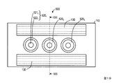
- FIG. 19 is a plan view of the first connector of Example 3, and FIG. 20 is a rear view thereof.
- the first connector is upside down with respect to FIG.
- the connector assembly according to the third embodiment includes a first connector 500 and a second connector 400.
- the second embodiment is different from the second embodiment in that the convex portion 522 n has a shape that becomes thinner as it approaches the tip portion 526 n .
- the base material 110 and the base material 210 are the same as those in the first embodiment, and the engaging members 130 and 230 are different from the first embodiment only in that the engaging member 230 is disposed on the base material 210.
- the engaging member has water tightness, and therefore an engaging member having another shape such as a button may be used.
- the first electrical connection member 520 n includes a convex portion 522 n that has a shape that becomes thinner toward the distal end portion and has elasticity, and a first electrode 521 n that is disposed at the distal end portion 526 n of the convex portion 522 n .
- the convex portion 522 n is not hollow, but a space may be formed in the convex portion 522 n as in the first and second embodiments.
- the second electrical connection member 420 n is the same as in the second embodiment.
- the first electrode 521 n and the second electrode 421 n are in contact.
- the opening portions 428 n sides 527 n and the recess 422 n of the protrusion 522 n contacts over the circumference. Since having at least a convex portion 522 n is an elastic, first electrode 521 n and the second electrode 421 n are in contact, and the opening portion 428 n sides 527 n and the recess 422 n of the protrusion 522 n is over the circumference Easy to contact.
- the connector assembly of Example 3 ensures watertightness by the contact between the convex portion 522 n and the concave portion 422 n, it has at least a waterproof property in a living environment.
- the first electrode 521 n of the tip 526 n of the protrusion 522 n and the portion of the bottom 426 n of the recess 422 n without the second electrode 421 n are the first electrode. 521 n and may contact so as to surround the second electrode 421 n. Also, it may be also have an elastic recess 422 n.
- the convex portion 522 n may have a rounded end portion 526 n as a whole.
- the first electrode 521 n is electrically connected to the terminal 324 n through a conductor 323 n formed in the through hole of the base 110 by some method.
- a specific example of the method is the same as that of the first embodiment (FIGS. 9 to 11).
- the second electrode 421 n is electrically connected to the terminal 424 n through the conductor 423 n formed in the through hole of the base 210.
- the device attached to the clothes and body are connected to one terminal 324 n and the terminal 424 n, the other is connected to an external instrument. Since the connector assembly of the third embodiment has such a configuration, the same effect as that of the connector assembly of the first embodiment can be obtained.
Landscapes
- Connector Housings Or Holding Contact Members (AREA)
- Coupling Device And Connection With Printed Circuit (AREA)
- Details Of Connecting Devices For Male And Female Coupling (AREA)
Abstract
本発明のコネクタ組立体は、基材(110)上に配列された第1電気接続部材(120)を有する第1コネクタ(100)と、基材(210)上に第1電気接続部材(120)と対向する位置に第2電気接続部材(220)を有する第2コネクタ(200)を備える。第1コネクタ(100)と第2コネクタ(200)はさらに、互いに対向する位置に、係合部材(130、2 30)を有する。第1電気接続部材(120)は、弾性を有する凸部(122)と凸部の先端部に配置された第1電極(121)を備える。第2電気接続部材(220)は、凹部(222)と凹部の底部に配置された第2電極(221)を備える。少なくとも第1コネクタの基材(110)と第2コネクタの基材(210)の一方は柔軟性を有する。そして、係合部材(130、230)を係合させた状態のときに、第1電極(121)と第2電極(221)が接触し、かつ凸部(122)と凹部(222)とが前記第1電極(121)と前記第2電極(221)の接触点への水の浸入を防ぐように接触する。
Description
本発明は、衣類や体などに取り付けるデバイスから電気信号を取り出すためのコネクタ組立体に関する。
衣類や体などに取り付けるデバイスから電気信号を取り出すためのコネクタとして、特許文献1の技術などが知られている。特許文献1の図2を図1に示す。また、特許文献1の要約には、課題として『装着感および耐久性を損なうことを防ぐことができるコネクタを提供する。』と記載され、解決手段として、『スナップボタン型コネクタは、導電性を有する第1の布1と、導電性を有する第2の布2と、第1の布1の他端と第2の布2の他端とを機械的および電気的に脱着可能に接続するスナップボタン3とを備える。このスナップボタン3は、第1の布1に機械的および電気的に接続され、導電性を有する材料からなる雄型スナップボタン4と、第2の布2に機械的および電気的に接続され、導電性を有する材料からなる雌型スナップボタン5とから構成される。』と記載されている。また、樹脂製のファスナの従来技術としては、特許文献2,3の技術などがある。
しかしながら、特許文献1の技術は、衣服や体などに取り付けるウエアラブルデバイス用コネクタにもかかわらず、電気接続部材が防滴構造(水滴の付着を防ぐ構造)になっていない。したがって、生活環境で付着する水滴などによって電気接続部材が劣化しやすいという課題がある。
本発明は、少なくとも生活環境での防水性を有するコネクタ組立体を提供することを目的とする。
本発明のコネクタ組立体は、基材上に配列された第1電気接続部材を有する第1コネクタと、基材上に前記第1電気接続部材と対向する位置に第2電気接続部材を有する第2コネクタを備える。第1コネクタと第2コネクタはさらに、互いに対向する位置に、係合部材を有する。第1電気接続部材は、弾性を有する凸部と凸部の先端部に配置された第1電極を備える。第2電気接続部材は、凹部と凹部の底部に配置された第2電極を備える。少なくとも第1コネクタの基材と第2コネクタの基材の一方は柔軟性を有する。そして、係合部材を係合させた状態のときに、第1電極と第2電極が接触し、かつ凸部と凹部とが前記第1電極と前記第2電極の接触点への水の浸入を防ぐように接触する。
本発明のコネクタ組立体によれば、第1電気接続部材と第2電気接続部材によって容易に位置決めと水密性確保ができるので、少なくとも生活環境での防水性を有する。
以下、本発明の実施の形態について、詳細に説明する。なお、同じ機能を有する構成部には同じ番号を付し、重複説明を省略する。
実施例1の第1コネクタの平面図を図2に、背面図を図3に示す。実施例1の第2コネクタの平面図を図4に、背面図を図5に示す。図6は図2のVI-VIの断面図、図7は図4のVII-VIIの断面図である。図8は、実施例1の第1コネクタと第2コネクタを嵌合したときの図2のVI-VIと図4のVII-VIIの位置での断面図である。なお、図8では、第1コネクタは図6とは上下が逆転している。
実施例1のコネクタ組立体は、第1コネクタ100と第2コネクタ200を備える。第1コネクタ100は、基材110上に配列された第1電気接続部材1201~120Nを有する(Nは1以上の整数であって、図2,3ではN=3)。第2コネクタ200は、基材210上に第1電気接続部材1201~120Nと対向する位置に第2電気接続部材2201~220Nを有する(図4,5ではN=3)。図2~5ではN=3であるが、これに限定する必要はなく、必要な数とすればよい。また、図6~8では、第1電気接続部材1201~120Nは基材110上に直接配置され、第2電気接続部材2201~220Nは基材210上に直接配置されている。ただし、「基材上」とは直接配置される場合だけでなく、間に別の部材を配置することで間接的に基材上に配置される場合も含む意味である(実施例2,3においても同じ)。
少なくとも第1コネクタ100の基材110と第2コネクタ200の基材210の一方は柔軟性を有する。基材110と基材210の両方が柔軟性を有してもよい。柔軟性を有する基材の材料としては、ポリイミド、ポリエステル、ポリピレン、ポリスチレン、ポリエチレン、塩化ビニルなどのフィルムなどがある。柔軟性の無い基材の材料としては、フェノール樹脂、エポキシ、メラミン、ポリウレタンなどの熱硬化プラスチック、ポリエチレン、テフロン(登録商標)、ABS樹脂、アクリル樹脂などの汎用プラスチック、ナイロンポリカーボネート、液晶ポリマなどのエンジニアリングプラスチックなどがある。
第1コネクタ100と第2コネクタ200はさらに、互いに対向する位置に、係合部材130,230を有する。図2~8に示した係合部材130,230の場合、図6に示すように係合部材130が凹部を有し、図7に示すように係合部材230が凸部を有し、図8に示すように係合される。この例では、係合部材130は基材110上に配置され、係合部材230は凹部形成部215上に配置されている。係合部材の凹凸は逆でもよい(係合部材230が第1コネクタ100に配置され、係合部材130が第2コネクタ200に配置されてもよい)。係合部材としては、例えばこのような形状の樹脂製のファスナを用いれば、着脱を簡単にできる。樹脂としては、低密度ポリエチレン、エチレン-αオレフィン共重合体、エチレン-酢酸ビニル共重合体、エチレン-アクリル酸共重合体、エチレン-アクリル酸エステル共重合体などの熱可塑性樹脂を用いればよい。また、樹脂の場合には、基材110や凹部形成部215に接着剤や熱融着によって固定すればよい。樹脂製のファスナに関しては特許文献2,3などに詳細に示されている。ただし、本願のコネクタ組立体では、係合部材が水密性を有することは必須の条件ではないので、ボタンなどの別の形状の係合部材でもよい。
図6~8を参照しながら第1電気接続部材120nと第2電気接続部材220nについて説明する(nは1以上N以下の整数であって、図6~8ではn=2)。第1電気接続部材120nは、弾性を有する凸部122nと、凸部122nの先端部126nに配置された第1電極121nを備える。図6の例では、凸部122nは中空となるように、空間125nが形成されている。中空とすることで、凸部122nはより変形しやすくなる。第2電気接続部材220nは、凹部222nと凹部222nの底部226nに配置された第2電極221nを備える。凹部222nは、基材210上に凹部形成部215を設けることで形成されている。図8に示すように係合部材130,230を係合させた状態のときに、第1電極121nと第2電極221nが接触する。また、少なくとも凸部122nが変形することで、凸部122nの側面127nの少なくとも一部が凹部222nの側面227nに一周に渡って接触する。これによって、水密性が確保され、外部から第1電極121nと第2電極221nの接触点への水の浸入を防ぐことができる。図8の例では、さらに、凸部122nの先端部126nの第1電極121nの無い部分と凹部222nの底部226nの第2電極221nの無い部分とが、第1電極121nと第2電極221nを囲むように接触している。このように、第1電極121nと第2電極221nを囲むように接触することで水密性を確保し、外部から第1電極121nと第2電極221nの接触点への水の浸入を防いでもよい。図8の例では、2つの場所で水密性を確保したが、片方だけでもよい。このように、実施例1のコネクタ組立体は、凸部122nと凹部222nとが接触することで水密性を確保するので、少なくとも生活環境での防水性を有する。
凸部122nが柔らかく、係合部材130,230を係合させたときに凸部122nと凹部222nとが接触することで水密性を確保できる場合は、凹部222nは弾性を有さなくてもよい。しかし、凸部122nの弾性だけでは水密性を確保できない場合は、凹部222nにも弾性を持たせればよい。なお、凹部222nが弾性を有するとは、凹部形成部215が弾性を有することを意味している。凹部222nが弾性を有する場合の凹部形成部215と凸部122nには、エラストマー、ポリウレタン、ポリエステル、ポリアミド、ポリスチレン、ポリオレフィン、塩化ビニル、スチレン-ブタジエンゴム、クロロブレンゴム、エチレン-プロピレンゴムシリコン、フッ素等のゴム材料などを用いればよい。凹部222nが弾性を有さない場合の凹部形成部215には、上述の柔軟性の無い基材の材料を用いればよく、基材210と凹部形成部215とを一体的に形成してもよい。図2~8では凸部122nも凹部222nも矩形であり、角が明確に示されているが、凸部122nも凹部222nも角に丸みを有してもよい。また、凸部122nは先端部126nが全体的に丸みを有してもよい。
図6,8には図示していないが、第1電極121nは何らかの方法で基材110のスルーホールに形成された導体123nを介して端子124nと電気的に接続される。図9~11に、第1電極121nと導体123nとを電気的に接続する方法の例を示す。図9の例では、第1電極121nと導体123nとは凸部122n内に配置された複数の導電細線141nで接続される。導電細線141nは凸部122nの変形に伴って変形できるような細い導線である。なお、図9の例の場合、凸部122nの先端部126nから導電細線141nが露出した部分(点線で囲んでいる部分)が第1電極121nとなる。したがって、図9には、図6,8に示したような第1電極121nは図示されていない。図10の例では、第1電極121nと導体123nとは導電性ゴム142nで接続される。図10の例の場合、凸部122nの先端部126nから導電性ゴム142nが露出した部分(点線で囲んでいる部分)が第1電極121nとなる。したがって、図10にも、図6,8に示したような第1電極121nは図示されていない。図11の例では、凸部122nの外周に形成された導電性薄膜143nで接続される。図11の例の場合、凸部122nの先端部126nに形成された導電性薄膜143nが第1電極121nとなる。第1電極121nと導体123nとを電気的に接続する方法は、上述の3つの方法に限定する必要はない。また、図7,8に示しているように、第2電極221nは基材210のスルーホールに形成された導体223nを介して端子224nと電気的に接続される。そして、端子124nと端子224nの一方に衣類や体などに取り付けるデバイスが接続され、他方が外部の計測器などに接続される。
実施例1のコネクタ組立体によれば、第1電気接続部材と第2電気接続部材によって容易に位置決めと水密性確保ができるので、少なくとも生活環境での防水性を有する。また、実施例では係合部材として樹脂製のファスナの例を示したが、係合部材には防水性は求められないので、用途に合わせて適宜選択すればよい。
実施例2の第1コネクタの平面図を図12に、背面図を図13に示す。実施例2の第2コネクタの平面図を図14に、背面図を図15に示す。図16は図12のXVI-XVIの断面図、図17は図14のXVII-XVIIの断面図である。図18は、実施例2の第1コネクタと第2コネクタを嵌合したときの図12のXVI-XVIと図14のXVII-XVIIの位置での断面図である。なお、図18では、第1コネクタは図16とは上下が逆転している。
実施例2のコネクタ組立体は、第1コネクタ300と第2コネクタ400を備える。第1コネクタ300は、基材110上に配列された第1電気接続部材3201~320Nを有する(Nは1以上の整数であって、図12,13ではN=3)。第2コネクタ400は、基材210上に第1電気接続部材3201~320Nと対向する位置に第2電気接続部材4201~420Nを有する(図14,15ではN=3)。図12~15ではN=3であるが、これに限定する必要はなく、必要な数とすればよい。実施例1とは、第1電気接続部材3201~320Nと第2電気接続部材4201~420Nが円柱状である点と、係合部材230が基材210上に配置されている点が異なる。この違いのために、凹部形成部415の幅が狭くなり、凸部3221~322Nの高さが低くなっている。したがって、実施例1のコネクタ組立体よりも嵌合時の厚さを薄くできる。
基材110と基材210については実施例1と同じであり、係合部材130,230については、係合部材230が基材210上に配置されている点のみが異なる。なお、実施例2の場合も係合部材が水密性を有することは必須の条件ではないので、ボタンなどの別の形状の係合部材でもよい。
図16~18を参照しながら第1電気接続部材320nと第2電気接続部材420nについて説明する(nは1以上N以下の整数であって、図16~18ではn=2)。第1電気接続部材320nは、弾性を有する凸部322nと、凸部322nの先端部326nに配置された第1電極321nを備える。図16の例では、凸部322nは中空となるように、空間325nが形成されている。中空とすることで、凸部322nはより変形しやすくなる。第2電気接続部材420nは、凹部422nと凹部422nの底部426nに配置された第2電極421nを備える。凹部422nは、基材210上に凹部形成部415を設けることで形成されている。図18に示すように係合部材130,230を係合させた状態のときに、第1電極321nと第2電極421nが接触する。また、少なくとも凸部322nが変形することで、凸部322nの側面327nの少なくとも一部が凹部422nの側面427nに一周に渡って接触する。これによって、水密性が確保され、外部から第1電極321nと第2電極421nの接触点への水の浸入を防ぐことができる。このように、実施例2のコネクタ組立体は、凸部322nと凹部422nとが接触することで水密性を確保するので、少なくとも生活環境での防水性を有する。なお、実施例1のように、凸部322nの先端部326nの第1電極321nの無い部分と凹部422nの底部426nの第2電極421nの無い部分とが、第1電極321nと第2電極421nを囲むように接触するようにしてもよい。また、凹部422nにも弾性を持たせてもよい。また、凸部322nは先端部326nが全体的に丸みを有してもよい。
第1電極321nは何らかの方法で基材110のスルーホールに形成された導体323nを介して端子324nと電気的に接続される。具体的な方法の例は実施例1(図9~11)と同じである。また、図17,18に示しているように、第2電極421nは基材210のスルーホールに形成された導体423nを介して端子424nと電気的に接続される。そして、端子324nと端子424nの一方に衣類や体などに取り付けるデバイスが接続され、他方が外部の計測器などに接続される。実施例2のコネクタ組立体はこのような構成なので、実施例1のコネクタ組立体と同様の効果が得られる。
実施例3の第1コネクタの平面図を図19に、背面図を図20に示す。実施例3の第2コネクタの平面図を図14に、背面図を図15に示す。図21は図19のXXI-XXIの断面図である。図22は、実施例3の第1コネクタと第2コネクタを嵌合したときの図19のXXI-XXIと図14のXVII-XVIIの位置での断面図である。なお、図22では、第1コネクタは図21とは上下が逆転している。
実施例3のコネクタ組立体は、第1コネクタ500と第2コネクタ400を備える。第1コネクタ500は、基材110上に配列された第1電気接続部材5201~520Nを有する(Nは1以上の整数であって、図19,20ではN=3)。第2コネクタ400は、実施例2と同じである。図14,15,19,20ではN=3であるが、これに限定する必要はなく、必要な数とすればよい。実施例2とは、凸部522nが先端部526nに近づくほど細くなる形状である点が異なる。
基材110と基材210については実施例1と同じであり、係合部材130,230については、係合部材230が基材210上に配置されている点のみが実施例1と異なる。なお、実施例3の場合も係合部材が水密性を有することは必須の条件ではないので、ボタンなどの別の形状の係合部材でもよい。
図17,21,22を参照しながら第1電気接続部材520nと第2電気接続部材420nについて説明する(nは1以上N以下の整数であって、図17,21,22ではn=2)。第1電気接続部材520nは、先端部ほど細くなる形状であって弾性を有する凸部522nと、凸部522nの先端部526nに配置された第1電極521nを備える。図21の例では、凸部522nは中空にしていないが、実施例1,2のように凸部522nの中に空間を形成してもよい。第2電気接続部材420nは、実施例2と同じである。図22に示すように係合部材130,230を係合させた状態のときに、第1電極521nと第2電極421nが接触する。また、凸部522nの側面527nと凹部422nの開口部分428nとが一周に渡って接触する。少なくとも凸部522nが弾性を有するので、第1電極521nと第2電極421nが接触し、かつ凸部522nの側面527nと凹部422nの開口部分428nとが一周に渡って接触する状態にしやすい。これによって、水密性が確保され、外部から第1電極521nと第2電極421nの接触点への水の浸入を防ぐことができる。このように、実施例3のコネクタ組立体は、凸部522nと凹部422nとが接触することで水密性を確保するので、少なくとも生活環境での防水性を有する。なお、実施例1のように、凸部522nの先端部526nの第1電極521nの無い部分と凹部422nの底部426nの第2電極421nの無い部分とが、第1電極521nと第2電極421nを囲むように接触するようにしてもよい。また、凹部422nにも弾性を持たせてもよい。また、凸部522nは先端部526nが全体的に丸みを有してもよい。
第1電極521nは何らかの方法で基材110のスルーホールに形成された導体323nを介して端子324nと電気的に接続される。具体的な方法の例は実施例1(図9~11)と同じである。また、図17,22に示しているように、第2電極421nは基材210のスルーホールに形成された導体423nを介して端子424nと電気的に接続される。そして、端子324nと端子424nの一方に衣類や体などに取り付けるデバイスが接続され、他方が外部の計測器などに接続される。実施例3のコネクタ組立体はこのような構成なので、実施例1のコネクタ組立体と同様の効果が得られる。
100,300,500 第1コネクタ
110,210 基材
120,320,520 第1電気接続部材
121,321,521 第1電極
122,322,522 凸部
123,223,323,423 導体
124,224,324,424 端子
125,325 空間
126,326,526 先端部
127,227,327,427,527 側面
130,230 係合部材
141 導電細線
142 導電性ゴム
143 導電性薄膜
200,400 第2コネクタ
215,415 凹部形成部
220,420 第2電気接続部材
221,421 第2電極
222,422 凹部
223,423 導体
226,426 底部
428 開口部分
110,210 基材
120,320,520 第1電気接続部材
121,321,521 第1電極
122,322,522 凸部
123,223,323,423 導体
124,224,324,424 端子
125,325 空間
126,326,526 先端部
127,227,327,427,527 側面
130,230 係合部材
141 導電細線
142 導電性ゴム
143 導電性薄膜
200,400 第2コネクタ
215,415 凹部形成部
220,420 第2電気接続部材
221,421 第2電極
222,422 凹部
223,423 導体
226,426 底部
428 開口部分
Claims (8)
- 基材上に配列された第1電気接続部材を有する第1コネクタと、
基材上に前記第1電気接続部材と対向する位置に第2電気接続部材を有する第2コネクタを備えるコネクタ組立体であって、
前記第1コネクタと前記第2コネクタはさらに、互いに対向する位置に、係合部材を有し、
前記第1電気接続部材は、弾性を有する凸部と前記凸部の先端部に配置された第1電極を備え、
前記第2電気接続部材は、凹部と前記凹部の底部に配置された第2電極を備え、
少なくとも前記第1コネクタの基材と前記第2コネクタの基材の一方は柔軟性を有し、
前記係合部材を係合させた状態のときに、前記第1電極と前記第2電極が接触し、かつ前記凸部と前記凹部とが前記第1電極と前記第2電極の接触点への水の浸入を防ぐように接触する
ことを特徴とするコネクタ組立体。 - 基材上に配列された第1電気接続部材を有する第1コネクタと、
基材上に前記第1電気接続部材と対向する位置に第2電気接続部材を有する第2コネクタを備えるコネクタ組立体であって、
前記第1コネクタと前記第2コネクタはさらに、互いに対向する位置に、係合部材を有し、
前記第1電気接続部材は、弾性を有する凸部と前記凸部の先端部に配置された第1電極を備え、
前記第2電気接続部材は、凹部と前記凹部の底部に配置された第2電極を備え、
少なくとも前記第1コネクタの基材と前記第2コネクタの基材の一方は柔軟性を有し、
前記係合部材を係合させた状態のときに、前記第1電極と前記第2電極が接触し、かつ、前記凸部の側面の少なくとも一部が前記凹部の側面に一周に渡って接触する
ことを特徴とするコネクタ組立体。 - 基材上に配列された第1電気接続部材を有する第1コネクタと、
基材上に前記第1電気接続部材と対向する位置に第2電気接続部材を有する第2コネクタを備えるコネクタ組立体であって、
前記第1コネクタと前記第2コネクタはさらに、互いに対向する位置に、係合部材を有し、
前記第1電気接続部材は、弾性を有する凸部と前記凸部の先端部の一部に配置された第1電極を備え、
前記第2電気接続部材は、凹部と前記凹部の底部の一部に配置された第2電極を備え、
少なくとも前記第1コネクタの基材と前記第2コネクタの基材の一方は柔軟性を有し、
前記係合部材を係合させた状態のときに、前記第1電極と前記第2電極が接触し、かつ、前記凸部の先端部の前記第1電極の無い部分と前記凹部の底部の前記第2電極の無い部分とが前記第1電極と第2電極を囲むように接触する
ことを特徴とするコネクタ組立体。 - 基材上に配列された第1電気接続部材を有する第1コネクタと、
基材上に前記第1電気接続部材と対向する位置に第2電気接続部材を有する第2コネクタを備えるコネクタ組立体であって、
前記第1コネクタと前記第2コネクタはさらに、互いに対向する位置に、係合部材を有し、
前記第1電気接続部材は、先端部ほど細くなる形状であって弾性を有する凸部と、前記凸部の先端部に配置された第1電極を備え、
前記第2電気接続部材は、凹部と前記凹部の底部に配置された第2電極を備え、少なくとも前記第1コネクタの基材と前記第2コネクタの基材の一方は柔軟性を有し、
前記係合部材を係合させた状態のときに、前記第1電極と前記第2電極が接触し、前記凸部の側面と前記凹部の開口部分とが一周に渡って接触する
ことを特徴とするコネクタ組立体。 - 請求項1~4のいずれかに記載のコネクタ組立体であって、
前記凹部も弾性を有する
ことを特徴とするコネクタ組立体。 - 請求項1~5のいずれかに記載のコネクタ組立体であって、
前記第1コネクタの基材と前記第2コネクタの基材の両方が柔軟性を有する
ことを特徴とするコネクタ組立体。 - 請求項1~6のいずれかに記載のコネクタ組立体であって、
前記凸部は中空である
ことを特徴とするコネクタ組立体。 - 請求項1~7のいずれかに記載のコネクタ組立体であって、
前記係合部材は、樹脂製のファスナである
ことを特徴とするコネクタ組立体。
Priority Applications (2)
| Application Number | Priority Date | Filing Date | Title |
|---|---|---|---|
| CN201780052718.7A CN109643870B (zh) | 2016-10-13 | 2017-06-05 | 连接器组件 |
| US16/332,945 US11075482B2 (en) | 2016-10-13 | 2017-06-05 | Water-resistant electrical connector assembly |
Applications Claiming Priority (2)
| Application Number | Priority Date | Filing Date | Title |
|---|---|---|---|
| JP2016201647A JP6199467B1 (ja) | 2016-10-13 | 2016-10-13 | コネクタ組立体 |
| JP2016-201647 | 2016-10-13 |
Publications (1)
| Publication Number | Publication Date |
|---|---|
| WO2018070073A1 true WO2018070073A1 (ja) | 2018-04-19 |
Family
ID=59895686
Family Applications (1)
| Application Number | Title | Priority Date | Filing Date |
|---|---|---|---|
| PCT/JP2017/020745 Ceased WO2018070073A1 (ja) | 2016-10-13 | 2017-06-05 | コネクタ組立体 |
Country Status (4)
| Country | Link |
|---|---|
| US (1) | US11075482B2 (ja) |
| JP (1) | JP6199467B1 (ja) |
| CN (1) | CN109643870B (ja) |
| WO (1) | WO2018070073A1 (ja) |
Families Citing this family (2)
| Publication number | Priority date | Publication date | Assignee | Title |
|---|---|---|---|---|
| JP6199471B1 (ja) | 2016-10-31 | 2017-09-20 | 日本航空電子工業株式会社 | コネクタ組立体 |
| FI20206359A1 (en) * | 2020-12-22 | 2022-06-23 | Suunto Oy | Female snap connectors and associated devices and methods |
Citations (5)
| Publication number | Priority date | Publication date | Assignee | Title |
|---|---|---|---|---|
| JPS512301Y1 (ja) * | 1970-05-13 | 1976-01-23 | ||
| JPH0729758U (ja) * | 1993-11-04 | 1995-06-02 | 株式会社東海理化電機製作所 | コネクタ |
| JP2004241187A (ja) * | 2003-02-04 | 2004-08-26 | Alps Electric Co Ltd | コネクタ及びコネクタの接続方法 |
| JP2008091091A (ja) * | 2006-09-29 | 2008-04-17 | Casio Hitachi Mobile Communications Co Ltd | 電子機器 |
| JP2016097273A (ja) * | 2014-11-26 | 2016-05-30 | 日本電信電話株式会社 | 固定用部品 |
Family Cites Families (21)
| Publication number | Priority date | Publication date | Assignee | Title |
|---|---|---|---|---|
| JPS543765Y2 (ja) | 1974-06-21 | 1979-02-21 | ||
| US5197892A (en) * | 1988-05-31 | 1993-03-30 | Canon Kabushiki Kaisha | Electric circuit device having an electric connecting member and electric circuit components |
| DE4402837C2 (de) * | 1994-01-31 | 1998-08-06 | Daetwyler Ag | Elektrisches Installationssystem, gebildet durch Flachkabel und Anschlußvorrichtung |
| JP4133141B2 (ja) * | 2002-09-10 | 2008-08-13 | 株式会社エンプラス | 電気部品用ソケット |
| US7014479B2 (en) * | 2003-03-24 | 2006-03-21 | Che-Yu Li | Electrical contact and connector and method of manufacture |
| JP4530404B2 (ja) | 2004-02-12 | 2010-08-25 | 旭化成パックス株式会社 | ファスナー付き包装材料および包装体 |
| JP2006055280A (ja) | 2004-08-18 | 2006-03-02 | Idemitsu Unitech Co Ltd | 嵌合ファスナー及びファスナー付き袋 |
| JP4240499B2 (ja) * | 2006-02-09 | 2009-03-18 | 日本航空電子工業株式会社 | 接続部材 |
| DE102011006867A1 (de) * | 2011-04-06 | 2012-10-11 | Robert Bosch Gmbh | Steckverbinder zur Direktkontaktierung auf einer Leiterplatte |
| US10130550B2 (en) * | 2012-03-14 | 2018-11-20 | Ralph Zipper | Sexual stimulation device using light therapy, vibration and physiological feedback |
| JP2015065147A (ja) * | 2013-08-29 | 2015-04-09 | アルプス電気株式会社 | 電子部品用ソケット |
| JP2015135723A (ja) | 2014-01-16 | 2015-07-27 | 日本電信電話株式会社 | スナップボタン型コネクタ |
| US10418145B2 (en) * | 2014-06-06 | 2019-09-17 | President And Fellows Of Harvard College | Stretchable conductive composites for use in soft devices |
| CN204045832U (zh) | 2014-08-20 | 2014-12-24 | 陈余川 | 一种防水连接器 |
| US9627804B2 (en) * | 2014-12-19 | 2017-04-18 | Intel Corporation | Snap button fastener providing electrical connection |
| WO2017109788A1 (en) * | 2015-12-23 | 2017-06-29 | Fidmi Medical Ltd. | Devices and methods for ports to living tissue and/or lumens and related procedures |
| ES1154983Y (es) * | 2016-03-23 | 2016-07-18 | Barquero Bartolome Lajarin | Dispositivo de aguja para bloqueo nervioso |
| US10455922B2 (en) * | 2016-06-01 | 2019-10-29 | Tyr Tactical, Llc | Load carriage frame |
| JP6748517B2 (ja) | 2016-08-25 | 2020-09-02 | 日本航空電子工業株式会社 | コネクタ組立体 |
| JP6199471B1 (ja) * | 2016-10-31 | 2017-09-20 | 日本航空電子工業株式会社 | コネクタ組立体 |
| CN110011136B (zh) * | 2019-03-11 | 2020-09-25 | 番禺得意精密电子工业有限公司 | 连接器组合 |
-
2016
- 2016-10-13 JP JP2016201647A patent/JP6199467B1/ja active Active
-
2017
- 2017-06-05 US US16/332,945 patent/US11075482B2/en active Active
- 2017-06-05 CN CN201780052718.7A patent/CN109643870B/zh active Active
- 2017-06-05 WO PCT/JP2017/020745 patent/WO2018070073A1/ja not_active Ceased
Patent Citations (5)
| Publication number | Priority date | Publication date | Assignee | Title |
|---|---|---|---|---|
| JPS512301Y1 (ja) * | 1970-05-13 | 1976-01-23 | ||
| JPH0729758U (ja) * | 1993-11-04 | 1995-06-02 | 株式会社東海理化電機製作所 | コネクタ |
| JP2004241187A (ja) * | 2003-02-04 | 2004-08-26 | Alps Electric Co Ltd | コネクタ及びコネクタの接続方法 |
| JP2008091091A (ja) * | 2006-09-29 | 2008-04-17 | Casio Hitachi Mobile Communications Co Ltd | 電子機器 |
| JP2016097273A (ja) * | 2014-11-26 | 2016-05-30 | 日本電信電話株式会社 | 固定用部品 |
Also Published As
| Publication number | Publication date |
|---|---|
| US11075482B2 (en) | 2021-07-27 |
| US20190252825A1 (en) | 2019-08-15 |
| CN109643870B (zh) | 2020-12-18 |
| CN109643870A (zh) | 2019-04-16 |
| JP6199467B1 (ja) | 2017-09-20 |
| JP2018063855A (ja) | 2018-04-19 |
Similar Documents
| Publication | Publication Date | Title |
|---|---|---|
| JP6826878B2 (ja) | スライド型コネクタ | |
| US9812812B2 (en) | Snap button connector | |
| US10923855B2 (en) | Connector to prevent misconnection of contacts without the use of a projection and a groove | |
| TWI738897B (zh) | 電連接器 | |
| JPWO2009090998A1 (ja) | フレキシブル基板用防水コネクタ | |
| US10461466B2 (en) | Connector assembly | |
| TW201916505A (zh) | 連接器及連接器組裝體 | |
| JP6199467B1 (ja) | コネクタ組立体 | |
| JP6199471B1 (ja) | コネクタ組立体 | |
| US9288925B2 (en) | Electrical connector and electronic device having the same | |
| KR102210023B1 (ko) | 커넥터 어셈블리 | |
| JP2004119294A (ja) | シール材の固定構造 | |
| JP2011086457A (ja) | 防水コネクタ | |
| TWM577605U (zh) | Connector | |
| US20200212625A1 (en) | Electrical Connector | |
| US20240250461A1 (en) | Connector | |
| CN209133719U (zh) | 连接器 | |
| JP2004158338A (ja) | 電子部品の防水構造 | |
| JP2002190346A (ja) | 防水用コネクタ装置 | |
| TWM364326U (en) | Electrical connector | |
| KR20170034664A (ko) | 플렉시블 커넥터 | |
| TWM519827U (zh) | 電連接器 |
Legal Events
| Date | Code | Title | Description |
|---|---|---|---|
| 121 | Ep: the epo has been informed by wipo that ep was designated in this application |
Ref document number: 17860473 Country of ref document: EP Kind code of ref document: A1 |
|
| NENP | Non-entry into the national phase |
Ref country code: DE |
|
| 122 | Ep: pct application non-entry in european phase |
Ref document number: 17860473 Country of ref document: EP Kind code of ref document: A1 |