WO2018061521A1 - 通信装置及び通信方法 - Google Patents
通信装置及び通信方法 Download PDFInfo
- Publication number
- WO2018061521A1 WO2018061521A1 PCT/JP2017/029753 JP2017029753W WO2018061521A1 WO 2018061521 A1 WO2018061521 A1 WO 2018061521A1 JP 2017029753 W JP2017029753 W JP 2017029753W WO 2018061521 A1 WO2018061521 A1 WO 2018061521A1
- Authority
- WO
- WIPO (PCT)
- Prior art keywords
- communication
- base station
- data
- terminal
- remote terminal
- Prior art date
Links
Images


Classifications
-
- H—ELECTRICITY
- H04—ELECTRIC COMMUNICATION TECHNIQUE
- H04L—TRANSMISSION OF DIGITAL INFORMATION, e.g. TELEGRAPHIC COMMUNICATION
- H04L1/00—Arrangements for detecting or preventing errors in the information received
- H04L1/12—Arrangements for detecting or preventing errors in the information received by using return channel
- H04L1/16—Arrangements for detecting or preventing errors in the information received by using return channel in which the return channel carries supervisory signals, e.g. repetition request signals
- H04L1/18—Automatic repetition systems, e.g. Van Duuren systems
- H04L1/1829—Arrangements specially adapted for the receiver end
- H04L1/1861—Physical mapping arrangements
-
- H—ELECTRICITY
- H04—ELECTRIC COMMUNICATION TECHNIQUE
- H04B—TRANSMISSION
- H04B17/00—Monitoring; Testing
- H04B17/20—Monitoring; Testing of receivers
- H04B17/24—Monitoring; Testing of receivers with feedback of measurements to the transmitter
-
- H—ELECTRICITY
- H04—ELECTRIC COMMUNICATION TECHNIQUE
- H04B—TRANSMISSION
- H04B17/00—Monitoring; Testing
- H04B17/30—Monitoring; Testing of propagation channels
- H04B17/382—Monitoring; Testing of propagation channels for resource allocation, admission control or handover
-
- H—ELECTRICITY
- H04—ELECTRIC COMMUNICATION TECHNIQUE
- H04L—TRANSMISSION OF DIGITAL INFORMATION, e.g. TELEGRAPHIC COMMUNICATION
- H04L5/00—Arrangements affording multiple use of the transmission path
- H04L5/003—Arrangements for allocating sub-channels of the transmission path
- H04L5/0053—Allocation of signaling, i.e. of overhead other than pilot signals
- H04L5/0055—Physical resource allocation for ACK/NACK
-
- H—ELECTRICITY
- H04—ELECTRIC COMMUNICATION TECHNIQUE
- H04W—WIRELESS COMMUNICATION NETWORKS
- H04W24/00—Supervisory, monitoring or testing arrangements
- H04W24/10—Scheduling measurement reports ; Arrangements for measurement reports
-
- H—ELECTRICITY
- H04—ELECTRIC COMMUNICATION TECHNIQUE
- H04W—WIRELESS COMMUNICATION NETWORKS
- H04W28/00—Network traffic management; Network resource management
- H04W28/02—Traffic management, e.g. flow control or congestion control
- H04W28/04—Error control
-
- H—ELECTRICITY
- H04—ELECTRIC COMMUNICATION TECHNIQUE
- H04W—WIRELESS COMMUNICATION NETWORKS
- H04W72/00—Local resource management
- H04W72/50—Allocation or scheduling criteria for wireless resources
- H04W72/54—Allocation or scheduling criteria for wireless resources based on quality criteria
- H04W72/542—Allocation or scheduling criteria for wireless resources based on quality criteria using measured or perceived quality
-
- H—ELECTRICITY
- H04—ELECTRIC COMMUNICATION TECHNIQUE
- H04W—WIRELESS COMMUNICATION NETWORKS
- H04W92/00—Interfaces specially adapted for wireless communication networks
- H04W92/16—Interfaces between hierarchically similar devices
- H04W92/18—Interfaces between hierarchically similar devices between terminal devices
-
- H—ELECTRICITY
- H04—ELECTRIC COMMUNICATION TECHNIQUE
- H04L—TRANSMISSION OF DIGITAL INFORMATION, e.g. TELEGRAPHIC COMMUNICATION
- H04L1/00—Arrangements for detecting or preventing errors in the information received
- H04L1/12—Arrangements for detecting or preventing errors in the information received by using return channel
- H04L1/16—Arrangements for detecting or preventing errors in the information received by using return channel in which the return channel carries supervisory signals, e.g. repetition request signals
- H04L1/1607—Details of the supervisory signal
-
- H—ELECTRICITY
- H04—ELECTRIC COMMUNICATION TECHNIQUE
- H04L—TRANSMISSION OF DIGITAL INFORMATION, e.g. TELEGRAPHIC COMMUNICATION
- H04L1/00—Arrangements for detecting or preventing errors in the information received
- H04L2001/0092—Error control systems characterised by the topology of the transmission link
- H04L2001/0097—Relays
-
- H—ELECTRICITY
- H04—ELECTRIC COMMUNICATION TECHNIQUE
- H04W—WIRELESS COMMUNICATION NETWORKS
- H04W88/00—Devices specially adapted for wireless communication networks, e.g. terminals, base stations or access point devices
- H04W88/02—Terminal devices
- H04W88/04—Terminal devices adapted for relaying to or from another terminal or user
Definitions
- the present disclosure relates to a communication device and a communication method.
- IoT Internet of Things
- 3GPP is standardizing communication methods specialized for IoT terminals such as MTC (Machine Type Communication) and NB-IoT (Narrow Band IoT).
- MTC Machine Type Communication
- NB-IoT Narrow Band IoT
- a typical example of a low cost terminal is a so-called wearable terminal.
- wearable terminals low power consumption and highly reliable communication are required, and large-capacity communication may be required depending on the situation.
- standardization of FeD2D was started in 2016 in 3GPP. Since wearable terminals exist in the vicinity of users themselves, using relay communication using a terminal device such as a smartphone can shorten the communication distance and achieve low power consumption and highly reliable communication. It becomes possible.
- An example of relay communication based on an existing standard is disclosed in Patent Document 1, for example.
- relay terminal such as a smartphone
- the presence of a relay terminal that relays communication between a so-called remote terminal and a base station is important.
- radio link communication hereinafter also referred to as “backhaul link communication”
- access link communication The communication quality of each of the wireless link communication (hereinafter also referred to as “access link communication”) with a terminal device connected to the terminal (so-called remote terminal) is managed independently.
- the present disclosure proposes a communication device and a communication method capable of guaranteeing the quality of a radio link end-to-end in relay communication between a base station and a remote terminal via a relay terminal.
- a communication unit that performs wireless communication, and information regarding a remote terminal connected to a relay terminal configured to be movable via a first wireless link are acquired, and the acquired information regarding the remote terminal is acquired.
- a communication processing unit that allocates a resource for acquiring a data reception result from the relay terminal via the second wireless link to the second wireless link with the relay terminal.
- the communication unit that performs wireless communication and the information about the remote terminal connected via the first wireless link are notified to the base station connected via the second wireless link, After the notification, a communication device is provided that includes a notification unit that notifies a base station of a data reception result using a resource allocated to the second radio link.
- information on data transmission / reception via a wireless link between a communication unit that performs wireless communication and a relay terminal configured to be movable can be transmitted to the remote terminal and the relay terminal.
- a communication processing unit that controls direct or indirect communication with the remote terminal corresponding to the information after acquiring information on transmission / reception of the data.
- information regarding data transmission / reception via a wireless link between a communication unit that performs wireless communication and a relay terminal configured to be movable can be directly transmitted to a base station.
- a communication device including a notification unit that indirectly notifies is provided.
- the computer acquires information related to the remote terminal connected via the first wireless link to the relay terminal configured to perform wireless communication and to be movable, and the acquired remote Allocating resources for acquiring a data reception result from the relay terminal via the second radio link to the second radio link with the relay terminal based on information on the terminal;
- a communication method is provided.
- the computer notifies the base station connected via the second wireless link of performing wireless communication and information regarding the remote terminal connected via the first wireless link. And after the said notification, using the resource allocated to the said 2nd radio
- information related to data transmission / reception via a wireless link between a remote terminal and a relay terminal configured to be movable can be transmitted between the remote terminal and the computer.
- Obtaining direct information or indirect communication with the remote terminal corresponding to the information after obtaining information on transmission / reception of the data, from at least one of the relay terminals A communication method is provided.
- information related to transmission / reception of data via a wireless link between a remote terminal and a relay terminal configured to be movable can be transmitted to a base station by a computer.
- a communication method including direct or indirect notification.
- a communication apparatus and a communication method capable of guaranteeing the quality of a radio link end-to-end in relay communication between a base station and a remote terminal via a relay terminal. Is done.
- FIG. 2 is an explanatory diagram for describing an example of a schematic configuration of a system according to an embodiment of the present disclosure.
- FIG. It is explanatory drawing for demonstrating the outline
- FIG. 2 is an explanatory diagram for describing an overview of a system according to a first embodiment of the present disclosure.
- FIG. It is the sequence diagram which showed an example of the flow of a series of processes of the relay communication in the system which concerns on the embodiment. It is explanatory drawing for demonstrating the outline
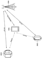
- FIG. 1 is an explanatory diagram for describing an example of a schematic configuration of a system 1 according to an embodiment of the present disclosure.
- the system 1 includes a wireless communication device 100 and a terminal device 200.
- the terminal device 200 is also called a user.
- the user may also be referred to as a UE.
- the wireless communication device 100C is also called UE-Relay.
- the UE here may be a UE defined in LTE or LTE-A, and the UE-Relay may be Prose UE to Network Relay as discussed in 3GPP, and more generally It may mean equipment.
- the wireless communication device 100 is a device that provides a wireless communication service to subordinate devices.
- the wireless communication device 100A is a base station of a cellular system (or mobile communication system).
- the base station 100A performs wireless communication with a device (for example, the terminal device 200A) located inside the cell 10A of the base station 100A.
- the base station 100A transmits a downlink signal to the terminal device 200A and receives an uplink signal from the terminal device 200A.
- the base station 100A is logically connected to other base stations through, for example, an X2 interface, and can transmit and receive control information and the like.
- the base station 100A is logically connected to a so-called core network (not shown) by, for example, an S1 interface, and can transmit and receive control information and the like. Note that communication between these devices can be physically relayed by various devices.
- the radio communication device 100A shown in FIG. 1 is a macro cell base station, and the cell 10A is a macro cell.
- the wireless communication devices 100B and 100C are master devices that operate the small cells 10B and 10C, respectively.
- the master device 100B is a small cell base station that is fixedly installed.
- the small cell base station 100B establishes a wireless backhaul link with the macro cell base station 100A and an access link with one or more terminal devices (for example, the terminal device 200B) in the small cell 10B.
- the wireless communication device 100B may be a relay node defined by 3GPP.
- the master device 100C is a dynamic AP (access point).
- the dynamic AP 100C is a mobile device that dynamically operates the small cell 10C.
- the dynamic AP 100C establishes a radio backhaul link with the macro cell base station 100A and an access link with one or more terminal devices (for example, the terminal device 200C) in the small cell 10C.
- the dynamic AP 100C may be, for example, a terminal device equipped with hardware or software that can operate as a base station or a wireless access point.
- the small cell 10C in this case is a locally formed network (Localized Network / Virtual Cell).
- the cell 10A is, for example, any wireless communication system such as LTE, LTE-A (LTE-Advanced), LTE-ADVANCED PRO, GSM (registered trademark), UMTS, W-CDMA, CDMA200, WiMAX, WiMAX2, or IEEE 802.16. May be operated according to
- the small cell is a concept that can include various types of cells (for example, femtocells, nanocells, picocells, and microcells) that are smaller than the macrocells and that are arranged so as to overlap or not overlap with the macrocells.
- the small cell is operated by a dedicated base station.
- the small cell is operated by a terminal serving as a master device temporarily operating as a small cell base station.
- So-called relay nodes can also be considered as a form of small cell base station.
- a wireless communication device that functions as a master station of a relay node is also referred to as a donor base station.
- the donor base station may mean a DeNB in LTE, and more generally may mean a parent station of a relay node.
- Terminal device 200 The terminal device 200 can communicate in a cellular system (or mobile communication system).
- the terminal device 200 performs wireless communication with a wireless communication device (for example, the base station 100A, the master device 100B, or 100C) of the cellular system.
- a wireless communication device for example, the base station 100A, the master device 100B, or 100C
- the terminal device 200A receives a downlink signal from the base station 100A and transmits an uplink signal to the base station 100A.
- the terminal device 200 is not limited to a so-called UE, and for example, a so-called low cost UE such as an MTC terminal, an eMTC (Enhanced MTC) terminal, and an NB-IoT terminal may be applied. .
- a so-called low cost UE such as an MTC terminal, an eMTC (Enhanced MTC) terminal, and an NB-IoT terminal may be applied.
- the present technology is not limited to the example illustrated in FIG.
- a configuration not including a master device SCE (Small Cell Enhancement), HetNet (Heterogeneous Network), an MTC network, or the like can be adopted.
- SCE Small Cell Enhancement
- HetNet Heterogeneous Network
- MTC network MTC network
- relay terminal 100C a terminal device that operates as a relay terminal
- remote terminal 200C a terminal device that operates as a remote terminal
- IoT Internet of Things
- 3GPP is standardizing communication methods specialized for IoT terminals such as MTC (Machine Type Communication) and NB-IoT (Narrow Band IoT).
- MTC Machine Type Communication
- NB-IoT Narrow Band IoT
- a typical example of a low cost terminal is a so-called wearable terminal.
- wearable terminals low power consumption and highly reliable communication are required, and large-capacity communication may be required depending on the situation.
- standardization of FeD2D was started in 2016 in 3GPP. Since wearable terminals exist in the vicinity of users themselves, using relay communication using a terminal device such as a smartphone can shorten the communication distance and achieve low power consumption and highly reliable communication. It becomes possible.
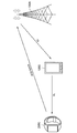
- FIG. 2 is an explanatory diagram for explaining an outline of communication via the relay terminal.
- relay terminal 100C a smart phone etc. which a user holds can be assumed, for example.
- a remote terminal 200C that communicates with the base station 100A via the relay terminal 100C for example, a wearable terminal or the like can be assumed.
- the relay terminal 100C performs, for example, so-called LTE communication (hereinafter also referred to as “backhaul link communication”) with the base station 100A, and performs side link communication with the remote terminal 200C.
- the remote terminal 200C communicates with the base station 100A via the relay terminal 100C.
- the relay terminal 100C can be a communication device that relays communication between the remote terminal 200C and the base station 100A.
- the remote terminal 200C can directly communicate with the base station 100A.
- the remote terminal 200C communicates with the base station 100A via the relay terminal 100C. It becomes important.
- relay communication is realized based on a conventional standard (for example, Enhanced D2D), IP relay is performed, and radio link communication (backhaul link) between the base station 100A and the relay terminal 100C is performed. Communication) and radio link communication (access link communication) between the relay terminal 100C and the remote terminal 200C are managed independently.
- FIG. 3 is an explanatory diagram for explaining an example of a schematic configuration of relay communication.
- An example of relay communication based on a conventional standard is transferred from the base station 100A to the remote terminal 200C via the relay terminal 100C. This is shown focusing on the case where data is transmitted.
- base station 100A performs predetermined transmission processing on data to be transmitted (also referred to as “user data”), performs encoding, modulation, and the like, and then transmits the user data to a relay terminal. Send to 100C.
- predetermined transmission processing on data to be transmitted also referred to as “user data”
- the relay terminal 100 ⁇ / b> C when the relay terminal 100 ⁇ / b> C receives user data from the base station 100 ⁇ / b> A, the relay terminal 100 ⁇ / b> C demodulates and decodes the user data and performs predetermined reproduction processing to acquire the user data. Then, the relay terminal 100C performs predetermined transmission processing on the acquired user data again, performs encoding and modulation, and transmits the user data to the remote terminal 200C. Further, when receiving remote user data from the relay terminal 100C, the remote terminal 200C demodulates and decodes the user data, and obtains the user data by performing a predetermined reproduction process.
- HARQ control is performed only on the backhaul link between the base station 100A and the relay terminal 100C, and on the access link between the relay terminal 100C and the remote terminal 200C. HARQ was not controlled.
- FIG. 4 is an explanatory diagram for describing an overview of relay communication in the system according to an embodiment of the present disclosure.
- the user data is demodulated and decoded in the relay terminal 100 ⁇ / b> C
- the user data is encoded and modulated again.
- Is transmitted to the remote terminal 200C that is, a layer 2 relay is introduced.
- wireless functions for example, retransmission control
- other than modulation, demodulation, encoding, and decoding processes are performed between the base station 100A and the remote terminal 200C. Process transparently.
- an example of a mechanism for guaranteeing communication quality with E2E is based on HARQ (Hybrid Automatic Repeat reQuest).
- HARQ Hybrid Automatic Repeat reQuest
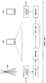
- FIG. 5 is a block diagram illustrating an exemplary configuration of the base station 100 according to an embodiment of the present disclosure.
- the base station 100 includes an antenna unit 110, a wireless communication unit 120, a network communication unit 130, a storage unit 140, and a processing unit 150.
- Antenna unit 110 The antenna unit 110 radiates a signal output from the wireless communication unit 120 to the space as a radio wave. Further, the antenna unit 110 converts radio waves in space into a signal and outputs the signal to the wireless communication unit 120.
- the wireless communication unit 120 transmits and receives signals.
- the radio communication unit 120 transmits a downlink signal to the terminal device and receives an uplink signal from the terminal device.
- the terminal device operates as a relay terminal (the wireless communication device 100C in FIG. 1), and the remote terminal (the terminal device 200C in FIG. 1) and the base station There is a case to relay communication between.
- the wireless communication unit 120 in the wireless communication device 100C corresponding to a relay terminal may transmit / receive a side link signal to / from a remote terminal.
- the network communication unit 130 transmits and receives information.
- the network communication unit 130 transmits information to other nodes and receives information from other nodes.
- the other nodes include other base stations and core network nodes.
- the terminal device may operate as a relay terminal and relay communication between the remote terminal and the base station.
- the wireless communication device 100C corresponding to the relay terminal may not include the network communication unit 130.
- Storage unit 140 The storage unit 140 temporarily or permanently stores a program for operating the base station 100 and various data.
- the processing unit 150 provides various functions of the base station 100.
- the processing unit 150 includes a communication processing unit 151, an information acquisition unit 153, a determination unit 155, and a notification unit 157.
- the processing unit 150 may further include other components other than these components. That is, the processing unit 150 can perform operations other than the operations of these components.
- the operations of the communication processing unit 151, the information acquisition unit 153, the determination unit 155, and the notification unit 157 will be described in detail later.
- FIG. 6 is a block diagram illustrating an exemplary configuration of the terminal device 200 according to an embodiment of the present disclosure.
- the terminal device 200 includes an antenna unit 210, a wireless communication unit 220, a storage unit 230, and a processing unit 240.
- Antenna unit 210 The antenna unit 210 radiates the signal output from the wireless communication unit 220 to the space as a radio wave. Further, the antenna unit 210 converts a radio wave in the space into a signal and outputs the signal to the wireless communication unit 220.
- the wireless communication unit 220 transmits and receives signals.
- the radio communication unit 220 receives a downlink signal from the base station and transmits an uplink signal to the base station.
- the terminal device may operate as a relay terminal and relay communication between the remote terminal and the base station.
- the radio communication unit 220 in the terminal device 200C operating as a remote terminal may transmit / receive a side link signal to / from the relay terminal.
- Storage unit 230 The storage unit 230 temporarily or permanently stores a program for operating the terminal device 200 and various data.
- the processing unit 240 provides various functions of the terminal device 200.
- the processing unit 240 includes a communication processing unit 241, an information acquisition unit 243, a determination unit 245, and a notification unit 247.
- the processing unit 240 may further include other components other than these components. That is, the processing unit 240 can perform operations other than the operations of these components.
- the operations of the communication processing unit 241, the information acquisition unit 243, the determination unit 245, and the notification unit 247 will be described in detail later.
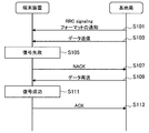
- FIG. 7 is an explanatory diagram for explaining an overview of HARQ, in which the base station 100 transmits data to the terminal apparatus 200, and the terminal apparatus 200 notifies the base station 100 of a data reception result. An example of the case is shown.
- the base station 100 (notification unit 157), based on RRC signaling, uses a control channel (for example, PUCCH (Physical Uplink) for the terminal device 200 to notify the base station 100 of ACK / NACK. Control Channel)) format is notified (S101).
- the base station 100 (communication processing unit 151) transmits data to the terminal device 200 (S103).
- the terminal device 200 When receiving the data transmitted from the base station 100, the terminal device 200 (communication processing unit 241) decodes the received data. Here, it is assumed that the terminal device 200 has failed to decode the data (S105). In this case, the terminal device 200 (notification unit 247) notifies the base station 100 of NACK based on the format notified from the base station 100 based on RRC signaling (S107). That is, the base station 100 (information acquisition unit 153) receives a NACK notification from the terminal device 200 as a response to the transmitted data. Accordingly, the base station 100 (determination unit 155) can recognize that the terminal device 200 has failed to receive data based on the notified NACK.
- the base station 100 (the communication processing unit 151) recognizes that the terminal device 200 has failed to receive data based on the NACK notified from the terminal device 200, the base station 100 (the communication processing unit 151) retransmits the data to the terminal device 200 ( S109).
- the terminal device 200 When receiving the data retransmitted from the base station 100, the terminal device 200 (communication processing unit 241) decodes the received data. Here, it is assumed that the terminal device 200 succeeds in decoding the data (S111). In this case, the terminal device 200 (notification unit 247) notifies the base station 100 of ACK based on the format notified from the base station 100 based on RRC signaling (S113). That is, the base station 100 (information acquisition unit 153) receives an ACK notification from the terminal device 200 as a response to the retransmitted data. Accordingly, the base station 100 (determination unit 155) can recognize that the terminal device 200 has successfully received data based on the notified ACK.
- the terminal device 200 may notify the base station 100 of an ACK in response to the successful decoding of the data transmitted from the base station 100 first. Needless to say, when the data retransmitted from the base station 100 is decoded, the terminal device 200 may notify the base station 100 of NACK again. Further, when notifying ACK or NACK to the base station 100, the terminal device 200 notifies the ACK or NACK based on so-called piggyback using PUSCH (Physical Uplink Shared Channel). Also good.
- PUSCH Physical Uplink Shared Channel
- the base station 100 notifies the terminal device 200 of ACK or NACK using PHICH (Physical HARQ Indicator Channel). do it.
- PHICH Physical HARQ Indicator Channel
- FIG. 8 is an explanatory diagram for explaining an overview of the system according to the present embodiment.
- the base station 100A allocates resources for notifying the reception result of data to both the backhaul link and the uplink, for example. Also good. As another example, the base station 100A may allocate a resource for notifying a data reception result only to the backhaul link, for example. In this case, the relay terminal 100C may execute resource allocation for notifying the data reception result to the access link. Based on such a mechanism, when the relay terminal 100C receives a data reception result (ACK / NACK) from the remote terminal 200C, the relay terminal 100C notifies the base station 100A of the reception result. Thereby, the base station 100A can recognize the reception result of the data transmitted to the remote terminal 200C at the remote terminal 200C.
- ACK / NACK data reception result
- a plurality of remote terminals 200C may be connected to the relay terminal 100C. Therefore, for example, when the number of remote terminals 200C connected to the relay terminal 100C increases, the relay terminal 100C indicates the data reception result (that is, the reception result notified from the remote terminal 200C) at the remote terminal 200C to the base station. More resources may be required to notify 100A.
- the base station 100A determines whether or not the backhaul link is in accordance with information related to the remote terminal 200C connected to the relay terminal 100C (for example, the number of remote terminals 200C). Controls the allocation of resources for notifying data reception results. By such control, for example, even when the number of remote terminals 200C connected to the relay terminal 100C increases, the relay terminal 100C notifies the base station 100A of the data reception result at the remote terminal 200C. It is possible to secure resources for doing so in a more preferable manner.
- the base station 100A, the relay terminal 100C, and the remote terminal 200C notify the data reception result (ACK / NACK) based on HARQ.
- ACK / NACK data reception result
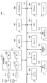
- FIG. 9 is a sequence diagram illustrating an example of a series of processing flow of relay communication in the system according to the present embodiment, and in particular, a processing flow related to resource allocation for notifying ACK and NACK based on HARQ. Shows about.
- the remote terminal 200C and the relay terminal 100C establish communication via a wireless link (ie, access link) in order to transmit and receive data to each other (S201).
- the relay terminal 100C (notification unit 157) transmits information (for example, the number of serving terminals) related to the remote terminal 200C connected to the relay terminal 100C to the base station. 100A is notified (S203a).
- the remote terminal 200C (notifying unit 247) transmits information on the remote terminal 200C via a direct wireless link (hereinafter also referred to as “Uu link”) with the base station 100A. You may notify to a base station (S203b).
- the base station 100A based on the notified information on the remote terminal 200C, notifies the backhaul link with the relay terminal 100C of the data reception result (ACK / NACK) based on HARQ. Assign.
- base station 100A determines unit 155, based on the notified information on remote terminal 200C, receives data reception result (ACK) between base station 100A and relay terminal 100C. / NACK) resource available for notification is determined (S205). Then, the base station 100A (communication processing unit 151) allocates the resource determined based on the information regarding the remote terminal 200C to the backhaul link (S207). At this time, the base station 100A may allocate a resource pool that can be used for ACK and NACK notification to the backhaul link. As another example, base station 100A may schedule resources for performing notification of ACK and NACK, and allocate resources to the backhaul link based on the scheduling result.
- the base station 100A may determine resource blocks (for example, the number of resource blocks) necessary for notification of ACK and NACK based on the notified information on the remote terminal 200C. Details of processing related to the allocation of the resource to the backhaul link by the base station 100A will be described later.
- base station 100A notifies the data reception result (ACK / NACK) based on HARQ to the access link between relay terminal 100C and remote terminal 200C based on the notified information on remote terminal 200C. Resources may be allocated.
- the base station 100A may allocate a resource pool that can be used for notification of a data reception result (ACK / NACK) via the access link (Option 1).
- the base station 100A determines a resource pool that can be used for notification of ACK and NACK based on the notified information about the remote terminal 200C (S209a). Then, the base station 100A (communication processing unit 151) may allocate the resource pool determined based on the information regarding the remote terminal 200C to the access link (S211a).
- the base station 100A schedules a resource block for notifying a reception result (ACK / NACK) of data via the access link, and allocates resources to the access link based on the scheduling result. May be assigned (Option2).
- the base station 100A determines resource blocks (for example, the number of resource blocks) necessary for notification of ACK and NACK based on the notified information on the remote terminal 200C (S209b). Then, base station 100A (communication processing unit 151) may schedule resources for performing ACK and NACK according to the determination result of the resource block, and allocate resources to the access link based on the scheduling result ( S211b).
- the relay terminal 100C instead of the base station 100A may allocate resources available for ACK and NACK notification to the access link.
- the base station 100A transmits / receives data via the backhaul link between the relay terminal 100C and the base station 100A and transmits / receives data via the access link between the relay terminal 100C and the remote terminal 200C. And may be explicitly distinguished. Therefore, in the following description, ACK and NACK notified as a result of data transmission / reception via the backhaul link between the relay terminal 100C and the base station 100A are also referred to as “BL ACK” and “BL NACK”. The ACK and NACK notified as a result of data transmission / reception between the relay terminal 100C and the remote terminal 200C via the access link are also referred to as “AL ACK” and “AL NACK”.
- the remote terminal 200C executes reception processing of the data (S215).
- the remote terminal 200C uses the resource allocated to the access link as a reception result of the data transmitted from the relay terminal 100C, and sends an ACK (ie, ACK) to the relay terminal 100C. , AL ACK) is transmitted (S217).
- the relay terminal 100C uses the resource allocated to the backhaul link to base the data reception result on Transmit to the station 100A (S221). If a resource pool is allocated to the backhaul link at this time, the relay terminal 100C selects a transmission resource from the resource pool based on a predetermined condition (S219), and uses the transmission resource as the data. (S221).
- the data reception result for example, AL ACK
- the relay terminal 100C uses the resource allocated to the backhaul link to base the data reception result on Transmit to the station 100A (S221). If a resource pool is allocated to the backhaul link at this time, the relay terminal 100C selects a transmission resource from the resource pool based on a predetermined condition (S219), and uses the transmission resource as the data. (S221).
- the base station 100A performs blind decoding on the reception result of data transmitted from the relay terminal 100C via the backhaul link, for example, based on information held by the base station 100A at a predetermined timing. An attempt is made to decode the result (S223). Through the control as described above, the data reception result (that is, AL ACK / AL NACK) at the remote terminal 200C is notified to the base station 100A via the relay terminal 100C by E2E.
- the description has been given focusing on DL communication in which data is transmitted from the base station 100A to the remote terminal 200C via the relay terminal 100C, but the data reception result is notified.
- the processing related to resource allocation for the purpose is the same for UL communication. That is, in the UL communication, in the example shown in FIG. 9, the subject and the object may be interchanged in each of data transmission and notification of the reception result (ACK / NACK) of the data.
- the base station 100A allocates resources available for notification of ACK and NACK to the backhaul link based on information on the remote terminal 200C notified from the relay terminal 100C or the remote terminal 200C.
- the timing at which the base station 100A allocates the resource to the backhaul link may be set semi-statically or semi-statically from the network side, for example. The timing may be set dynamically.
- Examples of the information related to the remote terminal 200C include the number of remote terminals 200C connected to the relay terminal 100C (that is, the number of serving terminals), the traffic volume of the remote terminal 200C, and the like. With such a configuration, for example, even in a situation where AL ACK and AL NACK are transmitted from each of the plurality of remote terminals 200C connected to the relay terminal 100C to the base station 100A via the relay terminal 100C, sufficient An amount of resources can be secured.
- the base station 100A may change the format of the control channel (for example, PUCCH) for the relay terminal 100C to notify ACK and NACK based on the notified information on the remote terminal 200C.
- PUCCH control channel
- the base station 100A supports notification of ACK and NACK (that is, AL ACK and AL NACK) from the plurality of remote terminals 200C via the relay terminal 100C
- a format capable of simultaneously reporting ACK and NACK is assigned.
- An example of such a format is “Format 4” defined by 3GPP rules.
- not only the existing format but also a new format may be defined.
- a new format that can change the amount of resources allocated to notify ACK and NACK according to the number of remote terminals 200C connected to the relay terminal 100C is defined. Good.
- one control channel for example, for notifying ACK and NACK to the other
- PSCCH Physical Sidelink Control Channel
- the format assignment from the base station 100A to the relay terminal 100C and the remote terminal 200C may be performed based on, for example, predetermined signaling (for example, RRC signaling).
- predetermined signaling for example, RRC signaling
- the relay terminal 100C receives the AL ACK and AL NACK notification from the remote terminal 200C, and uses the so-called Piggy Back when notifying the base station 100A of the AL ACK and AL NACK. Good.
- relay terminal 100C when relay terminal 100C holds an uplink transmission signal, relay terminal 100C transmits AL ACK or AL NACK notified from remote terminal 200C to PUSCH when transmitting the uplink transmission signal. You can piggyback. Further, as another example, attention is paid to a case where the relay terminal 100C holds an uplink transmission signal and itself notifies the base station 100A of BL ACK or BL NACK.
- the relay terminal 100C when the relay terminal 100C transmits the uplink transmission signal, the relay terminal 100C receives the BL ACK or BL NACK notified to the base station 100A and the AL ACK or AL NACK notified from the remote terminal 200C. You may piggyback to PUSCH.
- the base station 100A allocates a resource pool that can be used for ACK and NACK notification to the backhaul link based on the information about the remote terminal 200C notified from the relay terminal 100C or the remote terminal 200C. At this time, the base station 100A has a sufficient amount of resources for the relay terminal 100C to notify the base station 100A of the ACK and NACK notified from the one or more remote terminals 200C based on the notified information about the remote terminal 200C.
- the resource pool size is determined so that it can be secured.
- the base station 100A may notify at least one of the relay terminal 100C and the remote terminal 200C whether or not to perform feedback transmission using a resource pool that can be used for notification of ACK and NACK.
- the relay terminal 100C or the remote terminal 200C may notify the base station 100A of information related to the remote terminal 200C.
- the base station 100A may assign the resource pool that can be used for notification of ACK and NACK to the relay terminal 100C by semi-statically assigning to the PUSCH or PDSCH. Also, the base station 100A may be assigned so as to satisfy, for example, a HARQ round drip time.
- the base station 100A includes, for example, a period, a period, offset information from a reference point (SFN (System Frame Number), etc.), pool time frequency information, etc.
- the relay terminal 100C may be notified using SIB (System Information Block) or the like.
- the relay terminal 100C selects a resource used for transmission of ACK and NACK (for example, BL ACK, BL NACK, AL ACK, or AL NACK) to the base station 100A from the resource pool allocated by the base station 100A.
- ACK and NACK for example, BL ACK, BL NACK, AL ACK, or AL NACK
- the relay terminal 100C selects a resource for notifying the base station 100A of AL ACK and AL NACK notified from the remote terminal 200C based on a predetermined condition.
- the relay terminal 100C selects information on the remote terminal 200C (for example, terminal identification information, data retransmission count, transmission packet priority information, remote terminal 200C position information, and the like). It may be used as a condition for this.
- the relay terminal 100C may use information for managing the remote terminal 200C in the relay terminal 100C as a condition for selecting the resource.
- Examples of the information for managing the remote terminal 200C in the relay terminal 100C include, for example, identification information of the remote terminal 200C (information given from the relay terminal 100C, the base station 100A, or a higher layer), packet priority Information, terminal priority information, and the like. Note that the relay terminal 100C may use at least a part of the information described above as a condition for selecting the resource.
- a common condition is set between the base station 100A and the relay terminal 100C as a predetermined condition for the relay terminal 100C to select a resource to be used for transmission of ACK and NACK from the resource pool. Therefore, the predetermined condition may be notified from the base station 100A to the relay terminal 100C, for example. With such a configuration, the base station 100A can recognize which of the resources in the resource pool is used for notification of AL ACK and AL NACK from which remote terminal 200C. .
- the relay terminal 100C may multiplex, for example, AL ACK or AL NACK notified from one or more remote terminals 200C and transmit it to the base station 100A.
- relay terminal 100C may notify base station 100A that AL ACK or AL NACK has been multiplexed and information related to remote terminal 200C in which AL ACK or AL NACK has been multiplexed.
- the relay terminal 100C may perform multiplexing for each of various priorities such as packet priority and terminal priority.
- the base station 100A may allocate a resource pool when allocating resources to the access link (Option 1), or may allocate resources based on scheduling results of ACK and NACK notification ( Option2).
- the base station 100A transmits information on setting of resources that can be used for notification of ACK and NACK assigned to the access link to at least one of the relay terminal 100C and the remote terminal 200C at a predetermined timing. Notification may be made in advance. Note that the timing at which the base station 100A performs the notification may be set to be semi-static from the network side, or may be fixedly set. The timing may be set dynamically.
- the base station 100A determines that the resource pool information (eg, period, period, offset information from a reference point (SFN, etc.), pool time, etc. Frequency information, etc.) may be notified to at least one of the relay terminal 100C and the remote terminal 200C using SIB or the like.
- the base station 100A may notify the remote terminal 200C directly via the Uu link or via the relay terminal 100C. Notification may be made indirectly by relay communication.
- a resource pool is allocated to an access link (Option 1)
- communication via the access link may be encoded based on a predetermined encoding method.
- different orthogonal codes may be assigned to each relay terminal 100C or each remote terminal 200C, and other non-orthogonal multiplexing schemes may be used.
- the remote terminal 200C randomly selects a resource for notifying the relay terminal 100C of ACK and NACK from the resource pool at a predetermined timing. May be.
- the timing at which the remote terminal 200C selects a resource from the resource pool may be set semi-statically or semi-statically from the network side, for example. The timing may be set dynamically.
- the remote terminal 200C may select a resource for notifying the relay terminal 100C of ACK and NACK from the resource pool based on a predetermined condition.
- the remote terminal 200C has its own terminal identification information, the number of times of data retransmission, the priority information of the transmission packet, its own position information, and its own terminal identification information (relay terminal 100C managed on the relay terminal 100C side).
- the resource may be selected from the resource pool using at least part of the information (information given from the base station 100A or a higher layer).
- the remote terminal 200C may use resources instructed from the base station 100A or the relay terminal 100C.
- the remote terminal 200C selects a resource to be used for the notification from the resource pool focusing on the case where the remote terminal 200C notifies the relay terminal 100C of ACK and NACK. did.
- the relay terminal 100C selects a resource from the resource pool in the same manner as described above. Also good.
- the base station 100A may notify information regarding the scheduled resource block (for example, resource block position information) to at least one of the relay terminal 100C and the remote terminal 200C.
- the base station 100A may directly notify the remote terminal 200C via the Uu link, or via the relay terminal 100C. Notification may be made indirectly by relay communication.
- the timing at which the base station 100A allocates the resource pool may be set semi-statically or semi-statically from the network side, for example.
- the timing may be set dynamically.
- the base station 100A when the base station 100A does not use a resource (ie, SPS (Semi Persistent Scheduling) resource) allocated in a semi-static manner in advance (that is, when it is not activated), the base station 100A allocates the resource. It may be used for other purposes.
- a resource ie, SPS (Semi Persistent Scheduling) resource
- the base station 100A determines the data reception result (ACK / NACK) for the backhaul link according to the information about the remote terminal 200C connected to the relay terminal 100C. ) Control resource allocation for notification. In addition, base station 100A may control allocation of resources for notifying a data reception result (ACK / NACK) to an access link according to information related to remote terminal 200C.
- Second Embodiment >> ⁇ 4.1. Overview> Subsequently, as a second embodiment, an example of a mechanism for realizing data retransmission control based on HARQ in relay communication via the relay terminal 100C between the base station 100A and the remote terminal 200C will be described.
- FIG. 10 is an explanatory diagram for explaining an overview of the system according to the present embodiment.
- the relay terminal 100C between the base station 100A and the remote terminal 200C, between the base station 100A and the relay terminal 100C (that is, the backhaul link), between the relay terminal 100C and the remote terminal 200C.
- Data transmission / reception is performed during each period (ie, access link). Therefore, for example, when data is transmitted from the base station 100A to the remote terminal 200C via the relay terminal 100C, even if the data transmission via the backhaul link is successful, the data transmission via the access link is performed. May fail.
- resources allocated to access links are often more limited than resources allocated to backhaul links. For this reason, communication via the access link may be likely to be a resource shortage compared to communication via the backhaul link.
- the base station 100A fails to perform the failure. May be difficult to recognize. Therefore, in relay communication via the relay terminal 100C between the base station 100A and the remote terminal 200C, it may be difficult to guarantee the link quality with E2E.
- FIG. 11 is a flowchart illustrating an example of a flow of a series of processes of the system according to the present embodiment.
- the relay terminal 100C relay-transmits data transmitted from the base station 100A to the remote terminal 200C (hereinafter referred to as “DL communication”). (It will also be called).
- the base station 100A controls communication related to data transmission to the remote terminal 200C based on the fed back information (S307). For example, the base station 100A changes various settings related to communication between the relay terminal 100C and the remote terminal 200C via the access link based on the fed back information, and is at least one of the relay terminal 100C and the remote terminal 200C. You may instruct. Further, the base station 100A may control resource allocation to the access link. The base station 100A may instruct at least one of the relay terminal 100C and the remote terminal 200C to switch the radio link used for data transmission (retransmission) based on the fed back information.
- base station 100A may instruct relay terminal 100C to retransmit data. Further, as another example, when the relay terminal 100C receives an instruction or the like related to the change of the setting from the base station 100A, the data retransmission may be performed.
- the remote terminal 200C succeeds in decoding the data and transmits AL NACK directly or indirectly to the base station 100A.
- the base station 100A (information acquisition unit 153) receives the AL ACK from the remote terminal 200C (S303, YES), and ends a series of processes related to the transmission of the data.
- the system according to the present embodiment realizes retransmission control in a more preferable manner in relay communication via the relay terminal 100C between the base station 100A and the remote terminal 200C, and eventually by E2E. It is possible to guarantee the link quality.
- retransmission control based on HARQ is realized in relay communication via the relay terminal 100C between the base station 100A and the remote terminal 200C.
- An example of a mechanism for doing this has been described.
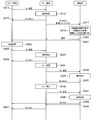
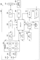
- FIG. 12 is a sequence diagram illustrating an example of a series of processing flow of relay communication in the system according to the present embodiment, and illustrates an example of retransmission control in DL communication.
- the base station 100A (communication processing unit 151) transmits data to the relay terminal 100C via the backhaul link (S311), and the relay terminal 100C (communication processing unit 151) Assume that decoding of the data has failed (S313).
- the relay terminal 100C (notification unit 157) notifies BL NACK to the base station 100A (S315).
- the base station 100A executes the data retransmission processing (S317, S319).
- the relay terminal 100C succeeds in decoding the data retransmitted from the base station 100A (S321).
- the relay terminal 100C (notification unit 157) notifies the base station 100A of BL ACK (S323).
- the base station 100A can recognize that the retransmission of data to the relay terminal 100C via the backhaul link has succeeded.
- the relay terminal 100C (communication processing unit 151) relays the data received from the base station 100A via the access link to the remote terminal 200C that is the transmission destination of the data (S325, S327).
- the remote terminal 200C has failed to decode the data transmitted from the relay terminal 100C (S329).
- the remote terminal 200C (notifying unit 247) notifies the base station 100A and the relay terminal 100C of AL NACK, and also provides information on the reception result of the data transmitted from the relay terminal 100C. Feedback to 100A.
- the remote terminal 200C may perform AL NACK notification and feedback of the information based on indirect communication (ie, relay communication) via the relay terminal 100C to the base station 100A. Good (S331, S333).
- the remote terminal 200C may perform notification of AL NACK and feedback of the above information based on direct communication via the Uu link to the base station 100A (S335).
- the feedback notification method is not particularly limited as long as the feedback of information related to the reception result of the data transmitted from the relay terminal 100C is associated with the AL NACK notification from the remote terminal 200C.
- the base station 100A Upon receiving the AL NACK notification and the feedback of the information related to the data reception result from the remote terminal 200C, the base station 100A (communication processing unit 151) receives direct or indirect communication with the remote terminal 200C. Control of communication (in other words, E2E communication with the remote terminal 200C) is executed (S337, S339).
- the base station 100A changes various settings related to communication between the relay terminal 100C and the remote terminal 200C via the access link based on the fed back information. You may instruct
- the base station 100A also instructs at least one of the relay terminal 100C and the remote terminal 200C to switch the radio link used for data transmission (retransmission) based on the fed back information. May be.
- the base station 100A is configured such that the relay terminal 100C used for relay communication with the remote terminal 200C is handed over to the other relay terminal 100C. An instruction may be given to at least one of them.
- the base station 100A switches the communication with the remote terminal 200C from the communication through the relay terminal 100C to the direct communication through the Uu link (falls back). You may give instructions to them. Further, the base station 100A may control resource allocation to the access link.
- the relay terminal 100C (communication processing unit 151) executes retransmission processing of the data via the access link with respect to the remote terminal 200C (S341, S343).
- the remote terminal 200C succeeds in decoding the data retransmitted from the relay terminal 100C (S345).
- remote terminal 200C (notification unit 247) notifies AL ACK to base station 100A and relay terminal 100C.
- the remote terminal 200C may notify the base station 100A of AL ACK based on indirect communication (that is, relay communication) via the relay terminal 100C (S347, S349).
- the remote terminal 200C may notify the base station 100A of AL NACK based on direct communication via the Uu link (S351).
- the base station 100A can recognize that the relay transmission of data from the relay terminal 100C to the remote terminal 200C via the access link is successful.
- FIG. 13 is a sequence diagram illustrating another example of a series of processing flow of relay communication in the system according to the present embodiment, and illustrates an example of retransmission control in UL communication.
- the remote terminal 200C (communication processing unit 241) transmits data to the relay terminal 100C via the access link (S411), and the relay terminal 100C (communication processing unit 151) It is assumed that decoding of the data has failed (S413).
- the relay terminal 100C (notification unit 157) notifies the remote terminal 200C of AL NACK (S415). That is, the remote terminal 200C (information acquisition unit 243) receives a notification of AL NACK from the relay terminal 100C as a response to the transmitted data.
- relay terminal 100C (notification unit 157) performs notification of AL NACK from remote terminal 200C and feedback of information related to the reception result of data transmitted from remote terminal 200C to base station 100A ( S417).
- the feedback notification method is not particularly limited.
- the base station 100A (communication processing unit 151) receives the AL NACK notification and the feedback of the information related to the data reception result from the relay terminal 100C
- the base station 100A (communication processing unit 151) directly or indirectly between the corresponding remote terminal 200C Control (in other words, E2E communication with the remote terminal 200C) is executed (S419, S421).
- E2E communication with the remote terminal 200C is executed (S419, S421).
- the details of the control are the same as in the case of the DL communication described above, and thus detailed description thereof is omitted.
- the remote terminal 200C executes retransmission processing of the data via the access link for the relay terminal 100C (S423, S425).
- the relay terminal 100C succeeds in decoding the data retransmitted from the remote terminal 200C (S427).
- relay terminal 100C notification unit 157) notifies AL ACK to remote terminal 200C (S429). That is, the remote terminal 200C (information acquisition unit 243) receives an AL ACK notification from the relay terminal 100C as a response to the retransmitted data.
- the remote terminal 200C determination unit 245) can recognize that the data transmission to the relay terminal 100C via the access link is successful.
- the relay terminal 100C (communication processing unit 151) relays the data received from the remote terminal 200C to the base station 100A via the backhaul link (S431, S433).
- the base station 100A has failed to decode the data transmitted from the relay terminal 100C (S435).
- the base station 100A (notification unit 157) notifies BL NACK to the relay terminal 100C (S437).
- the relay terminal 100C When the relay terminal 100C receives a BL NACK from the base station 100A as a result of data transmission to the base station 100A, the relay terminal 100C executes retransmission processing of the data (S439, S441).
- the base station 100A succeeds in decoding the data retransmitted from the relay terminal 100C (S443).
- base station 100A (notification unit 157) notifies BL ACK to relay terminal 100C and remote terminal 200C.
- the base station 100A may notify the BL ACK to the remote terminal 200C based on indirect communication (ie, relay communication) via the relay terminal 100C (S445, S447).
- the base station 100A may notify the BL ACK to the remote terminal 200C based on direct communication via the Uu link (S449). That is, the remote terminal 200C (information acquisition unit 243) receives a BL ACK notification from the base station 100A as a reception result of the transmitted data based on direct or indirect communication. Thereby, the remote terminal 200C (determination unit 245) can recognize that the relay transmission of data from the relay terminal 100C to the base station 100A via the backhaul link has been successful.
- the data transmission / reception result (BL ACK and BL NACK) via the backhaul link and the data transmission / reception result (AL ACK and AL NACK) is explicitly distinguished. At least a part of BL ACK and BL NACK transmitted / received between relay terminal 100C and base station 100A, and AL ACK and AL NACK transmitted / received between relay terminal 100C and each remote terminal 200C.
- the plurality of pieces of information may be multiplexed and transmitted.
- Example of feedback method The remote terminal 200C feeds back information to the base station 100A as a method of performing feedback indirectly through relay communication via the relay terminal 100C, or directly via a Uu link. And a method of providing feedback.
- the information feedback via the access link between the remote terminal 200C and the relay terminal 100C includes PSCCH or PSSCH ( Physical (Sidelink Shared Channel) can be used.
- PSCCH or PSSCH Physical (Sidelink Shared Channel) can be used.
- PUCCH or PUSCH can be used for feedback of information via the backhaul link between the relay terminal 100C and the base station 100A.
- PDCCH or PDSCH may be used for feedback of information via a backhaul link between relay terminal 100C and base station 100A.
- PUCCH or PUSCH can be used for the feedback.
- PDCCH or PDSCH may be used for the feedback via the Uu link.
- feedback from the remote terminal 200C or the relay terminal 100C to the base station 100A may be executed using a determination result based on a predetermined condition as a trigger.
- a condition that triggers feedback (for example, a threshold for determination) may be set to be semi-static from the base station 100A or a higher layer, for example, and fixedly. It may be set. Further, the condition may be set dynamically.
- the conditions that trigger the feedback include, for example, the number of times data transmission through the access link has failed, information on the communication quality of the access link (for example, the result of RRM measurement for the access link (side link)), and the like. Can be mentioned.
- information related to the resource pool for example, the use status of resources in the resource pool (congestion status)
- a sensing result of resource usage in a predetermined resource pool or a predetermined frequency band may be used as a condition that triggers feedback.
- the remote terminal 200C may perform feedback to the base station 100A or the relay terminal 100C when the various information exceeds a threshold value.
- 100 C of relay terminals may perform feedback with respect to 100 A of base stations, when the various information mentioned above exceeds a threshold value.
- the relay terminal 100C determines a condition that triggers feedback for the base station 100A
- the number of remote terminals 200C that have fed back to the relay terminal 100C may be used as the condition. Good.
- the relay terminal 100C may perform feedback to the base station 100A when the number of remote terminals 200C that have performed feedback to the relay terminal 100C exceeds a threshold.
- a period for collecting information used for determining whether to perform feedback may be set.
- the remote terminal 200C or the relay terminal 100C may perform feedback of information to the base station 100A when a condition that triggers feedback is satisfied during the window period.
- the base station 100A may set the start (End) and end (Duration) of the window period for the remote terminal 200C or the relay terminal 100C.
- the remote terminal 200C or the relay terminal 100C may clear the counter of information that has been counted during the window period.
- FIG. 14 is an explanatory diagram for explaining an aspect of the operation of the system according to the present embodiment, and shows an outline of the operation of the base station 100A that has received feedback from the remote terminal 200C.
- the relay terminal 100C relay-transmits data transmitted from the base station 100A to the relay terminal 100C
- the resource of the access link is insufficient, and the relay transmission is not performed.
- the remote terminal 200C notifies the base station 100A directly or indirectly that the transmission of the data has failed.
- the base station 100A receives feedback of information related to transmission / reception of the data via the access link from the remote terminal 200C or the relay terminal 100C, and executes a countermeasure corresponding to the feedback. Therefore, an example of countermeasures executed by the base station 100A according to feedback will be described below.
- (3-1) Data Retransmission Instruction When the base station 100A receives feedback from the remote terminal 200C or the relay terminal 100C, the base station 100A determines whether to transmit the data of the remote terminal 200C or the relay terminal 100C according to the feedback. The transmission source may be instructed to retransmit data.
- Transmission mode control when data is retransmitted, a communication mode (that is, transmission mode) in data retransmission via the access link between the remote terminal 200C and the relay terminal 100C may be controlled.
- the base station 100A selects any one of the following modes 1 to 3 and switches to the selected mode based on a predetermined indicator (for example, Mode Indicator). And at least one of the relay terminals 100C.
- mode 1 is a mode in which base station 100A schedules a resource block to be used for data transmission via an access link, and instructs the resource block to remote terminal 200C or relay terminal 100C.
- mode 2 is a mode in which the remote terminal 200C or the relay terminal 100C itself selects a resource to be used for data transmission from a resource pool that can be used for data transmission via the access link.
- the resource pool may be set by the base station 100A, or may be set in advance (may be pre-configured).
- Mode 3 is used for data transmission via the access link from the resource pool (hereinafter also referred to as “relay resource pool”) that can be used by the relay terminal 100C for data transmission via the access link.
- the relay resource pool may be set by the base station 100A, or may be set in advance (may be pre-configured).
- Resource pool control In addition, when data is retransmitted, the setting of a resource pool that can be used for data transmission via an access link may be controlled.
- the base station 100A may reset the resource pool so that the size of the resource pool becomes larger when there are not enough resources available for data transmission / reception via the access link. Additional allocations may be made.
- the base station 100A may change a resource pool that has already been set as another resource pool as a resource pool that can be used for data transmission via the access link.
- the base station 100A may apply the frequency hopping setting for the use of the resource pool.
- the base station 100A may provide information related to frequency hopping settings to the remote terminal 200C or the relay terminal 100C.
- the base station 100A may notify the remote terminal 200C or the relay terminal 100C of information regarding the resource pool after the setting change.
- information regarding the resource pool notified at this time for example, information regarding the frequency domain and information regarding the time domain may be cited.
- Examples of information on the frequency domain include PRB (Physical Resource Block) start position (PRB Start), PRB end position (PRB End), the number of PRBs, and subchannel information.
- examples of information related to the time domain include a bitmap indicator, a subframe number, and a frame number.
- the base station 100A may notify the remote terminal 200C or the relay terminal 100C of the resource pool hopping flag. Further, base station 100A may instruct remote terminal 200C or relay terminal 100C with a hopping pattern using a resource pool popping indicator.
- Parameters related to data transmission via the access link include, for example, transport block size (Transport Block Size), modulation method (Modulation Scheme), resource block allocation (Allocated Resource Blocks), and data block to be retransmitted. For example, an iterative version (Redundancy Version) representing a feature.
- Transport Block Size Transport Block Size
- Modulation Scheme Modulation Scheme
- Resource Block allocation Allocated Resource Blocks
- Data block to be retransmitted For example, an iterative version (Redundancy Version) representing a feature.
- an iterative version representing a feature.
- These parameters may be directly assigned and controlled by limiting the parameter selection range. In the case of control for limiting the parameter selection range, the parameter selection range may be controlled by defining several modes and assigning specific modes.
- the base station 100A may directly notify the remote terminal 200C of information related to the above setting using DCI (Downlink Control Information) or SIB (System Information Block).
- the base station 100A may indirectly notify the remote terminal 200C of information regarding the setting via the relay terminal 100C.
- the notification of the information from the base station 100A to the relay terminal 100C may be performed using DCI or SIB, for example.
- the notification of the information from the relay terminal 100C to the remote terminal 200C may be performed using, for example, SCI (Sidelink Control Information).
- the above setting at the time of data retransmission may be selected by the terminal itself that is the data transmission source among the remote terminal 200C and the relay terminal 100C.
- the setting range that the remote terminal 200C and the relay terminal 100C select when retransmitting data may be instructed from the base station 100A or the network side, for example.
- DCI or SIB can be used.
- the relay terminal 100C may notify the remote terminal 200C of information regarding the setting using the SCI.
- the base station 100A may switch the relay terminal 100C used for relay communication with the remote terminal 200C to another relay terminal 100C (that is, handover or reselection). .
- the base station 100A may notify the relay terminal 100C as a switching destination of the switching request (that is, a handover request or a reselection request). That is, the relay terminal 100C as the switching destination may start various processes related to handover or reselection in response to the request from the base station 100A.
- the base station 100A may notify a handover request or reselection request message to a candidate for the relay terminal 100C located in the vicinity.
- the base station 100A may notify the candidate of the relay terminal 100C located nearby by using a discovery signal, for example, a handover request message or a reselection request message.
- the base station 100A may notify the remote terminal 200C of a request for switching the relay terminal 100C (that is, a handover request or a reselection request). In this case, for example, the base station 100A may notify the remote terminal 200C of the switching request directly via the Uu link. As another example, the base station 100A may indirectly notify the switching request to the remote terminal 200C via the relay terminal 100C. In addition, the remote terminal 200C may start various processes related to handover or reselection in response to the request from the base station 100A.
- the base station 100A may switch communication with the remote terminal 200C from relay communication via the relay terminal 100C to direct communication via the Uu link.
- the base station 100A uses the relay terminal 100C used for relay communication based on a so-called CoMP (Coordinated Multi-Point) technique.
- CoMP Coordinatd Multi-Point
- the base station 100A newly sets a relay terminal 100C used for CoMP transmission. Then, the base station 100A transmits data to the remote terminal 200C via the plurality of relay terminals 100C by CoMP transmission using the plurality of relay terminals 100C including the newly set relay terminal 100C. At this time, the base station 100A applies the CoMP transmission to the relay communication via the relay terminal 100C between the base station 100A and the remote terminal 200C, and the plurality of relay terminals 100C used for CoMP transmission. To instruct.
- a CoMP transmission method for example, a method such as Joint Transmission that simultaneously transmits the same data from a plurality of relay terminals 100C, or Dynamic Relay selection that instantaneously switches a transmission link is used.
- the base station 100A may instruct each of the plurality of relay terminals 100C used for CoMP transmission to transmit different RVs (Redundancy Versions).
- the base station 100A or the remote terminal 200C may instruct information related to resources used for CoMP transmission to each of the plurality of relay terminals 100C used for CoMP transmission.
- the base station 100A feeds back information related to data transmission / reception via the access link in relay communication with the remote terminal 200C via the relay terminal 100C. Is received from at least one of the remote terminal 200C and the relay terminal 100C.
- the base station 100A receives the feedback of the information related to the transmission / reception of the data, and then performs direct or indirect communication with the remote terminal 200C corresponding to the information (in other words, E2E with the remote terminal 200C). Control).
- the system according to the present embodiment realizes retransmission control in a more preferable manner in relay communication via the relay terminal 100C between the base station 100A and the remote terminal 200C, and eventually by E2E. It is possible to guarantee the link quality.
- radio access methods between communication via the access link from the relay terminal 100C to the remote terminal 200C and communication via the Uu link from the base station 100A to the remote terminal 200C (DL communication). May be used.
- a single carrier radio access method called SC-FDMA (Single Carrier-Frequency Division Multiple Access) is used. Is done.
- SC-FDMA Single Carrier-Frequency Division Multiple Access
- OFDMA Orthogonal frequency-division multiple access
- some terminal devices that operate as the remote terminal 200C require low power consumption.
- a receiver corresponding to each of a plurality of wireless access methods is provided for the terminal device, power consumption tends to be higher.
- Some terminal devices operating as the remote terminal 200C are required to be low in cost, such as so-called low cost terminals. Therefore, it may be assumed that only the receiver corresponding to any of the wireless access methods as described above is provided as the remote terminal 200C. From such a situation, it may be assumed that so-called unidirectional communication is applied in relay communication via the relay terminal 100C between the base station 100A and the remote terminal 200C.
- FIG.15 and FIG.16 is explanatory drawing for demonstrating the outline
- the example illustrated in FIG. 16 illustrates an example of a configuration of unidirectional communication in a case where the remote terminal 200C includes only a receiver that supports SC-FDMA as a wireless communication receiver.
- the remote terminal 200C can receive data transmitted from the relay terminal 100C based on the SC-FDMA scheme, but cannot receive data transmitted from the base station 100A based on the OFDMA scheme. Have difficulty. Therefore, the remote terminal 200C receives data transmitted from the base station 100A based on relay communication via the relay terminal 100C.
- the remote terminal 200C determines that the reception result (ACK / NACK) of the data received from the base station 100A via the relay terminal 100C is based on communication with the base station 100A via the Uu link. Directly notify the station 100A.
- the base station 100A and the remote terminal 200C HARQ control can be realized in relay communication via the relay terminal 100C.
- the remote terminal 200C fails to decode data received from the base station 100A in the example shown in FIG.
- the process related to the retransmission of the data is executed by the base station 100A after the NACK transmitted from the remote terminal 200C is received by the base station 100A via the relay terminal 100C.
- the remote terminal 200C fails to decode data received from the base station 100A in the example shown in FIG.
- the remote terminal 200C can notify the NACK directly to the base station 100A.
- retransmission of data from the base station 100A to the remote terminal 200C is performed again by relay communication via the relay terminal 100C. That is, the data retransmitted by the base station 100A is received by the relay terminal 100C, and the relay terminal 100C relays the data to the remote terminal 200C.
- the relay terminal 100C when the remote terminal 200C fails to decode the data transmitted from the base station 100A, the relay terminal 100C replaces the retransmission of the data with the base station 100A. Do on behalf.
- the fact that the relay terminal 100C resends data on behalf is also referred to as “proxy transmission”.
- data is retransmitted from the relay terminal 100C to the remote terminal 200C without directly or indirectly retransmitting data from the base station 100A to the remote terminal 200C.
- the remote terminal 200C receives data directly from the base station 100A via the Uu link (see FIG. 15) and indirectly receives data via the relay terminal 100C (see FIG. 15). (See FIG. 16).
- FIG. 17 is a sequence diagram illustrating an example of a flow of a series of processes of the system according to the present embodiment.
- the base station 100A sets the relay terminal 100C used for proxy transmission at the time of retransmission control in relay communication with the remote terminal 200C via the relay terminal 100C (S501).
- the base station 100A (notification unit 157) may notify the relay terminal 100C selected to be used for proxy transmission that it will be used for proxy transmission at the time of retransmission control. You may notify the setting regarding transmission, etc.
- the base station 100A transmits data (DL signal) to the remote terminal 200C via the Uu link (S503).
- the base station 100A (communication processing unit 151) transmits the data transmitted to the remote terminal 200C via the backhaul link to the relay terminal 100C used for proxy transmission at the time of retransmission control (S505).
- the remote terminal 200C fails to decode the data transmitted from the base station 100A (S507), and the relay terminal 100C succeeds in decoding the data transmitted from the base station 100A (S509).
- the relay terminal 100C (notification unit 157) succeeds in decoding the data (DL signal) transmitted from the base station 100A (S509)
- the relay terminal 100C (notification unit 157) may transmit an ACK to the base station 100A (S511).
- the remote terminal 200C When the remote terminal 200C fails to decode the data transmitted from the base station 100A (S507), the remote terminal 200C transmits a NACK to the relay terminal 100C via the access link (S513).
- the relay terminal 100C (communication processing unit 151) retransmits the data (DL signal) received from the base station 100A in advance to the remote terminal 200C as a proxy for the base station 100A. (S515, S517). At this time, the relay terminal 100C retransmits data to the remote terminal 200C based on the same radio access scheme (for example, OFDMA) as when the base station 100A transmits data to the remote terminal 200C.
- OFDMA radio access scheme
- the relay terminal 100C (notification unit 157) retransmits data to the remote terminal 200C as a proxy of the base station 100A
- the relay terminal 100C notifies the base station 100A that the data has been retransmitted by proxy ( S519).
- the base station 100A can recognize that it is not necessary to execute a process related to retransmission of data to the remote terminal 200C.
- the remote terminal 200C succeeds in decoding the data retransmitted from the relay terminal 100C on behalf of the base station 100A (S521).
- the remote terminal 200C (notification unit 247) notifies the relay terminal 100C of ACK (S523).
- the relay terminal 100C (notifying unit 157) relays the notified ACK to the base station 100A (S525).
- the base station 100A (determination unit 155) can recognize that the data (DL signal) transmitted to the remote terminal 200C has been correctly received by the remote terminal 200C.
- the base station 100A sets the relay terminal 100C used for proxy transmission at the time of retransmission control in relay communication with the remote terminal 200C via the relay terminal 100C (S551).
- the base station 100A (notification unit 157) may notify the relay terminal 100C selected to be used for proxy transmission that it will be used for proxy transmission at the time of retransmission control. You may notify the setting regarding transmission, etc.
- the base station 100A (communication processing unit 151) transmits data (DL signal) to be transmitted to the remote terminal 200C to the relay terminal 100C to which the remote terminal 200C is connected via the backhaul link (S553).
- the relay terminal 100C succeeds in decoding the data (S555).
- the relay terminal 100C (notification unit 157) notifies the base station 100 of ACK (S557). Accordingly, the base station 100 (determination unit 155) can recognize that the relay terminal 100C has successfully received data based on the notified ACK.
- the relay terminal 100C (communication processing unit 151) relays the data (DL signal) received from the base station 100A to the remote terminal 200C that is the transmission destination of the data via the access link (S559). ).
- the remote terminal 200C has failed to decode the data (S661).
- the remote terminal 200C (notification unit 247) notifies NACK to the base station 100A based on direct communication via the Uu link (S563).
- the relay terminal 100C decodes NACK transmitted directly from the remote terminal 200C to the base station 100A by blind-decoding data transmitted from the remote terminal 200C (S565).
- the relay terminal 100C (determination unit 155) can recognize that the remote terminal 200C has failed to receive data.
- the base station 100A may notify the relay terminal 100C in advance of information on the resource to which the NACK signal is transmitted at this time.
- a notification of NACK by the remote terminal 200C may be notified to the relay terminal 100C via the base station 100A.
- the base station 100A transfers the notified NACK to the relay terminal 100C instead of retransmitting the data that the remote terminal 200C has failed to decode. May be.
- the relay terminal 100C (determination unit 155) can recognize that the remote terminal 200C has failed to receive data.
- the relay terminal 100C When the relay terminal 100C recognizes that the remote terminal 200C has failed to receive data, the relay terminal 100C executes processing related to retransmission of the data to the remote terminal 200C. At this time, the relay terminal 100C (notification unit 157) first sends it to the base station 100A. Notification of resending data on behalf is sent (S567). Thereby, it becomes possible for base station 100A to recognize that it is not necessary to execute processing related to retransmission of data via relay terminal 100C to remote terminal 200C. In addition, the relay terminal 100C (communication processing unit 151) retransmits data that the remote terminal 200C has failed to receive, that is, data (DL signal) previously received from the base station 100A to the remote terminal 200C (S571).
- data DL signal
- the remote terminal 200C succeeds in decoding the data retransmitted from the relay terminal 100C (S571).
- the remote terminal 200C (notification unit 247) notifies the base station 100A of ACK based on direct communication via the Uu link (S575).
- the base station 100A (determination unit 155) can recognize that the remote terminal 200C has successfully received data.
- the relay terminal 100C decodes the ACK transmitted directly from the remote terminal 200C to the base station 100A by blind decoding the data transmitted from the remote terminal 200C (S577).
- the relay terminal 100C determination unit 155) can recognize that the remote terminal 200C has successfully received data.
- the base station 100A sets the relay terminal 100C used for proxy transmission at the time of retransmission control in relay communication with the remote terminal 200C via the relay terminal 100C at a predetermined timing.
- the base station 100A may notify the relay terminal 100C selected to be used for proxy transmission that it is used for proxy transmission at the time of retransmission control. You may notify the setting etc. regarding.
- the base station 100A may perform the notification to the relay terminal 100C using RRC signaling, for example. Further, the base station 100A may use, for example, a request message or a reply message for the notification to the relay terminal 100C.
- the base station 100A may set the relay terminal 100C used for proxy transmission at the time of retransmission control in accordance with information related to the capability of each relay terminal 100C.
- the information regarding the capability of the relay terminal 100C include the memory capacity, battery information, terminal category (Category), and RF configuration of the relay terminal 100C.
- the relay terminal 100C used for proxy transmission at the time of retransmission control may be set by a higher layer (Higher Layer) than the base station 100A.
- the timing at which the base station 100A sets the relay terminal 100C used for proxy transmission at the time of retransmission control may be set to semi-static (Semi persistent) from the network side, for example, or may be fixedly set. Also good. The timing may be set dynamically.
- the relay terminal 100C for which proxy transmission has been set receives the data transmitted from the base station 100A to the remote terminal 200C via the Uu link in the same manner and decodes the data.
- the remote terminal 200C uses information (for example, blind decoding) to be used to decode the data transmitted from the base station 100A to the relay terminal 200C via the Uu link (for example, blind decoding).
- the RNTI information may be notified to the relay terminal 100C in advance.
- the base station 100A may notify the relay terminal 100C of information used for decoding the data using DCI.
- the base station 100A controls transmission of the data so that both the remote terminal 200C and the relay terminal 100C can decode the data (DL signal) transmitted to the remote terminal 200C.
- the base station 100A may notify the data area used for transmission of the data using the common DCI to both the remote terminal 200C and the relay terminal 100C.
- the base station 100A may set an area used for the notification of the common DCI in advance.
- the base station 100A may assign different DCIs to the remote terminal 200C and the relay terminal 100C, respectively.
- the base station 100A may indicate a common data area (that is, a data area used for data transmission) by DCI assigned to each of the remote terminal 200C and the relay terminal 100C.
- the base station 100A may individually transmit common data (DL signals) to the remote terminal 200C and the relay terminal 100C using different resources.
- the base station 100A individually sets the data area used for transmission of the data and the DCI for notifying the data area between the remote terminal 200C and the relay terminal 100C, respectively. May be individually notified.
- the base station 100A may add and transmit information related to the remote terminal 200C as a data transmission destination to the DCI assigned to the relay terminal 100C.
- the relay terminal 100C may perform the paging setting of the remote terminal 200C for itself and receive a paging signal in accordance with the paging timing of the remote terminal 200C. That is, the base station 100A may set the paging timing of the remote terminal 200C for the relay terminal 100C.
- the relay terminal 100C for which proxy transmission is set performs decoding (for example, blind decoding) of ACK and NACK transmitted from the remote terminal 200C to the base station 100A via the Uu link. Therefore, for example, the base station 100A transmits information on the resources of the ACK and NACK so that the relay terminal 100C can decode (blind decode) the ACK and NACK transmitted from the remote terminal 200C via the Uu link. The relay terminal 100C may be notified in advance.
- the remote terminal 200C relays information (for example, RNTI information) used for decoding the ACK and NACK so that the relay terminal 100C can decode ACK and NACK transmitted to the base station 100A via the Uu link. The terminal 100C may be notified in advance.
- the base station 100A may notify the relay terminal 100C of information used for decoding the ACK and NACK using DCI.
- the relay terminal 100C may assign a PSCCH format to the remote terminal 200C in order to grasp the ACK and NACK resources used in the remote terminal 200C.
- the relay terminal 100C uses the PSCCH format assigned to the remote terminal 200C to grasp the resources used by the relay terminal 100C for notification of ACK and NACK to the base station 100A, and uses the ACK and NACK. What is necessary is just to decode.
- data (DL signal) transmitted from the base station 100A to the remote terminal 200C is also transmitted to the relay terminal 100C in the same manner.
- the relay terminal 100C notifies the base station 100A that the retransmission of the data is performed by proxy using a predetermined method.
- the relay terminal 100C when the relay terminal 100C succeeds in decoding the data transmitted from the base station 100A, the relay terminal 100C notifies the base station 100A of ACK, thereby resending the data on behalf May be notified to the base station 100A. That is, when ACK is notified as a response to data transmission to the relay terminal 100C, the base station 100A determines that the above-described proxy transmission control is performed by the relay terminal 100C for the target transport block. Is possible. Therefore, for example, when the ACK is notified from the relay terminal 100C, the base station 100A determines whether a response (ACK / NACK) to the data transmitted to the remote terminal 200C is returned within a predetermined time. A timer for judging the above may be stopped.
- the relay terminal 100C may explicitly notify the base station 100A that data retransmission is performed on behalf.
- the notification corresponds to, for example, the notification indicated by reference numeral S519 in the example shown in FIG. 17 and the notification indicated by reference numeral S567 in the example shown in FIG.
- the base station 100A can determine that the above-described proxy transmission control is performed by the relay terminal 100C serving as the notification source for the target transport block. Therefore, for example, when the base station 100A receives a notification from the relay terminal 100C that data retransmission is performed by proxy, the response (ACK / NACK) to the data transmitted to the remote terminal 200C is a predetermined time. A timer for determining whether or not to return to the inside may be stopped.
- the relay terminal 100C may notify the base station 100A that proxy transmission is difficult when it is difficult to perform retransmission of data on the proxy. At this time, if it becomes difficult to retransmit data corresponding to some transport blocks or retransmit data to some remote terminals 200C, the relay terminal 100C determines that the transport block or remote terminal Information regarding 200C may be notified to base station 100A. Further, the relay terminal 100C is not limited to the transport block or the remote terminal 200C, and if all proxy transmissions are difficult, the relay terminal 100C may notify the base station 100A that all proxy transmissions are difficult. Good.
- the base station 100A transmits direct or indirect data (DL signal) to the remote terminal 200C
- the base station 100A sets a timer to set a period for receiving a response regarding the reception result of the data. You may restrict.
- the base station 100A may perform data retransmission when there is no ACK or NACK notification from the remote terminal 200C until a predetermined period elapses. In this case, base station 100A may perform retransmission of the data until the number of retransmissions reaches a specified number or exceeds a specified delay time.
- data is retransmitted from the relay terminal 100C to the remote terminal 200C without directly or indirectly retransmitting data from the base station 100A to the remote terminal 200C.
- the communication between the relay terminal 100C and the remote terminal 200C has a shorter transmission distance than the communication between the base station 100A and the remote terminal 200C or the communication between the base station 100A and the relay terminal 100C. There is little delay. For this reason, the relay terminal 100C retransmits data instead of the base station 100A, so that the data needs to be retransmitted compared to when the base station 100A retransmits data directly or indirectly to the remote terminal 200C. Time can be further reduced.
- the base station 100 may be realized as any type of eNB (evolved Node B) such as a macro eNB or a small eNB.
- the small eNB may be an eNB that covers a cell smaller than a macro cell, such as a pico eNB, a micro eNB, or a home (femto) eNB.
- the base station 100 may be realized as another type of base station such as a NodeB or a BTS (Base Transceiver Station).
- Base station 100 may include a main body (also referred to as a base station apparatus) that controls radio communication, and one or more RRHs (Remote Radio Heads) that are arranged at locations different from the main body. Further, various types of terminals described later may operate as the base station 100 by temporarily or semi-permanently executing the base station function. Furthermore, at least some components of the base station 100 may be realized in a base station apparatus or a module for the base station apparatus.
- RRHs Remote Radio Heads
- the terminal device 200 is a smartphone, a tablet PC (Personal Computer), a notebook PC, a portable game terminal, a mobile terminal such as a portable / dongle type mobile router or a digital camera, or an in-vehicle terminal such as a car navigation device. It may be realized as.
- the terminal device 200 may be realized as a terminal (also referred to as an MTC (Machine Type Communication) terminal) that performs M2M (Machine To Machine) communication.
- the terminal device 200 may be realized as a so-called low cost terminal such as an MTC terminal, an eMTC terminal, an NB-IoT terminal, or the like.
- at least a part of the components of the terminal device 200 may be realized in a module (for example, an integrated circuit module configured by one die) mounted on these terminals.
- FIG. 19 is a block diagram illustrating a first example of a schematic configuration of an eNB to which the technology according to the present disclosure may be applied.
- the eNB 800 includes one or more antennas 810 and a base station device 820. Each antenna 810 and the base station apparatus 820 can be connected to each other via an RF cable.
- Each of the antennas 810 has a single or a plurality of antenna elements (for example, a plurality of antenna elements constituting a MIMO antenna), and is used for transmission and reception of radio signals by the base station apparatus 820.
- the eNB 800 includes a plurality of antennas 810 as illustrated in FIG. 19, and the plurality of antennas 810 may respectively correspond to a plurality of frequency bands used by the eNB 800, for example.
- FIG. 19 illustrates an example in which the eNB 800 includes a plurality of antennas 810, the eNB 800 may include a single antenna 810.
- the base station apparatus 820 includes a controller 821, a memory 822, a network interface 823, and a wireless communication interface 825.
- the controller 821 may be a CPU or a DSP, for example, and operates various functions of the upper layer of the base station apparatus 820. For example, the controller 821 generates a data packet from the data in the signal processed by the wireless communication interface 825, and transfers the generated packet via the network interface 823. The controller 821 may generate a bundled packet by bundling data from a plurality of baseband processors, and may transfer the generated bundled packet. In addition, the controller 821 is a logic that executes control such as radio resource control, radio bearer control, mobility management, inflow control, or scheduling. May have a typical function. Moreover, the said control may be performed in cooperation with a surrounding eNB or a core network node.
- the memory 822 includes RAM and ROM, and stores programs executed by the controller 821 and various control data (for example, terminal list, transmission power data, scheduling data, and the like).
- the wireless communication interface 825 supports any cellular communication scheme such as LTE (Long Term Evolution) or LTE-Advanced, and provides a wireless connection to terminals located in the cell of the eNB 800 via the antenna 810.
- the wireless communication interface 825 may typically include a baseband (BB) processor 826, an RF circuit 827, and the like.
- the BB processor 826 may perform, for example, encoding / decoding, modulation / demodulation, and multiplexing / demultiplexing, and each layer (for example, L1, MAC (Medium Access Control), RLC (Radio Link Control), and PDCP).
- Various signal processing of Packet Data Convergence Protocol
- Packet Data Convergence Protocol is executed.
- the BB processor 826 may have some or all of the logical functions described above instead of the controller 821.
- the BB processor 826 may be a module that includes a memory that stores a communication control program, a processor that executes the program, and related circuits. The function of the BB processor 826 may be changed by updating the program. Good.
- the module may be a card or a blade inserted into a slot of the base station apparatus 820, or a chip mounted on the card or the blade.
- the RF circuit 827 may include a mixer, a filter, an amplifier, and the like, and transmits and receives a radio signal via the antenna 810.
- the radio communication interface 825 includes a plurality of BB processors 826 as illustrated in FIG. 19, and the plurality of BB processors 826 may respectively correspond to a plurality of frequency bands used by the eNB 800, for example. Further, the wireless communication interface 825 includes a plurality of RF circuits 827 as shown in FIG. 19, and the plurality of RF circuits 827 may correspond to, for example, a plurality of antenna elements, respectively.
- FIG. 19 shows an example in which the wireless communication interface 825 includes a plurality of BB processors 826 and a plurality of RF circuits 827. However, the wireless communication interface 825 includes a single BB processor 826 or a single RF circuit 827. But you can.
- the eNB 800 illustrated in FIG. 19 at least one of one or more components (communication processing unit 151, information acquisition unit 153, determination unit 155, and notification unit 157) included in the processing unit 150 described with reference to FIG. Any) may be implemented in the wireless communication interface 825. Alternatively, at least some of these components may be implemented in the controller 821. As an example, the eNB 800 includes a module including a part (for example, the BB processor 826) or all of the wireless communication interface 825 and / or the controller 821, and the one or more components are mounted in the module. Good. In this case, the module stores a program for causing the processor to function as the one or more components (in other words, a program for causing the processor to execute the operation of the one or more components).
- the module stores a program for causing the processor to function as the one or more components (in other words, a program for causing the processor to execute the operation of the one or more components).
- the program may be executed.
- a program for causing a processor to function as the one or more components is installed in the eNB 800, and the radio communication interface 825 (eg, the BB processor 826) and / or the controller 821 executes the program.
- the eNB 800, the base station apparatus 820, or the module may be provided as an apparatus including the one or more components, and a program for causing a processor to function as the one or more components is provided. May be.
- a readable recording medium in which the program is recorded may be provided.
- the wireless communication unit 120 described with reference to FIG. 5 may be implemented in the wireless communication interface 825 (for example, the RF circuit 827). Further, the antenna unit 110 may be mounted on the antenna 810.
- the network communication unit 130 may be implemented in the controller 821 and / or the network interface 823.
- the storage unit 140 may be implemented in the memory 822.
- FIG. 20 is a block diagram illustrating a second example of a schematic configuration of an eNB to which the technology according to the present disclosure may be applied.
- the eNB 830 includes one or more antennas 840, a base station apparatus 850, and an RRH 860. Each antenna 840 and RRH 860 may be connected to each other via an RF cable. Base station apparatus 850 and RRH 860 can be connected to each other via a high-speed line such as an optical fiber cable.
- Each of the antennas 840 has a single or a plurality of antenna elements (for example, a plurality of antenna elements constituting a MIMO antenna), and is used for transmission / reception of radio signals by the RRH 860.
- the eNB 830 includes a plurality of antennas 840 as illustrated in FIG. 20, and the plurality of antennas 840 may respectively correspond to a plurality of frequency bands used by the eNB 830, for example.
- 20 illustrates an example in which the eNB 830 includes a plurality of antennas 840, but the eNB 830 may include a single antenna 840.
- the base station device 850 includes a controller 851, a memory 852, a network interface 853, a wireless communication interface 855, and a connection interface 857.
- the controller 851, the memory 852, and the network interface 853 are the same as the controller 821, the memory 822, and the network interface 823 described with reference to FIG.
- the wireless communication interface 855 supports a cellular communication method such as LTE or LTE-Advanced, and provides a wireless connection to a terminal located in a sector corresponding to the RRH 860 via the RRH 860 and the antenna 840.
- the wireless communication interface 855 may typically include a BB processor 856 and the like.
- the BB processor 856 is the same as the BB processor 826 described with reference to FIG. 19 except that it is connected to the RF circuit 864 of the RRH 860 via the connection interface 857.
- the wireless communication interface 855 includes a plurality of BB processors 856 as illustrated in FIG. 19, and the plurality of BB processors 856 may respectively correspond to a plurality of frequency bands used by the eNB 830, for example. 20 illustrates an example in which the wireless communication interface 855 includes a plurality of BB processors 856, the wireless communication interface 855 may include a single BB processor 856.
- connection interface 857 is an interface for connecting the base station device 850 (wireless communication interface 855) to the RRH 860.
- the connection interface 857 may be a communication module for communication on the high-speed line that connects the base station apparatus 850 (wireless communication interface 855) and the RRH 860.
- the RRH 860 includes a connection interface 861 and a wireless communication interface 863.
- the wireless communication interface 863 transmits and receives wireless signals via the antenna 840.
- the wireless communication interface 863 may typically include an RF circuit 864 and the like.
- the RF circuit 864 may include a mixer, a filter, an amplifier, and the like, and transmits and receives wireless signals via the antenna 840.
- the wireless communication interface 863 includes a plurality of RF circuits 864 as shown in FIG. 20, and the plurality of RF circuits 864 may correspond to, for example, a plurality of antenna elements, respectively.
- 20 illustrates an example in which the wireless communication interface 863 includes a plurality of RF circuits 864, the wireless communication interface 863 may include a single RF circuit 864.
- the eNB 830 illustrated in FIG. 20 at least one of one or more components (communication processing unit 151, information acquisition unit 153, determination unit 155, and notification unit 157) included in the processing unit 150 described with reference to FIG. 5. Either) may be implemented in the wireless communication interface 855 and / or the wireless communication interface 863. Alternatively, at least some of these components may be implemented in the controller 851. As an example, the eNB 830 includes a module including a part (for example, the BB processor 856) or the whole of the wireless communication interface 855 and / or the controller 851, and the one or more components are mounted in the module. Good.
- the module stores a program for causing the processor to function as the one or more components (in other words, a program for causing the processor to execute the operation of the one or more components).
- the program may be executed.
- a program for causing a processor to function as the one or more components is installed in the eNB 830, and the wireless communication interface 855 (eg, the BB processor 856) and / or the controller 851 executes the program.
- the eNB 830, the base station apparatus 850, or the module may be provided as an apparatus including the one or more components, and a program for causing a processor to function as the one or more components is provided. May be.
- a readable recording medium in which the program is recorded may be provided.
- the wireless communication unit 120 described with reference to FIG. 5 may be implemented in the wireless communication interface 863 (for example, the RF circuit 864).
- the antenna unit 110 may be mounted on the antenna 840.
- the network communication unit 130 may be implemented in the controller 851 and / or the network interface 853.
- the storage unit 140 may be mounted in the memory 852.
- FIG. 21 is a block diagram illustrating an example of a schematic configuration of a smartphone 900 to which the technology according to the present disclosure can be applied.
- the smartphone 900 includes a processor 901, a memory 902, a storage 903, an external connection interface 904, a camera 906, a sensor 907, a microphone 908, an input device 909, a display device 910, a speaker 911, a wireless communication interface 912, one or more antenna switches 915.
- One or more antennas 916, a bus 917, a battery 918 and an auxiliary controller 919 are provided.
- the camera 906 includes, for example, an image sensor such as a CCD (Charge Coupled Device) or a CMOS (Complementary Metal Oxide Semiconductor), and generates a captured image.
- the sensor 907 may include a sensor group such as a positioning sensor, a gyro sensor, a geomagnetic sensor, and an acceleration sensor.
- the microphone 908 converts sound input to the smartphone 900 into an audio signal.
- the input device 909 includes, for example, a touch sensor that detects a touch on the screen of the display device 910, a keypad, a keyboard, a button, or a switch, and receives an operation or information input from a user.
- the display device 910 has a screen such as a liquid crystal display (LCD) or an organic light emitting diode (OLED) display, and displays an output image of the smartphone 900.
- the speaker 911 converts an audio signal output from the smartphone 900 into audio.
- the wireless communication interface 912 supports any cellular communication method such as LTE or LTE-Advanced, and performs wireless communication.
- the wireless communication interface 912 may typically include a BB processor 913, an RF circuit 914, and the like.
- the BB processor 913 may perform, for example, encoding / decoding, modulation / demodulation, and multiplexing / demultiplexing, and performs various signal processing for wireless communication.
- the RF circuit 914 may include a mixer, a filter, an amplifier, and the like, and transmits and receives radio signals via the antenna 916.
- the wireless communication interface 912 may be a one-chip module in which the BB processor 913 and the RF circuit 914 are integrated.
- the wireless communication interface 912 may include a plurality of BB processors 913 and a plurality of RF circuits 914 as illustrated in FIG. 21 illustrates an example in which the wireless communication interface 912 includes a plurality of BB processors 913 and a plurality of RF circuits 914, the wireless communication interface 912 includes a single BB processor 913 or a single RF circuit 914. But you can.
- Each of the antenna switches 915 switches the connection destination of the antenna 916 among a plurality of circuits (for example, circuits for different wireless communication systems) included in the wireless communication interface 912.
- the smartphone 900 may include an antenna 916 for each wireless communication method.
- the antenna switch 915 may be omitted from the configuration of the smartphone 900.
- the bus 917 connects the processor 901, the memory 902, the storage 903, the external connection interface 904, the camera 906, the sensor 907, the microphone 908, the input device 909, the display device 910, the speaker 911, the wireless communication interface 912, and the auxiliary controller 919 to each other.
- the battery 918 supplies electric power to each block of the smartphone 900 shown in FIG. 21 through a power supply line partially shown by a broken line in the drawing.
- the auxiliary controller 919 operates the minimum necessary functions of the smartphone 900 in the sleep mode.
- one or more components may be implemented in the wireless communication interface 912.
- the smartphone 900 includes a module including a part (for example, the BB processor 913) or the whole of the wireless communication interface 912, the processor 901, and / or the auxiliary controller 919, and the one or more components in the module. May be implemented.
- the module stores a program for causing the processor to function as the one or more components (in other words, a program for causing the processor to execute the operation of the one or more components).
- the program may be executed.
- a program for causing a processor to function as the one or more components is installed in the smartphone 900, and the wireless communication interface 912 (eg, the BB processor 913), the processor 901, and / or the auxiliary controller 919 is The program may be executed.
- the smartphone 900 or the module may be provided as a device including the one or more components, and a program for causing a processor to function as the one or more components may be provided.
- a readable recording medium in which the program is recorded may be provided.
- FIG. 22 is a block diagram illustrating an example of a schematic configuration of a car navigation device 920 to which the technology according to the present disclosure can be applied.
- the car navigation device 920 includes a processor 921, a memory 922, a GPS (Global Positioning System) module 924, a sensor 925, a data interface 926, a content player 927, a storage medium interface 928, an input device 929, a display device 930, a speaker 931, and wireless communication.
- the interface 933 includes one or more antenna switches 936, one or more antennas 937, and a battery 938.
- the processor 921 may be a CPU or SoC, for example, and controls the navigation function and other functions of the car navigation device 920.
- the memory 922 includes RAM and ROM, and stores programs and data executed by the processor 921.
- the GPS module 924 measures the position (for example, latitude, longitude, and altitude) of the car navigation device 920 using GPS signals received from GPS satellites.
- the sensor 925 may include a sensor group such as a gyro sensor, a geomagnetic sensor, and an atmospheric pressure sensor.
- the data interface 926 is connected to the in-vehicle network 941 through a terminal (not shown), for example, and acquires data generated on the vehicle side such as vehicle speed data.
- the content player 927 reproduces content stored in a storage medium (for example, CD or DVD) inserted into the storage medium interface 928.
- the input device 929 includes, for example, a touch sensor, a button, or a switch that detects a touch on the screen of the display device 930, and receives an operation or information input from the user.
- the display device 930 has a screen such as an LCD or an OLED display, and displays a navigation function or an image of content to be reproduced.
- the speaker 931 outputs the navigation function or the audio of the content to be played back.
- the wireless communication interface 933 supports any cellular communication method such as LTE or LTE-Advanced, and performs wireless communication.
- the wireless communication interface 933 may typically include a BB processor 934, an RF circuit 935, and the like.
- the BB processor 934 may perform, for example, encoding / decoding, modulation / demodulation, and multiplexing / demultiplexing, and performs various signal processing for wireless communication.
- the RF circuit 935 may include a mixer, a filter, an amplifier, and the like, and transmits and receives a radio signal via the antenna 937.
- the wireless communication interface 933 may be a one-chip module in which the BB processor 934 and the RF circuit 935 are integrated.
- the wireless communication interface 933 may include a plurality of BB processors 934 and a plurality of RF circuits 935 as shown in FIG. 22 illustrates an example in which the wireless communication interface 933 includes a plurality of BB processors 934 and a plurality of RF circuits 935, the wireless communication interface 933 includes a single BB processor 934 or a single RF circuit 935. But you can.
- Each of the antenna switches 936 switches the connection destination of the antenna 937 among a plurality of circuits included in the wireless communication interface 933 (for example, circuits for different wireless communication systems).
- Each of the antennas 937 has a single or a plurality of antenna elements (for example, a plurality of antenna elements constituting a MIMO antenna), and is used for transmission / reception of a radio signal by the radio communication interface 933.
- the car navigation device 920 may have a plurality of antennas 937 as shown in FIG. 22 shows an example in which the car navigation device 920 includes a plurality of antennas 937, the car navigation device 920 may include a single antenna 937.
- the car navigation device 920 may include an antenna 937 for each wireless communication method.
- the antenna switch 936 may be omitted from the configuration of the car navigation device 920.
- the battery 938 supplies power to each block of the car navigation device 920 shown in FIG. 22 through a power supply line partially shown by a broken line in the drawing. Further, the battery 938 stores electric power supplied from the vehicle side.
- one or more components may be implemented in the wireless communication interface 933.
- the car navigation apparatus 920 includes a module including a part (for example, the BB processor 934) or the whole of the wireless communication interface 933 and / or the processor 921, and the one or more components are mounted in the module. May be.
- the module stores a program for causing the processor to function as the one or more components (in other words, a program for causing the processor to execute the operation of the one or more components).
- the program may be executed.
- a program for causing a processor to function as the one or more components is installed in the car navigation device 920, and the wireless communication interface 933 (eg, the BB processor 934) and / or the processor 921 executes the program. May be.
- the car navigation apparatus 920 or the module may be provided as an apparatus including the one or more components, and a program for causing a processor to function as the one or more components may be provided. Good.
- a readable recording medium in which the program is recorded may be provided.
- the wireless communication unit 220 described with reference to FIG. 6 may be implemented in the wireless communication interface 933 (for example, the RF circuit 935).
- the antenna unit 210 may be mounted on the antenna 937.
- the storage unit 230 may be implemented in the memory 922.
- the technology according to the present disclosure may be realized as an in-vehicle system (or vehicle) 940 including one or more blocks of the car navigation device 920 described above, an in-vehicle network 941, and a vehicle side module 942. That is, the in-vehicle system (or vehicle) 940 may be provided as a device including at least one of the communication processing unit 241, the information acquisition unit 243, the determination unit 245, and the notification unit 247.
- the vehicle-side module 942 generates vehicle-side data such as vehicle speed, engine speed, or failure information, and outputs the generated data to the in-vehicle network 941.
- a communication unit for performing wireless communication Information on a remote terminal connected to a relay terminal configured to be movable via a first radio link is acquired, and a second radio link with the relay terminal is acquired based on the acquired information on the remote terminal
- a communication processing unit that allocates resources for acquiring a data reception result from the relay terminal via the second wireless link
- a communication device comprising: (2) The communication device according to (1), wherein the communication processing unit schedules communication with the relay terminal via the second radio link, and allocates the resource based on a result of the scheduling.
- the communication processing unit sets a format for the relay terminal to notify the reception result of the data based on the acquired information on the remote terminal, and allocates the resource based on the set format.
- the communication apparatus as described in.
- the communication processing unit specifies the resource that the relay terminal selects from the resource pool in order to notify the reception result of the data based on a common condition set with the relay terminal.
- the communication device according to (5).
- the common condition is: Identification information set in the remote terminal; Location information of the remote terminal; The number of retransmissions of the data; The priority set in the packet transmitting the data; The priority set in the remote terminal; Set based on information about at least one of The communication device according to (6).
- Information about the remote terminal is: The number of remote terminals connected to the relay terminal; A traffic volume of communication via the first wireless link; The number of transport blocks assigned to the first radio link; Communication quality required for communication via the first wireless link; Identification information set in the remote terminal; The priority set in the remote terminal; The state of the data stored in the buffer of the remote terminal; Including information about at least one of The communication device according to any one of (1) to (7).
- a communication unit for performing wireless communication Information related to data transmission / reception via a radio link between a remote terminal and a relay terminal configured to be movable is acquired from at least one of the remote terminal and the relay terminal, and information related to transmission / reception of the data
- a communication device comprising: (12) Information regarding transmission and reception of the data is as follows: The usage status of the resource pool allocated to the radio link; Communication quality of the wireless link; The number of failed transmissions of the data; Including information about at least one of The communication device according to (11) above.
- the communication processing unit after acquiring information related to transmission / reception of the data, controls setting of communication via the radio link between the remote terminal corresponding to the information and the relay terminal.
- the communication device according to 11) or (12).
- the communication processing unit controls the mode of communication with the remote terminal via the relay terminal after acquiring information related to transmission / reception of the data, any one of (11) to (13)
- the communication apparatus as described in.
- the communication processing unit instructs the relay terminal to retransmit the data to the remote terminal corresponding to the information after obtaining the information related to transmission / reception of the data, (11) to (14)
- the communication device according to any one of the above.
- a communication unit for performing wireless communication A notification unit that directly or indirectly notifies the base station of information related to transmission and reception of data via a wireless link between a remote terminal and a relay terminal configured to be movable; A communication device comprising: (19) The communication device according to (18), wherein the notification unit notifies the base station of information related to transmission / reception of the data in association with a reception result of the data. (20) The communication device is the relay terminal; The notification unit notifies the base station of information related to the transmission and reception of the data via a wireless link with the base station.
- the notification unit notifies the base station of information related to data transmission / reception according to the number of remote terminals that have notified the data transmission / reception information,
- the communication device is the remote terminal;
- the notifying unit transmits information related to transmission / reception of the data to at least one of the communication via the direct radio link with the base station and the communication via the relay terminal. Notify based on any communication,
- Information about the radio link is: The usage status of the resource pool allocated to the radio link; Communication quality of the wireless link; The number of failed transmissions of the data; Including information about at least one of The communication device according to (23).
- Computer Doing wireless communication Information on a remote terminal connected to a relay terminal configured to be movable via a first radio link is acquired, and a second radio link with the relay terminal is acquired based on the acquired information on the remote terminal On the other hand, allocating resources for acquiring a data reception result from the relay terminal via the second wireless link; Including a communication method.
- Computer Doing wireless communication Information about the remote terminal connected via the first radio link is notified to the base station connected via the second radio link, and after the notification, the resources allocated to the second radio link are To notify the base station of the data reception result, Including a communication method.
- Computer Doing wireless communication Information related to data transmission / reception via a radio link between a remote terminal and a relay terminal configured to be movable is acquired from at least one of the remote terminal and the relay terminal, and information related to transmission / reception of the data After acquiring direct or indirect communication with the remote terminal corresponding to the information; Including a communication method.
- Computer Doing wireless communication Directly or indirectly notifying the base station of information related to the transmission and reception of data over the radio link between the remote terminal and the relay terminal configured to be movable; Including a communication method.
- System 100 100A Base station 100C Relay terminal 110 Antenna unit 120 Wireless communication unit 130 Network communication unit 140 Storage unit 150 Processing unit 151 Communication processing unit 153 Information acquisition unit 155 Determination unit 157 Notification unit 200 Terminal device 200C Remote terminal 210 Antenna unit 220 wireless communication unit 230 storage unit 240 processing unit 241 communication processing unit 243 information acquisition unit 245 determination unit 247 notification unit
Abstract
【課題】基地局とリモート端末との間のリレー端末を介したリレー通信において、エンドツーエンドで無線リンクの品質の保証を可能とする。 【解決手段】無線通信を行う通信部と、移動可能に構成されたリレー端末に第1の無線リンクを介して接続されたリモート端末に関する情報を取得し、取得した当該リモート端末に関する情報に基づき、前記リレー端末との間の第2の無線リンクに対して、当該第2の無線リンクを介してデータの受信結果を前記リレー端末から取得するためのリソースを割り当てる通信処理部と、を備える、通信装置。
Description
本開示は、通信装置及び通信方法に関する。
近年、IoT(Internet of Things)に関連する技術が注目を集めており、研究開発が盛んに行われている。IoTでは、モノがネットワークにつながる必要があるため、無線通信がより重要な技術テーマとなってくる。現在3GPPにおいては、MTC(Machine Type Communication)やNB-IoT(Narrow Band IoT)など、IoT端末向けに特化した通信方式の規格化が行われている。このような、IoT端末向けの通信方式の特徴としては、低消費電力、低コスト、大カバレッジを実現している点が挙げられる。特に、IoT端末のようなローコスト(Low cost)端末においては、低消費電力通信が非常に重要になってくるため、今後のさらなるエンハンスメントが期待されている。
ローコスト端末の代表的な一例として、所謂ウェアラブル端末が挙げられる。ウェアラブル端末においては、低消費電力及び高信頼通信が求められ、状況に応じて大容量通信が求められる場合もある。このようなユースケースをカバーするために、3GPPではFeD2D(Further enhancement D2D)の規格化が2016年に開始された。ウェアラブル端末は、ユーザ自身の周辺に存在することから、スマートフォンのような端末装置を用いたリレー通信を利用することで、通信距離を短くし、低消費電力かつ高信頼の通信を実現することが可能になる。なお、既存の規格に基づくリレー通信の一例については、例えば、特許文献1に開示されている。
ところで、スマートフォンのような端末装置(所謂リレー端末)を用いたリレー通信においては、所謂リモート端末と基地局との間の通信をリレーするリレー端末の存在が重要となる。その一方で、従来の規格に基づきリレー通信を実現する場合においては、基地局とリレー端末との間の無線リンク通信(以降では「バックホールリンク通信」とも称する)と、リレー端末と当該リレー端末に接続された端末装置(所謂リモート端末)との間の無線リンク通信(以降では「アクセスリンク通信」とも称する)と、のそれぞれの通信品質が独立して管理されていた。
そこで、本開示では、基地局とリモート端末との間のリレー端末を介したリレー通信において、エンドツーエンドで無線リンクの品質を保証することが可能な通信装置及び通信方法について提案する。
本開示によれば、無線通信を行う通信部と、移動可能に構成されたリレー端末に第1の無線リンクを介して接続されたリモート端末に関する情報を取得し、取得した当該リモート端末に関する情報に基づき、前記リレー端末との間の第2の無線リンクに対して、当該第2の無線リンクを介してデータの受信結果を前記リレー端末から取得するためのリソースを割り当てる通信処理部と、を備える、通信装置が提供される。
また、本開示によれば、無線通信を行う通信部と、第1の無線リンクを介して接続されたリモート端末に関する情報を、第2の無線リンクを介して接続された基地局に通知し、当該通知後に、前記第2の無線リンクに割り当てられたリソースを利用して、データの受信結果を基地局に通知する通知部と、を備える、通信装置が提供される。
また、本開示によれば、無線通信を行う通信部と、リモート端末と移動可能に構成されたリレー端末との間の無線リンクを介したデータの送受信に関する情報を、前記リモート端末と前記リレー端末とのうち少なくともいずれかから取得し、前記データの送受信に関する情報を取得した後に、当該情報に対応する前記リモート端末との間の直接的または間接的な通信を制御する通信処理部と、を備える、通信装置が提供される。
また、本開示によれば、無線通信を行う通信部と、リモート端末と移動可能に構成されたリレー端末との間の無線リンクを介したデータの送受信に関する情報を、基地局に対して直接的または間接的に通知する通知部と、を備える、通信装置が提供される。
また、本開示によれば、コンピュータが、無線通信を行うことと、移動可能に構成されたリレー端末に第1の無線リンクを介して接続されたリモート端末に関する情報を取得し、取得した当該リモート端末に関する情報に基づき、前記リレー端末との間の第2の無線リンクに対して、当該第2の無線リンクを介してデータの受信結果を前記リレー端末から取得するためのリソースを割り当てることと、を含む、通信方法が提供される。
また、本開示によれば、コンピュータが、無線通信を行うことと、第1の無線リンクを介して接続されたリモート端末に関する情報を、第2の無線リンクを介して接続された基地局に通知し、当該通知後に、前記第2の無線リンクに割り当てられたリソースを利用して、データの受信結果を基地局に通知することと、を含む、通信方法が提供される。
また、本開示によれば、コンピュータが、無線通信を行うことと、リモート端末と移動可能に構成されたリレー端末との間の無線リンクを介したデータの送受信に関する情報を、前記リモート端末と前記リレー端末とのうち少なくともいずれかから取得し、前記データの送受信に関する情報を取得した後に、当該情報に対応する前記リモート端末との間の直接的または間接的な通信を制御することと、を含む、通信方法が提供される。
また、本開示によれば、コンピュータが、無線通信を行うことと、リモート端末と移動可能に構成されたリレー端末との間の無線リンクを介したデータの送受信に関する情報を、基地局に対して直接的または間接的に通知することと、を含む、通信方法が提供される。
以上説明したように本開示によれば、基地局とリモート端末との間のリレー端末を介したリレー通信において、エンドツーエンドで無線リンクの品質を保証ことが可能な通信装置及び通信方法が提供される。
なお、上記の効果は必ずしも限定的なものではなく、上記の効果とともに、または上記の効果に代えて、本明細書に示されたいずれかの効果、または本明細書から把握され得る他の効果が奏されてもよい。
以下に添付図面を参照しながら、本開示の好適な実施の形態について詳細に説明する。なお、本明細書及び図面において、実質的に同一の機能構成を有する構成要素については、同一の符号を付することにより重複説明を省略する。
なお、説明は以下の順序で行うものとする。
1.はじめに
1.1.システム構成の一例
1.2.リレー端末を介した通信に関する検討
2.構成例
2.1.基地局の構成例
2.2.端末装置の構成例
3.第1の実施形態
3.1.概要
3.2.技術的特徴
3.3.評価
4.第2の実施形態
4.1.概要
4.2.技術的特徴
4.3.評価
5.第3の実施形態
5.1.概要
5.2.技術的特徴
5.3.評価
6.応用例
6.1.基地局に関する応用例
6.2.端末装置に関する応用例
7.むすび
1.はじめに
1.1.システム構成の一例
1.2.リレー端末を介した通信に関する検討
2.構成例
2.1.基地局の構成例
2.2.端末装置の構成例
3.第1の実施形態
3.1.概要
3.2.技術的特徴
3.3.評価
4.第2の実施形態
4.1.概要
4.2.技術的特徴
4.3.評価
5.第3の実施形態
5.1.概要
5.2.技術的特徴
5.3.評価
6.応用例
6.1.基地局に関する応用例
6.2.端末装置に関する応用例
7.むすび
<<1.はじめに>>
<1.1.システム構成の一例>
まず、図1を参照して、本開示の一実施形態に係るシステム1の概略的な構成の一例について説明する。図1は、本開示の一実施形態に係るシステム1の概略的な構成の一例について説明するための説明図である。図1に示すように、システム1は、無線通信装置100と、端末装置200とを含む。ここでは、端末装置200は、ユーザとも呼ばれる。当該ユーザは、UEとも呼ばれ得る。無線通信装置100Cは、UE-Relayとも呼ばれる。ここでのUEは、LTE又はLTE-Aにおいて定義されているUEであってもよく、UE-Relayは、3GPPで議論されているProse UE to Network Relayであってもよく、より一般的に通信機器を意味してもよい。
(1)無線通信装置100
無線通信装置100は、配下の装置に無線通信サービスを提供する装置である。例えば、無線通信装置100Aは、セルラーシステム(又は移動体通信システム)の基地局である。基地局100Aは、基地局100Aのセル10Aの内部に位置する装置(例えば、端末装置200A)との無線通信を行う。例えば、基地局100Aは、端末装置200Aへのダウンリンク信号を送信し、端末装置200Aからのアップリンク信号を受信する。
無線通信装置100は、配下の装置に無線通信サービスを提供する装置である。例えば、無線通信装置100Aは、セルラーシステム(又は移動体通信システム)の基地局である。基地局100Aは、基地局100Aのセル10Aの内部に位置する装置(例えば、端末装置200A)との無線通信を行う。例えば、基地局100Aは、端末装置200Aへのダウンリンク信号を送信し、端末装置200Aからのアップリンク信号を受信する。
基地局100Aは、他の基地局と例えばX2インタフェースにより論理的に接続されており、制御情報等の送受信が可能である。また、基地局100Aは、所謂コアネットワーク(図示を省略する)と例えばS1インタフェースにより論理的に接続されており、制御情報等の送受信が可能である。なお、これらの装置間の通信は、物理的には多様な装置により中継され得る。
ここで、図1に示した無線通信装置100Aは、マクロセル基地局であり、セル10Aはマクロセルである。一方で、無線通信装置100B及び100Cは、スモールセル10B及び10Cをそれぞれ運用するマスタデバイスである。一例として、マスタデバイス100Bは、固定的に設置されるスモールセル基地局である。スモールセル基地局100Bは、マクロセル基地局100Aとの間で無線バックホールリンクを、スモールセル10B内の1つ以上の端末装置(例えば、端末装置200B)との間でアクセスリンクをそれぞれ確立する。なお、無線通信装置100Bは、3GPPで定義されるリレーノードであってもよい。マスタデバイス100Cは、ダイナミックAP(アクセスポイント)である。ダイナミックAP100Cは、スモールセル10Cを動的に運用する移動デバイスである。ダイナミックAP100Cは、マクロセル基地局100Aとの間で無線バックホールリンクを、スモールセル10C内の1つ以上の端末装置(例えば、端末装置200C)との間でアクセスリンクをそれぞれ確立する。ダイナミックAP100Cは、例えば、基地局又は無線アクセスポイントとして動作可能なハードウェア又はソフトウェアが搭載された端末装置であってよい。この場合のスモールセル10Cは、動的に形成される局所的なネットワーク(Localized Network/Virtual Cell)である。
セル10Aは、例えば、LTE、LTE-A(LTE-Advanced)、LTE-ADVANCED PRO、GSM(登録商標)、UMTS、W-CDMA、CDMA200、WiMAX、WiMAX2又はIEEE802.16などの任意の無線通信方式に従って運用されてよい。
なお、スモールセルは、マクロセルと重複して又は重複せずに配置される、マクロセルよりも小さい様々な種類のセル(例えば、フェムトセル、ナノセル、ピコセル及びマイクロセルなど)を含み得る概念である。ある例では、スモールセルは、専用の基地局によって運用される。別の例では、スモールセルは、マスタデバイスとなる端末がスモールセル基地局として一時的に動作することにより運用される。いわゆるリレーノードもまた、スモールセル基地局の一形態であると見なすことができる。リレーノードの親局として機能する無線通信装置は、ドナー基地局とも称される。ドナー基地局は、LTEにおけるDeNBを意味してもよく、より一般的にリレーノードの親局を意味してもよい。
(2)端末装置200
端末装置200は、セルラーシステム(又は移動体通信システム)において通信可能である。端末装置200は、セルラーシステムの無線通信装置(例えば、基地局100A、マスタデバイス100B又は100C)との無線通信を行う。例えば、端末装置200Aは、基地局100Aからのダウンリンク信号を受信し、基地局100Aへのアップリンク信号を送信する。
端末装置200は、セルラーシステム(又は移動体通信システム)において通信可能である。端末装置200は、セルラーシステムの無線通信装置(例えば、基地局100A、マスタデバイス100B又は100C)との無線通信を行う。例えば、端末装置200Aは、基地局100Aからのダウンリンク信号を受信し、基地局100Aへのアップリンク信号を送信する。
また、端末装置200としては、所謂UEのみに限らず、例えば、MTC端末、eMTC(Enhanced MTC)端末、及びNB-IoT端末等のような所謂ローコスト端末(Low cost UE)が適用されてもよい。
(3)補足
以上、システム1の概略的な構成を示したが、本技術は図1に示した例に限定されない。例えば、システム1の構成として、マスタデバイスを含まない構成、SCE(Small Cell Enhancement)、HetNet(Heterogeneous Network)、MTCネットワーク等が採用され得る。またシステム1の構成の、他の一例として、マスタデバイスがスモールセルに接続し、スモールセルの配下でセルを構築してもよい。
以上、システム1の概略的な構成を示したが、本技術は図1に示した例に限定されない。例えば、システム1の構成として、マスタデバイスを含まない構成、SCE(Small Cell Enhancement)、HetNet(Heterogeneous Network)、MTCネットワーク等が採用され得る。またシステム1の構成の、他の一例として、マスタデバイスがスモールセルに接続し、スモールセルの配下でセルを構築してもよい。
<1.2.リレー端末を介した通信に関する検討>
続いて、スマートフォン等のような移動可能に構成された端末装置がリレー端末として振る舞うことで、ウェアラブル端末等のような所謂リモート端末と基地局との間の通信を実現する場合の一例について説明したうえで、本実施形態に係るシステムの技術的課題について整理する。なお、以降では、リレー端末として動作する端末装置を「リレー端末100C」とも称する。また、リモート端末として動作する端末装置を「リモート端末200C」とも称する。
続いて、スマートフォン等のような移動可能に構成された端末装置がリレー端末として振る舞うことで、ウェアラブル端末等のような所謂リモート端末と基地局との間の通信を実現する場合の一例について説明したうえで、本実施形態に係るシステムの技術的課題について整理する。なお、以降では、リレー端末として動作する端末装置を「リレー端末100C」とも称する。また、リモート端末として動作する端末装置を「リモート端末200C」とも称する。
近年、IoT(Internet of Things)に関連する技術が注目を集めており、研究開発が盛んに行われている。IoTでは、モノがネットワークにつながる必要があるため、無線通信がより重要な技術テーマとなってくる。現在3GPPにおいては、MTC(Machine Type Communication)やNB-IoT(Narrow Band IoT)など、IoT端末向けに特化した通信方式の規格化が行われている。このような、IoT端末向けの通信方式の特徴としては、低消費電力、低コスト、大カバレッジを実現している点が挙げられる。特に、IoT端末のようなローコスト(Low cost)端末においては、低消費電力通信が非常に重要になってくるため、今後のさらなるエンハンスメントが期待されている。
ローコスト端末の代表的な一例として、所謂ウェアラブル端末が挙げられる。ウェアラブル端末においては、低消費電力及び高信頼通信が求められ、状況に応じて大容量通信が求められる場合もある。このようなユースケースをカバーするために、3GPPではFeD2D(Further enhancement D2D)の規格化が2016年に開始された。ウェアラブル端末は、ユーザ自身の周辺に存在することから、スマートフォンのような端末装置を用いたリレー通信を利用することで、通信距離を短くし、低消費電力かつ高信頼の通信を実現することが可能になる。
例えば、図2は、リレー端末を介した通信の概要について説明するための説明図である。リレー端末100Cとしては、例えば、ユーザが保持するスマートフォン等が想定され得る。また、リレー端末100Cを介して基地局100Aと通信を行うリモート端末200Cとしては、例えば、ウェアラブル端末等が想定され得る。リレー端末100Cは、基地局100Aとの間で、例えば、所謂LTE通信(以降では、「バックホールリンク通信」とも称する)を行う一方で、リモート端末200Cとの間でサイドリンク通信を行う。リモート端末200Cは、リレー端末100Cを経由して基地局100Aと通信を行う。この場合には、リレー端末100Cは、リモート端末200Cと基地局100Aとの間の通信を中継する通信装置となり得る。また、リモート端末200Cは、基地局100Aと直接通信を行うことも可能である。
ところで、ウェアラブル端末のようなリモート端末200Cと基地局100Aとの間のリレー通信においては、リモート端末200Cがリレー端末100Cを介して基地局100Aと通信を行うため、リレー端末100Cの存在が非常に重要となる。その一方で、従来の規格(例えば、Enhanced D2D)に基づきリレー通信を実現する場合においては、IPリレーが行われており、基地局100Aとリレー端末100Cとの間の無線リンク通信(バックホールリンク通信)と、リレー端末100Cとリモート端末200Cとの間の無線リンク通信(アクセスリンク通信)と、が独立して管理されている。
例えば、図3は、リレー通信の概略的な構成の一例について説明するための説明図であり、従来の規格に基づくリレー通信の一例について、基地局100Aからリレー端末100Cを介してリモート端末200Cにデータが送信される場合に着目して示している。具体的には、基地局100Aは、送信対象となるデータ(「ユーザデータ」とも称する)に対して所定の伝送処理を施し、符号化及び変調等を施したうえで、当該ユーザデータをリレー端末100Cに送信する。次いで、図3に示す例では、リレー端末100Cは、基地局100Aからユーザデータを受信すると、当該ユーザデータを復調及び復号し、所定の再生処理を施すことで当該ユーザデータを取得する。そして、リレー端末100Cは、取得したユーザデータに対して改めて所定の伝送処理を施し、符号化及び変調等を施したうえで、当該ユーザデータをリモート端末200Cに送信する。また、リモート端末200Cは、リレー端末100Cからユーザデータを受信すると、当該ユーザデータを復調及び復号し、所定の再生処理を施すことで当該ユーザデータを取得する。
以上のように、図3に示す例では、基地局100Aからリモート端末200Cに対してユーザデータを送信する場合においても、基地局100Aとリレー端末100Cとの間の通信と、当該リレー端末100Cとリモート端末200Cとの間の通信が独立して制御される。このような構成から、従来の規格に基づくリレー通信においては、基地局100Aとリモート端末200Cとの間のリレー端末100Cを介したリレー通信において、エンドツーエンド(E2E:End to End)で通信品質を保証することが困難であった。
特に、従来の規格に基づくリレー通信においては、HARQの制御は基地局100Aとリレー端末100Cとの間のバックホールリンクにおいてのみ実施され、当該リレー端末100Cとリモート端末200Cとの間のアクセスリンクにおいてはHARQの制御が行われていなかった。
このような状況を鑑み、本開示では、基地局100Aとリモート端末200Cとの間のリレー端末100Cを介したリレー通信において、E2Eでの無線リンクの品質の保証を可能とするための技術の一例について提案する。
例えば、図4は、本開示の一実施形態に係るシステムにおけるリレー通信の概要について説明するための説明図である。図4に示す例を、図3に示す例と比較するとわかるように、本実施形態に係るシステムでは、リレー端末100Cにおいてユーザデータの復調及び復号後に、当該ユーザデータに対して再度符号化及び変調を行いリモート端末200Cに送信する(即ち、レイヤ2リレーを導入する)。このような構成に基づき、本実施形態に係るシステムでは、変調、復調、符号化、及び復号の処理以外の無線機能(例えば、再送制御等)を、基地局100Aとリモート端末200Cとの間で透過的に処理する。
これにより、本実施形態に係るシステムに依れば、基地局100Aとリモート端末200Cとの間のリレー端末100Cを介したリレー通信において、E2Eで無線リンクの品質を保証することが可能となる。
そこで、本開示では、基地局100Aとリモート端末200Cとの間のリレー端末100Cを介したリレー通信において、E2Eで通信品質を保証する仕組みの一例として、特に、HARQ(Hybrid Automatic Repeat reQuest)に基づく各種制御を実現するための仕組みに着目してより詳しく説明する。
<<2.構成例>>
続いて、本実施形態に係るシステムを構成する基地局100及び端末装置200の機能構成の一例について説明する。
続いて、本実施形態に係るシステムを構成する基地局100及び端末装置200の機能構成の一例について説明する。
<2.1.基地局の構成例>
まず、図5を参照して、本開示の一実施形態に係る基地局100の構成を説明する。図5は、本開示の一実施形態に係る基地局100の構成の一例を示すブロック図である。図5を参照すると、基地局100は、アンテナ部110と、無線通信部120と、ネットワーク通信部130と、記憶部140と、処理部150とを含む。
まず、図5を参照して、本開示の一実施形態に係る基地局100の構成を説明する。図5は、本開示の一実施形態に係る基地局100の構成の一例を示すブロック図である。図5を参照すると、基地局100は、アンテナ部110と、無線通信部120と、ネットワーク通信部130と、記憶部140と、処理部150とを含む。
(1)アンテナ部110
アンテナ部110は、無線通信部120により出力される信号を電波として空間に放射する。また、アンテナ部110は、空間の電波を信号に変換し、当該信号を無線通信部120へ出力する。
アンテナ部110は、無線通信部120により出力される信号を電波として空間に放射する。また、アンテナ部110は、空間の電波を信号に変換し、当該信号を無線通信部120へ出力する。
(2)無線通信部120
無線通信部120は、信号を送受信する。例えば、無線通信部120は、端末装置へのダウンリンク信号を送信し、端末装置からのアップリンク信号を受信する。
無線通信部120は、信号を送受信する。例えば、無線通信部120は、端末装置へのダウンリンク信号を送信し、端末装置からのアップリンク信号を受信する。
また、前述したように、本実施形態に係るシステム1においては、端末装置がリレー端末(図1における無線通信装置100C)として動作し、リモート端末(図1における端末装置200C)と基地局との間の通信を中継する場合がある。このような場合には、例えば、リレー端末に相当する無線通信装置100Cにおける無線通信部120は、リモート端末との間でサイドリンク信号を送受信してもよい。
(3)ネットワーク通信部130
ネットワーク通信部130は、情報を送受信する。例えば、ネットワーク通信部130は、他のノードへの情報を送信し、他のノードからの情報を受信する。例えば、上記他のノードは、他の基地局及びコアネットワークノードを含む。
ネットワーク通信部130は、情報を送受信する。例えば、ネットワーク通信部130は、他のノードへの情報を送信し、他のノードからの情報を受信する。例えば、上記他のノードは、他の基地局及びコアネットワークノードを含む。
なお、前述したように、本実施形態に係るシステム1においては、端末装置がリレー端末として動作し、リモート端末と基地局との間の通信を中継する場合がある。このような場合には、例えば、当該リレー端末に相当する無線通信装置100Cは、ネットワーク通信部130を備えていなくてもよい。
(4)記憶部140
記憶部140は、基地局100の動作のためのプログラム及び様々なデータを一時的に又は恒久的に記憶する。
記憶部140は、基地局100の動作のためのプログラム及び様々なデータを一時的に又は恒久的に記憶する。
(5)処理部150
処理部150は、基地局100の様々な機能を提供する。処理部150は、通信処理部151と、情報取得部153と、判定部155と、通知部157とを含む。なお、処理部150は、これらの構成要素以外の他の構成要素をさらに含み得る。即ち、処理部150は、これらの構成要素の動作以外の動作も行い得る。
処理部150は、基地局100の様々な機能を提供する。処理部150は、通信処理部151と、情報取得部153と、判定部155と、通知部157とを含む。なお、処理部150は、これらの構成要素以外の他の構成要素をさらに含み得る。即ち、処理部150は、これらの構成要素の動作以外の動作も行い得る。
通信処理部151、情報取得部153、判定部155、及び通知部157の動作は、後に詳細に説明する。
<2.2.端末装置の構成例>
次に、図6を参照して、本開示の実施形態に係る端末装置200の構成の一例を説明する。図6は、本開示の実施形態に係る端末装置200の構成の一例を示すブロック図である。図6に示すように、端末装置200は、アンテナ部210と、無線通信部220と、記憶部230と、処理部240とを含む。
次に、図6を参照して、本開示の実施形態に係る端末装置200の構成の一例を説明する。図6は、本開示の実施形態に係る端末装置200の構成の一例を示すブロック図である。図6に示すように、端末装置200は、アンテナ部210と、無線通信部220と、記憶部230と、処理部240とを含む。
(1)アンテナ部210
アンテナ部210は、無線通信部220により出力される信号を電波として空間に放射する。また、アンテナ部210は、空間の電波を信号に変換し、当該信号を無線通信部220へ出力する。
アンテナ部210は、無線通信部220により出力される信号を電波として空間に放射する。また、アンテナ部210は、空間の電波を信号に変換し、当該信号を無線通信部220へ出力する。
(2)無線通信部220
無線通信部220は、信号を送受信する。例えば、無線通信部220は、基地局からのダウンリンク信号を受信し、基地局へのアップリンク信号を送信する。
無線通信部220は、信号を送受信する。例えば、無線通信部220は、基地局からのダウンリンク信号を受信し、基地局へのアップリンク信号を送信する。
また、前述したように、本実施形態に係るシステム1においては、端末装置がリレー端末として動作し、リモート端末と基地局との間の通信を中継する場合がある。このような場合には、例えば、リモート端末として動作する端末装置200Cにおける無線通信部220は、リレー端末との間でサイドリンク信号を送受信してもよい。
(3)記憶部230
記憶部230は、端末装置200の動作のためのプログラム及び様々なデータを一時的に又は恒久的に記憶する。
記憶部230は、端末装置200の動作のためのプログラム及び様々なデータを一時的に又は恒久的に記憶する。
(4)処理部240
処理部240は、端末装置200の様々な機能を提供する。例えば、処理部240は、通信処理部241と、情報取得部243と、判定部245と、通知部247とを含む。なお、処理部240は、これらの構成要素以外の他の構成要素をさらに含み得る。即ち、処理部240は、これらの構成要素の動作以外の動作も行い得る。
処理部240は、端末装置200の様々な機能を提供する。例えば、処理部240は、通信処理部241と、情報取得部243と、判定部245と、通知部247とを含む。なお、処理部240は、これらの構成要素以外の他の構成要素をさらに含み得る。即ち、処理部240は、これらの構成要素の動作以外の動作も行い得る。
通信処理部241、情報取得部243、判定部245、及び通知部247の動作は、後に詳細に説明する。
<<3.第1の実施形態>>
<3.1.概要>
続いて、本開示の一実施形態に係る技術的特徴について、実施形態を分けてそれぞれ説明する。まず、第1の実施形態として、本実施形態に係るシステムにおけるリレー通信において、基地局100A、リレー端末100C、及びリモート端末200C間で、HARQに基づきデータの受信結果(ACK/NACK)を通知するための仕組みの一例について説明する。
<3.1.概要>
続いて、本開示の一実施形態に係る技術的特徴について、実施形態を分けてそれぞれ説明する。まず、第1の実施形態として、本実施形態に係るシステムにおけるリレー通信において、基地局100A、リレー端末100C、及びリモート端末200C間で、HARQに基づきデータの受信結果(ACK/NACK)を通知するための仕組みの一例について説明する。
まず、本実施形態に係るシステムの特徴をよりわかりやすくするために、図7を参照して、従来の規格に基づく、基地局100と端末装置200との間の通信におけるHARQの概要について説明する。図7は、HARQの概要について説明するための説明図であり、基地局100が端末装置200に対してデータを送信し、当該端末装置200が基地局100に対してデータの受信結果を通知する場合の一例を示している。
図7に示すように、まず基地局100(通知部157)は、RRCシグナリングに基づき、端末装置200が基地局100に対してACK/NACKを通知するための制御チャネル(例えば、PUCCH(Physical Uplink Control Channel))のフォーマットを通知する(S101)。次いで、基地局100(通信処理部151)は、端末装置200に対してデータを送信する(S103)。
端末装置200(通信処理部241)は、基地局100から送信されたデータを受信すると、受信した当該データを復号する。なお、ここでは、端末装置200は、当該データの復号に失敗したものとする(S105)。この場合には、端末装置200(通知部247)は、RRCシグナリングに基づき基地局100から通知されたフォーマットに基づき、基地局100に対してNACKを通知する(S107)。即ち、基地局100(情報取得部153)は、送信したデータに対する応答として端末装置200からNACKの通知を受けることとなる。これにより、基地局100(判定部155)は、通知されたNACKに基づき、端末装置200がデータの受信に失敗したことを認識することが可能となる。
基地局100(通信処理部151)は、端末装置200から通知されたNACKに基づき、当該端末装置200がデータの受信に失敗したことを認識すると、端末装置200に対して当該データを再送する(S109)。
端末装置200(通信処理部241)は、当該基地局100から再送されたデータを受信すると、受信した当該データを復号する。なお、ここでは、端末装置200は、当該データの復号に成功したものとする(S111)。この場合には、端末装置200(通知部247)は、RRCシグナリングに基づき基地局100から通知されたフォーマットに基づき、当該基地局100に対してACKを通知する(S113)。即ち、基地局100(情報取得部153)は、再送したデータに対する応答として端末装置200からACKの通知を受けることとなる。これにより、基地局100(判定部155)は、通知されたACKに基づき、端末装置200がデータの受信に成功したことを認識することが可能となる。
なお、端末装置200は、基地局100から最初に送信されたデータの復号に成功した場合には、応答として、当該基地局100にACKを通知してもよいことは言うまでもない。また、端末装置200は、基地局100から再送されたデータの復号した場合には、当該基地局100に対して再度NACKを通知してもよいことは言うまでもない。また、端末装置200は、基地局100に対してACKまたはNACKを通知する際に、PUSCH(Physical Uplink Shared Channel)を利用した所謂ピギーバック(Piggy Back)に基づき、当該ACKまたはNACKを通知してもよい。
また、上記では、基地局100から端末装置200に向けたDL(Downlink)通信に着目して説明したが、端末装置200から基地局100に向けたUL(Uplink)通信においてもHARQを適用することが可能である。この場合には、端末装置200から基地局100に対してデータが送信された場合に、基地局100が端末装置200に対して、PHICH(Physical HARQ Indicator Channel)を利用してACKまたはNACKを通知すればよい。
以上、図7を参照して、従来の規格に基づき、基地局100と端末装置200との間の通信におけるHARQの概要について説明した。
続いて、図8を参照して、本実施形態に係るシステムの概要として、基地局100A、リレー端末100C、及びリモート端末200C間で、HARQに基づきデータの受信結果(ACK/NACK)を通知するための仕組みの一例について説明する。図8は、本実施形態に係るシステムの概要について説明するための説明図である。
図8に示すように、基地局100Aとリモート端末200Cとの間のリレー端末100Cを介したリレー通信においては、基地局100Aとリレー端末100Cとの間の通信(バックホールリンク通信)と、リレー端末100Cとリモート端末200Cとの間の通信(アクセスリンク通信)とが実行される。即ち、基地局100Aとリレー端末100Cとの間と、リレー端末100Cとリモート端末200Cとの間とのそれぞれにおいて、データの送受信が行われた場合には、当該データの受信結果(ACK/NACK)が送信先から送信元に対して通知されることとなる。
このような状況を想定し、本実施形態に係るシステムにおいては、基地局100Aは、例えば、バックホールリンクとアップリンクとの双方に対して、データの受信結果を通知するためのリソースを割り当ててもよい。また、他の一例として、基地局100Aは、例えば、バックホールリンクに対してのみ、データの受信結果を通知するためのリソースを割り当ててもよい。この場合には、アクセスリンクに対する、データの受信結果を通知するためのリソースの割り当てについては、リレー端末100Cが実行してもよい。このような仕組みに基づき、リレー端末100Cは、リモート端末200Cからデータの受信結果(ACK/NACK)を受信した場合に、当該受信結果を基地局100Aに通知する。これにより、基地局100Aは、リモート端末200Cに対して送信したデータの、当該リモート端末200Cにおける受信結果を認識することが可能となる。
なお、リレー端末100Cに対してリモート端末200Cが複数接続される場合も想定され得る。そのため、例えば、リレー端末100Cに接続されるリモート端末200Cの数が増大すると、当該リレー端末100Cが、リモート端末200Cにおけるデータの受信結果(即ち、リモート端末200Cから通知される受信結果)を基地局100Aに対して通知するために、より多くのリソースが必要となる場合がある。
このような状況を鑑み、本実施形態に係るシステムでは、基地局100Aは、リレー端末100Cに接続されたリモート端末200Cに関する情報(例えば、リモート端末200Cの数)に応じて、バックホールリンクに対する、データの受信結果を通知するためのリソースの割り当てを制御する。このような制御により、例えば、リレー端末100Cに接続されたリモート端末200Cの数が増大した場合においても、当該リレー端末100Cが、当該リモート端末200Cにおけるデータの受信結果を基地局100Aに対して通知するためのリソースを、より好適な態様で確保することが可能となる。
以上、図8を参照して、本実施形態に係るシステムの概要として、基地局100A、リレー端末100C、及びリモート端末200C間で、HARQに基づきデータの受信結果(ACK/NACK)を通知するための仕組みの一例について説明した。
<3.2.技術的特徴>
続いて、本実施形態に係るシステムの技術的特徴についてより詳しく説明する。
続いて、本実施形態に係るシステムの技術的特徴についてより詳しく説明する。
(1)処理
まず、図9を参照して、本実施形態に係るシステムにおけるリレー通信の一連の処理の流れの一例について説明する。図9は、本実施形態に係るシステムにおけるリレー通信の一連の処理の流れの一例を示したシーケンス図であり、特に、HARQに基づきACK及びNACKを通知するためのリソースの割り当てに係る処理の流れについて示している。
まず、図9を参照して、本実施形態に係るシステムにおけるリレー通信の一連の処理の流れの一例について説明する。図9は、本実施形態に係るシステムにおけるリレー通信の一連の処理の流れの一例を示したシーケンス図であり、特に、HARQに基づきACK及びNACKを通知するためのリソースの割り当てに係る処理の流れについて示している。
図9に示すように、まず、リモート端末200Cとリレー端末100Cとは、互いにデータを送受信するために、無線リンク(即ち、アクセスリンク)を介した通信を確立する(S201)。リモート端末200Cとリレー端末100Cとの間の通信が確立すると、リレー端末100C(通知部157)は、当該リレー端末100Cに接続されたリモート端末200Cに関する情報(例えば、サービング端末数等)を基地局100Aに通知する(S203a)。また、他の一例として、リモート端末200C(通知部247)が、基地局100Aとの間の直接的な無線リンク(以下、「Uuリンク」とも称する)を介して、当該リモート端末200Cに関する情報を基地局に通知してもよい(S203b)。
次いで、基地局100Aは、通知されたリモート端末200Cに関する情報に基づき、リレー端末100Cとの間のバックホールリンクに対して、HARQに基づきデータの受信結果(ACK/NACK)を通知するためのリソースを割り当てる。
具体的には、基地局100A(判定部155)は、通知されたリモート端末200Cに関する情報に基づき、基地局100Aとリレー端末100Cとの間における、バックホールリンクを介したデータの受信結果(ACK/NACK)の通知に利用可能なリソースを決定する(S205)。そして、基地局100A(通信処理部151)は、当該バックホールリンクに対して、リモート端末200Cに関する情報に基づき決定した当該リソースを割り当てる(S207)。なお、このとき基地局100Aは、バックホールリンクに対して、ACK及びNACKの通知に利用可能なリソースプールを割り当ててもよい。また、他の一例として、基地局100Aは、ACK及びNACKの通知を行うためのリソースをスケジューリングし、当該スケジューリング結果に基づきバックホールリンクに対してリソースを割り当ててもよい。この場合には、例えば、基地局100Aは、通知されたリモート端末200Cに関する情報に基づき、ACK及びNACKの通知に必要なリソースブロック(例えば、リソースブロック数)を決定してもよい。なお、基地局100Aによる、バックホールリンクに対する当該リソースの割り当てに係る処理の詳細については別途後述する。
また、基地局100Aは、通知されたリモート端末200Cに関する情報に基づき、リレー端末100Cとリモート端末200Cとの間のアクセスリンクに対して、HARQに基づきデータの受信結果(ACK/NACK)を通知するためのリソースを割り当ててもよい。
具体的な一例として、基地局100Aは、アクセスリンクを介したデータの受信結果(ACK/NACK)の通知に利用可能なリソースプールを割り当ててもよい(Option1)。この場合には、基地局100A(判定部155)は、通知されたリモート端末200Cに関する情報に基づき、ACK及びNACKの通知に利用可能なリソースプールを決定する(S209a)。そして、基地局100A(通信処理部151)は、当該アクセスリンクに対して、リモート端末200Cに関する情報に基づき決定した当該リソースプールを割り当ててもよい(S211a)。
また、他の一例として、基地局100Aは、アクセスリンクを介したデータの受信結果(ACK/NACK)の通知を行うためのリソースブロックをスケジューリングし、当該スケジューリング結果に基づきアクセスリンクに対してリソースを割り当ててもよい(Option2)。この場合には、基地局100A(判定部155)は、通知されたリモート端末200Cに関する情報に基づき、ACK及びNACKの通知に必要なリソースブロック(例えば、リソースブロック数)を決定する(S209b)。そして基地局100A(通信処理部151)は、リソースブロックの決定結果に応じて、ACK及びNACKを行うためのリソースをスケジューリングし、当該スケジューリング結果に基づきアクセスリンクに対してリソースを割り当ててもよい(S211b)。
また、他の一例として、基地局100Aに替えてリレー端末100Cが、アクセスリンクに対して、ACK及びNACKの通知に利用可能なリソースを割り当ててもよい。
なお、基地局100Aは、リレー端末100Cと基地局100Aとの間におけるバックホールリンクを介してデータの送受信結果と、リレー端末100Cとリモート端末200Cとの間におけるアクセスリンクを介してデータの送受信結果と、を明示的に区別してもよい。そこで、以降の説明では、リレー端末100Cと基地局100Aとの間におけるバックホールリンクを介したデータの送受信の結果として通知されるACK及びNACKを、「BL ACK」及び「BL NACK」とも称する。また、リレー端末100Cとリモート端末200Cとの間におけるアクセスリンクを介したデータの送受信の結果として通知されるACK及びNACKを、「AL ACK」及び「AL NACK」とも称する。
次いで、リレー端末100Cからリモート端末200Cに対してアクセスリンクを介してデータが送信されると(S213)、当該リモート端末200C(通信処理部241)は、当該データの受信処理を実行する(S215)。なお、本説明では、リモート端末200Cは、データの復号に成功したものとする。この場合には、リモート端末200C(通知部247)は、リレー端末100Cから送信されたデータの受信結果として、アクセスリンクに対して割り当てられたリソースを利用して、当該リレー端末100CにACK(即ち、AL ACK)を送信する(S217)。
リレー端末100C(通知部157)は、リモート端末200Cからデータの受信結果(例えば、AL ACK)を受信すると、バックホールリンクに対して割り当てられたリソースを利用して、当該データの受信結果を基地局100Aに送信する(S221)。なお、このときバックホールリンクに対してリソースプールが割り当てられている場合には、リレー端末100Cは、当該リソースプールから所定の条件に基づき送信リソースを選択し(S219)、当該送信リソースを当該データの受信結果の送信に利用する(S221)。
また、基地局100Aは、リレー端末100Cからバックホールリンクを介して送信されるデータの受信結果に対して、例えば、所定のタイミングで自身が保持する情報に基づきブラインドデコーディングを施すことで当該受信結果の復号を試みる(S223)。以上のような制御により、リモート端末200Cにおけるデータの受信結果(即ち、AL ACK/AL NACK)が、リレー端末100Cを介して基地局100AにE2Eで通知される。
なお、図9を参照して上述した例では、基地局100Aからリモート端末200Cに対してリレー端末100Cを介してデータが送信されるDL通信に着目して説明したが、データの受信結果を通知するためのリソースの割り当てに係る処理については、UL通信についても同様である。即ち、UL通信においては、図9に示す例において、データ送信と当該データの受信結果(ACK/NACK)の通知とのそれぞれにおいて、主体と客体とを入れ替えればよい。
以上、図9を参照して、本実施形態に係るシステムにおけるリレー通信の一連の処理の流れの一例について説明した。
(2)バックホールリンクに対するリソースの割り当て方法
続いて、バックホールリンクに対してACK及びNACKの通知に利用可能なリソースを割り当てる方法の詳細について説明する。前述したように、基地局100Aが、バックホールリンクに対してリソースを割り当てる方法として、ACK及びNACKの通知のスケジューリング結果に基づきリソースを割り当てる方法と、リソースプールを割り当てる方法とが挙げられる。そこで、以降では、ACK及びNACKの通知のスケジューリング結果に基づきリソースを割り当てる方法と、リソースプールを割り当てる方法と、に分けて、それぞれの方法について説明する。
続いて、バックホールリンクに対してACK及びNACKの通知に利用可能なリソースを割り当てる方法の詳細について説明する。前述したように、基地局100Aが、バックホールリンクに対してリソースを割り当てる方法として、ACK及びNACKの通知のスケジューリング結果に基づきリソースを割り当てる方法と、リソースプールを割り当てる方法とが挙げられる。そこで、以降では、ACK及びNACKの通知のスケジューリング結果に基づきリソースを割り当てる方法と、リソースプールを割り当てる方法と、に分けて、それぞれの方法について説明する。
(2-1)スケジューリング結果に基づくリソースの割り当て方法
まず、ACK及びNACKの通知のスケジューリング結果に基づき、バックホールリンクに対してリソースを割り当てる方法の一例について説明する。
まず、ACK及びNACKの通知のスケジューリング結果に基づき、バックホールリンクに対してリソースを割り当てる方法の一例について説明する。
前述したように、基地局100Aは、リレー端末100Cまたはリモート端末200Cから通知されるリモート端末200Cに関する情報に基づき、バックホールリンクに対して、ACK及びNACKの通知に利用可能なリソースを割り当てる。なお、基地局100Aがバックホールリンクに対して当該リソースを割り当てるタイミングは、例えば、ネットワーク側から準静的(Semi persistent)に設定されてもよく、固定的に設定されてもよい。また、当該タイミングは、動的に設定されてもよい。
リモート端末200Cに関する情報としては、例えば、リレー端末100Cに接続されたリモート端末200Cの数(即ち、サービング端末数)、当該リモート端末200Cのトラフィック量等が挙げられる。このような構成により、例えば、リレー端末100Cに接続された複数のリモート端末200Cそれぞれからリレー端末100Cを介して基地局100AにAL ACK及びAL NACKが送信されるような状況下においても、十分な量のリソースを確保することが可能となる。
また、基地局100Aは、通知されたリモート端末200Cに関する情報に基づき、リレー端末100CがACK及びNACKを通知するための制御チャネル(例えば、PUCCH)のフォーマットを変更してもよい。例えば、基地局100Aは、複数のリモート端末200Cからのリレー端末100Cを介したACK及びNACK(即ち、AL ACK及びAL NACK)の通知をサポートする場合には、リレー端末100Cに対して、複数のACK及びNACKを同時に通知可能なフォーマットを割り当てる。このようなフォーマットの一例としては、3GPPの規約で規定される「Format 4」等が挙げられる。
また、上記フォーマットとして、既存のフォーマットに限らず、新たなフォーマットが規定されてもよい。具体的な一例として、リレー端末100Cに接続されたリモート端末200Cの数に応じて、ACK及びNACKを通知するためのリソースの割り当て量を変更することが可能な、新たなフォーマットが規定されてもよい。
同様に、基地局100Aは、通知されたリモート端末200Cに関する情報に基づき、リレー端末100Cとリモート端末200Cとの間で、一方が他方に対してACK及びNACKを通知するための制御チャネル(例えば、PSCCH(Physical Sidelink Control Channel))のフォーマットを変更してもよい。
なお、基地局100Aから、リレー端末100C及びリモート端末200Cに対するフォーマットの割り当ては、例えば、所定のシグナリング(例えば、RRCシグナリング)に基づき行われればよい。
また、リレー端末100Cは、リモート端末200CからAL ACK及びAL NACKの通知を受けて、当該AL ACK及びAL NACKを基地局100Aに通知する場合に、所謂ピギーバック(Piggy Back)を利用してもよい。具体的な一例として、リレー端末100Cは、アップリンク送信信号を保持している場合には、当該アップリンク送信信号を送信する際に、リモート端末200Cから通知されたAL ACKまたはAL NACKをPUSCHにピギーバックしてもよい。また、他の一例として、リレー端末100Cが、アップリンク送信信号を保持しており、かつ自身が基地局100AにBL ACKまたはBL NACKを通知するような場合に着目する。この場合には、リレー端末100Cは、当該アップリンク送信信号を送信する際に、基地局100Aに通知する当該BL ACKまたはBL NACKと、リモート端末200Cから通知されたAL ACKまたはAL NACKと、をPUSCHにピギーバックしてもよい。
(2-2)リソースプールの割り当て方法
続いて、バックホールリンクに対して、ACK及びNACKの通知に利用可能なリソースプールを割り当てる方法の一例について説明する。
続いて、バックホールリンクに対して、ACK及びNACKの通知に利用可能なリソースプールを割り当てる方法の一例について説明する。
基地局100Aは、リレー端末100Cまたはリモート端末200Cから通知されるリモート端末200Cに関する情報に基づき、バックホールリンクに対して、ACK及びNACKの通知に利用可能なリソースプールを割り当てる。このとき、基地局100Aは、通知されたリモート端末200Cに関する情報に基づき、リレー端末100Cが1以上のリモート端末200Cから通知されたACK及びNACKを基地局100Aに通知するために十分な量のリソースを確保可能となるように、リソースプールサイズを決定する。
例えば、基地局100Aは、ACK及びNACKの通知に利用可能なリソースプールを用いたフィードバック送信を行うか否かを、リレー端末100C及びリモート端末200Cのうち少なくともいずれかに通知してもよい。この通知を受けて、リレー端末100Cまたはリモート端末200Cは、リモート端末200Cに関する情報を基地局100Aに通知してもよい。
リモート端末200Cに関する情報としては、例えば、リレー端末100Cに接続されたリモート端末200Cの数(即ち、サービング端末数)、当該リモート端末200Cのトラフィック量等が挙げられる。また、リモート端末200Cに関する情報として、RNTI(Radio Network Temporary ID)やIMSI(International Mobile Subscriber Identity)等のような端末識別情報、QoS(Quality of Service)レベル、優先度情報、トランスポートブロック数の合計、バッファステータスレポート等が使用されてもよい。
また、基地局100Aは、ACK及びNACKの通知に利用可能なリソースプールを、PUSCHまたはPDSCHに準静的に割り当てることで、リレー端末100Cに割り当ててもよい。また、基地局100Aは、例えば、HARQのラウンドドリップタイム(Round trip time)を満たすように割り当てるとよい。
なお、基地局100Aは、バックホールリンクに対して割り当てたリソースプールの情報として、例えば、周期、期間、基準点(SFN(System Frame Number)等)からのオフセット情報、プールの時間周波数情報等を、SIB(System Information Block)等を用いてリレー端末100Cに通知してもよい。
リレー端末100Cは、基地局100Aにより割り当てられたリソースプールから、基地局100AへのACK及びNACK(例えば、BL ACK、BL NACK、AL ACK、またはAL NACK)の送信に用いるリソースを選択する。
特に、リレー端末100Cは、リモート端末200Cから通知されたAL ACK及びAL NACKを基地局100Aに通知するためのリソースを、所定の条件に基づき選択する。具体的な一例として、リレー端末100Cは、リモート端末200Cの情報(例えば、端末識別情報、データの再送回数、送信パケットの優先度情報、リモート端末200Cの位置情報等)を、当該リソースを選択するための条件として利用してもよい。また、リレー端末100Cは、当該リレー端末100Cにおいてリモート端末200Cを管理するための情報を、当該リソースを選択するための条件として利用してもよい。リレー端末100Cにおいてリモート端末200Cを管理するための当該情報としては、例えば、当該リモート端末200Cの識別情報(リレー端末100C、基地局100A、またはさらに上位の層から付与された情報)、パケット優先度情報、端末優先度情報等が挙げられる。なお、リレー端末100Cは、上述した各情報のうち少なくとも一部の情報を、当該リソースを選択するための条件として利用してもよい。
なお、リレー端末100CがリソースプールからACK及びNACKの送信に用いるリソースを選択するための所定の条件として、基地局100Aとリレー端末100Cとの間で共通の条件が設定されていることが望ましい。そのため、当該所定の条件は、例えば、基地局100Aからリレー端末100Cに対して通知されてもよい。このような構成により、基地局100Aは、リソースプール中の各リソースのうちのどのリソースが、どのリモート端末200CからのAL ACK及びAL NACKの通知に使用されているかを認識することが可能となる。
また、リソースプールのサイズが小さく、リレー端末100Cが、当該リソースプールから新たにリソースを選択することが困難となる場合も想定され得る。このような状況においては、リレー端末100Cは、例えば、1以上のリモート端末200Cから通知されたAL ACKまたはAL NACKを多重化して基地局100Aに送信してもよい。この場合には、リレー端末100Cは、AL ACKまたはAL NACKの多重化を行ったことと、AL ACKまたはAL NACKを多重化したリモート端末200Cに関する情報と、を基地局100Aに通知してもよい。また、リレー端末100Cは、情報の多重化を行う場合に、パケット優先度や端末優先度等のような各種優先度ごとに多重化を行ってもよい。
(3)アクセスリンクに対するリソースの割り当て方法
続いて、アクセスリンクに対してACK及びNACKの通知に利用可能なリソースを割り当てる方法の詳細について説明する。前述したように、基地局100Aは、アクセスリンクに対してリソースを割り当てる際に、リソースプールを割り当ててもよいし(Option1)、ACK及びNACKの通知のスケジューリング結果に基づきリソースを割り当ててもよい(Option2)。
続いて、アクセスリンクに対してACK及びNACKの通知に利用可能なリソースを割り当てる方法の詳細について説明する。前述したように、基地局100Aは、アクセスリンクに対してリソースを割り当てる際に、リソースプールを割り当ててもよいし(Option1)、ACK及びNACKの通知のスケジューリング結果に基づきリソースを割り当ててもよい(Option2)。
また、基地局100Aは、アクセスリンクに対して割り当てるACK及びNACKの通知に利用可能なリソースの設定に関する情報を、リレー端末100C及びリモート端末200Cのうちの少なくともいずれかに対して、所定のタイミングで事前に通知してもよい。なお、基地局100Aが当該通知を行うタイミングは、例えば、ネットワーク側から準静的(Semi persistent)に設定されてもよく、固定的に設定されてもよい。また、当該タイミングは、動的に設定されてもよい。
なお、アクセスリンクに対してリソースプールが割り当てられる場合(Option1)には、基地局100Aは、当該リソースプールの情報(例えば、周期、期間、基準点(SFN等)からのオフセット情報、プールの時間周波数情報等)を、SIB等を用いてリレー端末100C及びリモート端末200Cのうち少なくともいずれかに通知してもよい。また、基地局100Aは、当該リソースプールの情報をリモート端末200Cに通知する場合には、当該リモート端末200Cに対してUuリンクを介して直接的に通知してもよいし、リレー端末100Cを介したリレー通信により間接的に通知してもよい。
また、アクセスリンクに対してリソースプールが割り当てられる場合(Option1)には、当該アクセスリンクを介した通信が所定の符号化方式に基づき符号化されてもよい。この場合には、例えば、リレー端末100Cごと、またはリモート端末200Cごとに異なる直交符号が割り当てられてよく、その他の非直交多重方式が用いられてもよい。
また、アクセスリンクに対してリソースプールが割り当てられる場合(Option1)において、リモート端末200Cは、リレー端末100Cに対してACK及びNACKを通知するためのリソースを、所定のタイミングでリソースプールからランダムに選択してもよい。この場合には、リモート端末200Cがリソースプールからリソースを選択するタイミングは、例えば、ネットワーク側から準静的(Semi persistent)に設定されてもよく、固定的に設定されてもよい。また、当該タイミングは、動的に設定されてもよい。
また、他の一例として、リモート端末200Cは、所定の条件に基づき、リレー端末100Cに対してACK及びNACKを通知するためのリソースを、リソースプールから選択してもよい。具体的には、リモート端末200Cは、自身の端末識別情報、データの再送回数、送信パケットの優先度情報、自身の位置情報、リレー端末100C側で管理された自身の端末識別情報(リレー端末100C、基地局100A、またはさらに上位の層から付与された情報)のうち少なくとも一部の情報を用いて、リソースプールからリソースを選択してもよい。
また、他の一例として、リモート端末200Cは、基地局100Aまたはリレー端末100Cから指示されたリソースを用いてもよい。
なお、上記では、リモート端末200Cがリレー端末100Cに対してACK及びNACKを通知する場合に着目して、当該リモート端末200Cが、当該通知に利用するリソースをリソースプールから選択する場合の一例について説明した。これに対して、リレー端末100Cがリモート端末200Cに対してACK及びNACKを通知する場合についても、当該リレー端末100Cは、上記に説明した場合と同様の方法で、リソースプールからリソースを選択してもよい。
続いて、アクセスリンクに対してACK及びNACKの通知のスケジューリング結果に基づきリソースが割り当てられる場合(Option2)に着目する。この場合には、基地局100Aは、スケジューリングしたリソースブロックに関する情報(例えば、リソースブロックの位置情報)を、リレー端末100C及びリモート端末200Cのうち少なくともいずれかに通知してもよい。なお、基地局100Aは、当該リソースブロックに関する情報をリモート端末200Cに通知する場合には、当該リモート端末200Cに対してUuリンクを介して直接的に通知してもよいし、リレー端末100Cを介したリレー通信により間接的に通知してもよい。
(4)その他の補足
基地局100Aは、バックホールリンク及びアクセスリンクに対してACK及びNACKの通知に利用可能なリソースプールを割り当てる場合には、リモート端末200CからのAL ACK及びAL NACKが通知されるタイミングを特定できるとは限らない。そのため、この場合には、基地局100Aは、リレー端末100Cから送信されるデータの受信結果に対して、所定のタイミングでブラインドデコーディングを施すことで、リモート端末200CからのAL ACK及びAL NACKの復号を試みてもよい。
基地局100Aは、バックホールリンク及びアクセスリンクに対してACK及びNACKの通知に利用可能なリソースプールを割り当てる場合には、リモート端末200CからのAL ACK及びAL NACKが通知されるタイミングを特定できるとは限らない。そのため、この場合には、基地局100Aは、リレー端末100Cから送信されるデータの受信結果に対して、所定のタイミングでブラインドデコーディングを施すことで、リモート端末200CからのAL ACK及びAL NACKの復号を試みてもよい。
また、基地局100Aがリソースプールを割り当てるタイミングは、例えば、ネットワーク側から準静的(Semi persistent)に設定されてもよく、固定的に設定されてもよい。また、当該タイミングは、動的に設定されてもよい。
また、基地局100Aは、あらかじめ準静的に割り当てたリソース(即ち、SPS(Semi Persistent Scheduling)リソース)が使用されていない場合(即ち、アクティベート(Activate)されていない場合)には、当該リソースを他の用途で使用してもよい。
以上、図9を参照して、本実施形態に係るシステムの技術的特徴についてより詳しく説明した。
<3.3.評価>
以上説明したように、本実施形態に係る情報処理システムにおいて、基地局100Aは、リレー端末100Cに接続されたリモート端末200Cに関する情報に応じて、バックホールリンクに対する、データの受信結果(ACK/NACK)を通知するためのリソースの割り当てを制御する。また、基地局100Aは、当該リモート端末200Cに関する情報に応じて、アクセスリンクに対する、データの受信結果(ACK/NACK)を通知するためのリソースの割り当てを制御してもよい。
以上説明したように、本実施形態に係る情報処理システムにおいて、基地局100Aは、リレー端末100Cに接続されたリモート端末200Cに関する情報に応じて、バックホールリンクに対する、データの受信結果(ACK/NACK)を通知するためのリソースの割り当てを制御する。また、基地局100Aは、当該リモート端末200Cに関する情報に応じて、アクセスリンクに対する、データの受信結果(ACK/NACK)を通知するためのリソースの割り当てを制御してもよい。
以上のような構成により、例えば、リレー端末100Cに接続されたリモート端末200Cの数が増大した場合においても、基地局100Aに対して、当該リモート端末200Cにおけるデータの受信結果を通知するためのリソースを、より好適な態様で確保することが可能となる。即ち、本実施形態に係るシステムに依れば、基地局100Aとリモート端末200Cとの間のリレー端末100Cを介したリレー通信において、E2Eで無線リンクの品質を保証するための、通信リソースの制御をより好適な態様で実現ことが可能となる。
<<4.第2の実施形態>>
<4.1.概要>
続いて、第2の実施形態として、基地局100Aとリモート端末200Cとの間のリレー端末100Cを介したリレー通信において、HARQに基づくデータの再送制御を実現するための仕組みの一例について説明する。
<4.1.概要>
続いて、第2の実施形態として、基地局100Aとリモート端末200Cとの間のリレー端末100Cを介したリレー通信において、HARQに基づくデータの再送制御を実現するための仕組みの一例について説明する。
まず、図10を参照して、本実施形態に係るシステムの技術的課題について整理する。図10は、本実施形態に係るシステムの概要について説明するための説明図である。基地局100Aとリモート端末200Cとの間のリレー端末100Cを介したリレー通信では、基地局100Aとリレー端末100Cとの間(即ち、バックホールリンク)と、当該リレー端末100Cとリモート端末200Cとの間(即ち、アクセスリンク)と、のそれぞれにおいてデータの送受信が行われる。そのため、例えば、基地局100Aからリレー端末100Cを介してリモート端末200Cにデータが送信される場合に、バックホールリンクを介したデータの送信が成功したとしても、アクセスリンクを介した当該データの送信が失敗する場合がある。
特に、アクセスリンクに対して割り当てられるリソースは、バックホールリンクに対して割り当てられるリソースよりも制限されている場合が多い。そのため、アクセスリンクを介した通信は、バックホールリンクを介した通信に比べてリソース不足となりやすい場合がある。
このような状況下において、例えば、バックホールリンクとアクセスリンクとのそれぞれにおいて独立して再送制御が行われると、アクセスリンクを介したデータの送受信が失敗したとしても、基地局100Aが、当該失敗を認識することが困難となる場合がある。そのため、基地局100Aとリモート端末200Cとの間のリレー端末100Cを介したリレー通信において、E2Eでリンク品質を保証することが困難となる場合がある。
このような状況を鑑み、本実施形態では、基地局100Aとリモート端末200Cとの間のリレー端末100Cを介したリレー通信において、E2Eでリンク品質の保証を可能とする再送制御の仕組みの一例について提案する。
例えば、図11は、本実施形態に係るシステムの一連の処理の流れの一例について示したフローチャートであり、特に、データの送受信に失敗した場合におけるデータの再送に係る基地局100Aの処理の一例について概略レベルで示している。なお、本説明では、本実施形態に係るシステムの特徴をわかりやすくするために、基地局100Aから送信されたデータをリレー端末100Cがリモート端末200Cにリレー送信する場合(以降では、「DL通信」とも称する)に着目して説明する。
例えば、基地局100A(通信処理部151)が、リレー端末100Cを介してリモート端末200Cにデータを送信し(S301)、リモート端末200Cが当該データの復号に失敗し、基地局100Aに対して直接的または間接的にAL NACKを送信したものとする。この場合には、基地局100A(情報取得部153)は、リモート端末200Cから当該AL NACKを受信するとともに(S303、NO)、当該リモート端末200Cから、上記データの送受信に関する情報のフィードバックを直接的または間接的に受信する(S305)。
リモート端末200Cからのフィードバックを受信すると、基地局100A(通信処理部151)は、フィードバックされた情報を基に、当該リモート端末200Cへのデータの送信に係る通信を制御する(S307)。例えば、基地局100Aは、フィードバックされた情報を基に、アクセスリンクを介したリレー端末100Cとリモート端末200Cとの間の通信に関する各種設定の変更を、リレー端末100C及びリモート端末200Cの少なくともいずれかに指示してもよい。また、基地局100Aは、アクセスリンクに対するリソースの割り当てを制御してもよい。また、基地局100Aは、フィードバックされた情報を基に、データの送信(再送)に利用する無線リンクの切り替えを、リレー端末100C及びリモート端末200Cの少なくともいずれかに指示してもよい。
次いで、リモート端末200Cが復号に失敗したデータの再送に係る処理が実行される(S301)。このとき、基地局100Aは、リレー端末100Cに対してデータの再送を指示してもよい。また、他の一例として、リレー端末100Cが、基地局100Aから上記設定の変更に係る指示等を受けた場合に、当該データの再送を実行してもよい。
次いで、リモート端末200Cがデータの復号に成功し、基地局100Aに対して直接的または間接的にAL NACKを送信したものとする。この場合には、基地局100A(情報取得部153)は、リモート端末200Cから当該AL ACKを受信し(S303、YES)、当該データの送信に係る一連の処理を終了する。
以上のように、本実施形態に係るシステムでは、基地局100Aは、少なくとも一部の無線リンクを介したデータの送受信が失敗した場合に、当該データの送受信に関する情報のフィードバックを、リレー端末100C及びリモート端末200Cの少なくともいずれかから受信する。これにより、基地局100Aは、例えば、端末装置200Cがアクセスリンクを介したデータの送受信に失敗した場合に、当該失敗を認識することが可能となる。そのため、基地局100Aは、例えば、フィードバックされた情報を基に、アクセスリンクを介した設定の変更や、データの送信に利用する無線リンクの切り替え等を、リレー端末100C及びリモート端末200Cの少なくともいずれかに対して指示することも可能となる。また、このとき基地局100Aは、フィードバックされた情報を基に、アクセスリンクに対するリソースの割り当てを制御することも可能である。なお、基地局100Aとリモート端末200Cとの間のリレー端末100Cを介したリレー通信の一連の処理の流れについては、詳細を別途後述する。
以上のような構成により、本実施形態に係るシステムは、基地局100Aとリモート端末200Cとの間のリレー端末100Cを介したリレー通信において、より好適な態様で再送制御を実現し、ひいてはE2Eでのリンク品質を保証することが可能となる。
以上、図10及び図11を参照して、本実施形態に係るシステムの概要として、基地局100Aとリモート端末200Cとの間のリレー端末100Cを介したリレー通信において、HARQに基づく再送制御を実現するための仕組みの一例について説明した。
<4.2.技術的特徴>
続いて、本実施形態に係るシステムの技術的特徴についてより詳しく説明する。
続いて、本実施形態に係るシステムの技術的特徴についてより詳しく説明する。
(1)処理
まず、本実施形態に係るシステムにおけるリレー通信の一連の処理の流れの一例について、特に、HARQに基づく再送制御に着目して説明する。なお、本説明では、基地局100Aからリモート端末200Cに対してデータを送信する場合(DL通信)と、リモート端末200Cから基地局100Aに対してデータを送信する場合(UL通信)と、に分けてそれぞれ説明する。
まず、本実施形態に係るシステムにおけるリレー通信の一連の処理の流れの一例について、特に、HARQに基づく再送制御に着目して説明する。なお、本説明では、基地局100Aからリモート端末200Cに対してデータを送信する場合(DL通信)と、リモート端末200Cから基地局100Aに対してデータを送信する場合(UL通信)と、に分けてそれぞれ説明する。
(1-1)DL通信の処理
まず、図12を参照して、本実施形態に係るシステムの一連の処理の流れの一例について、DL通信に着目して説明する。図12は、本実施形態に係るシステムにおけるリレー通信の一連の処理の流れの一例を示したシーケンス図であり、DL通信における再送制御の一例について示している。
まず、図12を参照して、本実施形態に係るシステムの一連の処理の流れの一例について、DL通信に着目して説明する。図12は、本実施形態に係るシステムにおけるリレー通信の一連の処理の流れの一例を示したシーケンス図であり、DL通信における再送制御の一例について示している。
図12に示すように、まず、基地局100A(通信処理部151)がリレー端末100Cに対してバックホールリンクを介してデータを送信し(S311)、当該リレー端末100C(通信処理部151)は、当該データの復号に失敗したものとする(S313)。この場合には、リレー端末100C(通知部157)は、基地局100AにBL NACKを通知する(S315)。
基地局100Aは、リレー端末100Cに対するデータの送信結果として、当該リレー端末100CからBL NACKを受信すると、当該データの再送処理を実行する(S317、S319)。ここで、リレー端末100Cは、基地局100Aから再送されたデータの復号に成功したものとする(S321)。この場合には、リレー端末100C(通知部157)は、基地局100AにBL ACKを通知する(S323)。これにより、基地局100Aは、バックホールリンクを介したリレー端末100Cへのデータの再送が成功したことを認識することが可能となる。
次いで、リレー端末100C(通信処理部151)は、基地局100Aから受信したデータを、当該データの送信先となるリモート端末200Cに対して、アクセスリンクを介してリレー送信する(S325、S327)。ここで、リモート端末200Cは、リレー端末100Cから送信されたデータの復号に失敗したものとする(S329)。この場合には、リモート端末200C(通知部247)は、基地局100Aとリレー端末100Cとに対してAL NACKを通知するとともに、リレー端末100Cから送信されたデータの受信結果に関する情報を当該基地局100Aにフィードバックする。なお、このときリモート端末200Cは、基地局100Aに対してリレー端末100Cを介した間接的な通信(即ち、リレー通信)に基づき、AL NACKの通知と、上記情報のフィードバックと、を行ってもよい(S331、S333)。また、他の一例として、リモート端末200Cは、基地局100Aに対してUuリンクを介した直接的な通信に基づき、AL NACKの通知と、上記情報のフィードバックと、を行ってもよい(S335)。なお、リモート端末200CからのAL NACKの通知に対して、リレー端末100Cから送信されたデータの受信結果に関する情報のフィードバックが関連付けられていれば、当該フィードバックの通知方法は特に限定されない。
基地局100A(通信処理部151)は、リモート端末200Cから、AL NACKの通知と、データの受信結果に関する情報のフィードバックと、を受けると、当該リモート端末200Cとの間の直接的または間接的な通信(換言すると、リモート端末200Cとの間のE2Eの通信)の制御を実行する(S337、S339)。
具体的な一例として、基地局100Aは、フィードバックされた情報を基に、アクセスリンクを介したリレー端末100Cとリモート端末200Cとの間の通信に関する各種設定の変更を、リレー端末100C及びリモート端末200Cの少なくともいずれかに指示してもよい。また、他の一例として、また、基地局100Aは、フィードバックされた情報を基に、データの送信(再送)に利用する無線リンクの切り替えを、リレー端末100C及びリモート端末200Cの少なくともいずれかに指示してもよい。具体的な一例として、基地局100Aは、リモート端末200Cとの間のリレー通信に利用するリレー端末100Cが他のリレー端末100Cにハンドオーバーされるように、当該リモート端末200Cと各リレー端末100Cとのうち少なくともいずれかに指示を行ってもよい。また、基地局100Aは、リモート端末200Cとの間の通信を、リレー端末100Cを介した通信から、Uuリンクを介した直接的な通信に切り替える(フォールバックする)ように、当該リモート端末200Cに対して指示を行ってよい。また、基地局100Aは、アクセスリンクに対するリソースの割り当てを制御してもよい。
基地局100Aによる上記制御の実行が完了すると、リモート端末200Cが復号に失敗したデータの再送制御が行われる。この場合には、例えば、リレー端末100C(通信処理部151)が、当該リモート端末200Cに対する、アクセスリンクを介した当該データの再送処理を実行する(S341、S343)。ここで、リモート端末200Cは、リレー端末100Cから再送されたデータの復号に成功したものとする(S345)。この場合には、リモート端末200C(通知部247)は、基地局100Aとリレー端末100Cとに対してAL ACKを通知する。なお、このときリモート端末200Cは、基地局100Aに対してリレー端末100Cを介した間接的な通信(即ち、リレー通信)に基づき、AL ACKの通知を行ってもよい(S347、S349)。また、他の一例として、リモート端末200Cは、基地局100Aに対してUuリンクを介した直接的な通信に基づき、AL NACKの通知を行ってもよい(S351)。これにより、基地局100Aは、アクセスリンクを介したリレー端末100Cからリモート端末200Cへのデータのリレー送信が成功したことを認識することが可能となる。
以上、図12を参照して、本実施形態に係るシステムの一連の処理の流れの一例について、DL通信に着目して説明した。
(1-2)UL通信の処理
続いて、図13を参照して、本実施形態に係るシステムの一連の処理の流れの一例について、UL通信に着目して説明する。図13は、本実施形態に係るシステムにおけるリレー通信の一連の処理の流れの他の一例を示したシーケンス図であり、UL通信における再送制御の一例について示している。
続いて、図13を参照して、本実施形態に係るシステムの一連の処理の流れの一例について、UL通信に着目して説明する。図13は、本実施形態に係るシステムにおけるリレー通信の一連の処理の流れの他の一例を示したシーケンス図であり、UL通信における再送制御の一例について示している。
図13に示すように、まず、リモート端末200C(通信処理部241)がリレー端末100Cに対してアクセスリンクを介してデータを送信し(S411)、当該リレー端末100C(通信処理部151)は、当該データの復号に失敗したものとする(S413)。この場合には、リレー端末100C(通知部157)は、リモート端末200CにAL NACKを通知する(S415)。即ち、リモート端末200C(情報取得部243)は、送信したデータに対する応答としてリレー端末100CからAL NACKの通知を受けることとなる。また、リレー端末100C(通知部157)は、基地局100Aに対して、リモート端末200CからのAL NACKの通知と、リモート端末200Cから送信されたデータの受信結果に関する情報のフィードバックと、を行う(S417)。なお、リモート端末200CからのAL NACKの通知に対して、リモート端末200Cから送信されたデータの受信結果に関する情報のフィードバックが関連付けられていれば、当該フィードバックの通知方法は特に限定されない。
基地局100A(通信処理部151)は、リレー端末100Cから、AL NACKの通知と、データの受信結果に関する情報のフィードバックと、を受けると、対応するリモート端末200Cとの間の直接的または間接的な通信(換言すると、リモート端末200Cとの間のE2Eの通信)の制御を実行する(S419、S421)。なお、当該制御の内容については、前述したDL通信の場合と同様のため、詳細な説明は省略する。
基地局100Aによる上記制御の実行が完了すると、リレー端末100Cが復号に失敗したデータの再送制御が行われる。この場合には、リモート端末200C(通信処理部241)が、当該リレー端末100Cに対する、アクセスリンクを介した当該データの再送処理を実行する(S423、S425)。ここで、リレー端末100Cは、リモート端末200Cから再送されたデータの復号に成功したものとする(S427)。この場合には、リレー端末100C(通知部157)は、リモート端末200Cに対してAL ACKを通知する(S429)。即ち、リモート端末200C(情報取得部243)は、再送したデータに対する応答としてリレー端末100CからAL ACKの通知を受けることとなる。これにより、リモート端末200C(判定部245)は、アクセスリンクを介したリレー端末100Cへのデータの送信が成功したことを認識することが可能となる。
次いで、リレー端末100C(通信処理部151)は、リモート端末200Cから受信したデータを、基地局100Aに対して、バックホールリンクを介してリレー送信する(S431、S433)。ここで、基地局100Aは、リレー端末100Cから送信されたデータの復号に失敗したものとする(S435)。この場合には、基地局100A(通知部157)は、リレー端末100Cに対してBL NACKを通知する(S437)。
リレー端末100Cは、基地局100Aに対するデータの送信結果として、当該基地局100AからBL NACKを受信すると、当該データの再送処理を実行する(S439、S441)。ここで、基地局100Aは、リレー端末100Cから再送されたデータの復号に成功したものとする(S443)。この場合には、基地局100A(通知部157)は、リレー端末100Cとリモート端末200Cとに対してBL ACKを通知する。なお、このとき基地局100Aは、リモート端末200Cに対してリレー端末100Cを介した間接的な通信(即ち、リレー通信)に基づき、BL ACKの通知を行ってもよい(S445、S447)。また、他の一例として、基地局100Aは、リモート端末200Cに対してUuリンクを介した直接的な通信に基づき、BL ACKの通知を行ってもよい(S449)。即ち、リモート端末200C(情報取得部243)は、送信したデータの受信結果として基地局100Aから直接的または間接的な通信に基づきBL ACKの通知を受けることとなる。これにより、リモート端末200C(判定部245)は、バックホールリンクを介したリレー端末100Cから基地局100Aへのデータのリレー送信が成功したことを認識することが可能となる。
以上、図13を参照して、本実施形態に係るシステムの一連の処理の流れの一例について、UL通信に着目して説明した。
(2)フィードバックの詳細
続いて、アクセスリンクを介したリレー端末100Cとリモート端末200Cとの間のデータの送受信の失敗時に、リレー端末100Cとリモート端末200Cとの少なくともいずれかから基地局100Aへの情報のフィードバックに係る処理の詳細について説明する。
続いて、アクセスリンクを介したリレー端末100Cとリモート端末200Cとの間のデータの送受信の失敗時に、リレー端末100Cとリモート端末200Cとの少なくともいずれかから基地局100Aへの情報のフィードバックに係る処理の詳細について説明する。
まず、前述したように、本開示の各実施形態に係るシステムでは、バックホールリンクを介してデータの送受信結果(BL ACK及びBL NACK)と、アクセスリンクを介してデータの送受信結果(AL ACK及びAL NACK)と、が明示的に区別されている。なお、リレー端末100Cと基地局100Aとの間で送受信されるBL ACK及びBL NACKと、リレー端末100Cと各リモート端末200Cとの間で送受信されるAL ACK及びAL NACKと、のうち少なくとも一部の複数の情報は多重化されて送信されてもよい。
(2-1)フィードバックされる情報の一例
リモート端末200Cまたはリレー端末100Cから基地局100Aに対してフィードバックされる情報としては、例えば、アクセスリンクを介したデータ送信が失敗した回数や、アクセスリンクの通信品質に関する情報(例えば、アクセスリンク(サイドリンク)に対するRRMメジャメントの結果)等が挙げられる。また、アクセスリンクに対してリソースプールが割り当てられている場合には、当該リソースプールに関する情報が基地局100Aにフィードバックされもよい。この場合には、例えば、当該リソースプール中のリソースの使用状況(混雑度の状況)に関する情報が、基地局100Aにフィードバックされてもよい。また、リモート端末200Cまたはリレー端末100Cが、所定のリソースプールまたは所定の周波数帯域におけるリソースの使用状況をセンシングし、当該リソースの使用状況のセンシング結果を基地局100Aにフィードバックしてもよい。
リモート端末200Cまたはリレー端末100Cから基地局100Aに対してフィードバックされる情報としては、例えば、アクセスリンクを介したデータ送信が失敗した回数や、アクセスリンクの通信品質に関する情報(例えば、アクセスリンク(サイドリンク)に対するRRMメジャメントの結果)等が挙げられる。また、アクセスリンクに対してリソースプールが割り当てられている場合には、当該リソースプールに関する情報が基地局100Aにフィードバックされもよい。この場合には、例えば、当該リソースプール中のリソースの使用状況(混雑度の状況)に関する情報が、基地局100Aにフィードバックされてもよい。また、リモート端末200Cまたはリレー端末100Cが、所定のリソースプールまたは所定の周波数帯域におけるリソースの使用状況をセンシングし、当該リソースの使用状況のセンシング結果を基地局100Aにフィードバックしてもよい。
(2-2)フィードバック方法の一例
リモート端末200Cが、基地局100Aに情報をフィードバックする方法としては、リレー端末100Cを介したリレー通信により間接的にフィードバックをする方法と、Uuリンクを介して直接的にフィードバックをする方法と、が挙げられる。
リモート端末200Cが、基地局100Aに情報をフィードバックする方法としては、リレー端末100Cを介したリレー通信により間接的にフィードバックをする方法と、Uuリンクを介して直接的にフィードバックをする方法と、が挙げられる。
例えば、リレー端末100Cを介したリレー通信により間接的に情報のフィードバックが行われる場合には、リモート端末200Cとリレー端末100Cとの間のアクセスリンクを介した情報のフィードバックには、PSCCHまたはPSSCH(Physical Sidelink Shared Channel)を利用することが可能である。また、リレー端末100Cと基地局100Aとの間のバックホールリンクを介した情報のフィードバックには、例えば、PUCCHまたはPUSCHを利用することが可能である。また、他の一例として、リレー端末100Cと基地局100Aとの間のバックホールリンクを介した情報のフィードバックに、PDCCHまたはPDSCHが利用されてもよい。
また、Uuリンクを介して直接的に情報のフィードバックが行われる場合には、当該フィードバックには、例えば、PUCCHまたはPUSCHを利用することが可能である。また、他の一例として、Uuリンクを介した当該フィードバックに、PDCCHまたはPDSCHが利用されてもよい。
また、リモート端末200Cまたはリレー端末100Cから基地局100Aに対するフィードバックは、所定の条件に基づく判定結果をトリガとして実行されてもよい。この場合には、フィードバックのトリガとなる条件(例えば、判定のための閾値)は、例えば、基地局100Aまたはさらに上位の層から準静的(Semi persistent)に設定されてもよく、固定的に設定されてもよい。また、当該条件は、動的に設定されてもよい。
また、フィードバックのトリガとなる条件としては、例えば、アクセスリンクを介したデータ送信が失敗した回数や、アクセスリンクの通信品質に関する情報(例えば、アクセスリンク(サイドリンク)に対するRRMメジャメントの結果)等が挙げられる。また、アクセスリンクに対してリソースプールが割り当てられている場合には、当該リソースプールに関する情報(例えば、当該リソースプール中のリソースの使用状況(混雑度の状況))が、フィードバックのトリガとなる条件として利用されてもよい。また、所定のリソースプールまたは所定の周波数帯域におけるリソースの使用状況のセンシング結果が、フィードバックのトリガとなる条件として利用されてもよい。以上のような各種情報に基づき、例えば、リモート端末200Cは、当該各種情報が閾値を超えた場合に、基地局100Aまたはリレー端末100Cに対してフィードバックを行ってもよい。同様に、リレー端末100Cは、上述した各種情報が閾値を超えた場合に、基地局100Aに対してフィードバックを行ってもよい。
また、リレー端末100Cが、基地局100Aに対するフィードバックのトリガとなる条件の判定を行う場合には、当該リレー端末100Cに対してフィードバックを行ったリモート端末200Cの数が、当該条件として利用されてもよい。この場合には、例えば、リレー端末100Cは、自身に対してフィードバックを行ったリモート端末200Cの数が閾値を超えた場合に、基地局100Aに対してフィードバックを行ってもよい。
また、フィードバックを行うか否かの判定に利用する情報を収集する期間(「ウィンドウ(Window)期間」とも称する)が設定されていてもよい。この場合には、リモート端末200Cまたはリレー端末100Cは、ウィンドウ期間中に、フィードバックのトリガとなる条件を満たした場合に、基地局100Aへの情報のフィードバックを実行すればよい。なお、ウィンドウ期間の開始(Start)、終了(End)、及び継続(Duration)に関しては、例えば、基地局100Aが、リモート端末200Cまたはリレー端末100Cに対して設定すればよい。また、リモート端末200Cまたはリレー端末100Cは、ウィンドウ期間が経過した場合には、当該ウィンドウ期間中に集計していた情報のカウンタをクリアしてもよい。
(3)フィードバック受信後の動作の詳細
続いて、基地局100Aがリモート端末200Cまたはリレー端末100Cからフィードバックを受信した後の動作の一例について説明する。
続いて、基地局100Aがリモート端末200Cまたはリレー端末100Cからフィードバックを受信した後の動作の一例について説明する。
例えば、図14は、本実施形態に係るシステムの動作の一態様について説明するための説明図であり、リモート端末200Cからフィードバックを受けた基地局100Aの動作の概要を示している。図14に示すように、例えば、基地局100Aからリレー端末100Cに送信されたデータを、当該リレー端末100Cがリモート端末200Cにリレー送信する場合に、アクセスリンクのリソースが不足し、当該リレー送信が失敗したものとする。この場合には、前述したように、リモート端末200Cから基地局100Aに対して、当該データの送信が失敗したことが直接的または間接的に通知される。このような場合には、基地局100Aは、リモート端末200Cまたはリレー端末100Cから、アクセスリンクを介した当該データの送受信に関する情報のフィードバックを受けて、当該フィードバックに応じた対策を実行する。そこで、以下に、フィードバックに応じて基地局100Aにより実行される対策の一例について説明する。
(3-1)データの再送指示
基地局100Aは、リモート端末200Cまたはリレー端末100Cからフィードバックを受けた場合に、当該フィードバックに応じて、当該リモート端末200C及び当該リレー端末100Cのうち、当該データの送信元に対してデータの再送を指示してもよい。
基地局100Aは、リモート端末200Cまたはリレー端末100Cからフィードバックを受けた場合に、当該フィードバックに応じて、当該リモート端末200C及び当該リレー端末100Cのうち、当該データの送信元に対してデータの再送を指示してもよい。
(送信モードの制御)
なお、データの再送に際し、リモート端末200Cとリレー端末100Cとの間のアクセスリンクを介したデータの再送における通信のモード(即ち、送信モード)が制御されてもよい。具体的な一例として、基地局100Aは、以下に示すモード1~モード3のうちのいずれかを選択し、選択したモードへの切り替えを所定のインディケータ(例えば、Mode Indicator)に基づき、リモート端末200C及びリレー端末100Cのうち少なくともいずれかに指示してもよい。
なお、データの再送に際し、リモート端末200Cとリレー端末100Cとの間のアクセスリンクを介したデータの再送における通信のモード(即ち、送信モード)が制御されてもよい。具体的な一例として、基地局100Aは、以下に示すモード1~モード3のうちのいずれかを選択し、選択したモードへの切り替えを所定のインディケータ(例えば、Mode Indicator)に基づき、リモート端末200C及びリレー端末100Cのうち少なくともいずれかに指示してもよい。
ここで、上記モード1~モード3の各モードについて説明する。例えば、モード1は、基地局100Aが、アクセスリンクを介したデータの送信に利用するリソースブロックをスケジューリングし、リモート端末200Cまたはリレー端末100Cに対して当該リソースブロックを指示するモードである。
また、モード2は、リモート端末200Cまたはリレー端末100Cが、アクセスリンクを介したデータの送信に利用可能なリソースプールから、データの送信に使用するリソースを自ら選択するモードである。なお、この場合には、当該リソースプールは、基地局100Aにより設定されてもよいし、あらかじめ設定されていてもよい(Pre-configureされていてもよい)。
また、モード3は、リレー端末100Cが、アクセスリンクを介したデータの送信に利用可能なリソースプール(以降では、「リレーリソースプール」とも称する)から、アクセスリンクを介したデータの送信に利用するリソースブロックをスケジューリングし、リモート端末200Cに対して当該リソースブロックを指示するモードである。なお、この場合においても、当該リレーリソースプールは、基地局100Aにより設定されてもよいし、あらかじめ設定されていてもよい(Pre-configureされていてもよい)。
(リソースプールの制御)
また、データの再送に際し、アクセスリンクを介したデータの送信に利用可能なリソースプールの設定が制御されてもよい。
また、データの再送に際し、アクセスリンクを介したデータの送信に利用可能なリソースプールの設定が制御されてもよい。
例えば、基地局100Aは、アクセスリンクを介したデータの送受信に利用可能なリソースが不足している場合には、リソースプールのサイズがより大きくなるように再設定してもよいし、リソースプールを追加で割り当ててもよい。
また、基地局100Aは、アクセスリンクを介したデータの送信に利用可能なリソースプールとして、既に設定されているリソースプールを、他のリソースプールに変更してもよい。
また、基地局100Aは、リソースプールの利用に対して周波数ホッピングの設定を適用してもよい。この場合には、基地局100Aは、リモート端末200Cまたはリレー端末100Cに対して、周波数ホッピングの設定に関する情報を提供してもよい。
なお、基地局100Aは、リソースプールの設定を変更した場合には、設定変更後のリソースプールに関する情報を、リモート端末200Cまたはリレー端末100Cに通知してもよい。なお、このとき通知されるリソースプールに関する情報の一例として、例えば、周波数領域に関する情報と、時間領域に関する情報と、が挙げられる。周波数領域に関する情報としては、例えば、PRB(Physical Resource Block)の開始位置(PRB Start)、PRBの終了位置(PRB End)、PRB数、及びサブチャネル情報等が挙げられる。また、時間領域に関する情報としては、例えば、ビットマップインディケータ(Bitmap Indicator)、サブフレーム番号、及びフレーム番号等が挙げられる。また、基地局100Aは、リソースプールのホッピングフラグを、リモート端末200Cまたはリレー端末100Cに通知してもよい。また、基地局100Aは、リソースプールポッピングインディケータにより、ホッピングパターンをリモート端末200Cまたはリレー端末100Cに指示してもよい。
(送信用パラメータの制御)
また、データの再送に際し、アクセスリンクを介したデータの送信に関する各種設定(パラメータ)が制御されてもよい。
また、データの再送に際し、アクセスリンクを介したデータの送信に関する各種設定(パラメータ)が制御されてもよい。
アクセスリンクを介したデータの送信に関するパラメータとしては、例えば、トランスポートブロックサイズ(Transport Block Size)、変調方法(Modulation Scheme)、リソースブロックの割り当て(Allocated Resource Blocks)、及び再伝送されるデータブロックの特徴を表す反復バージョン(Redundancy Version)等が挙げられる。これらのパラメータは直接割り当て制御が行われてもよく、パラメータの選択範囲を制限することで制御が行われてもよい。パラメータの選択範囲の制限を行う制御の場合には、いくつかのモードを定義し、特定のモードを割り当てることにより、パラメータの選択範囲が制御されてもよい。
例えば、送信モードとしてモード1が選択されている場合には、データの再送時における上記設定は基地局100Aにより制御され、当該設定に関する情報が、基地局100Aからリモート端末200C及びリレー端末100Cのうち少なくともいずれかに対して通知される。なお、基地局100Aは、リモート端末200Cに対して、上記設定に関する情報を、DCI(Downlink Control Information)やSIB(System Information Block)を用いて直接的に通知してもよい。また、他の一例として、基地局100Aは、リモート端末200Cに対して、上記設定に関する情報を、リレー端末100Cを介して間接的に通知してもよい。この場合には、例えば、基地局100Aからリレー端末100Cへの当該情報の通知は、例えば、DCIやSIBを用いて行われればよい。また、リレー端末100Cからリモート端末200Cへの当該情報の通知については、例えば、SCI(Sidelink Control Information)を用いて行われればよい。
また、送信モードとしてモード2が選択されている場合には、データの再送時における上記設定は、リモート端末200C及びリレー端末100Cのうちデータの送信元となる端末自らが選択してもよい。なお、この場合には、リモート端末200Cやリレー端末100Cが、データの再送時に選択する当該設定の範囲が、例えば、基地局100Aまたはネットワーク側から指示されてもよい。なお、当該指示には、例えば、DCIやSIBを利用することが可能である。
また、送信モードとしてモード3が選択されている場合には、データの再送時における上記設定が、リレー端末100Cにより制御され、当該設定に関する情報が、リレー端末100Cからリモート端末200Cに通知されてもよい。なお、この場合には、リレー端末100Cは、リモート端末200Cに対して、上記設定に関する情報をSCIを用いて通知すればよい。
(3-2)無線リンクの切り替え
基地局100Aは、リモート端末200Cまたはリレー端末100Cからフィードバックを受けた場合に、当該フィードバックに応じて、リモート端末200Cとの間の通信に利用する無線リンクを切り替えてもよい。
基地局100Aは、リモート端末200Cまたはリレー端末100Cからフィードバックを受けた場合に、当該フィードバックに応じて、リモート端末200Cとの間の通信に利用する無線リンクを切り替えてもよい。
具体的には、基地局100Aは、リモート端末200Cとの間のリレー通信に利用するリレー端末100Cを、他のリレー端末100Cに切り替えてもよい(即ち、ハンドオーバーまたはリセレクションしてもよい)。なお、この場合には、例えば、基地局100Aは、切替先となるリレー端末100Cに対して、当該切り替えの要求(即ち、ハンドオーバー要求またはリセレクション要求)を通知してもよい。即ち、切替先となるリレー端末100Cは、基地局100Aからの当該要求を受けて、ハンドオーバーまたはリセレクションに係る各種処理を開始すればよい。
また、他の一例として、基地局100Aは、近隣に位置するリレー端末100Cの候補に対して、ハンドオーバー要求またはリセレクション要求のメッセージを通知してもよい。なお、この場合には、基地局100Aは、例えば、ディスカバリ(Discovery)信号を用いて、ハンドオーバー要求またはリセレクション要求のメッセージを近隣に位置するリレー端末100Cの候補に通知すればよい。
また、基地局100Aは、リモート端末200Cに対して、リレー端末100Cの切り替えの要求(即ち、ハンドオーバー要求またはリセレクション要求)を通知してもよい。この場合には、基地局100Aは、例えば、リモート端末200Cに対して当該切り替えの要求を、Uuリンクを介して直接的に通知してもよい。また、他の一例として、基地局100Aは、リモート端末200Cに対して当該切り替えの要求を、リレー端末100Cを介して間接的に通知してもよい。なお、リモート端末200Cは、基地局100Aからの当該要求を受けて、ハンドオーバーまたはリセレクションに係る各種処理を開始すればよい。
また、基地局100Aは、リモート端末200Cとの間の通信を、リレー端末100Cを介したリレー通信から、Uuリンクを介した直接的な通信に切り替えてもよい。
(3-3)CoMPオペレーション
基地局100Aは、リモート端末200Cまたはリレー端末100Cからフィードバックを受けた場合に、所謂CoMP(Coordinated Multi-Point)と呼ばれる技術に基づき、リレー通信に利用するリレー端末100Cを増やすことで、スループットの向上を図ってもよい。
基地局100Aは、リモート端末200Cまたはリレー端末100Cからフィードバックを受けた場合に、所謂CoMP(Coordinated Multi-Point)と呼ばれる技術に基づき、リレー通信に利用するリレー端末100Cを増やすことで、スループットの向上を図ってもよい。
具体的には、基地局100Aは、CoMP送信に利用するリレー端末100Cを新たに設定する。そして、基地局100Aは、新たに設定したリレー端末100Cを含む複数のリレー端末100Cを利用したCoMP送信により、リモート端末200Cに対して当該複数のリレー端末100Cを介してデータを送信する。このとき、基地局100Aは、基地局100Aとリモート端末200Cとの間におけるリレー端末100Cを介したリレー通信に対してCoMP送信を適用することを、CoMP送信に利用される当該複数のリレー端末100Cに対して指示する。CoMP送信の方法としては、例えば、複数のリレー端末100Cから同時に同じデータを送信するJoint Transmissionや、瞬時的に送信リンクの切り替えを行うDynamic Relay selection等の方法が用いられる。
なお、基地局100Aは、CoMP送信に利用される複数のリレー端末100Cそれぞれに対して、互いに異なるRV(Redundancy Versions)を送信するように指示してもよい。また、基地局100Aまたはリモート端末200Cが、CoMP送信に利用される複数のリレー端末100Cそれぞれに対して、CoMP送信に利用するリソースに関する情報を指示してもよい。
<4.3.評価>
以上説明したように、本実施形態に係る情報処理システムにおいて、基地局100Aは、リモート端末200Cとの間のリレー端末100Cを介したリレー通信における、アクセスリンクを介したデータの送受信に関する情報のフィードバックを、当該リモート端末200Cと当該リレー端末100Cとうちの少なくともいずれかから受ける。そして、基地局100Aは、当該データの送受信に関する情報のフィードバックを受けた後に、当該情報に対応するリモート端末200Cと間の直接的または間接的な通信(換言すると、リモート端末200Cとの間のE2Eの通信)の制御を実行する。
以上説明したように、本実施形態に係る情報処理システムにおいて、基地局100Aは、リモート端末200Cとの間のリレー端末100Cを介したリレー通信における、アクセスリンクを介したデータの送受信に関する情報のフィードバックを、当該リモート端末200Cと当該リレー端末100Cとうちの少なくともいずれかから受ける。そして、基地局100Aは、当該データの送受信に関する情報のフィードバックを受けた後に、当該情報に対応するリモート端末200Cと間の直接的または間接的な通信(換言すると、リモート端末200Cとの間のE2Eの通信)の制御を実行する。
以上のような構成により、本実施形態に係るシステムは、基地局100Aとリモート端末200Cとの間のリレー端末100Cを介したリレー通信において、より好適な態様で再送制御を実現し、ひいてはE2Eでのリンク品質を保証することが可能となる。
<<5.第3の実施形態>>
<5.1.概要>
続いて、第3の実施形態として、基地局100Aとリモート端末200Cとの間のリレー端末100Cを介したリレー通信において、所謂ユニダイレクショナル(Unidirectional)通信を行う場合における再送制御の仕組みの一例について説明する。
<5.1.概要>
続いて、第3の実施形態として、基地局100Aとリモート端末200Cとの間のリレー端末100Cを介したリレー通信において、所謂ユニダイレクショナル(Unidirectional)通信を行う場合における再送制御の仕組みの一例について説明する。
例えば、リレー端末100Cからリモート端末200Cへのアクセスリンクを介した通信と、基地局100Aからリモート端末200CへのUuリンクを介した通信(DL通信)と、の間で、互いに異なる無線アクセス方式が使用される場合がある。具体的な一例として、リモート端末200Cとリレー端末100Cとの間のアクセスリンク(サイドリンク)通信では、例えば、SC-FDMA(Single Carrier-Frequency Division Multiple Access)と呼ばれるシングルキャリアの無線アクセス方式が使用される。これに対して、リモート端末200Cと基地局100Aとの間のUuリンクを介した直接的な通信におけるダウンリンク通信では、例えば、OFDMA(Orthogonal frequency-division multiple access)と呼ばれるマルチキャリアの無線アクセス方式が使用される。そのため、このような場合には、リモート端末200Cは、基地局100Aとリレー端末100Cとのそれぞれからデータを受信するためには、SC-FDMA及びOFDMAそれぞれの無線アクセス方式に対応した受信機が必要となる。
一方で、所謂ウェアラブル端末等のように、リモート端末200Cとして動作する端末装置の中には低消費電力化が求められているものもある。これに対して、端末装置に対して、複数の無線アクセス方式それぞれに対応した受信機を設けた場合には、消費電力がより高くなる傾向にある。また、リモート端末200Cとして動作する端末装置の中には、所謂ローコスト端末のように低コスト化が求められているものもある。そのため、リモート端末200Cとして、上述したような無線アクセス方式のうちいずれかに対応した受信機のみが設けられている場合も想定され得る。このような状況から、基地局100Aとリモート端末200Cとの間のリレー端末100Cを介したリレー通信において、所謂ユニダイレクショナル通信が適用される場合も想定され得る。
例えば、図15及び図16は、本実施形態に係るシステムの概要について説明するための説明図であり、基地局100Aとリモート端末200Cとの間のリレー端末100Cを介したリレー通信に対して、ユニダイレクショナル通信を適用した場合の一例を示している。
まず、図15に示す例について説明する。図15に示す例は、リモート端末200Cが、無線通信の受信機としてOFDMAに対応する受信機のみを備えた場合における、ユニダイレクショナル通信の構成の一例を示している。この場合には、リモート端末200Cは、基地局100AからOFDMA方式に基づき送信されるデータを受信することは可能であるが、リレー端末100CからSC-FDMA方式に基づき送信されるデータを受信することは困難である。そのため、リモート端末200Cは、基地局100Aから送信されるデータを、Uuリンクを介した当該基地局100Aとの間の直接的な通信に基づき受信する。また、リモート端末200Cは、基地局100Aから受信した当該データの受信結果(ACK/NACK)については、リレー端末100Cを介したリレー通信に基づき、基地局100Aに対して間接的に通知する。
次いで、図16に示す例について説明する。図16に示す例は、リモート端末200Cが、無線通信の受信機としてSC-FDMAに対応する受信機のみを備えた場合における、ユニダイレクショナル通信の構成の一例を示している。この場合には、リモート端末200Cは、リレー端末100CからSC-FDMA方式に基づき送信されるデータを受信すること可能であるが、基地局100AからOFDMA方式に基づき送信されるデータを受信することは困難である。そのため、リモート端末200Cは、基地局100Aから送信されるデータを、リレー端末100Cを介したリレー通信に基づき受信する。また、リモート端末200Cは、リレー端末100Cを介して基地局100Aから受信した当該データの受信結果(ACK/NACK)については、Uuリンクを介した基地局100Aとの間の通信に基づき、当該基地局100Aに対して直接的に通知する。
以上のような構成により、リモート端末200Cが、無線通信の受信機として単一の無線方式に対応する受信機のみを備えているような状況下においても、基地局100Aと当該リモート端末200Cとの間のリレー端末100Cを介したリレー通信においてHARQの制御を実現することが可能となる。
一方で、図15及び図16に示すような、ユニダイレクショナル通信に基づくリレー通信においては、HARQに基づきデータの再送制御を行う場合において、当該再送が実行されるまでに時間を要し、結果として遅延が生じる場合が想定され得る。
具体的な一例として、図15に示す例において、リモート端末200Cが基地局100Aから受信したデータの復号に失敗した場合について説明する。この場合には、当該データの再送に係る処理は、リモート端末200Cから送信されたNACKがリレー端末100Cを介して基地局100Aに受信された後に、当該基地局100Aにより実行されることとなる。
また、他の一例として、図16に示す例において、リモート端末200Cが基地局100Aから受信したデータの復号に失敗した場合について説明する。この場合には、リモート端末200Cは、基地局100Aに対して直接的にNACKを通知することが可能である。一方で、基地局100Aから当該リモート端末200Cへのデータの再送は、リレー端末100Cを介したリレー通信により改めて実行される。即ち、基地局100Aが再送したデータはリレー端末100Cにより受信され、当該リレー端末100Cにより、当該データがリモート端末200Cにリレー送信されることとなる。
このように、ユニダイレクショナル通信に基づくリレー通信においては、リモート端末200Cが基地局100Aに対してNACKを通知してから、再送データを受信するまでに時間を要する場合が想定され得る。
このような状況を鑑み、本実施形態では、基地局100Aとリモート端末200Cとの間のリレー端末100Cを介したリレー通信において、特にユニダイレクショナル通信を適用した場合に、データの再送に伴う遅延をより低減するための仕組みの一例について提案する。
具体的には、本実施形態に係るシステムでは、リモート端末200Cが、基地局100Aから送信されたデータの復号に失敗した場合に、当該データの再送を当該基地局100Aに替えてリレー端末100Cが代理で行う。なお、以降では、リレー端末100Cがデータの再送を代理で行うことを、「代理送信」とも称する。このような構成により、基地局100Aからリモート端末200Cに対して直接的または間接的にデータを再送せずとも、リレー端末100Cからリモート端末200Cにデータが再送されることとなる。これにより、基地局100Aからリモート端末200Cに対して直接的または間接的にデータを再送する場合に比べて、当該データの再送に要する時間をより低減することが可能となる。
以上、図15及び図16を参照して、本実施形態に係るシステムの概要として、基地局100Aとリモート端末200Cとの間のリレー端末100Cを介したリレー通信において、ユニダイレクショナル通信を行う場合における再送制御の仕組みの一例について説明した。
<5.2.技術的特徴>
続いて、本実施形態に係るシステムの技術的特徴についてより詳しく説明する。
続いて、本実施形態に係るシステムの技術的特徴についてより詳しく説明する。
(1)処理
まず、本実施形態に係るシステムにおけるリレー通信の一連の処理の流れの一例について、特に、HARQに基づく再送制御に着目して説明する。なお、本説明では、リモート端末200Cが、基地局100AからUuリンクを介して直接的にデータを受信する場合(図15参照)と、リレー端末100Cを介して間接的にデータを受信する場合(図16参照)と、に分けてそれぞれ説明する。
まず、本実施形態に係るシステムにおけるリレー通信の一連の処理の流れの一例について、特に、HARQに基づく再送制御に着目して説明する。なお、本説明では、リモート端末200Cが、基地局100AからUuリンクを介して直接的にデータを受信する場合(図15参照)と、リレー端末100Cを介して間接的にデータを受信する場合(図16参照)と、に分けてそれぞれ説明する。
(1-1)基地局から直接的にデータを受信する場合
まず、図17を参照して、図15に示すように、ユニダイレクショナル通信に基づくリレー通信について、リモート端末200CがUuリンクを介して基地局100Aから直接的にデータを受信する場合における再送制御の一例について説明する。図17は、本実施形態に係るシステムの一連の処理の流れの一例を示したシーケンス図である。
まず、図17を参照して、図15に示すように、ユニダイレクショナル通信に基づくリレー通信について、リモート端末200CがUuリンクを介して基地局100Aから直接的にデータを受信する場合における再送制御の一例について説明する。図17は、本実施形態に係るシステムの一連の処理の流れの一例を示したシーケンス図である。
まず、基地局100A(通信処理部151)は、リモート端末200Cとの間のリレー端末100Cを介したリレー通信における、再送制御時における代理送信に利用するリレー端末100Cを設定する(S501)。なお、このとき基地局100A(通知部157)は、代理送信に利用するために選択したリレー端末100Cに対して、再送制御時における代理送信に利用する旨を通知してもよく、このとき代理送信に関する設定等を通知してもよい。
次いで、基地局100A(通信処理部151)は、リモート端末200Cに対してUuリンクを介してデータ(DL信号)を送信する(S503)。また、このとき基地局100A(通信処理部151)は、リモート端末200Cに送信した当該データを、再送制御時における代理送信に利用するリレー端末100Cに対してバックホールリンクを介して送信する(S505)。なお、ここでは、リモート端末200Cが基地局100Aから送信されたデータの復号に失敗し(S507)、リレー端末100Cが基地局100Aから送信されたデータの復号に成功したものとする(S509)。リレー端末100C(通知部157)は、基地局100Aから送信されたデータ(DL信号)の復号に成功した場合に(S509)、基地局100Aに対してACKを送信してもよい(S511)。
リモート端末200Cは、基地局100Aから送信されたデータの復号に失敗すると(S507)、リレー端末100Cに対してアクセスリンクを介してNACKを送信する(S513)。当該リレー端末100C(通信処理部151)は、リモート端末200CからNACKを受信すると、事前に基地局100Aから受信したデータ(DL信号)を、当該基地局100Aの代理として当該リモート端末200Cに再送する(S515、S517)。このとき、リレー端末100Cは、基地局100Aがリモート端末200Cにデータを送信する場合と同様の無線アクセス方式(例えば、OFDMA)に基づき、当該リモート端末200Cに対してデータを再送する。また、リレー端末100C(通知部157)は、基地局100Aの代理としてリモート端末200Cにデータを再送した場合に、当該基地局100Aに対して、代理でデータの再送を行ったことを通知する(S519)。これにより、基地局100Aは、リモート端末200Cに対するデータの再送に係る処理を実行しなくてもよいことを認識することが可能となる。
次いで、リモート端末200Cが、基地局100Aの代理としてリレー端末100Cから再送されたデータの復号に成功したものとする(S521)。この場合には、リモート端末200C(通知部247)は、リレー端末100Cに対してACKを通知する(S523)。リレー端末100C(通知部157)は、リモート端末200CからACKの通知を受けると、通知された当該ACKを基地局100Aにリレー送信する(S525)。これにより、基地局100A(判定部155)は、リモート端末200Cに送信したデータ(DL信号)が、当該リモート端末200Cに正しく受信されたことを認識することが可能となる。
以上、図17を参照して、図15に示すように、ユニダイレクショナル通信に基づくリレー通信について、リモート端末200CがUuリンクを介して基地局100Aから直接的にデータを受信する場合における再送制御の一例について説明した。
(1-2)リレー端末を介して間接的にデータを受信する場合
続いて、図18を参照して、図16に示すように、ユニダイレクショナル通信に基づくリレー通信において、リモート端末200Cが基地局100Aから送信されたデータを、リレー端末100Cを介して間接的に受信する場合における再送制御の一例について説明する。図18は、実施形態に係るシステムの一連の処理の流れの他の一例を示したシーケンス図である。
続いて、図18を参照して、図16に示すように、ユニダイレクショナル通信に基づくリレー通信において、リモート端末200Cが基地局100Aから送信されたデータを、リレー端末100Cを介して間接的に受信する場合における再送制御の一例について説明する。図18は、実施形態に係るシステムの一連の処理の流れの他の一例を示したシーケンス図である。
まず、基地局100A(通信処理部151)は、リモート端末200Cとの間のリレー端末100Cを介したリレー通信における、再送制御時における代理送信に利用するリレー端末100Cを設定する(S551)。なお、このとき基地局100A(通知部157)は、代理送信に利用するために選択したリレー端末100Cに対して、再送制御時における代理送信に利用する旨を通知してもよく、このとき代理送信に関する設定等を通知してもよい。
次いで、基地局100A(通信処理部151)は、リモート端末200Cに対して送信するデータ(DL信号)を、当該リモート端末200Cが接続されたリレー端末100Cにバックホールリンクを介して送信する(S553)。なお、ここでは、リレー端末100Cは、当該データの復号に成功したものとする(S555)。この場合には、リレー端末100C(通知部157)は、基地局100に対してACKを通知する(S557)。これにより、基地局100(判定部155)は、通知されたACKに基づき、リレー端末100Cがデータの受信に成功したことを認識することが可能となる。
次いで、リレー端末100C(通信処理部151)は、基地局100Aから受信したデータ(DL信号)を、当該データの送信先となるリモート端末200Cに対して、アクセスリンクを介してリレー送信する(S559)。なお、ここでは、リモート端末200Cは、当該データの復号に失敗したものとする(S661)。この場合には、リモート端末200C(通知部247)は、基地局100Aに対してUuリンクを介した直接的な通信に基づきNACKを通知する(S563)。このとき、リレー端末100Cは、リモート端末200Cから送信されるデータをブラインドデコードすることで、当該リモート端末200Cから基地局100Aに対して直接的に送信されるNACKを復号する(S565)。これにより、リレー端末100C(判定部155)は、リモート端末200Cがデータの受信に失敗したことを認識することが可能となる。なお、基地局100Aは、このときのNACK信号の送信されるリソースの情報を、リレー端末100Cに対して事前に通知しておいてもよい。
また、他の一例として、リモート端末200CによるNACKの通知が、基地局100Aを介してリレー端末100Cに通知されてもよい。具体的には、基地局100Aは、リモート端末200CからNACKの通知を受けた場合に、当該リモート端末200Cが復号に失敗したデータの再送に替えて、通知された当該NACKをリレー端末100Cに転送してもよい。これにより、リレー端末100C(判定部155)は、リモート端末200Cがデータの受信に失敗したことを認識することが可能となる。
リレー端末100Cは、リモート端末200Cがデータの受信に失敗したことを認識すると、当該リモート端末200Cに対する当該データの再送に係る処理を実行する。このとき、リレー端末100C(通知部157)は、まず基地局100Aに対して。代理でデータの再送を行うことを通知する(S567)。これにより、基地局100Aは、リモート端末200Cに対するリレー端末100Cを介したデータの再送に係る処理を実行しなくてもよいことを認識することが可能となる。また、リレー端末100C(通信処理部151)は、リモート端末200Cが受信に失敗したデータ、即ち、従前に基地局100Aから受信したデータ(DL信号)を当該リモート端末200Cに再送する(S571)。
次いで、リモート端末200Cが、リレー端末100Cから再送されたデータの復号に成功したものとする(S571)。この場合には、リモート端末200C(通知部247)は、基地局100Aに対してUuリンクを介した直接的な通信に基づきACKを通知する(S575)。これにより、基地局100A(判定部155)は、リモート端末200Cがデータの受信に成功したことを認識することが可能となる。また、このときリレー端末100Cは、リモート端末200Cから送信されるデータをブラインドデコードすることで、当該リモート端末200Cから基地局100Aに対して直接的に送信されるACKを復号する(S577)。これにより、リレー端末100C(判定部155)は、リモート端末200Cがデータの受信に成功したことを認識することが可能となる。
以上、図18を参照して、図16に示すように、ユニダイレクショナル通信に基づくリレー通信にいて、リモート端末200Cが基地局100Aから送信されたデータを、リレー端末100Cを介して間接的に受信する場合における再送制御の一例について説明した。
(2)再送制御時における代理送信の設定
続いて、ユニダイレクショナル通信に基づくリレー通信において、再送制御時における代理送信に利用されるリレー端末100Cの設定に係る処理の詳細について説明する。
続いて、ユニダイレクショナル通信に基づくリレー通信において、再送制御時における代理送信に利用されるリレー端末100Cの設定に係る処理の詳細について説明する。
例えば、基地局100Aは、所定のタイミングで、リモート端末200Cとの間のリレー端末100Cを介したリレー通信における、再送制御時における代理送信に利用するリレー端末100Cを設定する。このとき、基地局100Aは、前述したように、代理送信に利用するために選択したリレー端末100Cに対して、再送制御時における代理送信に利用する旨を通知してもよく、このとき代理送信に関する設定等を通知してもよい。なお、基地局100Aは、例えば、RRCシグナリングを用いてリレー端末100Cへの当該通知を行ってもよい。また、基地局100Aは、例えば、リクエストメッセージやリプライメッセージをリレー端末100Cへの当該通知に利用してもよい。
また、基地局100Aは、再送制御時における代理送信に利用するリレー端末100Cを、各リレー端末100Cのケイパビリティ(Capability)に関する情報に応じて設定してもよい。なお、リレー端末100Cのケイパビリティに関する情報としては、例えば、当該リレー端末100Cのメモリ容量、バッテリー情報、端末カテゴリ(Category)、RF構成等が挙げられる。また、再送制御時における代理送信に利用するリレー端末100Cは、基地局100Aよりもさらに上位の層(Higher Layer)により設定されてもよい。
また、基地局100Aが、再送制御時における代理送信に利用するリレー端末100Cを設定するタイミングは、例えば、ネットワーク側から準静的(Semi persistent)に設定されてもよく、固定的に設定されてもよい。また、当該タイミングは、動的に設定されてもよい。
(3)リレー端末における復号処理
続いて、リレー端末100Cにおける復号処理の詳細について説明する。なお、本説明では、基地局100Aからリモート端末200Cに送信されたデータ(DL信号)の復号に係る処理と、リモート端末200Cから基地局100Aに送信されたACK及びNACKの復号に係る処理と、に分けて説明するものとする。
続いて、リレー端末100Cにおける復号処理の詳細について説明する。なお、本説明では、基地局100Aからリモート端末200Cに送信されたデータ(DL信号)の復号に係る処理と、リモート端末200Cから基地局100Aに送信されたACK及びNACKの復号に係る処理と、に分けて説明するものとする。
(3-1)基地局100Aから送信されたデータ(DL信号)の復号
まず、図15及び図17を参照して説明した例のように、基地局100Aからリモート端末200Cに送信されたデータ(DL信号)をリレー端末100Cが復号する場合における、当該復号に係る処理の詳細について説明する。
まず、図15及び図17を参照して説明した例のように、基地局100Aからリモート端末200Cに送信されたデータ(DL信号)をリレー端末100Cが復号する場合における、当該復号に係る処理の詳細について説明する。
この場合には、代理送信の設定が行われたリレー端末100Cは、基地局100AがUuリンクを介してリモート端末200Cに送信したデータを、当該基地局100Aから同様に受信して復号する。そのため、例えば、リモート端末200Cは、基地局100AからUuリンクを介して自身に送信されるデータを、リレー端末100Cが復号(例えば、ブラインドデコード)できるように、当該データの復号に利用する情報(例えば、RNTI情報)を当該リレー端末100Cに事前に通知してもよい。また、他の一例として、基地局100Aが、当該データの復号に利用する情報をリレー端末100CにDCIを用いて通知してもよい。
また、基地局100Aは、リモート端末200Cに送信したデータ(DL信号)を当該リモート端末200Cとリレー端末100Cとの双方が復号できるように、当該データの送信を制御する。例えば、基地局100Aは、リモート端末200Cとリレー端末100Cとの双方に対して共通のDCIを用いて、当該データの送信に利用するデータ領域の通知を行ってもよい。この場合には、基地局100Aは、当該共通のDCIの通知に利用する領域を事前に設定しておいてもよい。
また、他の一例として、基地局100Aは、リモート端末200Cとリレー端末100Cとのそれぞれに対して互いに異なるDCIを割り当ててもよい。この場合には、基地局100Aは、リモート端末200Cとリレー端末100Cとのそれぞれに割り当てたDCIにより、共通のデータ領域(即ち、データの送信に利用するデータ領域)を指示すればよい。
また、他の一例として、基地局100Aは、リモート端末200Cとリレー端末100Cとに対して、互いに異なるリソースを用いて共通のデータ(DL信号)をそれぞれ個別に送信してもよい。この場合には、基地局100Aは、当該データの送信に利用するデータ領域と、当該データ領域を通知するためのDCIとを、リモート端末200Cとリレー端末100Cと間で個々に設定して、それぞれに対して個別に通知してもよい。
また、基地局100Aは、リレー端末100Cに割り当てたDCIに対して、データの送信先となるリモート端末200Cに関する情報を追加して送信してもよい。
また、リレー端末100Cは、リモート端末200Cのページング設定を自身に対して行い、リモート端末200Cのページングタイミングにあわせてページング信号の受信を行ってもよい。つまり、基地局100Aは、リレー端末100Cに対して、リモート端末200Cのページングタイミングを設定してもよい。
(3-2)リモート端末200Cから送信されたACK及びNACKの復号
続いて、図16及び図18を参照して説明した例のように、リモート端末200Cから基地局100Aに送信されたACK及びNACKをリレー端末100Cが復号する場合における、当該復号に係る処理の詳細について説明する。
続いて、図16及び図18を参照して説明した例のように、リモート端末200Cから基地局100Aに送信されたACK及びNACKをリレー端末100Cが復号する場合における、当該復号に係る処理の詳細について説明する。
この場合には、代理送信の設定が行われたリレー端末100Cは、リモート端末200CがUuリンクを介して基地局100Aに送信したACK及びNACKを復号(例えば、ブラインドデコード)する。そのため、例えば、基地局100Aは、リモート端末200CからUuリンクを介して自身に送信されるACK及びNACKを、リレー端末100Cが復号(ブラインドデコード)できるように、当該ACK及びNACKのリソースに関する情報を当該リレー端末100Cに事前に通知してもよい。また、リモート端末200Cは、Uuリンクを介して基地局100Aに送信するACK及びNACKをリレー端末100Cが復号できるように、当該ACK及びNACKの復号に利用する情報(例えば、RNTI情報)を当該リレー端末100Cに事前に通知してもよい。また、他の一例として、基地局100Aが、当該ACK及びNACKの復号に利用する情報をリレー端末100CにDCIを用いて通知してもよい。
また、リレー端末100Cは、リモート端末200Cで用いられたACK及びNACKのリソースを把握するために、当該リモート端末200Cに対してPSCCHフォーマットを割り当ててもよい。この場合には、リレー端末100Cは、リモート端末200Cに割り当てたPSCCHフォーマットを用いて、当該リレー端末100Cが基地局100AへのACK及びNACKの通知に利用するリソースを把握し、当該ACK及びNACKを復号すればよい。
(4)代理送信の通知
続いて、ユニダイレクショナル通信に基づくリレー通信において、リレー端末100Cが代理でデータの再送を行う場合に、基地局100Aに対して当該再送を行うことを通知する処理の詳細について説明する。
続いて、ユニダイレクショナル通信に基づくリレー通信において、リレー端末100Cが代理でデータの再送を行う場合に、基地局100Aに対して当該再送を行うことを通知する処理の詳細について説明する。
図17及び図18を参照して説明したいずれの例においても、基地局100Aがリモート端末200Cに対して送信したデータ(DL信号を)が、リレー端末100Cに対しても同様に送信される。この場合において、リレー端末100Cは、当該データの再送を代理で行う旨を、所定の方法で基地局100Aに通知する。
具体的な一例として、リレー端末100Cは、基地局100Aから送信されたデータの復号に成功した場合に、当該基地局100Aに対してACKを通知することで、当該データの再送を代理で行う旨を基地局100Aに通知してもよい。即ち、基地局100Aは、リレー端末100Cへのデータの送信に対する応答としてACKが通知された場合に、対象となるトランスポートブロックについて、当該リレー端末100Cにより上述した代理送信の制御が行われると判断することが可能である。そのため、例えば、基地局100Aは、リレー端末100CからACKが通知された場合には、リモート端末200Cに対して送信したデータに対する応答(ACK/NACK)が既定の時間内に返ってくるか否かを判定するためのタイマーを停止してもよい。
また、他の一例として、リレー端末100Cは、基地局100Aに対してデータの再送を代理で行う旨を明示的に通知してもよい。当該通知は、例えば、図17に示す例において参照符号S519で示された通知や、図18に示す例において参照符号S567で示された通知が該当する。このような通知が行われることで、基地局100Aは、対象となるトランスポートブロックについて、通知元となるリレー端末100Cにより上述した代理送信の制御が行われると判断することが可能である。そのため、例えば、基地局100Aは、リレー端末100Cからデータの再送を代理で行う旨の通知を受けた場合には、リモート端末200Cに対して送信したデータに対する応答(ACK/NACK)が既定の時間内に返ってくるか否かを判定するためのタイマーを停止してもよい。
(5)リレー端末による代理送信が困難となった場合の制御
続いて、何らかの理由により、リレー端末100Cがデータの再送を代理で行うことが困難となった場合における制御の一例について説明する。
続いて、何らかの理由により、リレー端末100Cがデータの再送を代理で行うことが困難となった場合における制御の一例について説明する。
例えば、リレー端末100Cは、データの再送を代理で行うことが困難となった場合に、代理送信が困難となった旨を基地局100Aに通知してもよい。このとき、リレー端末100Cは、一部のトランスポートブロックに対応するデータの再送や、一部のリモート端末200Cへのデータの再送が困難となった場合には、当該トランスポートブロックや当該リモート端末200Cに関する情報を基地局100Aに通知してもよい。また、リレー端末100Cは、トランスポートブロックやリモート端末200Cに限らず、すべての代理送信が困難となった場合には、すべての代理送信が困難となった旨を基地局100Aに通知してもよい。
また、基地局100Aは、リモート端末200Cに向けた直接的または間接的なデータ(DL信号)の送信を行った場合に、タイマーを設定することで、当該データの受信結果に関する応答を受け付ける期間を制限してもよい。このような構成に基づき、基地局100Aは、所定の期間が経過するまでの間にリモート端末200CからACKまたはNACKの通知がない場合には、データの再送を実行してもよい。なお、この場合には、基地局100Aは、再送回数が規定数に達するか、または、規定の遅延時間を超えるまで、当該データの再送を実行してもよい。
<5.3.評価>
以上説明したように、本実施形態に係る情報処理システムでは、リモート端末200Cが、基地局100Aから送信されたデータの復号に失敗した場合に、当該データの再送を当該基地局100Aに替えてリレー端末100Cが代理で行う。
以上説明したように、本実施形態に係る情報処理システムでは、リモート端末200Cが、基地局100Aから送信されたデータの復号に失敗した場合に、当該データの再送を当該基地局100Aに替えてリレー端末100Cが代理で行う。
このような構成により、基地局100Aからリモート端末200Cに対して直接的または間接的にデータを再送せずとも、リレー端末100Cからリモート端末200Cにデータが再送されることとなる。特に、リレー端末100Cとリモート端末200Cとの間の通信は、基地局100Aとリモート端末200Cとの間の通信や、基地局100Aとリレー端末100Cとの間の通信に比べて、伝送距離が短く、遅延も少ない。そのため、基地局100Aに替えてリレー端末100Cがデータを再送することで、基地局100Aからリモート端末200Cに対して直接的または間接的にデータを再送する場合に比べて、当該データの再送に要する時間をより低減することが可能となる。
<<6.応用例>>
本開示に係る技術は、様々な製品へ応用可能である。例えば、基地局100は、マクロeNB又はスモールeNBなどのいずれかの種類のeNB(evolved Node B)として実現されてもよい。スモールeNBは、ピコeNB、マイクロeNB又はホーム(フェムト)eNBなどの、マクロセルよりも小さいセルをカバーするeNBであってよい。その代わりに、基地局100は、NodeB又はBTS(Base Transceiver Station)などの他の種類の基地局として実現されてもよい。基地局100は、無線通信を制御する本体(基地局装置ともいう)と、本体とは別の場所に配置される1つ以上のRRH(Remote Radio Head)とを含んでもよい。また、後述する様々な種類の端末が一時的に又は半永続的に基地局機能を実行することにより、基地局100として動作してもよい。さらに、基地局100の少なくとも一部の構成要素は、基地局装置又は基地局装置のためのモジュールにおいて実現されてもよい。
本開示に係る技術は、様々な製品へ応用可能である。例えば、基地局100は、マクロeNB又はスモールeNBなどのいずれかの種類のeNB(evolved Node B)として実現されてもよい。スモールeNBは、ピコeNB、マイクロeNB又はホーム(フェムト)eNBなどの、マクロセルよりも小さいセルをカバーするeNBであってよい。その代わりに、基地局100は、NodeB又はBTS(Base Transceiver Station)などの他の種類の基地局として実現されてもよい。基地局100は、無線通信を制御する本体(基地局装置ともいう)と、本体とは別の場所に配置される1つ以上のRRH(Remote Radio Head)とを含んでもよい。また、後述する様々な種類の端末が一時的に又は半永続的に基地局機能を実行することにより、基地局100として動作してもよい。さらに、基地局100の少なくとも一部の構成要素は、基地局装置又は基地局装置のためのモジュールにおいて実現されてもよい。
また、例えば、端末装置200は、スマートフォン、タブレットPC(Personal Computer)、ノートPC、携帯型ゲーム端末、携帯型/ドングル型のモバイルルータ若しくはデジタルカメラなどのモバイル端末、又はカーナビゲーション装置などの車載端末として実現されてもよい。また、端末装置200は、M2M(Machine To Machine)通信を行う端末(MTC(Machine Type Communication)端末ともいう)として実現されてもよい。また、端末装置200は、MTC端末、eMTC端末、及びNB-IoT端末等のような所謂ローコスト端末として実現されてもよい。さらに、端末装置200の少なくとも一部の構成要素は、これら端末に搭載されるモジュール(例えば、1つのダイで構成される集積回路モジュール)において実現されてもよい。
<6.1.基地局に関する応用例>
(第1の応用例)
図19は、本開示に係る技術が適用され得るeNBの概略的な構成の第1の例を示すブロック図である。eNB800は、1つ以上のアンテナ810、及び基地局装置820を有する。各アンテナ810及び基地局装置820は、RFケーブルを介して互いに接続され得る。
(第1の応用例)
図19は、本開示に係る技術が適用され得るeNBの概略的な構成の第1の例を示すブロック図である。eNB800は、1つ以上のアンテナ810、及び基地局装置820を有する。各アンテナ810及び基地局装置820は、RFケーブルを介して互いに接続され得る。
アンテナ810の各々は、単一の又は複数のアンテナ素子(例えば、MIMOアンテナを構成する複数のアンテナ素子)を有し、基地局装置820による無線信号の送受信のために使用される。eNB800は、図19に示したように複数のアンテナ810を有し、複数のアンテナ810は、例えばeNB800が使用する複数の周波数帯域にそれぞれ対応してもよい。なお、図19にはeNB800が複数のアンテナ810を有する例を示したが、eNB800は単一のアンテナ810を有してもよい。
基地局装置820は、コントローラ821、メモリ822、ネットワークインタフェース823及び無線通信インタフェース825を備える。
コントローラ821は、例えばCPU又はDSPであってよく、基地局装置820の上位レイヤの様々な機能を動作させる。例えば、コントローラ821は、無線通信インタフェース825により処理された信号内のデータからデータパケットを生成し、生成したパケットをネットワークインタフェース823を介して転送する。コントローラ821は、複数のベースバンドプロセッサからのデータをバンドリングすることによりバンドルドパケットを生成し、生成したバンドルドパケットを転送してもよい。また、コントローラ821は、無線リソース管理(Radio Resource Control)、無線ベアラ制御(Radio Bearer Control)、移動性管理(Mobility Management)、流入制御(Admission Control)又はスケジューリング(Scheduling)などの制御を実行する論理的な機能を有してもよい。また、当該制御は、周辺のeNB又はコアネットワークノードと連携して実行されてもよい。メモリ822は、RAM及びROMを含み、コントローラ821により実行されるプログラム、及び様々な制御データ(例えば、端末リスト、送信電力データ及びスケジューリングデータなど)を記憶する。
ネットワークインタフェース823は、基地局装置820をコアネットワーク824に接続するための通信インタフェースである。コントローラ821は、ネットワークインタフェース823を介して、コアネットワークノード又は他のeNBと通信してもよい。その場合に、eNB800と、コアネットワークノード又は他のeNBとは、論理的なインタフェース(例えば、S1インタフェース又はX2インタフェース)により互いに接続されてもよい。ネットワークインタフェース823は、有線通信インタフェースであってもよく、又は無線バックホールのための無線通信インタフェースであってもよい。ネットワークインタフェース823が無線通信インタフェースである場合、ネットワークインタフェース823は、無線通信インタフェース825により使用される周波数帯域よりもより高い周波数帯域を無線通信に使用してもよい。
無線通信インタフェース825は、LTE(Long Term Evolution)又はLTE-Advancedなどのいずれかのセルラー通信方式をサポートし、アンテナ810を介して、eNB800のセル内に位置する端末に無線接続を提供する。無線通信インタフェース825は、典型的には、ベースバンド(BB)プロセッサ826及びRF回路827などを含み得る。BBプロセッサ826は、例えば、符号化/復号、変調/復調及び多重化/逆多重化などを行なってよく、各レイヤ(例えば、L1、MAC(Medium Access Control)、RLC(Radio Link Control)及びPDCP(Packet Data Convergence Protocol))の様々な信号処理を実行する。BBプロセッサ826は、コントローラ821の代わりに、上述した論理的な機能の一部又は全部を有してもよい。BBプロセッサ826は、通信制御プログラムを記憶するメモリ、当該プログラムを実行するプロセッサ及び関連する回路を含むモジュールであってもよく、BBプロセッサ826の機能は、上記プログラムのアップデートにより変更可能であってもよい。また、上記モジュールは、基地局装置820のスロットに挿入されるカード若しくはブレードであってもよく、又は上記カード若しくは上記ブレードに搭載されるチップであってもよい。一方、RF回路827は、ミキサ、フィルタ及びアンプなどを含んでもよく、アンテナ810を介して無線信号を送受信する。
無線通信インタフェース825は、図19に示したように複数のBBプロセッサ826を含み、複数のBBプロセッサ826は、例えばeNB800が使用する複数の周波数帯域にそれぞれ対応してもよい。また、無線通信インタフェース825は、図19に示したように複数のRF回路827を含み、複数のRF回路827は、例えば複数のアンテナ素子にそれぞれ対応してもよい。なお、図19には無線通信インタフェース825が複数のBBプロセッサ826及び複数のRF回路827を含む例を示したが、無線通信インタフェース825は単一のBBプロセッサ826又は単一のRF回路827を含んでもよい。
図19に示したeNB800において、図5を参照して説明した処理部150に含まれる1つ以上の構成要素(通信処理部151、情報取得部153、判定部155、及び通知部157のうち少なくともいずれか)は、無線通信インタフェース825において実装されてもよい。あるいは、これらの構成要素の少なくとも一部は、コントローラ821において実装されてもよい。一例として、eNB800は、無線通信インタフェース825の一部(例えば、BBプロセッサ826)若しくは全部、及び/又はコントローラ821を含むモジュールを搭載し、当該モジュールにおいて上記1つ以上の構成要素が実装されてもよい。この場合に、上記モジュールは、プロセッサを上記1つ以上の構成要素として機能させるためのプログラム(換言すると、プロセッサに上記1つ以上の構成要素の動作を実行させるためのプログラム)を記憶し、当該プログラムを実行してもよい。別の例として、プロセッサを上記1つ以上の構成要素として機能させるためのプログラムがeNB800にインストールされ、無線通信インタフェース825(例えば、BBプロセッサ826)及び/又はコントローラ821が当該プログラムを実行してもよい。以上のように、上記1つ以上の構成要素を備える装置としてeNB800、基地局装置820又は上記モジュールが提供されてもよく、プロセッサを上記1つ以上の構成要素として機能させるためのプログラムが提供されてもよい。また、上記プログラムを記録した読み取り可能な記録媒体が提供されてもよい。
また、図19に示したeNB800において、図5を参照して説明した無線通信部120は、無線通信インタフェース825(例えば、RF回路827)において実装されてもよい。また、アンテナ部110は、アンテナ810において実装されてもよい。また、ネットワーク通信部130は、コントローラ821及び/又はネットワークインタフェース823において実装されてもよい。また、記憶部140は、メモリ822において実装されてもよい。
(第2の応用例)
図20は、本開示に係る技術が適用され得るeNBの概略的な構成の第2の例を示すブロック図である。eNB830は、1つ以上のアンテナ840、基地局装置850、及びRRH860を有する。各アンテナ840及びRRH860は、RFケーブルを介して互いに接続され得る。また、基地局装置850及びRRH860は、光ファイバケーブルなどの高速回線で互いに接続され得る。
図20は、本開示に係る技術が適用され得るeNBの概略的な構成の第2の例を示すブロック図である。eNB830は、1つ以上のアンテナ840、基地局装置850、及びRRH860を有する。各アンテナ840及びRRH860は、RFケーブルを介して互いに接続され得る。また、基地局装置850及びRRH860は、光ファイバケーブルなどの高速回線で互いに接続され得る。
アンテナ840の各々は、単一の又は複数のアンテナ素子(例えば、MIMOアンテナを構成する複数のアンテナ素子)を有し、RRH860による無線信号の送受信のために使用される。eNB830は、図20に示したように複数のアンテナ840を有し、複数のアンテナ840は、例えばeNB830が使用する複数の周波数帯域にそれぞれ対応してもよい。なお、図20にはeNB830が複数のアンテナ840を有する例を示したが、eNB830は単一のアンテナ840を有してもよい。
基地局装置850は、コントローラ851、メモリ852、ネットワークインタフェース853、無線通信インタフェース855及び接続インタフェース857を備える。コントローラ851、メモリ852及びネットワークインタフェース853は、図19を参照して説明したコントローラ821、メモリ822及びネットワークインタフェース823と同様のものである。
無線通信インタフェース855は、LTE又はLTE-Advancedなどのいずれかのセルラー通信方式をサポートし、RRH860及びアンテナ840を介して、RRH860に対応するセクタ内に位置する端末に無線接続を提供する。無線通信インタフェース855は、典型的には、BBプロセッサ856などを含み得る。BBプロセッサ856は、接続インタフェース857を介してRRH860のRF回路864と接続されることを除き、図19を参照して説明したBBプロセッサ826と同様のものである。無線通信インタフェース855は、図19に示したように複数のBBプロセッサ856を含み、複数のBBプロセッサ856は、例えばeNB830が使用する複数の周波数帯域にそれぞれ対応してもよい。なお、図20には無線通信インタフェース855が複数のBBプロセッサ856を含む例を示したが、無線通信インタフェース855は単一のBBプロセッサ856を含んでもよい。
接続インタフェース857は、基地局装置850(無線通信インタフェース855)をRRH860と接続するためのインタフェースである。接続インタフェース857は、基地局装置850(無線通信インタフェース855)とRRH860とを接続する上記高速回線での通信のための通信モジュールであってもよい。
また、RRH860は、接続インタフェース861及び無線通信インタフェース863を備える。
接続インタフェース861は、RRH860(無線通信インタフェース863)を基地局装置850と接続するためのインタフェースである。接続インタフェース861は、上記高速回線での通信のための通信モジュールであってもよい。
無線通信インタフェース863は、アンテナ840を介して無線信号を送受信する。無線通信インタフェース863は、典型的には、RF回路864などを含み得る。RF回路864は、ミキサ、フィルタ及びアンプなどを含んでもよく、アンテナ840を介して無線信号を送受信する。無線通信インタフェース863は、図20に示したように複数のRF回路864を含み、複数のRF回路864は、例えば複数のアンテナ素子にそれぞれ対応してもよい。なお、図20には無線通信インタフェース863が複数のRF回路864を含む例を示したが、無線通信インタフェース863は単一のRF回路864を含んでもよい。
図20に示したeNB830において、図5を参照して説明した処理部150に含まれる1つ以上の構成要素(通信処理部151、情報取得部153、判定部155、及び通知部157のうち少なくともいずれか)は、無線通信インタフェース855及び/又は無線通信インタフェース863において実装されてもよい。あるいは、これらの構成要素の少なくとも一部は、コントローラ851において実装されてもよい。一例として、eNB830は、無線通信インタフェース855の一部(例えば、BBプロセッサ856)若しくは全部、及び/又はコントローラ851を含むモジュールを搭載し、当該モジュールにおいて上記1つ以上の構成要素が実装されてもよい。この場合に、上記モジュールは、プロセッサを上記1つ以上の構成要素として機能させるためのプログラム(換言すると、プロセッサに上記1つ以上の構成要素の動作を実行させるためのプログラム)を記憶し、当該プログラムを実行してもよい。別の例として、プロセッサを上記1つ以上の構成要素として機能させるためのプログラムがeNB830にインストールされ、無線通信インタフェース855(例えば、BBプロセッサ856)及び/又はコントローラ851が当該プログラムを実行してもよい。以上のように、上記1つ以上の構成要素を備える装置としてeNB830、基地局装置850又は上記モジュールが提供されてもよく、プロセッサを上記1つ以上の構成要素として機能させるためのプログラムが提供されてもよい。また、上記プログラムを記録した読み取り可能な記録媒体が提供されてもよい。
また、図13に示したeNB830において、例えば、図5を参照して説明した無線通信部120は、無線通信インタフェース863(例えば、RF回路864)において実装されてもよい。また、アンテナ部110は、アンテナ840において実装されてもよい。また、ネットワーク通信部130は、コントローラ851及び/又はネットワークインタフェース853において実装されてもよい。また、記憶部140は、メモリ852において実装されてもよい。
<6.2.端末装置に関する応用例>
(第1の応用例)
図21は、本開示に係る技術が適用され得るスマートフォン900の概略的な構成の一例を示すブロック図である。スマートフォン900は、プロセッサ901、メモリ902、ストレージ903、外部接続インタフェース904、カメラ906、センサ907、マイクロフォン908、入力デバイス909、表示デバイス910、スピーカ911、無線通信インタフェース912、1つ以上のアンテナスイッチ915、1つ以上のアンテナ916、バス917、バッテリー918及び補助コントローラ919を備える。
(第1の応用例)
図21は、本開示に係る技術が適用され得るスマートフォン900の概略的な構成の一例を示すブロック図である。スマートフォン900は、プロセッサ901、メモリ902、ストレージ903、外部接続インタフェース904、カメラ906、センサ907、マイクロフォン908、入力デバイス909、表示デバイス910、スピーカ911、無線通信インタフェース912、1つ以上のアンテナスイッチ915、1つ以上のアンテナ916、バス917、バッテリー918及び補助コントローラ919を備える。
プロセッサ901は、例えばCPU又はSoC(System on Chip)であってよく、スマートフォン900のアプリケーションレイヤ及びその他のレイヤの機能を制御する。メモリ902は、RAM及びROMを含み、プロセッサ901により実行されるプログラム及びデータを記憶する。ストレージ903は、半導体メモリ又はハードディスクなどの記憶媒体を含み得る。外部接続インタフェース904は、メモリーカード又はUSB(Universal Serial Bus)デバイスなどの外付けデバイスをスマートフォン900へ接続するためのインタフェースである。
カメラ906は、例えば、CCD(Charge Coupled Device)又はCMOS(Complementary Metal Oxide Semiconductor)などの撮像素子を有し、撮像画像を生成する。センサ907は、例えば、測位センサ、ジャイロセンサ、地磁気センサ及び加速度センサなどのセンサ群を含み得る。マイクロフォン908は、スマートフォン900へ入力される音声を音声信号へ変換する。入力デバイス909は、例えば、表示デバイス910の画面上へのタッチを検出するタッチセンサ、キーパッド、キーボード、ボタン又はスイッチなどを含み、ユーザからの操作又は情報入力を受け付ける。表示デバイス910は、液晶ディスプレイ(LCD)又は有機発光ダイオード(OLED)ディスプレイなどの画面を有し、スマートフォン900の出力画像を表示する。スピーカ911は、スマートフォン900から出力される音声信号を音声に変換する。
無線通信インタフェース912は、LTE又はLTE-Advancedなどのいずれかのセルラー通信方式をサポートし、無線通信を実行する。無線通信インタフェース912は、典型的には、BBプロセッサ913及びRF回路914などを含み得る。BBプロセッサ913は、例えば、符号化/復号、変調/復調及び多重化/逆多重化などを行なってよく、無線通信のための様々な信号処理を実行する。一方、RF回路914は、ミキサ、フィルタ及びアンプなどを含んでもよく、アンテナ916を介して無線信号を送受信する。無線通信インタフェース912は、BBプロセッサ913及びRF回路914を集積したワンチップのモジュールであってもよい。無線通信インタフェース912は、図21に示したように複数のBBプロセッサ913及び複数のRF回路914を含んでもよい。なお、図21には無線通信インタフェース912が複数のBBプロセッサ913及び複数のRF回路914を含む例を示したが、無線通信インタフェース912は単一のBBプロセッサ913又は単一のRF回路914を含んでもよい。
さらに、無線通信インタフェース912は、セルラー通信方式に加えて、近距離無線通信方式、近接無線通信方式又は無線LAN(Local Area Network)方式などの他の種類の無線通信方式をサポートしてもよく、その場合に、無線通信方式ごとのBBプロセッサ913及びRF回路914を含んでもよい。
アンテナスイッチ915の各々は、無線通信インタフェース912に含まれる複数の回路(例えば、異なる無線通信方式のための回路)の間でアンテナ916の接続先を切り替える。
アンテナ916の各々は、単一の又は複数のアンテナ素子(例えば、MIMOアンテナを構成する複数のアンテナ素子)を有し、無線通信インタフェース912による無線信号の送受信のために使用される。スマートフォン900は、図21に示したように複数のアンテナ916を有してもよい。なお、図21にはスマートフォン900が複数のアンテナ916を有する例を示したが、スマートフォン900は単一のアンテナ916を有してもよい。
さらに、スマートフォン900は、無線通信方式ごとにアンテナ916を備えてもよい。その場合に、アンテナスイッチ915は、スマートフォン900の構成から省略されてもよい。
バス917は、プロセッサ901、メモリ902、ストレージ903、外部接続インタフェース904、カメラ906、センサ907、マイクロフォン908、入力デバイス909、表示デバイス910、スピーカ911、無線通信インタフェース912及び補助コントローラ919を互いに接続する。バッテリー918は、図中に破線で部分的に示した給電ラインを介して、図21に示したスマートフォン900の各ブロックへ電力を供給する。補助コントローラ919は、例えば、スリープモードにおいて、スマートフォン900の必要最低限の機能を動作させる。
図21に示したスマートフォン900において、図6を参照して説明した処理部240に含まれる1つ以上の構成要素(通信処理部241、情報取得部243、判定部245、及び通知部247のうち少なくともいずれか)は、無線通信インタフェース912において実装されてもよい。あるいは、これらの構成要素の少なくとも一部は、プロセッサ901又は補助コントローラ919において実装されてもよい。一例として、スマートフォン900は、無線通信インタフェース912の一部(例えば、BBプロセッサ913)若しくは全部、プロセッサ901、及び/又は補助コントローラ919を含むモジュールを搭載し、当該モジュールにおいて上記1つ以上の構成要素が実装されてもよい。この場合に、上記モジュールは、プロセッサを上記1つ以上の構成要素として機能させるためのプログラム(換言すると、プロセッサに上記1つ以上の構成要素の動作を実行させるためのプログラム)を記憶し、当該プログラムを実行してもよい。別の例として、プロセッサを上記1つ以上の構成要素として機能させるためのプログラムがスマートフォン900にインストールされ、無線通信インタフェース912(例えば、BBプロセッサ913)、プロセッサ901、及び/又は補助コントローラ919が当該プログラムを実行してもよい。以上のように、上記1つ以上の構成要素を備える装置としてスマートフォン900又は上記モジュールが提供されてもよく、プロセッサを上記1つ以上の構成要素として機能させるためのプログラムが提供されてもよい。また、上記プログラムを記録した読み取り可能な記録媒体が提供されてもよい。
また、図21に示したスマートフォン900において、例えば、図6を参照して説明した無線通信部220は、無線通信インタフェース912(例えば、RF回路914)において実装されてもよい。また、アンテナ部210は、アンテナ916において実装されてもよい。また、記憶部230は、メモリ902において実装されてもよい。
(第2の応用例)
図22は、本開示に係る技術が適用され得るカーナビゲーション装置920の概略的な構成の一例を示すブロック図である。カーナビゲーション装置920は、プロセッサ921、メモリ922、GPS(Global Positioning System)モジュール924、センサ925、データインタフェース926、コンテンツプレーヤ927、記憶媒体インタフェース928、入力デバイス929、表示デバイス930、スピーカ931、無線通信インタフェース933、1つ以上のアンテナスイッチ936、1つ以上のアンテナ937及びバッテリー938を備える。
図22は、本開示に係る技術が適用され得るカーナビゲーション装置920の概略的な構成の一例を示すブロック図である。カーナビゲーション装置920は、プロセッサ921、メモリ922、GPS(Global Positioning System)モジュール924、センサ925、データインタフェース926、コンテンツプレーヤ927、記憶媒体インタフェース928、入力デバイス929、表示デバイス930、スピーカ931、無線通信インタフェース933、1つ以上のアンテナスイッチ936、1つ以上のアンテナ937及びバッテリー938を備える。
プロセッサ921は、例えばCPU又はSoCであってよく、カーナビゲーション装置920のナビゲーション機能及びその他の機能を制御する。メモリ922は、RAM及びROMを含み、プロセッサ921により実行されるプログラム及びデータを記憶する。
GPSモジュール924は、GPS衛星から受信されるGPS信号を用いて、カーナビゲーション装置920の位置(例えば、緯度、経度及び高度)を測定する。センサ925は、例えば、ジャイロセンサ、地磁気センサ及び気圧センサなどのセンサ群を含み得る。データインタフェース926は、例えば、図示しない端子を介して車載ネットワーク941に接続され、車速データなどの車両側で生成されるデータを取得する。
コンテンツプレーヤ927は、記憶媒体インタフェース928に挿入される記憶媒体(例えば、CD又はDVD)に記憶されているコンテンツを再生する。入力デバイス929は、例えば、表示デバイス930の画面上へのタッチを検出するタッチセンサ、ボタン又はスイッチなどを含み、ユーザからの操作又は情報入力を受け付ける。表示デバイス930は、LCD又はOLEDディスプレイなどの画面を有し、ナビゲーション機能又は再生されるコンテンツの画像を表示する。スピーカ931は、ナビゲーション機能又は再生されるコンテンツの音声を出力する。
無線通信インタフェース933は、LTE又はLTE-Advancedなどのいずれかのセルラー通信方式をサポートし、無線通信を実行する。無線通信インタフェース933は、典型的には、BBプロセッサ934及びRF回路935などを含み得る。BBプロセッサ934は、例えば、符号化/復号、変調/復調及び多重化/逆多重化などを行なってよく、無線通信のための様々な信号処理を実行する。一方、RF回路935は、ミキサ、フィルタ及びアンプなどを含んでもよく、アンテナ937を介して無線信号を送受信する。無線通信インタフェース933は、BBプロセッサ934及びRF回路935を集積したワンチップのモジュールであってもよい。無線通信インタフェース933は、図22に示したように複数のBBプロセッサ934及び複数のRF回路935を含んでもよい。なお、図22には無線通信インタフェース933が複数のBBプロセッサ934及び複数のRF回路935を含む例を示したが、無線通信インタフェース933は単一のBBプロセッサ934又は単一のRF回路935を含んでもよい。
さらに、無線通信インタフェース933は、セルラー通信方式に加えて、近距離無線通信方式、近接無線通信方式又は無線LAN方式などの他の種類の無線通信方式をサポートしてもよく、その場合に、無線通信方式ごとのBBプロセッサ934及びRF回路935を含んでもよい。
アンテナスイッチ936の各々は、無線通信インタフェース933に含まれる複数の回路(例えば、異なる無線通信方式のための回路)の間でアンテナ937の接続先を切り替える。
アンテナ937の各々は、単一の又は複数のアンテナ素子(例えば、MIMOアンテナを構成する複数のアンテナ素子)を有し、無線通信インタフェース933による無線信号の送受信のために使用される。カーナビゲーション装置920は、図22に示したように複数のアンテナ937を有してもよい。なお、図22にはカーナビゲーション装置920が複数のアンテナ937を有する例を示したが、カーナビゲーション装置920は単一のアンテナ937を有してもよい。
さらに、カーナビゲーション装置920は、無線通信方式ごとにアンテナ937を備えてもよい。その場合に、アンテナスイッチ936は、カーナビゲーション装置920の構成から省略されてもよい。
バッテリー938は、図中に破線で部分的に示した給電ラインを介して、図22に示したカーナビゲーション装置920の各ブロックへ電力を供給する。また、バッテリー938は、車両側から給電される電力を蓄積する。
図22に示したカーナビゲーション装置920において、図6を参照して説明した処理部240に含まれる1つ以上の構成要素(通信処理部241、情報取得部243、判定部245、及び通知部247のうち少なくともいずれか)は、無線通信インタフェース933において実装されてもよい。あるいは、これらの構成要素の少なくとも一部は、プロセッサ921において実装されてもよい。一例として、カーナビゲーション装置920は、無線通信インタフェース933の一部(例えば、BBプロセッサ934)若しくは全部及び/又はプロセッサ921を含むモジュールを搭載し、当該モジュールにおいて上記1つ以上の構成要素が実装されてもよい。この場合に、上記モジュールは、プロセッサを上記1つ以上の構成要素として機能させるためのプログラム(換言すると、プロセッサに上記1つ以上の構成要素の動作を実行させるためのプログラム)を記憶し、当該プログラムを実行してもよい。別の例として、プロセッサを上記1つ以上の構成要素として機能させるためのプログラムがカーナビゲーション装置920にインストールされ、無線通信インタフェース933(例えば、BBプロセッサ934)及び/又はプロセッサ921が当該プログラムを実行してもよい。以上のように、上記1つ以上の構成要素を備える装置としてカーナビゲーション装置920又は上記モジュールが提供されてもよく、プロセッサを上記1つ以上の構成要素として機能させるためのプログラムが提供されてもよい。また、上記プログラムを記録した読み取り可能な記録媒体が提供されてもよい。
また、図22に示したカーナビゲーション装置920において、例えば、図6を参照して説明した無線通信部220は、無線通信インタフェース933(例えば、RF回路935)において実装されてもよい。また、アンテナ部210は、アンテナ937において実装されてもよい。また、記憶部230は、メモリ922において実装されてもよい。
また、本開示に係る技術は、上述したカーナビゲーション装置920の1つ以上のブロックと、車載ネットワーク941と、車両側モジュール942とを含む車載システム(又は車両)940として実現されてもよい。即ち、通信処理部241、情報取得部243、判定部245、及び通知部247のうち少なくともいずれかを備える装置として車載システム(又は車両)940が提供されてもよい。車両側モジュール942は、車速、エンジン回転数又は故障情報などの車両側データを生成し、生成したデータを車載ネットワーク941へ出力する。
<<7.むすび>>
以上、添付図面を参照しながら本開示の好適な実施形態について詳細に説明したが、本開示の技術的範囲はかかる例に限定されない。本開示の技術分野における通常の知識を有する者であれば、特許請求の範囲に記載された技術的思想の範疇内において、各種の変更例または修正例に想到し得ることは明らかであり、これらについても、当然に本開示の技術的範囲に属するものと了解される。
以上、添付図面を参照しながら本開示の好適な実施形態について詳細に説明したが、本開示の技術的範囲はかかる例に限定されない。本開示の技術分野における通常の知識を有する者であれば、特許請求の範囲に記載された技術的思想の範疇内において、各種の変更例または修正例に想到し得ることは明らかであり、これらについても、当然に本開示の技術的範囲に属するものと了解される。
また、本明細書に記載された効果は、あくまで説明的または例示的なものであって限定的ではない。つまり、本開示に係る技術は、上記の効果とともに、または上記の効果に代えて、本明細書の記載から当業者には明らかな他の効果を奏しうる。
なお、以下のような構成も本開示の技術的範囲に属する。
(1)
無線通信を行う通信部と、
移動可能に構成されたリレー端末に第1の無線リンクを介して接続されたリモート端末に関する情報を取得し、取得した当該リモート端末に関する情報に基づき、前記リレー端末との間の第2の無線リンクに対して、当該第2の無線リンクを介してデータの受信結果を前記リレー端末から取得するためのリソースを割り当てる通信処理部と、
を備える、通信装置。
(2)
前記通信処理部は、前記第2の無線リンクを介した前記リレー端末との間の通信をスケジューリングし、前記スケジューリングの結果に基づき前記リソースを割り当てる、前記(1)に記載の通信装置。
(3)
前記通信処理部は、取得した前記リモート端末に関する情報に基づき、前記リレー端末が前記データの受信結果を通知するためのフォーマットを設定し、設定した当該フォーマットに基づき前記リソースを割り当てる、前記(2)に記載の通信装置。
(4)
前記フォーマットの設定は、所定のシグナリングに基づき前記リレー端末に通知される、前記(3)に記載の通信装置。
(5)
前記通信処理部は、前記第2の無線リンクに対してリソースプールを割り当てることで、前記リソースを割り当てる、前記(1)に記載の通信装置。
(6)
前記通信処理部は、前記リレー端末との間で設定された共通の条件に基づき、当該リレー端末が前記データの受信結果の通知を行うために前記リソースプールから選択する前記リソースを特定する、前記(5)に記載の通信装置。
(7)
前記共通の条件は、
前記リモート端末に設定された識別情報と、
前記リモート端末の位置情報と、
前記データの再送回数と、
前記データを送信するパケットに設定された優先度と、
前記リモート端末に設定された優先度と、
のうち少なくともいずれかに関する情報に基づき設定される、
前記(6)に記載の通信装置。
(8)
前記リモート端末に関する情報は、
前記リレー端末に接続された前記リモート端末の数と、
前記第1の無線リンクを介した通信のトラフィック量と、
前記第1の無線リンクに割り当てられたトランスポートブロック数と、
前記第1の無線リンクを介した通信に要求される通信品質と、
前記リモート端末に設定された識別情報と、
前記リモート端末に設定された優先度と、
前記リモート端末のバッファ内に記憶されたデータの状態と、
のうち少なくともいずれかに関する情報を含む、
前記(1)~(7)のいずれか一項に記載の通信装置。
(9)
無線通信を行う通信部と、
第1の無線リンクを介して接続されたリモート端末に関する情報を、第2の無線リンクを介して接続された基地局に通知し、当該通知後に、前記第2の無線リンクに割り当てられたリソースを利用して、データの受信結果を基地局に通知する通知部と、
を備える、通信装置。
(10)
前記通知部は、複数のリモート端末から送信された前記データの受信結果を多重化して前記基地局に通知する、前記(9)に記載の通信装置。
(11)
無線通信を行う通信部と、
リモート端末と移動可能に構成されたリレー端末との間の無線リンクを介したデータの送受信に関する情報を、前記リモート端末と前記リレー端末とのうち少なくともいずれかから取得し、前記データの送受信に関する情報を取得した後に、当該情報に対応する前記リモート端末との間の直接的または間接的な通信を制御する通信処理部と、
を備える、通信装置。
(12)
前記データの送受信に関する情報は、
前記無線リンクに割り当てられたリソースプールの使用状況と、
前記無線リンクの通信品質と、
前記データの送信が失敗した回数と、
のうち少なくともいずれかに関する情報を含む、
前記(11)に記載の通信装置。
(13)
前記通信処理部は、前記データの送受信に関する情報を取得した後に、当該情報に対応する前記リモート端末と、前記リレー端末と、の間の前記無線リンクを介した通信の設定を制御する、前記(11)または(12)に記載の通信装置。
(14)
前記通信処理部は、前記データの送受信に関する情報を取得した後に、前記リモート端末との間の前記リレー端末を介した通信のモードを制御する、前記(11)~(13)のいずれか一項に記載の通信装置。
(15)
前記通信処理部は、前記データの送受信に関する情報を取得した後に、前記リレー端末に対して、当該情報に対応する前記リモート端末への前記データの再送を指示する、前記(11)~(14)のいずれか一項に記載の通信装置。
(16)
前記通信処理部は、前記データの送受信に関する情報を取得した後に、前記無線リンクに割り当てるリソースの設定を制御する、前記(11)~(15)のいずれか一項に記載の通信装置。
(17)
前記通信処理部は、前記データの送受信に関する情報を取得した後に、当該情報に対応する前記リモート端末との間の通信に利用する無線リンクを切り替える、前記(11)または(12)に記載の通信装置。
(18)
無線通信を行う通信部と、
リモート端末と移動可能に構成されたリレー端末との間の無線リンクを介したデータの送受信に関する情報を、基地局に対して直接的または間接的に通知する通知部と、
を備える、通信装置。
(19)
前記通知部は、前記データの送受信に関する情報を、当該データの受信結果に関連付けて前記基地局に通知する、前記(18)に記載の通信装置。
(20)
前記通信装置は、前記リレー端末であり、
前記通知部は、前記データの送受信に関する情報を、前記基地局に対して、当該基地局との間の無線リンクを介して通知する、
前記(18)または(19)に記載の通信装置。
(21)
前記データの送受信に関する情報は、前記リモート端末から通知され、
前記通知部は、前記データの送受信に関する情報を通知した前記リモート端末の数に応じて、当該データの送受信に関する情報を前記基地局に通知する、
前記(20)に記載の通信装置。
(22)
前記通信装置は、前記リモート端末であり、
前記通知部は、前記データの送受信に関する情報を、前記基地局に対して、当該基地局との間の直接的な無線リンクを介した通信と、前記リレー端末を介した通信と、のうち少なくともいずれかの通信に基づき通知する、
前記(18)または(19)に記載の通信装置。
(23)
前記通知部は、前記無線リンクに関する情報に基づき、前記データの受信結果に関する情報を前記基地局に通知する、前記(18)~(22)のいずれか一項に記載の通信装置。
(24)
前記無線リンクに関する情報は、
前記無線リンクに割り当てられたリソースプールの使用状況と、
前記無線リンクの通信品質と、
前記データの送信が失敗した回数と、
のうち少なくともいずれかに関する情報を含む、
前記(23)に記載の通信装置。
(25)
前記通知部は、あらかじめ設定された期間中に取得された情報に基づき、前記データの送受信に関する情報を前記基地局に通知する、前記(18)~(24)のいずれか一項に記載の通信装置。
(26)
コンピュータが、
無線通信を行うことと、
移動可能に構成されたリレー端末に第1の無線リンクを介して接続されたリモート端末に関する情報を取得し、取得した当該リモート端末に関する情報に基づき、前記リレー端末との間の第2の無線リンクに対して、当該第2の無線リンクを介してデータの受信結果を前記リレー端末から取得するためのリソースを割り当てることと、
を含む、通信方法。
(27)
コンピュータが、
無線通信を行うことと、
第1の無線リンクを介して接続されたリモート端末に関する情報を、第2の無線リンクを介して接続された基地局に通知し、当該通知後に、前記第2の無線リンクに割り当てられたリソースを利用して、データの受信結果を基地局に通知することと、
を含む、通信方法。
(28)
コンピュータが、
無線通信を行うことと、
リモート端末と移動可能に構成されたリレー端末との間の無線リンクを介したデータの送受信に関する情報を、前記リモート端末と前記リレー端末とのうち少なくともいずれかから取得し、前記データの送受信に関する情報を取得した後に、当該情報に対応する前記リモート端末との間の直接的または間接的な通信を制御することと、
を含む、通信方法。
(29)
コンピュータが、
無線通信を行うことと、
リモート端末と移動可能に構成されたリレー端末との間の無線リンクを介したデータの送受信に関する情報を、基地局に対して直接的または間接的に通知することと、
を含む、通信方法。
1 システム
100、100A 基地局
100C リレー端末
110 アンテナ部
120 無線通信部
130 ネットワーク通信部
140 記憶部
150 処理部
151 通信処理部
153 情報取得部
155 判定部
157 通知部
200 端末装置
200C リモート端末
210 アンテナ部
220 無線通信部
230 記憶部
240 処理部
241 通信処理部
243 情報取得部
245 判定部
247 通知部
100、100A 基地局
100C リレー端末
110 アンテナ部
120 無線通信部
130 ネットワーク通信部
140 記憶部
150 処理部
151 通信処理部
153 情報取得部
155 判定部
157 通知部
200 端末装置
200C リモート端末
210 アンテナ部
220 無線通信部
230 記憶部
240 処理部
241 通信処理部
243 情報取得部
245 判定部
247 通知部
Claims (29)
- 無線通信を行う通信部と、
移動可能に構成されたリレー端末に第1の無線リンクを介して接続されたリモート端末に関する情報を取得し、取得した当該リモート端末に関する情報に基づき、前記リレー端末との間の第2の無線リンクに対して、当該第2の無線リンクを介してデータの受信結果を前記リレー端末から取得するためのリソースを割り当てる通信処理部と、
を備える、通信装置。 - 前記通信処理部は、前記第2の無線リンクを介した前記リレー端末との間の通信をスケジューリングし、前記スケジューリングの結果に基づき前記リソースを割り当てる、請求項1に記載の通信装置。
- 前記通信処理部は、取得した前記リモート端末に関する情報に基づき、前記リレー端末が前記データの受信結果を通知するためのフォーマットを設定し、設定した当該フォーマットに基づき前記リソースを割り当てる、請求項2に記載の通信装置。
- 前記フォーマットの設定は、所定のシグナリングに基づき前記リレー端末に通知される、請求項3に記載の通信装置。
- 前記通信処理部は、前記第2の無線リンクに対してリソースプールを割り当てることで、前記リソースを割り当てる、請求項1に記載の通信装置。
- 前記通信処理部は、前記リレー端末との間で設定された共通の条件に基づき、当該リレー端末が前記データの受信結果の通知を行うために前記リソースプールから選択する前記リソースを特定する、請求項5に記載の通信装置。
- 前記共通の条件は、
前記リモート端末に設定された識別情報と、
前記リモート端末の位置情報と、
前記データの再送回数と、
前記データを送信するパケットに設定された優先度と、
前記リモート端末に設定された優先度と、
のうち少なくともいずれかに関する情報に基づき設定される、
請求項6に記載の通信装置。 - 前記リモート端末に関する情報は、
前記リレー端末に接続された前記リモート端末の数と、
前記第1の無線リンクを介した通信のトラフィック量と、
前記第1の無線リンクに割り当てられたトランスポートブロック数と、
前記第1の無線リンクを介した通信に要求される通信品質と、
前記リモート端末に設定された識別情報と、
前記リモート端末に設定された優先度と、
前記リモート端末のバッファ内に記憶されたデータの状態と、
のうち少なくともいずれかに関する情報を含む、
請求項1に記載の通信装置。 - 無線通信を行う通信部と、
第1の無線リンクを介して接続されたリモート端末に関する情報を、第2の無線リンクを介して接続された基地局に通知し、当該通知後に、前記第2の無線リンクに割り当てられたリソースを利用して、データの受信結果を基地局に通知する通知部と、
を備える、通信装置。 - 前記通知部は、複数のリモート端末から送信された前記データの受信結果を多重化して前記基地局に通知する、請求項9に記載の通信装置。
- 無線通信を行う通信部と、
リモート端末と移動可能に構成されたリレー端末との間の無線リンクを介したデータの送受信に関する情報を、前記リモート端末と前記リレー端末とのうち少なくともいずれかから取得し、前記データの送受信に関する情報を取得した後に、当該情報に対応する前記リモート端末との間の直接的または間接的な通信を制御する通信処理部と、
を備える、通信装置。 - 前記データの送受信に関する情報は、
前記無線リンクに割り当てられたリソースプールの使用状況と、
前記無線リンクの通信品質と、
前記データの送信が失敗した回数と、
のうち少なくともいずれかに関する情報を含む、
請求項11に記載の通信装置。 - 前記通信処理部は、前記データの送受信に関する情報を取得した後に、当該情報に対応する前記リモート端末と、前記リレー端末と、の間の前記無線リンクを介した通信の設定を制御する、請求項11に記載の通信装置。
- 前記通信処理部は、前記データの送受信に関する情報を取得した後に、前記リモート端末との間の前記リレー端末を介した通信のモードを制御する、請求項11に記載の通信装置。
- 前記通信処理部は、前記データの送受信に関する情報を取得した後に、前記リレー端末に対して、当該情報に対応する前記リモート端末への前記データの再送を指示する、請求項11に記載の通信装置。
- 前記通信処理部は、前記データの送受信に関する情報を取得した後に、前記無線リンクに割り当てるリソースの設定を制御する、請求項11に記載の通信装置。
- 前記通信処理部は、前記データの送受信に関する情報を取得した後に、当該情報に対応する前記リモート端末との間の通信に利用する無線リンクを切り替える、請求項11に記載の通信装置。
- 無線通信を行う通信部と、
リモート端末と移動可能に構成されたリレー端末との間の無線リンクを介したデータの送受信に関する情報を、基地局に対して直接的または間接的に通知する通知部と、
を備える、通信装置。 - 前記通知部は、前記データの送受信に関する情報を、当該データの受信結果に関連付けて前記基地局に通知する、請求項18に記載の通信装置。
- 前記通信装置は、前記リレー端末であり、
前記通知部は、前記データの送受信に関する情報を、前記基地局に対して、当該基地局との間の無線リンクを介して通知する、
請求項18に記載の通信装置。 - 前記データの送受信に関する情報は、前記リモート端末から通知され、
前記通知部は、前記データの送受信に関する情報を通知した前記リモート端末の数に応じて、当該データの送受信に関する情報を前記基地局に通知する、
請求項20に記載の通信装置。 - 前記通信装置は、前記リモート端末であり、
前記通知部は、前記データの送受信に関する情報を、前記基地局に対して、当該基地局との間の直接的な無線リンクを介した通信と、前記リレー端末を介した通信と、のうち少なくともいずれかの通信に基づき通知する、
請求項18に記載の通信装置。 - 前記通知部は、前記無線リンクに関する情報に基づき、前記データの受信結果に関する情報を前記基地局に通知する、請求項18に記載の通信装置。
- 前記無線リンクに関する情報は、
前記無線リンクに割り当てられたリソースプールの使用状況と、
前記無線リンクの通信品質と、
前記データの送信が失敗した回数と、
のうち少なくともいずれかに関する情報を含む、
請求項23に記載の通信装置。 - 前記通知部は、あらかじめ設定された期間中に取得された情報に基づき、前記データの送受信に関する情報を前記基地局に通知する、請求項18に記載の通信装置。
- コンピュータが、
無線通信を行うことと、
移動可能に構成されたリレー端末に第1の無線リンクを介して接続されたリモート端末に関する情報を取得し、取得した当該リモート端末に関する情報に基づき、前記リレー端末との間の第2の無線リンクに対して、当該第2の無線リンクを介してデータの受信結果を前記リレー端末から取得するためのリソースを割り当てることと、
を含む、通信方法。 - コンピュータが、
無線通信を行うことと、
第1の無線リンクを介して接続されたリモート端末に関する情報を、第2の無線リンクを介して接続された基地局に通知し、当該通知後に、前記第2の無線リンクに割り当てられたリソースを利用して、データの受信結果を基地局に通知することと、
を含む、通信方法。 - コンピュータが、
無線通信を行うことと、
リモート端末と移動可能に構成されたリレー端末との間の無線リンクを介したデータの送受信に関する情報を、前記リモート端末と前記リレー端末とのうち少なくともいずれかから取得し、前記データの送受信に関する情報を取得した後に、当該情報に対応する前記リモート端末との間の直接的または間接的な通信を制御することと、
を含む、通信方法。 - コンピュータが、
無線通信を行うことと、
リモート端末と移動可能に構成されたリレー端末との間の無線リンクを介したデータの送受信に関する情報を、基地局に対して直接的または間接的に通知することと、
を含む、通信方法。
Priority Applications (1)
| Application Number | Priority Date | Filing Date | Title |
|---|---|---|---|
| EP17855479.6A EP3522592A4 (en) | 2016-09-29 | 2017-08-21 | COMMUNICATION DEVICE AND COMMUNICATION PROCESS |
Applications Claiming Priority (2)
| Application Number | Priority Date | Filing Date | Title |
|---|---|---|---|
| JP2016-191061 | 2016-09-29 | ||
| JP2016191061A JP6848305B2 (ja) | 2016-09-29 | 2016-09-29 | 通信装置及び通信方法 |
Publications (1)
| Publication Number | Publication Date |
|---|---|
| WO2018061521A1 true WO2018061521A1 (ja) | 2018-04-05 |
Family
ID=61759611
Family Applications (1)
| Application Number | Title | Priority Date | Filing Date |
|---|---|---|---|
| PCT/JP2017/029753 WO2018061521A1 (ja) | 2016-09-29 | 2017-08-21 | 通信装置及び通信方法 |
Country Status (4)
| Country | Link |
|---|---|
| EP (1) | EP3522592A4 (ja) |
| JP (1) | JP6848305B2 (ja) |
| TW (1) | TWI745433B (ja) |
| WO (1) | WO2018061521A1 (ja) |
Cited By (5)
| Publication number | Priority date | Publication date | Assignee | Title |
|---|---|---|---|---|
| WO2020137130A1 (ja) * | 2018-12-26 | 2020-07-02 | ソニー株式会社 | 端末装置、基地局、方法及び記録媒体 |
| EP3860206A4 (en) * | 2018-09-27 | 2021-11-17 | Sony Group Corporation | COMMUNICATION DEVICE |
| US11792770B2 (en) | 2020-03-20 | 2023-10-17 | Qualcomm Incorporated | Channel restrictions for relayed sidelink communications |
| US11882588B2 (en) | 2020-03-20 | 2024-01-23 | Qualcomm Incorporated | Scheduling sidelink transmission with relay |
| US11917605B2 (en) * | 2019-11-05 | 2024-02-27 | Qualcomm Incorporated | Multi-path diversity for uplink transmissions through sidelinks |
Families Citing this family (11)
| Publication number | Priority date | Publication date | Assignee | Title |
|---|---|---|---|---|
| CN110380828B (zh) | 2018-04-13 | 2021-05-07 | 维沃移动通信有限公司 | Sidelink的操作方法和终端 |
| WO2019215823A1 (ja) * | 2018-05-08 | 2019-11-14 | 株式会社Nttドコモ | 通信装置 |
| JP7256865B2 (ja) * | 2018-08-09 | 2023-04-12 | コーニンクレッカ フィリップス エヌ ヴェ | カバレージ内およびカバレージ外シナリオでのサイドリンクのharq |
| WO2020061914A1 (zh) * | 2018-09-27 | 2020-04-02 | 富士通株式会社 | 反馈信息的传输装置及方法 |
| EP3911003A4 (en) * | 2019-01-09 | 2022-10-26 | Ntt Docomo, Inc. | USER DEVICE AND FEEDBACK INFORMATION TRANSMISSION METHOD |
| CN113678392A (zh) * | 2019-04-09 | 2021-11-19 | Idac控股公司 | Nr sl psfch传输和监视 |
| EP4072224A4 (en) * | 2019-12-31 | 2022-12-07 | Huawei Technologies Co., Ltd. | DATA TRANSMISSION METHOD AND DEVICE |
| TWI714496B (zh) * | 2020-04-13 | 2020-12-21 | 國立清華大學 | 無線電力驅動通訊網路的強化學習通訊時間分配方法及基地台 |
| US20220077967A1 (en) * | 2020-09-04 | 2022-03-10 | Qualcomm Incorporated | Feedback triggered tx/rx for a ue based on multiple ack/nack |
| WO2022083931A1 (en) * | 2020-10-22 | 2022-04-28 | Telefonaktiebolaget Lm Ericsson (Publ) | Control information transmission |
| WO2022258165A1 (en) * | 2021-06-09 | 2022-12-15 | Telefonaktiebolaget Lm Ericsson (Publ) | Hybrid automatic repeat request transfer |
Citations (5)
| Publication number | Priority date | Publication date | Assignee | Title |
|---|---|---|---|---|
| JP2006066948A (ja) * | 2004-08-24 | 2006-03-09 | Kddi Corp | マルチホップ通信での自動再送制御を用いた通信方法、基地局及び無線端末 |
| WO2011055477A1 (ja) * | 2009-11-06 | 2011-05-12 | パナソニック株式会社 | 通信装置および通信方法 |
| JP2012010296A (ja) * | 2010-06-28 | 2012-01-12 | Toshiba Corp | 無線通信システム及び中継装置 |
| JP2015023358A (ja) * | 2013-07-17 | 2015-02-02 | ホーチキ株式会社 | 無線防災システム |
| WO2016076107A1 (ja) * | 2014-11-14 | 2016-05-19 | 株式会社Nttドコモ | ユーザ装置及びd2d通信方法 |
Family Cites Families (6)
| Publication number | Priority date | Publication date | Assignee | Title |
|---|---|---|---|---|
| US8953467B2 (en) * | 2008-09-08 | 2015-02-10 | Nokia Corporation | Adaptive transmission modes for transparent relay |
| CN101925110B (zh) * | 2009-06-16 | 2013-08-07 | 中兴通讯股份有限公司 | 中继链路上行反馈信息的传输方法、中继站及基站 |
| CN102013961B (zh) * | 2009-11-05 | 2014-04-02 | 电信科学技术研究院 | 一种发送上行反馈信息的方法、系统和设备 |
| CN102480343B (zh) * | 2010-11-22 | 2016-01-13 | 中兴通讯股份有限公司 | 回程链路ack/nack信息的处理方法及系统 |
| WO2016142974A1 (ja) * | 2015-03-06 | 2016-09-15 | 日本電気株式会社 | 近接サービス通信のための装置及び方法 |
| CN105246027A (zh) * | 2015-09-25 | 2016-01-13 | 宇龙计算机通信科技(深圳)有限公司 | D2d中继资源配置方法、装置及系统 |
-
2016
- 2016-09-29 JP JP2016191061A patent/JP6848305B2/ja active Active
-
2017
- 2017-08-21 WO PCT/JP2017/029753 patent/WO2018061521A1/ja unknown
- 2017-08-21 EP EP17855479.6A patent/EP3522592A4/en active Pending
- 2017-09-19 TW TW106132061A patent/TWI745433B/zh active
Patent Citations (5)
| Publication number | Priority date | Publication date | Assignee | Title |
|---|---|---|---|---|
| JP2006066948A (ja) * | 2004-08-24 | 2006-03-09 | Kddi Corp | マルチホップ通信での自動再送制御を用いた通信方法、基地局及び無線端末 |
| WO2011055477A1 (ja) * | 2009-11-06 | 2011-05-12 | パナソニック株式会社 | 通信装置および通信方法 |
| JP2012010296A (ja) * | 2010-06-28 | 2012-01-12 | Toshiba Corp | 無線通信システム及び中継装置 |
| JP2015023358A (ja) * | 2013-07-17 | 2015-02-02 | ホーチキ株式会社 | 無線防災システム |
| WO2016076107A1 (ja) * | 2014-11-14 | 2016-05-19 | 株式会社Nttドコモ | ユーザ装置及びd2d通信方法 |
Non-Patent Citations (2)
| Title |
|---|
| CATT: "Missing Packet due to Half-duplex in PC5", 3GPP TSG-RAN WG2 MEETING #91BIS R2-154245, 26 September 2015 (2015-09-26), pages 1 - 2, XP051004804, Retrieved from the Internet <URL:http://www.3gpp.org/ftp/tsg _ ran/WG2 _ RL2/TSGR2 _ 91bis/Docs/R2-154245.zip> [retrieved on 20171019] * |
| See also references of EP3522592A4 * |
Cited By (7)
| Publication number | Priority date | Publication date | Assignee | Title |
|---|---|---|---|---|
| EP3860206A4 (en) * | 2018-09-27 | 2021-11-17 | Sony Group Corporation | COMMUNICATION DEVICE |
| WO2020137130A1 (ja) * | 2018-12-26 | 2020-07-02 | ソニー株式会社 | 端末装置、基地局、方法及び記録媒体 |
| JPWO2020137130A1 (ja) * | 2018-12-26 | 2021-11-04 | ソニーグループ株式会社 | 端末装置、基地局、方法及び記録媒体 |
| JP7439768B2 (ja) | 2018-12-26 | 2024-02-28 | ソニーグループ株式会社 | 端末装置、基地局、方法及び記録媒体 |
| US11917605B2 (en) * | 2019-11-05 | 2024-02-27 | Qualcomm Incorporated | Multi-path diversity for uplink transmissions through sidelinks |
| US11792770B2 (en) | 2020-03-20 | 2023-10-17 | Qualcomm Incorporated | Channel restrictions for relayed sidelink communications |
| US11882588B2 (en) | 2020-03-20 | 2024-01-23 | Qualcomm Incorporated | Scheduling sidelink transmission with relay |
Also Published As
| Publication number | Publication date |
|---|---|
| EP3522592A4 (en) | 2019-08-21 |
| TWI745433B (zh) | 2021-11-11 |
| JP2018056813A (ja) | 2018-04-05 |
| EP3522592A1 (en) | 2019-08-07 |
| TW201817275A (zh) | 2018-05-01 |
| JP6848305B2 (ja) | 2021-03-24 |
Similar Documents
| Publication | Publication Date | Title |
|---|---|---|
| JP6848305B2 (ja) | 通信装置及び通信方法 | |
| US11917620B2 (en) | Communication apparatus and communication method | |
| JP5826937B2 (ja) | 移動通信システム、基地局、ユーザ端末、及びプロセッサ | |
| WO2018203443A1 (ja) | 通信装置及び通信方法 | |
| WO2016076107A1 (ja) | ユーザ装置及びd2d通信方法 | |
| US20220070829A1 (en) | Communication device and communication method | |
| US9407350B2 (en) | Radio communication system, base station, relay station, and radio communication method | |
| JP6211179B2 (ja) | ユーザ端末及びプロセッサ | |
| WO2015170730A1 (ja) | ユーザ端末及び基地局 | |
| WO2018173489A1 (ja) | 通信装置、通信方法、及びプログラム | |
| JP6829208B2 (ja) | 無線端末及び基地局 | |
| JPWO2015115506A1 (ja) | ユーザ端末、移動通信方法及びプロセッサ | |
| WO2015125717A1 (ja) | 移動体通信システム、特定基地局、及びユーザ端末 | |
| US11496951B2 (en) | Mobile communication system and radio terminal | |
| US20170094653A1 (en) | Wireless communication system, wireless communication method, wireless device, and wireless base station | |
| KR20160018309A (ko) | 단말간 통신을 지원하는 무선 통신 시스템에서 버퍼상태보고 운용 방법 및 장치 | |
| JP7424317B2 (ja) | 通信装置、通信方法、及びプログラム |
Legal Events
| Date | Code | Title | Description |
|---|---|---|---|
| 121 | Ep: the epo has been informed by wipo that ep was designated in this application |
Ref document number: 17855479 Country of ref document: EP Kind code of ref document: A1 |
|
| NENP | Non-entry into the national phase |
Ref country code: DE |
|
| ENP | Entry into the national phase |
Ref document number: 2017855479 Country of ref document: EP Effective date: 20190429 |