WO2018061521A1 - Dispositif et procédé de communication - Google Patents
Dispositif et procédé de communication Download PDFInfo
- Publication number
- WO2018061521A1 WO2018061521A1 PCT/JP2017/029753 JP2017029753W WO2018061521A1 WO 2018061521 A1 WO2018061521 A1 WO 2018061521A1 JP 2017029753 W JP2017029753 W JP 2017029753W WO 2018061521 A1 WO2018061521 A1 WO 2018061521A1
- Authority
- WO
- WIPO (PCT)
- Prior art keywords
- communication
- base station
- data
- terminal
- remote terminal
- Prior art date
Links
Images


Classifications
-
- H—ELECTRICITY
- H04—ELECTRIC COMMUNICATION TECHNIQUE
- H04L—TRANSMISSION OF DIGITAL INFORMATION, e.g. TELEGRAPHIC COMMUNICATION
- H04L1/00—Arrangements for detecting or preventing errors in the information received
- H04L1/12—Arrangements for detecting or preventing errors in the information received by using return channel
- H04L1/16—Arrangements for detecting or preventing errors in the information received by using return channel in which the return channel carries supervisory signals, e.g. repetition request signals
- H04L1/18—Automatic repetition systems, e.g. Van Duuren systems
- H04L1/1829—Arrangements specially adapted for the receiver end
- H04L1/1861—Physical mapping arrangements
-
- H—ELECTRICITY
- H04—ELECTRIC COMMUNICATION TECHNIQUE
- H04B—TRANSMISSION
- H04B17/00—Monitoring; Testing
- H04B17/20—Monitoring; Testing of receivers
- H04B17/24—Monitoring; Testing of receivers with feedback of measurements to the transmitter
-
- H—ELECTRICITY
- H04—ELECTRIC COMMUNICATION TECHNIQUE
- H04B—TRANSMISSION
- H04B17/00—Monitoring; Testing
- H04B17/30—Monitoring; Testing of propagation channels
- H04B17/382—Monitoring; Testing of propagation channels for resource allocation, admission control or handover
-
- H—ELECTRICITY
- H04—ELECTRIC COMMUNICATION TECHNIQUE
- H04L—TRANSMISSION OF DIGITAL INFORMATION, e.g. TELEGRAPHIC COMMUNICATION
- H04L5/00—Arrangements affording multiple use of the transmission path
- H04L5/003—Arrangements for allocating sub-channels of the transmission path
- H04L5/0053—Allocation of signaling, i.e. of overhead other than pilot signals
- H04L5/0055—Physical resource allocation for ACK/NACK
-
- H—ELECTRICITY
- H04—ELECTRIC COMMUNICATION TECHNIQUE
- H04W—WIRELESS COMMUNICATION NETWORKS
- H04W24/00—Supervisory, monitoring or testing arrangements
- H04W24/10—Scheduling measurement reports ; Arrangements for measurement reports
-
- H—ELECTRICITY
- H04—ELECTRIC COMMUNICATION TECHNIQUE
- H04W—WIRELESS COMMUNICATION NETWORKS
- H04W28/00—Network traffic management; Network resource management
- H04W28/02—Traffic management, e.g. flow control or congestion control
- H04W28/04—Error control
-
- H—ELECTRICITY
- H04—ELECTRIC COMMUNICATION TECHNIQUE
- H04W—WIRELESS COMMUNICATION NETWORKS
- H04W72/00—Local resource management
- H04W72/50—Allocation or scheduling criteria for wireless resources
- H04W72/54—Allocation or scheduling criteria for wireless resources based on quality criteria
- H04W72/542—Allocation or scheduling criteria for wireless resources based on quality criteria using measured or perceived quality
-
- H—ELECTRICITY
- H04—ELECTRIC COMMUNICATION TECHNIQUE
- H04W—WIRELESS COMMUNICATION NETWORKS
- H04W92/00—Interfaces specially adapted for wireless communication networks
- H04W92/16—Interfaces between hierarchically similar devices
- H04W92/18—Interfaces between hierarchically similar devices between terminal devices
-
- H—ELECTRICITY
- H04—ELECTRIC COMMUNICATION TECHNIQUE
- H04L—TRANSMISSION OF DIGITAL INFORMATION, e.g. TELEGRAPHIC COMMUNICATION
- H04L1/00—Arrangements for detecting or preventing errors in the information received
- H04L1/12—Arrangements for detecting or preventing errors in the information received by using return channel
- H04L1/16—Arrangements for detecting or preventing errors in the information received by using return channel in which the return channel carries supervisory signals, e.g. repetition request signals
- H04L1/1607—Details of the supervisory signal
-
- H—ELECTRICITY
- H04—ELECTRIC COMMUNICATION TECHNIQUE
- H04L—TRANSMISSION OF DIGITAL INFORMATION, e.g. TELEGRAPHIC COMMUNICATION
- H04L1/00—Arrangements for detecting or preventing errors in the information received
- H04L2001/0092—Error control systems characterised by the topology of the transmission link
- H04L2001/0097—Relays
-
- H—ELECTRICITY
- H04—ELECTRIC COMMUNICATION TECHNIQUE
- H04W—WIRELESS COMMUNICATION NETWORKS
- H04W88/00—Devices specially adapted for wireless communication networks, e.g. terminals, base stations or access point devices
- H04W88/02—Terminal devices
- H04W88/04—Terminal devices adapted for relaying to or from another terminal or user
Definitions
- the present disclosure relates to a communication device and a communication method.
- IoT Internet of Things
- 3GPP is standardizing communication methods specialized for IoT terminals such as MTC (Machine Type Communication) and NB-IoT (Narrow Band IoT).
- MTC Machine Type Communication
- NB-IoT Narrow Band IoT
- a typical example of a low cost terminal is a so-called wearable terminal.
- wearable terminals low power consumption and highly reliable communication are required, and large-capacity communication may be required depending on the situation.
- standardization of FeD2D was started in 2016 in 3GPP. Since wearable terminals exist in the vicinity of users themselves, using relay communication using a terminal device such as a smartphone can shorten the communication distance and achieve low power consumption and highly reliable communication. It becomes possible.
- An example of relay communication based on an existing standard is disclosed in Patent Document 1, for example.
- relay terminal such as a smartphone
- the presence of a relay terminal that relays communication between a so-called remote terminal and a base station is important.
- radio link communication hereinafter also referred to as “backhaul link communication”
- access link communication The communication quality of each of the wireless link communication (hereinafter also referred to as “access link communication”) with a terminal device connected to the terminal (so-called remote terminal) is managed independently.
- the present disclosure proposes a communication device and a communication method capable of guaranteeing the quality of a radio link end-to-end in relay communication between a base station and a remote terminal via a relay terminal.
- a communication unit that performs wireless communication, and information regarding a remote terminal connected to a relay terminal configured to be movable via a first wireless link are acquired, and the acquired information regarding the remote terminal is acquired.
- a communication processing unit that allocates a resource for acquiring a data reception result from the relay terminal via the second wireless link to the second wireless link with the relay terminal.
- the communication unit that performs wireless communication and the information about the remote terminal connected via the first wireless link are notified to the base station connected via the second wireless link, After the notification, a communication device is provided that includes a notification unit that notifies a base station of a data reception result using a resource allocated to the second radio link.
- information on data transmission / reception via a wireless link between a communication unit that performs wireless communication and a relay terminal configured to be movable can be transmitted to the remote terminal and the relay terminal.
- a communication processing unit that controls direct or indirect communication with the remote terminal corresponding to the information after acquiring information on transmission / reception of the data.
- information regarding data transmission / reception via a wireless link between a communication unit that performs wireless communication and a relay terminal configured to be movable can be directly transmitted to a base station.
- a communication device including a notification unit that indirectly notifies is provided.
- the computer acquires information related to the remote terminal connected via the first wireless link to the relay terminal configured to perform wireless communication and to be movable, and the acquired remote Allocating resources for acquiring a data reception result from the relay terminal via the second radio link to the second radio link with the relay terminal based on information on the terminal;
- a communication method is provided.
- the computer notifies the base station connected via the second wireless link of performing wireless communication and information regarding the remote terminal connected via the first wireless link. And after the said notification, using the resource allocated to the said 2nd radio
- information related to data transmission / reception via a wireless link between a remote terminal and a relay terminal configured to be movable can be transmitted between the remote terminal and the computer.
- Obtaining direct information or indirect communication with the remote terminal corresponding to the information after obtaining information on transmission / reception of the data, from at least one of the relay terminals A communication method is provided.
- information related to transmission / reception of data via a wireless link between a remote terminal and a relay terminal configured to be movable can be transmitted to a base station by a computer.
- a communication method including direct or indirect notification.
- a communication apparatus and a communication method capable of guaranteeing the quality of a radio link end-to-end in relay communication between a base station and a remote terminal via a relay terminal. Is done.
- FIG. 2 is an explanatory diagram for describing an example of a schematic configuration of a system according to an embodiment of the present disclosure.
- FIG. It is explanatory drawing for demonstrating the outline
- FIG. 2 is an explanatory diagram for describing an overview of a system according to a first embodiment of the present disclosure.
- FIG. It is the sequence diagram which showed an example of the flow of a series of processes of the relay communication in the system which concerns on the embodiment. It is explanatory drawing for demonstrating the outline
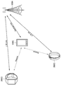
- FIG. 1 is an explanatory diagram for describing an example of a schematic configuration of a system 1 according to an embodiment of the present disclosure.
- the system 1 includes a wireless communication device 100 and a terminal device 200.
- the terminal device 200 is also called a user.
- the user may also be referred to as a UE.
- the wireless communication device 100C is also called UE-Relay.
- the UE here may be a UE defined in LTE or LTE-A, and the UE-Relay may be Prose UE to Network Relay as discussed in 3GPP, and more generally It may mean equipment.
- the wireless communication device 100 is a device that provides a wireless communication service to subordinate devices.
- the wireless communication device 100A is a base station of a cellular system (or mobile communication system).
- the base station 100A performs wireless communication with a device (for example, the terminal device 200A) located inside the cell 10A of the base station 100A.
- the base station 100A transmits a downlink signal to the terminal device 200A and receives an uplink signal from the terminal device 200A.
- the base station 100A is logically connected to other base stations through, for example, an X2 interface, and can transmit and receive control information and the like.
- the base station 100A is logically connected to a so-called core network (not shown) by, for example, an S1 interface, and can transmit and receive control information and the like. Note that communication between these devices can be physically relayed by various devices.
- the radio communication device 100A shown in FIG. 1 is a macro cell base station, and the cell 10A is a macro cell.
- the wireless communication devices 100B and 100C are master devices that operate the small cells 10B and 10C, respectively.
- the master device 100B is a small cell base station that is fixedly installed.
- the small cell base station 100B establishes a wireless backhaul link with the macro cell base station 100A and an access link with one or more terminal devices (for example, the terminal device 200B) in the small cell 10B.
- the wireless communication device 100B may be a relay node defined by 3GPP.
- the master device 100C is a dynamic AP (access point).
- the dynamic AP 100C is a mobile device that dynamically operates the small cell 10C.
- the dynamic AP 100C establishes a radio backhaul link with the macro cell base station 100A and an access link with one or more terminal devices (for example, the terminal device 200C) in the small cell 10C.
- the dynamic AP 100C may be, for example, a terminal device equipped with hardware or software that can operate as a base station or a wireless access point.
- the small cell 10C in this case is a locally formed network (Localized Network / Virtual Cell).
- the cell 10A is, for example, any wireless communication system such as LTE, LTE-A (LTE-Advanced), LTE-ADVANCED PRO, GSM (registered trademark), UMTS, W-CDMA, CDMA200, WiMAX, WiMAX2, or IEEE 802.16. May be operated according to
- the small cell is a concept that can include various types of cells (for example, femtocells, nanocells, picocells, and microcells) that are smaller than the macrocells and that are arranged so as to overlap or not overlap with the macrocells.
- the small cell is operated by a dedicated base station.
- the small cell is operated by a terminal serving as a master device temporarily operating as a small cell base station.
- So-called relay nodes can also be considered as a form of small cell base station.
- a wireless communication device that functions as a master station of a relay node is also referred to as a donor base station.
- the donor base station may mean a DeNB in LTE, and more generally may mean a parent station of a relay node.
- Terminal device 200 The terminal device 200 can communicate in a cellular system (or mobile communication system).
- the terminal device 200 performs wireless communication with a wireless communication device (for example, the base station 100A, the master device 100B, or 100C) of the cellular system.
- a wireless communication device for example, the base station 100A, the master device 100B, or 100C
- the terminal device 200A receives a downlink signal from the base station 100A and transmits an uplink signal to the base station 100A.
- the terminal device 200 is not limited to a so-called UE, and for example, a so-called low cost UE such as an MTC terminal, an eMTC (Enhanced MTC) terminal, and an NB-IoT terminal may be applied. .
- a so-called low cost UE such as an MTC terminal, an eMTC (Enhanced MTC) terminal, and an NB-IoT terminal may be applied.
- the present technology is not limited to the example illustrated in FIG.
- a configuration not including a master device SCE (Small Cell Enhancement), HetNet (Heterogeneous Network), an MTC network, or the like can be adopted.
- SCE Small Cell Enhancement
- HetNet Heterogeneous Network
- MTC network MTC network
- relay terminal 100C a terminal device that operates as a relay terminal
- remote terminal 200C a terminal device that operates as a remote terminal
- IoT Internet of Things
- 3GPP is standardizing communication methods specialized for IoT terminals such as MTC (Machine Type Communication) and NB-IoT (Narrow Band IoT).
- MTC Machine Type Communication
- NB-IoT Narrow Band IoT
- a typical example of a low cost terminal is a so-called wearable terminal.
- wearable terminals low power consumption and highly reliable communication are required, and large-capacity communication may be required depending on the situation.
- standardization of FeD2D was started in 2016 in 3GPP. Since wearable terminals exist in the vicinity of users themselves, using relay communication using a terminal device such as a smartphone can shorten the communication distance and achieve low power consumption and highly reliable communication. It becomes possible.
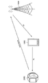
- FIG. 2 is an explanatory diagram for explaining an outline of communication via the relay terminal.
- relay terminal 100C a smart phone etc. which a user holds can be assumed, for example.
- a remote terminal 200C that communicates with the base station 100A via the relay terminal 100C for example, a wearable terminal or the like can be assumed.
- the relay terminal 100C performs, for example, so-called LTE communication (hereinafter also referred to as “backhaul link communication”) with the base station 100A, and performs side link communication with the remote terminal 200C.
- the remote terminal 200C communicates with the base station 100A via the relay terminal 100C.
- the relay terminal 100C can be a communication device that relays communication between the remote terminal 200C and the base station 100A.
- the remote terminal 200C can directly communicate with the base station 100A.
- the remote terminal 200C communicates with the base station 100A via the relay terminal 100C. It becomes important.
- relay communication is realized based on a conventional standard (for example, Enhanced D2D), IP relay is performed, and radio link communication (backhaul link) between the base station 100A and the relay terminal 100C is performed. Communication) and radio link communication (access link communication) between the relay terminal 100C and the remote terminal 200C are managed independently.
- FIG. 3 is an explanatory diagram for explaining an example of a schematic configuration of relay communication.
- An example of relay communication based on a conventional standard is transferred from the base station 100A to the remote terminal 200C via the relay terminal 100C. This is shown focusing on the case where data is transmitted.
- base station 100A performs predetermined transmission processing on data to be transmitted (also referred to as “user data”), performs encoding, modulation, and the like, and then transmits the user data to a relay terminal. Send to 100C.
- predetermined transmission processing on data to be transmitted also referred to as “user data”
- the relay terminal 100 ⁇ / b> C when the relay terminal 100 ⁇ / b> C receives user data from the base station 100 ⁇ / b> A, the relay terminal 100 ⁇ / b> C demodulates and decodes the user data and performs predetermined reproduction processing to acquire the user data. Then, the relay terminal 100C performs predetermined transmission processing on the acquired user data again, performs encoding and modulation, and transmits the user data to the remote terminal 200C. Further, when receiving remote user data from the relay terminal 100C, the remote terminal 200C demodulates and decodes the user data, and obtains the user data by performing a predetermined reproduction process.
- HARQ control is performed only on the backhaul link between the base station 100A and the relay terminal 100C, and on the access link between the relay terminal 100C and the remote terminal 200C. HARQ was not controlled.
- FIG. 4 is an explanatory diagram for describing an overview of relay communication in the system according to an embodiment of the present disclosure.
- the user data is demodulated and decoded in the relay terminal 100 ⁇ / b> C
- the user data is encoded and modulated again.
- Is transmitted to the remote terminal 200C that is, a layer 2 relay is introduced.
- wireless functions for example, retransmission control
- other than modulation, demodulation, encoding, and decoding processes are performed between the base station 100A and the remote terminal 200C. Process transparently.
- an example of a mechanism for guaranteeing communication quality with E2E is based on HARQ (Hybrid Automatic Repeat reQuest).
- HARQ Hybrid Automatic Repeat reQuest
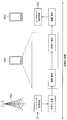
- FIG. 5 is a block diagram illustrating an exemplary configuration of the base station 100 according to an embodiment of the present disclosure.
- the base station 100 includes an antenna unit 110, a wireless communication unit 120, a network communication unit 130, a storage unit 140, and a processing unit 150.
- Antenna unit 110 The antenna unit 110 radiates a signal output from the wireless communication unit 120 to the space as a radio wave. Further, the antenna unit 110 converts radio waves in space into a signal and outputs the signal to the wireless communication unit 120.
- the wireless communication unit 120 transmits and receives signals.
- the radio communication unit 120 transmits a downlink signal to the terminal device and receives an uplink signal from the terminal device.
- the terminal device operates as a relay terminal (the wireless communication device 100C in FIG. 1), and the remote terminal (the terminal device 200C in FIG. 1) and the base station There is a case to relay communication between.
- the wireless communication unit 120 in the wireless communication device 100C corresponding to a relay terminal may transmit / receive a side link signal to / from a remote terminal.
- the network communication unit 130 transmits and receives information.
- the network communication unit 130 transmits information to other nodes and receives information from other nodes.
- the other nodes include other base stations and core network nodes.
- the terminal device may operate as a relay terminal and relay communication between the remote terminal and the base station.
- the wireless communication device 100C corresponding to the relay terminal may not include the network communication unit 130.
- Storage unit 140 The storage unit 140 temporarily or permanently stores a program for operating the base station 100 and various data.
- the processing unit 150 provides various functions of the base station 100.
- the processing unit 150 includes a communication processing unit 151, an information acquisition unit 153, a determination unit 155, and a notification unit 157.
- the processing unit 150 may further include other components other than these components. That is, the processing unit 150 can perform operations other than the operations of these components.
- the operations of the communication processing unit 151, the information acquisition unit 153, the determination unit 155, and the notification unit 157 will be described in detail later.
- FIG. 6 is a block diagram illustrating an exemplary configuration of the terminal device 200 according to an embodiment of the present disclosure.
- the terminal device 200 includes an antenna unit 210, a wireless communication unit 220, a storage unit 230, and a processing unit 240.
- Antenna unit 210 The antenna unit 210 radiates the signal output from the wireless communication unit 220 to the space as a radio wave. Further, the antenna unit 210 converts a radio wave in the space into a signal and outputs the signal to the wireless communication unit 220.
- the wireless communication unit 220 transmits and receives signals.
- the radio communication unit 220 receives a downlink signal from the base station and transmits an uplink signal to the base station.
- the terminal device may operate as a relay terminal and relay communication between the remote terminal and the base station.
- the radio communication unit 220 in the terminal device 200C operating as a remote terminal may transmit / receive a side link signal to / from the relay terminal.
- Storage unit 230 The storage unit 230 temporarily or permanently stores a program for operating the terminal device 200 and various data.
- the processing unit 240 provides various functions of the terminal device 200.
- the processing unit 240 includes a communication processing unit 241, an information acquisition unit 243, a determination unit 245, and a notification unit 247.
- the processing unit 240 may further include other components other than these components. That is, the processing unit 240 can perform operations other than the operations of these components.
- the operations of the communication processing unit 241, the information acquisition unit 243, the determination unit 245, and the notification unit 247 will be described in detail later.
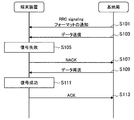
- FIG. 7 is an explanatory diagram for explaining an overview of HARQ, in which the base station 100 transmits data to the terminal apparatus 200, and the terminal apparatus 200 notifies the base station 100 of a data reception result. An example of the case is shown.
- the base station 100 (notification unit 157), based on RRC signaling, uses a control channel (for example, PUCCH (Physical Uplink) for the terminal device 200 to notify the base station 100 of ACK / NACK. Control Channel)) format is notified (S101).
- the base station 100 (communication processing unit 151) transmits data to the terminal device 200 (S103).
- the terminal device 200 When receiving the data transmitted from the base station 100, the terminal device 200 (communication processing unit 241) decodes the received data. Here, it is assumed that the terminal device 200 has failed to decode the data (S105). In this case, the terminal device 200 (notification unit 247) notifies the base station 100 of NACK based on the format notified from the base station 100 based on RRC signaling (S107). That is, the base station 100 (information acquisition unit 153) receives a NACK notification from the terminal device 200 as a response to the transmitted data. Accordingly, the base station 100 (determination unit 155) can recognize that the terminal device 200 has failed to receive data based on the notified NACK.
- the base station 100 (the communication processing unit 151) recognizes that the terminal device 200 has failed to receive data based on the NACK notified from the terminal device 200, the base station 100 (the communication processing unit 151) retransmits the data to the terminal device 200 ( S109).
- the terminal device 200 When receiving the data retransmitted from the base station 100, the terminal device 200 (communication processing unit 241) decodes the received data. Here, it is assumed that the terminal device 200 succeeds in decoding the data (S111). In this case, the terminal device 200 (notification unit 247) notifies the base station 100 of ACK based on the format notified from the base station 100 based on RRC signaling (S113). That is, the base station 100 (information acquisition unit 153) receives an ACK notification from the terminal device 200 as a response to the retransmitted data. Accordingly, the base station 100 (determination unit 155) can recognize that the terminal device 200 has successfully received data based on the notified ACK.
- the terminal device 200 may notify the base station 100 of an ACK in response to the successful decoding of the data transmitted from the base station 100 first. Needless to say, when the data retransmitted from the base station 100 is decoded, the terminal device 200 may notify the base station 100 of NACK again. Further, when notifying ACK or NACK to the base station 100, the terminal device 200 notifies the ACK or NACK based on so-called piggyback using PUSCH (Physical Uplink Shared Channel). Also good.
- PUSCH Physical Uplink Shared Channel
- the base station 100 notifies the terminal device 200 of ACK or NACK using PHICH (Physical HARQ Indicator Channel). do it.
- PHICH Physical HARQ Indicator Channel
- FIG. 8 is an explanatory diagram for explaining an overview of the system according to the present embodiment.
- the base station 100A allocates resources for notifying the reception result of data to both the backhaul link and the uplink, for example. Also good. As another example, the base station 100A may allocate a resource for notifying a data reception result only to the backhaul link, for example. In this case, the relay terminal 100C may execute resource allocation for notifying the data reception result to the access link. Based on such a mechanism, when the relay terminal 100C receives a data reception result (ACK / NACK) from the remote terminal 200C, the relay terminal 100C notifies the base station 100A of the reception result. Thereby, the base station 100A can recognize the reception result of the data transmitted to the remote terminal 200C at the remote terminal 200C.
- ACK / NACK data reception result
- a plurality of remote terminals 200C may be connected to the relay terminal 100C. Therefore, for example, when the number of remote terminals 200C connected to the relay terminal 100C increases, the relay terminal 100C indicates the data reception result (that is, the reception result notified from the remote terminal 200C) at the remote terminal 200C to the base station. More resources may be required to notify 100A.
- the base station 100A determines whether or not the backhaul link is in accordance with information related to the remote terminal 200C connected to the relay terminal 100C (for example, the number of remote terminals 200C). Controls the allocation of resources for notifying data reception results. By such control, for example, even when the number of remote terminals 200C connected to the relay terminal 100C increases, the relay terminal 100C notifies the base station 100A of the data reception result at the remote terminal 200C. It is possible to secure resources for doing so in a more preferable manner.
- the base station 100A, the relay terminal 100C, and the remote terminal 200C notify the data reception result (ACK / NACK) based on HARQ.
- ACK / NACK data reception result
- FIG. 9 is a sequence diagram illustrating an example of a series of processing flow of relay communication in the system according to the present embodiment, and in particular, a processing flow related to resource allocation for notifying ACK and NACK based on HARQ. Shows about.
- the remote terminal 200C and the relay terminal 100C establish communication via a wireless link (ie, access link) in order to transmit and receive data to each other (S201).
- the relay terminal 100C (notification unit 157) transmits information (for example, the number of serving terminals) related to the remote terminal 200C connected to the relay terminal 100C to the base station. 100A is notified (S203a).
- the remote terminal 200C (notifying unit 247) transmits information on the remote terminal 200C via a direct wireless link (hereinafter also referred to as “Uu link”) with the base station 100A. You may notify to a base station (S203b).
- the base station 100A based on the notified information on the remote terminal 200C, notifies the backhaul link with the relay terminal 100C of the data reception result (ACK / NACK) based on HARQ. Assign.
- base station 100A determines unit 155, based on the notified information on remote terminal 200C, receives data reception result (ACK) between base station 100A and relay terminal 100C. / NACK) resource available for notification is determined (S205). Then, the base station 100A (communication processing unit 151) allocates the resource determined based on the information regarding the remote terminal 200C to the backhaul link (S207). At this time, the base station 100A may allocate a resource pool that can be used for ACK and NACK notification to the backhaul link. As another example, base station 100A may schedule resources for performing notification of ACK and NACK, and allocate resources to the backhaul link based on the scheduling result.
- the base station 100A may determine resource blocks (for example, the number of resource blocks) necessary for notification of ACK and NACK based on the notified information on the remote terminal 200C. Details of processing related to the allocation of the resource to the backhaul link by the base station 100A will be described later.
- base station 100A notifies the data reception result (ACK / NACK) based on HARQ to the access link between relay terminal 100C and remote terminal 200C based on the notified information on remote terminal 200C. Resources may be allocated.
- the base station 100A may allocate a resource pool that can be used for notification of a data reception result (ACK / NACK) via the access link (Option 1).
- the base station 100A determines a resource pool that can be used for notification of ACK and NACK based on the notified information about the remote terminal 200C (S209a). Then, the base station 100A (communication processing unit 151) may allocate the resource pool determined based on the information regarding the remote terminal 200C to the access link (S211a).
- the base station 100A schedules a resource block for notifying a reception result (ACK / NACK) of data via the access link, and allocates resources to the access link based on the scheduling result. May be assigned (Option2).
- the base station 100A determines resource blocks (for example, the number of resource blocks) necessary for notification of ACK and NACK based on the notified information on the remote terminal 200C (S209b). Then, base station 100A (communication processing unit 151) may schedule resources for performing ACK and NACK according to the determination result of the resource block, and allocate resources to the access link based on the scheduling result ( S211b).
- the relay terminal 100C instead of the base station 100A may allocate resources available for ACK and NACK notification to the access link.
- the base station 100A transmits / receives data via the backhaul link between the relay terminal 100C and the base station 100A and transmits / receives data via the access link between the relay terminal 100C and the remote terminal 200C. And may be explicitly distinguished. Therefore, in the following description, ACK and NACK notified as a result of data transmission / reception via the backhaul link between the relay terminal 100C and the base station 100A are also referred to as “BL ACK” and “BL NACK”. The ACK and NACK notified as a result of data transmission / reception between the relay terminal 100C and the remote terminal 200C via the access link are also referred to as “AL ACK” and “AL NACK”.
- the remote terminal 200C executes reception processing of the data (S215).
- the remote terminal 200C uses the resource allocated to the access link as a reception result of the data transmitted from the relay terminal 100C, and sends an ACK (ie, ACK) to the relay terminal 100C. , AL ACK) is transmitted (S217).
- the relay terminal 100C uses the resource allocated to the backhaul link to base the data reception result on Transmit to the station 100A (S221). If a resource pool is allocated to the backhaul link at this time, the relay terminal 100C selects a transmission resource from the resource pool based on a predetermined condition (S219), and uses the transmission resource as the data. (S221).
- the data reception result for example, AL ACK
- the relay terminal 100C uses the resource allocated to the backhaul link to base the data reception result on Transmit to the station 100A (S221). If a resource pool is allocated to the backhaul link at this time, the relay terminal 100C selects a transmission resource from the resource pool based on a predetermined condition (S219), and uses the transmission resource as the data. (S221).
- the base station 100A performs blind decoding on the reception result of data transmitted from the relay terminal 100C via the backhaul link, for example, based on information held by the base station 100A at a predetermined timing. An attempt is made to decode the result (S223). Through the control as described above, the data reception result (that is, AL ACK / AL NACK) at the remote terminal 200C is notified to the base station 100A via the relay terminal 100C by E2E.
- the description has been given focusing on DL communication in which data is transmitted from the base station 100A to the remote terminal 200C via the relay terminal 100C, but the data reception result is notified.
- the processing related to resource allocation for the purpose is the same for UL communication. That is, in the UL communication, in the example shown in FIG. 9, the subject and the object may be interchanged in each of data transmission and notification of the reception result (ACK / NACK) of the data.
- the base station 100A allocates resources available for notification of ACK and NACK to the backhaul link based on information on the remote terminal 200C notified from the relay terminal 100C or the remote terminal 200C.
- the timing at which the base station 100A allocates the resource to the backhaul link may be set semi-statically or semi-statically from the network side, for example. The timing may be set dynamically.
- Examples of the information related to the remote terminal 200C include the number of remote terminals 200C connected to the relay terminal 100C (that is, the number of serving terminals), the traffic volume of the remote terminal 200C, and the like. With such a configuration, for example, even in a situation where AL ACK and AL NACK are transmitted from each of the plurality of remote terminals 200C connected to the relay terminal 100C to the base station 100A via the relay terminal 100C, sufficient An amount of resources can be secured.
- the base station 100A may change the format of the control channel (for example, PUCCH) for the relay terminal 100C to notify ACK and NACK based on the notified information on the remote terminal 200C.
- PUCCH control channel
- the base station 100A supports notification of ACK and NACK (that is, AL ACK and AL NACK) from the plurality of remote terminals 200C via the relay terminal 100C
- a format capable of simultaneously reporting ACK and NACK is assigned.
- An example of such a format is “Format 4” defined by 3GPP rules.
- not only the existing format but also a new format may be defined.
- a new format that can change the amount of resources allocated to notify ACK and NACK according to the number of remote terminals 200C connected to the relay terminal 100C is defined. Good.
- one control channel for example, for notifying ACK and NACK to the other
- PSCCH Physical Sidelink Control Channel
- the format assignment from the base station 100A to the relay terminal 100C and the remote terminal 200C may be performed based on, for example, predetermined signaling (for example, RRC signaling).
- predetermined signaling for example, RRC signaling
- the relay terminal 100C receives the AL ACK and AL NACK notification from the remote terminal 200C, and uses the so-called Piggy Back when notifying the base station 100A of the AL ACK and AL NACK. Good.
- relay terminal 100C when relay terminal 100C holds an uplink transmission signal, relay terminal 100C transmits AL ACK or AL NACK notified from remote terminal 200C to PUSCH when transmitting the uplink transmission signal. You can piggyback. Further, as another example, attention is paid to a case where the relay terminal 100C holds an uplink transmission signal and itself notifies the base station 100A of BL ACK or BL NACK.
- the relay terminal 100C when the relay terminal 100C transmits the uplink transmission signal, the relay terminal 100C receives the BL ACK or BL NACK notified to the base station 100A and the AL ACK or AL NACK notified from the remote terminal 200C. You may piggyback to PUSCH.
- the base station 100A allocates a resource pool that can be used for ACK and NACK notification to the backhaul link based on the information about the remote terminal 200C notified from the relay terminal 100C or the remote terminal 200C. At this time, the base station 100A has a sufficient amount of resources for the relay terminal 100C to notify the base station 100A of the ACK and NACK notified from the one or more remote terminals 200C based on the notified information about the remote terminal 200C.
- the resource pool size is determined so that it can be secured.
- the base station 100A may notify at least one of the relay terminal 100C and the remote terminal 200C whether or not to perform feedback transmission using a resource pool that can be used for notification of ACK and NACK.
- the relay terminal 100C or the remote terminal 200C may notify the base station 100A of information related to the remote terminal 200C.
- the base station 100A may assign the resource pool that can be used for notification of ACK and NACK to the relay terminal 100C by semi-statically assigning to the PUSCH or PDSCH. Also, the base station 100A may be assigned so as to satisfy, for example, a HARQ round drip time.
- the base station 100A includes, for example, a period, a period, offset information from a reference point (SFN (System Frame Number), etc.), pool time frequency information, etc.
- the relay terminal 100C may be notified using SIB (System Information Block) or the like.
- the relay terminal 100C selects a resource used for transmission of ACK and NACK (for example, BL ACK, BL NACK, AL ACK, or AL NACK) to the base station 100A from the resource pool allocated by the base station 100A.
- ACK and NACK for example, BL ACK, BL NACK, AL ACK, or AL NACK
- the relay terminal 100C selects a resource for notifying the base station 100A of AL ACK and AL NACK notified from the remote terminal 200C based on a predetermined condition.
- the relay terminal 100C selects information on the remote terminal 200C (for example, terminal identification information, data retransmission count, transmission packet priority information, remote terminal 200C position information, and the like). It may be used as a condition for this.
- the relay terminal 100C may use information for managing the remote terminal 200C in the relay terminal 100C as a condition for selecting the resource.
- Examples of the information for managing the remote terminal 200C in the relay terminal 100C include, for example, identification information of the remote terminal 200C (information given from the relay terminal 100C, the base station 100A, or a higher layer), packet priority Information, terminal priority information, and the like. Note that the relay terminal 100C may use at least a part of the information described above as a condition for selecting the resource.
- a common condition is set between the base station 100A and the relay terminal 100C as a predetermined condition for the relay terminal 100C to select a resource to be used for transmission of ACK and NACK from the resource pool. Therefore, the predetermined condition may be notified from the base station 100A to the relay terminal 100C, for example. With such a configuration, the base station 100A can recognize which of the resources in the resource pool is used for notification of AL ACK and AL NACK from which remote terminal 200C. .
- the relay terminal 100C may multiplex, for example, AL ACK or AL NACK notified from one or more remote terminals 200C and transmit it to the base station 100A.
- relay terminal 100C may notify base station 100A that AL ACK or AL NACK has been multiplexed and information related to remote terminal 200C in which AL ACK or AL NACK has been multiplexed.
- the relay terminal 100C may perform multiplexing for each of various priorities such as packet priority and terminal priority.
- the base station 100A may allocate a resource pool when allocating resources to the access link (Option 1), or may allocate resources based on scheduling results of ACK and NACK notification ( Option2).
- the base station 100A transmits information on setting of resources that can be used for notification of ACK and NACK assigned to the access link to at least one of the relay terminal 100C and the remote terminal 200C at a predetermined timing. Notification may be made in advance. Note that the timing at which the base station 100A performs the notification may be set to be semi-static from the network side, or may be fixedly set. The timing may be set dynamically.
- the base station 100A determines that the resource pool information (eg, period, period, offset information from a reference point (SFN, etc.), pool time, etc. Frequency information, etc.) may be notified to at least one of the relay terminal 100C and the remote terminal 200C using SIB or the like.
- the base station 100A may notify the remote terminal 200C directly via the Uu link or via the relay terminal 100C. Notification may be made indirectly by relay communication.
- a resource pool is allocated to an access link (Option 1)
- communication via the access link may be encoded based on a predetermined encoding method.
- different orthogonal codes may be assigned to each relay terminal 100C or each remote terminal 200C, and other non-orthogonal multiplexing schemes may be used.
- the remote terminal 200C randomly selects a resource for notifying the relay terminal 100C of ACK and NACK from the resource pool at a predetermined timing. May be.
- the timing at which the remote terminal 200C selects a resource from the resource pool may be set semi-statically or semi-statically from the network side, for example. The timing may be set dynamically.
- the remote terminal 200C may select a resource for notifying the relay terminal 100C of ACK and NACK from the resource pool based on a predetermined condition.
- the remote terminal 200C has its own terminal identification information, the number of times of data retransmission, the priority information of the transmission packet, its own position information, and its own terminal identification information (relay terminal 100C managed on the relay terminal 100C side).
- the resource may be selected from the resource pool using at least part of the information (information given from the base station 100A or a higher layer).
- the remote terminal 200C may use resources instructed from the base station 100A or the relay terminal 100C.
- the remote terminal 200C selects a resource to be used for the notification from the resource pool focusing on the case where the remote terminal 200C notifies the relay terminal 100C of ACK and NACK. did.
- the relay terminal 100C selects a resource from the resource pool in the same manner as described above. Also good.
- the base station 100A may notify information regarding the scheduled resource block (for example, resource block position information) to at least one of the relay terminal 100C and the remote terminal 200C.
- the base station 100A may directly notify the remote terminal 200C via the Uu link, or via the relay terminal 100C. Notification may be made indirectly by relay communication.
- the timing at which the base station 100A allocates the resource pool may be set semi-statically or semi-statically from the network side, for example.
- the timing may be set dynamically.
- the base station 100A when the base station 100A does not use a resource (ie, SPS (Semi Persistent Scheduling) resource) allocated in a semi-static manner in advance (that is, when it is not activated), the base station 100A allocates the resource. It may be used for other purposes.
- a resource ie, SPS (Semi Persistent Scheduling) resource
- the base station 100A determines the data reception result (ACK / NACK) for the backhaul link according to the information about the remote terminal 200C connected to the relay terminal 100C. ) Control resource allocation for notification. In addition, base station 100A may control allocation of resources for notifying a data reception result (ACK / NACK) to an access link according to information related to remote terminal 200C.
- Second Embodiment >> ⁇ 4.1. Overview> Subsequently, as a second embodiment, an example of a mechanism for realizing data retransmission control based on HARQ in relay communication via the relay terminal 100C between the base station 100A and the remote terminal 200C will be described.
- FIG. 10 is an explanatory diagram for explaining an overview of the system according to the present embodiment.
- the relay terminal 100C between the base station 100A and the remote terminal 200C, between the base station 100A and the relay terminal 100C (that is, the backhaul link), between the relay terminal 100C and the remote terminal 200C.
- Data transmission / reception is performed during each period (ie, access link). Therefore, for example, when data is transmitted from the base station 100A to the remote terminal 200C via the relay terminal 100C, even if the data transmission via the backhaul link is successful, the data transmission via the access link is performed. May fail.
- resources allocated to access links are often more limited than resources allocated to backhaul links. For this reason, communication via the access link may be likely to be a resource shortage compared to communication via the backhaul link.
- the base station 100A fails to perform the failure. May be difficult to recognize. Therefore, in relay communication via the relay terminal 100C between the base station 100A and the remote terminal 200C, it may be difficult to guarantee the link quality with E2E.
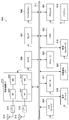
- FIG. 11 is a flowchart illustrating an example of a flow of a series of processes of the system according to the present embodiment.
- the relay terminal 100C relay-transmits data transmitted from the base station 100A to the remote terminal 200C (hereinafter referred to as “DL communication”). (It will also be called).
- the base station 100A controls communication related to data transmission to the remote terminal 200C based on the fed back information (S307). For example, the base station 100A changes various settings related to communication between the relay terminal 100C and the remote terminal 200C via the access link based on the fed back information, and is at least one of the relay terminal 100C and the remote terminal 200C. You may instruct. Further, the base station 100A may control resource allocation to the access link. The base station 100A may instruct at least one of the relay terminal 100C and the remote terminal 200C to switch the radio link used for data transmission (retransmission) based on the fed back information.
- base station 100A may instruct relay terminal 100C to retransmit data. Further, as another example, when the relay terminal 100C receives an instruction or the like related to the change of the setting from the base station 100A, the data retransmission may be performed.
- the remote terminal 200C succeeds in decoding the data and transmits AL NACK directly or indirectly to the base station 100A.
- the base station 100A (information acquisition unit 153) receives the AL ACK from the remote terminal 200C (S303, YES), and ends a series of processes related to the transmission of the data.
- the system according to the present embodiment realizes retransmission control in a more preferable manner in relay communication via the relay terminal 100C between the base station 100A and the remote terminal 200C, and eventually by E2E. It is possible to guarantee the link quality.
- retransmission control based on HARQ is realized in relay communication via the relay terminal 100C between the base station 100A and the remote terminal 200C.
- An example of a mechanism for doing this has been described.
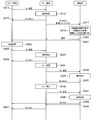
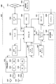
- FIG. 12 is a sequence diagram illustrating an example of a series of processing flow of relay communication in the system according to the present embodiment, and illustrates an example of retransmission control in DL communication.
- the base station 100A (communication processing unit 151) transmits data to the relay terminal 100C via the backhaul link (S311), and the relay terminal 100C (communication processing unit 151) Assume that decoding of the data has failed (S313).
- the relay terminal 100C (notification unit 157) notifies BL NACK to the base station 100A (S315).
- the base station 100A executes the data retransmission processing (S317, S319).
- the relay terminal 100C succeeds in decoding the data retransmitted from the base station 100A (S321).
- the relay terminal 100C (notification unit 157) notifies the base station 100A of BL ACK (S323).
- the base station 100A can recognize that the retransmission of data to the relay terminal 100C via the backhaul link has succeeded.
- the relay terminal 100C (communication processing unit 151) relays the data received from the base station 100A via the access link to the remote terminal 200C that is the transmission destination of the data (S325, S327).
- the remote terminal 200C has failed to decode the data transmitted from the relay terminal 100C (S329).
- the remote terminal 200C (notifying unit 247) notifies the base station 100A and the relay terminal 100C of AL NACK, and also provides information on the reception result of the data transmitted from the relay terminal 100C. Feedback to 100A.
- the remote terminal 200C may perform AL NACK notification and feedback of the information based on indirect communication (ie, relay communication) via the relay terminal 100C to the base station 100A. Good (S331, S333).
- the remote terminal 200C may perform notification of AL NACK and feedback of the above information based on direct communication via the Uu link to the base station 100A (S335).
- the feedback notification method is not particularly limited as long as the feedback of information related to the reception result of the data transmitted from the relay terminal 100C is associated with the AL NACK notification from the remote terminal 200C.
- the base station 100A Upon receiving the AL NACK notification and the feedback of the information related to the data reception result from the remote terminal 200C, the base station 100A (communication processing unit 151) receives direct or indirect communication with the remote terminal 200C. Control of communication (in other words, E2E communication with the remote terminal 200C) is executed (S337, S339).
- the base station 100A changes various settings related to communication between the relay terminal 100C and the remote terminal 200C via the access link based on the fed back information. You may instruct
- the base station 100A also instructs at least one of the relay terminal 100C and the remote terminal 200C to switch the radio link used for data transmission (retransmission) based on the fed back information. May be.
- the base station 100A is configured such that the relay terminal 100C used for relay communication with the remote terminal 200C is handed over to the other relay terminal 100C. An instruction may be given to at least one of them.
- the base station 100A switches the communication with the remote terminal 200C from the communication through the relay terminal 100C to the direct communication through the Uu link (falls back). You may give instructions to them. Further, the base station 100A may control resource allocation to the access link.
- the relay terminal 100C (communication processing unit 151) executes retransmission processing of the data via the access link with respect to the remote terminal 200C (S341, S343).
- the remote terminal 200C succeeds in decoding the data retransmitted from the relay terminal 100C (S345).
- remote terminal 200C (notification unit 247) notifies AL ACK to base station 100A and relay terminal 100C.
- the remote terminal 200C may notify the base station 100A of AL ACK based on indirect communication (that is, relay communication) via the relay terminal 100C (S347, S349).
- the remote terminal 200C may notify the base station 100A of AL NACK based on direct communication via the Uu link (S351).
- the base station 100A can recognize that the relay transmission of data from the relay terminal 100C to the remote terminal 200C via the access link is successful.
- FIG. 13 is a sequence diagram illustrating another example of a series of processing flow of relay communication in the system according to the present embodiment, and illustrates an example of retransmission control in UL communication.
- the remote terminal 200C (communication processing unit 241) transmits data to the relay terminal 100C via the access link (S411), and the relay terminal 100C (communication processing unit 151) It is assumed that decoding of the data has failed (S413).
- the relay terminal 100C (notification unit 157) notifies the remote terminal 200C of AL NACK (S415). That is, the remote terminal 200C (information acquisition unit 243) receives a notification of AL NACK from the relay terminal 100C as a response to the transmitted data.
- relay terminal 100C (notification unit 157) performs notification of AL NACK from remote terminal 200C and feedback of information related to the reception result of data transmitted from remote terminal 200C to base station 100A ( S417).
- the feedback notification method is not particularly limited.
- the base station 100A (communication processing unit 151) receives the AL NACK notification and the feedback of the information related to the data reception result from the relay terminal 100C
- the base station 100A (communication processing unit 151) directly or indirectly between the corresponding remote terminal 200C Control (in other words, E2E communication with the remote terminal 200C) is executed (S419, S421).
- E2E communication with the remote terminal 200C is executed (S419, S421).
- the details of the control are the same as in the case of the DL communication described above, and thus detailed description thereof is omitted.
- the remote terminal 200C executes retransmission processing of the data via the access link for the relay terminal 100C (S423, S425).
- the relay terminal 100C succeeds in decoding the data retransmitted from the remote terminal 200C (S427).
- relay terminal 100C notification unit 157) notifies AL ACK to remote terminal 200C (S429). That is, the remote terminal 200C (information acquisition unit 243) receives an AL ACK notification from the relay terminal 100C as a response to the retransmitted data.
- the remote terminal 200C determination unit 245) can recognize that the data transmission to the relay terminal 100C via the access link is successful.
- the relay terminal 100C (communication processing unit 151) relays the data received from the remote terminal 200C to the base station 100A via the backhaul link (S431, S433).
- the base station 100A has failed to decode the data transmitted from the relay terminal 100C (S435).
- the base station 100A (notification unit 157) notifies BL NACK to the relay terminal 100C (S437).
- the relay terminal 100C When the relay terminal 100C receives a BL NACK from the base station 100A as a result of data transmission to the base station 100A, the relay terminal 100C executes retransmission processing of the data (S439, S441).
- the base station 100A succeeds in decoding the data retransmitted from the relay terminal 100C (S443).
- base station 100A (notification unit 157) notifies BL ACK to relay terminal 100C and remote terminal 200C.
- the base station 100A may notify the BL ACK to the remote terminal 200C based on indirect communication (ie, relay communication) via the relay terminal 100C (S445, S447).
- the base station 100A may notify the BL ACK to the remote terminal 200C based on direct communication via the Uu link (S449). That is, the remote terminal 200C (information acquisition unit 243) receives a BL ACK notification from the base station 100A as a reception result of the transmitted data based on direct or indirect communication. Thereby, the remote terminal 200C (determination unit 245) can recognize that the relay transmission of data from the relay terminal 100C to the base station 100A via the backhaul link has been successful.
- the data transmission / reception result (BL ACK and BL NACK) via the backhaul link and the data transmission / reception result (AL ACK and AL NACK) is explicitly distinguished. At least a part of BL ACK and BL NACK transmitted / received between relay terminal 100C and base station 100A, and AL ACK and AL NACK transmitted / received between relay terminal 100C and each remote terminal 200C.
- the plurality of pieces of information may be multiplexed and transmitted.
- Example of feedback method The remote terminal 200C feeds back information to the base station 100A as a method of performing feedback indirectly through relay communication via the relay terminal 100C, or directly via a Uu link. And a method of providing feedback.
- the information feedback via the access link between the remote terminal 200C and the relay terminal 100C includes PSCCH or PSSCH ( Physical (Sidelink Shared Channel) can be used.
- PSCCH or PSSCH Physical (Sidelink Shared Channel) can be used.
- PUCCH or PUSCH can be used for feedback of information via the backhaul link between the relay terminal 100C and the base station 100A.
- PDCCH or PDSCH may be used for feedback of information via a backhaul link between relay terminal 100C and base station 100A.
- PUCCH or PUSCH can be used for the feedback.
- PDCCH or PDSCH may be used for the feedback via the Uu link.
- feedback from the remote terminal 200C or the relay terminal 100C to the base station 100A may be executed using a determination result based on a predetermined condition as a trigger.
- a condition that triggers feedback (for example, a threshold for determination) may be set to be semi-static from the base station 100A or a higher layer, for example, and fixedly. It may be set. Further, the condition may be set dynamically.
- the conditions that trigger the feedback include, for example, the number of times data transmission through the access link has failed, information on the communication quality of the access link (for example, the result of RRM measurement for the access link (side link)), and the like. Can be mentioned.
- information related to the resource pool for example, the use status of resources in the resource pool (congestion status)
- a sensing result of resource usage in a predetermined resource pool or a predetermined frequency band may be used as a condition that triggers feedback.
- the remote terminal 200C may perform feedback to the base station 100A or the relay terminal 100C when the various information exceeds a threshold value.
- 100 C of relay terminals may perform feedback with respect to 100 A of base stations, when the various information mentioned above exceeds a threshold value.
- the relay terminal 100C determines a condition that triggers feedback for the base station 100A
- the number of remote terminals 200C that have fed back to the relay terminal 100C may be used as the condition. Good.
- the relay terminal 100C may perform feedback to the base station 100A when the number of remote terminals 200C that have performed feedback to the relay terminal 100C exceeds a threshold.
- a period for collecting information used for determining whether to perform feedback may be set.
- the remote terminal 200C or the relay terminal 100C may perform feedback of information to the base station 100A when a condition that triggers feedback is satisfied during the window period.
- the base station 100A may set the start (End) and end (Duration) of the window period for the remote terminal 200C or the relay terminal 100C.
- the remote terminal 200C or the relay terminal 100C may clear the counter of information that has been counted during the window period.
- FIG. 14 is an explanatory diagram for explaining an aspect of the operation of the system according to the present embodiment, and shows an outline of the operation of the base station 100A that has received feedback from the remote terminal 200C.
- the relay terminal 100C relay-transmits data transmitted from the base station 100A to the relay terminal 100C
- the resource of the access link is insufficient, and the relay transmission is not performed.
- the remote terminal 200C notifies the base station 100A directly or indirectly that the transmission of the data has failed.
- the base station 100A receives feedback of information related to transmission / reception of the data via the access link from the remote terminal 200C or the relay terminal 100C, and executes a countermeasure corresponding to the feedback. Therefore, an example of countermeasures executed by the base station 100A according to feedback will be described below.
- (3-1) Data Retransmission Instruction When the base station 100A receives feedback from the remote terminal 200C or the relay terminal 100C, the base station 100A determines whether to transmit the data of the remote terminal 200C or the relay terminal 100C according to the feedback. The transmission source may be instructed to retransmit data.
- Transmission mode control when data is retransmitted, a communication mode (that is, transmission mode) in data retransmission via the access link between the remote terminal 200C and the relay terminal 100C may be controlled.
- the base station 100A selects any one of the following modes 1 to 3 and switches to the selected mode based on a predetermined indicator (for example, Mode Indicator). And at least one of the relay terminals 100C.
- mode 1 is a mode in which base station 100A schedules a resource block to be used for data transmission via an access link, and instructs the resource block to remote terminal 200C or relay terminal 100C.
- mode 2 is a mode in which the remote terminal 200C or the relay terminal 100C itself selects a resource to be used for data transmission from a resource pool that can be used for data transmission via the access link.
- the resource pool may be set by the base station 100A, or may be set in advance (may be pre-configured).
- Mode 3 is used for data transmission via the access link from the resource pool (hereinafter also referred to as “relay resource pool”) that can be used by the relay terminal 100C for data transmission via the access link.
- the relay resource pool may be set by the base station 100A, or may be set in advance (may be pre-configured).
- Resource pool control In addition, when data is retransmitted, the setting of a resource pool that can be used for data transmission via an access link may be controlled.
- the base station 100A may reset the resource pool so that the size of the resource pool becomes larger when there are not enough resources available for data transmission / reception via the access link. Additional allocations may be made.
- the base station 100A may change a resource pool that has already been set as another resource pool as a resource pool that can be used for data transmission via the access link.
- the base station 100A may apply the frequency hopping setting for the use of the resource pool.
- the base station 100A may provide information related to frequency hopping settings to the remote terminal 200C or the relay terminal 100C.
- the base station 100A may notify the remote terminal 200C or the relay terminal 100C of information regarding the resource pool after the setting change.
- information regarding the resource pool notified at this time for example, information regarding the frequency domain and information regarding the time domain may be cited.
- Examples of information on the frequency domain include PRB (Physical Resource Block) start position (PRB Start), PRB end position (PRB End), the number of PRBs, and subchannel information.
- examples of information related to the time domain include a bitmap indicator, a subframe number, and a frame number.
- the base station 100A may notify the remote terminal 200C or the relay terminal 100C of the resource pool hopping flag. Further, base station 100A may instruct remote terminal 200C or relay terminal 100C with a hopping pattern using a resource pool popping indicator.
- Parameters related to data transmission via the access link include, for example, transport block size (Transport Block Size), modulation method (Modulation Scheme), resource block allocation (Allocated Resource Blocks), and data block to be retransmitted. For example, an iterative version (Redundancy Version) representing a feature.
- Transport Block Size Transport Block Size
- Modulation Scheme Modulation Scheme
- Resource Block allocation Allocated Resource Blocks
- Data block to be retransmitted For example, an iterative version (Redundancy Version) representing a feature.
- an iterative version representing a feature.
- These parameters may be directly assigned and controlled by limiting the parameter selection range. In the case of control for limiting the parameter selection range, the parameter selection range may be controlled by defining several modes and assigning specific modes.
- the base station 100A may directly notify the remote terminal 200C of information related to the above setting using DCI (Downlink Control Information) or SIB (System Information Block).
- the base station 100A may indirectly notify the remote terminal 200C of information regarding the setting via the relay terminal 100C.
- the notification of the information from the base station 100A to the relay terminal 100C may be performed using DCI or SIB, for example.
- the notification of the information from the relay terminal 100C to the remote terminal 200C may be performed using, for example, SCI (Sidelink Control Information).
- the above setting at the time of data retransmission may be selected by the terminal itself that is the data transmission source among the remote terminal 200C and the relay terminal 100C.
- the setting range that the remote terminal 200C and the relay terminal 100C select when retransmitting data may be instructed from the base station 100A or the network side, for example.
- DCI or SIB can be used.
- the relay terminal 100C may notify the remote terminal 200C of information regarding the setting using the SCI.
- the base station 100A may switch the relay terminal 100C used for relay communication with the remote terminal 200C to another relay terminal 100C (that is, handover or reselection). .
- the base station 100A may notify the relay terminal 100C as a switching destination of the switching request (that is, a handover request or a reselection request). That is, the relay terminal 100C as the switching destination may start various processes related to handover or reselection in response to the request from the base station 100A.
- the base station 100A may notify a handover request or reselection request message to a candidate for the relay terminal 100C located in the vicinity.
- the base station 100A may notify the candidate of the relay terminal 100C located nearby by using a discovery signal, for example, a handover request message or a reselection request message.
- the base station 100A may notify the remote terminal 200C of a request for switching the relay terminal 100C (that is, a handover request or a reselection request). In this case, for example, the base station 100A may notify the remote terminal 200C of the switching request directly via the Uu link. As another example, the base station 100A may indirectly notify the switching request to the remote terminal 200C via the relay terminal 100C. In addition, the remote terminal 200C may start various processes related to handover or reselection in response to the request from the base station 100A.
- the base station 100A may switch communication with the remote terminal 200C from relay communication via the relay terminal 100C to direct communication via the Uu link.
- the base station 100A uses the relay terminal 100C used for relay communication based on a so-called CoMP (Coordinated Multi-Point) technique.
- CoMP Coordinatd Multi-Point
- the base station 100A newly sets a relay terminal 100C used for CoMP transmission. Then, the base station 100A transmits data to the remote terminal 200C via the plurality of relay terminals 100C by CoMP transmission using the plurality of relay terminals 100C including the newly set relay terminal 100C. At this time, the base station 100A applies the CoMP transmission to the relay communication via the relay terminal 100C between the base station 100A and the remote terminal 200C, and the plurality of relay terminals 100C used for CoMP transmission. To instruct.
- a CoMP transmission method for example, a method such as Joint Transmission that simultaneously transmits the same data from a plurality of relay terminals 100C, or Dynamic Relay selection that instantaneously switches a transmission link is used.
- the base station 100A may instruct each of the plurality of relay terminals 100C used for CoMP transmission to transmit different RVs (Redundancy Versions).
- the base station 100A or the remote terminal 200C may instruct information related to resources used for CoMP transmission to each of the plurality of relay terminals 100C used for CoMP transmission.
- the base station 100A feeds back information related to data transmission / reception via the access link in relay communication with the remote terminal 200C via the relay terminal 100C. Is received from at least one of the remote terminal 200C and the relay terminal 100C.
- the base station 100A receives the feedback of the information related to the transmission / reception of the data, and then performs direct or indirect communication with the remote terminal 200C corresponding to the information (in other words, E2E with the remote terminal 200C). Control).
- the system according to the present embodiment realizes retransmission control in a more preferable manner in relay communication via the relay terminal 100C between the base station 100A and the remote terminal 200C, and eventually by E2E. It is possible to guarantee the link quality.
- radio access methods between communication via the access link from the relay terminal 100C to the remote terminal 200C and communication via the Uu link from the base station 100A to the remote terminal 200C (DL communication). May be used.
- a single carrier radio access method called SC-FDMA (Single Carrier-Frequency Division Multiple Access) is used. Is done.
- SC-FDMA Single Carrier-Frequency Division Multiple Access
- OFDMA Orthogonal frequency-division multiple access
- some terminal devices that operate as the remote terminal 200C require low power consumption.
- a receiver corresponding to each of a plurality of wireless access methods is provided for the terminal device, power consumption tends to be higher.
- Some terminal devices operating as the remote terminal 200C are required to be low in cost, such as so-called low cost terminals. Therefore, it may be assumed that only the receiver corresponding to any of the wireless access methods as described above is provided as the remote terminal 200C. From such a situation, it may be assumed that so-called unidirectional communication is applied in relay communication via the relay terminal 100C between the base station 100A and the remote terminal 200C.
- FIG.15 and FIG.16 is explanatory drawing for demonstrating the outline
- the example illustrated in FIG. 16 illustrates an example of a configuration of unidirectional communication in a case where the remote terminal 200C includes only a receiver that supports SC-FDMA as a wireless communication receiver.
- the remote terminal 200C can receive data transmitted from the relay terminal 100C based on the SC-FDMA scheme, but cannot receive data transmitted from the base station 100A based on the OFDMA scheme. Have difficulty. Therefore, the remote terminal 200C receives data transmitted from the base station 100A based on relay communication via the relay terminal 100C.
- the remote terminal 200C determines that the reception result (ACK / NACK) of the data received from the base station 100A via the relay terminal 100C is based on communication with the base station 100A via the Uu link. Directly notify the station 100A.
- the base station 100A and the remote terminal 200C HARQ control can be realized in relay communication via the relay terminal 100C.
- the remote terminal 200C fails to decode data received from the base station 100A in the example shown in FIG.
- the process related to the retransmission of the data is executed by the base station 100A after the NACK transmitted from the remote terminal 200C is received by the base station 100A via the relay terminal 100C.
- the remote terminal 200C fails to decode data received from the base station 100A in the example shown in FIG.
- the remote terminal 200C can notify the NACK directly to the base station 100A.
- retransmission of data from the base station 100A to the remote terminal 200C is performed again by relay communication via the relay terminal 100C. That is, the data retransmitted by the base station 100A is received by the relay terminal 100C, and the relay terminal 100C relays the data to the remote terminal 200C.
- the relay terminal 100C when the remote terminal 200C fails to decode the data transmitted from the base station 100A, the relay terminal 100C replaces the retransmission of the data with the base station 100A. Do on behalf.
- the fact that the relay terminal 100C resends data on behalf is also referred to as “proxy transmission”.
- data is retransmitted from the relay terminal 100C to the remote terminal 200C without directly or indirectly retransmitting data from the base station 100A to the remote terminal 200C.
- the remote terminal 200C receives data directly from the base station 100A via the Uu link (see FIG. 15) and indirectly receives data via the relay terminal 100C (see FIG. 15). (See FIG. 16).
- FIG. 17 is a sequence diagram illustrating an example of a flow of a series of processes of the system according to the present embodiment.
- the base station 100A sets the relay terminal 100C used for proxy transmission at the time of retransmission control in relay communication with the remote terminal 200C via the relay terminal 100C (S501).
- the base station 100A (notification unit 157) may notify the relay terminal 100C selected to be used for proxy transmission that it will be used for proxy transmission at the time of retransmission control. You may notify the setting regarding transmission, etc.
- the base station 100A transmits data (DL signal) to the remote terminal 200C via the Uu link (S503).
- the base station 100A (communication processing unit 151) transmits the data transmitted to the remote terminal 200C via the backhaul link to the relay terminal 100C used for proxy transmission at the time of retransmission control (S505).
- the remote terminal 200C fails to decode the data transmitted from the base station 100A (S507), and the relay terminal 100C succeeds in decoding the data transmitted from the base station 100A (S509).
- the relay terminal 100C (notification unit 157) succeeds in decoding the data (DL signal) transmitted from the base station 100A (S509)
- the relay terminal 100C (notification unit 157) may transmit an ACK to the base station 100A (S511).
- the remote terminal 200C When the remote terminal 200C fails to decode the data transmitted from the base station 100A (S507), the remote terminal 200C transmits a NACK to the relay terminal 100C via the access link (S513).
- the relay terminal 100C (communication processing unit 151) retransmits the data (DL signal) received from the base station 100A in advance to the remote terminal 200C as a proxy for the base station 100A. (S515, S517). At this time, the relay terminal 100C retransmits data to the remote terminal 200C based on the same radio access scheme (for example, OFDMA) as when the base station 100A transmits data to the remote terminal 200C.
- OFDMA radio access scheme
- the relay terminal 100C (notification unit 157) retransmits data to the remote terminal 200C as a proxy of the base station 100A
- the relay terminal 100C notifies the base station 100A that the data has been retransmitted by proxy ( S519).
- the base station 100A can recognize that it is not necessary to execute a process related to retransmission of data to the remote terminal 200C.
- the remote terminal 200C succeeds in decoding the data retransmitted from the relay terminal 100C on behalf of the base station 100A (S521).
- the remote terminal 200C (notification unit 247) notifies the relay terminal 100C of ACK (S523).
- the relay terminal 100C (notifying unit 157) relays the notified ACK to the base station 100A (S525).
- the base station 100A (determination unit 155) can recognize that the data (DL signal) transmitted to the remote terminal 200C has been correctly received by the remote terminal 200C.
- the base station 100A sets the relay terminal 100C used for proxy transmission at the time of retransmission control in relay communication with the remote terminal 200C via the relay terminal 100C (S551).
- the base station 100A (notification unit 157) may notify the relay terminal 100C selected to be used for proxy transmission that it will be used for proxy transmission at the time of retransmission control. You may notify the setting regarding transmission, etc.
- the base station 100A (communication processing unit 151) transmits data (DL signal) to be transmitted to the remote terminal 200C to the relay terminal 100C to which the remote terminal 200C is connected via the backhaul link (S553).
- the relay terminal 100C succeeds in decoding the data (S555).
- the relay terminal 100C (notification unit 157) notifies the base station 100 of ACK (S557). Accordingly, the base station 100 (determination unit 155) can recognize that the relay terminal 100C has successfully received data based on the notified ACK.
- the relay terminal 100C (communication processing unit 151) relays the data (DL signal) received from the base station 100A to the remote terminal 200C that is the transmission destination of the data via the access link (S559). ).
- the remote terminal 200C has failed to decode the data (S661).
- the remote terminal 200C (notification unit 247) notifies NACK to the base station 100A based on direct communication via the Uu link (S563).
- the relay terminal 100C decodes NACK transmitted directly from the remote terminal 200C to the base station 100A by blind-decoding data transmitted from the remote terminal 200C (S565).
- the relay terminal 100C (determination unit 155) can recognize that the remote terminal 200C has failed to receive data.
- the base station 100A may notify the relay terminal 100C in advance of information on the resource to which the NACK signal is transmitted at this time.
- a notification of NACK by the remote terminal 200C may be notified to the relay terminal 100C via the base station 100A.
- the base station 100A transfers the notified NACK to the relay terminal 100C instead of retransmitting the data that the remote terminal 200C has failed to decode. May be.
- the relay terminal 100C (determination unit 155) can recognize that the remote terminal 200C has failed to receive data.
- the relay terminal 100C When the relay terminal 100C recognizes that the remote terminal 200C has failed to receive data, the relay terminal 100C executes processing related to retransmission of the data to the remote terminal 200C. At this time, the relay terminal 100C (notification unit 157) first sends it to the base station 100A. Notification of resending data on behalf is sent (S567). Thereby, it becomes possible for base station 100A to recognize that it is not necessary to execute processing related to retransmission of data via relay terminal 100C to remote terminal 200C. In addition, the relay terminal 100C (communication processing unit 151) retransmits data that the remote terminal 200C has failed to receive, that is, data (DL signal) previously received from the base station 100A to the remote terminal 200C (S571).
- data DL signal
- the remote terminal 200C succeeds in decoding the data retransmitted from the relay terminal 100C (S571).
- the remote terminal 200C (notification unit 247) notifies the base station 100A of ACK based on direct communication via the Uu link (S575).
- the base station 100A (determination unit 155) can recognize that the remote terminal 200C has successfully received data.
- the relay terminal 100C decodes the ACK transmitted directly from the remote terminal 200C to the base station 100A by blind decoding the data transmitted from the remote terminal 200C (S577).
- the relay terminal 100C determination unit 155) can recognize that the remote terminal 200C has successfully received data.
- the base station 100A sets the relay terminal 100C used for proxy transmission at the time of retransmission control in relay communication with the remote terminal 200C via the relay terminal 100C at a predetermined timing.
- the base station 100A may notify the relay terminal 100C selected to be used for proxy transmission that it is used for proxy transmission at the time of retransmission control. You may notify the setting etc. regarding.
- the base station 100A may perform the notification to the relay terminal 100C using RRC signaling, for example. Further, the base station 100A may use, for example, a request message or a reply message for the notification to the relay terminal 100C.
- the base station 100A may set the relay terminal 100C used for proxy transmission at the time of retransmission control in accordance with information related to the capability of each relay terminal 100C.
- the information regarding the capability of the relay terminal 100C include the memory capacity, battery information, terminal category (Category), and RF configuration of the relay terminal 100C.
- the relay terminal 100C used for proxy transmission at the time of retransmission control may be set by a higher layer (Higher Layer) than the base station 100A.
- the timing at which the base station 100A sets the relay terminal 100C used for proxy transmission at the time of retransmission control may be set to semi-static (Semi persistent) from the network side, for example, or may be fixedly set. Also good. The timing may be set dynamically.
- the relay terminal 100C for which proxy transmission has been set receives the data transmitted from the base station 100A to the remote terminal 200C via the Uu link in the same manner and decodes the data.
- the remote terminal 200C uses information (for example, blind decoding) to be used to decode the data transmitted from the base station 100A to the relay terminal 200C via the Uu link (for example, blind decoding).
- the RNTI information may be notified to the relay terminal 100C in advance.
- the base station 100A may notify the relay terminal 100C of information used for decoding the data using DCI.
- the base station 100A controls transmission of the data so that both the remote terminal 200C and the relay terminal 100C can decode the data (DL signal) transmitted to the remote terminal 200C.
- the base station 100A may notify the data area used for transmission of the data using the common DCI to both the remote terminal 200C and the relay terminal 100C.
- the base station 100A may set an area used for the notification of the common DCI in advance.
- the base station 100A may assign different DCIs to the remote terminal 200C and the relay terminal 100C, respectively.
- the base station 100A may indicate a common data area (that is, a data area used for data transmission) by DCI assigned to each of the remote terminal 200C and the relay terminal 100C.
- the base station 100A may individually transmit common data (DL signals) to the remote terminal 200C and the relay terminal 100C using different resources.
- the base station 100A individually sets the data area used for transmission of the data and the DCI for notifying the data area between the remote terminal 200C and the relay terminal 100C, respectively. May be individually notified.
- the base station 100A may add and transmit information related to the remote terminal 200C as a data transmission destination to the DCI assigned to the relay terminal 100C.
- the relay terminal 100C may perform the paging setting of the remote terminal 200C for itself and receive a paging signal in accordance with the paging timing of the remote terminal 200C. That is, the base station 100A may set the paging timing of the remote terminal 200C for the relay terminal 100C.
- the relay terminal 100C for which proxy transmission is set performs decoding (for example, blind decoding) of ACK and NACK transmitted from the remote terminal 200C to the base station 100A via the Uu link. Therefore, for example, the base station 100A transmits information on the resources of the ACK and NACK so that the relay terminal 100C can decode (blind decode) the ACK and NACK transmitted from the remote terminal 200C via the Uu link. The relay terminal 100C may be notified in advance.
- the remote terminal 200C relays information (for example, RNTI information) used for decoding the ACK and NACK so that the relay terminal 100C can decode ACK and NACK transmitted to the base station 100A via the Uu link. The terminal 100C may be notified in advance.
- the base station 100A may notify the relay terminal 100C of information used for decoding the ACK and NACK using DCI.
- the relay terminal 100C may assign a PSCCH format to the remote terminal 200C in order to grasp the ACK and NACK resources used in the remote terminal 200C.
- the relay terminal 100C uses the PSCCH format assigned to the remote terminal 200C to grasp the resources used by the relay terminal 100C for notification of ACK and NACK to the base station 100A, and uses the ACK and NACK. What is necessary is just to decode.
- data (DL signal) transmitted from the base station 100A to the remote terminal 200C is also transmitted to the relay terminal 100C in the same manner.
- the relay terminal 100C notifies the base station 100A that the retransmission of the data is performed by proxy using a predetermined method.
- the relay terminal 100C when the relay terminal 100C succeeds in decoding the data transmitted from the base station 100A, the relay terminal 100C notifies the base station 100A of ACK, thereby resending the data on behalf May be notified to the base station 100A. That is, when ACK is notified as a response to data transmission to the relay terminal 100C, the base station 100A determines that the above-described proxy transmission control is performed by the relay terminal 100C for the target transport block. Is possible. Therefore, for example, when the ACK is notified from the relay terminal 100C, the base station 100A determines whether a response (ACK / NACK) to the data transmitted to the remote terminal 200C is returned within a predetermined time. A timer for judging the above may be stopped.
- the relay terminal 100C may explicitly notify the base station 100A that data retransmission is performed on behalf.
- the notification corresponds to, for example, the notification indicated by reference numeral S519 in the example shown in FIG. 17 and the notification indicated by reference numeral S567 in the example shown in FIG.
- the base station 100A can determine that the above-described proxy transmission control is performed by the relay terminal 100C serving as the notification source for the target transport block. Therefore, for example, when the base station 100A receives a notification from the relay terminal 100C that data retransmission is performed by proxy, the response (ACK / NACK) to the data transmitted to the remote terminal 200C is a predetermined time. A timer for determining whether or not to return to the inside may be stopped.
- the relay terminal 100C may notify the base station 100A that proxy transmission is difficult when it is difficult to perform retransmission of data on the proxy. At this time, if it becomes difficult to retransmit data corresponding to some transport blocks or retransmit data to some remote terminals 200C, the relay terminal 100C determines that the transport block or remote terminal Information regarding 200C may be notified to base station 100A. Further, the relay terminal 100C is not limited to the transport block or the remote terminal 200C, and if all proxy transmissions are difficult, the relay terminal 100C may notify the base station 100A that all proxy transmissions are difficult. Good.
- the base station 100A transmits direct or indirect data (DL signal) to the remote terminal 200C
- the base station 100A sets a timer to set a period for receiving a response regarding the reception result of the data. You may restrict.
- the base station 100A may perform data retransmission when there is no ACK or NACK notification from the remote terminal 200C until a predetermined period elapses. In this case, base station 100A may perform retransmission of the data until the number of retransmissions reaches a specified number or exceeds a specified delay time.
- data is retransmitted from the relay terminal 100C to the remote terminal 200C without directly or indirectly retransmitting data from the base station 100A to the remote terminal 200C.
- the communication between the relay terminal 100C and the remote terminal 200C has a shorter transmission distance than the communication between the base station 100A and the remote terminal 200C or the communication between the base station 100A and the relay terminal 100C. There is little delay. For this reason, the relay terminal 100C retransmits data instead of the base station 100A, so that the data needs to be retransmitted compared to when the base station 100A retransmits data directly or indirectly to the remote terminal 200C. Time can be further reduced.
- the base station 100 may be realized as any type of eNB (evolved Node B) such as a macro eNB or a small eNB.
- the small eNB may be an eNB that covers a cell smaller than a macro cell, such as a pico eNB, a micro eNB, or a home (femto) eNB.
- the base station 100 may be realized as another type of base station such as a NodeB or a BTS (Base Transceiver Station).
- Base station 100 may include a main body (also referred to as a base station apparatus) that controls radio communication, and one or more RRHs (Remote Radio Heads) that are arranged at locations different from the main body. Further, various types of terminals described later may operate as the base station 100 by temporarily or semi-permanently executing the base station function. Furthermore, at least some components of the base station 100 may be realized in a base station apparatus or a module for the base station apparatus.
- RRHs Remote Radio Heads
- the terminal device 200 is a smartphone, a tablet PC (Personal Computer), a notebook PC, a portable game terminal, a mobile terminal such as a portable / dongle type mobile router or a digital camera, or an in-vehicle terminal such as a car navigation device. It may be realized as.
- the terminal device 200 may be realized as a terminal (also referred to as an MTC (Machine Type Communication) terminal) that performs M2M (Machine To Machine) communication.
- the terminal device 200 may be realized as a so-called low cost terminal such as an MTC terminal, an eMTC terminal, an NB-IoT terminal, or the like.
- at least a part of the components of the terminal device 200 may be realized in a module (for example, an integrated circuit module configured by one die) mounted on these terminals.
- FIG. 19 is a block diagram illustrating a first example of a schematic configuration of an eNB to which the technology according to the present disclosure may be applied.
- the eNB 800 includes one or more antennas 810 and a base station device 820. Each antenna 810 and the base station apparatus 820 can be connected to each other via an RF cable.
- Each of the antennas 810 has a single or a plurality of antenna elements (for example, a plurality of antenna elements constituting a MIMO antenna), and is used for transmission and reception of radio signals by the base station apparatus 820.
- the eNB 800 includes a plurality of antennas 810 as illustrated in FIG. 19, and the plurality of antennas 810 may respectively correspond to a plurality of frequency bands used by the eNB 800, for example.
- FIG. 19 illustrates an example in which the eNB 800 includes a plurality of antennas 810, the eNB 800 may include a single antenna 810.
- the base station apparatus 820 includes a controller 821, a memory 822, a network interface 823, and a wireless communication interface 825.
- the controller 821 may be a CPU or a DSP, for example, and operates various functions of the upper layer of the base station apparatus 820. For example, the controller 821 generates a data packet from the data in the signal processed by the wireless communication interface 825, and transfers the generated packet via the network interface 823. The controller 821 may generate a bundled packet by bundling data from a plurality of baseband processors, and may transfer the generated bundled packet. In addition, the controller 821 is a logic that executes control such as radio resource control, radio bearer control, mobility management, inflow control, or scheduling. May have a typical function. Moreover, the said control may be performed in cooperation with a surrounding eNB or a core network node.
- the memory 822 includes RAM and ROM, and stores programs executed by the controller 821 and various control data (for example, terminal list, transmission power data, scheduling data, and the like).
- the wireless communication interface 825 supports any cellular communication scheme such as LTE (Long Term Evolution) or LTE-Advanced, and provides a wireless connection to terminals located in the cell of the eNB 800 via the antenna 810.
- the wireless communication interface 825 may typically include a baseband (BB) processor 826, an RF circuit 827, and the like.
- the BB processor 826 may perform, for example, encoding / decoding, modulation / demodulation, and multiplexing / demultiplexing, and each layer (for example, L1, MAC (Medium Access Control), RLC (Radio Link Control), and PDCP).
- Various signal processing of Packet Data Convergence Protocol
- Packet Data Convergence Protocol is executed.
- the BB processor 826 may have some or all of the logical functions described above instead of the controller 821.
- the BB processor 826 may be a module that includes a memory that stores a communication control program, a processor that executes the program, and related circuits. The function of the BB processor 826 may be changed by updating the program. Good.
- the module may be a card or a blade inserted into a slot of the base station apparatus 820, or a chip mounted on the card or the blade.
- the RF circuit 827 may include a mixer, a filter, an amplifier, and the like, and transmits and receives a radio signal via the antenna 810.
- the radio communication interface 825 includes a plurality of BB processors 826 as illustrated in FIG. 19, and the plurality of BB processors 826 may respectively correspond to a plurality of frequency bands used by the eNB 800, for example. Further, the wireless communication interface 825 includes a plurality of RF circuits 827 as shown in FIG. 19, and the plurality of RF circuits 827 may correspond to, for example, a plurality of antenna elements, respectively.
- FIG. 19 shows an example in which the wireless communication interface 825 includes a plurality of BB processors 826 and a plurality of RF circuits 827. However, the wireless communication interface 825 includes a single BB processor 826 or a single RF circuit 827. But you can.
- the eNB 800 illustrated in FIG. 19 at least one of one or more components (communication processing unit 151, information acquisition unit 153, determination unit 155, and notification unit 157) included in the processing unit 150 described with reference to FIG. Any) may be implemented in the wireless communication interface 825. Alternatively, at least some of these components may be implemented in the controller 821. As an example, the eNB 800 includes a module including a part (for example, the BB processor 826) or all of the wireless communication interface 825 and / or the controller 821, and the one or more components are mounted in the module. Good. In this case, the module stores a program for causing the processor to function as the one or more components (in other words, a program for causing the processor to execute the operation of the one or more components).
- the module stores a program for causing the processor to function as the one or more components (in other words, a program for causing the processor to execute the operation of the one or more components).
- the program may be executed.
- a program for causing a processor to function as the one or more components is installed in the eNB 800, and the radio communication interface 825 (eg, the BB processor 826) and / or the controller 821 executes the program.
- the eNB 800, the base station apparatus 820, or the module may be provided as an apparatus including the one or more components, and a program for causing a processor to function as the one or more components is provided. May be.
- a readable recording medium in which the program is recorded may be provided.
- the wireless communication unit 120 described with reference to FIG. 5 may be implemented in the wireless communication interface 825 (for example, the RF circuit 827). Further, the antenna unit 110 may be mounted on the antenna 810.
- the network communication unit 130 may be implemented in the controller 821 and / or the network interface 823.
- the storage unit 140 may be implemented in the memory 822.
- FIG. 20 is a block diagram illustrating a second example of a schematic configuration of an eNB to which the technology according to the present disclosure may be applied.
- the eNB 830 includes one or more antennas 840, a base station apparatus 850, and an RRH 860. Each antenna 840 and RRH 860 may be connected to each other via an RF cable. Base station apparatus 850 and RRH 860 can be connected to each other via a high-speed line such as an optical fiber cable.
- Each of the antennas 840 has a single or a plurality of antenna elements (for example, a plurality of antenna elements constituting a MIMO antenna), and is used for transmission / reception of radio signals by the RRH 860.
- the eNB 830 includes a plurality of antennas 840 as illustrated in FIG. 20, and the plurality of antennas 840 may respectively correspond to a plurality of frequency bands used by the eNB 830, for example.
- 20 illustrates an example in which the eNB 830 includes a plurality of antennas 840, but the eNB 830 may include a single antenna 840.
- the base station device 850 includes a controller 851, a memory 852, a network interface 853, a wireless communication interface 855, and a connection interface 857.
- the controller 851, the memory 852, and the network interface 853 are the same as the controller 821, the memory 822, and the network interface 823 described with reference to FIG.
- the wireless communication interface 855 supports a cellular communication method such as LTE or LTE-Advanced, and provides a wireless connection to a terminal located in a sector corresponding to the RRH 860 via the RRH 860 and the antenna 840.
- the wireless communication interface 855 may typically include a BB processor 856 and the like.
- the BB processor 856 is the same as the BB processor 826 described with reference to FIG. 19 except that it is connected to the RF circuit 864 of the RRH 860 via the connection interface 857.
- the wireless communication interface 855 includes a plurality of BB processors 856 as illustrated in FIG. 19, and the plurality of BB processors 856 may respectively correspond to a plurality of frequency bands used by the eNB 830, for example. 20 illustrates an example in which the wireless communication interface 855 includes a plurality of BB processors 856, the wireless communication interface 855 may include a single BB processor 856.
- connection interface 857 is an interface for connecting the base station device 850 (wireless communication interface 855) to the RRH 860.
- the connection interface 857 may be a communication module for communication on the high-speed line that connects the base station apparatus 850 (wireless communication interface 855) and the RRH 860.
- the RRH 860 includes a connection interface 861 and a wireless communication interface 863.
- the wireless communication interface 863 transmits and receives wireless signals via the antenna 840.
- the wireless communication interface 863 may typically include an RF circuit 864 and the like.
- the RF circuit 864 may include a mixer, a filter, an amplifier, and the like, and transmits and receives wireless signals via the antenna 840.
- the wireless communication interface 863 includes a plurality of RF circuits 864 as shown in FIG. 20, and the plurality of RF circuits 864 may correspond to, for example, a plurality of antenna elements, respectively.
- 20 illustrates an example in which the wireless communication interface 863 includes a plurality of RF circuits 864, the wireless communication interface 863 may include a single RF circuit 864.
- the eNB 830 illustrated in FIG. 20 at least one of one or more components (communication processing unit 151, information acquisition unit 153, determination unit 155, and notification unit 157) included in the processing unit 150 described with reference to FIG. 5. Either) may be implemented in the wireless communication interface 855 and / or the wireless communication interface 863. Alternatively, at least some of these components may be implemented in the controller 851. As an example, the eNB 830 includes a module including a part (for example, the BB processor 856) or the whole of the wireless communication interface 855 and / or the controller 851, and the one or more components are mounted in the module. Good.
- the module stores a program for causing the processor to function as the one or more components (in other words, a program for causing the processor to execute the operation of the one or more components).
- the program may be executed.
- a program for causing a processor to function as the one or more components is installed in the eNB 830, and the wireless communication interface 855 (eg, the BB processor 856) and / or the controller 851 executes the program.
- the eNB 830, the base station apparatus 850, or the module may be provided as an apparatus including the one or more components, and a program for causing a processor to function as the one or more components is provided. May be.
- a readable recording medium in which the program is recorded may be provided.
- the wireless communication unit 120 described with reference to FIG. 5 may be implemented in the wireless communication interface 863 (for example, the RF circuit 864).
- the antenna unit 110 may be mounted on the antenna 840.
- the network communication unit 130 may be implemented in the controller 851 and / or the network interface 853.
- the storage unit 140 may be mounted in the memory 852.
- FIG. 21 is a block diagram illustrating an example of a schematic configuration of a smartphone 900 to which the technology according to the present disclosure can be applied.
- the smartphone 900 includes a processor 901, a memory 902, a storage 903, an external connection interface 904, a camera 906, a sensor 907, a microphone 908, an input device 909, a display device 910, a speaker 911, a wireless communication interface 912, one or more antenna switches 915.
- One or more antennas 916, a bus 917, a battery 918 and an auxiliary controller 919 are provided.
- the camera 906 includes, for example, an image sensor such as a CCD (Charge Coupled Device) or a CMOS (Complementary Metal Oxide Semiconductor), and generates a captured image.
- the sensor 907 may include a sensor group such as a positioning sensor, a gyro sensor, a geomagnetic sensor, and an acceleration sensor.
- the microphone 908 converts sound input to the smartphone 900 into an audio signal.
- the input device 909 includes, for example, a touch sensor that detects a touch on the screen of the display device 910, a keypad, a keyboard, a button, or a switch, and receives an operation or information input from a user.
- the display device 910 has a screen such as a liquid crystal display (LCD) or an organic light emitting diode (OLED) display, and displays an output image of the smartphone 900.
- the speaker 911 converts an audio signal output from the smartphone 900 into audio.
- the wireless communication interface 912 supports any cellular communication method such as LTE or LTE-Advanced, and performs wireless communication.
- the wireless communication interface 912 may typically include a BB processor 913, an RF circuit 914, and the like.
- the BB processor 913 may perform, for example, encoding / decoding, modulation / demodulation, and multiplexing / demultiplexing, and performs various signal processing for wireless communication.
- the RF circuit 914 may include a mixer, a filter, an amplifier, and the like, and transmits and receives radio signals via the antenna 916.
- the wireless communication interface 912 may be a one-chip module in which the BB processor 913 and the RF circuit 914 are integrated.
- the wireless communication interface 912 may include a plurality of BB processors 913 and a plurality of RF circuits 914 as illustrated in FIG. 21 illustrates an example in which the wireless communication interface 912 includes a plurality of BB processors 913 and a plurality of RF circuits 914, the wireless communication interface 912 includes a single BB processor 913 or a single RF circuit 914. But you can.
- Each of the antenna switches 915 switches the connection destination of the antenna 916 among a plurality of circuits (for example, circuits for different wireless communication systems) included in the wireless communication interface 912.
- the smartphone 900 may include an antenna 916 for each wireless communication method.
- the antenna switch 915 may be omitted from the configuration of the smartphone 900.
- the bus 917 connects the processor 901, the memory 902, the storage 903, the external connection interface 904, the camera 906, the sensor 907, the microphone 908, the input device 909, the display device 910, the speaker 911, the wireless communication interface 912, and the auxiliary controller 919 to each other.
- the battery 918 supplies electric power to each block of the smartphone 900 shown in FIG. 21 through a power supply line partially shown by a broken line in the drawing.
- the auxiliary controller 919 operates the minimum necessary functions of the smartphone 900 in the sleep mode.
- one or more components may be implemented in the wireless communication interface 912.
- the smartphone 900 includes a module including a part (for example, the BB processor 913) or the whole of the wireless communication interface 912, the processor 901, and / or the auxiliary controller 919, and the one or more components in the module. May be implemented.
- the module stores a program for causing the processor to function as the one or more components (in other words, a program for causing the processor to execute the operation of the one or more components).
- the program may be executed.
- a program for causing a processor to function as the one or more components is installed in the smartphone 900, and the wireless communication interface 912 (eg, the BB processor 913), the processor 901, and / or the auxiliary controller 919 is The program may be executed.
- the smartphone 900 or the module may be provided as a device including the one or more components, and a program for causing a processor to function as the one or more components may be provided.
- a readable recording medium in which the program is recorded may be provided.
- FIG. 22 is a block diagram illustrating an example of a schematic configuration of a car navigation device 920 to which the technology according to the present disclosure can be applied.
- the car navigation device 920 includes a processor 921, a memory 922, a GPS (Global Positioning System) module 924, a sensor 925, a data interface 926, a content player 927, a storage medium interface 928, an input device 929, a display device 930, a speaker 931, and wireless communication.
- the interface 933 includes one or more antenna switches 936, one or more antennas 937, and a battery 938.
- the processor 921 may be a CPU or SoC, for example, and controls the navigation function and other functions of the car navigation device 920.
- the memory 922 includes RAM and ROM, and stores programs and data executed by the processor 921.
- the GPS module 924 measures the position (for example, latitude, longitude, and altitude) of the car navigation device 920 using GPS signals received from GPS satellites.
- the sensor 925 may include a sensor group such as a gyro sensor, a geomagnetic sensor, and an atmospheric pressure sensor.
- the data interface 926 is connected to the in-vehicle network 941 through a terminal (not shown), for example, and acquires data generated on the vehicle side such as vehicle speed data.
- the content player 927 reproduces content stored in a storage medium (for example, CD or DVD) inserted into the storage medium interface 928.
- the input device 929 includes, for example, a touch sensor, a button, or a switch that detects a touch on the screen of the display device 930, and receives an operation or information input from the user.
- the display device 930 has a screen such as an LCD or an OLED display, and displays a navigation function or an image of content to be reproduced.
- the speaker 931 outputs the navigation function or the audio of the content to be played back.
- the wireless communication interface 933 supports any cellular communication method such as LTE or LTE-Advanced, and performs wireless communication.
- the wireless communication interface 933 may typically include a BB processor 934, an RF circuit 935, and the like.
- the BB processor 934 may perform, for example, encoding / decoding, modulation / demodulation, and multiplexing / demultiplexing, and performs various signal processing for wireless communication.
- the RF circuit 935 may include a mixer, a filter, an amplifier, and the like, and transmits and receives a radio signal via the antenna 937.
- the wireless communication interface 933 may be a one-chip module in which the BB processor 934 and the RF circuit 935 are integrated.
- the wireless communication interface 933 may include a plurality of BB processors 934 and a plurality of RF circuits 935 as shown in FIG. 22 illustrates an example in which the wireless communication interface 933 includes a plurality of BB processors 934 and a plurality of RF circuits 935, the wireless communication interface 933 includes a single BB processor 934 or a single RF circuit 935. But you can.
- Each of the antenna switches 936 switches the connection destination of the antenna 937 among a plurality of circuits included in the wireless communication interface 933 (for example, circuits for different wireless communication systems).
- Each of the antennas 937 has a single or a plurality of antenna elements (for example, a plurality of antenna elements constituting a MIMO antenna), and is used for transmission / reception of a radio signal by the radio communication interface 933.
- the car navigation device 920 may have a plurality of antennas 937 as shown in FIG. 22 shows an example in which the car navigation device 920 includes a plurality of antennas 937, the car navigation device 920 may include a single antenna 937.
- the car navigation device 920 may include an antenna 937 for each wireless communication method.
- the antenna switch 936 may be omitted from the configuration of the car navigation device 920.
- the battery 938 supplies power to each block of the car navigation device 920 shown in FIG. 22 through a power supply line partially shown by a broken line in the drawing. Further, the battery 938 stores electric power supplied from the vehicle side.
- one or more components may be implemented in the wireless communication interface 933.
- the car navigation apparatus 920 includes a module including a part (for example, the BB processor 934) or the whole of the wireless communication interface 933 and / or the processor 921, and the one or more components are mounted in the module. May be.
- the module stores a program for causing the processor to function as the one or more components (in other words, a program for causing the processor to execute the operation of the one or more components).
- the program may be executed.
- a program for causing a processor to function as the one or more components is installed in the car navigation device 920, and the wireless communication interface 933 (eg, the BB processor 934) and / or the processor 921 executes the program. May be.
- the car navigation apparatus 920 or the module may be provided as an apparatus including the one or more components, and a program for causing a processor to function as the one or more components may be provided. Good.
- a readable recording medium in which the program is recorded may be provided.
- the wireless communication unit 220 described with reference to FIG. 6 may be implemented in the wireless communication interface 933 (for example, the RF circuit 935).
- the antenna unit 210 may be mounted on the antenna 937.
- the storage unit 230 may be implemented in the memory 922.
- the technology according to the present disclosure may be realized as an in-vehicle system (or vehicle) 940 including one or more blocks of the car navigation device 920 described above, an in-vehicle network 941, and a vehicle side module 942. That is, the in-vehicle system (or vehicle) 940 may be provided as a device including at least one of the communication processing unit 241, the information acquisition unit 243, the determination unit 245, and the notification unit 247.
- the vehicle-side module 942 generates vehicle-side data such as vehicle speed, engine speed, or failure information, and outputs the generated data to the in-vehicle network 941.
- a communication unit for performing wireless communication Information on a remote terminal connected to a relay terminal configured to be movable via a first radio link is acquired, and a second radio link with the relay terminal is acquired based on the acquired information on the remote terminal
- a communication processing unit that allocates resources for acquiring a data reception result from the relay terminal via the second wireless link
- a communication device comprising: (2) The communication device according to (1), wherein the communication processing unit schedules communication with the relay terminal via the second radio link, and allocates the resource based on a result of the scheduling.
- the communication processing unit sets a format for the relay terminal to notify the reception result of the data based on the acquired information on the remote terminal, and allocates the resource based on the set format.
- the communication apparatus as described in.
- the communication processing unit specifies the resource that the relay terminal selects from the resource pool in order to notify the reception result of the data based on a common condition set with the relay terminal.
- the communication device according to (5).
- the common condition is: Identification information set in the remote terminal; Location information of the remote terminal; The number of retransmissions of the data; The priority set in the packet transmitting the data; The priority set in the remote terminal; Set based on information about at least one of The communication device according to (6).
- Information about the remote terminal is: The number of remote terminals connected to the relay terminal; A traffic volume of communication via the first wireless link; The number of transport blocks assigned to the first radio link; Communication quality required for communication via the first wireless link; Identification information set in the remote terminal; The priority set in the remote terminal; The state of the data stored in the buffer of the remote terminal; Including information about at least one of The communication device according to any one of (1) to (7).
- a communication unit for performing wireless communication Information related to data transmission / reception via a radio link between a remote terminal and a relay terminal configured to be movable is acquired from at least one of the remote terminal and the relay terminal, and information related to transmission / reception of the data
- a communication device comprising: (12) Information regarding transmission and reception of the data is as follows: The usage status of the resource pool allocated to the radio link; Communication quality of the wireless link; The number of failed transmissions of the data; Including information about at least one of The communication device according to (11) above.
- the communication processing unit after acquiring information related to transmission / reception of the data, controls setting of communication via the radio link between the remote terminal corresponding to the information and the relay terminal.
- the communication device according to 11) or (12).
- the communication processing unit controls the mode of communication with the remote terminal via the relay terminal after acquiring information related to transmission / reception of the data, any one of (11) to (13)
- the communication apparatus as described in.
- the communication processing unit instructs the relay terminal to retransmit the data to the remote terminal corresponding to the information after obtaining the information related to transmission / reception of the data, (11) to (14)
- the communication device according to any one of the above.
- a communication unit for performing wireless communication A notification unit that directly or indirectly notifies the base station of information related to transmission and reception of data via a wireless link between a remote terminal and a relay terminal configured to be movable; A communication device comprising: (19) The communication device according to (18), wherein the notification unit notifies the base station of information related to transmission / reception of the data in association with a reception result of the data. (20) The communication device is the relay terminal; The notification unit notifies the base station of information related to the transmission and reception of the data via a wireless link with the base station.
- the notification unit notifies the base station of information related to data transmission / reception according to the number of remote terminals that have notified the data transmission / reception information,
- the communication device is the remote terminal;
- the notifying unit transmits information related to transmission / reception of the data to at least one of the communication via the direct radio link with the base station and the communication via the relay terminal. Notify based on any communication,
- Information about the radio link is: The usage status of the resource pool allocated to the radio link; Communication quality of the wireless link; The number of failed transmissions of the data; Including information about at least one of The communication device according to (23).
- Computer Doing wireless communication Information on a remote terminal connected to a relay terminal configured to be movable via a first radio link is acquired, and a second radio link with the relay terminal is acquired based on the acquired information on the remote terminal On the other hand, allocating resources for acquiring a data reception result from the relay terminal via the second wireless link; Including a communication method.
- Computer Doing wireless communication Information about the remote terminal connected via the first radio link is notified to the base station connected via the second radio link, and after the notification, the resources allocated to the second radio link are To notify the base station of the data reception result, Including a communication method.
- Computer Doing wireless communication Information related to data transmission / reception via a radio link between a remote terminal and a relay terminal configured to be movable is acquired from at least one of the remote terminal and the relay terminal, and information related to transmission / reception of the data After acquiring direct or indirect communication with the remote terminal corresponding to the information; Including a communication method.
- Computer Doing wireless communication Directly or indirectly notifying the base station of information related to the transmission and reception of data over the radio link between the remote terminal and the relay terminal configured to be movable; Including a communication method.
- System 100 100A Base station 100C Relay terminal 110 Antenna unit 120 Wireless communication unit 130 Network communication unit 140 Storage unit 150 Processing unit 151 Communication processing unit 153 Information acquisition unit 155 Determination unit 157 Notification unit 200 Terminal device 200C Remote terminal 210 Antenna unit 220 wireless communication unit 230 storage unit 240 processing unit 241 communication processing unit 243 information acquisition unit 245 determination unit 247 notification unit
Landscapes
- Engineering & Computer Science (AREA)
- Signal Processing (AREA)
- Computer Networks & Wireless Communication (AREA)
- Quality & Reliability (AREA)
- Physics & Mathematics (AREA)
- Electromagnetism (AREA)
- Mobile Radio Communication Systems (AREA)
Abstract
[Problème] La présente invention vise à garantir les qualités d'une liaison sans fil de bout en bout dans une communication de relais entre une station de base et un terminal distant par l'intermédiaire d'un terminal relais. [Solution] L'invention concerne un dispositif de communication qui est pourvu : d'une unité de communication qui effectue une communication sans fil; et d'une unité de traitement de communication, qui acquiert des informations relatives à un terminal distant relié à, par l'intermédiaire d'une première liaison sans fil, un terminal relais configuré de façon mobile, et qui attribue, à une seconde liaison sans fil entre le terminal relais et l'unité de traitement de communication sur la base des informations relatives au terminal distant ainsi acquises, une ressource pour acquérir des résultats de réception de données à partir du terminal relais par l'intermédiaire de la seconde liaison sans fil.
Priority Applications (1)
| Application Number | Priority Date | Filing Date | Title |
|---|---|---|---|
| EP17855479.6A EP3522592A4 (fr) | 2016-09-29 | 2017-08-21 | Dispositif et procédé de communication |
Applications Claiming Priority (2)
| Application Number | Priority Date | Filing Date | Title |
|---|---|---|---|
| JP2016-191061 | 2016-09-29 | ||
| JP2016191061A JP6848305B2 (ja) | 2016-09-29 | 2016-09-29 | 通信装置及び通信方法 |
Publications (1)
| Publication Number | Publication Date |
|---|---|
| WO2018061521A1 true WO2018061521A1 (fr) | 2018-04-05 |
Family
ID=61759611
Family Applications (1)
| Application Number | Title | Priority Date | Filing Date |
|---|---|---|---|
| PCT/JP2017/029753 WO2018061521A1 (fr) | 2016-09-29 | 2017-08-21 | Dispositif et procédé de communication |
Country Status (4)
| Country | Link |
|---|---|
| EP (1) | EP3522592A4 (fr) |
| JP (1) | JP6848305B2 (fr) |
| TW (1) | TWI745433B (fr) |
| WO (1) | WO2018061521A1 (fr) |
Cited By (6)
| Publication number | Priority date | Publication date | Assignee | Title |
|---|---|---|---|---|
| WO2020137130A1 (fr) * | 2018-12-26 | 2020-07-02 | ソニー株式会社 | Dispositif terminal, station de base, procédé, et support d'enregistrement |
| CN112970274A (zh) * | 2018-10-31 | 2021-06-15 | 索尼集团公司 | 通信装置和控制装置 |
| EP3860206A4 (fr) * | 2018-09-27 | 2021-11-17 | Sony Group Corporation | Dispositif de communication |
| US11792770B2 (en) | 2020-03-20 | 2023-10-17 | Qualcomm Incorporated | Channel restrictions for relayed sidelink communications |
| US11882588B2 (en) | 2020-03-20 | 2024-01-23 | Qualcomm Incorporated | Scheduling sidelink transmission with relay |
| US11917605B2 (en) * | 2019-11-05 | 2024-02-27 | Qualcomm Incorporated | Multi-path diversity for uplink transmissions through sidelinks |
Families Citing this family (11)
| Publication number | Priority date | Publication date | Assignee | Title |
|---|---|---|---|---|
| CN110380828B (zh) | 2018-04-13 | 2021-05-07 | 维沃移动通信有限公司 | Sidelink的操作方法和终端 |
| US20210235471A1 (en) * | 2018-05-08 | 2021-07-29 | Ntt Docomo, Inc. | Communication apparatus |
| KR20210033049A (ko) * | 2018-08-09 | 2021-03-25 | 프라운호퍼 게젤샤프트 쭈르 푀르데룽 데어 안겐반텐 포르슝 에. 베. | 커버리지 내 및 커버리지 외 시나리오에서의 사이드링크의 harq |
| CN112640550A (zh) * | 2018-09-27 | 2021-04-09 | 富士通株式会社 | 反馈信息的传输装置及方法 |
| KR20210112335A (ko) * | 2019-01-09 | 2021-09-14 | 가부시키가이샤 엔티티 도코모 | 유저장치, 및 피드백 정보 송신 방법 |
| TWI786389B (zh) * | 2019-04-09 | 2022-12-11 | 美商Idac控股公司 | 用於nr sl psfch傳輸及監視的裝置及方法 |
| EP4072224A4 (fr) * | 2019-12-31 | 2022-12-07 | Huawei Technologies Co., Ltd. | Procédé et appareil de transmission de données |
| TWI714496B (zh) * | 2020-04-13 | 2020-12-21 | 國立清華大學 | 無線電力驅動通訊網路的強化學習通訊時間分配方法及基地台 |
| US20220077967A1 (en) * | 2020-09-04 | 2022-03-10 | Qualcomm Incorporated | Feedback triggered tx/rx for a ue based on multiple ack/nack |
| US20230388054A1 (en) * | 2020-10-22 | 2023-11-30 | Telefonaktiebolaget Lm Ericsson (Publ) | Control information transmission |
| EP4352899A1 (fr) * | 2021-06-09 | 2024-04-17 | Telefonaktiebolaget LM Ericsson (publ) | Transfert de demande de répétition automatique hybride |
Citations (5)
| Publication number | Priority date | Publication date | Assignee | Title |
|---|---|---|---|---|
| JP2006066948A (ja) * | 2004-08-24 | 2006-03-09 | Kddi Corp | マルチホップ通信での自動再送制御を用いた通信方法、基地局及び無線端末 |
| WO2011055477A1 (fr) * | 2009-11-06 | 2011-05-12 | パナソニック株式会社 | Appareil de communication et procédé de communication |
| JP2012010296A (ja) * | 2010-06-28 | 2012-01-12 | Toshiba Corp | 無線通信システム及び中継装置 |
| JP2015023358A (ja) * | 2013-07-17 | 2015-02-02 | ホーチキ株式会社 | 無線防災システム |
| WO2016076107A1 (fr) * | 2014-11-14 | 2016-05-19 | 株式会社Nttドコモ | Dispositif utilisateur et procédé de communication d2d |
Family Cites Families (6)
| Publication number | Priority date | Publication date | Assignee | Title |
|---|---|---|---|---|
| US8953467B2 (en) * | 2008-09-08 | 2015-02-10 | Nokia Corporation | Adaptive transmission modes for transparent relay |
| CN101925110B (zh) * | 2009-06-16 | 2013-08-07 | 中兴通讯股份有限公司 | 中继链路上行反馈信息的传输方法、中继站及基站 |
| CN102013961B (zh) * | 2009-11-05 | 2014-04-02 | 电信科学技术研究院 | 一种发送上行反馈信息的方法、系统和设备 |
| CN102480343B (zh) * | 2010-11-22 | 2016-01-13 | 中兴通讯股份有限公司 | 回程链路ack/nack信息的处理方法及系统 |
| US10568154B2 (en) * | 2015-03-06 | 2020-02-18 | Nec Corporation | Apparatus and method for proximity-based service communication |
| CN105246027A (zh) * | 2015-09-25 | 2016-01-13 | 宇龙计算机通信科技(深圳)有限公司 | D2d中继资源配置方法、装置及系统 |
-
2016
- 2016-09-29 JP JP2016191061A patent/JP6848305B2/ja active Active
-
2017
- 2017-08-21 WO PCT/JP2017/029753 patent/WO2018061521A1/fr unknown
- 2017-08-21 EP EP17855479.6A patent/EP3522592A4/fr active Pending
- 2017-09-19 TW TW106132061A patent/TWI745433B/zh active
Patent Citations (5)
| Publication number | Priority date | Publication date | Assignee | Title |
|---|---|---|---|---|
| JP2006066948A (ja) * | 2004-08-24 | 2006-03-09 | Kddi Corp | マルチホップ通信での自動再送制御を用いた通信方法、基地局及び無線端末 |
| WO2011055477A1 (fr) * | 2009-11-06 | 2011-05-12 | パナソニック株式会社 | Appareil de communication et procédé de communication |
| JP2012010296A (ja) * | 2010-06-28 | 2012-01-12 | Toshiba Corp | 無線通信システム及び中継装置 |
| JP2015023358A (ja) * | 2013-07-17 | 2015-02-02 | ホーチキ株式会社 | 無線防災システム |
| WO2016076107A1 (fr) * | 2014-11-14 | 2016-05-19 | 株式会社Nttドコモ | Dispositif utilisateur et procédé de communication d2d |
Non-Patent Citations (2)
| Title |
|---|
| CATT: "Missing Packet due to Half-duplex in PC5", 3GPP TSG-RAN WG2 MEETING #91BIS R2-154245, 26 September 2015 (2015-09-26), pages 1 - 2, XP051004804, Retrieved from the Internet <URL:http://www.3gpp.org/ftp/tsg _ ran/WG2 _ RL2/TSGR2 _ 91bis/Docs/R2-154245.zip> [retrieved on 20171019] * |
| See also references of EP3522592A4 * |
Cited By (8)
| Publication number | Priority date | Publication date | Assignee | Title |
|---|---|---|---|---|
| EP3860206A4 (fr) * | 2018-09-27 | 2021-11-17 | Sony Group Corporation | Dispositif de communication |
| CN112970274A (zh) * | 2018-10-31 | 2021-06-15 | 索尼集团公司 | 通信装置和控制装置 |
| WO2020137130A1 (fr) * | 2018-12-26 | 2020-07-02 | ソニー株式会社 | Dispositif terminal, station de base, procédé, et support d'enregistrement |
| JPWO2020137130A1 (ja) * | 2018-12-26 | 2021-11-04 | ソニーグループ株式会社 | 端末装置、基地局、方法及び記録媒体 |
| JP7439768B2 (ja) | 2018-12-26 | 2024-02-28 | ソニーグループ株式会社 | 端末装置、基地局、方法及び記録媒体 |
| US11917605B2 (en) * | 2019-11-05 | 2024-02-27 | Qualcomm Incorporated | Multi-path diversity for uplink transmissions through sidelinks |
| US11792770B2 (en) | 2020-03-20 | 2023-10-17 | Qualcomm Incorporated | Channel restrictions for relayed sidelink communications |
| US11882588B2 (en) | 2020-03-20 | 2024-01-23 | Qualcomm Incorporated | Scheduling sidelink transmission with relay |
Also Published As
| Publication number | Publication date |
|---|---|
| TWI745433B (zh) | 2021-11-11 |
| TW201817275A (zh) | 2018-05-01 |
| JP6848305B2 (ja) | 2021-03-24 |
| EP3522592A1 (fr) | 2019-08-07 |
| JP2018056813A (ja) | 2018-04-05 |
| EP3522592A4 (fr) | 2019-08-21 |
Similar Documents
| Publication | Publication Date | Title |
|---|---|---|
| JP6848305B2 (ja) | 通信装置及び通信方法 | |
| US11917620B2 (en) | Communication apparatus and communication method | |
| JP5826937B2 (ja) | 移動通信システム、基地局、ユーザ端末、及びプロセッサ | |
| WO2018203443A1 (fr) | Dispositif de communication, et procédé de communication | |
| WO2016076107A1 (fr) | Dispositif utilisateur et procédé de communication d2d | |
| US20220070829A1 (en) | Communication device and communication method | |
| US9407350B2 (en) | Radio communication system, base station, relay station, and radio communication method | |
| JP6211179B2 (ja) | ユーザ端末及びプロセッサ | |
| WO2015170730A1 (fr) | Terminal utilisateur et station de base | |
| JP6829208B2 (ja) | 無線端末及び基地局 | |
| WO2018173489A1 (fr) | Dispositif de communication, procédé de communication et programme | |
| JPWO2015115506A1 (ja) | ユーザ端末、移動通信方法及びプロセッサ | |
| WO2015125717A1 (fr) | Système de communication de corps en mouvement, station de base spécifique et terminal d'utilisateur | |
| US11496951B2 (en) | Mobile communication system and radio terminal | |
| US20170094653A1 (en) | Wireless communication system, wireless communication method, wireless device, and wireless base station | |
| KR20160018309A (ko) | 단말간 통신을 지원하는 무선 통신 시스템에서 버퍼상태보고 운용 방법 및 장치 | |
| JP7424317B2 (ja) | 通信装置、通信方法、及びプログラム |
Legal Events
| Date | Code | Title | Description |
|---|---|---|---|
| 121 | Ep: the epo has been informed by wipo that ep was designated in this application |
Ref document number: 17855479 Country of ref document: EP Kind code of ref document: A1 |
|
| NENP | Non-entry into the national phase |
Ref country code: DE |
|
| ENP | Entry into the national phase |
Ref document number: 2017855479 Country of ref document: EP Effective date: 20190429 |