WO2018055876A1 - 歯科用粘性材料梱包体、歯科用粘性材料抽出器具 - Google Patents
歯科用粘性材料梱包体、歯科用粘性材料抽出器具 Download PDFInfo
- Publication number
- WO2018055876A1 WO2018055876A1 PCT/JP2017/024993 JP2017024993W WO2018055876A1 WO 2018055876 A1 WO2018055876 A1 WO 2018055876A1 JP 2017024993 W JP2017024993 W JP 2017024993W WO 2018055876 A1 WO2018055876 A1 WO 2018055876A1
- Authority
- WO
- WIPO (PCT)
- Prior art keywords
- viscous material
- dental viscous
- container
- dental
- resin
- Prior art date
- Legal status (The legal status is an assumption and is not a legal conclusion. Google has not performed a legal analysis and makes no representation as to the accuracy of the status listed.)
- Ceased
Links
Images



Classifications
-
- A—HUMAN NECESSITIES
- A61—MEDICAL OR VETERINARY SCIENCE; HYGIENE
- A61C—DENTISTRY; APPARATUS OR METHODS FOR ORAL OR DENTAL HYGIENE
- A61C5/00—Filling or capping teeth
- A61C5/50—Implements for filling root canals; Methods or instruments for medication of tooth nerve channels
-
- A—HUMAN NECESSITIES
- A61—MEDICAL OR VETERINARY SCIENCE; HYGIENE
- A61K—PREPARATIONS FOR MEDICAL, DENTAL OR TOILETRY PURPOSES
- A61K6/00—Preparations for dentistry
Definitions
- the present invention relates to a dental viscous material packing body in which a dental viscous material is filled in a container, and a dental viscous material extracting device including the same.
- Patent Documents 1 to 4 The structure of a general dental viscous material package and its usage are disclosed in Patent Documents 1 to 4, for example. That is, a pressing member (for example, a piston that is fed out by a screw) is inserted from one end of a cylindrical member (for example, a syringe) that stores the dental viscous material, and the dental viscous material is inserted from the other end of the cylindrical member. Spill a small amount. Then, the leaked dental viscous material is scraped off with a stick-like dental tool whose tip is shaped like a sphere or a spatula, and applied to the surface of a tooth to be restored or a dental member to be produced.
- a pressing member for example, a piston that is fed out by a screw
- a cylindrical member for example, a syringe
- the dental viscous material is inserted from the other end of the cylindrical member. Spill a small amount.
- the leaked dental viscous material is scraped
- an object of the present invention is to provide a dental viscous material packing body that is inexpensive and has a simple structure. Moreover, the dental viscous material extraction instrument provided with this is provided.
- thermoplastic resin container (11) having a cylindrical shape with a thickness of 0.1 mm or more and 0.8 mm or less, and a protrusion (12) provided on the outer periphery on one end side thereof.
- the dental viscous material package (10) comprising: a dental viscous material (15) filled inside the container and having a consistency of 20 mm or more and 45 mm or less; and an inner plug (16) disposed in the container. It is.
- a dental viscous material extraction device (1) including a connecting portion (21) having a groove (21c) into which a rod is inserted and a rod-shaped pressing portion (25) that can be inserted inside the container.
- the dental viscous material packing body has a very simple structure and can be manufactured by extrusion molding. Therefore, it can be manufactured at a very low cost compared to injection molding. . Further, when the dental viscous material extracting device including the dental viscous material package is provided, only the dental viscous material package may be replaced with a new one after the dental viscous material is used.
- FIG. 3A is a plan view of the dental viscous material package 10
- FIG. 3B is a cross-sectional view taken along the line IIIb-IIIb of the dental viscous material package 10
- FIG. 3C is a dental viscous material package 10.
- FIG. 3 is a cross-sectional view of IIIc-IIIc.
- FIG. 4A is a diagram for explaining a scene in which the protrusion 12 is formed
- FIG. 5A is a plan view of the pressing tool 20
- FIG. 5B is a Vb-Vb cross-sectional view of the pressing tool 20
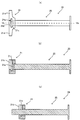
- FIG. 6 (a) is a plan view of the dental viscous material extracting device 1
- FIG. 6 (b) is a sectional view of VIb-VIb of the dental viscous material extracting device 1
- FIG. 6 (c) is a dental viscous material extracting device 1. It is sectional drawing showing other attitude
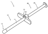
- FIG. 1 is a diagram for explaining one embodiment, and is a perspective view of the dental viscous material extracting device 1
- FIG. 2 is an exploded perspective view of the dental viscous material extracting device 1.
- the dental viscous material extraction device 1 of this embodiment includes a dental viscous material packing body 10 and a pressing tool 20. Each will be described below.
- the dental viscous material package 10 is a container in which a dental viscous material 15 is contained, and includes a container 11, a dental viscous material 15, and an inner plug 16.
- FIG. 3 is a diagram illustrating the dental viscous material package 10. 3A is a plan view, FIG. 3B is a cross-sectional view along IIIb-IIIb, and FIG. 3C is a cross-sectional view along IIIc-IIIc.
- the container 11 is a cylindrical container made of a thermoplastic resin filled with a dental viscous material 15 and having both ends opened. And the outer peripheral part of the cylindrical one end is provided with the protrusion part 12 protruded cyclically
- the protrusion 12 is formed so that the end of the container is wound and curled (see also FIG. 4B). By setting it as such a form, the edge part of a container can be heated and the protrusion part 12 can be formed so that it may mention later.
- thermoplastic resin material which comprises the container 11 is although it does not specifically limit, It is preferable that it is a hard material which has predetermined intensity
- the container 11 is produced by extrusion molding. Thereby, the dental viscous material package 10 can be manufactured easily.
- the thickness of the container 11 is 0.1 mm or more and 0.8 mm or less. Thereby, it can manufacture easily by extrusion molding. It is very difficult to mass produce this thickness by injection molding. Since it is manufactured by extrusion molding, it can be thinned, so that there is an advantage that material can be saved and productivity is high. However, if the thickness of the container is less than 0.1 mm, it is difficult to maintain the cylindrical shape, and there is a possibility of deformation when the dental viscous material is filled. On the other hand, if it exceeds 0.8 mm, the amount of material used increases and the productivity also decreases.
- the dental viscous material 15 is a dental filling material, an artificial tooth material, a crown material preparation material or the like in the dental field.
- a specific example is a paste-like material called a composite resin. This includes a cured resin having a tooth color that hardens when exposed to light, based on a polyfunctional monomer, and filled with a filler such as glass powder or silica powder in a resin (resin).
- the dental viscous material 15 is a highly viscous material.
- the specific viscosity is that having a consistency of 20 mm to 45 mm. If the consistency is less than 20 mm, the material is too hard to be suitable for treatment in the first place. On the other hand, if the consistency exceeds 45 mm, the viscosity is too low to leak out of the dental viscous material package, or it becomes difficult to scrape with a dental tool such as a spatula.
- the consistency is 20 mm or more and 25 mm or less.
- the consistency is defined by the following method. That is, the prepared dental viscous material is vacuum degassed, and then a sample that is allowed to stand at 25 ° C. for 2 hours is used.
- the major axis and the minor axis of the sample after 120 seconds are measured through the glass plate, and the arithmetic average of both is calculated as the consistency.
- the major axis of the sample is the longest of the diameters passing through the center of the sample, and the minor axis of the sample is orthogonal to the major axis of the sample among the diameters passing through the center of the sample.
- Such a dental viscous material 15 is filled in the cylindrical inside of the container 11.
- the inner stopper 16 is disposed at the end of the cylindrical body of the container 11 on the side where the protruding portion 12 is disposed. Accordingly, the dental viscous material 15 is protected and the dental viscous material 15 can be prevented from flowing out of the container 11.
- the dental viscous material package 10 as described above can be manufactured, for example, as follows. First, a cylindrical body that becomes the container 11 and is open at both ends thereof is manufactured by extrusion molding. Then, as shown in FIG. 4A, the material of the container 11 is heated and deformed into the groove 31 of the mold 30 provided with the end portion of the container 11 and the bottom of which has a semicircular groove 31. Push the end of the container 11 while possible. Thus, the projecting portion 12 is formed as shown in FIG. 4B by deforming the end portion so as to be guided and wound along the groove. According to this, a protrusion part can be easily formed, without requiring an additional material.
- the dental viscous material 15 is filled into the inside of the cylindrical body from the opening at one end of both ends that are open. According to such a manufacturing method, the dental viscous material 15 can be filled inside the container 11 without air bubbles being mixed into the dental viscous material. Then, the inner stopper 16 is inserted from the opening of the container 11 on the side where the protruding portion 12 is formed.
- a lid 17 may be provided on the side of the container 11 opposite to the end where the protruding portion 12 is disposed.
- the dental viscous material package 10 As described above, it has a very simple structure, and the amount of waste after use of the dental viscous material can be reduced.
- the pressing tool 20 is an instrument for extracting the dental viscous material 15 from the container 11 of the dental viscous material package 10.
- FIG. 5 shows a diagram for explaining the pressing tool 20.
- 5A is a plan view of the pressing tool 20
- FIG. 5B is a Vb-Vb sectional view
- FIG. 5C is a sectional view showing another posture of the pressing tool 20.
- FIG. 5A is a plan view of the pressing tool 20
- FIG. 5B is a Vb-Vb sectional view
- FIG. 5C is a sectional view showing another posture of the pressing tool 20.
- the pressing tool 20 includes a connecting portion 21 and a pressing portion 25.
- the connection part 21 is a part which connects the dental viscous material packing body 10 and the pressing tool 20, and a groove into which one end of the container 11 is inserted is formed.
- This groove has a connecting groove 21c which is a groove into which the protruding portion 12 is inserted in the container 11, and a groove 21b into which a portion of the container 11 where the protruding portion 12 is not disposed is inserted, and a step is formed here.
- the dental viscous material packing body 10 and the pressing tool 20 are stably connected by the protrusion part 12 of the dental viscous material packing body 10 being caught by this level
- the connecting portion 21 is provided with a hole 21a through which the pressing portion 25 is passed and which leads to the connecting groove 21c.
- a finger hook portion 21d is formed on the connecting portion 21 so as to protrude in a direction away from the groove 21b and the connecting groove 21c. This is a part formed so that the user can put his / her finger.
- the pressing portion 25 is a member that presses the dental viscous material 15 through the inner plug 16 and extracts it from the container 11.
- the pressing part 25 has a rod shape (in this embodiment, a round bar), and one end side thereof is widely formed so as to be easily touched and pressed by a human finger.
- Such a pressing tool 20 is combined by inserting one end of the pressing portion 25 into the hole 21a of the connecting portion 21 (the end portion on the side opposite to the widely formed side). And as shown in FIG.5 (c), the press tool 20 can be moved to the axial direction, and presses the dental viscous material 15 (inner plug 16) by this.
- FIG. 6 shows a diagram for explanation.
- 6 (a) is a plan view of the dental viscous material extracting device 1
- FIG. 6 (b) is a sectional view taken along VIb-VIb
- FIG. 6 (c) is a sectional view showing another posture of the dental viscous material extracting device 1. It is.
- the protruding portion 12 provided on the container 11 of the dental viscous material packing body 10 is inserted into the connecting groove 21c of the pressing tool 20 so as to be inserted. Further, a portion of the container 11 adjacent to the protruding portion 12 is disposed in the groove 21b. Thereby, the pressing tool 20 and the dental viscous material packing body 10 are combined so that the axis of the dental viscous material packing body 10 and the axis of the pressing portion 25 are coaxial. Moreover, since the protrusion part 12 is caught in the level
- the structure is simple and the productivity and the price are excellent.
- the container 11 may be removed from the pressing tool 20 and a new dental viscous material package 10 may be attached to the pressing tool 20.
Landscapes
- Health & Medical Sciences (AREA)
- Oral & Maxillofacial Surgery (AREA)
- Epidemiology (AREA)
- Life Sciences & Earth Sciences (AREA)
- Animal Behavior & Ethology (AREA)
- General Health & Medical Sciences (AREA)
- Public Health (AREA)
- Veterinary Medicine (AREA)
- Dentistry (AREA)
- Dental Tools And Instruments Or Auxiliary Dental Instruments (AREA)
Abstract
安価で構造が簡易な歯科用粘性材料梱包体を提供するため、歯科用粘性材料梱包体は、厚さが0.1mm以上0.8mm以下の筒状であり、その一端側の外周に突出部(12)が設けられた熱可塑性樹脂製の容器(11)と、容器の内側に充填され、稠度が20mm以上45mm以下である歯科用粘性材料(15)と、容器内に配置される中栓(16)と、を備える。
Description
本発明は、歯科用粘性材料が容器に充填された歯科用粘性材料梱包体、及びこれを備える歯科用粘性材料抽出器具に関する。
歯科分野において歯科用充填材料、人工歯用材料、及び歯冠材作製用材料等の歯科用粘性材料を取り扱う場合、粘性の高い歯科用粘性材料が筒状の使い捨て容器に充填された態様(歯科用粘性材料梱包体)で提供されることが多い。
一般的な歯科用粘性材料梱包体の構造及びその使用態様が、例えば特許文献1~4に開示されている。すなわち、歯科用粘性材料を収納する筒状の部材(例えばシリンジ)の一方の端部から押圧部材(例えばネジで繰り出すピストン)を挿入して筒状の部材の他方の端部から歯科用粘性材料を少量流出させる。そして、流出した歯科用粘性材料を先端が球体やヘラ状等の形状のステッィク状の歯科用工具で掻き取り、修復しようとする歯牙や作製しようとする歯科用部材の表面へ適用する。
これら特許文献に記載の技術では、歯科用粘性材料の抽出に関するそれぞれの効果を有するものの、いずれもその構造は複雑で大きなものとなる傾向にあった。さらにそのための容器は、射出成形で製造されるために、生産性、価格の観点からも問題があった。
そこで本発明は、安価で構造が簡易な歯科用粘性材料梱包体を提供することを課題とする。また、これを具備する歯科用粘性材料抽出器具を提供する。
以下、本発明について説明する。ここでは分かり易さのため、図面に付した参照符号を括弧書きで併せて記載するが、本発明はこれに限定されるものではない。
本発明の1つの態様は、厚さが0.1mm以上0.8mm以下の筒状であり、その一端側の外周に突出部(12)が設けられた熱可塑性樹脂製の容器(11)と、容器の内側に充填され、稠度が20mm以上45mm以下である歯科用粘性材料(15)と、容器内に配置される中栓(16)と、を備える、歯科用粘性材料梱包体(10)である。
また、上記歯科用粘性材料梱包体(10)と、歯科用粘性材料梱包体を着脱可能とする押圧具(20)と、を有し、押圧具は、容器(11)の突出部(12)が挿入される溝(21c)を具備する連結部(21)と、容器の内側に挿入可能な棒状の押圧部(25)と、を備える、歯科用粘性材料抽出器具(1)を提供できる。
本発明によれば、非常に簡易な構造の歯科用粘性材料梱包体となり、押し出し成形により製造することが可能な構造であるため、射出成形と比較して非常に安価に製造をすることができる。
また、この歯科用粘性材料梱包体を備える歯科用粘性材料抽出器具を提供した際には、歯科用粘性材料の使用後には歯科用粘性材料梱包体のみを新しいものに取り換えればよい。
また、この歯科用粘性材料梱包体を備える歯科用粘性材料抽出器具を提供した際には、歯科用粘性材料の使用後には歯科用粘性材料梱包体のみを新しいものに取り換えればよい。
以下、本発明を図面に示す形態に基づき説明する。ただし本発明はこれら形態に限定されるものではない。
図1は1つの形態を説明する図であり、歯科用粘性材料抽出器具1の斜視図、図2は歯科用粘性材料抽出器具1の分解斜視図である。図1、図2よりわかるように本形態の歯科用粘性材料抽出器具1は、歯科用粘性材料梱包体10、及び押圧具20を有して構成されている。以下、それぞれについて説明する。
歯科用粘性材料梱包体10は、歯科用粘性材料15が内包された容器であり、容器11、歯科用粘性材料15、及び中栓16を有して構成されている。図3には歯科用粘性材料梱包体10を説明する図を示した。図3(a)は平面図、図3(b)はIIIb-IIIb断面図、図3(c)はIIIc-IIIc断面図である。
容器11は、歯科用粘性材料15が充填され、両端が開放された熱可塑性樹脂からなる筒状の容器である。そして、筒状の一端の外周部には、環状に突出した突出部12を備えている。後述するようにこの突出部12が押圧具20の連結溝21cに差し込まれることにより歯科用粘性材料梱包体10が押圧具20に連結される。
本形態で突出部12は図3(c)からわかるように、容器の端部が巻かれてカールするように形成されている(図4(b)も参照。)。このような形態とすることで、後述するように、容器の端部を加熱して突出部12を形成することができる。
本形態で突出部12は図3(c)からわかるように、容器の端部が巻かれてカールするように形成されている(図4(b)も参照。)。このような形態とすることで、後述するように、容器の端部を加熱して突出部12を形成することができる。
また、容器11を構成する熱可塑性樹脂材料は特に限定されることはないが、所定の強度を有する硬い材料であることが好ましい。具体的には、ポリエチレン樹脂、ポリアセタール樹脂、ポリプロピレン樹脂、ポリアミド樹脂、塩化ビニル樹脂、ナイロン樹脂、フェノール樹脂、ポリウレタン樹脂、飽和ポリエステル樹脂、メラミン樹脂 、ポリ塩化ビニリデン樹脂、不飽和ポリエステル樹脂、ポリブタジエン樹脂、ポリスチレン樹脂、EVA(エチレン-酢酸ビニル共重合)樹脂、スチロール樹脂、ポリメチルペンテン樹脂、メタクリルスチレン樹脂、ABS(アクロル二トリル、ブタジエン、スチレン)樹脂、ポリカーボネート樹脂等を好ましく使用できる。
そして容器11は押し出し成形にて作製されている。これにより容易に歯科用粘性材料梱包体10を製造することができる。
そして容器11は押し出し成形にて作製されている。これにより容易に歯科用粘性材料梱包体10を製造することができる。
容器11の厚さは0.1mm以上0.8mm以下である。これにより押し出し成形にて容易に製造することができる。射出成形でこの厚さを量産することは非常に困難である。押し出し成形にて作製されているため、薄くすることができることから材料も節約でき、且つ生産性が高い利点がある。ただし、容器の厚さが0.1mm未満では筒状を維持することが難しく歯科用粘性材料を充填した際に変形する虞もある。一方、0.8mmを越えると材料の使用量が増え生産性も低下する。
歯科用粘性材料15は、歯科分野において歯科用充填材料、人工歯用材料、及び歯冠材作製用材料等である。具体的な例としては、コンポジットレジンと呼ばれているペースト状の材料である。これには、光を当てると固まる歯の色をした硬化樹脂であって、多官能モノマーをベースとし、レジン(樹脂)中にガラス粉末やシリカ粉末などのフィラーを充填したものが挙げられる。
歯科用粘性材料15は、この中でも粘性の高い材料である。具体的な粘性は、稠度が20mm以上45mm以下とされているものである。稠度が20mm未満では材料が硬すぎてそもそも治療に適さない。一方で稠度が45mmを越えると粘性が低すぎて歯科用粘性材料梱包体から漏れ出てしまったり、ヘラ等の歯科用工具で掻き取って使用することが難しくなったりする。好ましくは、稠度が20mm以上25mm以下である。
ここで稠度は、以下の方法で定義される。すなわち、調製した歯科用粘性材料を真空脱泡後、25℃に2時間静置した試料を使用する。0.5mLの試料を量り取り、25℃の恒温室内(湿度40%)でガラス板(5cm×5cm)の中心に盛り上げるように静置させ、その上に40gのガラス板(5cm×5cm)を載せ、120秒経過後の試料の長径と短径をガラス板越しに測定し、その両者の算術平均を算出したものを稠度とする。なお、試料の長径は、試料の中心を通る直径のうち最も長いもの、試料の短径は、試料の中心を通る直径のうち試料の長径に直交するものとする。
ここで稠度は、以下の方法で定義される。すなわち、調製した歯科用粘性材料を真空脱泡後、25℃に2時間静置した試料を使用する。0.5mLの試料を量り取り、25℃の恒温室内(湿度40%)でガラス板(5cm×5cm)の中心に盛り上げるように静置させ、その上に40gのガラス板(5cm×5cm)を載せ、120秒経過後の試料の長径と短径をガラス板越しに測定し、その両者の算術平均を算出したものを稠度とする。なお、試料の長径は、試料の中心を通る直径のうち最も長いもの、試料の短径は、試料の中心を通る直径のうち試料の長径に直交するものとする。
このような歯科用粘性材料15が容器11の筒状である内側に充填されている。
中栓16は、容器11の筒状体の内側のうち、突出部12が配置された側の端部に配置されている。これにより、歯科用粘性材料15が保護されるとともに、歯科用粘性材料15が容器11から流出することを防止することができる。
以上のような歯科用粘性材料梱包体10は、例えば次のように製造することができる。
初めに、容器11となる筒状体で、その両端が開口している筒状体を押し出し成形により作製する。そして、図4(a)に示したように、容器11の端部が挿入され、その底が半円形を有する溝31を備える型30の当該溝31に、容器11の材料を加熱して変形可能なうちに容器11の端部を押し付ける。これにより、当該端部を溝に沿って誘導して巻くようにしてカールさせる変形をして図4(b)のように突出部12を形成する。これによれば追加の材料を必要とせずに容易に突出部を形成することができる。
次に開口している両端の一方の端部の開口から歯科用粘性材料15を筒状体の内側に充填する。
このような製造方法によれば歯科用粘性材料に気泡が混入することなく容器11の内側に歯科用粘性材料15を充填することができる。そして突出部12が形成された側の容器11の開口から中栓16を挿入する。
初めに、容器11となる筒状体で、その両端が開口している筒状体を押し出し成形により作製する。そして、図4(a)に示したように、容器11の端部が挿入され、その底が半円形を有する溝31を備える型30の当該溝31に、容器11の材料を加熱して変形可能なうちに容器11の端部を押し付ける。これにより、当該端部を溝に沿って誘導して巻くようにしてカールさせる変形をして図4(b)のように突出部12を形成する。これによれば追加の材料を必要とせずに容易に突出部を形成することができる。
次に開口している両端の一方の端部の開口から歯科用粘性材料15を筒状体の内側に充填する。
このような製造方法によれば歯科用粘性材料に気泡が混入することなく容器11の内側に歯科用粘性材料15を充填することができる。そして突出部12が形成された側の容器11の開口から中栓16を挿入する。
また、図1、図2に示したように、容器11の突出部12が配置された端部とは反対側にはフタ17が備えられてもよい。
以上のような歯科用粘性材料梱包体10によれば、非常に簡易な構造であり、歯科用粘性材料の使用後における廃棄物の量を減らすこともできる。
図1、図2に戻って押圧具20について説明する。押圧具20は、歯科用粘性材料梱包体10の容器11から歯科用粘性材料15を抽出する器具である。図5に押圧具20を説明するための図を示した。図5(a)は押圧具20の平面図、図5(b)はVb-Vb断面図、図5(c)は押圧具20の他の姿勢を表す断面図である。
図1、図2、及び図5よりわかるように、押圧具20は連結部21及び押圧部25を有して構成されている。
連結部21は、歯科用粘性材料梱包体10と押圧具20とを連結する部位であり、容器11の一端が差し込まれる溝が形成されている。この溝は容器11のうち突出部12が差し込まれる溝である連結溝21cと容器11のうち突出部12が配置されていない部位が差し込まれる溝21bとを有しており、ここに段差が形成されている。そして、この段差に歯科用粘性材料梱包体10の突出部12が引っ掛かることにより安定して歯科用粘性材料梱包体10と押圧具20とが連結される。
また連結部21には、押圧部25が通され、連結溝21cに通じる穴21aが設けられている。
また連結部21には、押圧部25が通され、連結溝21cに通じる穴21aが設けられている。
さらに、連結部21には溝21b、連結溝21cから離隔する方向に張り出すようにして指掛け部21dが形成されている。これは使用者が指を掛けることができるように形成された部位である。
押圧部25は、中栓16を介して歯科用粘性材料15を押圧し、これを容器11から抽出する部材である。押圧部25は棒状(本形態では丸棒)であり、その一端側は、人の指が触れて押圧しやすいように広く形成されている。
このような押圧具20は、連結部21の穴21aに押圧部25の一端(広く形成された側とは反対側の端部)が差し込まれることにより組み合わされている。そして、図5(c)に示したように、押圧具20はその軸線方向に移動させることができ、これにより歯科用粘性材料15(中栓16)を押圧する。
以上説明した歯科用粘性材料抽出器具1は例えば次のように用いられる。図6に説明のための図を示した。図6(a)は歯科用粘性材料抽出器具1の平面図、図6(b)はVIb-VIb断面図、図6(c)は歯科用粘性材料抽出器具1の他の姿勢を表す断面図である。
図6(a)、図6(b)からわかるように、押圧具20の連結溝21cに歯科用粘性材料梱包体10の容器11に設けられた突出部12を挿入するように配置する。また溝21bには容器11のうち突出部12に隣接した部位が配置される。これにより歯科用粘性材料梱包体10の軸線と押圧部25の軸線とが同軸となるように押圧具20と歯科用粘性材料梱包体10とが組み合わされる。また、溝21bと連結溝21cとの段差に突出部12が引っ掛かるので歯科用粘性材料梱包体10と押圧具20とが安定して連結される。
このような姿勢から、図6(c)に示したように、押圧部25を押圧して移動させると、これにより歯科用粘性材料梱包体10の歯科用粘性材料15が中栓16を介して押圧され、該歯科用粘性材料15が容器11の一端から押し出されて突出する。そしてこのように飛び出した歯科用粘性材料15を施術者が歯科用工具で取り、修復しようとする歯牙や作製しようとする歯科用材料の表面へ適用する。
以上のような歯科用粘性材料梱包体10、及びこれを備える歯科用粘性材料抽出器具1によれば、構造が簡易であり、生産性や価格において優れたものとなる。
また、歯科用粘性材料15が使い終わった後は、容器11を押圧具20から取り外して新しい歯科用粘性材料梱包体10を押圧具20に装着すればよい。
1 歯科用粘性材料抽出器具
10 歯科用粘性材料梱包体
11 容器
12 突出部
15 歯科用粘性材料
16 中栓
17 フタ
20 押圧具
21 連結部21
21a 穴
21b 溝
21c 連結溝
25 押圧部
10 歯科用粘性材料梱包体
11 容器
12 突出部
15 歯科用粘性材料
16 中栓
17 フタ
20 押圧具
21 連結部21
21a 穴
21b 溝
21c 連結溝
25 押圧部
Claims (2)
- 厚さが0.1mm以上0.8mm以下の筒状であり、その一端側の外周に突出部が設けられた熱可塑性樹脂製の容器と、
前記容器の内側に充填され、稠度が20mm以上45mm以下である歯科用粘性材料と、
前記容器内に配置された中栓と、を備える、歯科用粘性材料梱包体。 - 請求項1に記載の歯科用粘性材料梱包体と、
前記歯科用粘性材料梱包体を着脱可能とする押圧具と、を有し、
前記押圧具は、
前記容器の突出部が挿入される溝を具備する連結部と、
前記容器の内側に挿入可能な棒状の押圧部と、を備える、歯科用粘性材料抽出器具。
Applications Claiming Priority (2)
| Application Number | Priority Date | Filing Date | Title |
|---|---|---|---|
| JP2016186917 | 2016-09-26 | ||
| JP2016-186917 | 2016-09-26 |
Publications (1)
| Publication Number | Publication Date |
|---|---|
| WO2018055876A1 true WO2018055876A1 (ja) | 2018-03-29 |
Family
ID=61690266
Family Applications (1)
| Application Number | Title | Priority Date | Filing Date |
|---|---|---|---|
| PCT/JP2017/024993 Ceased WO2018055876A1 (ja) | 2016-09-26 | 2017-07-07 | 歯科用粘性材料梱包体、歯科用粘性材料抽出器具 |
Country Status (1)
| Country | Link |
|---|---|
| WO (1) | WO2018055876A1 (ja) |
Citations (3)
| Publication number | Priority date | Publication date | Assignee | Title |
|---|---|---|---|---|
| JPH02228958A (ja) * | 1989-02-06 | 1990-09-11 | William B Dragan | 歯科用注射器チツプ |
| WO2008093596A1 (ja) * | 2007-02-01 | 2008-08-07 | Kuraray Medical Inc. | 歯科用硬化性組成物 |
| WO2011132714A1 (ja) * | 2010-04-22 | 2011-10-27 | 株式会社トクヤマデンタル | 吐出器具及び吐出器具の充填材料の充填方法 |
-
2017
- 2017-07-07 WO PCT/JP2017/024993 patent/WO2018055876A1/ja not_active Ceased
Patent Citations (3)
| Publication number | Priority date | Publication date | Assignee | Title |
|---|---|---|---|---|
| JPH02228958A (ja) * | 1989-02-06 | 1990-09-11 | William B Dragan | 歯科用注射器チツプ |
| WO2008093596A1 (ja) * | 2007-02-01 | 2008-08-07 | Kuraray Medical Inc. | 歯科用硬化性組成物 |
| WO2011132714A1 (ja) * | 2010-04-22 | 2011-10-27 | 株式会社トクヤマデンタル | 吐出器具及び吐出器具の充填材料の充填方法 |
Similar Documents
| Publication | Publication Date | Title |
|---|---|---|
| JP5985061B2 (ja) | 自動充填及び定量吐出スポイト型容器キャップ | |
| US6805510B2 (en) | Cosmetic powder applicator and method for making and using the same | |
| KR20090008046U (ko) | 수동식 드롭퍼 | |
| KR200469855Y1 (ko) | 스포이드 결합형 분말 혼합 화장용기 | |
| US20190001368A1 (en) | Device for applying adhesive and/or Sealant | |
| JP2022044748A (ja) | 薬液注入装置およびその装置に使用される注射針 | |
| JP6522283B2 (ja) | 粘着体の付与方法及び便器用器具 | |
| US20150209228A1 (en) | Squeezable Ampule with Breakable Seal in Nose Bleed Kit | |
| CN106659281A (zh) | 化妆品,特别是睫毛膏用涂敷器、涂敷器和产品容器的组合件、制造涂敷器的方法和装置 | |
| JP3197535U (ja) | 管詰め接着剤の押出装置 | |
| US20150209191A1 (en) | Nose bleed kit | |
| WO2007094243A1 (ja) | 容器 | |
| KR101810811B1 (ko) | 화장품 용기 | |
| JP2004154557A (ja) | 2つの受け器を一体化できる結合部材を備えた包装兼塗布器具 | |
| JP4679980B2 (ja) | 塗布具 | |
| JP2014226325A (ja) | 塗布具のしごき機能を有する中栓 | |
| JP2018000455A (ja) | 歯科用粘性材料梱包体 | |
| KR20210000216U (ko) | 스포이드형 앰플용기 | |
| JP3126314U (ja) | 注射器型玩具 | |
| JPH038296Y2 (ja) | ||
| US9949499B2 (en) | Handheld concealed pill morsel former | |
| CN203814368U (zh) | 一种能释放微胶囊的梳子 | |
| KR200429812Y1 (ko) | 그림물감 주사기 | |
| CN207329197U (zh) | 接着固定密封剂器具改良结构 | |
| CN207417196U (zh) | 一种推注式精油加注器 |
Legal Events
| Date | Code | Title | Description |
|---|---|---|---|
| 121 | Ep: the epo has been informed by wipo that ep was designated in this application |
Ref document number: 17852657 Country of ref document: EP Kind code of ref document: A1 |
|
| NENP | Non-entry into the national phase |
Ref country code: DE |
|
| 122 | Ep: pct application non-entry in european phase |
Ref document number: 17852657 Country of ref document: EP Kind code of ref document: A1 |
|
| NENP | Non-entry into the national phase |
Ref country code: JP |