WO2018055809A1 - 車両の組立ライン - Google Patents
車両の組立ライン Download PDFInfo
- Publication number
- WO2018055809A1 WO2018055809A1 PCT/JP2017/010710 JP2017010710W WO2018055809A1 WO 2018055809 A1 WO2018055809 A1 WO 2018055809A1 JP 2017010710 W JP2017010710 W JP 2017010710W WO 2018055809 A1 WO2018055809 A1 WO 2018055809A1
- Authority
- WO
- WIPO (PCT)
- Prior art keywords
- vehicle body
- assembly line
- line
- work area
- vehicle
- Prior art date
- Legal status (The legal status is an assumption and is not a legal conclusion. Google has not performed a legal analysis and makes no representation as to the accuracy of the status listed.)
- Ceased
Links
Images




Classifications
-
- B—PERFORMING OPERATIONS; TRANSPORTING
- B62—LAND VEHICLES FOR TRAVELLING OTHERWISE THAN ON RAILS
- B62D—MOTOR VEHICLES; TRAILERS
- B62D65/00—Designing, manufacturing, e.g. assembling, facilitating disassembly, or structurally modifying motor vehicles or trailers, not otherwise provided for
- B62D65/02—Joining sub-units or components to, or positioning sub-units or components with respect to, body shell or other sub-units or components
- B62D65/10—Joining sub-units or components to, or positioning sub-units or components with respect to, body shell or other sub-units or components the sub-units or components being engines, clutches or transmissions
-
- B—PERFORMING OPERATIONS; TRANSPORTING
- B62—LAND VEHICLES FOR TRAVELLING OTHERWISE THAN ON RAILS
- B62D—MOTOR VEHICLES; TRAILERS
- B62D65/00—Designing, manufacturing, e.g. assembling, facilitating disassembly, or structurally modifying motor vehicles or trailers, not otherwise provided for
- B62D65/02—Joining sub-units or components to, or positioning sub-units or components with respect to, body shell or other sub-units or components
- B62D65/12—Joining sub-units or components to, or positioning sub-units or components with respect to, body shell or other sub-units or components the sub-units or components being suspensions, brakes or wheel units
-
- B—PERFORMING OPERATIONS; TRANSPORTING
- B62—LAND VEHICLES FOR TRAVELLING OTHERWISE THAN ON RAILS
- B62D—MOTOR VEHICLES; TRAILERS
- B62D65/00—Designing, manufacturing, e.g. assembling, facilitating disassembly, or structurally modifying motor vehicles or trailers, not otherwise provided for
- B62D65/02—Joining sub-units or components to, or positioning sub-units or components with respect to, body shell or other sub-units or components
- B62D65/18—Transportation, conveyor or haulage systems specially adapted for motor vehicle or trailer assembly lines
Definitions
- the present disclosure relates to a vehicle assembly line, and more particularly to a vehicle underbody assembly line.
- Patent Document 1 discloses an assembly line of a vehicle provided with a plurality of transport devices for moving a floor surface while supporting a vehicle body and transporting the vehicle body along an assembly line.
- Each of the plurality of transport devices has a support portion for supporting the vehicle body in a posture in which the longitudinal direction of the vehicle body is orthogonal to the line traveling direction of the assembly line of the vehicle body, and a base for fixing the support portion on the upper surface There is.
- the support portion has an upstream side support portion and a downstream side support portion arranged in line symmetry on a base centering on a center line extending in a direction orthogonal to the line traveling direction of the assembly line.
- the transfer of a tool for transferring a tool used when assembling an undercarriage component to the vehicle body in communication along the line traveling direction of the assembly line A passage is formed. Further, below the vehicle body supported by the transfer device, a component space for disposing an undercarriage component is formed independently of the transfer passage.
- a component mounting carriage between the lower upstream support and the lower downstream support of the vehicle body.
- a transfer passage is formed below the front side portion of the vehicle body and below the rear side portion of the vehicle body, and this transfer passage can be used as a tool transfer space for mounting components.
- bogie which mounted the attachment components can be arrange
- the conventional vehicle assembly line described in Patent Document 1 supports the vehicle body in a direction substantially orthogonal to the line traveling direction, so the front and rear sides of the vehicle body are from the assembly line It is in the state of being projected. For this reason, arrangement
- this lifting device large parts such as the front and rear suspensions and the engine and transmission can be easily carried in and arranged on the front and rear sides of the vehicle body.
- the assembly line of this conventional vehicle is narrow because the width between each of the support of the upstream side support and the downstream side support that supports the vehicle body is about the same as the vehicle width. For this reason, large parts such as under-floor piping, fuel tanks, and mufflers are carried into the lower part of the vehicle body from the front-rear direction of the vehicle body via the space between the upstream support and the downstream support below the vehicle. troublesome. Therefore, there is a possibility that the efficiency of the assembling work of the parts to the lower part of the vehicle body may be reduced.
- At least one embodiment of the present invention is an invention made on the basis of the state of the prior art as described above, and an object thereof is to improve the efficiency of the work of assembling parts to the lower part of the vehicle body. Aims to provide a vehicle assembly line that can
- a vehicle assembly line includes a plurality of transport devices for transporting the vehicle body along the assembly line while supporting the vehicle body, and the vehicle body supported by the transport device It is an assembly line of a vehicle in which parts are assembled in the lower part, and the transfer device includes a base movable in a line traveling direction of the assembly line, a rotary table provided on the upper surface of the base, and the rotary table And a support portion extending upward and in contact with a lower portion of the vehicle body to support the vehicle body, wherein the rotating table is formed in a circular shape in plan view with respect to the upper surface of the rotating table
- the base is provided with a pivot mechanism portion for pivoting the rotary table, and the support portion is provided in the diameter direction of the upper surface of the rotary table.
- the support portion supports the vehicle body in a state in which the extending direction of the beam portion is along the longitudinal direction of the vehicle body, and the assembly line
- the rotary table is rotated from the first work area where component assembly work is performed in a state in which the longitudinal direction of the vehicle body is along the line advancing direction of the assembly line, and the position of the rotary table in the first work area.
- the support portion supports the vehicle body in a state in which the extending direction of the beam portion is along the front-rear direction of the vehicle body. For this reason, in the first work area, the vehicle body is supported by the support portion in a state in which the front-rear direction of the vehicle body is along the line traveling direction of the assembly line. Spaces are formed on the front and rear sides in the vehicle longitudinal direction with respect to the support column of the support. Therefore, when the component shelf is installed on one side of the assembly line along the line traveling direction, when the transport device moves to the first work area, the component taken out of the component shelf is taken from the front and back of the support in the vehicle longitudinal direction. It can be easily carried in and assembled to the front side or the rear side of the vehicle body via the space formed on the side.
- the transport device is provided with the rotating table and the turning mechanism portion, the longitudinal direction of the vehicle body can be made to be in the direction crossing the line advancing direction. Therefore, in the second work area, the front-rear direction of the vehicle body is in the state of crossing the line travel direction, so that the respective end portions in the front-rear direction of the vehicle body are orthogonal to the travel direction of the assembly line It can be made to project to the outside of the direction of movement. Therefore, when a lifting device such as a mounted lifter is disposed on the floor adjacent to the assembly line, the lifting device moves components such as the front and rear suspensions and the engine and transmission to the front and rear of the vehicle body. Easy to carry in and assemble.
- the beam portions of the pair of support portions are disposed in parallel in plan view, and the beam portions of the pair of support portions are Each support column portion is configured to be fixed on the rotary table in a state in which it faces in a direction inclined with respect to the extension direction of the beam portion provided on the support column portion in a plan view.
- the support post portion is fixed on the rotary table in a state in which the support post portion faces a direction inclined with respect to the extension direction of the beam portion provided on the support post portion in plan view.
- one of the pair of support portions is a portion between the pair of receiving portions provided on the one support portion. Is smaller than the distance between the pair of receivers provided on the other support.
- the distance between the pair of receiving portions provided in one of the support portions is provided in the other support portion. It is smaller than the distance between the pair of receivers. For this reason, the area of the space under the vehicle body on the front side and the rear side of the line advancing direction of one support portion can be made larger than the area of the corresponding space of the other support portion.
- components are carried in from the side on which the one support portion is provided in the both sides of the assembly line, so the lower part of the vehicle body
- the area of the space can be made larger than the area of the corresponding space of the other support and the parts of the vehicle can be easily transported to the area of the space under the vehicle body.
- the front portion of the vehicle body is in contact with the pair of receiving portions provided on the one supporting portion.
- the support portion to be supported is disposed such that the distance between the support portion and the support portion in plan view is larger than the distance between the support portion that abuts and supports the rear side portion of the vehicle body and the support portion.
- the receiving portion for supporting the front side portion of the vehicle body in contact with and supporting the rear side portion of the vehicle body in the distance between the receiving portion and the column portion in plan view By making the distance between the receiving portion and the support portion larger, it is possible to suppress an increase in the moment acting on the receiving portion that supports the front side of the vehicle body, and stably support the front side of the vehicle body.
- the component assembled to the lower portion of the vehicle body in the first work area is an insulator, It is an undercarriage including at least one of a brace and a cable.
- the component assembled to the lower portion of the vehicle body in the first work area is an undercarriage component including at least one of an insulator, a brace, and a cable.
- the vehicle body is supported by the support portion in a state in which the front-rear direction of the vehicle body is along the line advancing direction of the assembly line. Space is formed. Therefore, the underbody component including at least one of the insulator, the brace, and the cable can be assembled to the lower portion of the vehicle body through these spaces.
- the part assembled to the lower portion of the vehicle body in the second work area is a front drive unit Or it is a rear drive unit.
- the component assembled to the lower part of the vehicle body in the second work area is the front drive unit or the rear drive unit.
- a lifting device such as a loading lifter can be disposed on the floor adjacent to the assembly line, so that the front drive unit or the rear drive unit can be easily carried in and assembled on the front and rear sides of the vehicle body by this lifting device. it can.
- the assembly line is the line extending direction from one end side to the other end side.
- the first assembly line is provided with a first work area on the upstream side, and is provided with a second work area on the downstream side, and the second assembly line is provided with a second work area on the upstream side, and downstream There is a first work area on the side
- the line connection portion is configured to be capable of moving the transfer device while maintaining the orientation of the base of the transfer device and the vehicle body in a second work area of the first assembly line, the transfer device being When the base moves between the first work area and the second work area of the first
- the rotary table is configured to rotate so as to be in a direction along.
- the first assembly line and the second assembly line are connected via the line connection portion, and the line connection portion is connected to the vehicle body in the second work area of the first assembly line.
- the transport device is configured to be movable while maintaining the orientation. For this reason, the vehicle body supported by the support portion of the transfer device is transferred from the second work area of the first assembly line to the second work area of the second assembly line while maintaining the same direction. Therefore, when a lifting device capable of lifting and lowering parts is installed on the right side in the line traveling direction of each of the first assembly line and the second assembly line, the lifting devices can easily carry heavy components to the front and rear sides of the vehicle. Can be arranged.
- the line connection portion is a line connecting the first assembly line and the second assembly line
- the first assembly line and the second assembly line are disposed adjacent to each other, thus shortening the path of the line connection portion. can do. Therefore, the path between the second work areas of the first assembly line and the second assembly line can be shortened.
- FIGS. 1 to 8 an embodiment of a vehicle assembly line of the present invention will be described with reference to FIGS. 1 to 8 according to the attached drawings.
- the dimensions of the component parts described in the embodiment or shown in the drawings, the quality, the shape, the relative arrangement, etc. of the components are not intended to limit the scope of the present invention to this, but are merely illustrative. Only.
- a representation representing a relative or absolute arrangement such as “in a direction”, “along a direction”, “parallel”, “orthogonal”, “center”, “concentric” or “coaxial” is strictly Not only does it represent such an arrangement, but also represents a state of relative displacement with an angle or distance that allows the same function to be obtained.
- expressions that indicate that things such as “identical”, “equal” and “homogeneous” are equal states not only represent strictly equal states, but also have tolerances or differences with which the same function can be obtained. It also represents the existing state.
- expressions representing shapes such as quadrilateral shapes and cylindrical shapes not only represent shapes such as rectangular shapes and cylindrical shapes in a geometrically strict sense, but also uneven portions and chamfers within the range where the same effect can be obtained. The shape including a part etc. shall also be expressed.
- the expressions “comprising”, “having”, “having”, “including” or “having” one component are not exclusive expressions excluding the presence of other components.
- symbol may be attached
- FIG. 1 is an overall plan view of an assembly line of a vehicle according to an embodiment of the present invention.
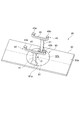
- FIG. 2 is a perspective view of the transfer device.
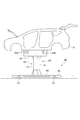
- FIG. 3 is a side view of the transfer device for supporting the vehicle body.
- FIG. 4 is a front view of a transfer device for supporting a vehicle body.
- FIG. 5 shows a pivoting mechanism provided in the transport apparatus, and FIG. 5 (a) is a plan view of the pivoting mechanism, and FIG. 5 (b) is a side view of the pivoting mechanism.
- the same figure (c) is a front view of a rotation mechanism part.
- an assembly line of a vehicle for assembling parts to a lower portion of a vehicle body will be described.
- the assembly line 1 of the vehicle is, as shown in FIG. 1, FIG. 2 and FIG. 3, a conveyance for conveying the vehicle body 3 along the assembly line 10, 10 'in a state of supporting the vehicle body 3.
- a vehicle assembly line 1 including a plurality of devices 20 and assembling parts to a lower portion of a vehicle body 3 supported by a transport device 20, wherein the transport device 20 is arranged along a rail R disposed on a floor surface Fs.
- the rotary base 61 is formed in a circular shape in a plan view and provided rotatably around a central axis extending in a direction orthogonal to the upper surface 61 a of the rotary base 61.
- the table 50 is provided with a rotating mechanism 60 for rotating the rotating table 61
- the supporting portions 40 are provided at both ends in the diameter direction of the upper surface 61a of the rotating table 61, fixed to the upper surface 61a of the rotating table 61 and attached to the upper end of the supporting column 41
- the supporting portion 40 includes a beam portion 45 extending horizontally on both sides with the support portion 41 at the center, and a receiving portion 43 provided at both end portions in the extending direction of the beam portion 45 for abuttingly supporting the vehicle body 3;
- the vehicle body 3 is supported in a state in which the extending direction of the beam portion 45 is along the front-rear direction of the vehicle body 3, and the assembly line 1 is assembled
- a second working area A2 in which component assembling work is performed in a state in which the longitudinal direction of the vehicle body 3 is directed to a direction intersecting the line advancing direction
- a rotation mechanism 60 Is the first work area A1 and the second work Configured to rotate the turntable 61 so that the orientation of the
- the upstream assembly line 10 is provided with a first work area A1 on the upstream side in the line traveling direction, and a second work area A2 on the downstream side of the first work area A1. It is provided. Further, on the upstream side of the first work area A1, a vehicle carry-in area Ai in which the vehicle body 3 is carried into the assembly line 10 and the direction is rotated is provided.
- the downstream assembly line 10' is provided with a second work area A2 on the upstream side in the line traveling direction and a first work area A1 on the downstream side. There is. Further, on the downstream side of the first work area A1, a vehicle carry-out area Ao is provided to carry out the vehicle body 3 from the assembly line 10 'by changing the direction of the vehicle body 3.
- two rails R are juxtaposed on the floor surface Fs in each of the assembly lines 10 and 10 ', and the rails R are used to transport the transport device 20.
- a large number of driven rods 70 are rotatably provided.
- the conveyance drive part which is not shown in figure which contact
- the base 50 is provided with a hole 50 b at the center of the upper surface 50 a.
- a rotary base 61 is provided in the hole 50b.
- the rotary table 61 is rotatably supported around a central axis extending in a direction orthogonal to the rotary table 61.
- the upper surface 61 a of the rotating table 61 is disposed on substantially the same plane as the upper surface 50 a of the base 50.
- the rotation mechanism 60 has a rotation drive 63 provided on the lower surface 61b of the rotation table 61 and rotation of the rotation table 61. And a rotation restricting portion 65 for locking movement.
- the rotation drive unit 63 includes a worm wheel 63a provided on the lower surface 61b of the rotary base 61, a worm gear 63b meshing with the worm wheel 63a, and an electric motor 63c for rotationally driving the worm gear 63b.
- the rotation center of the worm wheel 63 a is disposed coaxially with the rotation center O of the rotating table 61.
- the worm gear 63b is fixed to a rotation shaft 63c1 of the electric motor 63c.
- the electric motor 63c is a rotation area for rotating the vehicle body 3 of the assembly lines 10 and 10 'described above, ie, an area A4 between the second operation area A2 of the assembly line 10 on the upstream side and the first operation area A1.
- An area A4 between the second work area A2 and the first work area A1 of the downstream assembly line 10 ', a vehicle loading area Ai, and a vehicle unloading area Ao are provided.
- the electric motor 63c moves between a separation position at which the worm gear 63b separates from the worm wheel 63a when the transport device 20 moves to the area for rotating the vehicle body 3, and a meshing position at which the worm gear 63b meshes with the worm wheel 63a. It is configured to be possible. As described above, by arranging the electric motor 63c only in the area where the conveyance device 20 rotates the vehicle body 3, the cost can be reduced and the electric motor 63c can be reduced compared to the case where the electric motor 63c is provided for each conveyance device 20. It is possible to simplify the routing of the connected wires.
- the rotation restricting portion 65 can move a plurality of protrusions 66 provided on the lower surface 61 b of the rotary table 61 and a locking protrusion 67 engageable with an engagement hole 66 a formed in the protrusion 66.
- a drive cylinder 68 for supporting the The protrusions 66 are provided on the lower surface 61 b of the rotary table 61 at equal intervals in the circumferential direction. In the illustrated embodiment, three protrusions 66 are provided at an angle of 90 ° in the circumferential direction.
- the drive source of the drive cylinder 68 may be air, hydraulic pressure or the like.
- the respective beam portions 45 of the pair of support portions 40 are disposed in parallel in plan view, and the respective support portions 41 of the pair of support portions 40 are in plan view It is configured to be fixed on the upper surface 61 a of the rotating table 61 in a state in which it is directed in a direction inclined with respect to the extension direction of the beam portion 45 provided in the support portion 41. That is, the cross-sectional shape of the support column 41 in a plan view has a rectangular shape, and the center line of the cross-sectional shape is inclined to the center line of the beam 45 in the extending direction. In the present embodiment, the support portion 41 is fixed on the rotating table 61.
- each of the pair of support portions 41 are disposed to face each other toward the rotation center O of the rotation table 61.
- the center line of the support column 41 is inclined at an angle ⁇ of about 20 degrees with respect to the center line of the beam 45.
- the support column 41 is fixed to the upper surface 61 a of the rotary table 61 in a state in which the support column 41 faces a direction inclined with respect to the extension direction of the beam 45 provided on the support column 41 in plan view. Therefore, when an external force having at least one component of the longitudinal direction of the vehicle body and the widthwise direction of the vehicle acts on the support column 41 in plan view, the external force can receive the external force without largely deforming the support column 41. . Therefore, the vehicle body 3 can be stably supported.
- FIG. 6 is a plan view of the support portion 40 for supporting the vehicle body 3.
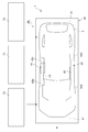
- FIG. 7 is an explanatory view in plan view of the transport apparatus 20 which has moved to the first work area A1.
- FIG. 8 is a perspective view of the conveyance device 20 for illustrating the operation of assembling a large part to the vehicle body 3 moved to the second work area A2.
- the transport device 20 is provided with the turning mechanism 60, so that the front-rear direction of the vehicle body 3 is in the line advancing direction by the turning mechanism 60. It can be in a state of facing in a direction crossing the direction opposite (in the illustrated embodiment, an orthogonal direction). For this reason, as shown in FIGS. 1 and 8, in the second work area A2, the front-rear direction of the vehicle body 3 is in the state of facing the direction intersecting the line advancing direction. The end of the can be projected outward in the width direction of the line.
- the lifting device 75 when the lifting device 75 such as a lifter is disposed on the floor Fs adjacent to the assembly line, the lifting device 75 can be any of an engine, a transmission, a motor, an inverter, a drive shaft, a suspension, a transaxle, etc.
- the large-sized parts such as the front drive unit combining the two or the rear drive unit combining any of the engine, transmission, motor, inverter, drive shaft, suspension, transaxle, etc. can do.
- a state in which the rear suspension 76 is carried into the rear side of the vehicle body 3 by the lifting and lowering device 75 is shown.
- the assembly line 10, 10 ' includes the first assembly line 11 for moving the transport device 20 from one end side to the other end side in the line extending direction.
- a second assembly line 12 arranged parallel to the first assembly line 11 for moving the conveying device 20 from the other end side to the one end side in the line extending direction, the downstream end of the first assembly line 11 and the second assembly line 12, and a line connection portion 15 which can transfer the transfer device 20 from the first assembly line 11 to the second assembly line 12 by connecting the upstream end of the first assembly line 11 to the first assembly line 11 A1 is provided, and a second work area A2 is provided downstream, the second assembly line 12 is provided with a second work area A2 upstream, and a first work area A1 downstream.
- the line connection portion 15 is a first assembly line.
- the transport device 20 is configured to be movable while maintaining the orientation of the base 50 of the transport device 20 and the vehicle body 3 in the second work area A2 of the tray 11, and the transport device 20 When it moves between the first work area A1 and the second work area A2 of the line 11, the rotation mechanism 61 moves the rotation table 61 so that the front-rear direction of the vehicle body 3 becomes a direction intersecting the line advancing direction.
- the base 50 is moved between the second work area A2 and the first work area A1 of the second assembly line 12
- the rotary table 61 is configured to rotate in a direction.
- a rotation area for changing the direction of the vehicle body 3 is provided between the first work area A1 and the second work area A2 and in the area upstream of the first work area A1. It is done.
- a rotation area is provided between the first work area A1 and the second work area A2 and in an area downstream of the first work area A1.
- the line connection portion 15 connects the downstream end of the first assembly line 11 and the upstream end of the second assembly line 12 so that the transport device 20 can be first assembled without changing the orientation of the base 50 and the vehicle body 3. It is configured to be movable from the line 11 to the second assembly line 12.
- the first assembly line 11 and the second assembly line 12 are connected via the line connection portion 15, and the line connection portion 15 sets the direction of the vehicle body 3 in the second work area A2 of the first assembly line 11.
- the transfer device 20 is configured to be movable while maintaining it. Therefore, the vehicle body 3 supported by the support portion 40 of the transfer device 20 is maintained in the same direction, and the second work area A2 of the first assembly line 11 to the second work of the second assembly line 12 It is transported to the area A2. Therefore, when the lifting device 75 (see FIG.
- the line connection portion 15 is a line connecting the first assembly line 11 and the second assembly line 12, when the first assembly line 11 and the second assembly line 12 are disposed adjacent to each other, the line The path of the connection portion 15 can be shortened. Therefore, the path between the second work areas A2 of the first assembly line 11 and the second assembly line 12 can be shortened.
- the front and back direction of the vehicle body 3 crosses the line advancing direction by the turning mechanism 60
- the rotary base 61 is turned in such a direction that the base 50 is moved between the second work area A2 and the first work area A1 of the second assembly line 12
- the turning mechanism 60 The rotation table 61 is rotated so that the front-rear direction is a direction along the line advancing direction. For this reason, it is possible to easily switch the orientation of the vehicle body suitable for each of the first assembly line 11 and the second assembly line 12.
- the support portion 40 has a horizontally extending beam portion 45 connected to the upper end of the support portion 41 as shown in FIGS.
- the receiving portions 43a and 43b protruding upward at both ends in the extending direction are provided, and the beam portions 45 of the pair of support portions 40 extend in parallel with each other in plan view, and the line of the pair of support portions 40 and 40 '
- One support portion 40 disposed on the right side in the traveling direction is a pair of reception portions provided on the other support portion 40 ′ in which the distance X R between the pair of reception portions 43 a and 43 b provided on one support portion 40 is It is configured to be smaller than the distance X L between the portions 43a and 43b.
- the distance X R between the pair of receiving portions 43 a and 43 b of one of the pair of supporting portions 40 and 40 ′ disposed on the right side in the line traveling direction is , a pair of receiving portions 43a provided on the other supporting portion 40 ', smaller than the distance X L between 43b.
- the range of the spaces Af and Ar below the vehicle body 3 on the front and rear sides in the line advancing direction with respect to the one support portion 40 is the space corresponding to the other support portion 40 '. It can be larger than that. Therefore, the large parts can be easily transported from the one support portion 40 side to the spaces Af and Ar below the front side and the rear side of the vehicle body.
- the receiving portion 43 a that abuts and supports the front portion of the vehicle body 3 among the pair of receiving portions 43 a and 43 b provided on one of the support portions 40 , the distance Y F between the strut 41 in a plan view is disposed so as to be larger than the distance Y R of the receiving portion 43b and the support portion 41 which contacts and supports a rear portion of the vehicle body 3.
- the distance X L between the pair of receiving portions 43 a and 43 b of the other supporting portion 40 ′ of the pair of supporting portions 40 and 40 ′ disposed on the left side in the line traveling direction is the pair of supporting portions 40 It is larger than the distance X R between the receiving portions 43a and 43b. Therefore, the front receiving portion 43 a of the other support portion 40 ′ is positioned in the front portion of the vehicle body 3 than the front receiving portion 43 a of the one support portion 40. For this reason, to make the position of the front receiving part 43a of the other support part 40 'disposed on the left side in the line advancing direction close to the center of gravity position on the front side of the vehicle body 3 An increase in the acting moment can be effectively suppressed.
- the support columns 41 of the supporting parts 40 and 40 ′ are erected on the rotating table 61 in a state rotated by an angle ⁇ with respect to the line advancing direction.
- the distance between the column portion 41 and the front receiving portion 43a can be shortened as compared to the case where the column portion 41 is not rotated, ie, when ⁇ is zero.
- the moment acting on the column portion 41 can be reduced, and the increase in the moment acting on the receiving portion 43a supporting the front side of the vehicle body 3 can be suppressed.
- the parts assembled to the lower part of the vehicle body 3 in the first work area A1 are small underbody parts such as insulators, braces and cables.
- the vehicle body 3 is supported by the support portion 40 in a state in which the front-rear direction of the vehicle body 3 is along the line advancing direction of the assembly line 10.
- Spaces Af and Ar are formed on the front and rear sides of the vehicle body in the front-rear direction. For this reason, small underbody parts can be attached to the lower part of the vehicle body 3 via these spaces Af and Ar.
- the parts assembled to the lower part of the vehicle body 3 in the second work area A2 are fronts combining any of an engine, a transmission, a motor, an inverter, a drive shaft, a suspension, a transaxle, etc.
- the drive unit or large parts such as a rear drive unit combining any of an engine, a transmission, a motor, an inverter, a drive shaft, a suspension, a transaxle and the like.
- the front-rear direction of the vehicle body 3 is in a state in which the front-rear direction of the vehicle body 3 faces the direction intersecting the line travel direction. It can be made to project outward in the orthogonal direction. Therefore, since the lifting device such as the mounted lifter can be disposed on the floor adjacent to the assembly line 10, this lifting device can be used to select one of the engine, transmission, motor, inverter, drive shaft, suspension, transaxle, etc.
- the large parts such as the combined front drive unit or the rear drive unit combining any of the engine, transmission, motor, inverter, drive shaft, suspension, transaxle, etc. are easily carried into the front and rear sides of the vehicle body 3 and arranged can do.
- the upper surface 61 a of the rotation base 61 may be disposed above or below the upper surface 50 a of the base 50.
Landscapes
- Engineering & Computer Science (AREA)
- Manufacturing & Machinery (AREA)
- Chemical & Material Sciences (AREA)
- Combustion & Propulsion (AREA)
- Transportation (AREA)
- Mechanical Engineering (AREA)
- Automobile Manufacture Line, Endless Track Vehicle, Trailer (AREA)
Abstract
車両の組立ラインの搬送装置は、移動可能な基台と、基台の上面に設けられた平面視円形状の回転台と、回転台上に設けられて車体下部に当接して車体を支持する支持部を備え、基台は回転台の上面に対して直交する方向に延びる中心軸に対して回転台を回動させる回動機構部を有し、支持部は回転台の上面の直径方向に離間して一対設けられ、回転台上に固定される支柱部と、この上端部に水平方向に延設された梁部と、梁部の両端部に設けられた受部とを備え、支持部は、梁部が車体前後方向に向いた状態で車体を支持し、組立ラインは、車体がライン進行方向に沿った状態で作業を行う第1作業領域と、第1作業領域での回転台の位置から回転台を回動させることで車体の前後方向がライン進行方向に対して交差する方向を向いた状態で部品組み付け作業が行われる第2作業領域と、を有する。
Description
本開示は、車両の組立ラインに関し、特に車両の足回り組立ラインに関する。
従来から、自動車等の車両を製造する際の車両組立ラインに関する技術は種々公知となっている。
例えば、特許文献1には、車体を支持した状態で床面上を移動させ、車体を組立ラインに沿って搬送する複数の搬送装置を備える車両の組立ラインが開示されている。複数の搬送装置の夫々は、車体を、車体の前後方向が車体の前記組立ラインのライン進行方向と直交する姿勢に支持する支持部と、支持部を上面に固定する基台とを有している。支持部は、前記組立ラインのライン進行方向に対して直交する方向に延びる中心線を中心として基台上に線対称に配置された上流側支持部及び下流側支持部を有している。
搬送装置に支持された状態の車体の下方の空間には、前記組立ラインのライン進行方向に沿って連通して車体に対して足まわり部品を組付けの際に使用する工具の搬送用の搬送通路が形成されている。また、搬送装置に支持された車体の下方には、搬送通路とは独立して、足回り部品を配置するための部品空間が形成されている。
このようにすることで、車体の下方の上流側支持部と下流側支持部との間に、部品載置の台車を配置することができる。更に、車体の前側部分の下方と、車体の後側部分の下方とに、搬送通路が形成され、この搬送通路を部品を取付けるための工具搬送用空間として利用できる。このため、車体の下方に、工具類を載置したワゴンと、取付部品を載置した台車を配置することができる。従って、車体に部品を組付ける際に、部品を取りに行く際の移動距離の増加を抑制でき、作業の効率化を図ることができる。
この特許文献1に記載の従来の車両の組立ラインは、車体の向きをライン進行方向に対して略直交する方向に向けた状態で支持しているため、車体の前側及び後側は組立ラインから突出した状態にある。このため、組立ラインに隣接する床面に搭載リフター等の昇降装置の配置が可能である。この昇降装置を利用して、前側及び後側サスペンション、エンジン&トランスミッション等の大型部品を車体の前側及び後側に容易に搬入して配置することができる。
しかしながら、この従来の車両の組立ラインは、車体を支持する上流側支持部及び下流側支持部の夫々の支柱間の幅が、車幅と同程度であるため狭い。このため、床下配管、燃料タンク、マフラー等の大型の部品を、車体前後方向から車体の下方の上流側支持部と下流側支持部との間の空間を介して車体の下部に搬入するのは煩わしい。従って、部品の車体下部への組付け作業の効率が低下する虞がある。
本発明の少なくとも一つの実施形態は、このような従来技術の状況の基になされた発明であって、その目的とするところは、車体下部への部品の組付け作業の効率化を図ることができる車両の組立ラインを提供することを目的とする。
(1)本発明の少なくとも一つの実施形態にかかる車両の組立ラインは、車体を支持した状態で前記車体を組立ラインに沿って搬送する搬送装置を複数備え、前記搬送装置に支持される車体の下部に部品を組付ける車両の組立ラインであって、前記搬送装置は、前記組立ラインのライン進行方向に移動可能な基台と、前記基台の上面に設けられた回転台と、前記回転台に取り付けられて上方へ延びて前記車体の下部に当接して前記車体を支持する支持部と、を備え、前記回転台は、平面視において円形状に形成されて前記回転台の上面に対して直交する方向に延びる中心軸を中心として回動自在に設けられ、前記基台は、前記回転台を回動させる回動機構部が設けられ、前記支持部は、前記回転台の上面の直径方向に離間して一対設けられ、前記回転台の上面に固定されて上方へ延びる支柱部と、前記支柱部の上端部に取り付けられて前記支柱部を間にして水平方向両側に延びる梁部と、前記梁部の延伸方向両端部に設けられて前記車体を当接支持する受部と、を備え、前記支持部は、前記梁部の延伸方向が前記車体の前後方向に沿った状態で前記車体を支持し、前記組立ラインは、車体の前後方向が前記組立ラインのライン進行方向に沿った状態で部品組み付け作業が行われる第1作業領域と、前記第1作業領域での前記回転台の位置から前記回転台を回動させることで車体の前後方向がライン進行方向に対して交差する方向を向いた状態で部品組み付け作業が行われる第2作業領域と、を有する。
上記(1)に記載の車両の組立ラインによれば、支持部は、前記梁部の延伸方向が前記車体の前後方向に沿った状態で前記車体を支持している。このため、第1作業領域では、車体は、車体の前後方向が組立ラインのライン進行方向に沿った状態で支持部に支持される。支持部の支柱部よりも車体前後方向前側と後側には、空間が形成される。このため、組立ラインのライン進行方向一方側に部品棚を設置した場合には、搬送装置が第1作業領域に移動すると、部品棚から取り出された部品を、支柱部の車体前後方向前側と後側に形成された空間を介して、車体前側や後側に容易に搬入して組み付けることができる。
また、搬送装置には回転台及び回動機構部が設けられているので、車体の前後方向がライン進行方向に対して交差する方向を向いた状態にすることができる。このため、第2作業領域では、車体の前後方向がライン進行方向に対して交差する方向を向いた状態になるので、車体の前後方向の夫々の端部を組立ラインの進行方向に対して直交する方向の外側へ突出した状態にすることができる。したがって、組立ラインに隣接する床面に搭載リフター等の昇降装置を配置した場合には、この昇降装置によって、例えば、前側及び後側サスペンション、エンジン&トランスミッション等の部品を車体の前側及び後側に容易に搬入して組み付けることができる。
よって、車体下部への部品の組付け作業の効率化を図ることが可能な車両の組立ラインを実現できる。
(2)幾つかの実施形態では、上記(1)に記載の車両の組立ラインにおいて、一対の前記支持部の夫々の梁部は、平面視において平行に配設され、一対の前記支持部の夫々の支柱部は、平面視において前記支柱部に設けられた梁部の延伸方向に対して傾いた方向を向いた状態で前記回転台上に固定されているように構成される。
上記(2)に記載の実施形態によれば、支柱部は、平面視において支柱部に設けられた梁部の延伸方向に対して傾いた方向を向いた状態で回転台上に固定されている。このため、平面視において支柱部に車体前後方向及び車体幅方向の少なくともいずれかの成分を有した外力が作用した場合、この外力によって支柱部が大きく変形することなく外力を受けることができる。したがって、車体を安定に支持することができる。
(3)幾つかの実施形態では、上記(2)に記載の車両の組立ラインにおいて、一対の前記支持部のうち一方の支持部は、前記一方の支持部に設けられた一対の受部間の距離が、他方の支持部に設けられた一対の受部間の距離よりも小さくなるように構成されている。
上記(3)に記載の実施形態によれば、一対の支持部のうち一方の支持部は、一方の支持部に設けられた一対の受部間の距離が、他方の支持部に設けられた一対の受部間の距離よりも小さい。このため、一方の支持部のライン進行方向前側及び後側の夫々の車体の下方の空間の領域を、他方の支持部の対応する空間の領域よりも大きくすることができる。
(4)幾つかの実施形態では、上記(3)に記載の車両の組立ラインにおいて、前記第1作業領域では、前記組立ラインの両側方の内、前記一方の支持部が配置される側の側方から部品が搬入される。
上記(4)に記載の実施形態によれば、第1作業領域では、組立ラインの両側方の内、一方の支持部が設けられた側の側方から部品が搬入されるため、車体の下方の空間の領域を、他方の支持部の対応する空間の領域よりも大きくすることができ、車体の下方の空間の領域に車両の部品を容易に搬送することができる。
(5)幾つかの実施形態では、上記(3)又は(4)に記載の車両の組立ラインにおいて、前記一方の支持部に設けられた一対の受部のうち前記車体の前側部分を当接支持する受部は、平面視において前記支柱部との距離が、前記車体の後側部分を当接支持する受部と前記支柱部との距離よりも大きくなるように配設されている。
車体の前側にエンジンルームが形成された車体では、車体にエンジンが搭載されると、車体の前側の重さは後側と比較して重くなる。このため、車体の前側を安定支持するためには、車体の前側部分を当接支持する受部の位置を車体の前側の重心位置に近づける必要がある。そこで、上記(5)に記載の実施形態によれば、車体の前側部分を当接支持する受部は、平面視における受部と支柱部との距離が、車体の後側部分を当接支持する受部と支柱部との距離よりも大きくすることで、車体の前側を支持する受部に作用するモーメントの増大を抑えることができ、車体の前側を安定支持することができる。
(6)幾つかの実施形態では、上記(1)から(5)のいずれか1項に記載の車両の組立ラインにおいて、前記第1作業領域において前記車体の下部に組み付けられる部品は、インシュレータ、ブレース、ケーブルの内、少なくとも一つを含む足回り部品である。
上記(6)に記載の実施形態によれば、第1作業領域において車体の下部に組み付けられる部品は、インシュレータ、ブレース、ケーブルの内、少なくとも一つを含む足回り部品である。第1作業領域では、車体は、車体の前後方向が組立ラインのライン進行方向に沿った状態で支持部に支持されるので、支持部の支柱部よりも車体前後方向前側と後側には、空間が形成される。このため、インシュレータ、ブレース、ケーブルの内、少なくとも一つを含む足回り部品をこれらの空間を介して車体の下部に組み付けることができる。
(7)幾つかの実施形態では、上記(1)から(6)のいずれか1項に記載の車両の組立ラインにおいて、前記第2作業領域において前記車体の下部に組み付けられる部品は、フロントドライブユニット又はリアドライブユニットである。
上記(7)に記載の実施形態によれば、第2作業領域において車体の下部に組み付けられる部品は、フロントドライブユニット又はリアドライブユニットである。第2作業領域では、車体の前後方向がライン進行方向に対して交差する方向を向いた状態になるので、車体の前後方向の夫々の端部を組立ラインの進行方向に対して直交する方向の外側へ突出した状態にすることができる。したがって、組立ラインに隣接する床面に搭載リフター等の昇降装置を配置することができるので、この昇降装置によって、フロントドライブユニット又はリアドライブユニットを車体の前側及び後側に容易に搬入して組み付けることができる。
(8)幾つかの実施形態では、上記(1)から(7)のいずれか1項に記載の車両の組立ラインにおいて、前記組立ラインは、ライン延伸方向一端側から他端側へ向かって前記搬送装置を移動させる第1組立ラインと、前記第1組立ラインと並設されて前記第1組立ラインのライン延伸方向他端側から一端側へ向かって前記搬送装置を移動させる第2組立ラインと、前記第1組立ラインの下流側端と前記第2組立ラインの上流側端とを繋いで前記搬送装置を前記第1組立ラインから前記第2組立ラインへ移動可能なライン接続部とを備え、前記第1組立ラインは、上流側に第1作業領域が設けられ、且つ下流側に第2作業領域が設けられ、前記第2組立ラインは、上流側に第2作業領域が設けられ、且つ下流側に第1作業領域が設けられ、前記ライン接続部は、前記第1組立ラインの第2作業領域での前記搬送装置の前記基台及び前記車体の向きを維持したままで前記搬送装置を移動可能に構成され、前記搬送装置は、この基台が前記第1組立ラインの第1作業領域と第2作業領域との間に移動すると、前記回動機構部によって車体の前後方向がライン進行方向に対して交差する方向になるように前記回転台を回動し、前記基台が前記第2組立ラインの第2作業領域と第1作業領域との間に移動すると、前記回動機構部によって前記車体の前後方向がライン進行方向に沿った方向になるように前記回転台を回動するように構成されている。
上記(8)に記載の実施形態によれば、第1組立ラインと第2組立ラインは、ライン接続部を介して繋がり、ライン接続部は、第1組立ラインの第2作業領域での車体の向きを維持したままで搬送装置を移動可能に構成されている。このため、搬送装置の支持部で支持された車体は、その向きが同一向きに維持されたままで、第1組立ラインの第2作業領域から第2組立ラインの第2作業領域に搬送される。したがって、第1組立ライン及び第2組立ラインの夫々のライン進行方向右側に、部品を昇降可能な昇降装置を設置する場合には、昇降装置によって車両の前側及び後側に重量部品を容易に搬入して配置することができる。また、ライン接続部は第1組立ラインと第2組立ラインを繋ぐラインであるので、第1組立ライン及び第2組立ラインが隣接して配設されているので、ライン接続部の経路を短縮化することができる。従って、第1組立ライン及び第2組立ラインの夫々の第2作業領域間の経路を短縮化することができる。
本発明の少なくとも幾つかの実施形態によれば、車体下部への部品の組付け作業の効率化を図ることができる車両の組立ラインを提供することができる。
以下、添付図面に従って本発明の車両の組立ラインの実施形態について、図1~図8を参照しながら説明する。ただし、実施形態として記載されている又は図面に示されている構成部品の寸法、剤質、形状、その相対的配置等は、本発明の範囲をこれに限定する趣旨ではなく、単なる説明例にすぎない。例えば、「ある方向に」、「ある方向に沿って」、「平行」、「直交」、「中心」、「同心」或いは「同軸」等の相対的或いは絶対的な配置を表す表現は、厳密にそのような配置を表すのみならず、公差、若しくは、同じ機能が得られる程度の角度や距離をもって相対的に変位している状態も表すものとする。例えば、「同一」、「等しい」及び「均質」等の物事が等しい状態であることを表す表現は、厳密に等しい状態を表すのみならず、公差、若しくは、同じ機能が得られる程度の差が存在している状態も表すものとする。例えば、四角形状や円筒形状等の形状を表す表現は、幾何学的に厳密な意味での四角形状や円筒形状等の形状を表すのみならず、同じ効果が得られる範囲で、凹凸部や面取り部等を含む形状も表すものとする。一方、一の構成要素を「備える」、「具える」、「具備する」、「含む」、又は、「有する」という表現は、他の構成要素の存在を除外する排他的な表現ではない。また、以下の説明において、同じ構成には同じ符号を付してその詳細な説明を省略する場合がある。
図1は、本発明の一実施形態である車両の組立ラインの全体平面図である。図2は、搬送装置の斜視図である。図3は、車体を支持する搬送装置の側面図である。図4は、車体を支持する搬送装置の正面図である。図5は、搬送装置に設けられた回動機構部を示し、同図(a)は、回動機構部の平面図であり、同図(b)は、回動機構部の側面図であり、同図(c)は、回動機構部の正面図である。なお、本実施形態は、車体の下部に部品を組み付けるための車両の組立ラインについて説明する。
本発明の一実施形態に係る車両の組立ライン1は、図1、図2、図3に示すように、車体3を支持した状態で車体3を組立ライン10、10'に沿って搬送する搬送装置20を複数備え、搬送装置20に支持される車体3の下部に部品を組付ける車両の組立ライン1であって、搬送装置20は、床面Fs上に配設されたレールRに沿って移動可能な基台50と、基台50の上面50aの一部に設けられた回転台61と、回転台61上に取り付けられて上方へ延びて車体3の下部に当接して車体3を支持する支持部40と、を備え、回転台61は、平面視において円形状に形成されて回転台61の上面61aに対して直交する方向に延びる中心軸を中心として回動自在に設けられ、基台50には、回転台61を回動させる回動機構部60が設けられ、支持部40は、回転台61の上面61aの直径方向両端部に一対設けられ、回転台61の上面61aに固定されて上方へ延びる支柱部41と、支柱部41の上端部に取り付けられて支柱部41を中央にして水平方向両側に延びる梁部45と、梁部45の延伸方向両端部に設けられて車体3を当接支持する受部43と、を備え、支持部40は、梁部45の延伸方向が車体3の前後方向に沿った状態で車体3を支持し、組立ライン1は、車体3の前後方向が組立ライン1のライン進行方向に沿った状態で部品組み付け作業が行われる第1作業領域A1と、車体3の前後方向がライン進行方向に対して交差する方向を向いた状態で部品組み付け作業が行われる第2作業領域A2と、を含み、回動機構部60は、第1作業領域A1及び第2作業領域A2の夫々の領域に応じた車体3の向きになるように回転台61を回動するように構成される。
図示した実施形態では、組立ライン1は、2本あり、これらの組立ライン10、10'は並設されている。2本の組立ライン10、10'のうち、上流側の組立ライン10は、ライン進行方向上流側に第1作業領域A1が設けられ、第1作業領域A1の下流側に第2作業領域A2が設けられている。また、第1作業領域A1の上流側には、組立ライン10に車体3を搬入して向きを回転させる車両搬入領域Aiが設けられている。
また、2本の組立ライン10、10'のうち、下流側の組立ライン10'は、ライン進行方向上流側に第2作業領域A2が設けられ、下流側に第1作業領域A1が設けられている。さらに、第1作業領域A1の下流側には、車体3の向きを変えて組立ライン10'から車体3を搬出する車両搬出領域Aoが設けられている。
また、図示した実施形態では、組立ライン10、10'の夫々には、2本のレールRが床面Fs上に並設され、これらのレールRには、搬送装置20を移送させるための搬送従動綸70(図3参照)が回転自在に多数設けられている。そして、これらのレールRの側部には、搬送装置20の基台50の側部に当接して、搬送装置20をライン進行方向に搬送する図示しない搬送駆動部が配設されている。
また、図示した実施形態では、基台50は、図2に示すように、その上面50aの中央部に孔部50bが設けられている。この孔部50b内に回転台61が設けられている。この回転台61は、回転台61に対して直交する方向に延びる中心軸を中心として回動自在に支持されている。回転台61の上面61aは、基台50の上面50aと略同一平面上に配置されている。回動機構部60は、図5(a)、図5(b)、図5(c)に示すように、回転台61の下面61bに設けられた回転駆動部63と、回転台61の回動をロックする回動規制部65とを備える。
回転駆動部63は、回転台61の下面61bに設けられたウォームホイール63aと、ウォームホイール63aに歯合するウォームギヤ63bと、ウォームギヤ63bを回転駆動させる電動モータ63cとを備える。ウォームホイール63aの回転中心は回転台61の回転中心Oと同軸上に配設されている。ウォームギヤ63bは電動モータ63cの回転軸63c1に固定されている。電動モータ63cは、前述した組立ライン10、10'のうち車体3を回転させる回転領域、即ち、上流側の組立ライン10の第2作業領域A2と第1作業領域A1との間の領域A4、下流側の組立ライン10'の第2作業領域A2と第1作業領域A1との間の領域A4、車両搬入領域Ai、車両搬出領域Aoに配設されている。
電動モータ63cは、搬送装置20が車体3を回転させる領域に移動したときにウォームホイール63aからウォームギヤ63bが離れる離反位置と、ウォームギヤ63bがウォームホイール63aと歯合する歯合位置との間を移動可能に構成されている。このように、電動モータ63cを搬送装置20が車体3を回転させる領域のみに配設することで、電動モータ63cを搬送装置20毎に設ける場合と比較して、コストの低減や電動モータ63cに繋がる配線の引き回しの簡素化を図ることができる。
回動規制部65は、回転台61の下面61bに突設された複数の突起部66と、突起部66に形成された係合孔部66aに係合可能な係止突起部67を移動自在に支持する駆動シリンダ68とを備える。突起部66は回転台61の下面61bに周方向に等間隔に設けられている。図示した実施形態では、周方向に90°の角度を有して3つの突起部66が設けられている。駆動シリンダ68が伸長して係止突起部67が係合孔部66aに係合すると、回転台61の回転を規制することができる。駆動シリンダ68の駆動源は、空気、油圧等のいずれでもよい。
図示した実施形態では、図6に示すように、一対の支持部40の夫々の梁部45は、平面視において平行に配設され、一対の支持部40の夫々の支柱部41は、平面視において支柱部41に設けられた梁部45の延伸方向に対して傾いた方向を向いた状態で回転台61の上面61a上に固定されているように構成される。
すなわち、支柱部41は平面視における断面形状が四角形状を有し、その断面形状の中心線が梁部45の延伸方向の中心線に対して傾いている。
本実施形態では、支柱部41は、回転台61上に固定されている。一対の支柱部41のそれぞれの内側側面は、回転台61の回転中心O側に向かって互いに対向配置されている。本実施形態では、支柱部41の中心線は梁部45の中心線に対して約20度の角度θを有して傾いている。
すなわち、支柱部41は平面視における断面形状が四角形状を有し、その断面形状の中心線が梁部45の延伸方向の中心線に対して傾いている。
本実施形態では、支柱部41は、回転台61上に固定されている。一対の支柱部41のそれぞれの内側側面は、回転台61の回転中心O側に向かって互いに対向配置されている。本実施形態では、支柱部41の中心線は梁部45の中心線に対して約20度の角度θを有して傾いている。
このように、支柱部41は、平面視において支柱部41に設けられた梁部45の延伸方向に対して傾いた方向を向いた状態で回転台61の上面61aに固定されている。このため、平面視において支柱部41に車体前後方向及び車体幅方向の少なくともいずれかの成分を有した外力が作用した場合、この外力によって支柱部41が大きく変形することなく外力を受けることができる。したがって、車体3を安定に支持することができる。
図6は、車体3を支持する支持部40の平面図である。図7は、第1作業領域A1に移動した搬送装置20の平面視における説明図である。図8は、第2作業領域A2に移動した車体3に大型部品を組み付ける作業を説明するための搬送装置20の斜視図である。
このように、搬送装置20が第1作業領域A1に移動すると、図3及び図6に示すように、搬送装置20をライン進行方向に対して直交する方向から見ると、一対の支持部40よりも車体前後方向前側と後側には、図7に示すように、空間Af、Arが形成される。このため、組立ライン1のライン進行方向一方側に部品棚73を設置した場合には、搬送装置20が第1作業領域A1に移動すると、部品棚73から取り出された部品を、支持部40の車体前後方向前側と後側に形成された空間Af、Arを介して、車体前側や後側に容易に搬入して配置することができる。
また、搬送装置20には、図2、図5(a)に示すように、回動機構部60が設けられているので、回動機構部60によって、車体3の前後方向がライン進行方向に対して交差する方向を向いた状態(図示した実施形態では、直交する方向)にすることができる。このため、図1及び図8に示すように、第2作業領域A2では、車体3の前後方向がライン進行方向に対して交差する方向を向いた状態になるので、車体3の前後方向の夫々の端部をラインの幅方向外側へ突出した状態にすることができる。したがって、組立ラインに隣接する床面Fsに搭載リフター等の昇降装置75を配置した場合には、この昇降装置75によって、エンジン、トランスミッション、モータ、インバータ、ドライブシャフト、サスペンション、トランスアクスルなどのいずれかを組み合わせたフロントドライブユニット、又は、エンジン、トランスミッション、モータ、インバータ、ドライブシャフト、サスペンション、トランスアクスルなどのいずれかを組み合わせたリアドライブユニットなどの大型部品を車体の前側及び後側に容易に搬入して配置することができる。図示した実施形態では、昇降装置75によって、後側サスペンション76を車体3の後側に搬入している様子を示している。
よって、車体下部への部品の組付け作業の効率化を図ることが可能な車両の組立ラインを実現できる。
また、幾つかの実施形態によれば、組立ライン10、10'は、図1に示すように、ライン延伸方向一端側から他端側へ向かって搬送装置20を移動させる第1組立ライン11と、第1組立ライン11と並設されてライン延伸方向他端側から一端側へ向かって搬送装置20を移動させる第2組立ライン12と、第1組立ライン11の下流側端と第2組立ライン12の上流側端とを繋いで搬送装置20を第1組立ライン11から第2組立ライン12へ移動可能なライン接続部15とを備え、第1組立ライン11は、上流側に第1作業領域A1が設けられ、且つ下流側に第2作業領域A2が設けられ、第2組立ライン12は、上流側に第2作業領域A2が設けられ、且つ下流側に第1作業領域A1が設けられ、ライン接続部15は、第1組立ライン11の第2作業領域A2での搬送装置20の基台50及び車体3の向きを維持したままで搬送装置20を移動可能に構成され、搬送装置20は、この基台50が第1組立ライン11の第1作業領域A1と第2作業領域A2との間に移動すると、回動機構部60によって車体3の前後方向がライン進行方向に対して交差する方向になるように回転台61を回動し、基台50が第2組立ライン12の第2作業領域A2と第1作業領域A1との間に移動すると、回動機構部60によって車体3の前後方向がライン進行方向に沿った方向になるように回転台61を回動するように構成されている。
図示した実施形態では、第1組立ライン11では、第1作業領域A1と第2作業領域A2との間、第1作業領域A1よりも上流側の領域に車体3の向きを変える回転領域が設けられている。また、第2組立ライン12では、第1作業領域A1と第2作業領域A2との間、第1作業領域A1よりも下流側の領域に回転領域が設けられている。
ライン接続部15は、第1組立ライン11の下流側端と第2組立ライン12の上流側端とを繋いで、基台50及び車体3の向きを変えることなく、搬送装置20を第1組立ライン11から第2組立ライン12へ移動可能に構成されている。
このように、第1組立ライン11と第2組立ライン12は、ライン接続部15を介して繋がり、ライン接続部15は、第1組立ライン11の第2作業領域A2での車体3の向きを維持したままで搬送装置20を移動可能に構成されている。このため、搬送装置20の支持部40で支持された車体3は、その向きが同一向きに維持されたままで、第1組立ライン11の第2作業領域A2から第2組立ライン12の第2作業領域A2に搬送される。したがって、第1組立ライン11のライン進行方向右側の床面Fs及び第2組立ライン12のライン進行方向右側に、重量部品を昇降可能な昇降装置75(図8参照)を設置すると、昇降装置75によって車体3の前側及び後側に重量部品を容易に搬入して配置することができる。また、ライン接続部15は第1組立ライン11と第2組立ライン12を繋ぐラインであるので、第1組立ライン11及び第2組立ライン12が隣接して配設されている場合には、ライン接続部15の経路を短縮化することができる。従って、第1組立ライン11及び第2組立ライン12の夫々の第2作業領域A2間の経路を短縮化することができる。
また、基台50が第1組立ライン11の第1作業領域A1と第2作業領域A2との間に移動すると、回動機構部60によって車体3の前後方向がライン進行方向に対して交差する方向になるように回転台61を回動し、基台50が第2組立ライン12の第2作業領域A2と第1作業領域A1との間に移動すると、回動機構部60によって車体3の前後方向がライン進行方向に沿った方向になるように回転台61を回動する。このため、第1組立ライン11及び第2組立ライン12の夫々に適した車体の向きを容易に切り換えることができる。
また、幾つかの実施形態によれば、支持部40は、図2及び図6に示すように、支柱部41の上端に接続されて水平方向に延びる梁部45を有し、梁部45の延伸方向両端部に上方へ突出する受部43a、43bが設けられ、一対の支持部40の夫々の梁部45は、平面視において互いに平行に延び、一対の支持部40、40'のうちライン進行方向右側に配置される一方の支持部40は、一方の支持部40に設けられた一対の受部43a、43b間の距離XRが、他方の支持部40'に設けられた一対の受部43a、43b間の距離XLよりも小さくなるように構成されている。
図示した実施形態では、図6に示すように、一対の支持部40、40'のうちライン進行方向右側に配置される一方の支持部40の一対の受部43a、43b間の距離XRは、他方の支持部40'に設けられた一対の受部43a、43b間の距離XLよりも小さい。このため、図7に示すように、一方の支持部40よりもライン進行方向前側及び後側の夫々の車体3の下方の空間Af、Arの範囲を、他方の支持部40'の対応する空間よりも大きくすることができる。従って、大型部品を、一方の支持部40側から車体前側及び車体後側の下方の空間Af、Arに容易に搬送することができる。
また、幾つかの実施形態によれば、図6に示すように、一方の支持部40に設けられた一対の受部43a、43bのうち車体3の前側部分を当接支持する受部43aは、平面視において支柱部41との距離YFが、車体3の後側部分を当接支持する受部43bと支柱部41との距離YRよりも大きくなるように配設されている。
図6に図示した実施形態では、車体3の前側にエンジンルームが形成されている場合、車体3にエンジンが搭載されると、車体3の前側の重さは後側と比較して重くなる。このため、車体3の前側を安定支持するためには、車体3の前側部分を当接支持する受部43aの位置を車体3の前側の重心位置に近づける必要がある。そこで、車体3の前側部分を当接支持する受部43aは、平面視における受部43aと支柱部41との距離YFが、車体3の後側部分を当接支持する受部43bと支柱部41との距離YRよりも大きくすることで、車体3の前側を支持する受部43aに作用するモーメントの増大を抑えることができ、車体3の前側を安定支持することができる。
一対の支持部40、40'のうちライン進行方向左側に配置される他方の支持部40'の一対の受部43a、43b間の距離XLは、一方の支持部40に設けられた一対の受部43a、43b間の距離XRよりも大きい。
従って、他方の支持部40'の前側の受部43aは、一方の支持部40の前側の受部43aよりも車体3の前方部分に位置される。このため、ライン進行方向左側に配置される他方の支持部40'の前側の受部43aの位置を車体3の前側の重心位置に近づけることが、エンジンが搭載された後における、受部43aに作用するモーメントの増大を効果的に抑制することができる。
従って、他方の支持部40'の前側の受部43aは、一方の支持部40の前側の受部43aよりも車体3の前方部分に位置される。このため、ライン進行方向左側に配置される他方の支持部40'の前側の受部43aの位置を車体3の前側の重心位置に近づけることが、エンジンが搭載された後における、受部43aに作用するモーメントの増大を効果的に抑制することができる。
また、支持部40、40'の支柱部41は、梁部45がライン進行方向に位置されるときには、ライン進行方向に対して角度θだけ回転した状態で回転台61に立設される。支柱部41が角度θだけ回転した状態であると、回転しない場合、すなわちθがゼロの場合に比べて、支柱部41と前側の受部43aとの距離を短くできるため、梁部45を介して支柱部41に作用するモーメントを減少することができ、車体3の前側を支持する受部43aに作用するモーメントの増大を抑えることができる。
また、幾つかの実施形態によれば、第1作業領域A1において車体3の下部に組み付けられる部品は、インシュレータ、ブレース、ケーブル等の小型の足回り部品である。
このように、第1作業領域A1では、車体3は、車体3の前後方向が組立ライン10のライン進行方向に沿った状態で支持部40に支持されるので、支持部40の支柱部41よりも車体前後方向前側と後側には、空間Af、Arが形成される。このため、小型の足回り部品をこれらの空間Af、Arを介して車体3の下部に組み付けることができる。
また、幾つかの実施形態によれば、第2作業領域A2において車体3の下部に組み付けられる部品は、エンジン、トランスミッション、モータ、インバータ、ドライブシャフト、サスペンション、トランスアクスルなどのいずれかを組み合わせたフロントドライブユニット、又は、エンジン、トランスミッション、モータ、インバータ、ドライブシャフト、サスペンション、トランスアクスルなどのいずれかを組み合わせたリアドライブユニット等の大型の部品である。
第2作業領域A2では、車体3の前後方向がライン進行方向に対して交差する方向を向いた状態になるので、車体3の前後方向の夫々の端部を組立ライン10の進行方向に対して直交する方向の外側へ突出した状態にすることができる。したがって、組立ライン10に隣接する床面に搭載リフター等の昇降装置を配置することができるので、この昇降装置によって、エンジン、トランスミッション、モータ、インバータ、ドライブシャフト、サスペンション、トランスアクスルなどのいずれかを組み合わせたフロントドライブユニット、又は、エンジン、トランスミッション、モータ、インバータ、ドライブシャフト、サスペンション、トランスアクスルなどのいずれかを組み合わせたリアドライブユニット等の大型部品を車体3の前側及び後側に容易に搬入して配置することができる。
以上、本発明の好ましい形態について説明したが、本発明は上記の形態に限定されるものではなく、本発明の目的を逸脱しない範囲での種々の変更が可能である。例えば、回転台61は、その上面61aが基台50の上面50aよりも上方位置又は下方位置に配設されてもよい。
1 車両の組立ライン
3 車体
10、10' 組立ライン
11 第1組立ライン
12 第2組立ライン
15 ライン接続部
20 搬送装置
40 支持部
41 支柱部
43a、43b 受部
45 梁部
50 基台
50a、61a 上面
50b 孔部
60 回動機構部
61 回転台
61b 下面
63 回転駆動部
63a ウォームホイール
63b ウォームギヤ
63c 電動モータ
63c1 回転軸
65 回動規制部
66 突起部
66a 係合孔部
67 係止突起部
68 駆動シリンダ
70 搬送従動綸
73 部品棚
75 昇降装置
76 後側サスペンション
A1 第1作業領域
A2 第2作業領域
Ai 車両搬入領域
Af、Ak 空間
A3、A4 領域
Ao 車両搬出領域
Fs 床面
R レール
3 車体
10、10' 組立ライン
11 第1組立ライン
12 第2組立ライン
15 ライン接続部
20 搬送装置
40 支持部
41 支柱部
43a、43b 受部
45 梁部
50 基台
50a、61a 上面
50b 孔部
60 回動機構部
61 回転台
61b 下面
63 回転駆動部
63a ウォームホイール
63b ウォームギヤ
63c 電動モータ
63c1 回転軸
65 回動規制部
66 突起部
66a 係合孔部
67 係止突起部
68 駆動シリンダ
70 搬送従動綸
73 部品棚
75 昇降装置
76 後側サスペンション
A1 第1作業領域
A2 第2作業領域
Ai 車両搬入領域
Af、Ak 空間
A3、A4 領域
Ao 車両搬出領域
Fs 床面
R レール
Claims (8)
- 車体を支持した状態で前記車体を組立ラインに沿って搬送するように構成された搬送装置を複数備え、前記搬送装置に支持される車体の下部に部品を組付けるための車両の組立ラインであって、
前記搬送装置は、前記組立ラインのライン進行方向に移動可能な基台と、前記基台の上面に設けられた回転台と、前記回転台に取り付けられて上方へ延びて前記車体の下部に当接して前記車体を支持する支持部と、を備え、
前記回転台は、平面視において円形状に形成されて前記回転台の上面に対して直交する方向に延びる中心軸を中心として回動自在に設けられ、
前記基台には、前記回転台を回動させる回動機構部が設けられ、
前記支持部は、前記回転台の上面の直径方向に離間して一対設けられ、前記回転台の上面に固定されて上方へ延びる支柱部と、前記支柱部の上端部に取り付けられて前記支柱部を間にして水平方向両側に延びる梁部と、前記梁部の延伸方向両端部に設けられて前記車体を当接支持するための受部と、を備え、
前記支持部は、前記梁部の延伸方向が前記車体の前後方向に沿った状態で前記車体を支持するように構成され、
前記組立ラインは、車体の前後方向が前記組立ラインのライン進行方向に沿った状態で部品組み付け作業が行われる第1作業領域と、前記第1作業領域での前記回転台の位置から前記回転台を回動させることで車体の前後方向がライン進行方向に対して交差する方向を向いた状態で部品組み付け作業が行われる第2作業領域と、を有することを特徴とする車両の組立ライン。 - 一対の前記支持部の夫々の梁部は、平面視において平行に配設され、
一対の前記支持部の夫々の支柱部は、平面視において前記支柱部の断面形状の中心線が前記梁部の延伸方向の中心線に対して傾いた方向を向いた状態で前記回転台上に固定されている
ことを特徴とする請求項1に記載の車両の組立ライン。 - 一対の前記支持部のうち一方の支持部は、前記一方の支持部に設けられた一対の受部間の距離が、他方の支持部に設けられた一対の受部間の距離よりも小さくなるように構成されている
ことを特徴とする請求項2に記載の車両の組立ライン。 - 前記第1作業領域では、前記組立ラインの両側方の内、前記一方の支持部が配置される側の側方から部品が搬入される
ことを特徴とする請求項3に記載の車両の組立ライン。 - 前記一方の支持部に設けられた一対の受部のうち前記車体の前側部分を当接支持するための受部は、平面視において前記支柱部との距離が、前記車体の後側部分を当接支持するための受部と前記支柱部との距離よりも大きくなるように配設されている
ことを特徴とする請求項3又は4に記載の車両の組立ライン。 - 前記第1作業領域において前記車体の下部に組み付けられる部品は、インシュレータ、ブレース、又はケーブルの内、少なくとも一つを含む足回り部品である
ことを特徴とする請求項1から5のいずれか1項に記載の車両の組立ライン。 - 前記第2作業領域において前記車体の下部に組み付けられる部品は、フロントドライブユニット又はリアドライブユニットの少なくとも一方を含む部品である
ことを特徴とする請求項1から6のいずれか1項に記載の車両の組立ライン。 - 前記組立ラインは、
ライン延伸方向一端側から他端側へ向かって前記搬送装置を移動させる第1組立ラインと、
前記第1組立ラインと並設されて前記第1組立ラインのライン延伸方向他端側から一端側へ向かって前記搬送装置を移動させる第2組立ラインと、
前記第1組立ラインの下流側端と前記第2組立ラインの上流側端とを繋いで前記搬送装置を前記第1組立ラインから前記第2組立ラインへ移動可能なライン接続部とを備え、
前記第1組立ラインは、上流側に第1作業領域が設けられ、且つ下流側に第2作業領域が設けられ、
前記第2組立ラインは、上流側に第2作業領域が設けられ、且つ下流側に第1作業領域が設けられ、
前記ライン接続部は、前記第1組立ラインの第2作業領域での前記搬送装置の前記基台及び前記車体の向きを維持したままで前記搬送装置を移動可能に構成され、
前記搬送装置は、前記基台が前記第1組立ラインの第1作業領域と第2作業領域との間に移動すると、前記回動機構部によって車体の前後方向がライン進行方向に対して交差する方向になるように前記回転台を回動し、前記基台が前記第2組立ラインの第2作業領域と第1作業領域との間に移動すると、前記回動機構部によって前記車体の前後方向がライン進行方向に沿った方向になるように前記回転台を回動するように構成されている
ことを特徴とする請求項1から7のいずれか1項に記載の車両の組立ライン。
Priority Applications (2)
| Application Number | Priority Date | Filing Date | Title |
|---|---|---|---|
| CN201780057402.7A CN109715481B (zh) | 2016-09-20 | 2017-03-16 | 车辆组装线 |
| PH12019500581A PH12019500581A1 (en) | 2016-09-20 | 2019-03-18 | Vehicle assembly line |
Applications Claiming Priority (2)
| Application Number | Priority Date | Filing Date | Title |
|---|---|---|---|
| JP2016-183525 | 2016-09-20 | ||
| JP2016183525A JP6686819B2 (ja) | 2016-09-20 | 2016-09-20 | 車両の組立ライン |
Publications (1)
| Publication Number | Publication Date |
|---|---|
| WO2018055809A1 true WO2018055809A1 (ja) | 2018-03-29 |
Family
ID=61689906
Family Applications (1)
| Application Number | Title | Priority Date | Filing Date |
|---|---|---|---|
| PCT/JP2017/010710 Ceased WO2018055809A1 (ja) | 2016-09-20 | 2017-03-16 | 車両の組立ライン |
Country Status (4)
| Country | Link |
|---|---|
| JP (1) | JP6686819B2 (ja) |
| CN (1) | CN109715481B (ja) |
| PH (1) | PH12019500581A1 (ja) |
| WO (1) | WO2018055809A1 (ja) |
Cited By (2)
| Publication number | Priority date | Publication date | Assignee | Title |
|---|---|---|---|---|
| CN109848912A (zh) * | 2019-04-01 | 2019-06-07 | 重庆赛科机电技术服务有限公司 | 一种发动机合装托盘 |
| CN112606927A (zh) * | 2020-12-21 | 2021-04-06 | 苏州冬宝光电科技有限公司 | 一种新能源智能观光车自动组装线 |
Citations (3)
| Publication number | Priority date | Publication date | Assignee | Title |
|---|---|---|---|---|
| JP2002087576A (ja) * | 2000-09-14 | 2002-03-27 | Honda Motor Co Ltd | パレット搬送機構およびそれを用いた組立ライン |
| JP2010188790A (ja) * | 2009-02-16 | 2010-09-02 | Toyota Motor Corp | 車両の組立ライン |
| JP2014136291A (ja) * | 2013-01-17 | 2014-07-28 | Kawasaki Heavy Ind Ltd | 車両の組立ライン装置 |
Family Cites Families (5)
| Publication number | Priority date | Publication date | Assignee | Title |
|---|---|---|---|---|
| KR20020094560A (ko) * | 2001-06-12 | 2002-12-18 | 현대자동차주식회사 | 샤시 라인 플로어 대차방식 컨베이어 |
| JP4600841B2 (ja) * | 2008-04-03 | 2010-12-22 | 株式会社ダイフク | 自動車などの組立て用搬送装置 |
| DE202011051375U1 (de) * | 2011-07-22 | 2011-10-12 | IBG Technology Hansestadt Lübeck GmbH | Fördersystem zum Transport von Fahrzeugkarosserien oder Teilen von Fahrzeugkarosserien |
| CN105555651A (zh) * | 2013-08-28 | 2016-05-04 | 三菱自动车工业株式会社 | 车辆组装线 |
| US9828053B2 (en) * | 2013-08-28 | 2017-11-28 | Mitsubishi Jidosha Kogyo Kabushiki Kaisha | Vehicle assembly line |
-
2016
- 2016-09-20 JP JP2016183525A patent/JP6686819B2/ja active Active
-
2017
- 2017-03-16 CN CN201780057402.7A patent/CN109715481B/zh active Active
- 2017-03-16 WO PCT/JP2017/010710 patent/WO2018055809A1/ja not_active Ceased
-
2019
- 2019-03-18 PH PH12019500581A patent/PH12019500581A1/en unknown
Patent Citations (3)
| Publication number | Priority date | Publication date | Assignee | Title |
|---|---|---|---|---|
| JP2002087576A (ja) * | 2000-09-14 | 2002-03-27 | Honda Motor Co Ltd | パレット搬送機構およびそれを用いた組立ライン |
| JP2010188790A (ja) * | 2009-02-16 | 2010-09-02 | Toyota Motor Corp | 車両の組立ライン |
| JP2014136291A (ja) * | 2013-01-17 | 2014-07-28 | Kawasaki Heavy Ind Ltd | 車両の組立ライン装置 |
Cited By (2)
| Publication number | Priority date | Publication date | Assignee | Title |
|---|---|---|---|---|
| CN109848912A (zh) * | 2019-04-01 | 2019-06-07 | 重庆赛科机电技术服务有限公司 | 一种发动机合装托盘 |
| CN112606927A (zh) * | 2020-12-21 | 2021-04-06 | 苏州冬宝光电科技有限公司 | 一种新能源智能观光车自动组装线 |
Also Published As
| Publication number | Publication date |
|---|---|
| JP6686819B2 (ja) | 2020-04-22 |
| CN109715481A (zh) | 2019-05-03 |
| PH12019500581A1 (en) | 2019-11-04 |
| CN109715481B (zh) | 2021-05-11 |
| JP2018047763A (ja) | 2018-03-29 |
Similar Documents
| Publication | Publication Date | Title |
|---|---|---|
| KR101982302B1 (ko) | 독립형 휠구동유닛을 장착한 측면주행용 무인대차 | |
| WO2019169824A1 (zh) | 自适应底盘和机器人 | |
| WO2009130586A2 (en) | Shipping system for objects such as an aircraft engine | |
| JP2024525925A5 (ja) | ||
| WO2014174788A1 (ja) | 鉄道車両用台車 | |
| CN107405737B (zh) | 带脚轮的移动式架台及加工机械线 | |
| CN112407086B (zh) | 移动装置和机器人 | |
| WO2018055809A1 (ja) | 車両の組立ライン | |
| JP7115100B2 (ja) | 搬送車 | |
| JP2014201296A (ja) | 対象物移動装置 | |
| KR101724932B1 (ko) | 차량용 프레임 및 액슬 조립장치 | |
| JPWO2016151836A1 (ja) | 別置式制御盤の搬送用治具 | |
| JP2025507998A5 (ja) | ||
| WO2018159532A1 (ja) | 駆動輪ユニットおよび自動搬送台車 | |
| JP2010202098A (ja) | 搬送台車の駆動装置 | |
| CN113071867A (zh) | 用于rgv变轨的转向装置及具有其的运输系统 | |
| JP6287735B2 (ja) | 搬送設備 | |
| JP4715952B2 (ja) | フロッグレッグ型移載装置 | |
| EP2829364B1 (fr) | Module de transfert d'un chariot robotisé entre des éléments de guidage non aboutés et adjacents | |
| US11090998B2 (en) | Vehicle including a first axle beam and a second axle beam coupled together via a link | |
| JP2008296609A (ja) | 牽引台車 | |
| CN111846959A (zh) | 玻璃台车承载旋转装置 | |
| CN116588223B (zh) | 大伸缩比高机动承载平台 | |
| KR100654815B1 (ko) | 전자기기 이송장비 | |
| KR101934392B1 (ko) | 분리형운반대차 |
Legal Events
| Date | Code | Title | Description |
|---|---|---|---|
| 121 | Ep: the epo has been informed by wipo that ep was designated in this application |
Ref document number: 17852590 Country of ref document: EP Kind code of ref document: A1 |
|
| NENP | Non-entry into the national phase |
Ref country code: DE |
|
| 122 | Ep: pct application non-entry in european phase |
Ref document number: 17852590 Country of ref document: EP Kind code of ref document: A1 |