WO2018055683A1 - ロボット、動力伝達装置、動力伝達システム - Google Patents
ロボット、動力伝達装置、動力伝達システム Download PDFInfo
- Publication number
- WO2018055683A1 WO2018055683A1 PCT/JP2016/077775 JP2016077775W WO2018055683A1 WO 2018055683 A1 WO2018055683 A1 WO 2018055683A1 JP 2016077775 W JP2016077775 W JP 2016077775W WO 2018055683 A1 WO2018055683 A1 WO 2018055683A1
- Authority
- WO
- WIPO (PCT)
- Prior art keywords
- shaft
- output shaft
- fitted
- insertion hole
- screw
- Prior art date
- Legal status (The legal status is an assumption and is not a legal conclusion. Google has not performed a legal analysis and makes no representation as to the accuracy of the status listed.)
- Ceased
Links
Images





Classifications
-
- B—PERFORMING OPERATIONS; TRANSPORTING
- B25—HAND TOOLS; PORTABLE POWER-DRIVEN TOOLS; MANIPULATORS
- B25J—MANIPULATORS; CHAMBERS PROVIDED WITH MANIPULATION DEVICES
- B25J9/00—Program-controlled manipulators
Definitions
- the present invention relates to a technique for transmitting rotation of a motor output shaft to a screw shaft of a ball screw.
- a linear motion mechanism In an industrial robot such as a single-axis robot, a linear motion mechanism is generally used in which a moving body screwed into a ball screw is moved by driving the ball screw with a motor.
- This is a parallel system that couples the screw shaft.
- the latter system uses a pulley attached to the shaft end of the output shaft, a pulley attached to the shaft end of the screw shaft, and a timing belt spanned over these pulleys, and outputs the output shaft. Is transmitted to the screw shaft.
- the parallel system can shorten the robot instead of increasing the width of the robot, while the serial system can suppress the width of the robot instead of increasing the length of the robot. In this way, both systems differ in merits and demerits. Therefore, there is a need for a technique that can easily switch between the serial method and the parallel method in accordance with the installation environment of the robot.
- the present invention has been made in view of the above problems, and provides a technique that allows a method of transmitting rotation of the output shaft of a motor to the screw shaft of a ball screw to be easily switched between a series method and a parallel method. With the goal.
- a robot includes a ball screw having a rotatable screw shaft, a moving body that is screwed to the screw shaft and moves as the screw shaft rotates, and a first insertion hole that opens to one side in the thrust direction.
- a second fitting hole that opens to the other side in the thrust direction, and a coupling device fastened to a screw shaft fitted in the first fitting hole, a rotatable output shaft, and the output shaft is rotated.
- a motor a first rotating part having a third insertion hole into which the output shaft can be fitted, a second rotating part having a projecting shaft that can be fitted into the second fitting hole, and the rotation of the first rotating part to the second rotation
- a power transmission device having a transmission portion for transmitting to the portion, and in a state where the output shaft arranged toward the other side in the thrust direction and the screw shaft are arranged on different axes, the one side in the thrust direction is The output shaft fitted in the third insertion hole facing the first
- the coupling device is fixed to the first rotating portion by being fastened to the rolling portion, and the projection shaft is fitted into the second insertion hole so as to face one side in the thrust direction, and is fastened to the coupling device.
- the output shaft is fitted into the second insertion hole and coupled.
- the coupling device is fixed to the output shaft by being fastened to the device.
- the power transmission device includes a first rotating portion having a third insertion hole into which a motor output shaft can be inserted, a first insertion hole opening to one side in the thrust direction, and the other side in the thrust direction.
- a second insertion hole that opens, and is fastened to a screw shaft of a ball screw fitted in the first insertion hole, and is arranged on the same axis as the screw shaft and is fitted on the output shaft fitted in the second insertion hole.
- a second rotating part having a projecting shaft that can be fitted into the second fitting hole of the coupling device capable of being fastened; and a transmission part for transmitting the rotation of the first rotating part to the second rotating part, on the other side in the thrust direction
- the output shaft fitted in the third insertion hole facing one side in the thrust direction is fastened to the first rotating portion in a state where the output shaft and the screw shaft arranged in the direction are different from each other. And is fixed to the first rotating part.
- the power transmission system includes a first insertion hole that opens to one side in the thrust direction, and a second insertion hole that opens to the other side in the thrust direction, and the ball screw that is fitted into the first insertion hole.
- a coupling device that can be fastened to the screw shaft; a first rotating portion that has a third insertion hole into which the output shaft of the motor can be fitted; a second rotating portion from which a protruding shaft that can be fitted into the second fitting hole projects;
- a power transmission device having a transmission portion for transmitting the rotation of the first rotation portion to the second rotation portion, and the output shaft and the screw shaft arranged toward the other side in the thrust direction are arranged on different axes.
- the output shaft fitted in the third insertion hole facing one side in the thrust direction is fastened to the first rotating portion, so that the output shaft is fixed to the first rotating portion, and one side in the thrust direction Facing the second insertion hole
- the coupling device is fixed to the second rotating part, while the power transmission device is removed from the output shaft and the coupling device, and the output shaft of the motor and the screw shaft are arranged on the same axis.
- the output shaft fitted in the second insertion hole is fastened to the coupling device, so that the coupling device is fixed to the output shaft.
- the first rotation portion in which the third insertion hole into which the output shaft of the motor can be fitted is opened, and the second rotation in which the protruding shaft projects.
- this coupling device is provided with a first insertion hole that opens to one side in the thrust direction and a second insertion hole that opens to the other side in the thrust direction, and a screw shaft of a ball screw that is fitted into the first insertion hole.
- a third insertion hole that faces one side in the thrust direction when the output shaft and the screw shaft arranged toward the other side in the thrust direction are arranged on different axes (that is, arranged in parallel).
- the output shaft fitted into the first rotation portion is fastened to the first rotation portion, so that the output shaft is fixed to the first rotation portion, and the protruding shaft fitted into the second insertion hole is coupled to face one side in the thrust direction.
- the coupling device is fixed to the second rotating portion by being fastened to the device.
- the rotation of the output shaft of the motor can be transmitted to the screw shaft of the ball screw in a parallel manner.
- the output shaft fitted into the second insertion hole when the power transmission device is removed from the output shaft and the coupling device, and the output shaft and the screw shaft are arranged on the same axis (that is, arranged in series). Is fastened to the coupling device, so that the coupling device is fixed to the output shaft.
- the rotation of the output shaft of the motor can be transmitted in series to the screw shaft of the ball screw. In this way, it is possible to easily switch the method for transmitting the rotation of the output shaft of the motor to the screw shaft of the ball screw between the series method and the parallel method.
- the method of transmitting the rotation of the output shaft of the motor to the screw shaft of the ball screw can be easily switched between the series method and the parallel method.
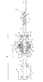
- FIG. 2 is a partial cross-sectional view showing an internal configuration of the single-axis robot of FIG. 1.
- the fragmentary sectional view which expands and shows the periphery of a coupling unit.
- the fragmentary sectional view which expands and shows the periphery of a coupling unit.
- the front perspective view of a coupling unit The rear perspective view of a coupling unit.
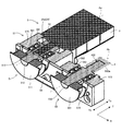
- the perspective view which shows the external appearance structure of the 2nd state of the single axis robot which concerns on this invention.
- FIG. 8 is a partial cross-sectional view showing an internal configuration of the single-axis robot of FIG. 7.
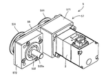
- the front perspective view which shows the external appearance structure of a power transmission device and a motor.
- the rear perspective view which shows the external appearance structure of a power transmission device and a motor.
- the rear perspective view which shows the external appearance structure of a power transmission device.
- the fragmentary sectional view which shows typically the structure of a power transmission device and a motor.
- FIG. 1 is a perspective view showing an external configuration of a first state of a single-axis robot according to the present invention.
- FIG. 2 is a partial cross-sectional view showing the internal configuration of the single-axis robot of FIG. In the first state shown in FIGS. 1 and 2, the rotation of the output shaft 21 of the motor 2 is transmitted to the screw shaft 31 of the ball screw 3 in a series system (straight system).
- the single-axis robot 1 includes a rectangular housing 11 that is long in the X direction, and a slider 13 that reciprocates in the X direction along the housing 11. Further, the single-axis robot 1 includes a motor 2 attached to the end of the housing 11 in the X direction, and the motor 2 generates a driving force for moving the slider 13.
- the single-axis robot 1 includes a ball screw 3 and a coupling unit 4 that couples the ball screw 3 to the motor 2 inside the housing 11.
- the ball screw 3 includes a screw shaft 31 that is arranged parallel to the X direction and is rotatable, and a nut 32 that is screwed onto the screw shaft 31, and the slider 13 is attached to the nut 32.
- the motor 2 has a rotatable output shaft 21 disposed in parallel with the X direction.
- the screw shaft 31 of the ball screw 3 is coupled to the output shaft 21 of the motor 2 by the coupling unit 4. Therefore, when the motor 2 rotates the output shaft 21, the screw shaft 31 of the ball screw 3 rotates with the output shaft 21, and the nut 32 moves in the X direction with the slider 13.
- FIG. 3 and 4 are partial cross-sectional views showing the periphery of the coupling unit in an enlarged manner.
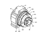
- FIG. 5 is a front perspective view of the coupling unit
- FIG. 6 is a rear perspective view of the coupling unit.
- 3 shows a state in which the output shaft 21 of the motor 2 and the screw shaft 31 of the ball screw 3 are coupled by the coupling unit 4.
- the configurations of the motor 2, the ball screw 3, and the coupling unit 4 are shown. Is shown exploded in the X direction, that is, in the thrust direction T of the output shaft 21 and the screw shaft 31. 3 and 4, the internal configuration of the motor 2 is indicated by a broken line, and the housing 11 partially shown in FIG. 3 is omitted in FIG. 4.
- the motor 2 includes two radial bearings 22 that support the output shaft 21 from the radial direction R, an electric circuit (not shown) for rotating the output shaft 21, and a housing 23 that accommodates these radial bearings 22 and the like.
- a shaft end 21a (output shaft end 21a) of the output shaft 21 protrudes from the housing 22 to one side Ta (that is, the screw shaft 31 side) in the thrust direction T.
- the shaft end 21a of the output shaft 21 has a cylindrical shape, and the outer peripheral surface of the shaft end 21a of the output shaft 21 is smoothly formed in parallel to the thrust direction T and has no step.
- the corner of the shaft end 21a is chamfered.
- the screw shaft 31 of the ball screw 3 includes a screw portion 31a in which a screw thread 310 is provided and the nut 32 is screwed, and a shaft end 31b (screw shaft end 31b) provided adjacent to the screw portion 31a.
- a shaft end 31b extends from the screw portion 31a to the other side Tb in the thrust direction T (that is, the output shaft 21 side and the opposite side of the one side Ta).
- the shaft end 31b has a cylindrical shape, and the outer peripheral surface of the shaft end 31b of the screw shaft 31 is smoothly formed in parallel with the thrust direction T and has no step. The corner of the shaft end 31b is chamfered.
- the coupling unit 4 couples the shaft end 21a of the output shaft 21 and the shaft end 31b of the screw shaft 31 facing each other side by side in the thrust direction T. That is, the output shaft 21 and the screw shaft 31 arranged in series in the thrust direction T are coupled by the coupling unit 4 (series method). In other words, the output shaft 21 and the screw shaft 31 are arranged on the same axis A. ing.
- the axis A is a virtual straight line parallel to the thrust direction T.
- the coupling unit 4 has a shaft 41 extending in the thrust direction T.
- the shaft 41 is a rigid body made of metal or the like, and has a rotationally symmetric shape with respect to an axis of symmetry parallel to the thrust direction T.
- the shaft 41 has a flange 411 formed at an end portion on one side Ta in the thrust direction T and a screw portion 412 formed at an end portion on the other side Tb in the thrust direction T.
- the shaft 41 is formed with a hollow portion 42 penetrating in the thrust direction T.
- the hollow portion 42 includes a first insertion hole 421 that opens to one side Ta in the thrust direction T and the other side in the thrust direction T. And a second insertion hole 422 that opens to Tb.
- Each of the first insertion hole 421 and the second insertion hole 422 has a concentric cylindrical shape extending in the thrust direction T, and the space between the first insertion hole 421 and the second insertion hole 422 is between the shaft 41 and the shaft 41.
- An annular protrusion 423 that protrudes inward from the inner wall of the hollow portion 42 is formed.
- the first insertion hole 421 has a shape corresponding to the shape of the shaft end 31 b (first shaft end) of the screw shaft 31.
- the first insertion hole 421 is provided on the shaft end 31 b of the screw shaft 31. It has a cylindrical shape with a diameter equal to the diameter of the cylindrical shape. That is, the inner diameter of the first insertion hole 421 is equal to the outer diameter of the shaft end 31 b of the screw shaft 31. Therefore, the shaft end 31 b of the screw shaft 31 can be fitted into the first insertion hole 421 of the shaft 41 from the one side Ta in the thrust direction T without any play, and the shaft 41 is a screw fitted into the first insertion hole 421.
- the shaft end 31b of the shaft 31 is restrained in the radial direction R.
- the second insertion hole 422 has a shape corresponding to the shape of the shaft end 21 a (second shaft end) of the output shaft 21, and in this example, the second insertion hole 422 has the shaft end 21 a of the output shaft 21. It has a cylindrical shape with a diameter equal to the diameter of the cylindrical shape. That is, the inner diameter of the second insertion hole 422 is equal to the outer diameter of the shaft end 21 a of the output shaft 21. Therefore, the shaft end 21a of the output shaft 21 can be fitted into the second fitting hole 422 of the shaft 41 from the other side Tb in the thrust direction T without any play, and the shaft 41 is fitted into the second fitting hole 422. The shaft end 21a of the shaft 21 is restrained in the radial direction R.
- the screw shaft 31 whose shaft end 31 b is fitted in the first insertion hole 421 and the output shaft 21 whose shaft end 21 a is fitted in the second insertion hole 422 are both in the radial direction R by the shaft 41. Be bound.
- the shaft 41 positions the shaft end 31b of the screw shaft 31 and the shaft end 21a of the output shaft 21 with each other in the radial direction R in a state in which the respective center lines coincide with each other.
- the hollow portion 42 of the shaft 41 has a tapered hole 424 extending from the first insertion hole 421 to one side Ta in the thrust direction T.
- the taper hole 424 has a truncated cone shape whose diameter increases toward the one side Ta in the thrust direction T.
- the taper hole 424 includes a shaft end 31 b of the screw shaft 31 fitted in the first insertion hole 421, and the taper hole 424.
- a gap 425 is formed between the inner wall of the shaft 41 to be defined.
- the coupling unit 4 has a sparing 43 inserted into the gap 425.
- the sparing 43 has a rotationally symmetric shape with respect to an axis of symmetry parallel to the thrust direction T.
- a hollow portion 431 penetrating in the thrust direction T is formed in the sparing 43.
- the hollow portion 431 has a cylindrical shape having a diameter equal to the cylindrical shape of the shaft end 31 b of the screw shaft 31, and the shaft end 31 b of the screw shaft 31 is fitted into the hollow portion 431 of the sparing 43.
- the end of the other side Tb of the sparing 43 has a frustoconical outer shape whose diameter decreases toward the other side Tb in the thrust direction T.
- the peripheral edge portion of the end portion on the other side Tb of the sparing 43 has a wedge shape, and functions as an insertion portion 432 (wedge) that can be inserted into and removed from the gap 425. Further, the sparing 43 has a flange 433 at the end of one side Ta.
- the insertion portion 432 of the sparing 43 When the insertion portion 432 of the sparing 43 is inserted into the gap 425 between the screw shaft 31 and the shaft 41, it is pressed against each of the inner wall of the tapered hole 424 of the shaft 41 and the outer periphery of the shaft end 31 b of the screw shaft 31. Is done. As a result, the shaft end 31 b of the screw shaft 31 fitted in the first insertion hole 421 is fastened to the shaft 41. Further, the flange 433 of the sparing 43 is fastened to the flange 411 of the shaft 41 by a screw 434. Thus, the screw shaft 31 can be firmly fixed to the shaft 41 by the sparing 43.
- an O-ring 44 made of rubber is disposed inside the first insertion hole 421 of the shaft 41, and the shaft end 31 b of the screw shaft 31 is connected to the annular protrusion 423 of the shaft 41 via the O-ring 44. It is hit by. Therefore, the O-ring 44 is elastically deformed as the shaft end 31b of the screw shaft 31 is drawn into the first insertion hole 421 as the sparging 43 is inserted. Thus, the movement of the shaft end 31b of the screw shaft 31 is not hindered by passing through the O-ring 44, and the fastening strength between the shaft end 31b of the screw shaft 31 and the shaft 41 is improved. ing.
- the coupling unit 4 has a split fastening mechanism 45 provided on the other side Tb of the shaft 41.
- the cleaving mechanism 45 is formed integrally with the shaft 41 and is provided at the end of the other side Tb of the shaft 41.
- the cleaving mechanism 45 includes two semicircular members 451, screws 452 that fasten the two semicircular members 451, and pins that attach the two semicircular members 451 to each other. 453. These two semicircular members 451 are arranged so as to form a circle, and a hollow portion 454 is formed between them.
- the hollow portion 454 of the cleaving mechanism 45 has a substantially cylindrical shape penetrating in the thrust direction T, and is aligned with the second insertion hole 422 of the shaft 41 in the thrust direction T.
- the coupling unit 4 has two thrust bearings 46 that support the shaft 41 in the thrust direction T, and a base 47 that supports the thrust bearing 46.
- the thrust bearing 46 has a housing washer 461 fixed to the base 47 and an axial washer 462 that supports the shaft 41.
- the base 47 is fixed to the housing 11 of the single-axis robot 1 by screws 470 and functions to support the shaft 41 with respect to the housing 11 via the thrust bearing 46.
- a shaft hole 471 penetrating in the thrust direction T is formed in the base 47.
- the diameter of the shaft hole 471 is slightly larger than the diameter of the outer periphery 41 a of the shaft 41 (the outer periphery of the cylindrical portion 41 b between the flange 411 and the screw portion 412), and the shaft 41 fits into the shaft hole 471 of the base 47.
- the outer periphery 41 a of the cylindrical portion 41 b of the shaft 41 has a shape corresponding to the inner periphery of the axial washer 462 of each thrust bearing 46.
- the outer circumference 41 a of the cylindrical portion 41 b of the sparing 43 is formed to have a diameter equal to the inner circumference of the axial raceway 462 of each thrust bearing 46, and the shaft 41 fits inside each thrust bearing 46.
- the diameter of the housing washer 461 of each thrust bearing 46 is equal to or slightly larger than the diameter of the outer periphery 41a of the cylindrical portion 41b of the sparing 43.
- the two thrust bearings 46 are arranged so as to sandwich the peripheral edge portion 472 of the shaft hole 471 of the base 47 from the thrust direction T.
- a nut 481 is attached to the screw portion 412 of the shaft 41 with a washer 482 (chrysanthemum) sandwiched between the two thrust bearings 46 and the thrust bearing 46 on the other side Tb.
- the washer 482, the thrust bearing 46, the peripheral edge 472 of the base 47, and the thrust bearing 46 arranged in the thrust direction T are sandwiched between the flange 411 and the nut 481. Therefore, when the nut 481 is screwed into the screw portion 412 of the shaft 41, the housing washer 461 of each thrust bearing 46 is pressed against the peripheral portion 472 of the base 47, and the shaft washer 462 of the thrust bearing 46 on the one side Ta is The shaft washer 462 of the thrust bearing 46 on the other side Tb is pressed through a washer 482 to a nut 481 that is screwed into the shaft 41. As a result, the housing washer 461 of each thrust bearing 46 is fixed to the base 47, and the axial washer 462 of the thrust bearing 46 is fixed to the shaft 41.
- the support in the thrust direction T of the screw shaft 31 and the output shaft 21 coupled by the coupling unit 4 is mainly realized by the thrust bearing 46. Further, the support in the radial direction R of the screw shaft 31 and the output shaft 21 is mainly realized by the radial bearing 22 of the motor 2.
- FIG. 7 is a perspective view showing an external configuration of the second state of the single-axis robot according to the present invention.
- FIG. 8 is a partial cross-sectional view showing the internal configuration of the single-axis robot of FIG.
- the rotation of the output shaft 21 of the motor 2 is transmitted to the screw shaft 31 of the ball screw 3 in a parallel manner (folding manner).
- the difference from the first state will be mainly described, and portions common to the first state will be denoted by corresponding reference numerals and description thereof will be omitted.
- the single-axis robot 1 includes a power transmission device 5 that transmits the rotation of the output shaft 21 to the screw shaft 31.
- FIG. 9 is a front perspective view showing the external configuration of the power transmission device and the motor.
- FIG. 10 is a rear perspective view showing the external configuration of the power transmission device and the motor.
- FIG. 11 is a rear perspective view showing an external configuration of the power transmission device.
- FIG. 12 is a partial cross-sectional view schematically showing the configuration of the power transmission device and the motor. In FIG. 12, a part of the coupling unit 4 (around the second insertion hole 422) is schematically illustrated.
- the power transmission device 5 includes a first rotating part 51 attached to the output shaft 21 of the motor 2, a second rotating part 53 attached to the screw shaft 31 of the ball screw 3, and the first rotating part 51 and the second rotating part 53. And a belt 55 wound around. Furthermore, the power transmission device 5 includes a housing 57 that rotatably supports the first rotating portion 51 and the second rotating portion 53.
- the housing 57 includes a first support portion 571 that supports the first rotating portion 51, a second support portion 572 that supports the second rotating portion 53, and a first support portion 571 and a second support portion 572. And a plate 573 to be fixed.
- the first rotating unit 51 includes a pulley 511 and a rotating shaft 512 (first rotating shaft) fixed to the pulley 511.
- the rotation shaft 512 is provided so as to protrude from the center of the pulley 511 toward the one side Ta in the thrust direction T.
- the rotation shaft 512 and the pulley 511 can rotate around the same center line parallel to the thrust direction T.
- two radial bearings 581 are mounted in the thrust direction T inside the first support portion 571, and the rotating shaft 512 is supported in the radial direction R by these radial bearings 581.
- the inner diameter of the inner ring of each radial bearing 581 is equal to the outer diameter of the rotating shaft 512
- the rotating shaft 512 is fitted and attached to the inner ring of each radial bearing 581
- the outer ring of each radial bearing 581 is the first. It is attached to the support portion 571.
- the rotation shaft 512 is provided with a fitting hole 513 in the thrust direction T that opens to one side Ta in the thrust direction T.
- the insertion hole 513 has a cylindrical shape with a diameter equal to the cylindrical shape of the shaft end 21 a of the output shaft 21. That is, the inner diameter of the fitting hole 513 is equal to the outer diameter of the shaft end 21 a of the output shaft 21. Therefore, the shaft end 21 a of the output shaft 21 can be fitted into the fitting hole 513 of the rotating shaft 512 without play from the one side Ta in the thrust direction T, and the shaft end 21 a of the output shaft 21 fitted in the fitting hole 513.
- the rotating shaft 512 is positioned relative to each other in the radial direction R in a state where the respective center lines coincide with each other.
- the power transmission device 5 has a cleaving mechanism 52 provided on one side Ta of the rotating shaft 512.
- the cleaving mechanism 52 is formed integrally with the rotating shaft 512 and thus provided at the end portion of the one side Ta of the rotating shaft 512.
- the cleaving mechanism 52 includes an annular member 521 that is partially cut away, and a screw 522 that changes the width of the gap between the cutouts of the annular member 521.
- a hollow portion 523 is formed inside the annular member 521.
- the hollow portion 523 of the cleaving mechanism 52 has a substantially cylindrical shape penetrating in the thrust direction T, and is aligned with the insertion hole 513 of the rotating shaft 512 in the thrust direction T.
- the inner periphery of the annular member 521 is the shaft end 21 a of the output shaft 21. Is pressed against the outer periphery of the plate (clamping).
- the annular member 521 sandwiches the shaft end 21 a of the output shaft 21, so that the shaft end 21 a of the output shaft 21 is fastened to the rotating shaft 512.
- the output shaft 21 can be firmly fixed to the rotating shaft 512 by the splitting mechanism 52.
- the second rotating unit 53 includes a pulley 531 and a rotating shaft 532 (second rotating shaft) fixed to the pulley 531.
- the rotation shaft 532 protrudes from the center of the pulley 531 to one side Ta in the thrust direction T.
- the rotation shaft 532 and the pulley 531 can rotate around the same center line parallel to the thrust direction T and are concentric. It has the shape of
- two radial bearings 582 are attached in the thrust direction T inside the second support portion 572, and the rotating shaft 532 is supported in the radial direction R by these radial bearings 582.
- the inner diameter of the inner ring of the radial bearing 582 is equal to the outer diameter of the rotating shaft 532, the rotating shaft 532 is fitted and attached to the inner ring of each radial bearing 582, and the outer ring of each radial bearing 582 is supported by the second ring. It is attached to the part 572.
- the rotating shaft 532 has a protruding end 532a that protrudes from the second support portion 572 to the one side Ta in the thrust direction T.
- the rotating shaft 532 has a cylindrical shape with a diameter equal to the cylindrical diameter of the shaft end 21 a of the output shaft 21. That is, the outer diameter of the rotating shaft 532 is equal to the outer diameter of the shaft end 21 a of the output shaft 21. Therefore, instead of the shaft end 21 a of the output shaft 21 of the motor 2, the protruding end 532 a of the rotating shaft 532 can be fastened to the coupling unit 4.
- the protruding end 532a of the rotating shaft 532 has a shape corresponding to the shape of the second insertion hole 422.
- the protruding end 532a has a diameter equal to the diameter of the cylindrical shape of the second insertion hole 422. It has a cylindrical shape. That is, the outer diameter of the protruding end 532a is equal to the inner diameter of the second insertion hole 422. Therefore, the protruding end 532a of the rotating shaft 532 can be fitted into the second fitting hole 422 of the shaft 41 from the other side Tb in the thrust direction T without any play, and the shaft 41 is fitted into the second fitting hole 422.
- the protruding end 532a of the shaft 532 is restrained in the radial direction R.
- the endless belt 55 is stretched over the pulley 511 of the first rotating part 51 and the pulley 531 of the second rotating part 53, and the rotation of the first rotating part 51 is transmitted to the second rotating part 53.
- the tension of the belt 55 is adjusted in advance when the power transmission device 5 is manufactured and shipped. For example, this tension adjustment can be performed by changing the position where the first support portion 571 and the second support portion 572 are attached to the plate 573 and adjusting the distance between the pulley 511 and the pulley 531.
- the power transmission device 5 couples the output shaft 21 of the motor 2 and the screw shaft 31 of the ball screw 3 arranged in parallel.
- the power transmission device 5 transmits the rotation of the output shaft 21 of the motor 2 to the screw shaft 31 of the ball screw 3. That is, when the first rotating part 51 of the power transmission device 5 rotates with the rotation of the output shaft 21 of the motor 2, the belt 55 rotates with the first rotating part 51 and rotates the second rotating part 53. . As a result, the screw shaft 31 of the ball screw 3 fastened to the second rotating portion 53 rotates.
- the first rotating part 51 in which the fitting hole 513 into which the output shaft 21 of the motor 2 can be fitted opens, and the second rotating part 53 in which the rotating shaft 532 protrudes.
- Any one of the output shaft 21 of the motor 2 and the rotating shaft 532 of the power transmission device 5 can be selectively fastened to the coupling unit 4 fastened to the screw shaft 31 of the ball screw 3.
- this coupling unit 4 is provided with a first insertion hole 421 that opens to one side Ta in the thrust direction T and a second insertion hole 422 that opens to the other side Tb in the thrust direction T. It is fastened to the screw shaft 31 of the ball screw 3 fitted in 421. Then, in a state where the output shaft 21 arranged toward the other side Tb in the thrust direction T and the ball screw 3 are arranged in parallel, the output shaft 21 fitted in the fitting hole 513 facing the one side Ta in the thrust direction T. Is fastened to the first rotating portion 51, whereby the output shaft 21 is fixed to the first rotating portion 51.
- the coupling unit 4 is fixed to the second rotating portion 53 by fastening the rotating shaft 532 fitted in the second fitting hole 422 so as to face the one side Ta in the thrust direction T.
- the rotation of the output shaft 21 of the motor 2 can be transmitted to the screw shaft 31 of the ball screw 3 in a parallel manner (first state).
- the output shaft 21 fitted in the second insertion hole 422 is provided in a state where the power transmission device 5 is detached from each of the output shaft 21 and the coupling unit 4 and the output shaft 21 and the screw shaft 31 are arranged in series.
- the coupling unit 4 is fixed to the output shaft 21 by being fastened to the coupling unit 4.
- the 1st rotation part 51, the 2nd rotation part 53, and the belt 55 are assembled as one power transmission device 5, and are unitized. Therefore, if the power transmission device 5 is assembled with the tension of the belt 55 adjusted at the time of production of the power transmission device 5, it is necessary to readjust the tension of the belt 55 when switching from the serial system to the parallel system thereafter. No.
- the power transmission device 5 includes a radial bearing 581 that supports the first rotating portion 51 in the radial direction R. As a result, the first rotating portion 51 can be firmly supported in the radial direction R.
- the power transmission device 5 includes a radial bearing 581 that supports the second rotating portion 53 in the radial direction R. As a result, the second rotating portion 53 can be firmly supported in the radial direction R.
- the single-axis robot 1 corresponds to an example of the “robot” of the present invention
- the power transmission system 6 (FIG. 8) composed of the coupling unit 4 and the power transmission device 5 is the main robot.
- the power transmission device 5 corresponds to an example of the “power transmission device” of the present invention
- the first rotating portion 51 corresponds to an example of the “first rotating portion” of the present invention.
- the insertion hole 513 corresponds to an example of the “insertion hole” of the present invention
- the second rotation part 53 corresponds to an example of the “second rotation part” of the present invention
- the rotation shaft 532 corresponds to the “protrusion” of the present invention.
- the belt 55 corresponds to an example of “transmission part” and “belt” of the present invention
- the ball screw 3 corresponds to an example of “ball screw” of the present invention
- the screw shaft 31 corresponds to an example of “shaft”. It corresponds to an example of “screw shaft”, and the nut 32 and the slider 13 cooperate.
- the coupling unit 4 corresponds to an example of the “coupling device” of the present invention
- the first insertion hole 421 corresponds to an example of the “first insertion hole” of the present invention.
- the second insertion hole 422 corresponds to an example of the “second insertion hole” of the present invention
- the motor 2 corresponds to an example of the “motor” of the present invention
- the output shaft 21 corresponds to the “output shaft” of the present invention.
- the radial bearing 581 corresponds to an example of the “first radial bearing” of the present invention
- the radial bearing 582 corresponds to an example of the “second radial bearing” of the present invention
- the axis Aa and the axis Ab are
- the invention corresponds to an example of “different axes” of the invention
- the axis A corresponds to an example of “same axis” of the invention.
- the coupling unit 4 and the power transmission device 5 described above may be used to transmit the rotation of the output shaft 21 of the motor 2 to the screw shaft 31 of the ball screw 3 in a multi-axis robot other than the single-axis robot 1. good.
- the specific mechanism for fastening the shaft end 21a of the output shaft 21 to the first rotating portion 51 is not limited to the split fastening mechanism 52, and may be another mechanism such as sparing.
- the specific mechanism for fixing the screw shaft 31 to the shaft 41 is not limited to the sparing 43, but may be another mechanism such as a split tightening mechanism.
- the specific mechanism for fixing the output shaft 21 to the shaft 41 is not limited to the cleaving mechanism 45 but may be other mechanisms such as sparing.
- the configuration for transmitting the rotation of the first rotating unit 51 to the second rotating unit 53 is not limited to the belt 55, and may be another mechanism such as a gear.
- the specific configuration of the coupling device that is fastened to the screw shaft 31 of the ball screw 3 and that is selectively fastened to the output shaft 21 of the motor 2 or the rotating shaft 532 of the power transmission device 5 is the above-described coupling unit. It is not limited to four. Therefore, for example, the coupling device may be configured by a leaf spring coupling or the like.
- the robot may be configured so that the transmission unit is an endless belt that is stretched between the first rotating unit and the second rotating unit.
- the first rotating part, the second rotating part, and the belt are assembled as one power transmission device. Therefore, if the power transmission device is assembled with the belt tension adjusted during production of the power transmission device, there is no need to readjust the belt tension when switching from the serial system to the parallel system thereafter.
- the power transmission device may be configured such that the robot has a first radial bearing that supports the first rotating portion in the radial direction. Thereby, the first rotating part can be firmly supported in the radial direction.
- the power transmission device may be configured such that the robot has a second radial bearing that supports the second rotating portion in the radial direction. Thereby, the second rotating part can be firmly supported in the radial direction.
- This invention can be applied to all techniques for transmitting the rotation of the output shaft of a motor to the screw shaft of a ball screw.
Landscapes
- Engineering & Computer Science (AREA)
- Robotics (AREA)
- Mechanical Engineering (AREA)
- Transmission Devices (AREA)
- Manipulator (AREA)
- Connection Of Motors, Electrical Generators, Mechanical Devices, And The Like (AREA)
Abstract
ネジ軸を有するボールネジと、第1嵌入孔と、第2嵌入孔とが設けられ、第1嵌入孔に嵌め込まれたネジ軸に締結された結合装置と、出力軸を回転させるモーターと、出力軸を嵌め込み可能な第3嵌入孔が開口する第1回転部と、第2嵌入孔に嵌め込み可能な突出軸が突出する第2回転部と、第1回転部の回転を第2回転部に伝達する伝達部とを有する動力伝達装置とを備え、出力軸とネジ軸とが異なる軸線上に配置された状態において、スラスト方向の一方側を向く第3嵌入孔に嵌め込まれた出力軸が第1回転部に締結されることで第1回転部に固定されるとともに、突出軸が第2嵌入孔に嵌め込まれて結合装置に締結されることで、結合装置が第2回転部に固定される一方、動力伝達装置が出力軸および結合装置から取り外されて出力軸とネジ軸が同じ軸線上に配置された状態において、出力軸が第2嵌入孔に嵌め込まれて結合装置に締結されることで、結合装置が出力軸に固定される。
Description
本発明は、ボールネジのネジ軸にモーターの出力軸の回転を伝達する技術に関するものである。
単軸ロボットのような産業用ロボットでは、ボールネジをモーターで駆動することでボールネジに螺合する移動体を移動させる直動機構が一般に用いられる。また、モーターの出力軸の回転をボールネジのネジ軸に伝達する方式としては二通りが存在する。一つは、直列に配列された出力軸とネジ軸とをカップリングで結合する直列方式であり、もう一つは、特許文献1に記載されているように、並列に配列された出力軸とネジ軸とを結合する並列方式である。具体的には、後者の方式は、出力軸の軸端に取り付けられたプーリーと、ネジ軸の軸端に取り付けられたプーリーと、これらプーリーに掛け渡されたタイミングベルトとを用いて、出力軸の回転をネジ軸に伝達する。
ところで、並列方式では、ロボットの幅が広くなる代わりにロボットを短尺化できる一方、直列方式では、ロボットが長尺化する代わりにロボットの幅を抑えられる。このように両方式はメリットおよびデメリットにおいてそれぞれ異なる。そこで、ロボットの設置環境等に応じて、直列方式と並列方式とを簡便に切り換えられる技術が求められていた。
本発明は上記課題に鑑みてなされたものであり、モーターの出力軸の回転をボールネジのネジ軸に伝達する方式を直列方式と並列方式との間で簡便に切り換えることを可能とする技術の提供を目的とする。
本発明に係るロボットは、回転可能なネジ軸を有するボールネジと、ネジ軸に螺合してネジ軸の回転に伴って移動する移動体と、スラスト方向の一方側へ開口する第1嵌入孔と、スラスト方向の他方側へ開口する第2嵌入孔とが設けられ、第1嵌入孔に嵌め込まれたネジ軸に締結された結合装置と、回転可能な出力軸を有し、出力軸を回転させるモーターと、出力軸を嵌め込み可能な第3嵌入孔が開口する第1回転部と、第2嵌入孔に嵌め込み可能な突出軸を有する第2回転部と、第1回転部の回転を第2回転部に伝達する伝達部とを有する動力伝達装置とを備え、スラスト方向の他方側に向けて配置された出力軸とネジ軸とが異なる軸線上に配置された状態において、スラスト方向の一方側を向く第3嵌入孔に嵌め込まれた出力軸が第1回転部に締結されることで第1回転部に固定されるとともに、スラスト方向の一方側を向いて突出軸が第2嵌入孔に嵌め込まれ結合装置に締結されることで、結合装置が第2回転部に固定される一方、動力伝達装置が出力軸および結合装置から取り外されてモーターの出力軸とネジ軸が同じ軸線上に配置された状態において、出力軸が第2嵌入孔に嵌め込まれ結合装置に締結されることで、結合装置が出力軸に固定される。
本発明に係る動力伝達装置は、モーターの出力軸を嵌め込み可能な第3嵌入孔が開口する第1回転部と、スラスト方向の一方側へ開口する第1嵌入孔と、スラスト方向の他方側へ開口する第2嵌入孔とが設けられ、第1嵌入孔に嵌め込まれたボールネジのネジ軸に締結されるとともに、ネジ軸と同じ軸線上に配置されて第2嵌入孔に嵌め込まれた出力軸に締結可能な結合装置の第2嵌入孔に嵌め込み可能な突出軸を有する第2回転部と、第1回転部の回転を第2回転部に伝達する伝達部とを備え、スラスト方向の他方側に向けて配置された出力軸とネジ軸とが異なる軸線上に配置された状態において、スラスト方向の一方側を向く第3嵌入孔に嵌め込まれた出力軸が、第1回転部に締結されることで第1回転部に固定されるとともに、スラスト方向の一方側を向いて突出軸が結合装置の第2嵌入孔に嵌め込まれ締結されることで、結合装置が第2回転部に固定される。
本発明に係る動力伝達システムは、スラスト方向の一方側へ開口する第1嵌入孔と、スラスト方向の他方側へ開口する第2嵌入孔とが設けられ、第1嵌入孔に嵌め込まれたボールネジのネジ軸に締結可能な結合装置と、モーターの出力軸を嵌め込み可能な第3嵌入孔が開口する第1回転部と、第2嵌入孔に嵌め込み可能な突出軸が突出する第2回転部と、第1回転部の回転を第2回転部に伝達する伝達部とを有する動力伝達装置とを備え、スラスト方向の他方側に向けて配置された出力軸とネジ軸とが異なる軸線上に配置された状態において、スラスト方向の一方側を向く第3嵌入孔に嵌め込まれた出力軸が第1回転部に締結されることで出力軸が第1回転部に固定されるとともに、スラスト方向の一方側を向いて第2嵌入孔に嵌め込まれた突出軸が結合装置に締結されることで結合装置が第2回転部に固定される一方、動力伝達装置が出力軸および結合装置から取り外されてモーターの出力軸とネジ軸が同じ軸線上に配置された状態において、第2嵌入孔に嵌め込まれた出力軸が結合装置に締結されることで、結合装置が出力軸に固定される動力伝達システム。
このように構成された本発明(ロボット、動力伝達装置、動力伝達システム)では、モーターの出力軸を嵌め込み可能な第3嵌入孔が開口する第1回転部と、突出軸が突出する第2回転部と、第1回転部の回転を第2回転部に伝達する伝達部とが設けられている。そして、モーターの出力軸および第2回転部の突出軸のいずれかが選択的に、ボールネジのネジ軸に締結された結合装置に締結可能となっている。
つまり、この結合装置は、スラスト方向の一方側へ開口する第1嵌入孔と、スラスト方向の他方側へ開口する第2嵌入孔とが設けられ、第1嵌入孔に嵌め込まれたボールネジのネジ軸に締結される。そして、スラスト方向の他方側に向けて配置された出力軸とネジ軸とが異なる軸線上に配置された(すなわち、並列に配置された)状態において、スラスト方向の一方側を向く第3嵌入孔に嵌め込まれた出力軸が第1回転部に締結されることで出力軸が第1回転部に固定されるとともに、スラスト方向の一方側を向いて第2嵌入孔に嵌め込まれた突出軸が結合装置に締結されることで結合装置が第2回転部に固定される。これによって、モーターの出力軸の回転をボールネジのネジ軸に並列方式で伝達することができる。また、動力伝達装置が出力軸および結合装置から取り外されて出力軸とネジ軸が同じ軸線上に配置された(すなわち、直列に配置された)状態において、第2嵌入孔に嵌め込まれた出力軸が結合装置に締結されることで結合装置が出力軸に固定される。これによって、モーターの出力軸の回転をボールネジのネジ軸に直列方式で伝達することができる。こうして、モーターの出力軸の回転をボールネジのネジ軸に伝達する方式を直列方式と並列方式との間で簡便に切り換えることが可能となっている。
本発明では、モーターの出力軸の回転をボールネジのネジ軸に伝達する方式を直列方式と並列方式との間で簡便に切り換えることが可能となっている。
図1は本発明に係る単軸ロボットの第1状態の外観構成を示す斜視図である。図2は図1の単軸ロボットの内部構成を示す部分断面図である。図1および図2に示す第1状態は、モーター2の出力軸21の回転をボールネジ3のネジ軸31に直列方式(ストレート方式)で伝達する。
この単軸ロボット1は、X方向に長尺な矩形状のハウジング11と、ハウジング11に沿ってX方向に往復移動するスライダー13とを備える。さらに、単軸ロボット1は、ハウジング11のX方向の端に取り付けられたモーター2を備え、モーター2がスライダー13を移動させるための駆動力を発生する。
つまり、図2に示すように、単軸ロボット1は、ボールネジ3と、このボールネジ3をモーター2に結合するカップリングユニット4とをハウジング11の内部に備える。ボールネジ3は、X方向に平行に配置されて回転可能なネジ軸31と、ネジ軸31に螺合するナット32とを有し、スライダー13がナット32に取り付けられている。また、モーター2はX方向に平行に配置された回転可能な出力軸21を有する。そして、ボールネジ3のネジ軸31がモーター2の出力軸21にカップリングユニット4により結合されている。したがって、モーター2がその出力軸21を回転させると、ボールネジ3のネジ軸31が出力軸21に伴って回転し、ナット32がスライダー13を伴ってX方向に移動する。
図3および図4はカップリングユニットの周辺を拡大して示す部分断面図である。図5はカップリングユニットの前方斜視図であり、図6はカップリングユニットの後方斜視図である。なお、図3では、モーター2の出力軸21とボールネジ3のネジ軸31とがカップリングユニット4により結合された状態が示され、図4では、モーター2、ボールネジ3およびカップリングユニット4の構成をX方向、すなわち出力軸21およびネジ軸31のスラスト方向Tに分解した状態が示されている。また、図3および図4ではモーター2の内部構成が破線で示されるとともに、図3では部分的に示されているハウジング11が図4では省略されている。
モーター2は、出力軸21をラジアル方向Rから支持する2個のラジアルベアリング22と、出力軸21を回転させるための電気回路(図示省略)やこれらラジアルベアリング22等を収容するハウジング23とを有する。出力軸21の軸端21a(出力軸端21a)は、ハウジング22からスラスト方向Tの一方側Ta(すなわち、ネジ軸31側)へ突出している。この出力軸21の軸端21aは円筒形状を有し、出力軸21の軸端21aの外周面はスラスト方向Tに平行に滑らかに形成されており段差を有さない。なお、軸端21aの角には面取りが施されている。
ボールネジ3のネジ軸31は、ネジ山310が設けられてナット32が螺合するネジ部31aと、ネジ部31aに隣接して設けられた軸端31b(ネジ軸端31b)とを有し、ネジ部31aからスラスト方向Tの他方側Tb(すなわち、出力軸21側であるとともに一方側Taの逆側)へ軸端31bが延設されている。この軸端31bは円筒形状を有し、ネジ軸31の軸端31bの外周面は、スラスト方向Tに平行に滑らかに形成されており段差を有さない。なお、軸端31bの角には面取りが施されている。
そして、スラスト方向Tに並んで互いに対向する出力軸21の軸端21aとネジ軸31の軸端31bとを、カップリングユニット4が結合する。つまり、スラスト方向Tに直列に並ぶ出力軸21とネジ軸31とがカップリングユニット4によって結合され(直列方式)、換言すれば、出力軸21とネジ軸31とは同じ軸線A上に配置されている。ここで、軸線Aはスラスト方向Tに平行な仮想直線である。このカップリングユニット4は、スラスト方向Tに延設されたシャフト41を有する。シャフト41は、金属等で作成された剛性体であり、スラスト方向Tに平行な対称軸に対して回転対称な形状を有する。このシャフト41は、スラスト方向Tの一方側Taの端部に形成されたフランジ411と、スラスト方向Tの他方側Tbの端部に形成されたネジ部412とを有する。また、シャフト41には、スラスト方向Tに貫通する中空部42が形成されており、中空部42は、スラスト方向Tの一方側Taへ開口する第1嵌入孔421と、スラスト方向Tの他方側Tbへ開口する第2嵌入孔422とを有する。第1嵌入孔421と第2嵌入孔422とは、それぞれスラスト方向Tに延設された同心の円筒形状を有し、第1嵌入孔421と第2嵌入孔422との間は、シャフト41の中空部42の内壁から内側に突出する環状突起423が形成されている。
第1嵌入孔421はネジ軸31の軸端31b(第1軸端)の形状に応じた形状を有し、ここの例では、第1嵌入孔421は、ネジ軸31の軸端31bが有する円筒形状の径と等しい径の円筒形状を有する。つまり、第1嵌入孔421の内径は、ネジ軸31の軸端31bの外径に等しい。したがって、ネジ軸31の軸端31bはシャフト41の第1嵌入孔421にスラスト方向Tの一方側Taから遊びが無い状態で嵌入可能であり、シャフト41は第1嵌入孔421に嵌め込まれたネジ軸31の軸端31bをラジアル方向Rに拘束する。
第2嵌入孔422は出力軸21の軸端21a(第2軸端)の形状に応じた形状を有し、ここの例では、第2嵌入孔422は、出力軸21の軸端21aが有する円筒形状の径と等しい径の円筒形状を有する。つまり、第2嵌入孔422の内径は、出力軸21の軸端21aの外径に等しい。したがって、出力軸21の軸端21aはシャフト41の第2嵌入孔422にスラスト方向Tの他方側Tbから遊びが無い状態で嵌入可能であり、シャフト41は第2嵌入孔422に嵌め込まれた出力軸21の軸端21aをラジアル方向Rに拘束する。
つまり、その軸端31bが第1嵌入孔421に嵌め込まれたネジ軸31と、その軸端21aが第2嵌入孔422に嵌め込まれた出力軸21とは、いずれもシャフト41によってラジアル方向Rへ拘束される。このように、シャフト41は、ネジ軸31の軸端31bと出力軸21の軸端21aとをそれぞれの中心線を一致させた状態でラジアル方向Rに互いに位置決めする。
また、シャフト41の中空部42は、第1嵌入孔421からスラスト方向Tの一方側Taに延設されたテーパー孔424を有する。テーパー孔424は、スラスト方向Tの一方側Taに向かうに連れて径が増大する円錐台形状を有し、第1嵌入孔421に嵌め込まれたネジ軸31の軸端31bと、テーパー孔424を規定するシャフト41の内壁との間には隙間425が形成される。
そして、カップリングユニット4は、この隙間425に挿入されるシュパリング43を有する。シュパリング43は、スラスト方向Tに平行な対称軸に対して回転対称な形状を有する。このシュパリング43には、スラスト方向Tに貫通する中空部431が形成されている。中空部431は、ネジ軸31の軸端31bの円筒形状の径と等しい径の円筒形状を有し、シュパリング43の中空部431にネジ軸31の軸端31bが嵌入する。一方、シュパリング43の他方側Tbの端部は、スラスト方向Tの他方側Tbに向かうに連れて径が減少する円錐台形状の外形を有する。つまり、シュパリング43の他方側Tbの端部の周縁部は楔形を有し、隙間425に対して挿脱可能な挿入部432(楔)として機能する。また、シュパリング43は、フランジ433を一方側Taの端部に有する。
このシュパリング43の挿入部432は、ネジ軸31とシャフト41との間の隙間425に挿入されると、シャフト41のテーパー孔424の内壁とネジ軸31の軸端31bの外周とのそれぞれに押圧される。これによって、第1嵌入孔421に嵌め込まれたネジ軸31の軸端31bがシャフト41に締結される。さらに、シュパリング43のフランジ433がネジ434によってシャフト41のフランジ411に締結される。こうしてシュパリング43によってネジ軸31をシャフト41にしっかりと固定することが可能となっている。
ちなみに、シャフト41の第1嵌入孔421の内部には、ゴムで形成されたOリング44が配置されており、ネジ軸31の軸端31bは、Oリング44を介してシャフト41の環状突起423に突き当てられる。したがって、シュパリング43の挿入に伴ってネジ軸31の軸端31bが第1嵌入孔421に引き込まれるのに応じて、Oリング44が弾性変形する。このようにOリング44を介することで、ネジ軸31の軸端31bの移動が妨げられないように構成されており、ネジ軸31の軸端31bとシャフト41との締結強度の向上が図られている。
また、カップリングユニット4は、シャフト41の他方側Tbに設けられた割締め機構45を有する。この割締め機構45は、シャフト41と一体的に形成されることで、シャフト41の他方側Tbの端部に設けられている。割締め機構45は、図5に示すように、2個の半円部材451と、2個の半円部材451を相互に締結するネジ452と、2個の半円部材451を相互に取り付けるピン453とを有する。これら2個の半円部材451は円を構成するように配置され、それらの間に中空部454を形成する。割締め機構45の中空部454は、スラスト方向Tに貫通する略円筒形状を有し、シャフト41の第2嵌入孔422とスラスト方向Tに並ぶ。そして、出力軸21の軸端21aが割締め機構45の中空部454を介して第2嵌入孔422に嵌め込まれた状態でネジ452をねじ込むと、各半円部材451の内周が出力軸21の軸端21aの外周に押圧される(割締め)。こうして2個の半円部材451が出力軸21の軸端21aを挟み込むことで、出力軸21の軸端21aがシャフト41に締結される。これによって、割締め機構45によって出力軸21をシャフト41にしっかりと固定することが可能となっている。
このように、シャフト41によってラジアル方向Rに位置決めされたボールネジ3のネジ軸31とモーター2の出力軸21とがそれぞれシュパリング43と割締め機構45によりシャフト41に固定される。これによって、ボールネジ3のネジ軸31とモーター2の出力軸21とが結合される。
さらに、カップリングユニット4は、シャフト41をスラスト方向Tに支持する2個のスラストベアリング46と、スラストベアリング46を支持するベース47を有する。スラストベアリング46は、ベース47に固定されるハウジング軌道盤461と、シャフト41を支持する軸軌道盤462とを有する。また、ベース47は、ネジ470によって単軸ロボット1のハウジング11に固定されており、スラストベアリング46を介してシャフト41をハウジング11に対して支持する機能を果たす。
具体的には、ベース47には、スラスト方向Tに貫通するシャフト孔471が形成されている。シャフト孔471の径は、シャフト41の外周41a(フランジ411とネジ部412との間の円筒部41bの外周)の径より若干大きく、シャフト41はベース47のシャフト孔471に嵌まる。また、シャフト41の円筒部41bの外周41aは、各スラストベアリング46の軸軌道盤462の内周に応じた形状を有する。すなわち、シュパリング43の円筒部41bの外周41aは、各スラストベアリング46の軸軌道盤462の内周の径と等しい径を有するように形成されており、シャフト41は各スラストベアリング46の内側に嵌る。なお、各スラストベアリング46のハウジング軌道盤461の径は、シュパリング43の円筒部41bの外周41aの径と比較して等しいか若干大きい。2個のスラストベアリング46は、ベース47のシャフト孔471の周縁部472をスラスト方向Tから挟むように配置されている。そして、2個のスラストベアリング46のうち、他方側Tbのスラストベアリング46との間に座金482(菊座)を挟んで、ナット481がシャフト41のネジ部412に取り付けられる。
このように、スラスト方向Tに並ぶ座金482、スラストベアリング46、ベース47の周縁部472およびスラストベアリング46が、フランジ411とナット481とにより挟まれる。したがって、ナット481をシャフト41のネジ部412にねじ込むと、各スラストベアリング46のハウジング軌道盤461がベース47の周縁部472に押圧され、一方側Taのスラストベアリング46の軸軌道盤462がシャフト41のフランジ411に押圧され、他方側Tbのスラストベアリング46の軸軌道盤462がシャフト41に螺合するナット481に座金482を介して押圧される。これによって、各スラストベアリング46のハウジング軌道盤461がベース47に固定されるとともに、スラストベアリング46の軸軌道盤462がシャフト41に固定される。
かかる構成では、カップリングユニット4により結合されたネジ軸31および出力軸21のスラスト方向Tの支持は、主としてスラストベアリング46によって実現される。また、これらネジ軸31および出力軸21のラジアル方向Rの支持は、主としてモーター2のラジアルベアリング22によって実現される。
図7は本発明に係る単軸ロボットの第2状態の外観構成を示す斜視図である。図8は図7の単軸ロボットの内部構成を示す部分断面図である。図7および図8に示す第2状態は、モーター2の出力軸21の回転をボールネジ3のネジ軸31に並列方式(折り返し方式)で伝達する。なお、以下では、第1状態との差を中心に説明し、第1状態と共通する部分は相当符号を付して説明を省略する。この第2状態では、スラスト方向Tの他方側Tbを向いて突出するモーター2の出力軸21と、ボールネジ3のネジ軸31とが互いに平行に並列に配置されており、換言すれば、出力軸21とネジ軸31とは互いに異なる軸線Aa、Ab上に配置されている。ここで、軸線Aa、Abはそれぞれスラスト方向Tに平行な仮想直線である。そして、単軸ロボット1は、出力軸21の回転をネジ軸31に伝達する動力伝達装置5を備える。
図9は動力伝達装置とモーターとの外観構成を示す前方斜視図である。図10は動力伝達装置とモーターとの外観構成を示す後方斜視図である。図11は動力伝達装置の外観構成を示す後方斜視図である。図12は動力伝達装置とモーターとの構成を模式的に示す部分断面図である。なお、図12では、カップリングユニット4の一部(第2嵌入孔422の周辺)が模式的に併記されている。
動力伝達装置5は、モーター2の出力軸21に取り付けられる第1回転部51と、ボールネジ3のネジ軸31に取り付けられる第2回転部53と、第1回転部51および第2回転部53に掛け渡されたベルト55とを有する。さらに、動力伝達装置5は、第1回転部51および第2回転部53を回転可能に支持するハウジング57を有する。このハウジング57は、第1回転部51の支持を担う第1支持部571と、第2回転部53の支持を担う第2支持部572と、第1支持部571と第2支持部572とが固定されるプレート573とを有する。
第1回転部51は、プーリー511と、プーリー511に固定された回転軸512(第1回転軸)とを有する。回転軸512はプーリー511の中心からスラスト方向Tの一方側Taに突出して設けられ、回転軸512とプーリー511とは、スラスト方向Tに平行な同一の中心線の回りで回転可能である。これに対して、第1支持部571の内部には2個のラジアルベアリング581がスラスト方向Tに並んで取り付けられており、回転軸512がこれらラジアルベアリング581によってラジアル方向Rに支持される。具体的には、各ラジアルベアリング581の内輪の内径は回転軸512の外径と等しく、回転軸512が各ラジアルベアリング581の内輪に嵌入して取り付けられるとともに、各ラジアルベアリング581の外輪が第1支持部571に取り付けられている。
また、回転軸512には、スラスト方向Tの一方側Taに開口する嵌入孔513がスラスト方向Tに設けられている。この嵌入孔513は出力軸21の軸端21aが有する円筒形状の径と等しい径の円筒形状を有する。つまり、嵌入孔513の内径は、出力軸21の軸端21aの外径に等しい。したがって、出力軸21の軸端21aは回転軸512の嵌入孔513にスラスト方向Tの一方側Taから遊びが無い状態で嵌入可能であり、嵌入孔513に嵌め込まれた出力軸21の軸端21aと、回転軸512とは、それぞれの中心線が一致した状態でラジアル方向Rに互いに位置決めされる。
動力伝達装置5は、回転軸512の一方側Taに設けられた割締め機構52を有する。この割締め機構52は、回転軸512と一体的に形成されることで、回転軸512の一方側Taの端部に設けられている。割締め機構52は、図11に示すように、一部が切り欠けられた環状部材521と、環状部材521の切り欠きの隙間の幅を変化させるネジ522とを有する。そして、環状部材521の内側に中空部523が形成される。割締め機構52の中空部523は、スラスト方向Tに貫通する略円筒形状を有し、回転軸512の嵌入孔513とスラスト方向Tに並ぶ。そして、出力軸21の軸端21aが割締め機構52の中空部523を介して嵌入孔513に嵌め込まれた状態でネジ522をねじ込むと、環状部材521の内周が出力軸21の軸端21aの外周に押圧される(割締め)。こうして環状部材521が出力軸21の軸端21aを挟み込むことで出力軸21の軸端21aが回転軸512に締結される。これによって、割締め機構52によって出力軸21を回転軸512にしっかりと固定することが可能となっている。
第2回転部53は、プーリー531と、プーリー531に固定された回転軸532(第2回転軸)とを有する。回転軸532はプーリー531の中心からスラスト方向Tの一方側Taに突出して設けられ、回転軸532とプーリー531とは、スラスト方向Tに平行な同一の中心線の回りで回転可能であり、同心の形状を有する。これに対して、第2支持部572の内部には、2個のラジアルベアリング582がスラスト方向Tに並んで取り付けられており、回転軸532がこれらラジアルベアリング582によってラジアル方向Rに支持される。具体的には、ラジアルベアリング582の内輪の内径は回転軸532の外径と等しく、回転軸532が各ラジアルベアリング582の内輪に嵌入して取り付けられるとともに、各ラジアルベアリング582の外輪が第2支持部572に取り付けられている。
また、回転軸532は、第2支持部572からスラスト方向Tの一方側Taに突出する突出端532aを有する。この回転軸532は、出力軸21の軸端21aが有する円筒形状の径と等しい径の円筒形状を有する。つまり、回転軸532の外径は、出力軸21の軸端21aの外径に等しい。したがって、モーター2の出力軸21の軸端21aに代えて、この回転軸532の突出端532aをカップリングユニット4に締結することができる。
つまり、回転軸532の突出端532aは、第2嵌入孔422の形状に応じた形状を有し、ここの例では、突出端532aは、第2嵌入孔422が有する円筒形状の径と等しい径の円筒形状を有する。つまり、突出端532aの外径は、第2嵌入孔422の内径に等しい。したがって、回転軸532の突出端532aはシャフト41の第2嵌入孔422にスラスト方向Tの他方側Tbから遊びがない状態で嵌入可能であり、シャフト41は第2嵌入孔422に嵌め込まれた回転軸532の突出端532aをラジアル方向Rに拘束する。
そして、回転軸532の突出端532aが割締め機構45の割締め機構45を介して第2嵌入孔422に嵌め込まれた状態でネジ452をねじ込むと、各半円部材451の内周が回転軸532の突出端532aの外周に押圧される(割締め)。これによって、割締め機構45によって回転軸532をシャフト41にしっかりと固定することが可能となっている。
さらに、無端状のベルト55が第1回転部51のプーリー511と第2回転部53のプーリー531に掛け渡され、第1回転部51の回転を第2回転部53に伝達する。なお、ベルト55のテンションは、動力伝達装置5の製造・出荷等の際に予め調整されている。例えば、このテンション調整は、第1支持部571および第2支持部572をプレート573に取り付ける位置を変更して、プーリー511とプーリー531との間隔を調整することで実行できる。
このように動力伝達装置5は、並列に配置されたモーター2の出力軸21とボールネジ3のネジ軸31とを結合する。かかる動力伝達装置5は、モーター2の出力軸21の回転をボールネジ3のネジ軸31に伝達する。つまり、モーター2の出力軸21の回転に伴って、動力伝達装置5の第1回転部51が回転すると、ベルト55が第1回転部51に伴って回転しつつ第2回転部53を回転させる。その結果、第2回転部53に締結されたボールネジ3のネジ軸31が回転する。
以上に説明したように本実施形態の動力伝達装置5は、モーター2の出力軸21を嵌め込み可能な嵌入孔513が開口する第1回転部51と、回転軸532が突出する第2回転部53と、第1回転部51の回転を第2回転部53に伝達するベルト55とを備える。そして、モーター2の出力軸21および動力伝達装置5の回転軸532のいずれかが選択的に、ボールネジ3のネジ軸31に締結されたカップリングユニット4に締結可能となっている。
つまり、このカップリングユニット4は、スラスト方向Tの一方側Taへ開口する第1嵌入孔421と、スラスト方向Tの他方側Tbへ開口する第2嵌入孔422とが設けられ、第1嵌入孔421に嵌め込まれたボールネジ3のネジ軸31に締結される。そして、スラスト方向Tの他方側Tbに向けて配置された出力軸21とボールネジ3とが並列に配置された状態において、スラスト方向Tの一方側Taを向く嵌入孔513に嵌め込まれた出力軸21が第1回転部51に締結されることで出力軸21が第1回転部51に固定される。また、スラスト方向Tの一方側Taを向いて第2嵌入孔422に嵌め込まれた回転軸532がカップリングユニット4に締結されることでカップリングユニット4が第2回転部53に固定される。これによって、モーター2の出力軸21の回転をボールネジ3のネジ軸31に並列方式で伝達することができる(第1状態)。また、動力伝達装置5が出力軸21およびカップリングユニット4のそれぞれから取り外されて出力軸21とネジ軸31が直列に配置された状態において、第2嵌入孔422に嵌め込まれた出力軸21がカップリングユニット4に締結されることでカップリングユニット4が出力軸21に固定される。これによって、モーター2の出力軸21の回転をボールネジ3のネジ軸31に直列方式で伝達することができる(第2状態)。こうして、モーター2の出力軸21の回転をボールネジ3のネジ軸31に伝達する方式を直列方式(第1状態)と並列方式(第2状態)との間で簡便に切り換えることが可能となっている。
この際、第1回転部51と第2回転部53とに掛け渡された無端状のベルト55によって第1回転部51から第2回転部53に動力が伝達される。特に本実施形態では、第1回転部51、第2回転部53およびベルト55が1つの動力伝達装置5として組み立てられて、ユニット化されている。そのため、動力伝達装置5の生産時に、ベルト55のテンションを調整した状態で動力伝達装置5を組み立てておけば、その後に直列方式から並列方式に切り換える際にベルト55のテンションを再調整する必要が無い。
また、動力伝達装置5は、第1回転部51をラジアル方向Rに支持するラジアルベアリング581を有する。これによって、第1回転部51をラジアル方向Rにしっかりと支持することができる。
また、動力伝達装置5は、第2回転部53をラジアル方向Rに支持するラジアルベアリング581を有する。これによって、第2回転部53をラジアル方向Rにしっかりと支持することができる。
このように上記の実施形態では、単軸ロボット1が本発明の「ロボット」の一例に相当し、カップリングユニット4と動力伝達装置5とで構成される動力伝達システム6(図8)が本発明の「動力伝達システム」の一例に相当し、動力伝達装置5が本発明の「動力伝達装置」の一例に相当し、第1回転部51が本発明の「第1回転部」の一例に相当し、嵌入孔513が本発明の「嵌入孔」の一例に相当し、第2回転部53が本発明の「第2回転部」の一例に相当し、回転軸532が本発明の「突出軸」の一例に相当し、ベルト55が本発明の「伝達部」および「ベルト」の一例に相当し、ボールネジ3が本発明の「ボールネジ」の一例に相当し、ネジ軸31が本発明の「ネジ軸」の一例に相当し、ナット32およびスライダー13が協働して本発明の「移動体」の一例として機能し、カップリングユニット4が本発明の「結合装置」の一例に相当し、第1嵌入孔421が本発明の「第1嵌入孔」の一例に相当し、第2嵌入孔422が本発明の「第2嵌入孔」の一例に相当し、モーター2が本発明の「モーター」の一例に相当し、出力軸21が本発明の「出力軸」の一例に相当し、ラジアルベアリング581が本発明の「第1ラジアルベアリング」の一例に相当し、ラジアルベアリング582が本発明の「第2ラジアルベアリング」の一例に相当し、軸線Aaおよび軸線Abが本発明の「異なる軸線」の一例に相当し、軸線Aが本発明の「同じ軸線」の一例に相当する。
なお、本発明は上記した実施形態に限定されるものではなく、その趣旨を逸脱しない限りにおいて上述したもの以外に種々の変更を行うことが可能である。例えば、上記のカップリングユニット4や動力伝達装置5は、単軸ロボット1以外の多軸のロボットにおいて、モーター2の出力軸21の回転をボールネジ3のネジ軸31に伝達するのに用いても良い。
また、出力軸21の軸端21aを第1回転部51に締結する具体的機構は割締め機構52に限られず、例えばシュパリング等の他の機構であっても良い。
また、ネジ軸31をシャフト41に固定する具体的機構は、シュパリング43に限られず、割締め機構等の他の機構であっても良い。
また、出力軸21をシャフト41に固定する具体的機構は、割締め機構45に限られず、シュパリング等の他の機構であっても良い。
また、第1回転部51の回転を第2回転部53へ伝達する構成はベルト55に限られず、例えばギア等の他の機構であっても良い。
また、ボールネジ3のネジ軸31に締結されるとともに、モーター2の出力軸21あるいは動力伝達装置5の回転軸532に選択的に締結される結合装置の具体的な構成は、上記のカップリングユニット4に限られない。したがって、例えば板バネカップリング等によって結合装置を構成しても良い。
具体例を示して上述したように、本発明に対しては例えば下記に示す種々の変形を適宜加えることができる。
つまり、伝達部は、第1回転部と第2回転部とに掛け渡された無端状のベルトであるように、ロボットを構成しても良い。特に本発明では、第1回転部、第2回転部およびベルトが1つの動力伝達装置として組み立てられている。そのため、動力伝達装置の生産時に、ベルトのテンションを調整した状態で動力伝達装置を組み立てておけば、その後に直列方式から並列方式に切り換える際にベルトのテンションを再調整する必要が無い。
また、動力伝達装置は、第1回転部をラジアル方向に支持する第1ラジアルベアリングを有するように、ロボットを構成しても良い。これによって、第1回転部をラジアル方向にしっかりと支持することができる。
また、動力伝達装置は、第2回転部をラジアル方向に支持する第2ラジアルベアリングを有するように、ロボットを構成しても良い。これによって、第2回転部をラジアル方向にしっかりと支持することができる。
この発明は、ボールネジのネジ軸にモーターの出力軸の回転を伝達する技術全般に適用可能である。
1…単軸ロボット(ロボット)、13…スライダー(移動体)、2…モーター、21…出力軸、3…ボールネジ、31…ネジ軸、32…ナット(移動体)4…カップリングユニット(結合装置)、421…第1嵌入孔、422…第2嵌入孔、51…第1回転部、513…嵌入孔(第3嵌入孔)、53…第2回転部、532…回転軸(突出軸)、55…ベルト(伝達部)、581…ラジアルベアリング(第1ラジアルベアリング)、582…ラジアルベアリング(第2ラジアルベアリング)、5…動力伝達装置、6…動力伝達システム、T…スラスト方向、R…ラジアル方向、A…同じ軸線、Aa、Ab…異なる軸線
Claims (6)
- 回転可能なネジ軸を有するボールネジと、
前記ネジ軸に螺合して前記ネジ軸の回転に伴って移動する移動体と、
スラスト方向の一方側へ開口する第1嵌入孔と、スラスト方向の他方側へ開口する第2嵌入孔とが設けられ、前記第1嵌入孔に嵌め込まれた前記ネジ軸に締結された結合装置と、
回転可能な出力軸を有し、前記出力軸を回転させるモーターと、
前記出力軸を嵌め込み可能な第3嵌入孔が開口する第1回転部と、前記第2嵌入孔に嵌め込み可能な突出軸を有する第2回転部と、前記第1回転部の回転を前記第2回転部に伝達する伝達部とを有する動力伝達装置と
を備え、
スラスト方向の他方側に向けて配置された前記出力軸と前記ネジ軸とが異なる軸線上に配置された状態において、スラスト方向の一方側を向く前記第3嵌入孔に嵌め込まれた前記出力軸が前記第1回転部に締結されることで前記第1回転部に固定されるとともに、スラスト方向の一方側を向いて前記突出軸が前記第2嵌入孔に嵌め込まれ前記結合装置に締結されることで、前記結合装置が前記第2回転部に固定される一方、
前記動力伝達装置が前記出力軸および前記結合装置から取り外されて前記モーターの前記出力軸と前記ネジ軸が同じ軸線上に配置された状態において、前記出力軸が前記第2嵌入孔に嵌め込まれ前記結合装置に締結されることで、前記結合装置が前記出力軸に固定されるロボット。 - 前記伝達部は、前記第1回転部と前記第2回転部とに掛け渡された無端状のベルトである請求項1に記載のロボット。
- 前記動力伝達装置は、前記第1回転部をラジアル方向に支持する第1ラジアルベアリングを有する請求項1または2に記載のロボット。
- 前記動力伝達装置は、前記第2回転部をラジアル方向に支持する第2ラジアルベアリングを有する請求項1ないし3のいずれか一項に記載のロボット。
- モーターの出力軸を嵌め込み可能な第3嵌入孔が開口する第1回転部と、
スラスト方向の一方側へ開口する第1嵌入孔と、スラスト方向の他方側へ開口する第2嵌入孔とが設けられ、前記第1嵌入孔に嵌め込まれたボールネジのネジ軸に締結されるとともに、前記ネジ軸と同じ軸線上に配置されて前記第2嵌入孔に嵌め込まれた前記出力軸に締結可能な結合装置の前記第2嵌入孔に嵌め込み可能な突出軸を有する第2回転部と、
前記第1回転部の回転を前記第2回転部に伝達する伝達部と
を備え、
スラスト方向の他方側に向けて配置された前記出力軸と前記ネジ軸とが異なる軸線上に配置された状態において、スラスト方向の一方側を向く前記第3嵌入孔に嵌め込まれた前記出力軸が、前記第1回転部に締結されることで前記第1回転部に固定されるとともに、スラスト方向の一方側を向いて前記突出軸が前記結合装置の前記第2嵌入孔に嵌め込まれ締結されることで、前記結合装置が前記第2回転部に固定される動力伝達装置。 - スラスト方向の一方側へ開口する第1嵌入孔と、スラスト方向の他方側へ開口する第2嵌入孔とが設けられ、前記第1嵌入孔に嵌め込まれたボールネジのネジ軸に締結可能な結合装置と、
モーターの出力軸を嵌め込み可能な第3嵌入孔が開口する第1回転部と、前記第2嵌入孔に嵌め込み可能な突出軸が突出する第2回転部と、前記第1回転部の回転を前記第2回転部に伝達する伝達部とを有する動力伝達装置と
を備え、
スラスト方向の他方側に向けて配置された前記出力軸と前記ネジ軸とが異なる軸線上に配置された状態において、スラスト方向の一方側を向く前記第3嵌入孔に嵌め込まれた前記出力軸が前記第1回転部に締結されることで前記出力軸が前記第1回転部に固定されるとともに、スラスト方向の一方側を向いて前記第2嵌入孔に嵌め込まれた前記突出軸が前記結合装置に締結されることで前記結合装置が前記第2回転部に固定される一方、
前記動力伝達装置が前記出力軸および前記結合装置から取り外されて前記モーターの前記出力軸と前記ネジ軸が同じ軸線上に配置された状態において、前記第2嵌入孔に嵌め込まれた前記出力軸が前記結合装置に締結されることで、前記結合装置が前記出力軸に固定される動力伝達システム。
Priority Applications (2)
| Application Number | Priority Date | Filing Date | Title |
|---|---|---|---|
| JP2018540525A JP6719568B2 (ja) | 2016-09-21 | 2016-09-21 | ロボット |
| PCT/JP2016/077775 WO2018055683A1 (ja) | 2016-09-21 | 2016-09-21 | ロボット、動力伝達装置、動力伝達システム |
Applications Claiming Priority (1)
| Application Number | Priority Date | Filing Date | Title |
|---|---|---|---|
| PCT/JP2016/077775 WO2018055683A1 (ja) | 2016-09-21 | 2016-09-21 | ロボット、動力伝達装置、動力伝達システム |
Publications (1)
| Publication Number | Publication Date |
|---|---|
| WO2018055683A1 true WO2018055683A1 (ja) | 2018-03-29 |
Family
ID=61690818
Family Applications (1)
| Application Number | Title | Priority Date | Filing Date |
|---|---|---|---|
| PCT/JP2016/077775 Ceased WO2018055683A1 (ja) | 2016-09-21 | 2016-09-21 | ロボット、動力伝達装置、動力伝達システム |
Country Status (2)
| Country | Link |
|---|---|
| JP (1) | JP6719568B2 (ja) |
| WO (1) | WO2018055683A1 (ja) |
Citations (5)
| Publication number | Priority date | Publication date | Assignee | Title |
|---|---|---|---|---|
| JP2000088071A (ja) * | 1998-09-18 | 2000-03-28 | Smc Corp | 電動アクチュエータ |
| JP2000333403A (ja) * | 1991-09-09 | 2000-11-30 | Smc Corp | アクチュエータおよびその構造体 |
| JP2005321062A (ja) * | 2004-05-11 | 2005-11-17 | Nippon Thompson Co Ltd | 低発塵用スライド装置 |
| JP2014040857A (ja) * | 2012-08-21 | 2014-03-06 | Tsubaki E&M Co | 直線作動機及び直線作動機の分類方法 |
| JP2015027722A (ja) * | 2013-06-27 | 2015-02-12 | 株式会社デンソーウェーブ | 産業用ロボット |
Family Cites Families (2)
| Publication number | Priority date | Publication date | Assignee | Title |
|---|---|---|---|---|
| JP2013053705A (ja) * | 2011-09-06 | 2013-03-21 | Cosmos Web Co Ltd | リニアガイド装置 |
| JP6148448B2 (ja) * | 2012-09-28 | 2017-06-14 | 株式会社アイエイアイ | アクチュエータ |
-
2016
- 2016-09-21 WO PCT/JP2016/077775 patent/WO2018055683A1/ja not_active Ceased
- 2016-09-21 JP JP2018540525A patent/JP6719568B2/ja active Active
Patent Citations (5)
| Publication number | Priority date | Publication date | Assignee | Title |
|---|---|---|---|---|
| JP2000333403A (ja) * | 1991-09-09 | 2000-11-30 | Smc Corp | アクチュエータおよびその構造体 |
| JP2000088071A (ja) * | 1998-09-18 | 2000-03-28 | Smc Corp | 電動アクチュエータ |
| JP2005321062A (ja) * | 2004-05-11 | 2005-11-17 | Nippon Thompson Co Ltd | 低発塵用スライド装置 |
| JP2014040857A (ja) * | 2012-08-21 | 2014-03-06 | Tsubaki E&M Co | 直線作動機及び直線作動機の分類方法 |
| JP2015027722A (ja) * | 2013-06-27 | 2015-02-12 | 株式会社デンソーウェーブ | 産業用ロボット |
Also Published As
| Publication number | Publication date |
|---|---|
| JPWO2018055683A1 (ja) | 2019-03-14 |
| JP6719568B2 (ja) | 2020-07-08 |
Similar Documents
| Publication | Publication Date | Title |
|---|---|---|
| JP3971051B2 (ja) | モータ | |
| CN205509750U (zh) | 单轴致动器和具备该单轴致动器的单轴致动装置 | |
| KR101424739B1 (ko) | 사이클로이드 감속기 | |
| TWI762624B (zh) | 旋轉致動器及線性致動器 | |
| EP2963783B1 (en) | Motor device | |
| JP2015183763A (ja) | 減速機 | |
| US7294080B2 (en) | Rotational drive device and processing device using the same | |
| KR101992818B1 (ko) | 모터 구조 | |
| JP2012144181A (ja) | 舵取り装置 | |
| KR20180106120A (ko) | 통합구동장치 | |
| JPWO2018055683A1 (ja) | ロボット、動力伝達装置、動力伝達システム | |
| JPH03222681A (ja) | 超音波モータ | |
| US20050160855A1 (en) | Linear movement/rotation mechanism equipped with a ball screw/ball spline mechanism | |
| US8567277B2 (en) | Transmission device | |
| JP6647414B2 (ja) | ロボット、モーターユニット、カップリングユニット | |
| JP6674998B1 (ja) | コイルばねを利用したロックタイプ双方向クラッチ | |
| JP2013224114A (ja) | 電動パワーステアリング装置 | |
| JP2007100893A (ja) | 動力伝達装置及びこれに用いる当接部材の押付力設定方法 | |
| JP2017166639A (ja) | クラッチ、モータ及びパワーウインド装置 | |
| JP2020044854A (ja) | 操舵装置 | |
| JP2009275838A (ja) | ベアリングの固定構造 | |
| JP2014134281A (ja) | 回転機構および搬送装置 | |
| JPH11336862A (ja) | 可変径プーリ | |
| JP2001214946A (ja) | クラッチ及びモータ | |
| JP4710527B2 (ja) | 駆動機構及び駆動機構を備えた装置 |
Legal Events
| Date | Code | Title | Description |
|---|---|---|---|
| ENP | Entry into the national phase |
Ref document number: 2018540525 Country of ref document: JP Kind code of ref document: A |
|
| 121 | Ep: the epo has been informed by wipo that ep was designated in this application |
Ref document number: 16916754 Country of ref document: EP Kind code of ref document: A1 |
|
| NENP | Non-entry into the national phase |
Ref country code: DE |
|
| 122 | Ep: pct application non-entry in european phase |
Ref document number: 16916754 Country of ref document: EP Kind code of ref document: A1 |