WO2018047921A1 - シフトレンジ制御装置 - Google Patents
シフトレンジ制御装置 Download PDFInfo
- Publication number
- WO2018047921A1 WO2018047921A1 PCT/JP2017/032361 JP2017032361W WO2018047921A1 WO 2018047921 A1 WO2018047921 A1 WO 2018047921A1 JP 2017032361 W JP2017032361 W JP 2017032361W WO 2018047921 A1 WO2018047921 A1 WO 2018047921A1
- Authority
- WO
- WIPO (PCT)
- Prior art keywords
- motor
- speed
- current
- temperature
- shift range
- Prior art date
- Legal status (The legal status is an assumption and is not a legal conclusion. Google has not performed a legal analysis and makes no representation as to the accuracy of the status listed.)
- Ceased
Links
Images


Classifications
-
- H—ELECTRICITY
- H02—GENERATION; CONVERSION OR DISTRIBUTION OF ELECTRIC POWER
- H02P—CONTROL OR REGULATION OF ELECTRIC MOTORS, ELECTRIC GENERATORS OR DYNAMO-ELECTRIC CONVERTERS; CONTROLLING TRANSFORMERS, REACTORS OR CHOKE COILS
- H02P29/00—Arrangements for regulating or controlling electric motors, appropriate for both AC and DC motors
- H02P29/60—Controlling or determining the temperature of the motor or of the drive
-
- H—ELECTRICITY
- H02—GENERATION; CONVERSION OR DISTRIBUTION OF ELECTRIC POWER
- H02P—CONTROL OR REGULATION OF ELECTRIC MOTORS, ELECTRIC GENERATORS OR DYNAMO-ELECTRIC CONVERTERS; CONTROLLING TRANSFORMERS, REACTORS OR CHOKE COILS
- H02P6/00—Arrangements for controlling synchronous motors or other dynamo-electric motors using electronic commutation dependent on the rotor position; Electronic commutators therefor
- H02P6/14—Electronic commutators
- H02P6/15—Controlling commutation time
- H02P6/153—Controlling commutation time wherein the commutation is advanced from position signals phase in function of the speed
-
- F—MECHANICAL ENGINEERING; LIGHTING; HEATING; WEAPONS; BLASTING
- F16—ENGINEERING ELEMENTS AND UNITS; GENERAL MEASURES FOR PRODUCING AND MAINTAINING EFFECTIVE FUNCTIONING OF MACHINES OR INSTALLATIONS; THERMAL INSULATION IN GENERAL
- F16H—GEARING
- F16H61/00—Control functions within control units of change-speed- or reversing-gearings for conveying rotary motion ; Control of exclusively fluid gearing, friction gearing, gearings with endless flexible members or other particular types of gearing
- F16H61/26—Generation or transmission of movements for final actuating mechanisms
- F16H61/28—Generation or transmission of movements for final actuating mechanisms with at least one movement of the final actuating mechanism being caused by a non-mechanical force, e.g. power-assisted
- F16H61/32—Electric motors , actuators or related electrical control means therefor
-
- H—ELECTRICITY
- H02—GENERATION; CONVERSION OR DISTRIBUTION OF ELECTRIC POWER
- H02P—CONTROL OR REGULATION OF ELECTRIC MOTORS, ELECTRIC GENERATORS OR DYNAMO-ELECTRIC CONVERTERS; CONTROLLING TRANSFORMERS, REACTORS OR CHOKE COILS
- H02P27/00—Arrangements or methods for the control of AC motors characterised by the kind of supply voltage
- H02P27/04—Arrangements or methods for the control of AC motors characterised by the kind of supply voltage using variable-frequency supply voltage, e.g. inverter or converter supply voltage
- H02P27/06—Arrangements or methods for the control of AC motors characterised by the kind of supply voltage using variable-frequency supply voltage, e.g. inverter or converter supply voltage using DC to AC converters or inverters
-
- H—ELECTRICITY
- H02—GENERATION; CONVERSION OR DISTRIBUTION OF ELECTRIC POWER
- H02P—CONTROL OR REGULATION OF ELECTRIC MOTORS, ELECTRIC GENERATORS OR DYNAMO-ELECTRIC CONVERTERS; CONTROLLING TRANSFORMERS, REACTORS OR CHOKE COILS
- H02P29/00—Arrangements for regulating or controlling electric motors, appropriate for both AC and DC motors
- H02P29/20—Arrangements for regulating or controlling electric motors, appropriate for both AC and DC motors for controlling one motor used for different sequential operations
-
- H—ELECTRICITY
- H02—GENERATION; CONVERSION OR DISTRIBUTION OF ELECTRIC POWER
- H02P—CONTROL OR REGULATION OF ELECTRIC MOTORS, ELECTRIC GENERATORS OR DYNAMO-ELECTRIC CONVERTERS; CONTROLLING TRANSFORMERS, REACTORS OR CHOKE COILS
- H02P29/00—Arrangements for regulating or controlling electric motors, appropriate for both AC and DC motors
- H02P29/60—Controlling or determining the temperature of the motor or of the drive
- H02P29/64—Controlling or determining the temperature of the winding
-
- H—ELECTRICITY
- H02—GENERATION; CONVERSION OR DISTRIBUTION OF ELECTRIC POWER
- H02P—CONTROL OR REGULATION OF ELECTRIC MOTORS, ELECTRIC GENERATORS OR DYNAMO-ELECTRIC CONVERTERS; CONTROLLING TRANSFORMERS, REACTORS OR CHOKE COILS
- H02P6/00—Arrangements for controlling synchronous motors or other dynamo-electric motors using electronic commutation dependent on the rotor position; Electronic commutators therefor
- H02P6/24—Arrangements for stopping
-
- H—ELECTRICITY
- H02—GENERATION; CONVERSION OR DISTRIBUTION OF ELECTRIC POWER
- H02P—CONTROL OR REGULATION OF ELECTRIC MOTORS, ELECTRIC GENERATORS OR DYNAMO-ELECTRIC CONVERTERS; CONTROLLING TRANSFORMERS, REACTORS OR CHOKE COILS
- H02P6/00—Arrangements for controlling synchronous motors or other dynamo-electric motors using electronic commutation dependent on the rotor position; Electronic commutators therefor
- H02P6/28—Arrangements for controlling current
-
- F—MECHANICAL ENGINEERING; LIGHTING; HEATING; WEAPONS; BLASTING
- F16—ENGINEERING ELEMENTS AND UNITS; GENERAL MEASURES FOR PRODUCING AND MAINTAINING EFFECTIVE FUNCTIONING OF MACHINES OR INSTALLATIONS; THERMAL INSULATION IN GENERAL
- F16H—GEARING
- F16H61/00—Control functions within control units of change-speed- or reversing-gearings for conveying rotary motion ; Control of exclusively fluid gearing, friction gearing, gearings with endless flexible members or other particular types of gearing
- F16H61/26—Generation or transmission of movements for final actuating mechanisms
- F16H61/28—Generation or transmission of movements for final actuating mechanisms with at least one movement of the final actuating mechanism being caused by a non-mechanical force, e.g. power-assisted
- F16H61/32—Electric motors , actuators or related electrical control means therefor
- F16H2061/326—Actuators for range selection, i.e. actuators for controlling the range selector or the manual range valve in the transmission
-
- F—MECHANICAL ENGINEERING; LIGHTING; HEATING; WEAPONS; BLASTING
- F16—ENGINEERING ELEMENTS AND UNITS; GENERAL MEASURES FOR PRODUCING AND MAINTAINING EFFECTIVE FUNCTIONING OF MACHINES OR INSTALLATIONS; THERMAL INSULATION IN GENERAL
- F16H—GEARING
- F16H59/00—Control inputs to control units of change-speed- or reversing-gearings for conveying rotary motion
- F16H59/60—Inputs being a function of ambient conditions
- F16H59/64—Atmospheric temperature
-
- F—MECHANICAL ENGINEERING; LIGHTING; HEATING; WEAPONS; BLASTING
- F16—ENGINEERING ELEMENTS AND UNITS; GENERAL MEASURES FOR PRODUCING AND MAINTAINING EFFECTIVE FUNCTIONING OF MACHINES OR INSTALLATIONS; THERMAL INSULATION IN GENERAL
- F16H—GEARING
- F16H59/00—Control inputs to control units of change-speed- or reversing-gearings for conveying rotary motion
- F16H59/68—Inputs being a function of gearing status
- F16H59/72—Inputs being a function of gearing status dependent on oil characteristics, e.g. temperature, viscosity
-
- F—MECHANICAL ENGINEERING; LIGHTING; HEATING; WEAPONS; BLASTING
- F16—ENGINEERING ELEMENTS AND UNITS; GENERAL MEASURES FOR PRODUCING AND MAINTAINING EFFECTIVE FUNCTIONING OF MACHINES OR INSTALLATIONS; THERMAL INSULATION IN GENERAL
- F16H—GEARING
- F16H59/00—Control inputs to control units of change-speed- or reversing-gearings for conveying rotary motion
- F16H59/74—Inputs being a function of engine parameters
- F16H59/78—Temperature
Definitions
- the shift range control device of the present disclosure is mounted on a vehicle and switches a shift range by controlling driving of a motor, and includes a feedback control unit, a feedback value setting unit, a current sensor, and a current correction unit.
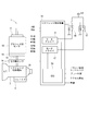
- the shift-by-wire system 1 is mounted on a vehicle.
- the vehicle is mounted with an engine, a radiator, a liquid temperature sensor, an oil temperature sensor, and an outside air temperature sensor.
- the radiator is supplied with a high-temperature coolant via a water jacket and an upper hose, which are coolant paths in the engine, and cools the coolant with the traveling wind of the vehicle.
- the radiator cools the coolant that has become high temperature, and returns to the engine after being cooled through the lower hose.
- As the cooling liquid an antifreeze liquid is mixed with water, and a long life coolant having an antirust and antiseptic effect is used as the antifreeze liquid.
- the motor 10 is a permanent magnet type DC brushless motor and includes an encoder 13 and a speed reducer 14.
- the encoder 13 can detect the rotational position of the rotor of the motor 10.
- the encoder 13 is, for example, a magnetic rotary encoder and includes a magnet that rotates integrally with the rotor and a Hall IC for magnetic detection.
- the encoder 13 outputs A-phase and B-phase pulse signals at predetermined angles in synchronization with the rotation of the rotor.
- a shift range switching device that switches a shift range by controlling a motor in response to a shift range switching request from a driver is known.
- an SR motor is used as a drive source for the shift range switching mechanism.
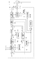
- the ECU 50 of the shift range control device 40 includes an angle calculation unit 51, a speed calculation unit 52, a feedback control unit 60, a stationary phase energization control unit 70, and a switching control unit 75.
- the ECU 50 is configured mainly with a microcomputer or the like.
- Each process in the ECU 50 may be a software process by a CPU executing a program stored in advance in a substantial memory device such as a ROM, or may be a hardware process by a dedicated electronic circuit.
- the angle calculation unit 51 calculates an actual count value Cen that is a count value of the encoder 13 based on the A-phase and B-phase pulses output from the encoder 13.
- the actual count value Cen is a value corresponding to the actual mechanical angle and electrical angle of the motor 10.
- the actual count value Cen is set to “actual angle”.
- the angle calculation unit 51 outputs the actual count value Cen to the speed calculation unit 52, the angle deviation calculation unit 61 of the feedback control unit 60, the PWM signal generation unit 69, and the stationary phase energization control unit 70.
- Current correcting unit 84 coolant temperature Hc, based on the oil temperature Ho and the outside air temperature Ha, calculates a temperature correction coefficient K T from the acquired motor current Im.
- the current correction unit 84 is in a state where the speed of the motor 10 to be described later is an acceleration state, and when the set temperature Hs, the coolant temperature Hc, and the outside air temperature Ha coincide with each other, or When Ha matches, the motor current Im is set as a normalized motor current Im_N.
- “match” is not a perfect match, but is also regarded as a “match” even when included in a common-sense error range.
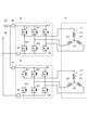
- the motor 10 is controlled by rectangular wave control by 120 ° energization.
- the first-phase high-potential side switching element and the second-phase low-potential side switching element are turned on.
- the energized phase is switched by switching the combination of the first phase and the second phase every 60 ° electrical angle. Thereby, a rotating magnetic field is generated in the winding sets 11 and 12, and the motor 10 rotates.
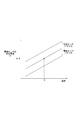
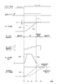
- the deceleration FF duty D_fd is calculated based on the relationship diagram, and is a duty that corrects deceleration of the motor speed Msp, and is a negative value. Further, the deceleration FF duty D_fd is a correction duty to achieve the target motor speed Msp *.
- the absolute value of the deceleration FF duty D_fd is set to increase as the motor speed Msp increases. Further, as the temperature correction coefficient KT increases, the motor temperature Hm decreases, the coil resistance Rc decreases, and the motor current Im flows easily. Therefore, the absolute value of the deceleration FF duty D_fd is set to decrease. ing. 9, 10, and 11 are cases where the motor 10 is rotating in the positive direction, and when the motor 10 rotates in the negative direction, the value is reversed.
- the FF correction value calculation unit 66 sets the acceleration FF duty D_fa as the FF duty D_ff when the speed state of the motor 10 is the acceleration state.
- the FF correction value calculation unit 66 sets the steady FF duty D_fi as the FF duty D_ff when the speed state of the motor 10 is a steady state.
- the FF correction value calculation unit 66 sets the deceleration FF duty D_fd as the FF duty D_ff when the speed state of the motor 10 is the deceleration state.
- the FF correction value calculation unit 66 outputs the calculated FF duty D_ff to the FF term correction unit 67.
- the FF term correction unit 67 is an integrator, corrects the FB duty D_fb with the FF duty D_ff, integrates it, and calculates the duty command value D.
- the voltage correction unit 68 corrects the duty command value D based on the battery voltage V.
- the corrected duty command value D is set as a corrected duty command value D_v.
- the voltage correction unit 68 outputs the corrected duty command value D_v to the PWM signal generation unit 69.
- the PWM signal generation unit 69 generates a command signal related to switching of the switching elements 411-416 and 421-426 based on the corrected duty command value D_v and the actual count value Cen.
- the PWM signal generation unit 69 acquires the motor current Im from the motor drivers 41 and 42, and adjusts the generated command signal so that the motor current Im does not exceed the current limit value Im_max. Further, the PWM signal generation unit 69 outputs a command signal to the switching control unit 75.
- the stationary phase energization control unit 70 selects the stationary phase and the energization direction based on the actual count value Cen so that the motor 10 stops at the electrical angle closest to the current rotor position. Further, the stationary phase energization control is performed when the angle deviation e becomes equal to or smaller than the angle determination threshold e_th. Therefore, when the fixed phase energization control is performed, it can be considered that the actual count value Cen and the target count value Cen * coincide. Therefore, the motor 10 can be stopped at a location that matches the target count value Cen * by stopping the motor 10 at the electrical angle that can be stopped closest to the current rotor position.
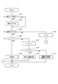
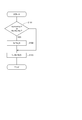
- step 169 the current correcting section 84 calculates a temperature correction coefficient K T from motor current Im. For the calculation of the temperature correction coefficient K T in step 169 will be described with reference to subflow of FIG.
- step 174 the controller 65 calculates the FB duty D_fb, outputs the calculated FB duty D_fb to the FF term correction unit 67, and the process proceeds to step 175.
- step 175 the FF correction value calculation unit 66 calculates the FF duty D_ff based on the speed state of the motor 10 and the temperature correction coefficient K T and outputs it to the FF term correction unit 67, and the process proceeds to step 176. .
- the detent plate is provided with four recesses.
- the number of recesses is not limited to four and may be any number.
- the shift range switching mechanism, the parking lock mechanism, and the like may be different from those in the above embodiment.
Landscapes
- Engineering & Computer Science (AREA)
- Power Engineering (AREA)
- General Engineering & Computer Science (AREA)
- Mechanical Engineering (AREA)
- Control Of Electric Motors In General (AREA)
- Gear-Shifting Mechanisms (AREA)
- Control Of Ac Motors In General (AREA)
- Control Of Motors That Do Not Use Commutators (AREA)
Priority Applications (3)
| Application Number | Priority Date | Filing Date | Title |
|---|---|---|---|
| US16/322,981 US10680542B2 (en) | 2016-09-09 | 2017-09-07 | Shift range control device |
| CN201780037822.9A CN109328278B (zh) | 2016-09-09 | 2017-09-07 | 档位范围控制装置 |
| DE112017004543.6T DE112017004543T5 (de) | 2016-09-09 | 2017-09-07 | Schaltbereichssteuerungsvorrichtung |
Applications Claiming Priority (2)
| Application Number | Priority Date | Filing Date | Title |
|---|---|---|---|
| JP2016176278A JP6565841B2 (ja) | 2016-09-09 | 2016-09-09 | シフトレンジ制御装置 |
| JP2016-176278 | 2016-09-09 |
Publications (1)
| Publication Number | Publication Date |
|---|---|
| WO2018047921A1 true WO2018047921A1 (ja) | 2018-03-15 |
Family
ID=61562528
Family Applications (1)
| Application Number | Title | Priority Date | Filing Date |
|---|---|---|---|
| PCT/JP2017/032361 Ceased WO2018047921A1 (ja) | 2016-09-09 | 2017-09-07 | シフトレンジ制御装置 |
Country Status (5)
| Country | Link |
|---|---|
| US (1) | US10680542B2 (enExample) |
| JP (1) | JP6565841B2 (enExample) |
| CN (1) | CN109328278B (enExample) |
| DE (1) | DE112017004543T5 (enExample) |
| WO (1) | WO2018047921A1 (enExample) |
Families Citing this family (11)
| Publication number | Priority date | Publication date | Assignee | Title |
|---|---|---|---|---|
| JP6708157B2 (ja) * | 2017-04-13 | 2020-06-10 | 株式会社デンソー | シフトレンジ制御装置 |
| JP6952498B2 (ja) * | 2017-05-31 | 2021-10-20 | 川崎重工業株式会社 | 位置制御装置 |
| JP6760232B2 (ja) * | 2017-09-05 | 2020-09-23 | 株式会社デンソー | シフトレンジ制御装置 |
| JP2019180133A (ja) * | 2018-03-30 | 2019-10-17 | 日本電産サーボ株式会社 | モータユニット |
| KR102100267B1 (ko) * | 2018-10-29 | 2020-04-13 | 현대오트론 주식회사 | 전동식 변속 레버 시스템의 위치 학습 시스템 |
| CN109838551B (zh) * | 2019-03-25 | 2021-04-16 | 法可赛(太仓)汽车配件有限公司 | 换挡执行机构的控制方法、装置及换挡控制系统 |
| KR102263101B1 (ko) * | 2019-12-03 | 2021-06-09 | 주식회사 현대케피코 | 전동식 변속 레버 시스템의 모터 위치 학습 장치 및 위치 학습 방법 |
| JP7287330B2 (ja) * | 2020-04-01 | 2023-06-06 | 株式会社デンソー | モータ制御装置 |
| KR20230032618A (ko) * | 2021-08-31 | 2023-03-07 | 에이치엘만도 주식회사 | 전자식 주차 브레이크 시스템 및 그 제어방법 |
| CN114454721B (zh) * | 2022-03-30 | 2024-07-19 | 广汽埃安新能源汽车有限公司 | 电动汽车降低电机轴承电腐蚀方法及电动汽车 |
| CN115217961B (zh) * | 2022-07-07 | 2023-06-27 | 东风汽车集团股份有限公司 | 换挡系统控制方法及相关设备 |
Citations (7)
| Publication number | Priority date | Publication date | Assignee | Title |
|---|---|---|---|---|
| JPH03107384A (ja) * | 1989-09-20 | 1991-05-07 | Mitsubishi Electric Corp | モータ駆動制御装置 |
| JP2001242904A (ja) * | 2000-03-02 | 2001-09-07 | Nippon Reliance Kk | 速度制御装置 |
| JP2004019804A (ja) * | 2002-06-17 | 2004-01-22 | Hitachi Unisia Automotive Ltd | 自動変速機の電動式レンジ切換装置 |
| JP2005106100A (ja) * | 2003-09-29 | 2005-04-21 | Calsonic Kansei Corp | 自動変速機のセレクトアシスト装置 |
| JP3886042B2 (ja) * | 2002-07-09 | 2007-02-28 | 株式会社デンソー | モータ制御装置 |
| JP2009095101A (ja) * | 2007-10-05 | 2009-04-30 | Denso Corp | モータ制御装置 |
| JP2012184079A (ja) * | 2011-03-04 | 2012-09-27 | Toshiba Elevator Co Ltd | エレベータの制御装置 |
Family Cites Families (9)
| Publication number | Priority date | Publication date | Assignee | Title |
|---|---|---|---|---|
| US7312595B2 (en) | 2002-07-09 | 2007-12-25 | Denso Corporation | Motor control apparatus |
| JP3849930B2 (ja) * | 2002-07-16 | 2006-11-22 | 株式会社デンソー | モータ制御装置 |
| JP4189953B2 (ja) | 2002-12-13 | 2008-12-03 | 株式会社デンソー | 位置切換制御装置 |
| JP4385768B2 (ja) | 2004-01-09 | 2009-12-16 | 株式会社デンソー | モータ制御装置 |
| JP5590076B2 (ja) * | 2012-07-04 | 2014-09-17 | 株式会社デンソー | 多相回転機の制御装置 |
| JP5762582B1 (ja) | 2014-02-04 | 2015-08-12 | 三菱電機株式会社 | シフトレンジ切り替え装置 |
| JP6361541B2 (ja) * | 2015-03-20 | 2018-07-25 | 株式会社デンソー | 回転電機の制御装置 |
| JP6185950B2 (ja) | 2015-03-20 | 2017-08-23 | 大建工業株式会社 | 透光パネルおよびそれを用いた建材 |
| JP6243385B2 (ja) * | 2015-10-19 | 2017-12-06 | ファナック株式会社 | モータ電流制御における補正値を学習する機械学習装置および方法ならびに該機械学習装置を備えた補正値計算装置およびモータ駆動装置 |
-
2016
- 2016-09-09 JP JP2016176278A patent/JP6565841B2/ja active Active
-
2017
- 2017-09-07 DE DE112017004543.6T patent/DE112017004543T5/de active Pending
- 2017-09-07 US US16/322,981 patent/US10680542B2/en not_active Expired - Fee Related
- 2017-09-07 WO PCT/JP2017/032361 patent/WO2018047921A1/ja not_active Ceased
- 2017-09-07 CN CN201780037822.9A patent/CN109328278B/zh active Active
Patent Citations (7)
| Publication number | Priority date | Publication date | Assignee | Title |
|---|---|---|---|---|
| JPH03107384A (ja) * | 1989-09-20 | 1991-05-07 | Mitsubishi Electric Corp | モータ駆動制御装置 |
| JP2001242904A (ja) * | 2000-03-02 | 2001-09-07 | Nippon Reliance Kk | 速度制御装置 |
| JP2004019804A (ja) * | 2002-06-17 | 2004-01-22 | Hitachi Unisia Automotive Ltd | 自動変速機の電動式レンジ切換装置 |
| JP3886042B2 (ja) * | 2002-07-09 | 2007-02-28 | 株式会社デンソー | モータ制御装置 |
| JP2005106100A (ja) * | 2003-09-29 | 2005-04-21 | Calsonic Kansei Corp | 自動変速機のセレクトアシスト装置 |
| JP2009095101A (ja) * | 2007-10-05 | 2009-04-30 | Denso Corp | モータ制御装置 |
| JP2012184079A (ja) * | 2011-03-04 | 2012-09-27 | Toshiba Elevator Co Ltd | エレベータの制御装置 |
Also Published As
| Publication number | Publication date |
|---|---|
| JP2018040463A (ja) | 2018-03-15 |
| CN109328278B (zh) | 2020-06-30 |
| US10680542B2 (en) | 2020-06-09 |
| CN109328278A (zh) | 2019-02-12 |
| US20190190411A1 (en) | 2019-06-20 |
| DE112017004543T5 (de) | 2019-05-23 |
| JP6565841B2 (ja) | 2019-08-28 |
Similar Documents
| Publication | Publication Date | Title |
|---|---|---|
| JP6565841B2 (ja) | シフトレンジ制御装置 | |
| US10948073B2 (en) | Shift range control device | |
| CN110325769B (zh) | 换挡挡位控制装置 | |
| US11226037B2 (en) | Shift range control device | |
| CN109075728B (zh) | 换挡挡位控制装置 | |
| US11002360B2 (en) | Shift range control apparatus | |
| JP6658416B2 (ja) | シフトレンジ制御装置 | |
| US10615724B2 (en) | Shift range control apparatus | |
| CN109073073B (zh) | 换挡挡位控制装置 | |
| JP6801551B2 (ja) | シフトレンジ制御装置 | |
| WO2018047916A1 (ja) | シフトレンジ制御装置 | |
| JP2019033620A (ja) | モータ制御装置 | |
| CN113748596B (zh) | 马达控制装置 |
Legal Events
| Date | Code | Title | Description |
|---|---|---|---|
| 121 | Ep: the epo has been informed by wipo that ep was designated in this application |
Ref document number: 17848859 Country of ref document: EP Kind code of ref document: A1 |
|
| 122 | Ep: pct application non-entry in european phase |
Ref document number: 17848859 Country of ref document: EP Kind code of ref document: A1 |