WO2018047782A1 - Système de surveillance de la pression des pneus - Google Patents
Système de surveillance de la pression des pneus Download PDFInfo
- Publication number
- WO2018047782A1 WO2018047782A1 PCT/JP2017/031840 JP2017031840W WO2018047782A1 WO 2018047782 A1 WO2018047782 A1 WO 2018047782A1 JP 2017031840 W JP2017031840 W JP 2017031840W WO 2018047782 A1 WO2018047782 A1 WO 2018047782A1
- Authority
- WO
- WIPO (PCT)
- Prior art keywords
- received
- tire pressure
- sensor
- vehicle
- request signal
- Prior art date
Links
Images


Classifications
-
- B—PERFORMING OPERATIONS; TRANSPORTING
- B60—VEHICLES IN GENERAL
- B60C—VEHICLE TYRES; TYRE INFLATION; TYRE CHANGING; CONNECTING VALVES TO INFLATABLE ELASTIC BODIES IN GENERAL; DEVICES OR ARRANGEMENTS RELATED TO TYRES
- B60C23/00—Devices for measuring, signalling, controlling, or distributing tyre pressure or temperature, specially adapted for mounting on vehicles; Arrangement of tyre inflating devices on vehicles, e.g. of pumps or of tanks; Tyre cooling arrangements
- B60C23/02—Signalling devices actuated by tyre pressure
- B60C23/04—Signalling devices actuated by tyre pressure mounted on the wheel or tyre
- B60C23/0408—Signalling devices actuated by tyre pressure mounted on the wheel or tyre transmitting the signals by non-mechanical means from the wheel or tyre to a vehicle body mounted receiver
- B60C23/0422—Signalling devices actuated by tyre pressure mounted on the wheel or tyre transmitting the signals by non-mechanical means from the wheel or tyre to a vehicle body mounted receiver characterised by the type of signal transmission means
- B60C23/0433—Radio signals
- B60C23/0435—Vehicle body mounted circuits, e.g. transceiver or antenna fixed to central console, door, roof, mirror or fender
- B60C23/0438—Vehicle body mounted circuits, e.g. transceiver or antenna fixed to central console, door, roof, mirror or fender comprising signal transmission means, e.g. for a bidirectional communication with a corresponding wheel mounted receiver
-
- B—PERFORMING OPERATIONS; TRANSPORTING
- B60—VEHICLES IN GENERAL
- B60C—VEHICLE TYRES; TYRE INFLATION; TYRE CHANGING; CONNECTING VALVES TO INFLATABLE ELASTIC BODIES IN GENERAL; DEVICES OR ARRANGEMENTS RELATED TO TYRES
- B60C23/00—Devices for measuring, signalling, controlling, or distributing tyre pressure or temperature, specially adapted for mounting on vehicles; Arrangement of tyre inflating devices on vehicles, e.g. of pumps or of tanks; Tyre cooling arrangements
- B60C23/02—Signalling devices actuated by tyre pressure
- B60C23/04—Signalling devices actuated by tyre pressure mounted on the wheel or tyre
- B60C23/0408—Signalling devices actuated by tyre pressure mounted on the wheel or tyre transmitting the signals by non-mechanical means from the wheel or tyre to a vehicle body mounted receiver
- B60C23/0422—Signalling devices actuated by tyre pressure mounted on the wheel or tyre transmitting the signals by non-mechanical means from the wheel or tyre to a vehicle body mounted receiver characterised by the type of signal transmission means
- B60C23/0433—Radio signals
- B60C23/0435—Vehicle body mounted circuits, e.g. transceiver or antenna fixed to central console, door, roof, mirror or fender
- B60C23/0438—Vehicle body mounted circuits, e.g. transceiver or antenna fixed to central console, door, roof, mirror or fender comprising signal transmission means, e.g. for a bidirectional communication with a corresponding wheel mounted receiver
- B60C23/0442—Vehicle body mounted circuits, e.g. transceiver or antenna fixed to central console, door, roof, mirror or fender comprising signal transmission means, e.g. for a bidirectional communication with a corresponding wheel mounted receiver the transmitted signal comprises further information, e.g. instruction codes, sensor characteristics or identification data
-
- B—PERFORMING OPERATIONS; TRANSPORTING
- B60—VEHICLES IN GENERAL
- B60C—VEHICLE TYRES; TYRE INFLATION; TYRE CHANGING; CONNECTING VALVES TO INFLATABLE ELASTIC BODIES IN GENERAL; DEVICES OR ARRANGEMENTS RELATED TO TYRES
- B60C23/00—Devices for measuring, signalling, controlling, or distributing tyre pressure or temperature, specially adapted for mounting on vehicles; Arrangement of tyre inflating devices on vehicles, e.g. of pumps or of tanks; Tyre cooling arrangements
- B60C23/02—Signalling devices actuated by tyre pressure
- B60C23/04—Signalling devices actuated by tyre pressure mounted on the wheel or tyre
- B60C23/0408—Signalling devices actuated by tyre pressure mounted on the wheel or tyre transmitting the signals by non-mechanical means from the wheel or tyre to a vehicle body mounted receiver
- B60C23/0422—Signalling devices actuated by tyre pressure mounted on the wheel or tyre transmitting the signals by non-mechanical means from the wheel or tyre to a vehicle body mounted receiver characterised by the type of signal transmission means
- B60C23/0433—Radio signals
- B60C23/0447—Wheel or tyre mounted circuits
- B60C23/0455—Transmission control of wireless signals
- B60C23/0462—Structure of transmission protocol
-
- G—PHYSICS
- G01—MEASURING; TESTING
- G01L—MEASURING FORCE, STRESS, TORQUE, WORK, MECHANICAL POWER, MECHANICAL EFFICIENCY, OR FLUID PRESSURE
- G01L17/00—Devices or apparatus for measuring tyre pressure or the pressure in other inflated bodies
-
- G—PHYSICS
- G07—CHECKING-DEVICES
- G07C—TIME OR ATTENDANCE REGISTERS; REGISTERING OR INDICATING THE WORKING OF MACHINES; GENERATING RANDOM NUMBERS; VOTING OR LOTTERY APPARATUS; ARRANGEMENTS, SYSTEMS OR APPARATUS FOR CHECKING NOT PROVIDED FOR ELSEWHERE
- G07C5/00—Registering or indicating the working of vehicles
- G07C5/08—Registering or indicating performance data other than driving, working, idle, or waiting time, with or without registering driving, working, idle or waiting time
- G07C5/0808—Diagnosing performance data
-
- B—PERFORMING OPERATIONS; TRANSPORTING
- B60—VEHICLES IN GENERAL
- B60C—VEHICLE TYRES; TYRE INFLATION; TYRE CHANGING; CONNECTING VALVES TO INFLATABLE ELASTIC BODIES IN GENERAL; DEVICES OR ARRANGEMENTS RELATED TO TYRES
- B60C23/00—Devices for measuring, signalling, controlling, or distributing tyre pressure or temperature, specially adapted for mounting on vehicles; Arrangement of tyre inflating devices on vehicles, e.g. of pumps or of tanks; Tyre cooling arrangements
- B60C23/20—Devices for measuring or signalling tyre temperature only
Definitions
- the present disclosure relates to a tire pressure monitoring system (hereinafter referred to as TPMS: Tire Pressure Monitoring System).
- TPMS Tire Pressure Monitoring System
- the tire pressure is detected only while the ignition switch (hereinafter referred to as IG) in the vehicle is on. For this reason, there is only air pressure information collected before parking immediately after the IG is turned on, and the tire pressure cannot be detected based on the air pressure information during the IG off. However, even when the vehicle is stopped, the tire pressure may be reduced naturally or the tire pressure may be reduced due to puncture. Therefore, it is desired that the tire air pressure is detected as soon as possible after the IG is turned on.
- IG ignition switch
- TPMS in which an antenna capable of transmitting LF (abbreviation of Low Frequency) is arranged near each tire.
- LF abbreviation of Low Frequency
- a sensor transmitter provided in each tire, thereby transmitting tire pressure data from the sensor transmitter.
- an antenna capable of transmitting LF radio waves is installed near each wheel, and an LF transmission driver for transmitting LF radio waves is required, resulting in an increase in the number of components and a high-cost system.
- RF radio waves are used when sending detection results such as tire pressure from each sensor transmitter. Therefore, each sensor transmitter is already provided with a transmitter and an antenna that perform RF transmission.
- the transmitter that performs RF transmission, the receiver that performs RF reception, and the antenna can be shared. For this reason, an increase in the number of parts can be suppressed by sharing a transmitter for RF transmission and a receiver for RF reception, or by sharing antennas for transmission and reception, and a low-cost system can be realized. become.
- the RF reception can always be performed, the current consumption increases because the RF radio wave has a high frequency. Since the sensor transmitter is installed in the tire and isolated from the vehicle body, it is essential to reduce current consumption from the viewpoint of battery life. Simply use RF radio waves and turn on the RF radio waves to the sensor transmitter after IG is turned on. If this is done, the battery life will be reduced.
- An object is to provide a TPMS that can be detected.
- the TPMS in one aspect of the present disclosure is provided in each of a plurality of wheels, a sensing unit that detects tire pressure of each of the plurality of wheels, a first control unit that creates a frame that stores data related to the tire pressure, A sensor transceiver having a first transmitter for transmitting a frame created by the first controller as an RF radio wave, and a first receiver for receiving the RF radio wave, and provided on the vehicle body side and transmitted from the sensor transceiver. A second receiving unit that receives the received frame, a second control unit that detects the tire pressure of each of the plurality of wheels based on the received frame, and a second transmitting unit that transmits an RF radio wave to be received by the first receiving unit. And a vehicle body side system.
- the first receiving unit continuously transmits the RF radio wave as an RF radio wave to the sensor transceiver.
- a request signal for requesting transmission of a frame is output after outputting a burst signal for enabling reception of a frame.
- the second control unit sets the first receiving unit in a standby state in which the RF radio wave can be intermittently received, and sets the first receiving unit in a standby state in which the first receiving unit can intermittently receive the RF radio wave. If a burst signal is received while the signal is being received, the first reception unit is made to be able to continuously receive RF radio waves, and the request signal is received. When the request signal is received, a frame is transmitted in response.
- the sensor transceiver is in a state in which RF radio waves can be received intermittently.
- the sensor transceiver is configured to be able to continuously receive RF radio waves accordingly.
- the tire pressure can be detected earlier by transmitting data related to the tire pressure to the vehicle body system based on the request signal from the vehicle body system. .
- the sensor transceiver is set in a standby state in which the RF radio wave can be received, but is only intermittently performed. Therefore, it is possible to reduce current consumption. . Furthermore, it is not necessary to provide an antenna or the like for transmitting LF radio waves near each wheel.
- a TPMS capable of detecting tire air pressure earlier can be achieved while suppressing an increase in current consumption.
- FIG. 1 is a block diagram showing the overall configuration of the TPMS according to the present embodiment.
- the upward direction in the drawing corresponds to the front of the vehicle 1
- the downward direction in the drawing corresponds to the rear of the vehicle 1.
- the TPMS is attached to the vehicle 1 and includes a sensor transceiver 2 and a vehicle body side system 3.
- one sensor transceiver 2 is attached to each wheel 4a to 4d in the vehicle 1.
- the sensor transceiver 2 basically detects the air pressure of the tires attached to the wheels 4a to 4d and the temperature in the tires while the vehicle 1 is traveling, and frame the detection signal data indicating the detection results. It functions as a transmitter that stores and transmits the data inside.
- the sensor transceiver 2 also functions as a receiver that receives RF radio waves transmitted from the vehicle body side system 3 as will be described later. When the sensor transceiver 2 receives the RF radio wave, the sensor transceiver 2 detects the tire pressure and the temperature in the tire, and stores the data indicating the detection result in the frame for transmission.
- the vehicle body side system 3 is provided on the vehicle body 5 side of the vehicle 1 and receives a frame transmitted from the sensor transceiver 2 and performs various processes and calculations based on the data stored therein. I am looking for tire pressure.
- the vehicle body side system 3 transmits an RF radio wave to the sensor transceiver 2 based on the IG and quickly detects the tire air pressure and the temperature in the tire from the sensor transceiver 2. It is trying to convey.
- the vehicle body side system 3 alerts the user that the tire air pressure is abnormal, thereby alerting the user.
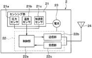
- the sensor transceiver 2 is configured to include a sensing unit 21, a microcomputer 22, a battery 23, and an antenna 24.
- the sensing unit 21 includes a pressure sensor 21a, a temperature sensor 21b, and an acceleration sensor 21c.
- the pressure sensor 21a and the temperature sensor 21b output a detection signal (hereinafter referred to as a detection signal related to the tire pressure) indicating the tire air pressure and the temperature in the tire, and each detection signal is output to the microcomputer 22.
- a detection signal related to the tire pressure hereinafter referred to as a detection signal related to the tire pressure
- the acceleration sensor 21 c outputs an acceleration detection signal including an acceleration component in the radial direction of each of the wheels 4 a to 4 d, that is, an acceleration component in the centrifugal direction, and inputs it to the microcomputer 22. ing.
- the sensing unit 21 detects acceleration for each predetermined detection cycle based on a command from the microcomputer 22. In addition, the sensing unit 21 detects the tire air pressure and the temperature in the tire for each predetermined periodic transmission period during a period in which the vehicle 1 continues to travel after receiving a command from the microcomputer 22.
- the microcomputer 22 is a well-known computer having a CPU, ROM, RAM, I / O, and the like, and executes predetermined processing according to a program stored in the ROM.
- the microcomputer 22 includes a control unit 22a, a transmission unit 22b, a reception unit 22c, and the like, and performs various processes related to tire pressure monitoring according to a program stored in a built-in memory of the control unit 22a. Yes.
- the control unit 22a corresponds to the first control unit.
- the RF radio wave transmitted from the vehicle body side system 3 when the IG is turned on is detected.
- the receiving unit 22c is set in a standby state in which the RF radio wave can be received so that the transceiver 2 can receive the signal.
- the control unit 22a places the receiving unit 22c in a standby state in which the RF radio wave can be received, for example, at predetermined intervals so that the RF radio wave can be received intermittently.
- the vehicle body side system 3 first sends a burst signal for making the receiving unit 22c of each sensor transceiver 2 continuously receive RF radio waves as RF radio waves. Subsequently, the vehicle body side system 3 requests transmission of data indicating the detection result of the tire pressure and the temperature in the tire (hereinafter, data related to the tire pressure) to each sensor transceiver 2 as an RF radio wave. A signal is sent.
- the control unit 22a maintains the reception unit 22c in a standby state in which the RF radio wave can be received, and continues that state until the request signal arrives. More specifically, the request signal stores unique identification information (hereinafter referred to as ID information) of each sensor transceiver 2 and includes a request signal including the ID information of each sensor transceiver 2 in order at different timings. Output from the vehicle body side system 3. For this reason, the control unit 22a of each sensor transceiver 2 keeps the receiving unit 22c in a standby state in which the RF radio wave can be continuously received until the request signal including its own ID information is received. When it arrives, the standby state is canceled.
- ID information unique identification information
- control unit 22a times out and returns the reception unit 22c to the standby state in which the RF signal can be received intermittently again.
- control part 22a will perform the process for transmitting the data regarding tire pressure toward the vehicle body side system 3 as a response, if the request signal containing own ID information is received. Specifically, the control unit 22a receives a detection signal related to the tire air pressure from the sensing unit 21, processes the signal and processes it as necessary, and processes the detection result as data related to the tire air pressure. Together with the ID information. Then, the frame is sent to the transmission unit 22b.
- the control unit 22a performs different operations depending on whether or not the vehicle 1 is running. That is, since it is desired to detect the tire air pressure during traveling, the control unit 22a causes the sensing unit 21 to detect the tire air pressure and the temperature in the tire every predetermined periodic transmission cycle, and based on the tire air pressure data based on the tire air pressure data. Processing to create and send to the transmission unit 22b is performed. Conversely, the need for tire pressure detection is not high while the vehicle is stopped. Further, the sensor transceiver 2 cannot grasp whether the IG is on or off.
- the control unit 22a basically enters a sleep state, wakes up at predetermined intervals, and puts the reception unit 22c into a standby state in which RF radio waves can be received. As with IG off, RF radio waves can be received intermittently. Whether or not the vehicle 1 is traveling can be detected based on the detection signal of the acceleration sensor 21c.
- the transmission unit 22b corresponds to a first transmission unit, and functions as an output unit that transmits the frame transmitted from the control unit 22a to the vehicle body side system 3 through the antenna 24.
- the transmission unit 22b constitutes an RF transmission unit that performs frame transmission using RF radio waves.
- the receiving unit 22c corresponds to a first receiving unit, and functions as an input unit that receives an RF radio wave transmitted from the vehicle body side system 3 through the antenna 24.
- the receiving unit 22c receives the signal and transmits it to the control unit 22a.
- the receiving unit 22c is normally in a state where it cannot receive RF radio waves, but enters a standby state in which RF radio waves can be received according to a request from the control unit 22a.
- the transmission part 22b and the receiving part 22c are described as a separate functional block here, it becomes possible to make these common. That is, the function of transmitting and receiving RF radio waves can be realized by the same structure. For this reason, the transmission part 22b and the reception part 22c can be comprised as one transmission / reception part, and a low-cost system is realizable. Of course, even if the transmitting unit 22b and the receiving unit 22c are configured separately, the antenna 24 can be shared, so that even in that case, a low-cost system can be realized.
- the battery 23 supplies power to the control unit 22a and the like, and receives power supply from the battery 23, collects data related to tire pressure in the sensing unit 21, detects acceleration, and controls the control unit 22a. Various calculations are executed. Since the sensor transceiver 2 is provided in the tire, replacement of the battery 23 is not easy, and it is necessary to suppress current consumption. For this reason, it is effective to be able to suppress current consumption by shortening the period during which the receiving unit 22c is operated as described above.
- the antenna 24 receives RF radio waves transmitted from the vehicle body side system 3 and transmits RF radio waves to the vehicle body side system 3. Since RF radio waves are transmitted and received, the antenna 24 may be configured separately for LF radio wave transmission and RF radio wave transmission. However, by using a single antenna, the cost can be reduced by reducing the number of components. be able to.
- the sensor transceiver 2 configured in this manner is attached to an air injection valve in each of the wheels 4a to 4d, for example, and is arranged so that the sensing unit 21 is exposed inside the tire.
- the tire air pressure of the corresponding wheel is detected, and a frame storing data related to the tire air pressure is transmitted through the antenna 24 provided in each sensor transceiver 2.
- the tire air pressure of the corresponding wheel is detected, and data relating to the tire air pressure is stored every predetermined periodic transmission cycle, for example, every minute through the antenna 24 provided in each sensor transceiver 2. Send the frame.
- the data relating to the tire pressure is sent together with the ID information of each sensor transceiver 2 provided in the vehicle.
- the position of each wheel can be specified by a known wheel position detection device that detects which position of the vehicle the wheel is attached to. For this reason, it is possible to determine which wheel data is transmitted by transmitting data related to the tire pressure together with the ID information to the transceiver 30.
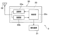
- the vehicle body side system 3 is configured to include a transceiver 30 and a notification device 31.
- Each part which comprises the vehicle body side system 3 is connected through in-vehicle LAN (abbreviation of Local * AreaNetwork) by CAN (abbreviation of Controller
- in-vehicle LAN abbreviation of Local * AreaNetwork
- CAN abbreviation of Controller
- the transceiver 30 is configured to include an antenna 32 and a microcomputer 33.
- the antenna 32 outputs burst signals and request signals as RF radio waves to the sensor transceivers 2 and receives frames transmitted as RF radio waves from the sensor transceivers 2.
- the antenna 32 is fixed to the vehicle body 5. Yes. Since both transmission and reception are performed using RF radio waves, the antenna 32 is shared for RF radio wave transmission and RF radio wave reception, so that a low-cost system can be realized by reducing the number of components. Yes.
- the microcomputer 33 is a well-known computer having a CPU, ROM, RAM, I / O, and the like, and executes predetermined processing according to a program stored in the ROM.
- the microcomputer 33 includes a transmission unit 33a, a reception unit 33b, and a control unit 33c, and performs various processes related to tire pressure monitoring according to a program stored in a built-in memory of the control unit 33c.
- the transmission unit 33a corresponds to a second transmission unit, and functions as an output unit that transmits a burst signal and a request signal as an RF radio wave through the antenna 32.
- the transmission unit 33a transmits a burst signal or a request signal as an RF radio wave through the antenna 32 in accordance with an instruction from the control unit 33c.
- an instruction to output a burst signal is issued from the control unit 33c to the transmission unit 33a, and accordingly, the burst signal is transmitted from the transmission unit 33a as an RF radio wave.
- the request signal is transmitted as an RF radio wave from the transmission unit 33a accordingly.
- the request signal also includes ID information of each sensor transceiver 2, and the request signal including the ID information of each sensor transceiver 2 in order is transmitted from the control unit 33c at different timings, and the transmission unit 33a. Transmits it in turn to each sensor transceiver 2.
- the receiving unit 33b corresponds to a second receiving unit, and functions as an input unit that inputs a frame from each sensor transceiver 2 received by the antenna 32 and sends the frame to the control unit 33c.
- the control unit 33c corresponds to a second control unit, and obtains tire air pressure by performing various signal processing and calculations based on data related to tire air pressure stored in the received frame, and tire air pressure is calculated based on the tire air pressure. Determining a decrease in Specifically, the control unit 33c compares the tire air pressure with an alarm threshold value, and determines that the tire air pressure is decreased when the tire air pressure becomes equal to or lower than the alarm threshold value. And if the fall of tire air pressure is detected, control part 33c will output the signal to that effect to informing device 31. As a result, the notification device 31 is informed that the tire pressure of any of the wheels 4a to 4d has decreased.
- the control unit 33c instructs the transmission unit 33a to output a burst signal.
- a burst signal is output as an RF radio wave from the transmission unit 33a through the antenna 32, and the reception unit 22c of each sensor transceiver 2 is ready to receive the RF radio wave.
- the control unit 33c outputs a request signal instructing each sensor transceiver 2 to transmit data related to the tire pressure in order. That is, the request signal is transmitted a number of times corresponding to the number of wheels 4a to 4d, and the ID information of each sensor transceiver 2 is included in each request signal in order.
- data relating to tire pressure is sent from each sensor transceiver 2 to the transceiver 30 to determine a decrease in tire air pressure of each wheel 4a-4d. ing.
- the notification device 31 is disposed at a place where a driver who is a user can visually recognize the vehicle while driving, for example, in an instrument panel in the vehicle 1.
- the notification device 31 is composed of, for example, a meter display, a warning lamp, and the like.
- a notification signal instructing notification of a decrease in tire air pressure is sent from the control unit 33c in the transceiver 30, a notification to that effect is displayed. To inform the driver of the decrease in tire pressure.
- the TPMS in this embodiment is configured. Subsequently, an operation example of the TPMS configured as described above will be described. However, in the operation of the TPMS, various processes performed by the sensor transceiver 2 for periodic transmission and determination of a decrease in tire air pressure performed when the transceiver 30 receives a frame that has been transmitted periodically are conventional and It is the same. For this reason, here, the processing when the IG is switched from off to on will be mainly described with reference to FIGS. 4A, 4B, 5 and 6. FIG.
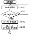
- control unit 33c executes the start-up detection process shown in FIGS. 4A and 4B for each predetermined control period.
- ID information of each sensor transceiver 2 attached to each of the wheels 4a to 4d will be simply described as ID1 to ID4.
- step S100 an IG state recognition process is performed. Thereby, it is recognized whether IG is on or off. Subsequently, the process proceeds to step S105, where it is determined whether or not the IG has been switched from OFF to ON. When the IG has been switched from OFF to ON, the process proceeds to step S110, and the IG continues to be on after the IG is switched off or off to on. When in the middle state, the process returns to step S100.
- step S110 the transmission unit 33a is instructed to transmit a burst signal. Thereby, a burst signal is transmitted from the transmission unit 33a through the antenna 32.
- each sensor transceiver 2 is ready to receive RF radio waves.
- step S115 the transmission unit 33a is instructed to transmit a request signal to the sensor transceiver 2 of ID1. Accordingly, a request signal including ID1 as ID information is transmitted from the transmission unit 33a through the antenna 32.
- the sensor transceiver 2 of ID1 transmits a frame in which data relating to tire pressure is stored together with its own ID information in response.
- step S120 it is determined whether or not there is a normal response from the sensor transceiver 2 of ID1.
- a response from the sensor transceiver 2 of ID1 when there is a response from the sensor transceiver 2 of ID1, and a frame including ID information of ID1 is received, an affirmative determination is made in step S120. If the frame is not received or if there is any abnormal response from the sensor transceiver 2 of ID1, a negative determination is made.
- the abnormal response is a response that is performed when the sensor transceiver 2 cannot normally transmit data related to tire pressure due to, for example, a failure of the sensing unit 21. In that case, a frame indicating an abnormal response is transmitted from the sensor transceiver 2 so that the controller 33c can confirm that it is an abnormal response.
- step S120 If an affirmative determination is made in step S120, the process proceeds to step S125 and step S130, and this time, the same operation as that for the sensor transceiver 2 of ID1 is performed on the sensor transceiver 2 of ID2. That is, by instructing the transmitter 33a to transmit a request signal to the sensor transceiver 2 of ID2, the transmitter 33a transmits a request signal including ID2 through the antenna 32, and then from the sensor transceiver 2 of ID2 It is determined whether there is a normal response. Also here, if there is a normal response from the sensor transceiver 2 of ID2, an affirmative determination is made, and if not, a negative determination is made.
- step S130 If an affirmative determination is made in step S130, the process proceeds to step S135 and step S140, and this time, the same operation as that for the sensor transceiver 2 of ID1 is performed on the sensor transceiver 2 of ID3.
- step S140 an affirmative determination is made if there is a normal response from the sensor transceiver 2 of ID3, and a negative determination is made if there is no response.
- step S140 when an affirmative determination is made in step S140, the process proceeds to step S145 and step S150, and finally, the same processing as that of the sensor transceiver 2 of ID1 is performed on the sensor transceiver 2 of ID4.
- step S150 an affirmative determination is made if there is a normal response from the sensor transceiver 2 of ID4, and a negative determination is made if there is no response. If an affirmative determination is made here as well, the process proceeds to step S155, and the recognition of the tire pressure is completed for all the sensor transceivers 2 of ID1 to ID4, and the process is terminated.
- steps S120, S130, S140, and S150 the process proceeds to steps S160, S170, S180, and S190, respectively, to determine whether or not there is an abnormal response. If there is an abnormal response, the tire air pressure cannot be detected, so the process is terminated. In this case, for example, a signal indicating that the tire pressure cannot be detected may be sent to the notification device 31 to notify the user that the tire pressure cannot be detected through the notification device 31.
- steps S165, S175, S185, and S195 respectively, and it is determined whether or not a TIME OUT has elapsed after a predetermined time without any response. If the determination is affirmative, the process is terminated. If the determination is negative, the process returns to steps S120, S130, S140, and S150, and the process is repeated.
- the above processing is performed. Then, when the recognition of the tire pressure of each wheel 4a to 4d is completed, it is determined whether or not the tire pressure is reduced. Instructs the tire pressure drop notification. Thereby, it is possible to notify the user of a decrease in tire air pressure through the notification device 31.
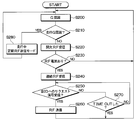
- the control unit 22a executes the sensor response process shown in FIG. 5 for each predetermined control period.
- step S200 acceleration is recognized from the detection signal of the acceleration sensor 21c as acceleration recognition processing. And it progresses to step S210 and it is determined whether the driving
- the detection signal of the acceleration sensor 21c includes the acceleration component in the centrifugal direction based on the rotation of the wheels 4a to 4d to which the sensor transceiver 2 is attached in addition to the gravitational acceleration. If the acceleration component in the centrifugal direction is recognized as the traveling acceleration G as the acceleration component in the centrifugal direction, the traveling acceleration G is recognized. If a negative determination is made in step S210, the process proceeds to step S220, and intermittent RF reception processing is performed. That is, the control unit 22a places the receiving unit 22c in a standby state in which RF radio waves can be received intermittently.
- step S230 it is determined whether or not reception of an RF radio wave, specifically, a burst signal has been received, and the processes of steps S200 to S220 are repeated until reception is received. Proceed to step S240.
- step S240 continuous RF reception processing is performed. That is, the control unit 22a places the receiving unit 22c in a standby state in which the RF radio wave can be continuously received. As a result, the receiving unit 22c enters a standby state in which the RF radio wave can be continuously received until the request signal arrives. Thereafter, in step S250, it is determined whether or not a request signal including its own ID information has been received. If it has been received, the process proceeds to step S260. As a response to the request signal, data relating to tire pressure is received as its ID information. The frame stored together with this is transmitted as an RF radio wave.
- step S270 it is determined whether a TIME OUT has elapsed after a predetermined time has elapsed without receiving the request signal. Then, the processes in steps S240 and S250 are repeated until TIME OUT, and when TIME OUT, the process is terminated and the process is repeated from step S200.
- step S210 determines whether an affirmative determination is made in step S210 or not. If an affirmative determination is made in step S210, the process proceeds to step S280, and the periodic RF transmission mode during traveling is set.
- periodic transmission is performed in which a frame in which data related to tire air pressure is stored together with its own ID information is transmitted every predetermined periodic transmission cycle.
- FIG. 6 is a time chart when the above operation is performed.
- each sensor transceiver 2 when the IG before time ta is off, each sensor transceiver 2 is in a standby state in which RF radio waves can be received intermittently.
- a standby state is established in which RF radio waves can be received every predetermined period T that is shorter than the transmission time TB of the burst signal, and RF radio waves can be received during the period t.
- the current consumption during this period t is, for example, 12 mA.
- a burst signal is transmitted as an RF radio wave from the transceiver 30 of the vehicle body side system 3.
- each sensor transceiver 2 is in a standby state in which it can receive RF radio waves with its own ID information, that is, a period until a request signal arrives. become.
- the vehicle body side system 3 After that, at time tb, the vehicle body side system 3 outputs a request signal of ID1, and then enters a standby state in which the RF radio wave can be received so that the RF radio wave as a response from the sensor transceiver 2 can be received.
- the sensor transmitter / receiver 2 of ID1 cancels the state in which the RF radio wave can be received in response to the request signal, and transmits a frame including data related to tire pressure as a response to the request signal at time tc.
- an ID2 request signal is output from the vehicle body side system 3 at the time point td
- the same operation as described above is performed, and a frame including data related to tire air pressure is transmitted from the ID2 sensor transmitter at the time point te.
- an ID3 request signal is output from the vehicle body side system 3 at time tf
- a frame including data related to tire pressure is transmitted from the ID3 sensor transmitter at time tg.
- the request signal of ID4 is output from the vehicle body side system 3 at the time point th, a frame including data relating to tire air pressure is transmitted from the sensor transmitter of ID4 at the time point ti.
- each sensor transceiver 2 in response to the request signal from the vehicle body side system 3, the frame including the data related to the tire pressure is sent from each of the sensor transceivers ID 1 to ID 4 and is received by the vehicle body side system 3.
- the tire pressure of each wheel 4a to 4d is detected. Accordingly, it is possible to detect the tire air pressure of each of the wheels 4a to 4d immediately after the IG is switched from on to off.
- each sensor transceiver 2 since each sensor transceiver 2 is in a standby state in which RF radio waves can be received intermittently rather than continuously, it is possible to reduce current consumption. Since each sensor transceiver 2 has a period T at which RF radio waves can be received intermittently shorter than the burst signal transmission time, each sensor transceiver 2 can reliably receive the burst signal. It becomes.
- each sensor transceiver 2 enters a standby state in which the RF radio wave can be intermittently received again from the time point tj after a predetermined time has elapsed. Then, when the traveling acceleration G is recognized, the periodic RF transmission mode in which data relating to the tire pressure is transmitted every periodic transmission cycle is set.
- the sensor transceiver 2 is intermittently capable of receiving RF radio waves. Further, when a burst signal is sent as RF radio waves from the vehicle body side system 3, the sensor transceiver 2 is continuously ready to receive RF radio waves. When the sensor transceiver 2 can receive the RF radio wave, the tire pressure can be detected earlier by transmitting the data related to the tire pressure to the vehicle body system 3 based on the request signal from the vehicle body system 3. It becomes possible.
- the sensor transmitter / receiver 2 Before receiving the burst signal, the sensor transmitter / receiver 2 is in a standby state in which the RF radio wave can be received and is only intermittently performed. Therefore, current consumption can be reduced. Become. Furthermore, it is not necessary to provide an antenna or the like for transmitting LF radio waves near each wheel.
- a TPMS capable of detecting tire air pressure earlier can be achieved while suppressing an increase in current consumption.
- the TPMS described here is designed to promptly detect the tire air pressure when it is detected that the vehicle 1 may start.
- the vehicle 1 for example, the case where the IG is switched from OFF to ON is taken as an example, but at least 1 including other conditions described below is included.
- a smart key system registered trademark
- a smart key registered trademark
- the electronic key is authenticated as being within a predetermined authentication range from the door, it may be detected that the vehicle may start.
- the transmitter / receiver 30 of the vehicle body side system 3 is provided with a transmitter 33a and a receiver 33b capable of transmitting and receiving RF radio waves.
- a configuration capable of performing transmission and reception of RF radio waves, that is, bidirectional communication bidirectional communication with the sensor transceiver 2 is performed there.
- parts can be shared and the number of parts can be further reduced.
- the vehicle 1 since the vehicle 1 includes a system that performs bidirectional communication with the electronic key, it is also possible to perform bidirectional communication with the sensor transceiver 2 using the system. .
- the IG is described as an example of the start switch that is operated when the vehicle 1 is started, but this is an example in which the present disclosure is applied to an internal combustion engine vehicle.
- the start switch is not always IG.
- the start switch may be configured by a push switch or the like, and the present disclosure can be applied to such a case.
Abstract
La présente invention concerne un émetteur-récepteur de capteur (2) qui est amené dans un état dans lequel il est possible de recevoir des signaux RF intermittents. De plus, en réponse à un signal de salve, transmis sous la forme d'un signal RF, provenant d'un système côté véhicule (3), l'émetteur-récepteur de capteur (2) est amené dans un état dans lequel la réception continue de signaux RF est activée. Après étant activé afin de recevoir les signaux RF, l'émetteur-récepteur de capteur (2) transmet des données concernant la pression de gonflage au système côté véhicule (3), en fonction d'un signal de demande provenant du système côté véhicule (3), ce qui permet une détection précoce de la pression de gonflage.
Priority Applications (1)
| Application Number | Priority Date | Filing Date | Title |
|---|---|---|---|
| US16/326,286 US11298990B2 (en) | 2016-09-06 | 2017-09-04 | Tire pressure monitoring system |
Applications Claiming Priority (2)
| Application Number | Priority Date | Filing Date | Title |
|---|---|---|---|
| JP2016-173734 | 2016-09-06 | ||
| JP2016173734A JP6547714B2 (ja) | 2016-09-06 | 2016-09-06 | タイヤ空気圧監視システム |
Publications (1)
| Publication Number | Publication Date |
|---|---|
| WO2018047782A1 true WO2018047782A1 (fr) | 2018-03-15 |
Family
ID=61562094
Family Applications (1)
| Application Number | Title | Priority Date | Filing Date |
|---|---|---|---|
| PCT/JP2017/031840 WO2018047782A1 (fr) | 2016-09-06 | 2017-09-04 | Système de surveillance de la pression des pneus |
Country Status (3)
| Country | Link |
|---|---|
| US (1) | US11298990B2 (fr) |
| JP (1) | JP6547714B2 (fr) |
| WO (1) | WO2018047782A1 (fr) |
Families Citing this family (7)
| Publication number | Priority date | Publication date | Assignee | Title |
|---|---|---|---|---|
| CN107808430B (zh) * | 2017-10-31 | 2020-01-31 | 深圳市道通合创软件开发有限公司 | 计算机可读存储介质、故障检测方法及装置 |
| JP6791173B2 (ja) * | 2018-01-09 | 2020-11-25 | 株式会社Soken | 携帯機位置検出装置 |
| JP7167835B2 (ja) * | 2019-04-24 | 2022-11-09 | 株式会社デンソー | タイヤ空気圧監視システム |
| US20210081863A1 (en) * | 2019-07-25 | 2021-03-18 | Airwire Technologies | Vehicle intelligent assistant |
| JP7472767B2 (ja) * | 2020-12-03 | 2024-04-23 | 株式会社デンソー | ネットワークシステム |
| DE102021202101A1 (de) * | 2021-03-04 | 2022-09-08 | Robert Bosch Gesellschaft mit beschränkter Haftung | Verfahren zum Betreiben einer Überwachungsvorrichtung für zumindest einen Fahrzeugparameter |
| KR102528661B1 (ko) * | 2021-11-26 | 2023-05-04 | 주식회사 코아칩스 | 경전철 타이어에서 타이어 상태 측정을 위한 장치 |
Citations (3)
| Publication number | Priority date | Publication date | Assignee | Title |
|---|---|---|---|---|
| JP2001250186A (ja) * | 2000-03-06 | 2001-09-14 | Denso Corp | 車両用タイヤ空気圧監視システム |
| JP2003272060A (ja) * | 2002-03-13 | 2003-09-26 | Pacific Ind Co Ltd | タイヤ状態監視装置 |
| JP2012179973A (ja) * | 2011-02-28 | 2012-09-20 | Tokai Rika Co Ltd | 車両の無線通信システム及びタイヤ空気圧監視システム |
Family Cites Families (3)
| Publication number | Priority date | Publication date | Assignee | Title |
|---|---|---|---|---|
| US20070194896A1 (en) * | 2006-02-17 | 2007-08-23 | Wabash National, L.P. | Wireless tire status monitor and monitoring system |
| JP2013006588A (ja) | 2011-05-20 | 2013-01-10 | Denso Corp | タイヤ空気圧検出装置 |
| KR101509002B1 (ko) * | 2013-11-28 | 2015-04-14 | 현대모비스 주식회사 | 타이어 압력 모니터링 장치 및 그 방법 |
-
2016
- 2016-09-06 JP JP2016173734A patent/JP6547714B2/ja active Active
-
2017
- 2017-09-04 US US16/326,286 patent/US11298990B2/en active Active
- 2017-09-04 WO PCT/JP2017/031840 patent/WO2018047782A1/fr active Application Filing
Patent Citations (3)
| Publication number | Priority date | Publication date | Assignee | Title |
|---|---|---|---|---|
| JP2001250186A (ja) * | 2000-03-06 | 2001-09-14 | Denso Corp | 車両用タイヤ空気圧監視システム |
| JP2003272060A (ja) * | 2002-03-13 | 2003-09-26 | Pacific Ind Co Ltd | タイヤ状態監視装置 |
| JP2012179973A (ja) * | 2011-02-28 | 2012-09-20 | Tokai Rika Co Ltd | 車両の無線通信システム及びタイヤ空気圧監視システム |
Also Published As
| Publication number | Publication date |
|---|---|
| JP6547714B2 (ja) | 2019-07-24 |
| US20190184774A1 (en) | 2019-06-20 |
| US11298990B2 (en) | 2022-04-12 |
| JP2018039326A (ja) | 2018-03-15 |
Similar Documents
| Publication | Publication Date | Title |
|---|---|---|
| WO2018047782A1 (fr) | Système de surveillance de la pression des pneus | |
| JP3636184B2 (ja) | タイヤ空気圧センサのid登録方法及びid登録システムと、タイヤ空気圧監視システム、タイヤ空気圧センサ及びスマート制御システム | |
| WO2015015692A1 (fr) | Dispositif de détection de pression d'air d'un pneumatique | |
| JP4810894B2 (ja) | タイヤ空気圧の情報を受信するための車体側通信機、自車輪のタイヤ空気圧を検出して無線送信するタイヤ空気圧送信機、およびタイヤ空気圧監視システム | |
| JP2007302188A (ja) | タイヤ空気圧検出装置 | |
| JP2006175971A (ja) | タイヤ空気圧検出装置 | |
| JP2004299534A (ja) | タイヤ空気圧監視システム | |
| JP5815472B2 (ja) | 統合受信機 | |
| JP2010064722A (ja) | 車両用動作監視システム | |
| JP2006242707A (ja) | タイヤ空気圧検出装置 | |
| JP2013222428A (ja) | タイヤ空気圧検出装置 | |
| JP4461558B2 (ja) | 車両用タイヤ空気圧監視システム | |
| JP4400380B2 (ja) | タイヤ空気圧検出装置 | |
| EP2858862B1 (fr) | Système de communication et procédé de communication | |
| US10065460B2 (en) | Method for monitoring an air pressure in at least one tyre of a motor vehicle | |
| JP6593285B2 (ja) | タイヤ空気圧監視システム | |
| JP2012101706A (ja) | 車載通信機 | |
| JP5587741B2 (ja) | 車載通信機 | |
| JP5666966B2 (ja) | 統合チューナ | |
| JP7424249B2 (ja) | タイヤ空気圧監視システム | |
| JP2014034797A (ja) | 統合受信機 | |
| JP6793804B1 (ja) | 電子キーシステム | |
| JP2012101705A (ja) | 車載通信機 | |
| JP2019131000A (ja) | リング型ウェアラブルデバイス及び車両用システム | |
| WO2020184172A1 (fr) | Dispositif de commande de véhicule et procédé de communication |
Legal Events
| Date | Code | Title | Description |
|---|---|---|---|
| 121 | Ep: the epo has been informed by wipo that ep was designated in this application |
Ref document number: 17848722 Country of ref document: EP Kind code of ref document: A1 |
|
| NENP | Non-entry into the national phase |
Ref country code: DE |
|
| 122 | Ep: pct application non-entry in european phase |
Ref document number: 17848722 Country of ref document: EP Kind code of ref document: A1 |