WO2018047782A1 - Tire pressure monitoring system - Google Patents
Tire pressure monitoring system Download PDFInfo
- Publication number
- WO2018047782A1 WO2018047782A1 PCT/JP2017/031840 JP2017031840W WO2018047782A1 WO 2018047782 A1 WO2018047782 A1 WO 2018047782A1 JP 2017031840 W JP2017031840 W JP 2017031840W WO 2018047782 A1 WO2018047782 A1 WO 2018047782A1
- Authority
- WO
- WIPO (PCT)
- Prior art keywords
- received
- tire pressure
- sensor
- vehicle
- request signal
- Prior art date
Links
Images


Classifications
-
- B—PERFORMING OPERATIONS; TRANSPORTING
- B60—VEHICLES IN GENERAL
- B60C—VEHICLE TYRES; TYRE INFLATION; TYRE CHANGING; CONNECTING VALVES TO INFLATABLE ELASTIC BODIES IN GENERAL; DEVICES OR ARRANGEMENTS RELATED TO TYRES
- B60C23/00—Devices for measuring, signalling, controlling, or distributing tyre pressure or temperature, specially adapted for mounting on vehicles; Arrangement of tyre inflating devices on vehicles, e.g. of pumps or of tanks; Tyre cooling arrangements
- B60C23/02—Signalling devices actuated by tyre pressure
- B60C23/04—Signalling devices actuated by tyre pressure mounted on the wheel or tyre
- B60C23/0408—Signalling devices actuated by tyre pressure mounted on the wheel or tyre transmitting the signals by non-mechanical means from the wheel or tyre to a vehicle body mounted receiver
- B60C23/0422—Signalling devices actuated by tyre pressure mounted on the wheel or tyre transmitting the signals by non-mechanical means from the wheel or tyre to a vehicle body mounted receiver characterised by the type of signal transmission means
- B60C23/0433—Radio signals
- B60C23/0435—Vehicle body mounted circuits, e.g. transceiver or antenna fixed to central console, door, roof, mirror or fender
- B60C23/0438—Vehicle body mounted circuits, e.g. transceiver or antenna fixed to central console, door, roof, mirror or fender comprising signal transmission means, e.g. for a bidirectional communication with a corresponding wheel mounted receiver
-
- B—PERFORMING OPERATIONS; TRANSPORTING
- B60—VEHICLES IN GENERAL
- B60C—VEHICLE TYRES; TYRE INFLATION; TYRE CHANGING; CONNECTING VALVES TO INFLATABLE ELASTIC BODIES IN GENERAL; DEVICES OR ARRANGEMENTS RELATED TO TYRES
- B60C23/00—Devices for measuring, signalling, controlling, or distributing tyre pressure or temperature, specially adapted for mounting on vehicles; Arrangement of tyre inflating devices on vehicles, e.g. of pumps or of tanks; Tyre cooling arrangements
- B60C23/02—Signalling devices actuated by tyre pressure
- B60C23/04—Signalling devices actuated by tyre pressure mounted on the wheel or tyre
- B60C23/0408—Signalling devices actuated by tyre pressure mounted on the wheel or tyre transmitting the signals by non-mechanical means from the wheel or tyre to a vehicle body mounted receiver
- B60C23/0422—Signalling devices actuated by tyre pressure mounted on the wheel or tyre transmitting the signals by non-mechanical means from the wheel or tyre to a vehicle body mounted receiver characterised by the type of signal transmission means
- B60C23/0433—Radio signals
- B60C23/0435—Vehicle body mounted circuits, e.g. transceiver or antenna fixed to central console, door, roof, mirror or fender
- B60C23/0438—Vehicle body mounted circuits, e.g. transceiver or antenna fixed to central console, door, roof, mirror or fender comprising signal transmission means, e.g. for a bidirectional communication with a corresponding wheel mounted receiver
- B60C23/0442—Vehicle body mounted circuits, e.g. transceiver or antenna fixed to central console, door, roof, mirror or fender comprising signal transmission means, e.g. for a bidirectional communication with a corresponding wheel mounted receiver the transmitted signal comprises further information, e.g. instruction codes, sensor characteristics or identification data
-
- B—PERFORMING OPERATIONS; TRANSPORTING
- B60—VEHICLES IN GENERAL
- B60C—VEHICLE TYRES; TYRE INFLATION; TYRE CHANGING; CONNECTING VALVES TO INFLATABLE ELASTIC BODIES IN GENERAL; DEVICES OR ARRANGEMENTS RELATED TO TYRES
- B60C23/00—Devices for measuring, signalling, controlling, or distributing tyre pressure or temperature, specially adapted for mounting on vehicles; Arrangement of tyre inflating devices on vehicles, e.g. of pumps or of tanks; Tyre cooling arrangements
- B60C23/02—Signalling devices actuated by tyre pressure
- B60C23/04—Signalling devices actuated by tyre pressure mounted on the wheel or tyre
- B60C23/0408—Signalling devices actuated by tyre pressure mounted on the wheel or tyre transmitting the signals by non-mechanical means from the wheel or tyre to a vehicle body mounted receiver
- B60C23/0422—Signalling devices actuated by tyre pressure mounted on the wheel or tyre transmitting the signals by non-mechanical means from the wheel or tyre to a vehicle body mounted receiver characterised by the type of signal transmission means
- B60C23/0433—Radio signals
- B60C23/0447—Wheel or tyre mounted circuits
- B60C23/0455—Transmission control of wireless signals
- B60C23/0462—Structure of transmission protocol
-
- G—PHYSICS
- G01—MEASURING; TESTING
- G01L—MEASURING FORCE, STRESS, TORQUE, WORK, MECHANICAL POWER, MECHANICAL EFFICIENCY, OR FLUID PRESSURE
- G01L17/00—Devices or apparatus for measuring tyre pressure or the pressure in other inflated bodies
-
- G—PHYSICS
- G07—CHECKING-DEVICES
- G07C—TIME OR ATTENDANCE REGISTERS; REGISTERING OR INDICATING THE WORKING OF MACHINES; GENERATING RANDOM NUMBERS; VOTING OR LOTTERY APPARATUS; ARRANGEMENTS, SYSTEMS OR APPARATUS FOR CHECKING NOT PROVIDED FOR ELSEWHERE
- G07C5/00—Registering or indicating the working of vehicles
- G07C5/08—Registering or indicating performance data other than driving, working, idle, or waiting time, with or without registering driving, working, idle or waiting time
- G07C5/0808—Diagnosing performance data
-
- B—PERFORMING OPERATIONS; TRANSPORTING
- B60—VEHICLES IN GENERAL
- B60C—VEHICLE TYRES; TYRE INFLATION; TYRE CHANGING; CONNECTING VALVES TO INFLATABLE ELASTIC BODIES IN GENERAL; DEVICES OR ARRANGEMENTS RELATED TO TYRES
- B60C23/00—Devices for measuring, signalling, controlling, or distributing tyre pressure or temperature, specially adapted for mounting on vehicles; Arrangement of tyre inflating devices on vehicles, e.g. of pumps or of tanks; Tyre cooling arrangements
- B60C23/20—Devices for measuring or signalling tyre temperature only
Definitions
- the present disclosure relates to a tire pressure monitoring system (hereinafter referred to as TPMS: Tire Pressure Monitoring System).
- TPMS Tire Pressure Monitoring System
- the tire pressure is detected only while the ignition switch (hereinafter referred to as IG) in the vehicle is on. For this reason, there is only air pressure information collected before parking immediately after the IG is turned on, and the tire pressure cannot be detected based on the air pressure information during the IG off. However, even when the vehicle is stopped, the tire pressure may be reduced naturally or the tire pressure may be reduced due to puncture. Therefore, it is desired that the tire air pressure is detected as soon as possible after the IG is turned on.
- IG ignition switch
- TPMS in which an antenna capable of transmitting LF (abbreviation of Low Frequency) is arranged near each tire.
- LF abbreviation of Low Frequency
- a sensor transmitter provided in each tire, thereby transmitting tire pressure data from the sensor transmitter.
- an antenna capable of transmitting LF radio waves is installed near each wheel, and an LF transmission driver for transmitting LF radio waves is required, resulting in an increase in the number of components and a high-cost system.
- RF radio waves are used when sending detection results such as tire pressure from each sensor transmitter. Therefore, each sensor transmitter is already provided with a transmitter and an antenna that perform RF transmission.
- the transmitter that performs RF transmission, the receiver that performs RF reception, and the antenna can be shared. For this reason, an increase in the number of parts can be suppressed by sharing a transmitter for RF transmission and a receiver for RF reception, or by sharing antennas for transmission and reception, and a low-cost system can be realized. become.
- the RF reception can always be performed, the current consumption increases because the RF radio wave has a high frequency. Since the sensor transmitter is installed in the tire and isolated from the vehicle body, it is essential to reduce current consumption from the viewpoint of battery life. Simply use RF radio waves and turn on the RF radio waves to the sensor transmitter after IG is turned on. If this is done, the battery life will be reduced.
- An object is to provide a TPMS that can be detected.
- the TPMS in one aspect of the present disclosure is provided in each of a plurality of wheels, a sensing unit that detects tire pressure of each of the plurality of wheels, a first control unit that creates a frame that stores data related to the tire pressure, A sensor transceiver having a first transmitter for transmitting a frame created by the first controller as an RF radio wave, and a first receiver for receiving the RF radio wave, and provided on the vehicle body side and transmitted from the sensor transceiver. A second receiving unit that receives the received frame, a second control unit that detects the tire pressure of each of the plurality of wheels based on the received frame, and a second transmitting unit that transmits an RF radio wave to be received by the first receiving unit. And a vehicle body side system.
- the first receiving unit continuously transmits the RF radio wave as an RF radio wave to the sensor transceiver.
- a request signal for requesting transmission of a frame is output after outputting a burst signal for enabling reception of a frame.
- the second control unit sets the first receiving unit in a standby state in which the RF radio wave can be intermittently received, and sets the first receiving unit in a standby state in which the first receiving unit can intermittently receive the RF radio wave. If a burst signal is received while the signal is being received, the first reception unit is made to be able to continuously receive RF radio waves, and the request signal is received. When the request signal is received, a frame is transmitted in response.
- the sensor transceiver is in a state in which RF radio waves can be received intermittently.
- the sensor transceiver is configured to be able to continuously receive RF radio waves accordingly.
- the tire pressure can be detected earlier by transmitting data related to the tire pressure to the vehicle body system based on the request signal from the vehicle body system. .
- the sensor transceiver is set in a standby state in which the RF radio wave can be received, but is only intermittently performed. Therefore, it is possible to reduce current consumption. . Furthermore, it is not necessary to provide an antenna or the like for transmitting LF radio waves near each wheel.
- a TPMS capable of detecting tire air pressure earlier can be achieved while suppressing an increase in current consumption.
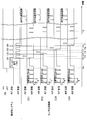
- FIG. 1 is a block diagram showing the overall configuration of the TPMS according to the present embodiment.
- the upward direction in the drawing corresponds to the front of the vehicle 1
- the downward direction in the drawing corresponds to the rear of the vehicle 1.
- the TPMS is attached to the vehicle 1 and includes a sensor transceiver 2 and a vehicle body side system 3.
- one sensor transceiver 2 is attached to each wheel 4a to 4d in the vehicle 1.
- the sensor transceiver 2 basically detects the air pressure of the tires attached to the wheels 4a to 4d and the temperature in the tires while the vehicle 1 is traveling, and frame the detection signal data indicating the detection results. It functions as a transmitter that stores and transmits the data inside.
- the sensor transceiver 2 also functions as a receiver that receives RF radio waves transmitted from the vehicle body side system 3 as will be described later. When the sensor transceiver 2 receives the RF radio wave, the sensor transceiver 2 detects the tire pressure and the temperature in the tire, and stores the data indicating the detection result in the frame for transmission.
- the vehicle body side system 3 is provided on the vehicle body 5 side of the vehicle 1 and receives a frame transmitted from the sensor transceiver 2 and performs various processes and calculations based on the data stored therein. I am looking for tire pressure.
- the vehicle body side system 3 transmits an RF radio wave to the sensor transceiver 2 based on the IG and quickly detects the tire air pressure and the temperature in the tire from the sensor transceiver 2. It is trying to convey.
- the vehicle body side system 3 alerts the user that the tire air pressure is abnormal, thereby alerting the user.
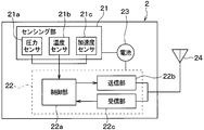
- the sensor transceiver 2 is configured to include a sensing unit 21, a microcomputer 22, a battery 23, and an antenna 24.
- the sensing unit 21 includes a pressure sensor 21a, a temperature sensor 21b, and an acceleration sensor 21c.
- the pressure sensor 21a and the temperature sensor 21b output a detection signal (hereinafter referred to as a detection signal related to the tire pressure) indicating the tire air pressure and the temperature in the tire, and each detection signal is output to the microcomputer 22.
- a detection signal related to the tire pressure hereinafter referred to as a detection signal related to the tire pressure
- the acceleration sensor 21 c outputs an acceleration detection signal including an acceleration component in the radial direction of each of the wheels 4 a to 4 d, that is, an acceleration component in the centrifugal direction, and inputs it to the microcomputer 22. ing.
- the sensing unit 21 detects acceleration for each predetermined detection cycle based on a command from the microcomputer 22. In addition, the sensing unit 21 detects the tire air pressure and the temperature in the tire for each predetermined periodic transmission period during a period in which the vehicle 1 continues to travel after receiving a command from the microcomputer 22.
- the microcomputer 22 is a well-known computer having a CPU, ROM, RAM, I / O, and the like, and executes predetermined processing according to a program stored in the ROM.
- the microcomputer 22 includes a control unit 22a, a transmission unit 22b, a reception unit 22c, and the like, and performs various processes related to tire pressure monitoring according to a program stored in a built-in memory of the control unit 22a. Yes.
- the control unit 22a corresponds to the first control unit.
- the RF radio wave transmitted from the vehicle body side system 3 when the IG is turned on is detected.
- the receiving unit 22c is set in a standby state in which the RF radio wave can be received so that the transceiver 2 can receive the signal.
- the control unit 22a places the receiving unit 22c in a standby state in which the RF radio wave can be received, for example, at predetermined intervals so that the RF radio wave can be received intermittently.
- the vehicle body side system 3 first sends a burst signal for making the receiving unit 22c of each sensor transceiver 2 continuously receive RF radio waves as RF radio waves. Subsequently, the vehicle body side system 3 requests transmission of data indicating the detection result of the tire pressure and the temperature in the tire (hereinafter, data related to the tire pressure) to each sensor transceiver 2 as an RF radio wave. A signal is sent.
- the control unit 22a maintains the reception unit 22c in a standby state in which the RF radio wave can be received, and continues that state until the request signal arrives. More specifically, the request signal stores unique identification information (hereinafter referred to as ID information) of each sensor transceiver 2 and includes a request signal including the ID information of each sensor transceiver 2 in order at different timings. Output from the vehicle body side system 3. For this reason, the control unit 22a of each sensor transceiver 2 keeps the receiving unit 22c in a standby state in which the RF radio wave can be continuously received until the request signal including its own ID information is received. When it arrives, the standby state is canceled.
- ID information unique identification information
- control unit 22a times out and returns the reception unit 22c to the standby state in which the RF signal can be received intermittently again.
- control part 22a will perform the process for transmitting the data regarding tire pressure toward the vehicle body side system 3 as a response, if the request signal containing own ID information is received. Specifically, the control unit 22a receives a detection signal related to the tire air pressure from the sensing unit 21, processes the signal and processes it as necessary, and processes the detection result as data related to the tire air pressure. Together with the ID information. Then, the frame is sent to the transmission unit 22b.
- the control unit 22a performs different operations depending on whether or not the vehicle 1 is running. That is, since it is desired to detect the tire air pressure during traveling, the control unit 22a causes the sensing unit 21 to detect the tire air pressure and the temperature in the tire every predetermined periodic transmission cycle, and based on the tire air pressure data based on the tire air pressure data. Processing to create and send to the transmission unit 22b is performed. Conversely, the need for tire pressure detection is not high while the vehicle is stopped. Further, the sensor transceiver 2 cannot grasp whether the IG is on or off.
- the control unit 22a basically enters a sleep state, wakes up at predetermined intervals, and puts the reception unit 22c into a standby state in which RF radio waves can be received. As with IG off, RF radio waves can be received intermittently. Whether or not the vehicle 1 is traveling can be detected based on the detection signal of the acceleration sensor 21c.
- the transmission unit 22b corresponds to a first transmission unit, and functions as an output unit that transmits the frame transmitted from the control unit 22a to the vehicle body side system 3 through the antenna 24.
- the transmission unit 22b constitutes an RF transmission unit that performs frame transmission using RF radio waves.
- the receiving unit 22c corresponds to a first receiving unit, and functions as an input unit that receives an RF radio wave transmitted from the vehicle body side system 3 through the antenna 24.
- the receiving unit 22c receives the signal and transmits it to the control unit 22a.
- the receiving unit 22c is normally in a state where it cannot receive RF radio waves, but enters a standby state in which RF radio waves can be received according to a request from the control unit 22a.
- the transmission part 22b and the receiving part 22c are described as a separate functional block here, it becomes possible to make these common. That is, the function of transmitting and receiving RF radio waves can be realized by the same structure. For this reason, the transmission part 22b and the reception part 22c can be comprised as one transmission / reception part, and a low-cost system is realizable. Of course, even if the transmitting unit 22b and the receiving unit 22c are configured separately, the antenna 24 can be shared, so that even in that case, a low-cost system can be realized.
- the battery 23 supplies power to the control unit 22a and the like, and receives power supply from the battery 23, collects data related to tire pressure in the sensing unit 21, detects acceleration, and controls the control unit 22a. Various calculations are executed. Since the sensor transceiver 2 is provided in the tire, replacement of the battery 23 is not easy, and it is necessary to suppress current consumption. For this reason, it is effective to be able to suppress current consumption by shortening the period during which the receiving unit 22c is operated as described above.
- the antenna 24 receives RF radio waves transmitted from the vehicle body side system 3 and transmits RF radio waves to the vehicle body side system 3. Since RF radio waves are transmitted and received, the antenna 24 may be configured separately for LF radio wave transmission and RF radio wave transmission. However, by using a single antenna, the cost can be reduced by reducing the number of components. be able to.
- the sensor transceiver 2 configured in this manner is attached to an air injection valve in each of the wheels 4a to 4d, for example, and is arranged so that the sensing unit 21 is exposed inside the tire.
- the tire air pressure of the corresponding wheel is detected, and a frame storing data related to the tire air pressure is transmitted through the antenna 24 provided in each sensor transceiver 2.
- the tire air pressure of the corresponding wheel is detected, and data relating to the tire air pressure is stored every predetermined periodic transmission cycle, for example, every minute through the antenna 24 provided in each sensor transceiver 2. Send the frame.
- the data relating to the tire pressure is sent together with the ID information of each sensor transceiver 2 provided in the vehicle.
- the position of each wheel can be specified by a known wheel position detection device that detects which position of the vehicle the wheel is attached to. For this reason, it is possible to determine which wheel data is transmitted by transmitting data related to the tire pressure together with the ID information to the transceiver 30.
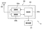
- the vehicle body side system 3 is configured to include a transceiver 30 and a notification device 31.
- Each part which comprises the vehicle body side system 3 is connected through in-vehicle LAN (abbreviation of Local * AreaNetwork) by CAN (abbreviation of Controller
- in-vehicle LAN abbreviation of Local * AreaNetwork
- CAN abbreviation of Controller
- the transceiver 30 is configured to include an antenna 32 and a microcomputer 33.
- the antenna 32 outputs burst signals and request signals as RF radio waves to the sensor transceivers 2 and receives frames transmitted as RF radio waves from the sensor transceivers 2.
- the antenna 32 is fixed to the vehicle body 5. Yes. Since both transmission and reception are performed using RF radio waves, the antenna 32 is shared for RF radio wave transmission and RF radio wave reception, so that a low-cost system can be realized by reducing the number of components. Yes.
- the microcomputer 33 is a well-known computer having a CPU, ROM, RAM, I / O, and the like, and executes predetermined processing according to a program stored in the ROM.
- the microcomputer 33 includes a transmission unit 33a, a reception unit 33b, and a control unit 33c, and performs various processes related to tire pressure monitoring according to a program stored in a built-in memory of the control unit 33c.
- the transmission unit 33a corresponds to a second transmission unit, and functions as an output unit that transmits a burst signal and a request signal as an RF radio wave through the antenna 32.
- the transmission unit 33a transmits a burst signal or a request signal as an RF radio wave through the antenna 32 in accordance with an instruction from the control unit 33c.
- an instruction to output a burst signal is issued from the control unit 33c to the transmission unit 33a, and accordingly, the burst signal is transmitted from the transmission unit 33a as an RF radio wave.
- the request signal is transmitted as an RF radio wave from the transmission unit 33a accordingly.
- the request signal also includes ID information of each sensor transceiver 2, and the request signal including the ID information of each sensor transceiver 2 in order is transmitted from the control unit 33c at different timings, and the transmission unit 33a. Transmits it in turn to each sensor transceiver 2.
- the receiving unit 33b corresponds to a second receiving unit, and functions as an input unit that inputs a frame from each sensor transceiver 2 received by the antenna 32 and sends the frame to the control unit 33c.
- the control unit 33c corresponds to a second control unit, and obtains tire air pressure by performing various signal processing and calculations based on data related to tire air pressure stored in the received frame, and tire air pressure is calculated based on the tire air pressure. Determining a decrease in Specifically, the control unit 33c compares the tire air pressure with an alarm threshold value, and determines that the tire air pressure is decreased when the tire air pressure becomes equal to or lower than the alarm threshold value. And if the fall of tire air pressure is detected, control part 33c will output the signal to that effect to informing device 31. As a result, the notification device 31 is informed that the tire pressure of any of the wheels 4a to 4d has decreased.
- the control unit 33c instructs the transmission unit 33a to output a burst signal.
- a burst signal is output as an RF radio wave from the transmission unit 33a through the antenna 32, and the reception unit 22c of each sensor transceiver 2 is ready to receive the RF radio wave.
- the control unit 33c outputs a request signal instructing each sensor transceiver 2 to transmit data related to the tire pressure in order. That is, the request signal is transmitted a number of times corresponding to the number of wheels 4a to 4d, and the ID information of each sensor transceiver 2 is included in each request signal in order.
- data relating to tire pressure is sent from each sensor transceiver 2 to the transceiver 30 to determine a decrease in tire air pressure of each wheel 4a-4d. ing.
- the notification device 31 is disposed at a place where a driver who is a user can visually recognize the vehicle while driving, for example, in an instrument panel in the vehicle 1.
- the notification device 31 is composed of, for example, a meter display, a warning lamp, and the like.
- a notification signal instructing notification of a decrease in tire air pressure is sent from the control unit 33c in the transceiver 30, a notification to that effect is displayed. To inform the driver of the decrease in tire pressure.
- the TPMS in this embodiment is configured. Subsequently, an operation example of the TPMS configured as described above will be described. However, in the operation of the TPMS, various processes performed by the sensor transceiver 2 for periodic transmission and determination of a decrease in tire air pressure performed when the transceiver 30 receives a frame that has been transmitted periodically are conventional and It is the same. For this reason, here, the processing when the IG is switched from off to on will be mainly described with reference to FIGS. 4A, 4B, 5 and 6. FIG.
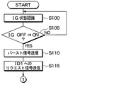
- control unit 33c executes the start-up detection process shown in FIGS. 4A and 4B for each predetermined control period.
- ID information of each sensor transceiver 2 attached to each of the wheels 4a to 4d will be simply described as ID1 to ID4.
- step S100 an IG state recognition process is performed. Thereby, it is recognized whether IG is on or off. Subsequently, the process proceeds to step S105, where it is determined whether or not the IG has been switched from OFF to ON. When the IG has been switched from OFF to ON, the process proceeds to step S110, and the IG continues to be on after the IG is switched off or off to on. When in the middle state, the process returns to step S100.
- step S110 the transmission unit 33a is instructed to transmit a burst signal. Thereby, a burst signal is transmitted from the transmission unit 33a through the antenna 32.
- each sensor transceiver 2 is ready to receive RF radio waves.
- step S115 the transmission unit 33a is instructed to transmit a request signal to the sensor transceiver 2 of ID1. Accordingly, a request signal including ID1 as ID information is transmitted from the transmission unit 33a through the antenna 32.
- the sensor transceiver 2 of ID1 transmits a frame in which data relating to tire pressure is stored together with its own ID information in response.
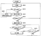
- step S120 it is determined whether or not there is a normal response from the sensor transceiver 2 of ID1.
- a response from the sensor transceiver 2 of ID1 when there is a response from the sensor transceiver 2 of ID1, and a frame including ID information of ID1 is received, an affirmative determination is made in step S120. If the frame is not received or if there is any abnormal response from the sensor transceiver 2 of ID1, a negative determination is made.
- the abnormal response is a response that is performed when the sensor transceiver 2 cannot normally transmit data related to tire pressure due to, for example, a failure of the sensing unit 21. In that case, a frame indicating an abnormal response is transmitted from the sensor transceiver 2 so that the controller 33c can confirm that it is an abnormal response.
- step S120 If an affirmative determination is made in step S120, the process proceeds to step S125 and step S130, and this time, the same operation as that for the sensor transceiver 2 of ID1 is performed on the sensor transceiver 2 of ID2. That is, by instructing the transmitter 33a to transmit a request signal to the sensor transceiver 2 of ID2, the transmitter 33a transmits a request signal including ID2 through the antenna 32, and then from the sensor transceiver 2 of ID2 It is determined whether there is a normal response. Also here, if there is a normal response from the sensor transceiver 2 of ID2, an affirmative determination is made, and if not, a negative determination is made.
- step S130 If an affirmative determination is made in step S130, the process proceeds to step S135 and step S140, and this time, the same operation as that for the sensor transceiver 2 of ID1 is performed on the sensor transceiver 2 of ID3.
- step S140 an affirmative determination is made if there is a normal response from the sensor transceiver 2 of ID3, and a negative determination is made if there is no response.
- step S140 when an affirmative determination is made in step S140, the process proceeds to step S145 and step S150, and finally, the same processing as that of the sensor transceiver 2 of ID1 is performed on the sensor transceiver 2 of ID4.
- step S150 an affirmative determination is made if there is a normal response from the sensor transceiver 2 of ID4, and a negative determination is made if there is no response. If an affirmative determination is made here as well, the process proceeds to step S155, and the recognition of the tire pressure is completed for all the sensor transceivers 2 of ID1 to ID4, and the process is terminated.
- steps S120, S130, S140, and S150 the process proceeds to steps S160, S170, S180, and S190, respectively, to determine whether or not there is an abnormal response. If there is an abnormal response, the tire air pressure cannot be detected, so the process is terminated. In this case, for example, a signal indicating that the tire pressure cannot be detected may be sent to the notification device 31 to notify the user that the tire pressure cannot be detected through the notification device 31.
- steps S165, S175, S185, and S195 respectively, and it is determined whether or not a TIME OUT has elapsed after a predetermined time without any response. If the determination is affirmative, the process is terminated. If the determination is negative, the process returns to steps S120, S130, S140, and S150, and the process is repeated.
- the above processing is performed. Then, when the recognition of the tire pressure of each wheel 4a to 4d is completed, it is determined whether or not the tire pressure is reduced. Instructs the tire pressure drop notification. Thereby, it is possible to notify the user of a decrease in tire air pressure through the notification device 31.
- the control unit 22a executes the sensor response process shown in FIG. 5 for each predetermined control period.
- step S200 acceleration is recognized from the detection signal of the acceleration sensor 21c as acceleration recognition processing. And it progresses to step S210 and it is determined whether the driving
- the detection signal of the acceleration sensor 21c includes the acceleration component in the centrifugal direction based on the rotation of the wheels 4a to 4d to which the sensor transceiver 2 is attached in addition to the gravitational acceleration. If the acceleration component in the centrifugal direction is recognized as the traveling acceleration G as the acceleration component in the centrifugal direction, the traveling acceleration G is recognized. If a negative determination is made in step S210, the process proceeds to step S220, and intermittent RF reception processing is performed. That is, the control unit 22a places the receiving unit 22c in a standby state in which RF radio waves can be received intermittently.
- step S230 it is determined whether or not reception of an RF radio wave, specifically, a burst signal has been received, and the processes of steps S200 to S220 are repeated until reception is received. Proceed to step S240.
- step S240 continuous RF reception processing is performed. That is, the control unit 22a places the receiving unit 22c in a standby state in which the RF radio wave can be continuously received. As a result, the receiving unit 22c enters a standby state in which the RF radio wave can be continuously received until the request signal arrives. Thereafter, in step S250, it is determined whether or not a request signal including its own ID information has been received. If it has been received, the process proceeds to step S260. As a response to the request signal, data relating to tire pressure is received as its ID information. The frame stored together with this is transmitted as an RF radio wave.
- step S270 it is determined whether a TIME OUT has elapsed after a predetermined time has elapsed without receiving the request signal. Then, the processes in steps S240 and S250 are repeated until TIME OUT, and when TIME OUT, the process is terminated and the process is repeated from step S200.
- step S210 determines whether an affirmative determination is made in step S210 or not. If an affirmative determination is made in step S210, the process proceeds to step S280, and the periodic RF transmission mode during traveling is set.
- periodic transmission is performed in which a frame in which data related to tire air pressure is stored together with its own ID information is transmitted every predetermined periodic transmission cycle.
- FIG. 6 is a time chart when the above operation is performed.
- each sensor transceiver 2 when the IG before time ta is off, each sensor transceiver 2 is in a standby state in which RF radio waves can be received intermittently.
- a standby state is established in which RF radio waves can be received every predetermined period T that is shorter than the transmission time TB of the burst signal, and RF radio waves can be received during the period t.
- the current consumption during this period t is, for example, 12 mA.
- a burst signal is transmitted as an RF radio wave from the transceiver 30 of the vehicle body side system 3.
- each sensor transceiver 2 is in a standby state in which it can receive RF radio waves with its own ID information, that is, a period until a request signal arrives. become.
- the vehicle body side system 3 After that, at time tb, the vehicle body side system 3 outputs a request signal of ID1, and then enters a standby state in which the RF radio wave can be received so that the RF radio wave as a response from the sensor transceiver 2 can be received.
- the sensor transmitter / receiver 2 of ID1 cancels the state in which the RF radio wave can be received in response to the request signal, and transmits a frame including data related to tire pressure as a response to the request signal at time tc.
- an ID2 request signal is output from the vehicle body side system 3 at the time point td
- the same operation as described above is performed, and a frame including data related to tire air pressure is transmitted from the ID2 sensor transmitter at the time point te.
- an ID3 request signal is output from the vehicle body side system 3 at time tf
- a frame including data related to tire pressure is transmitted from the ID3 sensor transmitter at time tg.
- the request signal of ID4 is output from the vehicle body side system 3 at the time point th, a frame including data relating to tire air pressure is transmitted from the sensor transmitter of ID4 at the time point ti.
- each sensor transceiver 2 in response to the request signal from the vehicle body side system 3, the frame including the data related to the tire pressure is sent from each of the sensor transceivers ID 1 to ID 4 and is received by the vehicle body side system 3.
- the tire pressure of each wheel 4a to 4d is detected. Accordingly, it is possible to detect the tire air pressure of each of the wheels 4a to 4d immediately after the IG is switched from on to off.
- each sensor transceiver 2 since each sensor transceiver 2 is in a standby state in which RF radio waves can be received intermittently rather than continuously, it is possible to reduce current consumption. Since each sensor transceiver 2 has a period T at which RF radio waves can be received intermittently shorter than the burst signal transmission time, each sensor transceiver 2 can reliably receive the burst signal. It becomes.
- each sensor transceiver 2 enters a standby state in which the RF radio wave can be intermittently received again from the time point tj after a predetermined time has elapsed. Then, when the traveling acceleration G is recognized, the periodic RF transmission mode in which data relating to the tire pressure is transmitted every periodic transmission cycle is set.
- the sensor transceiver 2 is intermittently capable of receiving RF radio waves. Further, when a burst signal is sent as RF radio waves from the vehicle body side system 3, the sensor transceiver 2 is continuously ready to receive RF radio waves. When the sensor transceiver 2 can receive the RF radio wave, the tire pressure can be detected earlier by transmitting the data related to the tire pressure to the vehicle body system 3 based on the request signal from the vehicle body system 3. It becomes possible.
- the sensor transmitter / receiver 2 Before receiving the burst signal, the sensor transmitter / receiver 2 is in a standby state in which the RF radio wave can be received and is only intermittently performed. Therefore, current consumption can be reduced. Become. Furthermore, it is not necessary to provide an antenna or the like for transmitting LF radio waves near each wheel.
- a TPMS capable of detecting tire air pressure earlier can be achieved while suppressing an increase in current consumption.
- the TPMS described here is designed to promptly detect the tire air pressure when it is detected that the vehicle 1 may start.
- the vehicle 1 for example, the case where the IG is switched from OFF to ON is taken as an example, but at least 1 including other conditions described below is included.
- a smart key system registered trademark
- a smart key registered trademark
- the electronic key is authenticated as being within a predetermined authentication range from the door, it may be detected that the vehicle may start.
- the transmitter / receiver 30 of the vehicle body side system 3 is provided with a transmitter 33a and a receiver 33b capable of transmitting and receiving RF radio waves.
- a configuration capable of performing transmission and reception of RF radio waves, that is, bidirectional communication bidirectional communication with the sensor transceiver 2 is performed there.
- parts can be shared and the number of parts can be further reduced.
- the vehicle 1 since the vehicle 1 includes a system that performs bidirectional communication with the electronic key, it is also possible to perform bidirectional communication with the sensor transceiver 2 using the system. .
- the IG is described as an example of the start switch that is operated when the vehicle 1 is started, but this is an example in which the present disclosure is applied to an internal combustion engine vehicle.
- the start switch is not always IG.
- the start switch may be configured by a push switch or the like, and the present disclosure can be applied to such a case.
Abstract
A sensor transceiver (2) is brought into a state in which it is possible to receive intermittent RF signals. In addition, in response to a burst signal transmitted as an RF signal from a vehicle-side system (3), the sensor transceiver (2) is brought into a state in which continuous reception of RF signals is enabled. After becoming able to receive the RF signals, the sensor transceiver (2) transmits data about tire pressure to the vehicle-side system (3) on the basis of a request signal from the vehicle-side system (3), thereby enabling earlier detection of the tire pressure.
Description
本出願は、2016年9月6日に出願された日本特許出願番号2016-173734号に基づくもので、ここにその記載内容が参照により組み入れられる。
This application is based on Japanese Patent Application No. 2016-173734 filed on September 6, 2016, the description of which is incorporated herein by reference.
本開示は、タイヤ空気圧監視システム(以下、TPMS:Tire PressureMonitoringSystemという)に関するものである。
The present disclosure relates to a tire pressure monitoring system (hereinafter referred to as TPMS: Tire Pressure Monitoring System).
従来より、タイヤ空気圧監視システムの1つとしてダイレクト式のものがある(例えば、特許文献1参照)。このタイプのTPMSでは、タイヤが取り付けられた車輪側に、圧力センサ等が備えられたセンサ送信機が直接取り付けられている。また、車両側には、アンテナおよび受信機が備えられており、圧力センサ等での検出結果がセンサ送信機から送信されると、アンテナを介して受信機でその検出信号が受信され、タイヤ空気圧検出が行われる。
Conventionally, there is a direct type as one of tire pressure monitoring systems (for example, see Patent Document 1). In this type of TPMS, a sensor transmitter equipped with a pressure sensor or the like is directly attached to a wheel side to which a tire is attached. In addition, an antenna and a receiver are provided on the vehicle side. When a detection result from a pressure sensor or the like is transmitted from the sensor transmitter, the detection signal is received by the receiver via the antenna, and the tire pressure Detection is performed.
しかしながら、上記のTPMSでは、車両におけるイグニッションスイッチ(以下、IGという)のオン中にしかタイヤ空気圧の検出を行わない。このため、IGオン直後には駐車前に収集した空気圧情報しかなく、IGオフ中の空気圧情報に基づいてタイヤ空気圧を検出することができない。ところが、車両の停止中においても、タイヤ空気圧の自然減やパンクによるタイヤ空気圧の減少も発生し得る。そのため、IGオン後に、できるだけ早くタイヤ空気圧の検出が行われることが望まれる。
However, in the above TPMS, the tire pressure is detected only while the ignition switch (hereinafter referred to as IG) in the vehicle is on. For this reason, there is only air pressure information collected before parking immediately after the IG is turned on, and the tire pressure cannot be detected based on the air pressure information during the IG off. However, even when the vehicle is stopped, the tire pressure may be reduced naturally or the tire pressure may be reduced due to puncture. Therefore, it is desired that the tire air pressure is detected as soon as possible after the IG is turned on.
これに対して、各タイヤの近くにLF(Low Frequencyの略)電波を送信できるアンテナをそれぞれ配置する構成としたTPMSもある。このTPMSでは、IGオン後に各アンテナからLF電波を送信させ、各タイヤに備えられたセンサ送信機に受信させることでセンサ送信機からタイヤ空気圧のデータを送信させる。しかし、各車輪の近くにLF電波を送信できるアンテナを設置したり、LF電波を送信させるためのLF送信ドライバが必要になるなど、部品点数の増加を招き、高コストなシステムになる。
On the other hand, there is also a TPMS in which an antenna capable of transmitting LF (abbreviation of Low Frequency) is arranged near each tire. In this TPMS, after the IG is turned on, LF radio waves are transmitted from each antenna and are received by a sensor transmitter provided in each tire, thereby transmitting tire pressure data from the sensor transmitter. However, an antenna capable of transmitting LF radio waves is installed near each wheel, and an LF transmission driver for transmitting LF radio waves is required, resulting in an increase in the number of components and a high-cost system.
このため、本発明者らは、LF電波の代わりに、RF(Radio Frequencyの略)電波を利用して、IGオン後にセンサ送信機にRF電波を送るようにすることについて検討を行った。RF電波は、各センサ送信機からタイヤ空気圧などの検出結果を送る際に用いられている。したがって、各センサ送信機には既にRF送信を行う送信部やアンテナが備えられている。それに加えて、RF送信を行う送信部やRF受信を行う受信部さらにはアンテナについては共通化が可能なものである。このため、RF送信を行う送信部とRF受信を行う受信部の共通化、もしくは送信用と受信用のアンテナの共通化等により、部品点数の増加を抑制でき、低コストなシステムの実現が可能になる。ところが、RF受信を常に行えるようにすると、RF電波が高周波であるために消費電流が増大してしまう。センサ送信機はタイヤ内に備えられていて車体から隔離されているため、電池寿命の観点からも消費電流の低減が必須であり、単にRF電波を利用してIGオン後にセンサ送信機にRF電波を送るようにしたのでは、電池寿命の低下を招いてしまう。
For this reason, the present inventors examined using RF (abbreviation of Radio 電波 Frequency) radio waves instead of LF radio waves to send RF radio waves to the sensor transmitter after IG is turned on. RF radio waves are used when sending detection results such as tire pressure from each sensor transmitter. Therefore, each sensor transmitter is already provided with a transmitter and an antenna that perform RF transmission. In addition, the transmitter that performs RF transmission, the receiver that performs RF reception, and the antenna can be shared. For this reason, an increase in the number of parts can be suppressed by sharing a transmitter for RF transmission and a receiver for RF reception, or by sharing antennas for transmission and reception, and a low-cost system can be realized. become. However, if the RF reception can always be performed, the current consumption increases because the RF radio wave has a high frequency. Since the sensor transmitter is installed in the tire and isolated from the vehicle body, it is essential to reduce current consumption from the viewpoint of battery life. Simply use RF radio waves and turn on the RF radio waves to the sensor transmitter after IG is turned on. If this is done, the battery life will be reduced.
本開示は、各車輪の近くにLF電波を送信するためのアンテナなどを備えなくても良く、かつ、消費電流の増大を抑制しつつ、車両が発進する可能性があるときにより早くからタイヤ空気圧を検出することが可能なTPMSを提供することを目的とする。
In the present disclosure, it is not necessary to provide an antenna for transmitting LF radio waves in the vicinity of each wheel, and it is possible to reduce the tire pressure from an earlier time when the vehicle may start while suppressing an increase in current consumption. An object is to provide a TPMS that can be detected.
本開示の1つの観点におけるTPMSは、複数の車輪それぞれに設けられ、該複数の車輪それぞれのタイヤ空気圧を検出するセンシング部と、タイヤ空気圧に関するデータを格納したフレームを作成する第1制御部と、第1制御部が作成したフレームをRF電波として送信する第1送信部と、RF電波を受信する第1受信部と、を有するセンサ送受信機と、車体側に設けられ、センサ送受信機から送信されたフレームを受信する第2受信部と、受信したフレームに基づいて複数の車輪それぞれのタイヤ空気圧を検出すると第2制御部と、第1受信部に受信させるRF電波を送信する第2送信部と、を有する車体側システムと、を備えている。このような構成において、車体側システムでは、第2制御部にて車両が発進する可能性があることを検出すると、RF電波として、センサ送受信機に対して第1受信部が連続的にRF電波を受信可能な状態にするためのバースト信号を出力したのちフレームの送信を要求するリクエスト信号を出力する。そして、センサ送受信機では、第2制御部は、第1受信部を間欠的にRF電波が受信可能な待機状態にすると共に、第1受信部が間欠的にRF電波を受信可能な待機状態となっているときにバースト信号を受信すると、第1受信部を連続的にRF電波を受信可能な状態としてリクエスト信号を受信させ、リクエスト信号が受信されると応答してフレームの送信を行う。
The TPMS in one aspect of the present disclosure is provided in each of a plurality of wheels, a sensing unit that detects tire pressure of each of the plurality of wheels, a first control unit that creates a frame that stores data related to the tire pressure, A sensor transceiver having a first transmitter for transmitting a frame created by the first controller as an RF radio wave, and a first receiver for receiving the RF radio wave, and provided on the vehicle body side and transmitted from the sensor transceiver. A second receiving unit that receives the received frame, a second control unit that detects the tire pressure of each of the plurality of wheels based on the received frame, and a second transmitting unit that transmits an RF radio wave to be received by the first receiving unit. And a vehicle body side system. In such a configuration, in the vehicle body side system, when the second control unit detects that the vehicle may start, the first receiving unit continuously transmits the RF radio wave as an RF radio wave to the sensor transceiver. A request signal for requesting transmission of a frame is output after outputting a burst signal for enabling reception of a frame. In the sensor transceiver, the second control unit sets the first receiving unit in a standby state in which the RF radio wave can be intermittently received, and sets the first receiving unit in a standby state in which the first receiving unit can intermittently receive the RF radio wave. If a burst signal is received while the signal is being received, the first reception unit is made to be able to continuously receive RF radio waves, and the request signal is received. When the request signal is received, a frame is transmitted in response.
このように、センサ送受信機を間欠的にRF電波が受信可能な状態にしている。また、車体側システムからRF電波としてバースト信号が送られてくると、それに伴ってセンサ送受信機を連続的にRF電波の受信が行える状態となるようにしている。そして、センサ送受信機がRF電波を受信できるようになると、車体側システムからのリクエスト信号に基づいてタイヤ空気圧に関するデータを車体側システムに伝えることで、より早くからタイヤ空気圧を検出することが可能となる。
Thus, the sensor transceiver is in a state in which RF radio waves can be received intermittently. In addition, when a burst signal is transmitted as RF radio waves from the vehicle body side system, the sensor transceiver is configured to be able to continuously receive RF radio waves accordingly. When the sensor transceiver can receive RF radio waves, the tire pressure can be detected earlier by transmitting data related to the tire pressure to the vehicle body system based on the request signal from the vehicle body system. .
このとき、バースト信号を受信する前には、センサ送受信機をRF電波の受信可能な待機状態としつつも、それを間欠的にしか行っていないため、消費電流の低減を図ることが可能となる。さらに、各車輪の近くにLF電波を送信するためのアンテナなどを備える必要も無い。
At this time, before the burst signal is received, the sensor transceiver is set in a standby state in which the RF radio wave can be received, but is only intermittently performed. Therefore, it is possible to reduce current consumption. . Furthermore, it is not necessary to provide an antenna or the like for transmitting LF radio waves near each wheel.
したがって、各車輪の近くにLF電波を送信するためのアンテナなどを備えなくても、消費電流の増大を抑制しつつ、より早くからタイヤ空気圧を検出することが可能なTPMSとすることができる。
Therefore, even if an antenna for transmitting LF radio waves is not provided near each wheel, a TPMS capable of detecting tire air pressure earlier can be achieved while suppressing an increase in current consumption.
以下、本開示の実施形態について図に基づいて説明する。なお、以下の各実施形態相互において、互いに同一もしくは均等である部分には、同一符号を付して説明を行う。
Hereinafter, embodiments of the present disclosure will be described with reference to the drawings. In the following embodiments, parts that are the same or equivalent to each other will be described with the same reference numerals.
(第1実施形態)
第1実施形態について、図1~図6を参照して説明する。なお、図1は、本実施形態にかかるTPMSの全体構成を示すブロック図であるが、図1の紙面上方向が車両1の前方、紙面下方向が車両1の後方に一致する。 (First embodiment)
A first embodiment will be described with reference to FIGS. FIG. 1 is a block diagram showing the overall configuration of the TPMS according to the present embodiment. In FIG. 1, the upward direction in the drawing corresponds to the front of thevehicle 1, and the downward direction in the drawing corresponds to the rear of the vehicle 1.
第1実施形態について、図1~図6を参照して説明する。なお、図1は、本実施形態にかかるTPMSの全体構成を示すブロック図であるが、図1の紙面上方向が車両1の前方、紙面下方向が車両1の後方に一致する。 (First embodiment)
A first embodiment will be described with reference to FIGS. FIG. 1 is a block diagram showing the overall configuration of the TPMS according to the present embodiment. In FIG. 1, the upward direction in the drawing corresponds to the front of the
図1に示されるように、TPMSは、車両1に取り付けられるもので、センサ送受信機2や車体側システム3を備えて構成されている。
As shown in FIG. 1, the TPMS is attached to the vehicle 1 and includes a sensor transceiver 2 and a vehicle body side system 3.
図1に示されるように、センサ送受信機2は、車両1における各車輪4a~4dに1つずつ取り付けられる。センサ送受信機2は、基本的には、車両1の走行中に、車輪4a~4dに取り付けられたタイヤの空気圧やタイヤ内の温度を検出すると共に、その検出結果を示す検出信号のデータをフレーム内に格納して送信する送信機として機能する。また、センサ送受信機2は、後述するように車体側システム3から送信されるRF電波を受信する受信機としても機能する。そして、センサ送受信機2は、RF電波を受信したときにも、タイヤ空気圧やタイヤ内の温度を検出して、その検出結果を示すデータをフレーム内に格納して送信するようになっている。
As shown in FIG. 1, one sensor transceiver 2 is attached to each wheel 4a to 4d in the vehicle 1. The sensor transceiver 2 basically detects the air pressure of the tires attached to the wheels 4a to 4d and the temperature in the tires while the vehicle 1 is traveling, and frame the detection signal data indicating the detection results. It functions as a transmitter that stores and transmits the data inside. The sensor transceiver 2 also functions as a receiver that receives RF radio waves transmitted from the vehicle body side system 3 as will be described later. When the sensor transceiver 2 receives the RF radio wave, the sensor transceiver 2 detects the tire pressure and the temperature in the tire, and stores the data indicating the detection result in the frame for transmission.
一方、車体側システム3は、車両1における車体5側に備えられ、センサ送受信機2から送信されるフレームを受信すると共に、その中に格納されたデータに基づいて各種処理や演算等を行うことでタイヤ空気圧を求めている。また、車体側システム3は、図示しないIGがオンされると、それに基づいてセンサ送受信機2に対してRF電波を送信し、センサ送受信機2から早急にタイヤ空気圧やタイヤ内の温度の検出結果を伝えさせるようにしている。そして、車体側システム3では、タイヤ空気圧が異常になっていると、ユーザに対して報知することで、注意を促す。
On the other hand, the vehicle body side system 3 is provided on the vehicle body 5 side of the vehicle 1 and receives a frame transmitted from the sensor transceiver 2 and performs various processes and calculations based on the data stored therein. I am looking for tire pressure. In addition, when the IG (not shown) is turned on, the vehicle body side system 3 transmits an RF radio wave to the sensor transceiver 2 based on the IG and quickly detects the tire air pressure and the temperature in the tire from the sensor transceiver 2. It is trying to convey. The vehicle body side system 3 alerts the user that the tire air pressure is abnormal, thereby alerting the user.
図2および図3を参照して、これらセンサ送受信機2および車体側システム3の詳細構成について説明する。
Detailed configurations of the sensor transceiver 2 and the vehicle body side system 3 will be described with reference to FIGS.
図2に示されるように、センサ送受信機2は、センシング部21、マイクロコンピュータ22、電池23およびアンテナ24を備えた構成とされている。
As shown in FIG. 2, the sensor transceiver 2 is configured to include a sensing unit 21, a microcomputer 22, a battery 23, and an antenna 24.
センシング部21は、圧力センサ21aや温度センサ21bおよび加速度センサ21cを備えた構成とされている。このため、センシング部21では、圧力センサ21aや温度センサ21bにて、タイヤ空気圧やタイヤ内の温度を示す検出信号(以下、タイヤ空気圧に関する検出信号という)を出力し、各検出信号をマイクロコンピュータ22に入力する。また、センシング部21では、加速度センサ21cにて、各車輪4a~4dそれぞれの径方向の加速度成分、つまり遠心方向の加速度成分を含む加速度の検出信号を出力し、それをマイクロコンピュータ22に入力している。センシング部21は、マイクロコンピュータ22からの指令に基づいて所定の検出周期毎に加速度を検出している。また、センシング部21は、マイクロコンピュータ22からの指令があってから車両1が走行を継続している期間中、所定の定期送信周期毎にタイヤ空気圧やタイヤ内の温度を検出している。
The sensing unit 21 includes a pressure sensor 21a, a temperature sensor 21b, and an acceleration sensor 21c. For this reason, in the sensing unit 21, the pressure sensor 21a and the temperature sensor 21b output a detection signal (hereinafter referred to as a detection signal related to the tire pressure) indicating the tire air pressure and the temperature in the tire, and each detection signal is output to the microcomputer 22. To enter. In the sensing unit 21, the acceleration sensor 21 c outputs an acceleration detection signal including an acceleration component in the radial direction of each of the wheels 4 a to 4 d, that is, an acceleration component in the centrifugal direction, and inputs it to the microcomputer 22. ing. The sensing unit 21 detects acceleration for each predetermined detection cycle based on a command from the microcomputer 22. In addition, the sensing unit 21 detects the tire air pressure and the temperature in the tire for each predetermined periodic transmission period during a period in which the vehicle 1 continues to travel after receiving a command from the microcomputer 22.
マイクロコンピュータ22は、CPU、ROM、RAM、I/Oなどを備えた周知のもので、ROMなどに記憶されたプログラムにしたがって、所定の処理を実行する。具体的には、マイクロコンピュータ22は、制御部22aや送信部22bおよび受信部22cなどを備えており、制御部22aの内蔵メモリに記憶されたプログラムに従って、タイヤ空気圧監視に関わる各種処理を行っている。
The microcomputer 22 is a well-known computer having a CPU, ROM, RAM, I / O, and the like, and executes predetermined processing according to a program stored in the ROM. Specifically, the microcomputer 22 includes a control unit 22a, a transmission unit 22b, a reception unit 22c, and the like, and performs various processes related to tire pressure monitoring according to a program stored in a built-in memory of the control unit 22a. Yes.
制御部22aは、第1制御部に相当するものであり、IGがオフ中を含めて車両1が停止中には、IGがオンされたときに車体側システム3から送信されるRF電波をセンサ送受信機2で受信できるように、受信部22cをRF電波の受信可能な待機状態にする。ただし、受信部22cを常にRF電波の受信可能な待機状態にしておくと、RF電波が高周波であるために、消費電流の増大を招いてしまう。したがって、間欠的にRF電波を受信可能な待機状態となるように、制御部22aは、例えば所定周期毎に受信部22cをRF電波の受信可能な待機状態にする。
The control unit 22a corresponds to the first control unit. When the vehicle 1 is stopped, including when the IG is off, the RF radio wave transmitted from the vehicle body side system 3 when the IG is turned on is detected. The receiving unit 22c is set in a standby state in which the RF radio wave can be received so that the transceiver 2 can receive the signal. However, if the receiving unit 22c is always in a standby state in which RF radio waves can be received, the RF radio waves are high frequency, which causes an increase in current consumption. Therefore, the control unit 22a places the receiving unit 22c in a standby state in which the RF radio wave can be received, for example, at predetermined intervals so that the RF radio wave can be received intermittently.
具体的には、車体側システム3から、まず、RF電波として、各センサ送受信機2の受信部22cが連続的にRF電波を受信可能な状態にするためのバースト信号が送られてくる。そして、続けて、車体側システム3から、RF電波として、各センサ送受信機2に対してタイヤ空気圧やタイヤ内の温度の検出結果を示すデータ(以下、タイヤ空気圧に関するデータ)の送信を要求するリクエスト信号が送られてくる。
Specifically, the vehicle body side system 3 first sends a burst signal for making the receiving unit 22c of each sensor transceiver 2 continuously receive RF radio waves as RF radio waves. Subsequently, the vehicle body side system 3 requests transmission of data indicating the detection result of the tire pressure and the temperature in the tire (hereinafter, data related to the tire pressure) to each sensor transceiver 2 as an RF radio wave. A signal is sent.
したがって、制御部22aは、バースト信号を受信すると、受信部22cをRF電波の受信可能な待機状態のまま維持し、続けてリクエスト信号が届くまでの間、その状態を維持する。より詳しくは、リクエスト信号には、各センサ送受信機2の固有識別情報(以下、ID情報という)が格納され、タイミングをずらして順番に各センサ送受信機2のID情報が含められたリクエスト信号が車体側システム3より出力される。このため、各センサ送受信機2の制御部22aは、自身のID情報を含むリクエスト信号を受信するまでの間、受信部22cを連続的にRF電波の受信可能な待機状態とし、そのリクエスト信号が届くと待機状態を解除する。勿論、バースト信号と同様の信号をノイズ的に受信してしまい、その後にリクエスト信号が届かない場合もあり得る。このため、リクエスト信号が所定時間届かなければ、制御部22aは、タイムアウトして、受信部22cを再び間欠的にRF信号を受信可能な待機状態に戻すようにすると好ましい。
Therefore, when receiving the burst signal, the control unit 22a maintains the reception unit 22c in a standby state in which the RF radio wave can be received, and continues that state until the request signal arrives. More specifically, the request signal stores unique identification information (hereinafter referred to as ID information) of each sensor transceiver 2 and includes a request signal including the ID information of each sensor transceiver 2 in order at different timings. Output from the vehicle body side system 3. For this reason, the control unit 22a of each sensor transceiver 2 keeps the receiving unit 22c in a standby state in which the RF radio wave can be continuously received until the request signal including its own ID information is received. When it arrives, the standby state is canceled. Of course, there may be a case where the same signal as the burst signal is received in noise and the request signal does not reach after that. For this reason, if the request signal does not reach the predetermined time, it is preferable that the control unit 22a times out and returns the reception unit 22c to the standby state in which the RF signal can be received intermittently again.
そして、制御部22aは、自身のID情報を含むリクエスト信号を受信すると、その応答として、タイヤ空気圧に関するデータを車体側システム3に向けて送信するための処理を行う。具体的には、制御部22aは、センシング部21からのタイヤ空気圧に関する検出信号を受け取り、それを信号処理すると共に必要に応じて加工し、その検出結果をタイヤ空気圧に関するデータとして各センサ送受信機2のID情報と共にフレーム内に格納する。そして、そのフレームを送信部22bに送る。
And the control part 22a will perform the process for transmitting the data regarding tire pressure toward the vehicle body side system 3 as a response, if the request signal containing own ID information is received. Specifically, the control unit 22a receives a detection signal related to the tire air pressure from the sensing unit 21, processes the signal and processes it as necessary, and processes the detection result as data related to the tire air pressure. Together with the ID information. Then, the frame is sent to the transmission unit 22b.
また、IGがオンされてからは、制御部22aは、車両1が走行中で有るか否かに応じて異なる動作を行う。すなわち、走行中にはタイヤ空気圧検出を行いたいため、制御部22aは、所定の定期送信周期毎に、センシング部21にタイヤ空気圧やタイヤ内の温度を検出させ、それに基づいてタイヤ空気圧に関するデータを作成して送信部22bに送る処理を行う。逆に、停車中にはタイヤ空気圧検出の必要性が高くない。また、センサ送受信機2では、IGがオンかオフかを把握できない。このため、車両1が走行中でなければ、制御部22aは、基本的にはスリープ状態となり、所定周期毎にウェイクアップして受信部22cをRF電波の受信可能な待機状態にすることで、IGオフ時と同様、間欠的にRF電波を受信できるようにする。なお、車両1が走行中であるか否かについては、加速度センサ21cの検出信号に基づいて検出できる。
Further, after the IG is turned on, the control unit 22a performs different operations depending on whether or not the vehicle 1 is running. That is, since it is desired to detect the tire air pressure during traveling, the control unit 22a causes the sensing unit 21 to detect the tire air pressure and the temperature in the tire every predetermined periodic transmission cycle, and based on the tire air pressure data based on the tire air pressure data. Processing to create and send to the transmission unit 22b is performed. Conversely, the need for tire pressure detection is not high while the vehicle is stopped. Further, the sensor transceiver 2 cannot grasp whether the IG is on or off. For this reason, if the vehicle 1 is not running, the control unit 22a basically enters a sleep state, wakes up at predetermined intervals, and puts the reception unit 22c into a standby state in which RF radio waves can be received. As with IG off, RF radio waves can be received intermittently. Whether or not the vehicle 1 is traveling can be detected based on the detection signal of the acceleration sensor 21c.
送信部22bは、第1送信部に相当し、アンテナ24を通じて、制御部22aから送られてきたフレームを車体側システム3に向けて送信する出力部としての機能を果たすものである。本実施形態の場合、送信部22bは、RF電波によってフレーム送信を行うRF送信部を構成している。
The transmission unit 22b corresponds to a first transmission unit, and functions as an output unit that transmits the frame transmitted from the control unit 22a to the vehicle body side system 3 through the antenna 24. In the case of this embodiment, the transmission unit 22b constitutes an RF transmission unit that performs frame transmission using RF radio waves.
受信部22cは、第1受信部に相当し、アンテナ24を通じて、車体側システム3から送られてきたRF電波の受信を行う入力部としての機能を果たすものである。受信部22cは、車体側システム3からRF電波としてバースト信号やリクエスト信号が送られてくると、それを受信して制御部22aに伝える。受信部22cは、通常はRF電波の受信を行えない状態になっているが、制御部22aからの要求にしたがってRF電波の受信可能な待機状態となる。
The receiving unit 22c corresponds to a first receiving unit, and functions as an input unit that receives an RF radio wave transmitted from the vehicle body side system 3 through the antenna 24. When a burst signal or a request signal is sent from the vehicle body side system 3 as an RF radio wave, the receiving unit 22c receives the signal and transmits it to the control unit 22a. The receiving unit 22c is normally in a state where it cannot receive RF radio waves, but enters a standby state in which RF radio waves can be received according to a request from the control unit 22a.
なお、ここでは送信部22bと受信部22cを別々の機能ブロックとして記載してあるが、これらについては共通化することが可能となる。すなわち、RF電波の送信と受信の機能は同じ構造によって実現できる。このため、送信部22bと受信部22cとを1つの送受信部として構成することができ、低コストなシステムを実現できる。勿論、送信部22bと受信部22cを別々の構成としても、アンテナ24を共通化させられるため、その場合でも低コストなシステムの実現は可能である。
In addition, although the transmission part 22b and the receiving part 22c are described as a separate functional block here, it becomes possible to make these common. That is, the function of transmitting and receiving RF radio waves can be realized by the same structure. For this reason, the transmission part 22b and the reception part 22c can be comprised as one transmission / reception part, and a low-cost system is realizable. Of course, even if the transmitting unit 22b and the receiving unit 22c are configured separately, the antenna 24 can be shared, so that even in that case, a low-cost system can be realized.
電池23は、制御部22aなどに対して電力供給を行うものであり、この電池23からの電力供給を受けて、センシング部21でのタイヤ空気圧に関するデータの収集や加速度検出、制御部22aでの各種演算などが実行される。センサ送受信機2がタイヤ内に備えられることから、電池23の取替えは容易ではなく、消費電流の抑制が必要となっている。このため、上記したように受信部22cを稼動させる期間を短くできることで、消費電流の抑制を行えることが有効となる。
The battery 23 supplies power to the control unit 22a and the like, and receives power supply from the battery 23, collects data related to tire pressure in the sensing unit 21, detects acceleration, and controls the control unit 22a. Various calculations are executed. Since the sensor transceiver 2 is provided in the tire, replacement of the battery 23 is not easy, and it is necessary to suppress current consumption. For this reason, it is effective to be able to suppress current consumption by shortening the period during which the receiving unit 22c is operated as described above.
アンテナ24は、車体側システム3から送信されてくるRF電波の受信および車体側システム3へのRF電波の送信を行う。RF電波の送受信を行うことから、アンテナ24をLF電波送信用とRF電波送信用に別々のもので構成としても良いが、1つのアンテナで構成することで部品点数の削減による低コスト化を図ることができる。
The antenna 24 receives RF radio waves transmitted from the vehicle body side system 3 and transmits RF radio waves to the vehicle body side system 3. Since RF radio waves are transmitted and received, the antenna 24 may be configured separately for LF radio wave transmission and RF radio wave transmission. However, by using a single antenna, the cost can be reduced by reducing the number of components. be able to.
このように構成されるセンサ送受信機2は、例えば、各車輪4a~4dのホイールにおけるエア注入バルブに取り付けられ、センシング部21がタイヤの内側に露出するように配置される。これにより、IGオン後には、該当車輪のタイヤ空気圧を検出し、各センサ送受信機2に備えられたアンテナ24を通じて、タイヤ空気圧に関するデータを格納したフレームを送信する。また、車両1の走行中にも、該当車輪のタイヤ空気圧を検出し、各センサ送受信機2に備えられたアンテナ24を通じて、所定の定期送信周期毎、例えば1分毎にタイヤ空気圧に関するデータを格納したフレームを送信する。
The sensor transceiver 2 configured in this manner is attached to an air injection valve in each of the wheels 4a to 4d, for example, and is arranged so that the sensing unit 21 is exposed inside the tire. Thus, after the IG is turned on, the tire air pressure of the corresponding wheel is detected, and a frame storing data related to the tire air pressure is transmitted through the antenna 24 provided in each sensor transceiver 2. Further, while the vehicle 1 is traveling, the tire air pressure of the corresponding wheel is detected, and data relating to the tire air pressure is stored every predetermined periodic transmission cycle, for example, every minute through the antenna 24 provided in each sensor transceiver 2. Send the frame.
なお、タイヤ空気圧に関するデータについては、車両に備えられた各センサ送受信機2のID情報と共に送られている。そして、各車輪の位置については、車輪が車両のどの位置に取り付けられているかを検出する周知の車輪位置検出装置によって特定できる。このため、送受信機30にID情報と共にタイヤ空気圧に関するデータを伝えることで、どの車輪のデータであるかが判別可能となっている。
Note that the data relating to the tire pressure is sent together with the ID information of each sensor transceiver 2 provided in the vehicle. The position of each wheel can be specified by a known wheel position detection device that detects which position of the vehicle the wheel is attached to. For this reason, it is possible to determine which wheel data is transmitted by transmitting data related to the tire pressure together with the ID information to the transceiver 30.
一方、図3に示されるように、車体側システム3は、送受信機30および報知装置31を有した構成とされている。車体側システム3を構成する各部は、例えばCAN(Controller AreaNetworkの略)通信などによる車内LAN(Local AreaNetworkの略)を通じて接続されている。このため、車内LANを通じて各部が互いに情報伝達できるようになっている。
On the other hand, as shown in FIG. 3, the vehicle body side system 3 is configured to include a transceiver 30 and a notification device 31. Each part which comprises the vehicle body side system 3 is connected through in-vehicle LAN (abbreviation of Local * AreaNetwork) by CAN (abbreviation of Controller | AreaNetwork) communication etc., for example. For this reason, each part can communicate with each other through the in-vehicle LAN.
送受信機30は、アンテナ32およびマイクロコンピュータ33を備えた構成とされている。
The transceiver 30 is configured to include an antenna 32 and a microcomputer 33.
アンテナ32は、各センサ送受信機2に対してRF電波としてバースト信号やリクエスト信号を出力したり、センサ送受信機2からRF電波として送信されたフレームの受信を行うもので、車体5に固定されている。送信および受信を行うのが共にRF電波であることから、アンテナ32をRF電波送信用とRF電波受信用とで共通化しており、部品点数の削減に伴って低コストなシステムにできるようにしている。
The antenna 32 outputs burst signals and request signals as RF radio waves to the sensor transceivers 2 and receives frames transmitted as RF radio waves from the sensor transceivers 2. The antenna 32 is fixed to the vehicle body 5. Yes. Since both transmission and reception are performed using RF radio waves, the antenna 32 is shared for RF radio wave transmission and RF radio wave reception, so that a low-cost system can be realized by reducing the number of components. Yes.
マイクロコンピュータ33は、CPU、ROM、RAM、I/Oなどを備えた周知のもので、ROMなどに記憶されたプログラムにしたがって、所定の処理を実行する。具体的には、マイクロコンピュータ33は、送信部33aと受信部33bおよび制御部33cを有し、制御部33cの内蔵メモリに記憶されたプログラムに従ってタイヤ空気圧監視に関わる各種処理を行っている。
The microcomputer 33 is a well-known computer having a CPU, ROM, RAM, I / O, and the like, and executes predetermined processing according to a program stored in the ROM. Specifically, the microcomputer 33 includes a transmission unit 33a, a reception unit 33b, and a control unit 33c, and performs various processes related to tire pressure monitoring according to a program stored in a built-in memory of the control unit 33c.
送信部33aは、第2送信部に相当し、アンテナ32を通じて、RF電波としてバースト信号やリクエスト信号の送信を行う出力部としての機能を果たすものである。送信部33aは、制御部33cからの指示に従って、アンテナ32を通じてRF電波としてバースト信号やリクエスト信号を送信する。IGがオフからオンに切り替わると、制御部33cから送信部33aにバースト信号の出力の指示が出されるようになっており、これに伴って送信部33aからRF電波としてバースト信号が送信される。引き続き、制御部33cから送信部33aにリクエスト信号の出力の指示が出されるため、これに伴って送信部33aからRF電波としてリクエスト信号が送信される。リクエスト信号には、各センサ送受信機2のID情報も含まれており、タイミングをずらして順番に各センサ送受信機2のID情報が含められたリクエスト信号が制御部33cから伝えられ、送信部33aはそれを順番に各センサ送受信機2に向けて送信する。
The transmission unit 33a corresponds to a second transmission unit, and functions as an output unit that transmits a burst signal and a request signal as an RF radio wave through the antenna 32. The transmission unit 33a transmits a burst signal or a request signal as an RF radio wave through the antenna 32 in accordance with an instruction from the control unit 33c. When the IG is switched from OFF to ON, an instruction to output a burst signal is issued from the control unit 33c to the transmission unit 33a, and accordingly, the burst signal is transmitted from the transmission unit 33a as an RF radio wave. Subsequently, since an instruction to output a request signal is issued from the control unit 33c to the transmission unit 33a, the request signal is transmitted as an RF radio wave from the transmission unit 33a accordingly. The request signal also includes ID information of each sensor transceiver 2, and the request signal including the ID information of each sensor transceiver 2 in order is transmitted from the control unit 33c at different timings, and the transmission unit 33a. Transmits it in turn to each sensor transceiver 2.
受信部33bは、第2受信部に相当し、アンテナ32によって受信された各センサ送受信機2からのフレームを入力し、制御部33cに送る入力部としての機能を果たす。
The receiving unit 33b corresponds to a second receiving unit, and functions as an input unit that inputs a frame from each sensor transceiver 2 received by the antenna 32 and sends the frame to the control unit 33c.
制御部33cは、第2制御部に相当し、受信したフレームに格納されたタイヤ空気圧に関するデータに基づいて各種信号処理および演算等を行うことによりタイヤ空気圧を求め、このタイヤ空気圧に基づいてタイヤ空気圧の低下を判定する。具体的には、制御部33cは、タイヤ空気圧を警報閾値と比較し、タイヤ空気圧が警報閾値以下になるとタイヤ空気圧の低下と判定する。そして、制御部33cは、タイヤ空気圧の低下が検知されると、その旨の信号を報知装置31に出力する。これにより、車輪4a~4dのいずれかのタイヤ空気圧が低下したことが報知装置31に伝えられる。
The control unit 33c corresponds to a second control unit, and obtains tire air pressure by performing various signal processing and calculations based on data related to tire air pressure stored in the received frame, and tire air pressure is calculated based on the tire air pressure. Determining a decrease in Specifically, the control unit 33c compares the tire air pressure with an alarm threshold value, and determines that the tire air pressure is decreased when the tire air pressure becomes equal to or lower than the alarm threshold value. And if the fall of tire air pressure is detected, control part 33c will output the signal to that effect to informing device 31. As a result, the notification device 31 is informed that the tire pressure of any of the wheels 4a to 4d has decreased.
また、制御部33cは、IGがオフからオンに切り替わると、送信部33aに対してバースト信号を出力させる指示を行う。これにより、送信部33aよりアンテナ32を通じてRF電波としてバースト信号が出力され、各センサ送受信機2の受信部22cがRF電波を受信可能な状態になる。さらに、制御部33cは、バースト信号の出力の指示後に、各センサ送受信機2に対して順番に、タイヤ空気圧に関するデータの送信を指示するリクエスト信号を出力する。すなわち、リクエスト信号を車輪4a~4dの数と対応する回数送信し、各リクエスト信号に各センサ送受信機2のID情報を順番に含めるようにしている。これにより、IGがオフからオンに切り替わったときにも、各センサ送受信機2からタイヤ空気圧に関するデータが送受信機30に送られ、各車輪4a~4dのタイヤ空気圧の低下が判定されるようになっている。
Further, when the IG is switched from off to on, the control unit 33c instructs the transmission unit 33a to output a burst signal. As a result, a burst signal is output as an RF radio wave from the transmission unit 33a through the antenna 32, and the reception unit 22c of each sensor transceiver 2 is ready to receive the RF radio wave. Further, after instructing the output of the burst signal, the control unit 33c outputs a request signal instructing each sensor transceiver 2 to transmit data related to the tire pressure in order. That is, the request signal is transmitted a number of times corresponding to the number of wheels 4a to 4d, and the ID information of each sensor transceiver 2 is included in each request signal in order. As a result, even when the IG is switched from OFF to ON, data relating to tire pressure is sent from each sensor transceiver 2 to the transceiver 30 to determine a decrease in tire air pressure of each wheel 4a-4d. ing.
報知装置31は、ユーザであるドライバが車両の運転中に視認可能な場所に配置され、例えば車両1におけるインストルメントパネル内に設置される。報知装置31は、例えばメータ表示器や警報ランプなどで構成され、送受信機30における制御部33cからタイヤ空気圧の低下の報知を指示する報知信号が送られてくると、その旨の表示を行うことでドライバにタイヤ空気圧の低下を報知する。
The notification device 31 is disposed at a place where a driver who is a user can visually recognize the vehicle while driving, for example, in an instrument panel in the vehicle 1. The notification device 31 is composed of, for example, a meter display, a warning lamp, and the like. When a notification signal instructing notification of a decrease in tire air pressure is sent from the control unit 33c in the transceiver 30, a notification to that effect is displayed. To inform the driver of the decrease in tire pressure.
以上のようにして、本実施形態におけるTPMSが構成されている。続いて、上記のように構成されるTPMSの作動例について説明する。ただし、TPMSの作動のうち、センサ送受信機2が定期送信のために行う各種処理や送受信機30が定期送信されてきたフレームを受信したときに行うタイヤ空気圧の低下の判定などについては、従来と同様である。このため、ここでは主にIGがオフからオンに切り替わるときの処理について、図4A、図4B、図5および図6を参照して説明する。
As described above, the TPMS in this embodiment is configured. Subsequently, an operation example of the TPMS configured as described above will be described. However, in the operation of the TPMS, various processes performed by the sensor transceiver 2 for periodic transmission and determination of a decrease in tire air pressure performed when the transceiver 30 receives a frame that has been transmitted periodically are conventional and It is the same. For this reason, here, the processing when the IG is switched from off to on will be mainly described with reference to FIGS. 4A, 4B, 5 and 6. FIG.
車体側システム3では、制御部33cが所定の制御周期毎に図4Aおよび図4Bに示す始動時検出処理を実行している。なお、以下では、簡易的に、車輪4a~4dそれぞれに取り付けられた各センサ送受信機2のID情報をID1~ID4として説明を行う。
In the vehicle body side system 3, the control unit 33c executes the start-up detection process shown in FIGS. 4A and 4B for each predetermined control period. In the following, the ID information of each sensor transceiver 2 attached to each of the wheels 4a to 4d will be simply described as ID1 to ID4.
まず、ステップS100では、IG状態の認識処理を行う。これにより、IGがオンであるかオフであるかが認識される。続いて、ステップS105に進み、IGがオフからオンに切り替わったか否かを判定し、IGがオフからオンに切り替わったらステップS110に進み、IGがオフの状態もしくはオフからオンに切り替わってからオン継続中の状態のときにはステップS100に戻る。
First, in step S100, an IG state recognition process is performed. Thereby, it is recognized whether IG is on or off. Subsequently, the process proceeds to step S105, where it is determined whether or not the IG has been switched from OFF to ON. When the IG has been switched from OFF to ON, the process proceeds to step S110, and the IG continues to be on after the IG is switched off or off to on. When in the middle state, the process returns to step S100.
次に、ステップS110では、送信部33aに対してバースト信号の送信を指示する。これにより、送信部33aよりアンテナ32を通じてバースト信号が送信される。このバースト信号が各センサ送受信機2で受信されると、各センサ送受信機2はRF電波を受信可能な状態になる。
Next, in step S110, the transmission unit 33a is instructed to transmit a burst signal. Thereby, a burst signal is transmitted from the transmission unit 33a through the antenna 32. When each burst signal is received by each sensor transceiver 2, each sensor transceiver 2 is ready to receive RF radio waves.
その後、ステップS115に進み、送信部33aに対してID1のセンサ送受信機2へリクエスト信号の送信を指示する。これにより、送信部33aよりアンテナ32を通じてID情報としてID1を含むリクエスト信号が送信される。このリクエスト信号がID1のセンサ送受信機2で受信されると、ID1のセンサ送受信機2はそれに応答してタイヤ空気圧に関するデータを自身のID情報と共に格納したフレームを送信してくる。
Thereafter, the process proceeds to step S115, and the transmission unit 33a is instructed to transmit a request signal to the sensor transceiver 2 of ID1. Accordingly, a request signal including ID1 as ID information is transmitted from the transmission unit 33a through the antenna 32. When this request signal is received by the sensor transceiver 2 of ID1, the sensor transceiver 2 of ID1 transmits a frame in which data relating to tire pressure is stored together with its own ID information in response.
このため、ステップS120において、ID1のセンサ送受信機2から正常応答が有ったか否かを判定する。ここで、ID1のセンサ送受信機2からの応答があり、ID1のID情報を含むフレームを受信するとステップS120で肯定判定される。また、当該フレームを受信しない場合やID1のセンサ送受信機2から何らかの異常応答が有った場合には否定判定される。なお、異常応答とは、センサ送受信機2において、例えばセンシング部21の故障などによって正常にタイヤ空気圧に関するデータを伝えられない場合に行われる応答である。その場合には、センサ送受信機2から、異常応答であることを示すフレームが送信され、制御部33cで異常応答であることが確認できるようになっている。
Therefore, in step S120, it is determined whether or not there is a normal response from the sensor transceiver 2 of ID1. Here, when there is a response from the sensor transceiver 2 of ID1, and a frame including ID information of ID1 is received, an affirmative determination is made in step S120. If the frame is not received or if there is any abnormal response from the sensor transceiver 2 of ID1, a negative determination is made. The abnormal response is a response that is performed when the sensor transceiver 2 cannot normally transmit data related to tire pressure due to, for example, a failure of the sensing unit 21. In that case, a frame indicating an abnormal response is transmitted from the sensor transceiver 2 so that the controller 33c can confirm that it is an abnormal response.
ステップS120で肯定判定されると、ステップS125およびステップS130に進み、今度はID2のセンサ送受信機2に対してID1のセンサ送受信機2と同様のことを行う。すなわち、送信部33aに対してID2のセンサ送受信機2へリクエスト信号の送信を指示することで、送信部33aよりアンテナ32を通じてID2を含むリクエスト信号を送信させたのち、ID2のセンサ送受信機2から正常応答が有ったか否かを判定する。ここでも、ID2のセンサ送受信機2から正常応答があれば肯定判定され、無ければ否定判定される。
If an affirmative determination is made in step S120, the process proceeds to step S125 and step S130, and this time, the same operation as that for the sensor transceiver 2 of ID1 is performed on the sensor transceiver 2 of ID2. That is, by instructing the transmitter 33a to transmit a request signal to the sensor transceiver 2 of ID2, the transmitter 33a transmits a request signal including ID2 through the antenna 32, and then from the sensor transceiver 2 of ID2 It is determined whether there is a normal response. Also here, if there is a normal response from the sensor transceiver 2 of ID2, an affirmative determination is made, and if not, a negative determination is made.
また、ステップS130で肯定判定されると、ステップS135およびステップS140に進み、今度はID3のセンサ送受信機2に対してID1のセンサ送受信機2と同様のことを行う。そして、ステップS140において、ID3のセンサ送受信機2から正常応答があれば肯定判定され、無ければ否定判定される。
If an affirmative determination is made in step S130, the process proceeds to step S135 and step S140, and this time, the same operation as that for the sensor transceiver 2 of ID1 is performed on the sensor transceiver 2 of ID3. In step S140, an affirmative determination is made if there is a normal response from the sensor transceiver 2 of ID3, and a negative determination is made if there is no response.
さらに、ステップS140で肯定判定されると、ステップS145およびステップS150に進み、最後にID4のセンサ送受信機2に対してID1のセンサ送受信機2と同様のことを行う。そして、ステップS150において、ID4のセンサ送受信機2から正常応答があれば肯定判定され、無ければ否定判定される。ここでも肯定判定されると、ステップS155に進み、ID1~ID4のすべてのセンサ送受信機2について、タイヤ空気圧の認識を完了して処理を終了する。
Further, when an affirmative determination is made in step S140, the process proceeds to step S145 and step S150, and finally, the same processing as that of the sensor transceiver 2 of ID1 is performed on the sensor transceiver 2 of ID4. In step S150, an affirmative determination is made if there is a normal response from the sensor transceiver 2 of ID4, and a negative determination is made if there is no response. If an affirmative determination is made here as well, the process proceeds to step S155, and the recognition of the tire pressure is completed for all the sensor transceivers 2 of ID1 to ID4, and the process is terminated.
一方、ステップS120、S130、S140、S150において否定判定された場合には、それぞれステップS160、S170、S180、S190に進み、異常応答が有ったか否かを判定する。異常応答が有った場合には、タイヤ空気圧検出が行えないため、そのまま処理を終了する。この場合、例えば報知装置31に対してタイヤ空気圧検出が行えないことを示す信号を送り、報知装置31を通じてユーザにタイヤ空気圧が行えないことを報知するようにしても良い。
On the other hand, if a negative determination is made in steps S120, S130, S140, and S150, the process proceeds to steps S160, S170, S180, and S190, respectively, to determine whether or not there is an abnormal response. If there is an abnormal response, the tire air pressure cannot be detected, so the process is terminated. In this case, for example, a signal indicating that the tire pressure cannot be detected may be sent to the notification device 31 to notify the user that the tire pressure cannot be detected through the notification device 31.
また、異常応答が無い場合には、それぞれステップS165、S175、S185、S195に進み、応答が無いまま所定時間が経過してTIME OUTしたか否かを判定する。ここで肯定判定された場合にも処理を終了し、否定判定された場合には、それぞれステップS120、S130、S140、S150に戻って処理を繰り返す。
If there is no abnormal response, the process proceeds to steps S165, S175, S185, and S195, respectively, and it is determined whether or not a TIME OUT has elapsed after a predetermined time without any response. If the determination is affirmative, the process is terminated. If the determination is negative, the process returns to steps S120, S130, S140, and S150, and the process is repeated.
以上のような処理が行われる。そして、各車輪4a~4dのタイヤ空気圧の認識が完了した場合には、そのタイヤ空気圧タイヤ空気圧が低下しているか否かを判定し、タイヤ空気圧が低下していれば、報知装置31に対してタイヤ空気圧の低下の報知を指示する。これにより、報知装置31を通じて、ユーザにタイヤ空気圧の低下を報知することが可能となる。
The above processing is performed. Then, when the recognition of the tire pressure of each wheel 4a to 4d is completed, it is determined whether or not the tire pressure is reduced. Instructs the tire pressure drop notification. Thereby, it is possible to notify the user of a decrease in tire air pressure through the notification device 31.
一方、センサ送受信機2では、制御部22aが所定の制御周期毎に図5に示すセンサ応答処理を実行している。
On the other hand, in the sensor transceiver 2, the control unit 22a executes the sensor response process shown in FIG. 5 for each predetermined control period.
まず、ステップS200では、加速度認識処理として、加速度センサ21cの検出信号から加速度の認識を行う。そして、ステップS210に進み、走行加速度Gを認識したか否かを判定する。車両1が走行すると、加速度センサ21cの検出信号に、重力加速度に加えてセンサ送受信機2が取り付けられた車輪4a~4dの回転に基づく遠心方向の加速度成分が含まれることになる。この遠心方向の加速度成分を走行加速度Gとして、遠心方向の加速度成分が認識されれば走行加速度Gが認識されたとしている。そして、ステップS210で否定判定されるとステップS220に進み、間欠RF受信処理を行う。つまり、制御部22aは、受信部22cを間欠的にRF電波を受信可能な待機状態とする。
First, in step S200, acceleration is recognized from the detection signal of the acceleration sensor 21c as acceleration recognition processing. And it progresses to step S210 and it is determined whether the driving | running | working acceleration G was recognized. When the vehicle 1 travels, the detection signal of the acceleration sensor 21c includes the acceleration component in the centrifugal direction based on the rotation of the wheels 4a to 4d to which the sensor transceiver 2 is attached in addition to the gravitational acceleration. If the acceleration component in the centrifugal direction is recognized as the traveling acceleration G as the acceleration component in the centrifugal direction, the traveling acceleration G is recognized. If a negative determination is made in step S210, the process proceeds to step S220, and intermittent RF reception processing is performed. That is, the control unit 22a places the receiving unit 22c in a standby state in which RF radio waves can be received intermittently.
この後、ステップS230に進み、RF電波の受信、具体的にはバースト信号の受信が有ったか否かを判定し、受信が有るまでは上記ステップS200~S220の処理を繰り返し、受信が有るとステップS240に進む。
Thereafter, the process proceeds to step S230, where it is determined whether or not reception of an RF radio wave, specifically, a burst signal has been received, and the processes of steps S200 to S220 are repeated until reception is received. Proceed to step S240.
そして、ステップS240では、連続RF受信処理を行う。つまり、制御部22aは、受信部22cを連続的にRF電波を受信可能な待機状態とする。これにより、受信部22cは、リクエスト信号が届くまで連続的にRF電波の受信可能な待機状態となる。この後、ステップS250において、自身のID情報を含むリクエスト信号を受信したか否かを判定し、受信していればステップS260に進み、リクエスト信号に対する応答として、タイヤ空気圧に関するデータを自身のID情報と共に格納したフレームをRF電波として送信させる。また、リクエスト信号を受信していなければステップS270に進み、リクエスト信号を受信しないまま所定時間が経過してTIME OUTしたか否かを判定する。そして、TIME OUTするまではステップS240、S250の処理を繰り返し、TIME OUTすると処理を終了してステップS200から処理を再び繰り返す。
In step S240, continuous RF reception processing is performed. That is, the control unit 22a places the receiving unit 22c in a standby state in which the RF radio wave can be continuously received. As a result, the receiving unit 22c enters a standby state in which the RF radio wave can be continuously received until the request signal arrives. Thereafter, in step S250, it is determined whether or not a request signal including its own ID information has been received. If it has been received, the process proceeds to step S260. As a response to the request signal, data relating to tire pressure is received as its ID information. The frame stored together with this is transmitted as an RF radio wave. If the request signal has not been received, the process proceeds to step S270, and it is determined whether a TIME OUT has elapsed after a predetermined time has elapsed without receiving the request signal. Then, the processes in steps S240 and S250 are repeated until TIME OUT, and when TIME OUT, the process is terminated and the process is repeated from step S200.
一方、ステップS210で肯定判定されると、ステップS280に進み、走行中における定期RF送信モードが設定される。これにより、所定の定期送信周期毎にタイヤ空気圧に関するデータを自身のID情報と共に格納したフレームを送信させるという定期送信が行われる。
On the other hand, if an affirmative determination is made in step S210, the process proceeds to step S280, and the periodic RF transmission mode during traveling is set. Thus, periodic transmission is performed in which a frame in which data related to tire air pressure is stored together with its own ID information is transmitted every predetermined periodic transmission cycle.
図6は、上記のような作動が行われたときのタイムチャートである。この図に示されるように、時点ta以前のIGがオフのときには、各センサ送受信機2は、RF電波を間欠的に受信可能な待機状態となっている。ここでは、例えばバースト信号の送信時間TBよりも短い時間間隔とされた所定の周期T毎にRF電波を受信可能な待機状態となるようにしており、期間tの間にRF電波が受信可能となる。この期間tにおける消費電流は例えば12mAとなっている。
FIG. 6 is a time chart when the above operation is performed. As shown in this figure, when the IG before time ta is off, each sensor transceiver 2 is in a standby state in which RF radio waves can be received intermittently. Here, for example, a standby state is established in which RF radio waves can be received every predetermined period T that is shorter than the transmission time TB of the burst signal, and RF radio waves can be received during the period t. Become. The current consumption during this period t is, for example, 12 mA.
そして、時点taにおいてIGがオフからオンに切り替わると、車体側システム3の送受信機30からRF電波としてバースト信号が送信される。このバースト信号が各センサ送受信機2で受信されると、各センサ送受信機2は、自身のID情報が付されたRF電波、つまりリクエスト信号が届くまでの期間、RF電波が受信可能な待機状態になる。
When the IG is switched from off to on at the time ta, a burst signal is transmitted as an RF radio wave from the transceiver 30 of the vehicle body side system 3. When each burst signal is received by each sensor transceiver 2, each sensor transceiver 2 is in a standby state in which it can receive RF radio waves with its own ID information, that is, a period until a request signal arrives. become.
この後、時点tbにおいて、車体側システム3は、ID1のリクエスト信号を出力したのち、センサ送受信機2からの応答によるRF電波を受信できるようにRF電波が受信可能な待機状態となる。一方、ID1のセンサ送受信機2は、リクエスト信号に応答してRF電波の受信可能な状態を解除し、時点tcにおいてリクエスト信号に対する応答としてタイヤ空気圧に関するデータを含むフレームを送信する。
After that, at time tb, the vehicle body side system 3 outputs a request signal of ID1, and then enters a standby state in which the RF radio wave can be received so that the RF radio wave as a response from the sensor transceiver 2 can be received. On the other hand, the sensor transmitter / receiver 2 of ID1 cancels the state in which the RF radio wave can be received in response to the request signal, and transmits a frame including data related to tire pressure as a response to the request signal at time tc.
また、時点tdにおいて車体側システム3からID2のリクエスト信号が出力されると、上記と同様のことが行われ、時点teにおいてID2のセンサ送信機からタイヤ空気圧に関するデータを含むフレームが送信される。同様に、時点tfにおいて車体側システム3からID3のリクエスト信号が出力されると、時点tgにおいてID3のセンサ送信機からタイヤ空気圧に関するデータを含むフレームが送信される。最後に、時点thにおいて車体側システム3からID4のリクエスト信号が出力されると、時点tiにおいてID4のセンサ送信機からタイヤ空気圧に関するデータを含むフレームが送信される。
Further, when an ID2 request signal is output from the vehicle body side system 3 at the time point td, the same operation as described above is performed, and a frame including data related to tire air pressure is transmitted from the ID2 sensor transmitter at the time point te. Similarly, when an ID3 request signal is output from the vehicle body side system 3 at time tf, a frame including data related to tire pressure is transmitted from the ID3 sensor transmitter at time tg. Finally, when the request signal of ID4 is output from the vehicle body side system 3 at the time point th, a frame including data relating to tire air pressure is transmitted from the sensor transmitter of ID4 at the time point ti.
このようにして、車体側システム3からのリクエスト信号に応答してID1~ID4の各センサ送受信機2からタイヤ空気圧に関するデータを含むフレームが送られ、それが車体側システム3に受信されることで各車輪4a~4dのタイヤ空気圧が検出される。したがって、IGがオンからオフに切り替わって直ぐに各車輪4a~4dのタイヤ空気圧を検出することが可能となる。また、各センサ送受信機2については、連続的にではなく間欠的にRF電波が受信可能となる待機状態とされることから、消費電流の低減を図ることが可能となる。そして、各センサ送受信機2において間欠的にRF電波が受信可能となる周期Tをバースト信号の送信時間よりも短くしているため、各センサ送受信機2で確実にバースト信号を受信することが可能となる。
In this way, in response to the request signal from the vehicle body side system 3, the frame including the data related to the tire pressure is sent from each of the sensor transceivers ID 1 to ID 4 and is received by the vehicle body side system 3. The tire pressure of each wheel 4a to 4d is detected. Accordingly, it is possible to detect the tire air pressure of each of the wheels 4a to 4d immediately after the IG is switched from on to off. Further, since each sensor transceiver 2 is in a standby state in which RF radio waves can be received intermittently rather than continuously, it is possible to reduce current consumption. Since each sensor transceiver 2 has a period T at which RF radio waves can be received intermittently shorter than the burst signal transmission time, each sensor transceiver 2 can reliably receive the burst signal. It becomes.
この後は、各センサ送受信機2は、走行加速度Gが認識されていなければ、一定時間経過後の時点tjより、再び間欠的にRF電波が受信可能となる待機状態になる。そして、走行加速度Gが認識されると、タイヤ空気圧に関するデータを定期送信周期毎に送信する定期RF送信モードとなる。
Thereafter, if the traveling acceleration G is not recognized, each sensor transceiver 2 enters a standby state in which the RF radio wave can be intermittently received again from the time point tj after a predetermined time has elapsed. Then, when the traveling acceleration G is recognized, the periodic RF transmission mode in which data relating to the tire pressure is transmitted every periodic transmission cycle is set.
以上説明したように、本実施形態にかかるTPMSでは、センサ送受信機2を間欠的にRF電波が受信可能な状態にしている。また、車体側システム3からRF電波としてバースト信号が送られてくると、それに伴ってセンサ送受信機2を連続的にRF電波の受信が行える状態となるようにしている。そして、センサ送受信機2がRF電波を受信できるようになると、車体側システム3からのリクエスト信号に基づいてタイヤ空気圧に関するデータを車体側システム3に伝えることで、より早くからタイヤ空気圧を検出することが可能となる。
As described above, in the TPMS according to the present embodiment, the sensor transceiver 2 is intermittently capable of receiving RF radio waves. Further, when a burst signal is sent as RF radio waves from the vehicle body side system 3, the sensor transceiver 2 is continuously ready to receive RF radio waves. When the sensor transceiver 2 can receive the RF radio wave, the tire pressure can be detected earlier by transmitting the data related to the tire pressure to the vehicle body system 3 based on the request signal from the vehicle body system 3. It becomes possible.
このとき、バースト信号を受信する前には、センサ送受信機2をRF電波の受信可能な待機状態としつつも、それを間欠的にしか行っていないため、消費電流の低減を図ることが可能となる。さらに、各車輪の近くにLF電波を送信するためのアンテナなどを備える必要も無い。
At this time, before receiving the burst signal, the sensor transmitter / receiver 2 is in a standby state in which the RF radio wave can be received and is only intermittently performed. Therefore, current consumption can be reduced. Become. Furthermore, it is not necessary to provide an antenna or the like for transmitting LF radio waves near each wheel.
したがって、各車輪の近くにLF電波を送信するためのアンテナなどを備えなくても、消費電流の増大を抑制しつつ、より早くからタイヤ空気圧を検出することが可能なTPMSとすることができる。
Therefore, even if an antenna for transmitting LF radio waves is not provided near each wheel, a TPMS capable of detecting tire air pressure earlier can be achieved while suppressing an increase in current consumption.
(他の実施形態)
本開示は、上記した実施形態に準拠して記述されたが、当該実施形態に限定されるものではなく、様々な変形例や均等範囲内の変形をも包含する。加えて、様々な組み合わせや形態、さらには、それらに一要素のみ、それ以上、あるいはそれ以下、を含む他の組み合わせや形態をも、本開示の範疇や思想範囲に入るものである。 (Other embodiments)
Although the present disclosure has been described based on the above-described embodiment, the present disclosure is not limited to the embodiment, and includes various modifications and modifications within an equivalent range. In addition, various combinations and forms, as well as other combinations and forms including only one element, more or less, are within the scope and spirit of the present disclosure.
例えば、ここで説明したTPMSは、車両1が発進する可能性があることを検出した場合に、タイヤ空気圧の検出が早急に行われるようにするというものである。そして、上記実施形態では、車両1が発進する可能性がある状況として、例えばIGがオフからオンに切り替わったときを一例として挙げているが、以下に説明する他の条件を含めて、少なくとも1つの条件を満たしたときに、車両1が発進する可能性があることを検出しても良い。例えば、機械式のキーもしくはリモートキーによってドアがロック状態からアンロック状態に切替えられたことを条件として、車両1が発進する可能性があると判定しても良い。また、機械式のキーを使用せずにスマートキー(登録商標)と呼ばれる電子キーを用いて車両1のドア開閉を自動的に行うスマートキーシステム(登録商標)がある。このシステムにおいて、電子キーがドアから所定の認証範囲内にあると認証されたときに、車両が発進する可能性があることを検出しても良い。
For example, the TPMS described here is designed to promptly detect the tire air pressure when it is detected that the vehicle 1 may start. In the above embodiment, as a situation where the vehicle 1 may start, for example, the case where the IG is switched from OFF to ON is taken as an example, but at least 1 including other conditions described below is included. When one condition is satisfied, it may be detected that the vehicle 1 may start. For example, it may be determined that the vehicle 1 may start on the condition that the door is switched from the locked state to the unlocked state by a mechanical key or a remote key. There is also a smart key system (registered trademark) that automatically opens and closes the door of the vehicle 1 using an electronic key called a smart key (registered trademark) without using a mechanical key. In this system, when the electronic key is authenticated as being within a predetermined authentication range from the door, it may be detected that the vehicle may start.
また、上記実施形態において、車体側システム3の送受信機30にRF電波の送信と受信を行うことができる送信部33aや受信部33bを備えるようにした。これに対して、RF電波の送信と受信、つまり双方向通信を行うことが可能な構成が他のシステムに備えられている場合には、そこでセンサ送受信機2との双方向通信を行うようにすることで、部品の共有化が図れ、さらに部品点数の削減を図ることが可能となる。例えば、スマートキーシステムでは、車両1に電子キーとの双方向通信を行うシステムが備えられていることから、そのシステムを利用してセンサ送受信機2との双方向通信を行うことも可能である。
In the above embodiment, the transmitter / receiver 30 of the vehicle body side system 3 is provided with a transmitter 33a and a receiver 33b capable of transmitting and receiving RF radio waves. On the other hand, when another system is provided with a configuration capable of performing transmission and reception of RF radio waves, that is, bidirectional communication, bidirectional communication with the sensor transceiver 2 is performed there. By doing so, parts can be shared and the number of parts can be further reduced. For example, in the smart key system, since the vehicle 1 includes a system that performs bidirectional communication with the electronic key, it is also possible to perform bidirectional communication with the sensor transceiver 2 using the system. .
さらに、上記実施形態では、車両1を発進させる際に操作される起動スイッチとしてIGを例に挙げて説明したが、これは内燃機関車両に対して本開示が適用された場合を例に挙げて説明したのであり、起動スイッチが必ずしもIGであるとは限らない。例えば、電気自動車やハイブリッド車両などであれば、起動スイッチがプッシュスイッチなどで構成されている場合も有り、そのような場合に対しても本開示を適用可能である。
Furthermore, in the above-described embodiment, the IG is described as an example of the start switch that is operated when the vehicle 1 is started, but this is an example in which the present disclosure is applied to an internal combustion engine vehicle. As described, the start switch is not always IG. For example, in the case of an electric vehicle or a hybrid vehicle, the start switch may be configured by a push switch or the like, and the present disclosure can be applied to such a case.
Claims (8)
- 車体(5)に対してタイヤを備えた複数の車輪(4a~4d)が取り付けられた車両(1)に適用されるタイヤ空気圧監視システムであって、
前記複数の車輪それぞれに設けられ、該複数の車輪それぞれのタイヤ空気圧を検出するセンシング部(21)と、前記タイヤ空気圧に関するデータを格納したフレームを作成する第1制御部(22a)と、前記第1制御部が作成した前記フレームをRF電波として送信する第1送信部(22b)と、RF電波を受信する第1受信部(22c)と、を有するセンサ送受信機(2)と、
前記車体側に設けられ、前記センサ送受信機から送信されたフレームを受信する第2受信部(33b)と、受信した前記フレームに基づいて前記複数の車輪それぞれのタイヤ空気圧を検出する第2制御部(34c)と、前記第1受信部に受信させるRF電波を送信する第2送信部(33a)と、を有する車体側システム(3)と、を備え、
前記車体側システムでは、前記第2制御部にて前記車両が発進する可能性があることを検出すると、RF電波として、前記センサ送受信機に対して前記第1受信部が連続的にRF電波を受信可能な状態にするためのバースト信号を出力したのち前記フレームの送信を要求するリクエスト信号を出力し、
前記センサ送受信機では、前記第2制御部は、前記第1受信部を間欠的にRF電波が受信可能な待機状態にすると共に、前記第1受信部が間欠的にRF電波を受信可能な待機状態となっているときに前記バースト信号を受信すると、前記第1受信部を連続的にRF電波を受信可能な状態として前記リクエスト信号を受信させ、前記リクエスト信号が受信されると応答して前記フレームの送信を行うタイヤ空気圧監視システム。 A tire pressure monitoring system applied to a vehicle (1) in which a plurality of wheels (4a to 4d) having tires are attached to a vehicle body (5),
A sensing unit (21) provided on each of the plurality of wheels for detecting tire air pressure of each of the plurality of wheels, a first control unit (22a) for creating a frame storing data relating to the tire air pressure, A sensor transceiver (2) having a first transmitter (22b) that transmits the frame created by one controller as an RF radio wave, and a first receiver (22c) that receives the RF radio wave;
A second receiving unit (33b) that is provided on the vehicle body side and receives a frame transmitted from the sensor transceiver, and a second control unit that detects tire air pressure of each of the plurality of wheels based on the received frame. (34c) and a vehicle body side system (3) having a second transmitter (33a) for transmitting an RF radio wave to be received by the first receiver,
In the vehicle body side system, when the second control unit detects that the vehicle is likely to start, the first receiving unit continuously outputs RF radio waves to the sensor transceiver as RF radio waves. After outputting a burst signal for enabling reception, a request signal for requesting transmission of the frame is output,
In the sensor transceiver, the second control unit sets the first receiving unit in a standby state in which the RF radio wave can be intermittently received, and the standby state in which the first receiving unit can intermittently receive the RF radio wave. When the burst signal is received while in a state, the request signal is received with the first receiving unit continuously receiving RF radio waves, and when the request signal is received, the request signal is received. Tire pressure monitoring system that transmits frames. - 前記第1受信部を間欠的にRF電波が受信可能な待機状態にする周期(T)を前記バースト信号の送信時間よりも短くしている請求項1に記載のタイヤ空気圧監視システム。 The tire pressure monitoring system according to claim 1, wherein a period (T) in which the first receiving unit is intermittently set in a standby state in which RF radio waves can be received is shorter than a transmission time of the burst signal.
- 前記第1制御部は、前記リクエスト信号を受信すると、前記第1受信部をRF電波が受信可能な待機状態から解除したのち、前記フレームの送信を行う請求項1または2に記載のタイヤ空気圧監視システム。 3. The tire pressure monitoring according to claim 1, wherein when receiving the request signal, the first control unit releases the first receiving unit from a standby state in which an RF radio wave can be received, and then transmits the frame. system.
- 前記複数の車輪それぞれに備えられた前記センサ送受信機は固有識別情報を有しており、
前記第2制御部は、前記リクエスト信号に前記複数の車輪それぞれに備えられた前記センサ送受信機の固有識別情報を順番に付して、異なるタイミングで前記センサ送受信機それぞれに対して前記リクエスト信号を送信する請求項1ないし3のいずれか1つに記載のタイヤ空気圧監視システム。 The sensor transceiver provided in each of the plurality of wheels has unique identification information,
The second control unit sequentially adds unique identification information of the sensor transceivers provided to each of the plurality of wheels to the request signal, and sends the request signals to the sensor transceivers at different timings. The tire pressure monitoring system according to any one of claims 1 to 3, wherein the tire pressure is transmitted. - 前記センサ送受信機は、加速度センサ(21c)を有し、該加速度センサの検出信号に基づいて前記車両の走行加速度を検出しており、前記第1制御部は、前記リクエスト信号に応答して前記フレームの送信を行ったのち前記走行加速度が検出されないと、一定時間経過後に、再び前記第1受信部を間欠的にRF電波が受信可能な待機状態にする請求項1ないし4のいずれか1つに記載のタイヤ空気圧監視システム。 The sensor transceiver includes an acceleration sensor (21c), and detects the traveling acceleration of the vehicle based on a detection signal of the acceleration sensor, and the first control unit responds to the request signal and 5. The device according to claim 1, wherein after the frame is transmitted, if the traveling acceleration is not detected, the first receiving unit is again set in a standby state in which RF radio waves can be received intermittently after a predetermined time has elapsed. The tire pressure monitoring system described in.
- 前記第1送信部と前記第1受信部とは共通化されている請求項1ないし5のいずれか1つに記載のタイヤ空気圧監視システム。 The tire pressure monitoring system according to any one of claims 1 to 5, wherein the first transmission unit and the first reception unit are shared.
- 前記第2送信部と前記第2受信部とは共通化されている請求項1ないし6のいずれか1つに記載のタイヤ空気圧監視システム。 The tire pressure monitoring system according to any one of claims 1 to 6, wherein the second transmission unit and the second reception unit are shared.
- 前記車両に備えられるイグニッションスイッチがオフからオンに切り替わることと、機械式キーもしくはリモートキーによって前記車両のドアがロック状態からアンロック状態に切替えられたこと、電子キーが前記車両のドアから所定の認証範囲内にあると認証されたことの少なくとも1つの条件を満たすと、前記車両が発進する可能性があることを検出する請求項1ないし7のいずれか1つに記載のタイヤ空気圧監視システム。 The ignition switch provided on the vehicle is switched from off to on, the door of the vehicle is switched from the locked state to the unlocked state by a mechanical key or a remote key, and an electronic key is The tire pressure monitoring system according to any one of claims 1 to 7, wherein the tire pressure monitoring system detects that the vehicle is likely to start when at least one condition of being authenticated within the authentication range is satisfied.
Priority Applications (1)
| Application Number | Priority Date | Filing Date | Title |
|---|---|---|---|
| US16/326,286 US11298990B2 (en) | 2016-09-06 | 2017-09-04 | Tire pressure monitoring system |
Applications Claiming Priority (2)
| Application Number | Priority Date | Filing Date | Title |
|---|---|---|---|
| JP2016173734A JP6547714B2 (en) | 2016-09-06 | 2016-09-06 | Tire pressure monitoring system |
| JP2016-173734 | 2016-09-06 |
Publications (1)
| Publication Number | Publication Date |
|---|---|
| WO2018047782A1 true WO2018047782A1 (en) | 2018-03-15 |
Family
ID=61562094
Family Applications (1)
| Application Number | Title | Priority Date | Filing Date |
|---|---|---|---|
| PCT/JP2017/031840 WO2018047782A1 (en) | 2016-09-06 | 2017-09-04 | Tire pressure monitoring system |
Country Status (3)
| Country | Link |
|---|---|
| US (1) | US11298990B2 (en) |
| JP (1) | JP6547714B2 (en) |
| WO (1) | WO2018047782A1 (en) |
Families Citing this family (7)
| Publication number | Priority date | Publication date | Assignee | Title |
|---|---|---|---|---|
| CN107808430B (en) * | 2017-10-31 | 2020-01-31 | 深圳市道通合创软件开发有限公司 | Computer readable storage medium, fault detection method and device |
| JP6791173B2 (en) * | 2018-01-09 | 2020-11-25 | 株式会社Soken | Portable device position detector |
| JP7167835B2 (en) * | 2019-04-24 | 2022-11-09 | 株式会社デンソー | tire pressure monitoring system |
| US20210081863A1 (en) * | 2019-07-25 | 2021-03-18 | Airwire Technologies | Vehicle intelligent assistant |
| US11645089B2 (en) * | 2020-12-03 | 2023-05-09 | Denso Corporation | Network system |
| DE102021202101A1 (en) * | 2021-03-04 | 2022-09-08 | Robert Bosch Gesellschaft mit beschränkter Haftung | Method for operating a monitoring device for at least one vehicle parameter |
| KR102528661B1 (en) * | 2021-11-26 | 2023-05-04 | 주식회사 코아칩스 | Apparatus for measuring the state of wheel in light rail |
Citations (3)
| Publication number | Priority date | Publication date | Assignee | Title |
|---|---|---|---|---|
| JP2001250186A (en) * | 2000-03-06 | 2001-09-14 | Denso Corp | Tire air pressure monitoring system for vehicle |
| JP2003272060A (en) * | 2002-03-13 | 2003-09-26 | Pacific Ind Co Ltd | Tire state monitoring device |
| JP2012179973A (en) * | 2011-02-28 | 2012-09-20 | Tokai Rika Co Ltd | Radio communication system for vehicle, and tire air-pressure monitoring system |
Family Cites Families (3)
| Publication number | Priority date | Publication date | Assignee | Title |
|---|---|---|---|---|
| US20070194896A1 (en) * | 2006-02-17 | 2007-08-23 | Wabash National, L.P. | Wireless tire status monitor and monitoring system |
| JP2013006588A (en) | 2011-05-20 | 2013-01-10 | Denso Corp | Tire pressure detection device |
| KR101509002B1 (en) * | 2013-11-28 | 2015-04-14 | 현대모비스 주식회사 | Device and method for monitoring tire pressure |
-
2016
- 2016-09-06 JP JP2016173734A patent/JP6547714B2/en active Active
-
2017
- 2017-09-04 WO PCT/JP2017/031840 patent/WO2018047782A1/en active Application Filing
- 2017-09-04 US US16/326,286 patent/US11298990B2/en active Active
Patent Citations (3)
| Publication number | Priority date | Publication date | Assignee | Title |
|---|---|---|---|---|
| JP2001250186A (en) * | 2000-03-06 | 2001-09-14 | Denso Corp | Tire air pressure monitoring system for vehicle |
| JP2003272060A (en) * | 2002-03-13 | 2003-09-26 | Pacific Ind Co Ltd | Tire state monitoring device |
| JP2012179973A (en) * | 2011-02-28 | 2012-09-20 | Tokai Rika Co Ltd | Radio communication system for vehicle, and tire air-pressure monitoring system |
Also Published As
| Publication number | Publication date |
|---|---|
| US11298990B2 (en) | 2022-04-12 |
| JP6547714B2 (en) | 2019-07-24 |
| US20190184774A1 (en) | 2019-06-20 |
| JP2018039326A (en) | 2018-03-15 |
Similar Documents
| Publication | Publication Date | Title |
|---|---|---|
| WO2018047782A1 (en) | Tire pressure monitoring system | |
| JP3636184B2 (en) | Tire pressure sensor ID registration method and ID registration system, tire pressure monitoring system, tire pressure sensor, and smart control system | |
| JP6331679B2 (en) | Tire pressure detector | |
| JP4810894B2 (en) | Vehicle body side communication device for receiving tire pressure information, tire pressure transmitter for detecting and transmitting tire pressure of own wheel, and tire pressure monitoring system | |
| JP2007302188A (en) | Tire air pressure detection device | |
| JP2006175971A (en) | Tire air pressure detection device | |
| JP2004299534A (en) | Tire air pressure monitoring system | |
| JP5815472B2 (en) | Integrated receiver | |
| JP2010064722A (en) | Vehicular operation monitoring system | |
| JP2006242707A (en) | Tire air pressure detection device | |
| JP2013222428A (en) | Tire air pressure detection device | |
| JP4461558B2 (en) | Tire pressure monitoring system for vehicles | |
| JP4400380B2 (en) | Tire pressure detector | |
| EP2858862B1 (en) | Communication system and communication method | |
| US10065460B2 (en) | Method for monitoring an air pressure in at least one tyre of a motor vehicle | |
| JP6593285B2 (en) | Tire pressure monitoring system | |
| JP2012101706A (en) | On-vehicle communication device | |
| JP5587741B2 (en) | In-vehicle communication device | |
| JP5666966B2 (en) | Integrated tuner | |
| JP7424249B2 (en) | tire pressure monitoring system | |
| JP2014034797A (en) | Integrated receiver | |
| JP2005199977A (en) | Vehicular tire state monitoring system | |
| JP6793804B1 (en) | Electronic key system | |
| WO2020184172A1 (en) | Vehicle control device and communication method | |
| EP2377698A1 (en) | Integrated system and method for tire pressure monitoring and remote keyless entry |
Legal Events
| Date | Code | Title | Description |
|---|---|---|---|
| 121 | Ep: the epo has been informed by wipo that ep was designated in this application |
Ref document number: 17848722 Country of ref document: EP Kind code of ref document: A1 |
|
| NENP | Non-entry into the national phase |
Ref country code: DE |
|
| 122 | Ep: pct application non-entry in european phase |
Ref document number: 17848722 Country of ref document: EP Kind code of ref document: A1 |