WO2018047553A1 - 制御装置 - Google Patents
制御装置 Download PDFInfo
- Publication number
- WO2018047553A1 WO2018047553A1 PCT/JP2017/028508 JP2017028508W WO2018047553A1 WO 2018047553 A1 WO2018047553 A1 WO 2018047553A1 JP 2017028508 W JP2017028508 W JP 2017028508W WO 2018047553 A1 WO2018047553 A1 WO 2018047553A1
- Authority
- WO
- WIPO (PCT)
- Prior art keywords
- current
- drive
- drive circuit
- condition
- control unit
- Prior art date
- Legal status (The legal status is an assumption and is not a legal conclusion. Google has not performed a legal analysis and makes no representation as to the accuracy of the status listed.)
- Ceased
Links
Images

Classifications
-
- B—PERFORMING OPERATIONS; TRANSPORTING
- B60—VEHICLES IN GENERAL
- B60R—VEHICLES, VEHICLE FITTINGS, OR VEHICLE PARTS, NOT OTHERWISE PROVIDED FOR
- B60R16/00—Electric or fluid circuits specially adapted for vehicles and not otherwise provided for; Arrangement of elements of electric or fluid circuits specially adapted for vehicles and not otherwise provided for
- B60R16/02—Electric or fluid circuits specially adapted for vehicles and not otherwise provided for; Arrangement of elements of electric or fluid circuits specially adapted for vehicles and not otherwise provided for electric constitutive elements
-
- H—ELECTRICITY
- H02—GENERATION; CONVERSION OR DISTRIBUTION OF ELECTRIC POWER
- H02H—EMERGENCY PROTECTIVE CIRCUIT ARRANGEMENTS
- H02H7/00—Emergency protective circuit arrangements specially adapted for specific types of electric machines or apparatus or for sectionalised protection of cable or line systems, and effecting automatic switching in the event of an undesired change from normal working conditions
- H02H7/20—Emergency protective circuit arrangements specially adapted for specific types of electric machines or apparatus or for sectionalised protection of cable or line systems, and effecting automatic switching in the event of an undesired change from normal working conditions for electronic equipment
-
- H—ELECTRICITY
- H02—GENERATION; CONVERSION OR DISTRIBUTION OF ELECTRIC POWER
- H02J—ELECTRIC POWER NETWORKS; CIRCUIT ARRANGEMENTS OR SYSTEMS FOR SUPPLYING OR DISTRIBUTING ELECTRIC POWER; SYSTEMS FOR STORING ELECTRIC ENERGY
- H02J7/00—Circuit arrangements for charging or discharging batteries or for supplying loads from batteries
-
- H—ELECTRICITY
- H03—ELECTRONIC CIRCUITRY
- H03K—PULSE TECHNIQUE
- H03K17/00—Electronic switching or gating, i.e. not by contact-making and –breaking
Definitions
- the present invention relates to an electronic control device, and is particularly suitable for application to an electronic control device for a load that requires a large current for driving.
- Conventional vehicles are provided with a solenoid valve as an actuator for transmission hydraulic pressure control that is driven by a DC battery voltage and whose operation is controlled.
- a drive circuit for driving the solenoid valve is provided, for example, in a TCU (Transmission Control Unit).
- TCU Transmission Control Unit
- the high voltage side of the solenoid valve is connected to the current switch circuit portion and the actual current value detection portion.
- the downstream side of the solenoid valve is directly connected to ground.
- a short circuit (hereinafter referred to as “short battery”) of a connection line between a terminal to be connected to the solenoid valve (hereinafter referred to as “solenoid terminal”) and the battery voltage or a disconnection (hereinafter referred to as “short battery”). If an abnormality such as “open load” occurs, it is required to reliably detect each abnormality.
- the present invention has been made in consideration of the above points, and proposes an electronic control device capable of reliably detecting a short battery.
- an electronic device that controls the operation of a drive target connected to an output terminal by switching ON / OFF of the drive current input from the input terminal and outputting the output from the output terminal.
- the control device includes a drive circuit that switches ON / OFF of the drive current and outputs the drive circuit, and a control unit that controls the operation of the drive circuit, wherein the control unit has a drive current that flows through the drive circuit from a predetermined value.
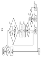
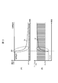
- TCU It is a circuit diagram of TCU in this Embodiment. It is a flowchart which shows a drive control process. It is a figure which shows the relationship between the monitoring current with respect to time, and a duty ratio.
- FIG. 1 shows a schematic configuration of the control device 1.
- the control device 1 is, for example, a TCU (Transmission Control Unit) that controls the operation of the transmission.
- TCU Transmission Control Unit
- Control device 1 inputs electric power from battery 35 mounted on the vehicle from input terminal 31.
- the input electric power is input to, for example, six drive circuits 24 via reverse protection 33 and CHSS (Common High Side Switch) 34.
- CHSS Common High Side Switch
- one drive circuit 24 is shown as an example.
- the electric power input into the drive circuit 24 is switched ON / OFF based on a control signal from the control unit 200 and is output from the output terminal 32 to the load SOL.
- the drive circuit 24 controls the transmission as a control target in accordance with the operation of a load SOL such as a solenoid that is a part of the shift actuator 56 described above.
- This solenoid is, for example, an actuator for driving a hydraulic valve of a vehicle transmission.
- IHSS Intelligent High Side Switch
- the current control switch 24A is connected to the control unit 200.
- the control unit 200 controls the current amount of the load current I to be supplied to the load SOL by performing on / off control on the current control switch 24A while changing the duty ratio of each pulse width in the pulse width control, for example. To do.
- the current detector 24B is provided between the load SOL and the current control switch 24A.
- the current detection unit 24B includes a shunt resistor 24D, and detects a load current I supplied from the battery 35 to the load SOL by measuring a current (corresponding to a load current I described later) flowing through the shunt resistor 24D. .
- the amount of the load current I is fed back to the control unit 200 as a detection current IN1.
- the control unit 200 adjusts the current amount of the load current supplied to the load SOL by controlling the duty ratio of the current control switch 24A based on the current amount of the load current detected by the current detection unit 24B. It is determined whether or not an abnormality has occurred according to the amount of load current I detected by the unit 24B.
- resistors R1, R2, and R3 are provided in series between a power source having a power supply voltage of 5 V and the ground, and a coupling portion between the resistors R2 and R3 is a control unit 200. It is connected to the.
- a voltage (corresponding to a “specific voltage” to be described later) at the coupling point of the resistors R2 and R3 is fed back to the control unit 200 by the voltage dividing ratio of the resistors R1, R2, and R3.
- the value of the voltage fed back in this way is also called a detection voltage IN2. That is, the value of the detection voltage at the connection point between the resistor R2 and the resistor R3 is fed back to the control unit 200 as the detection voltage IN2.
- FIG. 2 shows an example of drive control processing.
- the control unit 200 initializes each bit BIT0 to BIT5 as an initial state.
- the controller 200 determines whether or not the load current I as the detection current IN1 fed back from the current control switch 24A exceeds 1.8A (step S101).
- step S103 the control unit 200 indicates that the drive current flowing through the drive circuit 24, that is, the current amount of the load current I detected by the current detection unit 24B is smaller than a predetermined value, and the duty ratio is larger than the predetermined value.
- the first condition or the drive current flowing through the drive circuit 24, that is, the load current I detected by the current detection unit 24B is larger than a predetermined decrease rate, and the duty ratio is larger than a predetermined increase rate.
- the second condition is established, the disconnection in the load SOL (open load OP) and the short circuit in the battery 35 (short battery SB) are distinguished from each other based on the specific voltage fed back as the detection voltage IN2. .
- control unit 200 detects that the detection current IN1 detected by the current detection unit 24B is less than 41 mA and the duty ratio exceeds 23.2% (first condition), or the current detection unit It is determined whether or not the detection current IN1 by 24B is larger than a predetermined decrease rate and the duty ratio exceeds a predetermined increase rate (second condition) (step S103).
- the control unit 200 uses a current control switch (IHSS) 24A that is a current switch circuit portion for controlling the solenoid drive, and the load current flowing through the shunt resistor 24D and the load current flowing through the load SOL is equal to or less than a predetermined threshold value close to zero. It is constantly monitored whether or not the first condition that the value of the duty ratio based on the drive instruction is larger than a predetermined value is satisfied. When the first condition or the second condition is satisfied, the control unit 200 does not sufficiently flow the load current even though the drive instruction to the load SOL is given to a certain degree. It is determined that there is a possibility of abnormality, that is, there is a possibility of short battery SB or open load OP.
- IHSS current control switch
- control unit 200 turns off the current control switch 24A (step S106). Further, as a detailed confirmation method of the abnormality content, for example, the control unit 200 measures the potential upstream of the shunt resistor 24D in a state where the current control switch 24A is once turned off, and performs a detailed determination. Specifically, the control unit 200 determines whether or not the detected voltage IN2 is less than 2.13 V, for example (step S107).
- the control unit 200 determines that there is no abnormality (normal state) (step S108). On the other hand, when the detected voltage IN2 is not less than 2.13V and less than 2.13V, the control unit 200 executes Step S109.
- step S109 the control unit 200 determines whether or not the detection voltage IN2 is 2.13V or more and less than 3.98V (hereinafter referred to as “third condition”).
- control unit 200 distinguishes between disconnection in the load SOL (open load OP) and short circuit in the battery 35 (short battery SB) based on the detection voltage IN2.
- the load current I exceeding the set current threshold value is applied to the shunt resistor 24D depending on the magnitude of the values of the minute resistance and the shunt resistor 24D. At first glance, there is a possibility that no abnormality is detected.
- the threshold value for detecting a state in which there is a possibility of abnormality is a combination of the current threshold value and the duty ratio threshold value
- the range that can be detected on the two-dimensional plane of the current to duty ratio is the vertex. Is a rectangular area on a sloping straight line at the lower limit of the operating range of the load SOL.
- the duty ratio threshold is increased accordingly. Will go up. As a result, it seems that an abnormality cannot be detected in a low current and low duty ratio region.
- each abnormality including a short circuit of the battery 35 and a disconnection in the load can be distinguished from each other and detected more reliably.
- 3 (A) and 3 (B) show states such as current that the control unit 200 can detect the short battery SB, respectively.
- the short battery SB indicates that a short battery has occurred at the time shown.
- the control unit 200 is triggered by the occurrence of the short battery SB, and the detected current detected by the current detection unit 24B, that is, the second condition described above.
- IN1 (corresponding to the monitoring current Im shown in the figure) is larger than the predetermined drop rate (corresponding to the elliptical portion of the broken line shown in FIG. 3A), and the duty ratio Dr is a predetermined high threshold ratio (in the case shown) 23.2%) (corresponding to the dashed oval portion shown in FIG. 3B) is determined.
- control unit 200 determines whether or not the output terminal 32 and the input terminal 31 are short-circuited based on the first condition described above and the second condition described above, that is, a short battery. It is possible to detect whether SB has occurred.
- Control device 24A ... Current control switch, 24B ... Current detection unit, 200 ... Control unit
Landscapes
- Engineering & Computer Science (AREA)
- Power Engineering (AREA)
- Mechanical Engineering (AREA)
- Testing Of Short-Circuits, Discontinuities, Leakage, Or Incorrect Line Connections (AREA)
- Measurement Of Current Or Voltage (AREA)
- Protection Of Static Devices (AREA)
- Emergency Protection Circuit Devices (AREA)
Abstract
バッテリの短絡及び負荷における断線を含む各異常を互いに区別して確実に検出できる制御装置を提案する。 入力端子から入力された駆動電流のON/OFFを切り替えて出力端子から出力することにより該出力端子に接続されている駆動対象の動作を制御する電子制御装置において、駆動電流のON/OFFを切り替えて出力する駆動回路と、駆動回路の動作を制御する制御部とを備え、制御部は、駆動回路を流れる駆動電流が所定値よりも小さく、かつ、駆動回路に指示するデューティ比が所定値よりも大きい第1の条件と、駆動回路を流れる駆動電流が所定の下降率よりも大きく、かつ、駆動回路に指示するデューティ比が所定の上昇率よりも大きい第2の条件とに基づいて、出力端子と入力端子との間が短絡しているか否かを検出する。
Description
本発明は、電子制御装置に関し、特に駆動に大電流を必要とする負荷のための電子制御装置に適用して好適なものである。
従来車両には、直流のバッテリ電圧で駆動されて動作が制御されるトランスミッション油圧制御用のアクチュエータとしてソレノイドバルブが設けられている。ソレノイドバルブを駆動する駆動回路は、例えばTCU(Transmission Control Unit)内に設けられる。このような駆動回路においては、ソレノイドバルブの高電圧側が電流スイッチ回路部分及び実電流値検出部分に接続されている。一方でソレノイドバルブの下流側が直接アースに接続されている。
この駆動回路においては、ソレノイドバルブへ接続されるべき端子(以下「ソレノイド端子」と呼ぶ)とバッテリ電圧との間の接続線の短絡(以下「ショートバッテリ」と呼ぶ)またはソレノイド端子における断線(以下「オープンロード」と呼ぶ)のような異常が仮に発生した場合各々の異常を確実に検出することが求められる。
上述したようにショートバッテリやオープンロードのような各異常を区別して確実に検出することが望まれているものの、現実的には両者を正確に区別しつつ確実に検出することは困難である。
本発明は以上の点を考慮してなされたもので、ショートバッテリを確実に検出することができる電子制御装置を提案するものである。
かかる課題を解決するため、本発明においては、入力端子から入力された駆動電流のON/OFFを切り替えて出力端子から出力することにより該出力端子に接続されている駆動対象の動作を制御する電子制御装置において、前記駆動電流のON/OFFを切り替えて出力する駆動回路と、前記駆動回路の動作を制御する制御部とを備え、前記制御部は、前記駆動回路を流れる駆動電流が所定値よりも小さく、かつ、前記駆動回路に指示するデューティ比が所定値よりも大きい第1の条件と、前記駆動回路を流れる駆動電流が所定の下降率よりも大きく、かつ、前記駆動回路に指示するデューティ比が所定の上昇率よりも大きい第2の条件とに基づいて、前記出力端子と、前記入力端子との間が短絡しているか否かを検出することを特徴とする。
本発明によれば、ショートバッテリを確実に検出することができる。
本発明の一実施の形態について図面を参照して説明する。なお以下の説明は、本発明を限定するものではなく、本発明の範囲内で適宜変更することができる。
図1は、制御装置1の概略構成を示す。この制御装置1は、例えばトランスミッションの動作を制御するTCU(Transmission Control Unit)である。
制御装置1は、車両に搭載されるバッテリ35からの電力を入力端子31から入力する。入力された電力は、リバースプロテクション33及びCHSS(Common High Side Switch)34を介して例えば6個の駆動回路24に入力される。図示の例では一例として1つの駆動回路24が表されている。駆動回路24内に入力された電力は、制御部200からの制御信号に基づいてON/OFFが切り替えられて、出力端子32から負荷SOLに対して出力される。
駆動回路24は上述したシフトアクチュエータ56の一部であるソレノイドのような負荷SOLの作動に応じて制御対象としてのトランスミッションを制御する。このソレノイドは例えば車両トランスミッションの油圧バルブを駆動するためのアクチュエータである。
駆動回路24内における左側には電流制御スイッチ(Individual High Side Switch(以下「IHSS」と呼ぶ))24A、電流検出部24B、シャント抵抗24D及びフライホイールダイオード24Eが設けられている。
電流制御スイッチ24Aは制御部200に接続されている。制御部200は、電流制御スイッチ24Aに対して、例えばパルス幅制御における各パルス幅のデューティ比を変更しながらオン/オフ制御を行うことにより負荷SOLに供給すべき負荷電流Iの電流量を制御する。
電流検出部24Bは負荷SOLと電流制御スイッチ24Aとの間に設けられている。この電流検出部24Bはシャント抵抗24Dを含んでおり、このシャント抵抗24Dに流れる電流(後述の負荷電流Iに相当)を計測することによりバッテリ35から負荷SOLに供給される負荷電流Iを検出する。この負荷電流Iの電流量は検出電流IN1として制御部200にフィードバックされる。
制御部200は電流検出部24Bによって検出される負荷電流の電流量に基づいて電流制御スイッチ24Aのデューティ比を制御することにより負荷SOLに供給される負荷電流の電流量を調整する一方、電流検出部24Bによって検出される負荷電流Iの電流量に応じて異常が発生しているか否かを判定する。
一方駆動回路24内における右側には、例えば5Vの電源電圧の電源とグランドとの間に抵抗R1,R2,R3が順に直列に設けられており抵抗R2と抵抗R3との結合部が制御部200に接続されている。制御部200には、抵抗R1,R2,R3の分圧比によって抵抗R2と抵抗R3との結合点における電圧(後述する「特定電圧」に相当)がフィードバックされる。このようにフィードバックされる電圧の値は検出電圧IN2とも呼ぶ。つまり制御部200には抵抗R2と抵抗R3との結合点における検出電圧の値が検出電圧IN2としてフィードバックされている。
図2は、駆動制御処理の一例を示す。制御部200は初期状態として各ビットBIT0~BIT5を各々初期化する。制御部200は電流制御スイッチ24Aからフィードバックされた検出電流IN1としての負荷電流Iが1.8Aを超えているか否かを判定する(ステップS101)。
制御部200は検出電流IN1としての負荷電流Iが1.8Aを超えている場合にはビットBIT0=1(過電流検出)に設定する(ステップS102)。すなわち制御部200はグランドへの短絡(ショードグランドに相当)が発生しているか否かを判定している。一方制御部200は検出電流IN1としての負荷電流Iが1.8Aを超えていない場合にテップS103を実行する。
ステップS103では制御部200が、駆動回路24を流れる駆動電流、すなわち電流検出部24Bによって検出される負荷電流Iの電流量が所定値よりも小さく、かつ、そのデューティ比が所定値よりも大きいという第1の条件、又は、上記駆動回路24を流れる駆動電流、すなわち電流検出部24Bによって検出される負荷電流Iが所定の下降率よりも大きく、かつ、上記デューティ比が所定の上昇率よりも大きいという第2の条件が成立している場合には、検出電圧IN2としてフィードバックされる特定電圧に基づいて負荷SOLにおける断線(オープンロードOP)とバッテリ35における短絡(ショートバッテリSB)とを各々区別する。
具体的には制御部200は電流検出部24Bによって検出される検出電流IN1が41mA未満でありかつそのデューティ比が23.2%を超えていること(第1の条件)、又は、電流検出部24Bによる検出電流IN1が所定の下降率より大きく、かつ、上記デューティ比が所定の上昇率を超えていること(第2の条件)が成立しているか否かを判定する(ステップS103)。
つまり制御部200はシャント抵抗24Dを流れるとともに負荷SOLを流れる負荷電流が0に近い所定の閾値以下であり、かつ、ソレノイド駆動制御のための電流スイッチ回路部分である電流制御スイッチ(IHSS)24Aによる駆動指示に基づくデューティ比の値が所定値よりも大きいという第1の条件が成立したか否かを常に監視している。制御部200は、このような第1の条件又は第2の条件が成立すると、負荷SOLに対する駆動指示はある程度の大きさでなされているのにも関わらず負荷電流が十分に流れていない、すなわち異常である可能性がある状態、つまり、ショートバッテリSBまたはオープンロードOPの可能性があると判定する。
制御部200は上述した第1の条件または第2の条件が成立していない場合には異常が発生していない状態(通常状態)であると判定する(ステップS108)。一方制御部200は上述した第1の条件または第2の条件が成立している場合ビットBIT5=1と設定する(ステップS105)。この状態は、ショートバッテリSB及びオープンロードOPのいずれかの状態を表している。
さらに制御部200は電流制御スイッチ24Aをオフとする(ステップS106)。さらに制御部200は異常内容の詳細な確認方法として、例えば電流制御スイッチ24Aを一旦オフにした状態でシャント抵抗24Dの上流の電位を測定して詳細な判断を実施する。具体的には制御部200は検出電圧IN2が例えば2.13V未満であるか否かを判定する(ステップS107)。
制御部200は検出電圧IN2が2.13V未満である場合には異常が発生していない状態(通常状態)であると判定する(ステップS108)。一方制御部200は検出電圧IN2が2.13V未満2.13V未満ではない場合にはステップS109を実行する。
ステップS109では制御部200によって検出電圧IN2が2.13V以上3.98V未満であるか否か(以下「第3の条件」という)が判定される。制御部200は検出電圧IN2が2.13V以上3.98V未満である場合にはビットBIT3=1と設定する(ステップS110)。このビットBIT3=1は上述したオープンロードOPの状態を示している。
一方制御部200は検出電圧IN2が2.13V以上3.98V未満ではない場合にはビットBIT2=1と設定する(ステップS111)。このビットBIT2=1は上述したショートバッテリSBの状態を示している。
以上のようにして制御部200は検出電圧IN2に基づいて負荷SOLにおける断線(オープンロードOP)とバッテリ35における短絡(ショートバッテリSB)とを各々区別する。
以上のように、上述した第1の条件が成立しただけで異常を判定しようとすると、微小抵抗及びシャント抵抗24Dの値の大小次第によっては設定した電流閾値以上の負荷電流Iがシャント抵抗24Dに流れてしまい、一見すると、異常が検知されないおそれも考えられる。
このように微小抵抗を介したショートバッテリSBの場合には従前の方法によって電流値の閾値を調整することによって異常検出について正確にカバーすることは困難である。なぜならば、負荷SOLの正常使用範囲は、電流-デューティ比の2次元平面上ではその下限が傾いた直線になる(傾きの幅は駆動電圧の変動幅や素子の抵抗値の温度変動幅に相当する)ため、異常の可能性が有る状態を検出するための閾値を、電流の閾値とデューティ比の閾値との組み合わせとすると、電流対ディーティ比の2次元平面上で検出可能な範囲は、頂点の1つが負荷SOLの使用範囲の下限の傾いた直線上にある長方形の領域になる。
上記のような微小抵抗を介したショートバッテリSBの場合をもこの方法で検出しようとして異常検出範囲が正常使用範囲と重ならないようにするために電流の閾値を上げるとそれに伴ってデューティ比の閾値が上がることとなる。その結果一見すると低電流かつ低ディーティ比領域において異常を検出できないようにも思える。
これに対し、本実施形態では、異常判定に関して上述した第2の条件も用いるためバッテリ35の短絡及び負荷における断線を含む各異常を互いに区別してより確実に検出することができるようになる。
図3(A)及び図3(B)は、それぞれ、制御部200がショートバッテリSBを検出しうる電流などの状態を示す。なお、図示の例では、ショートバッテリSBと図示した時点でショートバッテリが発生したことを表している。
制御部200は、図3(A)及び図3(B)に示すようにショートバッテリSBが発生したことを契機として、既述の第2の条件、すなわち電流検出部24Bによって検出される検出電流IN1(図示の監視電流Imに相当)が所定の下落率よりも大きく(図3(A)に示す破線の楕円部分に相当)、かつ、上記デューティ比Drが所定の高閾値比(図示の場合23.2%)を超えていること(図3(B)に示す破線の楕円部分に相当)が成立しているか否かを判定する。
このような判定の結果、制御部200が既述の第1の条件と上述した第2の条件とに基づいて出力端子32と入力端子31との間がショートしているか否か、すなわちショートバッテリSBが発生しているか否かを検出することができる。
1……制御装置、24A……電流制御スイッチ、24B……電流検出部、200……制御部
Claims (3)
- 入力端子(31)から入力された駆動電流のON/OFFを切り替えて出力端子(32)から出力することにより該出力端子(32)に接続されている駆動対象(56)の動作を制御する電子制御装置(1)において、
前記駆動電流のON/OFFを切り替えて出力する駆動回路(24)と、
前記駆動回路(24)の動作を制御する制御部(200)とを備え、
前記制御部(200)は、
前記駆動回路(24)を流れる駆動電流が所定値よりも小さく、かつ、前記駆動回路(24)に指示するデューティ比が所定値よりも大きい第1の条件と、前記駆動回路(24)を流れる駆動電流が所定の下降率よりも大きく、かつ、前記駆動回路(24)に指示するデューティ比が所定の上昇率よりも大きい第2の条件とに基づいて、前記出力端子(32)と、前記入力端子(31)との間が短絡(SB)しているか否かを検出する
ことを特徴とする電子制御装置。 - 前記駆動回路(24)に流れる駆動電流を計測する電流検出部(24B)と、
前記駆動回路(24)に流れる駆動電流を遮断可能な電流制御スイッチ(24A)とを備え、
前記制御部は、
前記第1の条件及び前記第2の条件を満たす場合、前記電流制御スイッッチをオフ状態として前記駆動回路(24)を流れる駆動電流を遮断した際に、前記電流制御スイッチ(24A)と前記電流検出部(24B)との接続点における特定電圧が所定電圧値未満である場合、通常状態であると判定する
請求項1に記載の電子制御装置。 - 前記制御部は、
前記第1の条件及び前記第2の条件を満たす場合、前記電流制御スイッッチをオフ状態として前記駆動回路(24)を流れる駆動電流を遮断した際に前記特定電圧が所定電圧値未満ではない場合、前記特定電圧が前記所定電圧値以上かつ他の所定電圧値よりも小さいときには、該出力端子(32)に接続されている駆動対象(56)が断線している(OP)と判定する
請求項2に記載の電子制御装置。
Priority Applications (1)
| Application Number | Priority Date | Filing Date | Title |
|---|---|---|---|
| JP2018538311A JP6781759B2 (ja) | 2016-09-12 | 2017-08-07 | 制御装置 |
Applications Claiming Priority (2)
| Application Number | Priority Date | Filing Date | Title |
|---|---|---|---|
| JP2016-177380 | 2016-09-12 | ||
| JP2016177380 | 2016-09-12 |
Publications (1)
| Publication Number | Publication Date |
|---|---|
| WO2018047553A1 true WO2018047553A1 (ja) | 2018-03-15 |
Family
ID=61562033
Family Applications (1)
| Application Number | Title | Priority Date | Filing Date |
|---|---|---|---|
| PCT/JP2017/028508 Ceased WO2018047553A1 (ja) | 2016-09-12 | 2017-08-07 | 制御装置 |
Country Status (2)
| Country | Link |
|---|---|
| JP (1) | JP6781759B2 (ja) |
| WO (1) | WO2018047553A1 (ja) |
Cited By (9)
| Publication number | Priority date | Publication date | Assignee | Title |
|---|---|---|---|---|
| CN110764024A (zh) * | 2018-07-10 | 2020-02-07 | 精工爱普生株式会社 | 振荡器、电子设备以及移动体 |
| JP2020182150A (ja) * | 2019-04-26 | 2020-11-05 | ボッシュ株式会社 | 電子制御装置及び異常検出方法 |
| JP2020182151A (ja) * | 2019-04-26 | 2020-11-05 | ボッシュ株式会社 | 電子制御装置及び異常検出方法 |
| JP2020182152A (ja) * | 2019-04-26 | 2020-11-05 | ボッシュ株式会社 | 電子制御装置及び異常検出方法 |
| JP2021072740A (ja) * | 2019-11-01 | 2021-05-06 | ローム株式会社 | スイッチ装置 |
| JP2022052288A (ja) * | 2020-09-23 | 2022-04-04 | 日立建機株式会社 | 電磁誘導負荷の制御装置 |
| JP2022064636A (ja) * | 2020-10-14 | 2022-04-26 | 株式会社デンソー | 磁気平衡式電流センサ |
| WO2022239446A1 (ja) * | 2021-05-11 | 2022-11-17 | ボッシュ株式会社 | パージバルブ駆動制御装置 |
| US12181946B2 (en) * | 2022-02-21 | 2024-12-31 | Rohm Co., Ltd. | Abnormality detection circuit, semiconductor device, electronic apparatus, and vehicle |
Citations (4)
| Publication number | Priority date | Publication date | Assignee | Title |
|---|---|---|---|---|
| JP2001045651A (ja) * | 1999-07-29 | 2001-02-16 | Taiheiyo Seiko Kk | レアショート判断装置及びレアショート判断方法 |
| JP2009089072A (ja) * | 2007-09-28 | 2009-04-23 | Hitachi Ltd | 電磁負荷装置の制御装置 |
| JP2013211711A (ja) * | 2012-03-30 | 2013-10-10 | Denso Corp | 誘導性負荷駆動装置 |
| JP2016141351A (ja) * | 2015-02-04 | 2016-08-08 | ボッシュ株式会社 | 電子制御装置のグランド断線検出方法及び電子制御装置 |
Family Cites Families (1)
| Publication number | Priority date | Publication date | Assignee | Title |
|---|---|---|---|---|
| JP2015145830A (ja) * | 2014-02-03 | 2015-08-13 | 株式会社デンソーウェーブ | フォトカプラの劣化判定装置 |
-
2017
- 2017-08-07 JP JP2018538311A patent/JP6781759B2/ja active Active
- 2017-08-07 WO PCT/JP2017/028508 patent/WO2018047553A1/ja not_active Ceased
Patent Citations (4)
| Publication number | Priority date | Publication date | Assignee | Title |
|---|---|---|---|---|
| JP2001045651A (ja) * | 1999-07-29 | 2001-02-16 | Taiheiyo Seiko Kk | レアショート判断装置及びレアショート判断方法 |
| JP2009089072A (ja) * | 2007-09-28 | 2009-04-23 | Hitachi Ltd | 電磁負荷装置の制御装置 |
| JP2013211711A (ja) * | 2012-03-30 | 2013-10-10 | Denso Corp | 誘導性負荷駆動装置 |
| JP2016141351A (ja) * | 2015-02-04 | 2016-08-08 | ボッシュ株式会社 | 電子制御装置のグランド断線検出方法及び電子制御装置 |
Cited By (19)
| Publication number | Priority date | Publication date | Assignee | Title |
|---|---|---|---|---|
| CN110764024B (zh) * | 2018-07-10 | 2023-06-23 | 精工爱普生株式会社 | 振荡器、电子设备以及移动体 |
| CN110764024A (zh) * | 2018-07-10 | 2020-02-07 | 精工爱普生株式会社 | 振荡器、电子设备以及移动体 |
| JP2020182150A (ja) * | 2019-04-26 | 2020-11-05 | ボッシュ株式会社 | 電子制御装置及び異常検出方法 |
| JP2020182151A (ja) * | 2019-04-26 | 2020-11-05 | ボッシュ株式会社 | 電子制御装置及び異常検出方法 |
| JP2020182152A (ja) * | 2019-04-26 | 2020-11-05 | ボッシュ株式会社 | 電子制御装置及び異常検出方法 |
| JP7313183B2 (ja) | 2019-04-26 | 2023-07-24 | ボッシュ株式会社 | 電子制御装置及び異常検出方法 |
| JP7313182B2 (ja) | 2019-04-26 | 2023-07-24 | ボッシュ株式会社 | 電子制御装置及び異常検出方法 |
| JP7313184B2 (ja) | 2019-04-26 | 2023-07-24 | ボッシュ株式会社 | 電子制御装置及び異常検出方法 |
| JP2021072740A (ja) * | 2019-11-01 | 2021-05-06 | ローム株式会社 | スイッチ装置 |
| JP7364429B2 (ja) | 2019-11-01 | 2023-10-18 | ローム株式会社 | スイッチ装置 |
| JP2022052288A (ja) * | 2020-09-23 | 2022-04-04 | 日立建機株式会社 | 電磁誘導負荷の制御装置 |
| JP7461259B2 (ja) | 2020-09-23 | 2024-04-03 | 日立建機株式会社 | 電磁誘導負荷の制御装置 |
| JP2022064636A (ja) * | 2020-10-14 | 2022-04-26 | 株式会社デンソー | 磁気平衡式電流センサ |
| JP7415867B2 (ja) | 2020-10-14 | 2024-01-17 | 株式会社デンソー | 磁気平衡式電流センサ |
| JPWO2022239446A1 (ja) * | 2021-05-11 | 2022-11-17 | ||
| WO2022239446A1 (ja) * | 2021-05-11 | 2022-11-17 | ボッシュ株式会社 | パージバルブ駆動制御装置 |
| JP7662772B2 (ja) | 2021-05-11 | 2025-04-15 | ボッシュ株式会社 | パージバルブ駆動制御装置 |
| US12322544B2 (en) | 2021-05-11 | 2025-06-03 | Bosch Corporation | Purge valve driving control device |
| US12181946B2 (en) * | 2022-02-21 | 2024-12-31 | Rohm Co., Ltd. | Abnormality detection circuit, semiconductor device, electronic apparatus, and vehicle |
Also Published As
| Publication number | Publication date |
|---|---|
| JP6781759B2 (ja) | 2020-11-04 |
| JPWO2018047553A1 (ja) | 2019-06-24 |
Similar Documents
| Publication | Publication Date | Title |
|---|---|---|
| JP6781759B2 (ja) | 制御装置 | |
| US7924538B2 (en) | Self-protecting crowbar | |
| CN105098723A (zh) | 电负载的供电控制装置 | |
| US7800875B2 (en) | Multi-level electronic protection system providing safe fault recovery for multiple digital control outputs | |
| WO2017179414A1 (ja) | リレー装置 | |
| JP6030849B2 (ja) | 半導体スイッチの制御装置 | |
| JP2023174919A (ja) | 車載用制御装置 | |
| KR20190106181A (ko) | 과전류 발생시 모터 구동 전원을 차단하는 eps 제어 장치 및 방법 | |
| JP7313183B2 (ja) | 電子制御装置及び異常検出方法 | |
| JP2020071047A (ja) | 熱感知回路の異常検出回路 | |
| EP2535995A2 (en) | Overcurrent limiting for high side solenoid switch controls | |
| EP1762001B1 (de) | Schaltungsanordnung und verfahren zur einstellung der leistungsaufnahme einer an einem gleichspannungsnetz betreibbaren last | |
| CN117724571B (zh) | 一种基于车载电源限流检测的功率控制系统 | |
| JP7313182B2 (ja) | 電子制御装置及び異常検出方法 | |
| JP7313184B2 (ja) | 電子制御装置及び異常検出方法 | |
| KR102252366B1 (ko) | 배터리 상태 감시 회로 및 배터리 장치 | |
| EP4113226B1 (en) | Current limiting circuit for i/o modules | |
| US11824528B2 (en) | Load drive device and control method of load drive device | |
| JP5033401B2 (ja) | ソレノイド駆動装置 | |
| US20250260318A1 (en) | Method and circuit for current control | |
| JP7042157B2 (ja) | 車両用アクチュエータの制御装置 | |
| JP5012724B2 (ja) | 電磁負荷の駆動装置 | |
| CN213817210U (zh) | 自诊断工业io模块 | |
| CN220895377U (zh) | 新能源车辆、智能接触器及其触点维护装置 | |
| JP7644502B2 (ja) | 直流遮断器 |
Legal Events
| Date | Code | Title | Description |
|---|---|---|---|
| 121 | Ep: the epo has been informed by wipo that ep was designated in this application |
Ref document number: 17848497 Country of ref document: EP Kind code of ref document: A1 |
|
| ENP | Entry into the national phase |
Ref document number: 2018538311 Country of ref document: JP Kind code of ref document: A |
|
| NENP | Non-entry into the national phase |
Ref country code: DE |
|
| 122 | Ep: pct application non-entry in european phase |
Ref document number: 17848497 Country of ref document: EP Kind code of ref document: A1 |