WO2018047496A1 - 車両の制動力制御装置 - Google Patents
車両の制動力制御装置 Download PDFInfo
- Publication number
- WO2018047496A1 WO2018047496A1 PCT/JP2017/026980 JP2017026980W WO2018047496A1 WO 2018047496 A1 WO2018047496 A1 WO 2018047496A1 JP 2017026980 W JP2017026980 W JP 2017026980W WO 2018047496 A1 WO2018047496 A1 WO 2018047496A1
- Authority
- WO
- WIPO (PCT)
- Prior art keywords
- braking force
- vehicle
- force control
- control device
- steering
- Prior art date
- Legal status (The legal status is an assumption and is not a legal conclusion. Google has not performed a legal analysis and makes no representation as to the accuracy of the status listed.)
- Ceased
Links
Images






Classifications
-
- B—PERFORMING OPERATIONS; TRANSPORTING
- B60—VEHICLES IN GENERAL
- B60T—VEHICLE BRAKE CONTROL SYSTEMS OR PARTS THEREOF; BRAKE CONTROL SYSTEMS OR PARTS THEREOF, IN GENERAL; ARRANGEMENT OF BRAKING ELEMENTS ON VEHICLES IN GENERAL; PORTABLE DEVICES FOR PREVENTING UNWANTED MOVEMENT OF VEHICLES; VEHICLE MODIFICATIONS TO FACILITATE COOLING OF BRAKES
- B60T8/00—Arrangements for adjusting wheel-braking force to meet varying vehicular or ground-surface conditions, e.g. limiting or varying distribution of braking force
- B60T8/17—Using electrical or electronic regulation means to control braking
- B60T8/174—Using electrical or electronic regulation means to control braking characterised by using special control logic, e.g. fuzzy logic, neural computing
-
- B—PERFORMING OPERATIONS; TRANSPORTING
- B60—VEHICLES IN GENERAL
- B60T—VEHICLE BRAKE CONTROL SYSTEMS OR PARTS THEREOF; BRAKE CONTROL SYSTEMS OR PARTS THEREOF, IN GENERAL; ARRANGEMENT OF BRAKING ELEMENTS ON VEHICLES IN GENERAL; PORTABLE DEVICES FOR PREVENTING UNWANTED MOVEMENT OF VEHICLES; VEHICLE MODIFICATIONS TO FACILITATE COOLING OF BRAKES
- B60T7/00—Brake-action initiating means
- B60T7/12—Brake-action initiating means for automatic initiation; for initiation not subject to will of driver or passenger
- B60T7/22—Brake-action initiating means for automatic initiation; for initiation not subject to will of driver or passenger initiated by contact of vehicle, e.g. bumper, with an external object, e.g. another vehicle, or by means of contactless obstacle detectors mounted on the vehicle
-
- B—PERFORMING OPERATIONS; TRANSPORTING
- B60—VEHICLES IN GENERAL
- B60T—VEHICLE BRAKE CONTROL SYSTEMS OR PARTS THEREOF; BRAKE CONTROL SYSTEMS OR PARTS THEREOF, IN GENERAL; ARRANGEMENT OF BRAKING ELEMENTS ON VEHICLES IN GENERAL; PORTABLE DEVICES FOR PREVENTING UNWANTED MOVEMENT OF VEHICLES; VEHICLE MODIFICATIONS TO FACILITATE COOLING OF BRAKES
- B60T8/00—Arrangements for adjusting wheel-braking force to meet varying vehicular or ground-surface conditions, e.g. limiting or varying distribution of braking force
- B60T8/17—Using electrical or electronic regulation means to control braking
- B60T8/1755—Brake regulation specially adapted to control the stability of the vehicle, e.g. taking into account yaw rate or transverse acceleration in a curve
-
- B—PERFORMING OPERATIONS; TRANSPORTING
- B60—VEHICLES IN GENERAL
- B60T—VEHICLE BRAKE CONTROL SYSTEMS OR PARTS THEREOF; BRAKE CONTROL SYSTEMS OR PARTS THEREOF, IN GENERAL; ARRANGEMENT OF BRAKING ELEMENTS ON VEHICLES IN GENERAL; PORTABLE DEVICES FOR PREVENTING UNWANTED MOVEMENT OF VEHICLES; VEHICLE MODIFICATIONS TO FACILITATE COOLING OF BRAKES
- B60T8/00—Arrangements for adjusting wheel-braking force to meet varying vehicular or ground-surface conditions, e.g. limiting or varying distribution of braking force
- B60T8/32—Arrangements for adjusting wheel-braking force to meet varying vehicular or ground-surface conditions, e.g. limiting or varying distribution of braking force responsive to a speed condition, e.g. acceleration or deceleration
- B60T8/321—Arrangements for adjusting wheel-braking force to meet varying vehicular or ground-surface conditions, e.g. limiting or varying distribution of braking force responsive to a speed condition, e.g. acceleration or deceleration deceleration
-
- B—PERFORMING OPERATIONS; TRANSPORTING
- B60—VEHICLES IN GENERAL
- B60W—CONJOINT CONTROL OF VEHICLE SUB-UNITS OF DIFFERENT TYPE OR DIFFERENT FUNCTION; CONTROL SYSTEMS SPECIALLY ADAPTED FOR HYBRID VEHICLES; ROAD VEHICLE DRIVE CONTROL SYSTEMS FOR PURPOSES NOT RELATED TO THE CONTROL OF A PARTICULAR SUB-UNIT
- B60W10/00—Conjoint control of vehicle sub-units of different type or different function
- B60W10/18—Conjoint control of vehicle sub-units of different type or different function including control of braking systems
-
- B—PERFORMING OPERATIONS; TRANSPORTING
- B60—VEHICLES IN GENERAL
- B60W—CONJOINT CONTROL OF VEHICLE SUB-UNITS OF DIFFERENT TYPE OR DIFFERENT FUNCTION; CONTROL SYSTEMS SPECIALLY ADAPTED FOR HYBRID VEHICLES; ROAD VEHICLE DRIVE CONTROL SYSTEMS FOR PURPOSES NOT RELATED TO THE CONTROL OF A PARTICULAR SUB-UNIT
- B60W10/00—Conjoint control of vehicle sub-units of different type or different function
- B60W10/20—Conjoint control of vehicle sub-units of different type or different function including control of steering systems
-
- B—PERFORMING OPERATIONS; TRANSPORTING
- B62—LAND VEHICLES FOR TRAVELLING OTHERWISE THAN ON RAILS
- B62D—MOTOR VEHICLES; TRAILERS
- B62D6/00—Arrangements for automatically controlling steering depending on driving conditions sensed and responded to, e.g. control circuits
-
- B—PERFORMING OPERATIONS; TRANSPORTING
- B60—VEHICLES IN GENERAL
- B60T—VEHICLE BRAKE CONTROL SYSTEMS OR PARTS THEREOF; BRAKE CONTROL SYSTEMS OR PARTS THEREOF, IN GENERAL; ARRANGEMENT OF BRAKING ELEMENTS ON VEHICLES IN GENERAL; PORTABLE DEVICES FOR PREVENTING UNWANTED MOVEMENT OF VEHICLES; VEHICLE MODIFICATIONS TO FACILITATE COOLING OF BRAKES
- B60T2220/00—Monitoring, detecting driver behaviour; Signalling thereof; Counteracting thereof
- B60T2220/03—Driver counter-steering; Avoidance of conflicts with ESP control
-
- B—PERFORMING OPERATIONS; TRANSPORTING
- B60—VEHICLES IN GENERAL
- B60T—VEHICLE BRAKE CONTROL SYSTEMS OR PARTS THEREOF; BRAKE CONTROL SYSTEMS OR PARTS THEREOF, IN GENERAL; ARRANGEMENT OF BRAKING ELEMENTS ON VEHICLES IN GENERAL; PORTABLE DEVICES FOR PREVENTING UNWANTED MOVEMENT OF VEHICLES; VEHICLE MODIFICATIONS TO FACILITATE COOLING OF BRAKES
- B60T2250/00—Monitoring, detecting, estimating vehicle conditions
- B60T2250/04—Vehicle reference speed; Vehicle body speed
-
- B—PERFORMING OPERATIONS; TRANSPORTING
- B60—VEHICLES IN GENERAL
- B60T—VEHICLE BRAKE CONTROL SYSTEMS OR PARTS THEREOF; BRAKE CONTROL SYSTEMS OR PARTS THEREOF, IN GENERAL; ARRANGEMENT OF BRAKING ELEMENTS ON VEHICLES IN GENERAL; PORTABLE DEVICES FOR PREVENTING UNWANTED MOVEMENT OF VEHICLES; VEHICLE MODIFICATIONS TO FACILITATE COOLING OF BRAKES
- B60T2270/00—Further aspects of brake control systems not otherwise provided for
- B60T2270/10—ABS control systems
-
- B—PERFORMING OPERATIONS; TRANSPORTING
- B60—VEHICLES IN GENERAL
- B60T—VEHICLE BRAKE CONTROL SYSTEMS OR PARTS THEREOF; BRAKE CONTROL SYSTEMS OR PARTS THEREOF, IN GENERAL; ARRANGEMENT OF BRAKING ELEMENTS ON VEHICLES IN GENERAL; PORTABLE DEVICES FOR PREVENTING UNWANTED MOVEMENT OF VEHICLES; VEHICLE MODIFICATIONS TO FACILITATE COOLING OF BRAKES
- B60T2270/00—Further aspects of brake control systems not otherwise provided for
- B60T2270/30—ESP control system
-
- B—PERFORMING OPERATIONS; TRANSPORTING
- B60—VEHICLES IN GENERAL
- B60W—CONJOINT CONTROL OF VEHICLE SUB-UNITS OF DIFFERENT TYPE OR DIFFERENT FUNCTION; CONTROL SYSTEMS SPECIALLY ADAPTED FOR HYBRID VEHICLES; ROAD VEHICLE DRIVE CONTROL SYSTEMS FOR PURPOSES NOT RELATED TO THE CONTROL OF A PARTICULAR SUB-UNIT
- B60W2510/00—Input parameters relating to a particular sub-units
- B60W2510/10—Change speed gearings
- B60W2510/109—Direction of power flow
-
- B—PERFORMING OPERATIONS; TRANSPORTING
- B60—VEHICLES IN GENERAL
- B60W—CONJOINT CONTROL OF VEHICLE SUB-UNITS OF DIFFERENT TYPE OR DIFFERENT FUNCTION; CONTROL SYSTEMS SPECIALLY ADAPTED FOR HYBRID VEHICLES; ROAD VEHICLE DRIVE CONTROL SYSTEMS FOR PURPOSES NOT RELATED TO THE CONTROL OF A PARTICULAR SUB-UNIT
- B60W2510/00—Input parameters relating to a particular sub-units
- B60W2510/20—Steering systems
-
- B—PERFORMING OPERATIONS; TRANSPORTING
- B60—VEHICLES IN GENERAL
- B60W—CONJOINT CONTROL OF VEHICLE SUB-UNITS OF DIFFERENT TYPE OR DIFFERENT FUNCTION; CONTROL SYSTEMS SPECIALLY ADAPTED FOR HYBRID VEHICLES; ROAD VEHICLE DRIVE CONTROL SYSTEMS FOR PURPOSES NOT RELATED TO THE CONTROL OF A PARTICULAR SUB-UNIT
- B60W2520/00—Input parameters relating to overall vehicle dynamics
- B60W2520/12—Lateral speed
-
- B—PERFORMING OPERATIONS; TRANSPORTING
- B60—VEHICLES IN GENERAL
- B60W—CONJOINT CONTROL OF VEHICLE SUB-UNITS OF DIFFERENT TYPE OR DIFFERENT FUNCTION; CONTROL SYSTEMS SPECIALLY ADAPTED FOR HYBRID VEHICLES; ROAD VEHICLE DRIVE CONTROL SYSTEMS FOR PURPOSES NOT RELATED TO THE CONTROL OF A PARTICULAR SUB-UNIT
- B60W2520/00—Input parameters relating to overall vehicle dynamics
- B60W2520/26—Wheel slip
-
- B—PERFORMING OPERATIONS; TRANSPORTING
- B60—VEHICLES IN GENERAL
- B60W—CONJOINT CONTROL OF VEHICLE SUB-UNITS OF DIFFERENT TYPE OR DIFFERENT FUNCTION; CONTROL SYSTEMS SPECIALLY ADAPTED FOR HYBRID VEHICLES; ROAD VEHICLE DRIVE CONTROL SYSTEMS FOR PURPOSES NOT RELATED TO THE CONTROL OF A PARTICULAR SUB-UNIT
- B60W2530/00—Input parameters relating to vehicle conditions or values, not covered by groups B60W2510/00 or B60W2520/00
-
- B—PERFORMING OPERATIONS; TRANSPORTING
- B60—VEHICLES IN GENERAL
- B60W—CONJOINT CONTROL OF VEHICLE SUB-UNITS OF DIFFERENT TYPE OR DIFFERENT FUNCTION; CONTROL SYSTEMS SPECIALLY ADAPTED FOR HYBRID VEHICLES; ROAD VEHICLE DRIVE CONTROL SYSTEMS FOR PURPOSES NOT RELATED TO THE CONTROL OF A PARTICULAR SUB-UNIT
- B60W2710/00—Output or target parameters relating to a particular sub-units
- B60W2710/18—Braking system
-
- B—PERFORMING OPERATIONS; TRANSPORTING
- B60—VEHICLES IN GENERAL
- B60W—CONJOINT CONTROL OF VEHICLE SUB-UNITS OF DIFFERENT TYPE OR DIFFERENT FUNCTION; CONTROL SYSTEMS SPECIALLY ADAPTED FOR HYBRID VEHICLES; ROAD VEHICLE DRIVE CONTROL SYSTEMS FOR PURPOSES NOT RELATED TO THE CONTROL OF A PARTICULAR SUB-UNIT
- B60W2710/00—Output or target parameters relating to a particular sub-units
- B60W2710/20—Steering systems
-
- B—PERFORMING OPERATIONS; TRANSPORTING
- B60—VEHICLES IN GENERAL
- B60W—CONJOINT CONTROL OF VEHICLE SUB-UNITS OF DIFFERENT TYPE OR DIFFERENT FUNCTION; CONTROL SYSTEMS SPECIALLY ADAPTED FOR HYBRID VEHICLES; ROAD VEHICLE DRIVE CONTROL SYSTEMS FOR PURPOSES NOT RELATED TO THE CONTROL OF A PARTICULAR SUB-UNIT
- B60W30/00—Purposes of road vehicle drive control systems not related to the control of a particular sub-unit, e.g. of systems using conjoint control of vehicle sub-units
- B60W30/06—Automatic manoeuvring for parking
-
- B—PERFORMING OPERATIONS; TRANSPORTING
- B60—VEHICLES IN GENERAL
- B60W—CONJOINT CONTROL OF VEHICLE SUB-UNITS OF DIFFERENT TYPE OR DIFFERENT FUNCTION; CONTROL SYSTEMS SPECIALLY ADAPTED FOR HYBRID VEHICLES; ROAD VEHICLE DRIVE CONTROL SYSTEMS FOR PURPOSES NOT RELATED TO THE CONTROL OF A PARTICULAR SUB-UNIT
- B60W30/00—Purposes of road vehicle drive control systems not related to the control of a particular sub-unit, e.g. of systems using conjoint control of vehicle sub-units
- B60W30/18—Propelling the vehicle
- B60W30/18009—Propelling the vehicle related to particular drive situations
- B60W30/18054—Propelling the vehicle related to particular drive situations at stand still, e.g. engine in idling state
-
- B—PERFORMING OPERATIONS; TRANSPORTING
- B62—LAND VEHICLES FOR TRAVELLING OTHERWISE THAN ON RAILS
- B62D—MOTOR VEHICLES; TRAILERS
- B62D15/00—Steering not otherwise provided for
- B62D15/02—Steering position indicators ; Steering position determination; Steering aids
- B62D15/025—Active steering aids, e.g. helping the driver by actively influencing the steering system after environment evaluation
-
- B—PERFORMING OPERATIONS; TRANSPORTING
- B62—LAND VEHICLES FOR TRAVELLING OTHERWISE THAN ON RAILS
- B62D—MOTOR VEHICLES; TRAILERS
- B62D15/00—Steering not otherwise provided for
- B62D15/02—Steering position indicators ; Steering position determination; Steering aids
- B62D15/027—Parking aids, e.g. instruction means
- B62D15/0285—Parking performed automatically
-
- B—PERFORMING OPERATIONS; TRANSPORTING
- B62—LAND VEHICLES FOR TRAVELLING OTHERWISE THAN ON RAILS
- B62D—MOTOR VEHICLES; TRAILERS
- B62D6/00—Arrangements for automatically controlling steering depending on driving conditions sensed and responded to, e.g. control circuits
- B62D6/001—Arrangements for automatically controlling steering depending on driving conditions sensed and responded to, e.g. control circuits the torque NOT being among the input parameters
Definitions
- the present invention relates to a braking force control device that individually controls the braking force of steered wheels and non-steered wheels when the vehicle is decelerated.
- the driving operation that is steered by a stopped vehicle is called stationary, and is a driving operation that enables the vehicle to turn at the minimum turning radius of the vehicle. Further, the turning radius during turning can be made constant by performing a stationary operation. Since a stationary operation may be necessary when the vehicle turns in a narrow space and the traveling track of the vehicle can be simplified, the stationary operation is conventionally performed by many drivers. Similarly, in an autopilot system, the stationary operation is still an important driving operation because of the need for a small space and the simplification of the steering algorithm.
- the steered wheel In steering in a stopped state, the steered wheel rotates about the kingpin axis by the steering angle, but if there is a distance between the kingpin axis and the center of the tire ground contact surface of the steered wheel, the so-called scrub radius, there is a tire contact.
- the total drag amount of the tire is larger when the tire is rotated about the kingpin axis than the tire is rotated about the center of the ground.
- the scrub radius is determined by the positional relationship between the kingpin shaft and the wheel. In general, the smaller the scrub radius, the smaller the steering force during steering, and the smaller the force that the steering device receives from the ground. Therefore, the kingpin shaft may be designed to be as close to the wheel center as possible. In many cases, the scrub radius cannot be designed to be small due to various restrictions such as a suspension device, a steering device, and a driving force transmission device.
- Patent Documents 1 to 3 disclose methods for releasing the braking of the steered wheels at the time of stationary.
- Patent Document 1 discloses a method of loosening the braking force of a steered wheel when a steering operation is detected while the vehicle is stopped.
- Patent Document 2 discloses a method for recovering the braking force by detecting the intention of the occupant or the start of movement of the vehicle after relaxing the braking force of the steered wheels, as in Patent Document 1.
- Patent Document 3 discloses a method in which the same control as that of Patent Document 1 or 2 for reducing the braking force of the steering wheel is not performed when a road surface gradient is detected.
- the control for reducing the braking force is performed after detecting the stationary operation.
- the amount of steering between the delay until the control start for the detection margin and the control delay time due to the delay for the required time of braking force relaxation control after the start of control does not act on.
- the steering speed is high
- the steering amount during the control delay time increases.
- the detection margin is necessary to prevent erroneous detection of the control, and there is a performance limit of the apparatus in the time required for the braking force relaxation control.
- the present invention has been made in view of the above problems, and an object of the present invention is to reduce a steering load at the time of stationary, reduce a burden on a steering device, and suppress stress accumulation due to stationary, and a tire and a suspension. It is an object of the present invention to provide a braking force control device capable of preventing the generation of abnormal noise and vehicle swing when the braking force of a steering wheel is reduced while reducing the burden on the device and the steering device.
- the present invention provides a stop braking force control unit that individually controls the braking force of the steered wheel and the non-steered wheel when the vehicle is decelerated, and a pre-detection of steering in the stopped state of the vehicle.
- a stop unit, and the stop braking force control unit determines a braking force of the steered wheel based on a braking force during normal braking when the advance detection unit detects in advance the steering in a stopped state of the vehicle. It is assumed that the braking force relaxation control is also performed to reduce the braking force.
- the present invention configured as described above, it is detected in advance that steering (stationary) is performed in a state in which the vehicle is stopped, and the braking force of the steered wheels is adjusted during normal braking before the stationary is started.
- braking force relaxation control that lowers the braking force
- the tire, suspension device, and steering device are reduced by reducing the steering load at the time of off-loading, reducing the burden on the steering device, and suppressing stress accumulation due to the off-roading. Can be reduced. Further, by suppressing the accumulation of stress in the tire, the suspension device, and the steering device, it is possible to prevent the generation of abnormal noise and vehicle swing when the braking force of the steered wheels is relaxed.
- the present invention it is possible to reduce the steering load at the time of downshifting, to reduce the burden on the steering device, and to reduce the stress accumulation due to the offending, thereby reducing the burden on the tire, the suspension device, and the steering device.
- When relaxing the braking force it is possible to prevent abnormal noise and vehicle swinging.
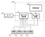
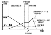
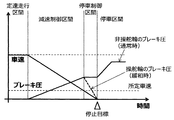
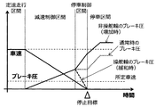
- FIG. 1 is an overall configuration diagram illustrating an example of a braking force control system including a braking force control device according to a first embodiment of the present invention. It is a control block diagram which shows the control structure of the braking force control apparatus which concerns on 1st Example of this invention. It is a flowchart which shows the braking force relaxation control in 1st Example of this invention. It is a time chart which shows an example of the change of the vehicle speed and brake pressure at the time of performing the braking force relaxation control at the time of a stop in the 1st Example of this invention. It is a time chart which shows the other example of the change of the vehicle speed and brake pressure at the time of performing the braking force relaxation control at the time of a stop in the 1st Example of this invention.
- braking force control apparatus when it is determined that there is no problem even if the stationary detection is detected in advance based on the state of the vehicle and the braking force of the steering wheel is reduced from that during normal braking. Control (hereinafter referred to as “braking force relaxation control” as appropriate).
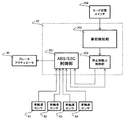
- FIG. 1 is an overall configuration diagram showing an example of a braking force control system including a braking force control device according to a first embodiment of the present invention.
- the braking force control system includes a master cylinder 10 and an ABS / ESC ECU (braking force control device that individually controls the braking force of the steering wheels 51 and 52 and the non-steering wheels 53 and 54 when the vehicle is decelerated.
- An electronic control unit) 20, a brake actuator 30, a steering assist device 40, and wheel speed sensors 61 to 64 are provided as main components.
- the master cylinder 10 can generate a master cylinder pressure when an occupant operates a brake pedal (not shown).
- the braking force control device 20 controls the brake actuator 30 and adjusts the braking pressure (braking pressure) of each wheel 51 to 54 of the vehicle based on the master cylinder pressure, thereby individually adjusting the braking force of each wheel 51 to 54. Can be adjusted to.
- the brake actuator 30 can increase or decrease the brake pressure of each of the wheels 51 to 54 even when the master cylinder pressure is not generated.
- the wheel speed sensors 61 to 64 can generate signal waveforms corresponding to the rotational speeds of the wheels 51 to 54, and the braking force control device 20 can determine the vehicle speed of the vehicle based on the signal waveforms generated by the wheel speed sensors 61 to 64. Can be measured.
- the steering assist device 40 can assist the steering force due to the occupant's steering intention.
- FIG. 2 is a control block diagram showing a control configuration of the braking force control device 20.
- the braking force control device 20 includes an ABS / ESC control unit 201, a stop braking force control unit 202, and a prior detection unit 203 as basic components, and inputs from wheel speed sensors 61 to 64 and the like.
- the brake actuator 30 is controlled based on the received signal.
- the ABS / ESC control unit 201 is a control block mounted in the braking force control device 20 and controls the brake actuator 30.
- the ABS / ESC control unit 201 receives signals from the wheel speed sensors 61 to 64 and generates a vehicle speed signal.
- the prior detection unit 203 inputs information on each part of the vehicle according to the prior detection method, and controls the stop braking force control unit 202 based on the detection result.
- the prior detection unit 203 may be mounted in the braking force control device 20 or may be mounted in another controller device.
- the stop braking force control unit 202 controls the ABS / ESC control unit 201 based on the signal from the prior detection unit 203 and the vehicle speed signal from the ABS / ESC control unit 201.
- the stop braking force control unit 202 may be mounted in the braking force control device 20 or may be mounted in another controller device.
- the input from the stop braking force control unit 202 to the ABS / ESC control unit 201 is, for example, a signal designating the brake pressure upper limit value of each of the wheels 51 to 54, and a low value as the brake pressure upper limit value of the steered wheels 51 and 52.
- the braking force of the steered wheels 51 and 52 can be relaxed.
- this input is, for example, a signal designating a brake pressure increasing / decreasing value of each of the wheels 51 to 54, by specifying decreasing pressure for the steering wheels 51, 52 and increasing pressure for the non-steering wheels 53, 54, The braking force of the entire vehicle can also be maintained. This is effective, for example, when the braking force of the steered wheels 51 and 52 is eased on a gradient road.
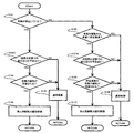
- FIG. 3 is a flowchart showing the braking force relaxation control in this embodiment.
- the control shown in this flowchart is always executed by the stop braking force control unit 202.
- each step constituting this flowchart will be described in order.
- step S101 it is determined whether or not the vehicle is stopped based on the vehicle speed signal measured by the wheel speed sensor sensors 61 to 64 (step S101).
- step S101 If it is determined in step S101 that the vehicle is stopped (YES), it is determined whether or not a pre-detection in the current stop state is detected in advance by the prior detection unit 203 (step S102).
- the pre-detection unit 203 pre-detects a stationary stop when the state of the vehicle satisfies a pre-defined condition. Note that there may be a plurality of preconditions defined in advance, and these may be combined with an AND condition or an OR condition.
- step S102 If it is determined in step S102 that the stationary stop in the current stop state has not been detected in advance (NO), normal control is executed (step S103), and the process returns to step S101.
- the normal control is control for adjusting the brake pressure of each of the wheels 51 to 54 in accordance with the operation of the brake pedal by the occupant.
- step S104 it is determined whether or not the braking force relaxation of the steered wheels 51 and 52 is allowed (step S104).
- whether or not the braking force relaxation of the steered wheels 51 and 52 is allowed is determined based on whether or not the state of the vehicle does not satisfy a predetermined prohibition condition. Note that there may be a plurality of prohibition conditions defined in advance, and these may be combined with an AND condition or an OR condition.
- step S104 If it is determined in step S104 that the braking force relaxation of the steered wheels 51 and 52 is not permitted (NO), normal control is executed (step S103), and the process returns to step S101. On the other hand, when it is determined that the braking force relaxation of the steered wheels 51 and 52 is permitted (YES), the braking force relaxation control at the time of stop is executed (step S105), and the process returns to step S101.
- step S106 If it is determined in step S101 that the vehicle is not stopped (NO), it is determined whether the vehicle is being braked and the vehicle speed is below a predetermined vehicle speed (step S106). When it is determined in step S106 that the vehicle is not being braked or the vehicle speed is equal to or higher than the predetermined vehicle speed (NO), normal control is performed (step S108), and the process returns to step S101. On the other hand, when it is determined that the vehicle is braking and the vehicle speed is lower than the predetermined vehicle speed (YES), it is determined whether or not the pre-detection in the next stop state is detected in advance by the prior detection unit 203 (step S107). ).
- the prior detection unit 203 detects in advance a stationary stop in the next stop state when the state of the vehicle satisfies a predetermined precondition.
- a predetermined precondition there may be a plurality of preconditions defined in advance, and these may be combined with an AND condition or an OR condition.
- step S107 If it is determined in step S107 that the next stationary stop is not detected in advance (NO), normal control is executed (step S108), and the process returns to step S101.
- step S108 it is determined whether or not the braking force of the steered wheels 51 and 52 is allowed to be relaxed immediately before the stop.
- Step S109 whether or not the braking force of the steered wheels 51 and 52 is allowed to be relaxed immediately before the stop is determined based on whether or not a predetermined prohibition condition is satisfied. Note that there may be a plurality of prohibition conditions defined in advance, and these may be combined with an AND condition or an OR condition.
- step S109 If it is determined in step S109 that the braking force of the steered wheels 51 and 52 is not allowed to be relaxed (NO) immediately before stopping, normal control is executed (step S108), and the process returns to step S101. On the other hand, if it is determined that the braking force of the steered wheels 51 and 52 is allowed to be relaxed immediately before the stop (YES), the pre-stop braking force relaxation control is executed (step S110), and the process returns to step S101.
- FIG. 4 is a time chart showing an example of changes in the vehicle speed and the brake pressure when the braking force relaxation control at stop (step S105 in FIG. 3) is executed.
- the stop is detected in advance before or after the vehicle is stopped, and the brake pressure of the steering wheels 51 and 52 is decreased from that during normal braking after the vehicle is stopped, thereby reducing the steering load during the stop. is doing.
- FIG. 5 is a time chart showing another example of changes in the vehicle speed and the brake pressure when the braking force relaxation control at stop (step S105 in FIG. 3) is executed.
- a stationary stop is detected in advance before or after the vehicle stops, and after the vehicle stops, the brake pressure of the steering wheels 51 and 52 is decreased from that during normal braking (indicated by a dotted line in the figure).
- the brake pressure of the non-steered wheels 53 and 54 is increased compared with that during normal braking. Thereby, it is possible to reduce the steering load at the time of stationary and to maintain the stop braking force of the entire vehicle.
- FIG. 6 is a time chart showing an example of changes in the vehicle speed and brake pressure when the pre-stop braking force relaxation control (step S110 in FIG. 3) is executed.
- the stop is detected in advance, and immediately after that, the brake pressure of the steered wheels 51 and 52 is reduced, and the steering load at the time of the stop is detected. Has been reduced.
- the brake pressure of the steered wheels 51 and 52 can be reduced to zero before the vehicle stops, and it is possible to perform stationary with the steering load reduced immediately after the vehicle stops.
- FIG. 7 is a time chart showing another example of changes in vehicle speed and brake pressure when the pre-stop braking force relaxation control (step S110 in FIG. 3) is executed.
- the stationary detection is detected in advance, and immediately after that, the brake pressure of the steered wheels 51, 52 is decreased and at the same time the non-steered wheels 53, 54 brake pressure is increased.
- the stationary operation with the steering load reduced immediately after the vehicle stops, and to maintain the deceleration braking force of the entire vehicle.
- FIG. 8 is a control block diagram illustrating an example of pre-defined preconditions for pre-detecting a stationary stop.
- a mode changeover switch 204 is provided in addition to the configuration of FIG.
- the mode switching signal output from the mode switching switch 204 is a signal for the occupant to indicate whether or not braking force relaxation control for reducing the steering load at the time of stationary is desired. It is a binary signal which shows the mode which desires relaxation control, or the mode which does not desire braking force relaxation control.
- the pre-detection unit 203 determines that one of pre-defined pre-conditions for pre-detecting stationary is satisfied.
- the mode in which the braking force relaxation control is desired is, for example, described in advance as a mode for reducing the steering load at the time of stationary for the user, so that convenience can be appealed.
- the mode switching signal is a signal for the occupant to indicate whether or not the braking force relaxation control for reducing the steering load at the time of stationary is prohibited, for example, and the mode for prohibiting the braking force relaxation control This is a binary signal indicating a mode in which braking force relaxation control is not prohibited.
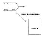
- FIG. 9 to FIG. 12 are diagrams showing examples of pre-defined preconditions for pre-detecting a stationary stop.
- the prior detection unit 203 determines that one of the preconditions for predetecting the stationary is satisfied. Whether the position of the vehicle has approached the parking position may be detected based on whether the distance between the position of the vehicle and the parking position is less than a predetermined distance using, for example, GPS or some communication means, You may detect based on whether the position of the vehicle entered into the predetermined area
- region for example, parking area
- the prior detection unit 203 assumes that one of the preliminary conditions for detecting the stationary stop is satisfied. judge. This is because, in forward / reverse switching, a direction change is often intended, and there is a high possibility that stationary will be performed immediately after forward / backward switching.
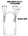
- the prior detection unit 203 detects the stationary in advance. It is determined that one of the preconditions is satisfied. This is because when the vehicle stops with the rudder angle attached, there is a high possibility that a stationary stop will be performed immediately before the next forward or backward movement, and when the vehicle stops at the parking position, the rudder angle is neutral. This is because there is a high possibility that deferrals will be made to return to
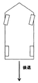
- the pre-detecting unit 203 determines that one of the pre-conditions for pre-detecting the stationary stop is satisfied. This is because there is a high possibility that the stationary operation will be performed at the stop after the retreat.
- FIGS. 13 to 17 are diagrams showing examples of pre-defined prohibition conditions for prohibiting the braking force relaxation control.
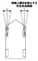
- the stop braking force control unit 202 prohibits the braking force relaxation control. It is determined that one of the predefined prohibition conditions for satisfying is satisfied. This is because when the steering angle of the steered wheels 51 and 52 at the time when the vehicle is stopped is close to neutral, the stop may be a stop at the parking position (or may not be at least a stop for turning). Due to the high price.
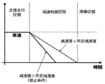
- the stop braking force control unit 202 has a predetermined prohibition condition for prohibiting the braking force relaxation control. Determine that one of them is satisfied. This is to prevent the braking force from becoming insufficient or braking from becoming unstable by relaxing the braking force of the steered wheels in the strong braking.
- the stop braking force control unit 202 determines that one of the predetermined prohibition conditions for prohibiting the braking force relaxation control is satisfied. . This is to prevent the braking force for deceleration of the vehicle and the braking force for maintaining the stop state of the vehicle from being insufficient by relaxing the braking force of the steered wheels 51 and 52. Whether or not the vehicle is located on a slope road is determined using, for example, an acceleration sensor or map information or based on a change in running resistance.
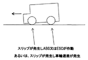
- the stop braking force control unit 202 determines that one of the predetermined prohibition conditions for prohibiting the braking force relaxation control is satisfied. This is to prevent the braking force for avoiding slipping from being insufficient by relaxing the braking force of the steered wheels 51 and 52. Note that whether or not the vehicle has slipped is determined based on, for example, whether or not ABS (anti-lock brake system) or ESC (side slip prevention device) is operated, or the wheel speed difference between the wheels 51 to 54.
- ABS anti-lock brake system
- ESC side slip prevention device
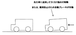
- the braking force of the steering wheels 51, 52 is not limited to a situation where the braking force of the steering wheels 51, 52 is greater than a predetermined braking force, or is not controlled by the occupant, but is controlled by the automatic steering system mounted on the vehicle.
- the stop braking force control unit 202 determines that one of the predetermined prohibition conditions for prohibiting the braking force relaxation control is satisfied. This is to prevent the braking force for avoiding the collision prevention from being insufficient by relaxing the braking force of the steered wheels 51 and 52.
- the present embodiment configured as described above, it is detected in advance that steering (stationary) is performed in a state where the vehicle is stopped, and the braking force of the steered wheels 51 and 52 is applied before the stationary is started.
- braking force relaxation control that lowers the braking force during normal braking
- the load on the steering system is reduced by reducing the steering load at the time of suspension, and the accumulation of stress due to the suspension is suppressed and the tire and suspension
- the burden on the device and the steering device can be reduced. Further, by suppressing the accumulation of stress in the tire, suspension device, and steering device, it is possible to prevent the generation of abnormal noise and vehicle swing when the braking force of the steered wheels 51, 52 is eased.
- the autopilot system not the occupant, steers the vehicle (including steering) and the occupant and the autopilot system share the steering of the vehicle.
- the autopilot system is, for example, a system that performs autopilot for the purpose of automatic parking, or a system that performs autopilot for the purpose of U-turn.
- Such an autopilot system plans some travel trajectory before the start of operation for the intended maneuver.
- a place where there is a possibility of performing a deferral is also planned in advance. Therefore, the braking force control apparatus according to the present embodiment reduces the braking force when it detects that there is no problem even if the stationary detection is detected in advance based on the steering plan and the braking force of the steering wheels 51 and 52 is reduced. Execute control.
- FIG. 18 is a control block diagram of the braking force control apparatus 20A according to the present embodiment. 18 is different from the control block diagram (shown in FIG. 2) in the first embodiment in that information from the steering planning unit 205 is input to the prior detection unit 203.
- the steering plan unit 205 creates a steering plan in accordance with input operations from various sensor devices and occupants, and inputs stationary information to the prior detection unit 203 before performing the stationary based on the steering plan.
- the prior detection unit 203 determines that stationary is scheduled in the current stop state or the next stop state.
- the steering planning unit 205, the prior detection unit 203, and the stop braking force control unit 202 may be mounted on the controller device for the automatic steering system, may be mounted in the braking force control device 20A, or other than that. You may mount in a controller apparatus.
- FIG. 19 is a flowchart showing the braking force relaxation control in this embodiment.
- the control shown in this flowchart is always executed by the stop braking force control unit 202 in the same manner as the control in the first embodiment (shown in FIG. 3).
- the difference from the first embodiment will be mainly described.
- the braking force relaxation control in this embodiment includes steps S102A and S107A instead of steps S102 and S107 in the first embodiment.
- step S101 If it is determined in step S101 that the vehicle is stopped, it is determined whether or not the prior detection unit 203 has previously detected a stationary stop in the current stop state (step S102A).
- the prior detection unit 203 detects the prior stop in the current stop state when the stop in the current stop state is scheduled in the operation plan.
- step S102A If it is determined in step S102A that the stationary stop in the current stop state is not scheduled (NO), normal control is executed (step S103), and the process returns to step S101. On the other hand, when it is determined in step S102A that the stationary stop in the current stop state is scheduled (YES), it is determined whether or not the braking force relaxation of the steered wheels 51 and 52 is allowed (step S104).
- step S106 If it is determined in step S106 that the vehicle is being braked and the vehicle speed is below the predetermined vehicle speed (YES), it is determined whether or not the next stop in the steering plan is scheduled in the operation plan (step S107A). ).
- step S107A If it is determined in step S107A that the next stoppage is not scheduled (NO), normal control is executed (step S108), and the process returns to step S101. On the other hand, if it is determined in step S107A that the next stoppage is scheduled (YES), whether or not the braking force of the steered wheels 51 and 52 is allowed to be relaxed immediately before the stop is determined. Determination is made (step S109).
- Example of this invention was explained in full detail, this invention is not limited to an above-described Example, Various modifications are included.
- the above-described embodiments have been described in detail for easy understanding of the present invention, and are not necessarily limited to those having all the configurations described. It is also possible to add a part of the configuration of another embodiment to the configuration of a certain embodiment, and delete a part of the configuration of a certain embodiment or replace it with a part of another embodiment. Is possible.
Landscapes
- Engineering & Computer Science (AREA)
- Transportation (AREA)
- Mechanical Engineering (AREA)
- Chemical & Material Sciences (AREA)
- Combustion & Propulsion (AREA)
- Physics & Mathematics (AREA)
- Fuzzy Systems (AREA)
- Mathematical Physics (AREA)
- Software Systems (AREA)
- Theoretical Computer Science (AREA)
- Regulating Braking Force (AREA)
Abstract
Description
これは、操舵輪51,52の制動力を緩和することでスリップを回避するための制動力が不足することを防止するためである。なお、車両がスリップしたか否かは、例えば、ABS(アンチロックブレーキシステム)又はESC(横滑り防止装置)が作動したか否かあるいは各車輪51~54の車輪速差に基づいて判定する。
Claims (22)
- 車両の減速時に操舵輪及び非操舵輪の制動力を個別に制御する停止制動力制御部と、
前記車両の停止状態での操舵を事前検知する事前検知部とを備え、
前記停止制動力制御部は、前記事前検知部により前記車両の停止状態での操舵が事前検知されたときに、前記操舵輪の制動力を通常制動時の制動力よりも低下させる制動力緩和制御を実行することを特徴とする車両の制動力制御装置。 - 請求項1に記載の車両の制動力制御装置において、
前記停止制動力制御部は、前記制動力緩和制御を実行すると同時に、前記非操舵輪の制動力を通常制動時の制動力よりも増加させることを特徴とする車両の制動力制御装置。 - 請求項1に記載の車両の制動力制御装置において、
前記事前検知部は、前記車両の制動中でかつ前記車両の速度が所定車速を下回ったときに、前記車両の停止状態での操舵が行われることを事前検知することを特徴とする車両の制動力制御装置。 - 請求項3に記載の車両の制動力制御装置において、
前記停止制動力制御部は、前記制動力緩和制御を実行すると同時に、前記車両の減速度が通常制動時の減速度と一致するように前記非操舵輪の制動力を増加させることを特徴とする車両の制動力制御装置。 - 請求項1に記載の車両の制動力制御装置において、
前記事前検知部は、前記車両の状態が予め規定した所定の事前条件を満たしているか否かに基づいて、前記車両の停止状態での操舵が行われることを事前検知することを特徴とする車両の制動力制御装置。 - 請求項5に記載の車両の制動力制御装置において、
前記所定の事前条件には、乗員により所定の意思表示操作が行われた場合が含まれることを特徴とする車両の制動力制御装置。 - 請求項5に記載の車両の制動力制御装置において、
前記所定の事前条件には、前記車両が駐車位置を含む所定領域内に進入した場合が含まれることを特徴とする車両の制動力制御装置。 - 請求項5に記載の車両の制動力制御装置において、
前記所定の事前条件には、乗員により前後進切替操作が行われた場合が含まれることを特徴とする車両の制動力制御装置。 - 請求項5に記載の車両の制動力制御装置において、
前記所定の事前条件には、前記車両が停止した時点の前記操舵輪の舵角が中立角度を含む所定角度範囲内に収まらない場合が含まれることを特徴とする車両の制動力制御装置。 - 請求項5に記載の車両の制動力制御装置において、
前記所定の事前条件には、前記車両が後退している場合が含まれることを特徴とする車両の制動力制御装置。 - 請求項1に記載の車両の制動力制御装置において、
前記停止制動力制御部は、前記車両の状態が予め規定した所定の禁止条件を満たしている場合に、前記制動力緩和制御を実行しないことを特徴とする車両の制動力制御装置。 - 請求項11に記載の車両の制動力制御装置において、
前記所定の禁止条件には、乗員により所定の意思表示操作が行われた場合が含まれることを特徴とする車両の制動力制御装置。 - 請求項11に記載の車両の制動力制御装置において、
前記所定の禁止条件には、前記車両が停止した時点の前記操舵輪の舵角が所定角度範囲内に収まる場合が含まれることを特徴とする車両の制動力制御装置。 - 請求項11に記載の車両の制動力制御装置において、
前記所定の禁止条件には、前記制動力緩和制御を実行することにより前記車両の制動力が不足する場合が含まれることを特徴とする車両の制動力制御装置。 - 請求項11に記載の車両の制動力制御装置において、
前記所定の禁止条件には、前記車両の制動中でかつ前記車両の減速度が所定減速度を上回っている場合が含まれることを特徴とする車両の制動力制御装置。 - 請求項11に記載の車両の制動力制御装置において、
前記所定の禁止条件には、前記車両が勾配路に位置する場合が含まれることを特徴とする車両の制動力制御装置。 - 請求項11に記載の車両の制動力制御装置において、
前記所定の禁止条件には、前記車両がスリップした場合が含まれることを特徴とする車両の制動力制御装置。 - 請求項17に記載の車両の制動力制御装置において、
前記車両がスリップしたか否かをアンチロックブレーキシステム又は横滑り防止装置が作動したか否かに基づいて判定することを特徴とする車両の制動力制御装置。 - 請求項17に記載の車両の制動力制御装置において、
前記車両がスリップしたか否かを前記操舵輪及び前記非操舵輪の車輪速差に基づいて判定することを特徴とする車両の制動力制御装置。 - 請求項11に記載の車両の制動力制御装置において、
前記所定の禁止条件には、前記操舵輪の制動力が所定制動力よりも大きい場合が含まれることを特徴とする車両の制動力制御装置。 - 請求項11に記載の車両の制動力制御装置において、
前記所定の禁止条件には、前記車両に搭載された自動操縦システムにより前記車両の衝突防止を目的として前記操舵輪の制動力が制御されている場合が含まれることを特徴とする車両の制動力制御装置。 - 請求項1に記載の車両の制動力制御装置において、
前記事前検知部は、操舵計画部で作成された操縦計画に基づいて前記車両の停止状態での操舵を事前検知することを特徴とする車両の制動力制御装置。
Priority Applications (3)
| Application Number | Priority Date | Filing Date | Title |
|---|---|---|---|
| DE112017002954.6T DE112017002954B4 (de) | 2016-09-06 | 2017-07-26 | Fahrzeugbremskraftsteuereinrichtung |
| JP2018538276A JP6647412B2 (ja) | 2016-09-06 | 2017-07-26 | 車両の制動力制御装置 |
| US16/317,002 US11472383B2 (en) | 2016-09-06 | 2017-07-26 | Vehicle braking force control device |
Applications Claiming Priority (2)
| Application Number | Priority Date | Filing Date | Title |
|---|---|---|---|
| JP2016173532 | 2016-09-06 | ||
| JP2016-173532 | 2016-09-06 |
Publications (1)
| Publication Number | Publication Date |
|---|---|
| WO2018047496A1 true WO2018047496A1 (ja) | 2018-03-15 |
Family
ID=61562733
Family Applications (1)
| Application Number | Title | Priority Date | Filing Date |
|---|---|---|---|
| PCT/JP2017/026980 Ceased WO2018047496A1 (ja) | 2016-09-06 | 2017-07-26 | 車両の制動力制御装置 |
Country Status (4)
| Country | Link |
|---|---|
| US (1) | US11472383B2 (ja) |
| JP (1) | JP6647412B2 (ja) |
| DE (1) | DE112017002954B4 (ja) |
| WO (1) | WO2018047496A1 (ja) |
Cited By (2)
| Publication number | Priority date | Publication date | Assignee | Title |
|---|---|---|---|---|
| CN114313004A (zh) * | 2022-01-05 | 2022-04-12 | 东风柳州汽车有限公司 | 自动泊车转向方法、装置、设备及存储介质 |
| US11760417B2 (en) | 2019-12-13 | 2023-09-19 | Honda Motor Co., Ltd. | Parking assist system and vehicle with automated parking capability |
Families Citing this family (6)
| Publication number | Priority date | Publication date | Assignee | Title |
|---|---|---|---|---|
| KR102466053B1 (ko) * | 2017-12-27 | 2022-11-14 | 현대자동차주식회사 | 자동 변속기 차량의 경사로 밀림 방지 방법 |
| KR102654528B1 (ko) * | 2018-12-07 | 2024-04-03 | 현대자동차주식회사 | 자동차용 선회 주행 제어 시스템 및 방법 |
| KR20200094868A (ko) * | 2019-01-30 | 2020-08-10 | 현대모비스 주식회사 | 차량의 주차 제어장치 및 그 방법 |
| CN112606702B (zh) * | 2020-11-30 | 2022-06-03 | 江铃汽车股份有限公司 | 一种能量回收控制方法、系统、存储介质及计算机设备 |
| CN117002484A (zh) * | 2023-07-12 | 2023-11-07 | 浙江吉利控股集团有限公司 | 一种泊车方法、系统、电子设备和存储介质 |
| US12344220B2 (en) | 2023-08-09 | 2025-07-01 | Robert Bosch Gmbh | Selective braking for steering loads |
Citations (2)
| Publication number | Priority date | Publication date | Assignee | Title |
|---|---|---|---|---|
| JP2014015082A (ja) * | 2012-07-06 | 2014-01-30 | Jtekt Corp | 制動制御装置 |
| JP2014168332A (ja) * | 2013-02-28 | 2014-09-11 | Hitachi Automotive Systems Ltd | モータ装置およびモータ駆動装置 |
Family Cites Families (15)
| Publication number | Priority date | Publication date | Assignee | Title |
|---|---|---|---|---|
| JPH07257336A (ja) * | 1994-03-24 | 1995-10-09 | Toyota Motor Corp | 制動力制御装置 |
| JP3570445B2 (ja) | 1995-08-21 | 2004-09-29 | フジモリ産業株式会社 | スパイラル管製造装置及びスパイラル管の製造方法 |
| JP3950729B2 (ja) * | 2002-04-23 | 2007-08-01 | アイシン精機株式会社 | 車両の運動制御装置 |
| JP2008094117A (ja) * | 2006-10-05 | 2008-04-24 | Toyota Motor Corp | 車両用制動力制御装置 |
| EP2106353B1 (en) * | 2007-01-25 | 2014-01-08 | Honda Motor Co., Ltd. | Vehicle systems control for improving stability |
| US8062175B2 (en) * | 2008-11-04 | 2011-11-22 | GM Global Technology Operations LLC | Method and apparatus for optimizing braking control during a threshold braking event |
| DE102009055059B4 (de) * | 2009-12-21 | 2023-02-02 | Robert Bosch Gmbh | Reduzieren des Lenkmoments bei Bremsmanövern |
| DE102010046472A1 (de) * | 2010-09-24 | 2012-03-29 | Gm Global Technology Operations Llc (N.D.Ges.D. Staates Delaware) | Fahrzeuglenksystem, Verfahren zum Betreiben eines Fahrzeuglenksystems, Einparkhilfe für ein Fahrzeug sowie Kraftfahrzeug |
| DE102010051203B4 (de) * | 2010-11-12 | 2022-07-28 | Zf Active Safety Gmbh | Verfahren zur Erkennung von kritischen Fahrsituationen von Lastkraft- oder Personenkraftwagen, insbesondere zur Vermeidung von Kollisionen |
| JP5589872B2 (ja) * | 2011-01-31 | 2014-09-17 | 株式会社アドヴィックス | 車両の運動制御装置 |
| JP5814866B2 (ja) * | 2012-06-26 | 2015-11-17 | 株式会社アドヴィックス | 車両用制動装置 |
| JP6204865B2 (ja) * | 2014-03-31 | 2017-09-27 | 日立オートモティブシステムズ株式会社 | 車両の運動制御システム、車両、および、プログラム |
| CN112146669B (zh) * | 2015-02-10 | 2024-08-27 | 御眼视觉技术有限公司 | 服务器系统、方法及机器可读介质 |
| DE102015202486A1 (de) * | 2015-02-12 | 2016-08-18 | Robert Bosch Gmbh | Verfahren und Vorrichtung zum Überwachen eines auf einem Parkplatz fahrenden Fahrzeugs |
| US9995232B2 (en) * | 2016-07-19 | 2018-06-12 | Ford Global Technologies, Llc | Method and system for operating an engine start-stop system in a vehicle |
-
2017
- 2017-07-26 DE DE112017002954.6T patent/DE112017002954B4/de active Active
- 2017-07-26 JP JP2018538276A patent/JP6647412B2/ja active Active
- 2017-07-26 US US16/317,002 patent/US11472383B2/en active Active
- 2017-07-26 WO PCT/JP2017/026980 patent/WO2018047496A1/ja not_active Ceased
Patent Citations (2)
| Publication number | Priority date | Publication date | Assignee | Title |
|---|---|---|---|---|
| JP2014015082A (ja) * | 2012-07-06 | 2014-01-30 | Jtekt Corp | 制動制御装置 |
| JP2014168332A (ja) * | 2013-02-28 | 2014-09-11 | Hitachi Automotive Systems Ltd | モータ装置およびモータ駆動装置 |
Cited By (2)
| Publication number | Priority date | Publication date | Assignee | Title |
|---|---|---|---|---|
| US11760417B2 (en) | 2019-12-13 | 2023-09-19 | Honda Motor Co., Ltd. | Parking assist system and vehicle with automated parking capability |
| CN114313004A (zh) * | 2022-01-05 | 2022-04-12 | 东风柳州汽车有限公司 | 自动泊车转向方法、装置、设备及存储介质 |
Also Published As
| Publication number | Publication date |
|---|---|
| DE112017002954B4 (de) | 2025-11-06 |
| US20190241163A1 (en) | 2019-08-08 |
| JP6647412B2 (ja) | 2020-02-14 |
| US11472383B2 (en) | 2022-10-18 |
| DE112017002954T5 (de) | 2019-03-07 |
| JPWO2018047496A1 (ja) | 2019-03-28 |
Similar Documents
| Publication | Publication Date | Title |
|---|---|---|
| JP6647412B2 (ja) | 車両の制動力制御装置 | |
| CN100545015C (zh) | 车辆制动控制装置 | |
| CN103204148B (zh) | 汽车列车的稳定方法和装置 | |
| US11260901B2 (en) | Selective braking of four wheel steering vehicle | |
| JP2002127886A (ja) | 車両の姿勢制御装置 | |
| JP7494739B2 (ja) | 車両制御装置 | |
| CN116133934B (zh) | 用于运行机动车的线控转向系统的方法以及控制装置、计算机程序和线控转向系统 | |
| JP2021014221A (ja) | 車両用外乱対処システム | |
| KR101997429B1 (ko) | 차량의 차선 유지 제어 방법 및 이를 구현하는 차선 유지 제어 장치 | |
| CN109689450A (zh) | 转向控制系统和用于控制转向的方法 | |
| KR20180052983A (ko) | Epb 장착 차량의 드리프트 로직 제어 방법 | |
| US8768592B2 (en) | Reducing the steering torque during braking maneuvers | |
| JP2021014220A (ja) | 車両用外乱対処システム | |
| CN108016494A (zh) | 区分驾驶员的有意的转向运动与驾驶员的矫正转向运动的方法 | |
| JP2008265722A (ja) | 走行支援装置および走行支援方法 | |
| KR20160087275A (ko) | 차량 자동 홀드 제어 방법 | |
| JP2011502858A (ja) | スーパーインポーズド・ステアリングの作動方法 | |
| KR20170064916A (ko) | 차량의 사륜 제어 방법 | |
| JP5333245B2 (ja) | 車両挙動制御装置 | |
| JP2005028995A (ja) | 車両の車速制御装置 | |
| JP5035538B2 (ja) | 操舵力制御装置 | |
| JP4742504B2 (ja) | 駆動制御装置 | |
| JP7757919B2 (ja) | 車両の制動制御システム | |
| JP5333801B2 (ja) | 操舵力制御装置 | |
| JP5333802B2 (ja) | 操舵力制御装置 |
Legal Events
| Date | Code | Title | Description |
|---|---|---|---|
| 121 | Ep: the epo has been informed by wipo that ep was designated in this application |
Ref document number: 17848441 Country of ref document: EP Kind code of ref document: A1 |
|
| ENP | Entry into the national phase |
Ref document number: 2018538276 Country of ref document: JP Kind code of ref document: A |
|
| WWE | Wipo information: entry into national phase |
Ref document number: 112017002954 Country of ref document: DE |
|
| 122 | Ep: pct application non-entry in european phase |
Ref document number: 17848441 Country of ref document: EP Kind code of ref document: A1 |
|
| WWG | Wipo information: grant in national office |
Ref document number: 112017002954 Country of ref document: DE |