WO2018047481A1 - 回転コネクタ - Google Patents
回転コネクタ Download PDFInfo
- Publication number
- WO2018047481A1 WO2018047481A1 PCT/JP2017/026508 JP2017026508W WO2018047481A1 WO 2018047481 A1 WO2018047481 A1 WO 2018047481A1 JP 2017026508 W JP2017026508 W JP 2017026508W WO 2018047481 A1 WO2018047481 A1 WO 2018047481A1
- Authority
- WO
- WIPO (PCT)
- Prior art keywords
- rotator
- gear
- stator
- rotation
- electrical connection
- Prior art date
- Legal status (The legal status is an assumption and is not a legal conclusion. Google has not performed a legal analysis and makes no representation as to the accuracy of the status listed.)
- Ceased
Links
Images




Classifications
-
- B—PERFORMING OPERATIONS; TRANSPORTING
- B60—VEHICLES IN GENERAL
- B60R—VEHICLES, VEHICLE FITTINGS, OR VEHICLE PARTS, NOT OTHERWISE PROVIDED FOR
- B60R16/00—Electric or fluid circuits specially adapted for vehicles and not otherwise provided for; Arrangement of elements of electric or fluid circuits specially adapted for vehicles and not otherwise provided for
- B60R16/02—Electric or fluid circuits specially adapted for vehicles and not otherwise provided for; Arrangement of elements of electric or fluid circuits specially adapted for vehicles and not otherwise provided for electric constitutive elements
- B60R16/023—Electric or fluid circuits specially adapted for vehicles and not otherwise provided for; Arrangement of elements of electric or fluid circuits specially adapted for vehicles and not otherwise provided for electric constitutive elements for transmission of signals between vehicle parts or subsystems
- B60R16/027—Electric or fluid circuits specially adapted for vehicles and not otherwise provided for; Arrangement of elements of electric or fluid circuits specially adapted for vehicles and not otherwise provided for electric constitutive elements for transmission of signals between vehicle parts or subsystems between relatively movable parts of the vehicle, e.g. between steering wheel and column
-
- B—PERFORMING OPERATIONS; TRANSPORTING
- B62—LAND VEHICLES FOR TRAVELLING OTHERWISE THAN ON RAILS
- B62D—MOTOR VEHICLES; TRAILERS
- B62D1/00—Steering controls, i.e. means for initiating a change of direction of the vehicle
- B62D1/02—Steering controls, i.e. means for initiating a change of direction of the vehicle vehicle-mounted
- B62D1/04—Hand wheels
- B62D1/10—Hubs; Connecting hubs to steering columns, e.g. adjustable
-
- H—ELECTRICITY
- H01—ELECTRIC ELEMENTS
- H01R—ELECTRICALLY-CONDUCTIVE CONNECTIONS; STRUCTURAL ASSOCIATIONS OF A PLURALITY OF MUTUALLY-INSULATED ELECTRICAL CONNECTING ELEMENTS; COUPLING DEVICES; CURRENT COLLECTORS
- H01R35/00—Flexible or turnable line connectors, i.e. the rotation angle being limited
- H01R35/04—Turnable line connectors with limited rotation angle with frictional contact members
-
- H—ELECTRICITY
- H02—GENERATION; CONVERSION OR DISTRIBUTION OF ELECTRIC POWER
- H02G—INSTALLATION OF ELECTRIC CABLES OR LINES, OR OF COMBINED OPTICAL AND ELECTRIC CABLES OR LINES
- H02G11/00—Arrangements of electric cables or lines between relatively-movable parts
- H02G11/02—Arrangements of electric cables or lines between relatively-movable parts using take-up reel or drum
Definitions
- the present invention relates to a rotary connector that improves electrical connection between a stator and a rotator.
- a steering roll connector is widely known as a rotary connector that maintains an electrical connection between two components, one of which rotates with respect to the other.
- a technology for electrically connecting a stator and a rotator through a flexible cable is well known for this type of steering roll connector (see Patent Document 1, etc.).
- An object of the present invention is to provide a rotary connector capable of avoiding structural complexity due to the large number of rotator rotations.
- One aspect of the rotary connector is configured to allow relative rotation of a stator and a rotator disposed on the same axis while maintaining an electrical connection between the stator and the rotator.
- the amount of movement of the electrical connection with respect to the stator during rotation of the rotator is converted to a small amount that is not synchronized with the rotation of the rotator.
- a gear mechanism configured to allow relative rotation of a stator and a rotator disposed on the same axis while maintaining an electrical connection between the stator and the rotator.
- the electrical connection portion when the rotator rotates, the electrical connection portion also moves according to the rotation of the rotator. At this time, the amount of movement of the electrical connection portion with respect to the stator is set to a small amount that does not synchronize with the rotation of the rotator. That is, the rotation of the rotator and the movement of the electrical connection portion are not synchronized, and even if the rotator rotates around multiple rotations, the amount of movement of the electrical connection portion can be reduced. Therefore, it is possible to avoid structural complications due to the large number of rotator rotations.
- the rotary connector includes an intermediate member provided between the stator and the rotator so as to rotate on the same axis as the rotator, and the rotator and the intermediate member are connected via the gear mechanism, It is preferable that the electrical connection portion is provided so as to cross three members of the stator, the rotator, and the intermediate member. According to this structure, rotation of a rotator is divided
- the gear mechanism includes a first gear portion provided in the rotator, a second gear portion that meshes with the first gear portion and rotates in synchronization with the first gear portion, and the second gear portion.
- a third gear portion meshed with the gear portion and rotating synchronously with the second gear portion, and an intermediate member provided between the stator and the rotator so as to rotate on the same axis as the rotator, It is preferable to include a fourth gear portion that meshes with the third gear portion and rotates synchronously with the third gear portion.
- the structure of the gear mechanism can be a simple structure including four gear portions.
- the rotator includes a rotator base portion having an insertion hole through which a shaft portion rotating in synchronization with the rotator, and an inner wall portion erected along the insertion hole, and the first gear portion. It is preferable that the inner wall portion of the rotator is provided along the rotation axis, and the fourth gear portion is provided along the rotation axis on the annular side wall portion of the intermediate member. According to this configuration, the first gear portion can be provided in a sufficient space using the inner wall portion of the rotator. In addition, the fourth gear portion can be provided in a sufficient space using the side wall portion of the intermediate member.
- the electrical connection portion is an electric wire. According to this configuration, when the rotator is rotated, it is possible to reduce the amount of winding of the electric wire in the middle of the rotation, which is advantageous in making it difficult for the electric wire to be danced or entangled.
- the electrical connection portion and the gear mechanism are arranged in the same storage portion formed by being surrounded by the stator and the rotator. According to this configuration, it is not necessary to provide separate locations for storing the electrical connection portion and the gear mechanism, which is further advantageous for simplifying the structure.
- the gear mechanism and the electrical connection portion are operable in both the left and right rotations in accordance with the rotator that can be rotated in both the left and right directions from the neutral position of rotation. According to this structure, it becomes possible to make the structure of a gear mechanism and an electrical connection part match with the structure of the rotator which rotates both right and left from the neutral position of rotation.
- the structural complexity due to the large number of rotator rotations can be avoided.
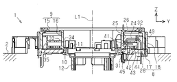
- the perspective view of the rotation connector of one Embodiment The longitudinal cross-sectional view of a rotation connector.
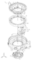
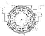
- the exploded perspective view of a rotation connector The perspective view of the rotation connector which removed the rotator.
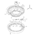
- Explanatory drawing which shows each rotation amount of a rotator and an intermediate member at the time of rotator rotation.
- Explanatory drawing which shows the winding amount of an electrical connection part The schematic diagram which shows the electrical connection part of another example.
- the rotary connector 1 for a vehicle is attached between a vehicle body 2 on the fixed side and a steering shaft 3 on the rotating side.
- the rotary connector 1 maintains communication between the vehicle body 2 and a steering wheel (not shown) even when the steering shaft 3 is rotated.
- the rotary connector 1 transmits the output signal Sout of the detection unit 4 provided on the steering wheel to the controller 5 on the vehicle body 2 side.
- the controller 5 includes an ECU (Electronic Control Unit) that manages the operation of the rotary connector 1, and determines the detection state of the detection unit 4 based on the output signal Sout.
- ECU Electronic Control Unit
- the detection unit 4 includes, for example, a switch and a sensor disposed on the steering wheel.
- the output signal Sout is not limited to an on / off signal detected by, for example, a switch or a sensor, but may be a data signal detected by sensors such as an image sensor.
- the rotary connector 1 includes a stator 8 attached and fixed to the vehicle body 2 and a rotator 9 that rotates with respect to the stator 8.
- the stator 8 and the rotator 9 are attached so as to overlap each other and are disposed on the same axis (on the axis L1).
- the axis L1 is the rotational axis of the steering shaft 3.
- Circular insertion holes 10 and 11 are formed at the centers of the stator 8 and the rotator 9, and the steering shaft 3 is inserted through the insertion holes 10 and 11.
- the rotator 9 is secured from the stator 8 by being fixed to the sleeve 12 with the stator 8 sandwiched therebetween.
- the rotator 9 and the sleeve 12 are integrally rotated with respect to the stator 8 around the steering shaft 3 and the axis L1 (in the direction of arrow R in FIG. 1).
- the rotator 9 includes a rotator base portion 15 having an insertion hole 11 through which a shaft portion 14 (in this example, the steering shaft 3) that rotates synchronously with the rotator 9, and along the insertion hole 11. And an inner wall portion 16 erected from the rotator base portion 15.
- the inner wall portion 16 is formed in an annular shape (annular shape) along the axis L1.
- the rotator base 15 and the inner wall 16 of this example are integrally formed.
- the inner wall portion 16 extends in the height direction of the rotary connector 1 (Z-axis direction in FIGS. 2 and 3).
- the stator 8 has a stator base 17 having an insertion hole 10 through which the shaft portion 14 (the steering shaft 3 in this example) passes, and an outer wall erected from the stator base 17 so as to face the inner wall portion 16 of the rotator 9. Part 18.
- the outer wall portion 18 is formed in an annular shape (annular shape) along the axis L1. In the case of this example, the stator base 17 and the outer wall 18 are assembled by a plurality of snap fits.
- the outer wall portion 18 extends in the height direction of the rotary connector 1 (Z-axis direction in FIGS. 2 and 3).
- the rotary connector 1 includes an electrical connection portion 24 that electrically connects the stator 8 and the rotator 9.
- the electrical connection portion 24 is an electric wire having a predetermined length that can permit relative rotation of the stator 8 and the rotator 9, and is preferably made of, for example, a wire (cord) that is insulated by rubber or the like.
- the electrical connection portion 24 is stored in a storage portion 25 formed between the stator 8 and the rotator 9. One end of the electrical connecting portion 24 is pulled out from the through hole 26 of the rotator 9 and connected to a connector (not shown) of the rotator 9, and the other end is pulled out from the through hole 28 of the stator 8 to be connected to the connector ( (Not shown).
- the rotary connector 1 includes a gear mechanism 31 that divides the rotation of the rotator 9 into small rotations.
- the gear mechanism 31 of this example converts the amount of movement of the electrical connecting portion 24 with respect to the stator 8 when the rotator 9 rotates to a small amount that is not synchronized with the rotation of the rotator 9 by transmitting the rotation of the rotator 9 at a reduced speed. To do.
- the rotary connector 1 includes an intermediate member 32 provided between the stator 8 and the rotator 9 so as to rotate on the same axis of the rotator 9 (around the axis L1).
- the intermediate member 32 includes an inner flange portion 33 formed in an annular shape, an insertion hole 34 through which the shaft portion 14 (the steering shaft 3 in this example) is passed, and a side wall portion protruding in an orthogonal direction with respect to the inner flange portion 33. 35 is formed.
- the side wall portion 35 is formed in an annular shape extending in one zone along the axis L1.
- the rotator 9 and the intermediate member 32 are connected via a gear mechanism 31.
- the gear mechanism 31 includes a first gear portion 41 provided on the rotator 9, a second gear portion 42 that meshes with the first gear portion 41 and rotates synchronously, and a second gear portion 42 that meshes with the second gear portion 42 and rotates synchronously. 3 gear part 43 and the 4th gear part 44 formed in the intermediate member 32 are provided.
- the first gear portion 41 is provided along the shaft portion 14 (the steering shaft 3 in this example) (around the axis L1) in the inner wall portion 16 of the rotator 9, and in this example, the first gear portion 41 is disposed around the axis L1. Yes.
- the second gear portion 42 is connected to the inner surface of the stator 8 via a pin 45 so as to be rotatable around the axis L2.
- the second gear part 42 is formed with a smaller diameter (smaller diameter gear) than the first gear part 41 and the fourth gear part 44.
- the third gear portion 43 is juxtaposed with the second gear portion 42 and connected to the inner surface of the stator 8 via a pin 46 so as to be rotatable around the axis L3.
- the third gear portion 43 is formed with a smaller diameter (smaller diameter gear) than the first gear portion 41 and the fourth gear portion 44, and is formed with substantially the same diameter as the second gear portion 42.
- the fourth gear portion 44 meshes with the third gear portion 43 and rotates synchronously therewith.
- the fourth gear portion 44 is provided around the shaft portion 14 (the steering shaft 3 in this example) (around the axis L1) in the annular side wall portion 35 of the intermediate member 32. In this example, the fourth gear portion 44 is entirely around the axis L1. Has been placed.
- the electrical connection portion 24 and the gear mechanism 31 are disposed in the same storage portion 25.
- the electrical connection portion 24 is passed through a groove 49 formed in the side wall portion 35 of the intermediate member 32.
- one end of the electrical connection portion 24 of this example is passed through the through hole 26 of the rotator 9, the middle is passed through the groove 49 of the intermediate member 32, and the other end is passed through the through hole 28 of the stator 8. Yes. Therefore, the electrical connection portion 24 of this example is provided across the three members of the stator 8, the rotator 9 and the intermediate member 32.
- the electrical connection portion 24 is configured to leave the maximum rotation amount (three revolutions) of the rotator 9. It has been bent for a long time. This is because, when the rotator 9 is rotated to the left or right from the neutral position, it is possible to rotate to the same maximum rotation amount (for example, three rotations from the neutral position for both the left and right).
- the rotator 9 is rotated in one direction (in the direction of arrow R1 in FIG. 6) from the neutral position. Since the rotator 9 rotates synchronously with the steering shaft 3, the rotator 9 rotates with the same rotation amount as the steering shaft 3. Here, it is assumed that the rotator 9 is rotated by the rotation amount S1 from the neutral position.
- the rotator 9 and the intermediate member 32 are connected by the gear mechanism 31, and when the rotator 9 rotates, the rotation of the rotator 9 increases from the first gear portion 41 having a large diameter to the second gear portion 42 having a small diameter ⁇
- the intermediate member 32 rotates by being transmitted through the third gear portion 43 ⁇ the fourth gear portion 44 having a large diameter.
- the rotation amount S 1 of the rotator 9 is decelerated and transmitted to the intermediate member 32, and the intermediate member 32 rotates with a rotation amount S 2 smaller than that of the rotator 9. That is, when the rotator 9 rotates the amount of rotation of “S1”, the intermediate member 32 rotates only “S2”.
- the electrical connection portion 24 of this example is attached so as to cross the stator 8, the rotator 9, and the intermediate member 32, and therefore, when the rotator 9 is rotated, between the rotator 9 and the intermediate member 32.
- the winding amount M2 of the electrical connection portion 24 is smaller than the winding amount M1 of the electrical connection portion 24 between the stator 8 and the intermediate member 32. That is, when the rotator 9 is rotated, the winding amount M2 of the electrical connection portion 24 between the rotator 9 and the intermediate member 32 can be made smaller than usual.
- the electrical connection portion 24 when the rotator 9 is rotated, the electrical connection portion 24 also moves according to the rotation of the rotator 9. At this time, the amount of movement of the electrical connection portion 24 with respect to the stator 8 (winding amount M2) is The rotation amount of the rotator 9 is reduced by the gear mechanism 31. In this way, the rotation of the rotator 9 and the movement of the electrical connection portion 24 are not synchronized, and even if the rotator 9 rotates around multiple rotations, the amount of movement of the electrical connection portion 24 (winding amount M2) can be suppressed to a small value. . Therefore, the structural complexity due to the large number of rotations of the rotator 9 can be avoided.
- the rotary connector 1 includes an intermediate member 32 that rotates together with the rotator 9, and the rotator 9 and the intermediate member 32 are connected via a gear mechanism 31.
- the electrical connection portion 24 is provided across the three members of the stator 8, the rotator 9, and the intermediate member 32. Thereby, the rotation of the rotator 9 is divided between the upstream and downstream of the intermediate member 32 through the gear mechanism 31.
- the amount of movement of the electrical connection portion 24 between the rotator 9 and the intermediate member 32 (winding amount M2) is larger than the amount of movement of the electrical connection portion 24 between the stator 8 and the intermediate member 32 (winding amount M1).
- the gear mechanism 31 has a structure including a first gear portion 41, a second gear portion 42, a third gear portion 43, and a fourth gear portion 44. Therefore, the structure of the gear mechanism 31 can be a simple structure including the four gear portions 41 to 44.
- the first gear portion 41 is provided along the rotation axis (around the axis L1) in the inner wall portion 16 of the rotator 9, and the fourth gear portion 44 is rotated around the rotation axis in the annular side wall portion 35 of the intermediate member 32. It is provided along (around the axis L1). Therefore, the first gear portion 41 can be provided in a sufficient space using the inner wall portion 16 of the rotator 9. Further, the fourth gear portion 44 can be provided in a sufficient space using the side wall portion 35 of the intermediate member 32.
- the electrical connection portion 24 is an electric wire (an example is a cord). Therefore, when the rotator 9 is rotated, it is possible to suppress the winding amount M2 of the electric wire in the middle of the rotation, which is advantageous in making it difficult for the electric wire to be danced or entangled.
- the dance of the electric wire refers to a state in which the electric wire moves in the housing of the rotary connector 1 and comes into contact with the inner wall of the housing. If this can be suppressed, generation of abnormal noise or the like can be prevented.
- the electrical connection portion 24 and the gear mechanism 31 are disposed in the same storage portion 25 formed by being surrounded by the stator 8 and the rotator 9. Therefore, it is not necessary to provide separate locations for storing the electrical connection portion 24 and the gear mechanism 31, which is further advantageous for simplifying the structure.
- the gear mechanism 31 and the electrical connection portion 24 can be operated in both the left and right rotations in accordance with the rotator 9 that can be rotated both left and right from the neutral position of rotation. Therefore, the structure of the gear mechanism 31 and the electrical connection portion 24 can be adapted to the structure of the rotator 9 that rotates to the left or right from the neutral position of rotation.
- the embodiment is not limited to the configuration described so far, and may be modified as follows.
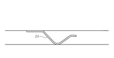
- the electrical connection portion 24 is not limited to a cord, and may be changed to a contact member such as a leaf spring brush contact, for example.
- a contact member for maintaining these conductions is provided between the rotator 9 and the intermediate member 32, and a contact member for maintaining these conductions is provided between the stator 8 and the intermediate member 32.
- the wall portion (side wall portion) of the rotator 9 is positioned on the radially outer side of the rotary connector 1, and the wall portion (side wall portion) of the stator 8 is It is good also as a shape located in radial inside.
- the rotator 9 and the intermediate member 32 have a plurality of holes (long holes) formed at equal intervals in the circumferential direction around the axis L1, but may have a shape in which these are omitted.
- the gear mechanism 31 is not limited to the shape having the first gear portion 41 to the fourth gear portion 44, and can be changed to another shape.
- the 1st gear part 41 and the 4th gear part 44 are not necessarily provided in a belt along the axis of rotation L1, and may be partially formed only in a predetermined range.
- the electric wire which is the electrical connection part 24 may be a multi-core wire (for example, a litz wire) having a plurality of wirings.
- the electric wire which is an electrical connection part should just be a wire which can conduct electricity not only with a code
- the electric wire which is the electrical connection part 24 is not restricted to being accommodated in the housing of the rotary connector 1, and may be exposed to the outside.
- the electrical connection part 24 should just be a member which can maintain the continuity between the stator 8 and the rotator 9 not only an electric wire or a leaf
- the rotary connector 1 may be one in which the intermediate member 32 is omitted.
- the rotary connector 1 is not limited to one that can rotate in both the left and right directions from the neutral position, but may be one that rotates only in either the left or right direction.
- the rotary connector 1 is not limited to being applied to a vehicle, but may be used for other devices and apparatuses.
Landscapes
- Engineering & Computer Science (AREA)
- Mechanical Engineering (AREA)
- Chemical & Material Sciences (AREA)
- Combustion & Propulsion (AREA)
- Transportation (AREA)
- Electric Cable Arrangement Between Relatively Moving Parts (AREA)
- Steering Controls (AREA)
Abstract
回転コネクタ(1)は、同一軸心上に配置されて相対回動されるステータ(8)及びロテータ(9)と、ステータ(8)及びロテータ(9)の間を電気接続する電気接続部(24)とを含む。回転コネクタ(1)はさらに、ロテータ(9)の回転を減速して伝達することにより、ロテータ(9)の回転時にステータ(8)に対し電気接続部(24)が動く量を、ロテータ(9)の回転に同期しない少ない量に変換するギヤ機構(31)を含む。
Description
本発明は、ステータ及びロテータの間の電気接続を向上する回転コネクタに関する。
従来、一方が他方に対して回転する2部品の間の電気的な接続を維持する回転コネクタとして、ステアリングロールコネクタが広く知られている。この種のステアリングロールコネクタには、フレキシブルケーブルを通じてステータ及びロテータの間を電気接続する技術が周知である(特許文献1等参照)。
この種の回転コネクタにおいては、ロテータがステアリングホイールと同期回転するが、ロテータが多回転されると、その分、フレキシブルケーブルが多量に巻き締め又は巻き緩めされるため、巻き締めや巻き緩みを許容できる構造を確保する必要があった。このため、ロテータ回転の多さによる構造上の複雑化を回避できる技術開発のニーズがあった。
本発明の目的は、ロテータ回転の多さによる構造上の複雑化を回避することができる回転コネクタを提供することにある。
一態様の回転コネクタは、同一軸心上に配置されるステータ及びロテータの相対回動を、前記ステータ及び前記ロテータの間の電気接続を維持しながら許容する構成において、前記ステータ及び前記ロテータの間を電気接続する電気接続部と、前記ロテータの回転を減速して伝達することにより、ロテータ回転時に前記ステータに対し前記電気接続部が動く量を、前記ロテータの回転に同期しない少ない量に変換するギヤ機構とを備えた。
本構成によれば、ロテータ回転時、ロテータ回転に準じて電気接続部も動くが、このときステータに対して電気接続部が動く量を、ギヤ機構によってロテータの回転に同期しない少ない量にする。すなわち、ロテータの回転と電気接続部の動きとが同期せず、仮にロテータが多回転で回っていても、電気接続部の動く量は少なく抑えられる。よって、ロテータ回転の多さによる構造上の複雑化を回避することが可能となる。
前記回転コネクタにおいて、前記ロテータと同一軸心上で回るように前記ステータ及び前記ロテータの間に設けられた中間部材を備え、前記ロテータ及び前記中間部材は、前記ギヤ機構を介して連結され、前記電気接続部は、前記ステータ、前記ロテータ及び前記中間部材の3部材を横断するように設けられていることが好ましい。この構成によれば、ロテータの回転が、ギヤ機構を通じて中間部材の上流と下流とで分割される。こうして、ロテータ及び中間部材の間において電気接続部が動く量よりも、ステータ及び中間部材の間において電気接続部が動く量を少なく抑えることにより、ロテータ回転の多さによる構造上の複雑化を回避することが可能となる。
前記回転コネクタにおいて、前記ギヤ機構は、前記ロテータに設けられた第1ギヤ部と、前記第1ギヤ部に噛み合わされて当該第1ギヤ部と同期回動する第2ギヤ部と、前記第2ギヤ部に噛み合わされて当該第2ギヤ部と同期回動する第3ギヤ部と、前記ロテータと同一軸心上で回るように前記ステータ及び前記ロテータの間に設けられた中間部材に形成され、前記第3ギヤ部に噛み合わされて当該第3ギヤ部と同期回動する第4ギヤ部とを備えることが好ましい。この構成によれば、ギヤ機構の構造を4つのギヤ部からなる簡素な構造とすることが可能となる。
前記回転コネクタにおいて、前記ロテータは、当該ロテータと同期回動する軸部を通す挿通孔を有したロテータ基部と、前記挿通孔に沿って立設された内壁部とを備え、前記第1ギヤ部は、前記ロテータの前記内壁部において回転の軸回りに沿って設けられ、前記第4ギヤ部は、前記中間部材の環状の側壁部において回転の軸回りに沿って設けられていることが好ましい。この構成によれば、ロテータの内壁部を利用して十分なスペースに第1ギヤ部を設けることが可能となる。また、中間部材の側壁部を利用して十分なスペースに第4ギヤ部を設けることが可能となる。
前記回転コネクタにおいて、前記電気接続部は、電線であることが好ましい。この構成によれば、ロテータ回転時、回転の途中で電線の巻き取り量を少なく抑えることが可能となるので、電線の踊りや絡まりを生じ難くするのに有利となる。
前記回転コネクタにおいて、前記電気接続部及び前記ギヤ機構は、前記ステータ及び前記ロテータにより囲まれて形成された同じ収納部に配置されていることが好ましい。この構成によれば、電気接続部及びギヤ機構を収納する箇所をそれぞれ別に設ける必要がないので、構造の簡素化に一層有利となる。
前記回転コネクタにおいて、前記ギヤ機構及び前記電気接続部は、回転の中立位置から左右両方向に回動可能である前記ロテータに合わせて、左右回転のいずれにも作動可能となっていることが好ましい。この構成によれば、ギヤ機構及び電気接続部の構造を、回転の中立位置から左右どちらにも回転するロテータの構造に合わせたものにすることが可能となる。
本発明によれば、ロテータ回転の多さによる構造上の複雑化を回避することができる。
以下、回転コネクタの一実施形態を図1~図7に従って説明する。
図1及び図2に示すように、車両用の回転コネクタ1は、固定側となる車体2と回動側となるステアリングシャフト3との間に取り付けられている。回転コネクタ1は、車体2及びステアリングホイール(図示略)の間の通信を、ステアリングシャフト3が回動されても維持するものである。回転コネクタ1は、ステアリングホイールに設けられた検知部4の出力信号Soutを、車体2側のコントローラ5に送信する。コントローラ5は、回転コネクタ1の作動を管理するECU(Electronic Control Unit)からなり、出力信号Soutを基に検知部4の検知状態を判断する。
図1及び図2に示すように、車両用の回転コネクタ1は、固定側となる車体2と回動側となるステアリングシャフト3との間に取り付けられている。回転コネクタ1は、車体2及びステアリングホイール(図示略)の間の通信を、ステアリングシャフト3が回動されても維持するものである。回転コネクタ1は、ステアリングホイールに設けられた検知部4の出力信号Soutを、車体2側のコントローラ5に送信する。コントローラ5は、回転コネクタ1の作動を管理するECU(Electronic Control Unit)からなり、出力信号Soutを基に検知部4の検知状態を判断する。
検知部4は、例えばステアリングホイールに配設されたスイッチやセンサ等からなる。また、出力信号Soutは、例えばスイッチやセンサにより検出されたオンオフ信号に限らず、例えば画像センサ等のセンサ類が検出したデータ信号でもよい。
回転コネクタ1は、車体2に取り付け固定されるステータ8と、ステータ8に対して回動するロテータ9とを備える。ステータ8及びロテータ9は、重ねられるように取り付けられるとともに、同一軸心(軸L1上)に配置されている。軸L1は、ステアリングシャフト3の回動軸心である。ステータ8及びロテータ9のそれぞれの中央には、円形状の挿通孔10,11が形成され、これら挿通孔10,11にステアリングシャフト3が挿通されている。ロテータ9は、間にステータ8を挟んだ状態でスリーブ12に固定されることにより、ステータ8から抜け止めされている。ステアリングシャフト3が回動したとき、ステータ8に対してロテータ9及びスリーブ12がステアリングシャフト3と軸L1回り(図1の矢印R方向)に一体回動する。
図2及び図3に示すように、ロテータ9は、ロテータ9と同期回動する軸部14(本例はステアリングシャフト3)を通す挿通孔11を有したロテータ基部15と、挿通孔11に沿ってロテータ基部15から立設された内壁部16とを備える。内壁部16は、軸L1回りに沿って環状(円環状)に形成されている。本例のロテータ基部15及び内壁部16は、一体形成されている。内壁部16は、回転コネクタ1の高さ方向(図2及び図3のZ軸方向)に延在する。
ステータ8は、軸部14(本例はステアリングシャフト3)を通す挿通孔10を有したステータ基部17と、ロテータ9の内壁部16と対向配置されるようにステータ基部17から立設された外壁部18とを備える。外壁部18は、軸L1回りに沿って環状(円環状)に形成されている。本例の場合、ステータ基部17及び外壁部18は、複数のスナップフィットによって組み付けられている。外壁部18は、回転コネクタ1の高さ方向(図2及び図3のZ軸方向)に延在する。
回転コネクタ1は、ステータ8及びロテータ9の間を電気接続する電気接続部24を備える。電気接続部24は、ステータ8及びロテータ9の相対回動を許容できる所定長さの電線であって、例えば周囲がゴム等で絶縁された線材(コード)からなることが好ましい。電気接続部24は、ステータ8及びロテータ9の間に形成された収納部25に収納されている。電気接続部24は、一端がロテータ9の通し孔26から引き出されてロテータ9のコネクタ(図示略)に接続されるとともに、他端がステータ8の通し孔28から引き出されてステータ8のコネクタ(図示略)に接続されている。
回転コネクタ1は、ロテータ9の回転を少回転に分割するギヤ機構31を備える。本例のギヤ機構31は、ロテータ9の回転を減速して伝達することにより、ロテータ9の回転時にステータ8に対し電気接続部24が動く量を、ロテータ9の回転に同期しない少ない量に変換する。
回転コネクタ1は、ロテータ9の同一軸心上(軸L1回り)で回るようにステータ8及びロテータ9の間に設けられた中間部材32を備える。中間部材32は、円環状に形成された内側鍔部33と、軸部14(本例はステアリングシャフト3)が通される挿通孔34と、内側鍔部33に対し直交方向に突出する側壁部35とを有した形状に形成されている。側壁部35は、軸L1回りに沿って一帯に延在した円環状に形成されている。ロテータ9及び中間部材32は、ギヤ機構31を介して連結されている。
ギヤ機構31は、ロテータ9に設けられた第1ギヤ部41と、第1ギヤ部41と噛み合って同期回動する第2ギヤ部42と、第2ギヤ部42と噛み合って同期回動する第3ギヤ部43と、中間部材32に形成された第4ギヤ部44とを備える。
第1ギヤ部41は、ロテータ9の内壁部16において軸部14(本例はステアリングシャフト3)回り(軸L1回り)に沿って設けられ、本例の場合、軸L1回り一帯に配置されている。
第2ギヤ部42は、ピン45を介して軸L2回りに回動可能にステータ8の内面に連結されている。第2ギヤ部42は、第1ギヤ部41及び第4ギヤ部44よりも小径(小径ギヤ)に形成されている。
第3ギヤ部43は、第2ギヤ部42に並設されるとともに、ピン46を介して軸L3回りに回動可能にステータ8の内面に連結されている。第3ギヤ部43は、第1ギヤ部41及び第4ギヤ部44よりも小径(小径ギヤ)に形成され、第2ギヤ部42と略同一径に形成されている。
第4ギヤ部44は、第3ギヤ部43と噛み合い、これと同期回動する。第4ギヤ部44は、中間部材32の環状の側壁部35において軸部14(本例はステアリングシャフト3)回り(軸L1回り)に沿って設けられ、本例の場合、軸L1回り一帯に配置されている。
図4に示すように、電気接続部24及びギヤ機構31は、同じ収納部25に配置されている。電気接続部24は、中間部材32の側壁部35に切り欠き形成された溝49に通されている。このように、本例の電気接続部24は、一端がロテータ9の通し孔26に通され、途中が中間部材32の溝49に通され、他端がステータ8の通し孔28に通されている。よって、本例の電気接続部24は、ステータ8、ロテータ9及び中間部材32の3部材を横断して設けられている。
次に、図5~図7を用いて、回転コネクタ1の作用及び効果を説明する。
図5に示すように、ロテータ9が回転の中立位置に位置するとき、すなわちステアリングホイールが中立位置に操作されているとき、電気接続部24は、ロテータ9の最大回転量(3回転)の余長分、撓んだ状態をとっている。これは、中立位置からロテータ9が左右のどちらに回転操作されたときも、左右同じ最大回転量(例えば、左右ともに中立位置から3回転)まで回ることを可能とするためである。
図5に示すように、ロテータ9が回転の中立位置に位置するとき、すなわちステアリングホイールが中立位置に操作されているとき、電気接続部24は、ロテータ9の最大回転量(3回転)の余長分、撓んだ状態をとっている。これは、中立位置からロテータ9が左右のどちらに回転操作されたときも、左右同じ最大回転量(例えば、左右ともに中立位置から3回転)まで回ることを可能とするためである。
図6に示すように、例えばロテータ9が中立位置から一方向(図6の矢印R1方向)に回転操作されたとする。ロテータ9は、ステアリングシャフト3と同期回転するので、ステアリングシャフト3と同じ回転量で回る。ここでは、ロテータ9が中立位置から回転量S1、回ったとする。
本例の場合、ロテータ9及び中間部材32がギヤ機構31によって連結され、ロテータ9の回転時、ロテータ9の回転が大径の第1ギヤ部41→小径の第2ギヤ部42→小径の第3ギヤ部43→大径の第4ギヤ部44を介して伝達されて、中間部材32が回る。このため、ロテータ9の回転時、ロテータ9の回転量S1が減速されて中間部材32に伝達されることになり、中間部材32は、ロテータ9よりも少ない回転量S2で回る。すなわち、ロテータ9が「S1」の回転量を回るところ、中間部材32は「S2」のみ回る。
図7に示すように、本例の電気接続部24はステータ8、ロテータ9及び中間部材32を横断するように取り付けられているので、ロテータ9の回転時、ロテータ9及び中間部材32の間の電気接続部24の巻き取り量M2が、ステータ8及び中間部材32の間の電気接続部24の巻き取り量M1よりも少なくなる。すなわち、ロテータ9の回転時、ロテータ9及び中間部材32の間の電気接続部24の巻き取り量M2を、通常よりも少なくすることが可能となる。
さて、本例の場合、ロテータ9の回転時、ロテータ9の回転に準じて電気接続部24も動くが、このときステータ8に対して電気接続部24が動く量(巻き取り量M2)を、ギヤ機構31によってロテータ9の回転量よりも少なくする。このように、ロテータ9の回転と電気接続部24の動きとが同期せず、仮にロテータ9が多回転で回っていても、電気接続部24の動く量(巻き取り量M2)は少なく抑えられる。よって、ロテータ9の回転の多さによる構造上の複雑化を回避することができる。
回転コネクタ1は、ロテータ9とともに回動する中間部材32を備え、ロテータ9及び中間部材32は、ギヤ機構31を介して連結されている。電気接続部24は、ステータ8、ロテータ9及び中間部材32の3部材を横断して設けられている。これにより、ロテータ9の回転が、ギヤ機構31を通じて中間部材32の上流と下流とで分割される。こうして、ステータ8及び中間部材32の間において電気接続部24が動く量(巻き取り量M1)よりも、ロテータ9及び中間部材32の間において電気接続部24が動く量(巻き取り量M2)を少なく抑えることにより、ロテータ9の回転の多さによる構造上の複雑化を回避することができる。
ギヤ機構31は、第1ギヤ部41、第2ギヤ部42、第3ギヤ部43及び第4ギヤ部44を有した構造をなしている。よって、ギヤ機構31の構造を、4つのギヤ部41~44からなる簡素な構造とすることができる。
第1ギヤ部41は、ロテータ9の内壁部16において回転の軸回り(軸L1回り)に沿って設けられ、第4ギヤ部44は、中間部材32の環状の側壁部35において回転の軸回り(軸L1回り)に沿って設けられている。よって、ロテータ9の内壁部16を利用して十分なスペースに第1ギヤ部41を設けることができる。また、中間部材32の側壁部35を利用して十分なスペースに第4ギヤ部44を設けることができる。
電気接続部24は、電線(一例はコード)である。よって、ロテータ9の回転時、回転の途中で電線の巻き取り量M2を少なく抑えることが可能となるので、電線の踊りや絡まりを生じ難くするのに有利となる。電線の踊りは、電線が回転コネクタ1のハウジング内で動いてハウジングの内壁等に接触する状態をいい、これを抑えることが可能となれば、異音等の発生を防止することができる。
電気接続部24及びギヤ機構31は、ステータ8及びロテータ9により囲まれて形成された同じ収納部25に配置されている。よって、電気接続部24及びギヤ機構31を収納する箇所を、それぞれ別に設ける必要がないので、構造の簡素化に一層有利となる。
ギヤ機構31及び電気接続部24は、回転の中立位置から左右両方に回動可能であるロテータ9に合わせて、左右回転のいずれにも作動可能となっている。よって、ギヤ機構31及び電気接続部24の構造を、回転の中立位置から左右どちらにも回転するロテータ9の構造に合わせたものにすることができる。
本例の場合、多種多様な電気接続部24(電線)を用いることが可能となるので、ステアリングホイールの多機能化に伴う多チャンネル化及び高速通信を実現することができる。
なお、実施形態はこれまでに述べた構成に限らず、以下の態様に変更してもよい。
・図8に示すように、電気接続部24は、コードに限らず、例えば板ばねブラシ接点などの接点部材に変更してもよい。この場合、ロテータ9及び中間部材32の間に、これらの導通を維持する接点部材が設けられ、ステータ8及び中間部材32の間に、これらの導通を維持する接点部材が設けられる。この場合も、ロテータ9の回転を分割して、ロテータ9の回転の多さによる構造上の複雑化を回避することができる。
・図8に示すように、電気接続部24は、コードに限らず、例えば板ばねブラシ接点などの接点部材に変更してもよい。この場合、ロテータ9及び中間部材32の間に、これらの導通を維持する接点部材が設けられ、ステータ8及び中間部材32の間に、これらの導通を維持する接点部材が設けられる。この場合も、ロテータ9の回転を分割して、ロテータ9の回転の多さによる構造上の複雑化を回避することができる。
・図9に示すように、回転コネクタ1のハウジングは、ロテータ9の壁部(側壁部)が回転コネクタ1の径方向外側に位置し、ステータ8の壁部(側壁部)が回転コネクタ1の径方向内側に位置する形状としてもよい。
・ロテータ9や中間部材32は、軸L1回りの周方向に孔部(長孔)が等間隔に複数形成されているが、これらを省略した形状でもよい。
・ギヤ機構31は、第1ギヤ部41~第4ギヤ部44を有する形状に限定されず、他の形状のものに変更可能である。
・ギヤ機構31は、第1ギヤ部41~第4ギヤ部44を有する形状に限定されず、他の形状のものに変更可能である。
・第1ギヤ部41及び第4ギヤ部44は、回転の軸L1回りに沿って一帯に設けられることに限らず、所定の範囲にのみ部分的に形成されてもよい。
・電気接続部24である電線は、複数の配線を有する多芯線(例えばリッツ線)でもよい。
・電気接続部24である電線は、複数の配線を有する多芯線(例えばリッツ線)でもよい。
・電気接続部である電線は、コードに限らず、電気を通すことができる線材であればよい。
・電気接続部24である電線は、回転コネクタ1のハウジング内に収納されることに限らず、外部に露出していてもよい。
・電気接続部24である電線は、回転コネクタ1のハウジング内に収納されることに限らず、外部に露出していてもよい。
・電気接続部24は、電線や板ばねブラシ接点に限らず、ステータ8及びロテータ9の間の導通を維持できる部材であればよい。
・電気接続部24及びギヤ機構31は、それぞれ異なる箇所に収納されてもよい。
・電気接続部24及びギヤ機構31は、それぞれ異なる箇所に収納されてもよい。
・回転コネクタ1は、中間部材32が省略されたものでもよい。
・回転コネクタ1は、中立位置から左右両方向に回転できるものに限らず、左右どちらか一方にのみ回転するものでもよい。
・回転コネクタ1は、中立位置から左右両方向に回転できるものに限らず、左右どちらか一方にのみ回転するものでもよい。
・回転コネクタ1は、車両に適用されることに限らず、他の機器や装置に使用してもよい。
Claims (7)
- 同一軸心上に配置されるステータ及びロテータの相対回動を、前記ステータ及び前記ロテータの間の電気接続を維持しながら許容する回転コネクタにおいて、
前記ステータ及び前記ロテータの間を電気接続する電気接続部と、
前記ロテータの回転を減速して伝達することにより、前記ロテータの回転時に前記ステータに対し前記電気接続部が動く量を、前記ロテータの回転に同期しない少ない量に変換するギヤ機構と
を備えたことを特徴とする回転コネクタ。 - 前記ロテータと同一軸心上で回るように前記ステータ及び前記ロテータの間に設けられた中間部材を備え、
前記ロテータ及び前記中間部材は、前記ギヤ機構を介して連結され、
前記電気接続部は、前記ステータ、前記ロテータ及び前記中間部材を横断するように設けられている
請求項1に記載の回転コネクタ。 - 前記ギヤ機構は、
前記ロテータに設けられた第1ギヤ部と、
前記第1ギヤ部に噛み合わされて当該第1ギヤ部と同期回動する第2ギヤ部と、
前記第2ギヤ部に噛み合わされて当該第2ギヤ部と同期回動する第3ギヤ部と、
前記ロテータと同一軸心上で回るように前記ステータ及び前記ロテータの間に設けられた中間部材に形成され、前記第3ギヤ部に噛み合わされて当該第3ギヤ部と同期回動する第4ギヤ部とを備える
請求項1又は2に記載の回転コネクタ。 - 前記ロテータは、当該ロテータと同期回動する軸部を通す挿通孔を有したロテータ基部と、前記挿通孔に沿って前記ロテータ基部から立設された内壁部とを備え、
前記第1ギヤ部は、前記ロテータの前記内壁部において回転の軸回りに沿って設けられ、
前記第4ギヤ部は、前記中間部材の環状の側壁部において回転の軸回りに沿って設けられている
請求項3に記載の回転コネクタ。 - 前記電気接続部は、電線である
請求項1~4のうちいずれか一項に記載の回転コネクタ。 - 前記電気接続部及び前記ギヤ機構は、前記ステータ及び前記ロテータにより囲まれて形成された同じ収納部に配置されている
請求項1~5のうちいずれか一項に記載の回転コネクタ。 - 前記ギヤ機構及び前記電気接続部は、回転の中立位置から左右両方向に回動可能である前記ロテータに合わせて、左右回転のいずれにも作動可能となっている
請求項1~6のうちいずれか一項に記載の回転コネクタ。
Applications Claiming Priority (2)
| Application Number | Priority Date | Filing Date | Title |
|---|---|---|---|
| JP2016-177905 | 2016-09-12 | ||
| JP2016177905A JP2018045786A (ja) | 2016-09-12 | 2016-09-12 | 回転コネクタ |
Publications (1)
| Publication Number | Publication Date |
|---|---|
| WO2018047481A1 true WO2018047481A1 (ja) | 2018-03-15 |
Family
ID=61561791
Family Applications (1)
| Application Number | Title | Priority Date | Filing Date |
|---|---|---|---|
| PCT/JP2017/026508 Ceased WO2018047481A1 (ja) | 2016-09-12 | 2017-07-21 | 回転コネクタ |
Country Status (2)
| Country | Link |
|---|---|
| JP (1) | JP2018045786A (ja) |
| WO (1) | WO2018047481A1 (ja) |
Cited By (1)
| Publication number | Priority date | Publication date | Assignee | Title |
|---|---|---|---|---|
| CN116774360A (zh) * | 2023-06-25 | 2023-09-19 | 深圳市默孚龙科技有限公司 | 一种用于光纤线缆固定圈数旋转传输的连接器 |
Citations (2)
| Publication number | Priority date | Publication date | Assignee | Title |
|---|---|---|---|---|
| JPH0822877A (ja) * | 1994-07-08 | 1996-01-23 | Kansei Corp | 通電装置 |
| JP2004120900A (ja) * | 2002-09-26 | 2004-04-15 | Tokai Rika Co Ltd | ステアリングロールコネクタとステアリングホイールとの接続構造 |
-
2016
- 2016-09-12 JP JP2016177905A patent/JP2018045786A/ja active Pending
-
2017
- 2017-07-21 WO PCT/JP2017/026508 patent/WO2018047481A1/ja not_active Ceased
Patent Citations (2)
| Publication number | Priority date | Publication date | Assignee | Title |
|---|---|---|---|---|
| JPH0822877A (ja) * | 1994-07-08 | 1996-01-23 | Kansei Corp | 通電装置 |
| JP2004120900A (ja) * | 2002-09-26 | 2004-04-15 | Tokai Rika Co Ltd | ステアリングロールコネクタとステアリングホイールとの接続構造 |
Cited By (1)
| Publication number | Priority date | Publication date | Assignee | Title |
|---|---|---|---|---|
| CN116774360A (zh) * | 2023-06-25 | 2023-09-19 | 深圳市默孚龙科技有限公司 | 一种用于光纤线缆固定圈数旋转传输的连接器 |
Also Published As
| Publication number | Publication date |
|---|---|
| JP2018045786A (ja) | 2018-03-22 |
Similar Documents
| Publication | Publication Date | Title |
|---|---|---|
| CN102822011B (zh) | 旋转连接器装置 | |
| EP3010684B1 (en) | A rotary joint of a robot and the robot including the same | |
| JP6708953B2 (ja) | ロボット | |
| JP5117528B2 (ja) | 回転コネクタ装置 | |
| JP6155459B2 (ja) | 遊技機の可動装飾装置 | |
| EP2500217B1 (en) | Rotary connector | |
| JP2011207402A5 (ja) | ||
| JPH02215071A (ja) | コネクタ装置 | |
| US5890921A (en) | Rotary connector | |
| JP7054646B2 (ja) | 回転構造体 | |
| WO2018047481A1 (ja) | 回転コネクタ | |
| KR102180737B1 (ko) | 모터 및 이를 포함하는 동력 전달 장치 | |
| WO2017169580A1 (ja) | 回転アクチュエータおよびロボット | |
| JP2016178807A (ja) | 巻取装置 | |
| WO2018051755A1 (ja) | 回転コネクタ | |
| EP2636925B1 (en) | Rotation transmission mechanism and rotary connector | |
| JP2018045787A (ja) | 回転コネクタ | |
| JP2018129157A (ja) | 回転コネクタ | |
| JP2018045860A (ja) | 回転コネクタ | |
| JP2018045862A (ja) | 回転コネクタ | |
| JP2018045861A (ja) | 回転コネクタ | |
| JP2020170646A (ja) | 回転コネクタ及び回転検出装置 | |
| WO2018061230A1 (ja) | ケーブルラップ機構 | |
| JP2018045962A (ja) | 回転コネクタ | |
| JPH0220791Y2 (ja) |
Legal Events
| Date | Code | Title | Description |
|---|---|---|---|
| 121 | Ep: the epo has been informed by wipo that ep was designated in this application |
Ref document number: 17848426 Country of ref document: EP Kind code of ref document: A1 |
|
| NENP | Non-entry into the national phase |
Ref country code: DE |
|
| 122 | Ep: pct application non-entry in european phase |
Ref document number: 17848426 Country of ref document: EP Kind code of ref document: A1 |