WO2018043529A1 - 水蒸気バリア性を有する位相差膜及びその製造方法 - Google Patents
水蒸気バリア性を有する位相差膜及びその製造方法 Download PDFInfo
- Publication number
- WO2018043529A1 WO2018043529A1 PCT/JP2017/031072 JP2017031072W WO2018043529A1 WO 2018043529 A1 WO2018043529 A1 WO 2018043529A1 JP 2017031072 W JP2017031072 W JP 2017031072W WO 2018043529 A1 WO2018043529 A1 WO 2018043529A1
- Authority
- WO
- WIPO (PCT)
- Prior art keywords
- group
- carbon atoms
- integer
- retardation film
- halogen atom
- Prior art date
- Legal status (The legal status is an assumption and is not a legal conclusion. Google has not performed a legal analysis and makes no representation as to the accuracy of the status listed.)
- Ceased
Links
- 0 C*(C)[Al]c(cc1)cc2c1cc(**C(C1=C=C(C)C11)=CC=C1C(C)(C)C=CC(*)=O)cc2 Chemical compound C*(C)[Al]c(cc1)cc2c1cc(**C(C1=C=C(C)C11)=CC=C1C(C)(C)C=CC(*)=O)cc2 0.000 description 2
Classifications
-
- G—PHYSICS
- G02—OPTICS
- G02B—OPTICAL ELEMENTS, SYSTEMS OR APPARATUS
- G02B5/00—Optical elements other than lenses
- G02B5/30—Polarising elements
- G02B5/3083—Birefringent or phase retarding elements
-
- C—CHEMISTRY; METALLURGY
- C08—ORGANIC MACROMOLECULAR COMPOUNDS; THEIR PREPARATION OR CHEMICAL WORKING-UP; COMPOSITIONS BASED THEREON
- C08F—MACROMOLECULAR COMPOUNDS OBTAINED BY REACTIONS ONLY INVOLVING CARBON-TO-CARBON UNSATURATED BONDS
- C08F220/00—Copolymers of compounds having one or more unsaturated aliphatic radicals, each having only one carbon-to-carbon double bond, and only one being terminated by only one carboxyl radical or a salt, anhydride ester, amide, imide or nitrile thereof
- C08F220/02—Monocarboxylic acids having less than ten carbon atoms; Derivatives thereof
- C08F220/10—Esters
- C08F220/26—Esters containing oxygen in addition to the carboxy oxygen
- C08F220/30—Esters containing oxygen in addition to the carboxy oxygen containing aromatic rings in the alcohol moiety
- C08F220/303—Esters containing oxygen in addition to the carboxy oxygen containing aromatic rings in the alcohol moiety and one or more carboxylic moieties in the chain
-
- G—PHYSICS
- G02—OPTICS
- G02B—OPTICAL ELEMENTS, SYSTEMS OR APPARATUS
- G02B1/00—Optical elements characterised by the material of which they are made; Optical coatings for optical elements
- G02B1/08—Optical elements characterised by the material of which they are made; Optical coatings for optical elements made of polarising materials
-
- G—PHYSICS
- G02—OPTICS
- G02B—OPTICAL ELEMENTS, SYSTEMS OR APPARATUS
- G02B5/00—Optical elements other than lenses
- G02B5/30—Polarising elements
-
- G—PHYSICS
- G02—OPTICS
- G02B—OPTICAL ELEMENTS, SYSTEMS OR APPARATUS
- G02B5/00—Optical elements other than lenses
- G02B5/30—Polarising elements
- G02B5/3016—Polarising elements involving passive liquid crystal elements
-
- G—PHYSICS
- G09—EDUCATION; CRYPTOGRAPHY; DISPLAY; ADVERTISING; SEALS
- G09F—DISPLAYING; ADVERTISING; SIGNS; LABELS OR NAME-PLATES; SEALS
- G09F9/00—Indicating arrangements for variable information in which the information is built-up on a support by selection or combination of individual elements
- G09F9/30—Indicating arrangements for variable information in which the information is built-up on a support by selection or combination of individual elements in which the desired character or characters are formed by combining individual elements
-
- H—ELECTRICITY
- H05—ELECTRIC TECHNIQUES NOT OTHERWISE PROVIDED FOR
- H05B—ELECTRIC HEATING; ELECTRIC LIGHT SOURCES NOT OTHERWISE PROVIDED FOR; CIRCUIT ARRANGEMENTS FOR ELECTRIC LIGHT SOURCES, IN GENERAL
- H05B33/00—Electroluminescent light sources
- H05B33/02—Details
-
- H—ELECTRICITY
- H10—SEMICONDUCTOR DEVICES; ELECTRIC SOLID-STATE DEVICES NOT OTHERWISE PROVIDED FOR
- H10K—ORGANIC ELECTRIC SOLID-STATE DEVICES
- H10K59/00—Integrated devices, or assemblies of multiple devices, comprising at least one organic light-emitting element covered by group H10K50/00
- H10K59/80—Constructional details
- H10K59/87—Passivation; Containers; Encapsulations
- H10K59/873—Encapsulations
-
- H—ELECTRICITY
- H10—SEMICONDUCTOR DEVICES; ELECTRIC SOLID-STATE DEVICES NOT OTHERWISE PROVIDED FOR
- H10K—ORGANIC ELECTRIC SOLID-STATE DEVICES
- H10K59/00—Integrated devices, or assemblies of multiple devices, comprising at least one organic light-emitting element covered by group H10K50/00
- H10K59/80—Constructional details
- H10K59/8791—Arrangements for improving contrast, e.g. preventing reflection of ambient light
Definitions
- the present invention relates to a retardation film having a water vapor barrier property and a method for producing the same.
- An extremely high water vapor barrier property is required for a substrate for an organic EL display.
- a resin substrate having a water vapor barrier property a substrate in which a water vapor barrier layer is formed on the surface of a base material made of resin has been used.
- Patent Document 1 an inorganic layer formed by a counter target sputtering method, an inorganic layer formed by a vacuum deposition method, an inorganic layer formed by a chemical vapor deposition method, and a vacuum deposition method are formed on a plastic film as a substrate.
- a gas barrier film having inorganic layers in this order is described.
- this technique has a problem in terms of productivity because the manufacturing process is complicated.
- a retardation plate is used in order to suppress external light reflection and improve visibility. If a high water vapor barrier property can be imparted to the retardation plate, it is possible to simultaneously have a function as a substrate of an organic EL display and a function as a retardation film.
- the gas barrier film using an inorganic material has poor flexibility and is brittle, there is a problem that it cannot satisfy the demand for flexibility.
- the present invention has been made in view of the above circumstances, and provides a retardation film having a water vapor barrier property, which can be manufactured by a simple method at a lower cost than conventional methods, and can be manufactured using an organic material, and a manufacturing method thereof. With the goal.
- the inventors of the present invention have, as a result, a retardation film containing a polymer that can exhibit liquid crystallinity having a predetermined photosensitive side chain, also has a water vapor barrier property,
- the present invention was completed by finding that it can be produced by a simpler method.
- the present invention provides a retardation film having the following water vapor barrier property and a method for producing the same.
- a retardation film having a water vapor barrier property comprising a liquid crystalline polymer having a photosensitive side chain and having a thickness of more than 300 nm and not more than 50,000 nm.
- 2. 1. The retardation film according to 1, wherein the photosensitive side chain undergoes photocrosslinking, photoisomerization, or photofleece transition.
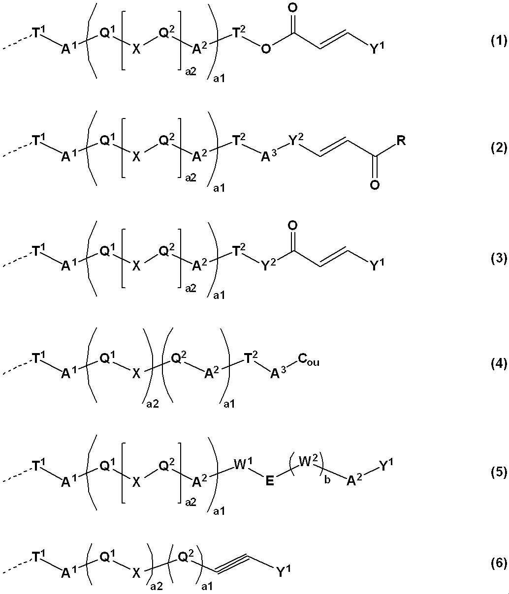
- 3. The retardation film according to 2, wherein the photosensitive side chain is at least one selected from groups represented by the following formulas (1) to (6).
- a 1 , A 2 and A 3 are each independently a single bond, —O—, —CH 2 —, —C ( ⁇ O) —O—, —O—C ( ⁇ O) —, Represents —C ( ⁇ O) —NH—, —NH—C ( ⁇ O) —, —CH ⁇ CH—C ( ⁇ O) —O— or —O—C ( ⁇ O) —CH ⁇ CH—;
- T 1 represents an alkylene group having 1 to 12 carbon atoms which may be substituted with a halogen atom;
- T 2 represents a single bond or an alkylene group having 1 to 12 carbon atoms which may be substituted with a halogen atom;
- Y 1 is a monovalent aromatic group selected from a phenyl group, a naphthyl group, a biphenylyl group, a furanyl group, and a pyrrolyl group, a monovalent cyclic aliphatic hydrocarbon group having 5
- the selected 2 to 6 groups are bonded to each other through a linking group A 2, and a part of the hydrogen atoms bonded to these groups is —COOR 0 (R 0 is a hydrogen atom or a carbon number of 1 to 5; Represents an alkyl group.), —NO 2 , —CN, —CH ⁇ C (CN) 2 , —CH ⁇ CH—CN, a halogen atom, an alkyl group having 1 to 5 carbon atoms, or an alkoxy group having 1 to 5 carbon atoms May be substituted with; Y 2 represents a divalent aromatic group selected from a phenylene group, a naphthalenediyl group, a biphenylylene group, a furandiyl group, and a pyrroldiyl group, a divalent cyclic aliphatic hydrocarbon group having 5 to 8 carbon atoms, or a substitution thereof.
- -CH CH-CN, a halogen atom, an alkyl group having 1 to 5 carbon atoms, or an alkoxy group having 1 to 5 carbon atoms;
- R represents a hydroxy group or an alkoxy group having 1 to 6 carbon atoms, or the same definition as Y 1 ;
- X is a single bond, —C ( ⁇ O) —O—, —O—C ( ⁇ O) —, —N ⁇ N—, —CH ⁇ CH—, —C ⁇ C—, —CH ⁇ CH—C.
- C ou represents a coumarin-6-yl group or a coumarin-7-yl group, and a part of the hydrogen atoms bonded thereto are —NO 2 , —CN, —CH ⁇ C (CN) 2 , —CH ⁇ CH -CN, a halogen atom, an alkyl group having 1 to 5 carbon atoms or an alkoxy group having 1 to 5 carbon atoms may be substituted;
- Q 1 and Q 2 are each independently a divalent aromatic group selected from a phenylene group, a naphthalenediyl group, a biphenylylene group, a frangyl group, and a pyrroldiyl group, and a divalent cyclic aliphatic carbon group having 5 to 8 carbon atoms.
- Q 1 or Q 2 on the side to which —CH ⁇ CH— is bonded is a divalent aromatic group, and when Q 1 is 2 or more, each Q 1 is the same However, they may be different, and when Q 2 is 2 or more, each Q 2 may be the same or different;
- E represents —C ( ⁇ O) —O— or —O—C ( ⁇ O) —;
- W 1 and W 2 are each independently 2-6 groups selected from a phenylene group, a naphthalenediyl group, a biphenylylene group, a frangyl group, a pyrrolediyl group, or a substituent thereof bonded via a linking group
- a 2 Represents a group of a1 represents 0 or 1; a2 represents an integer of
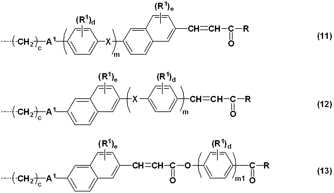
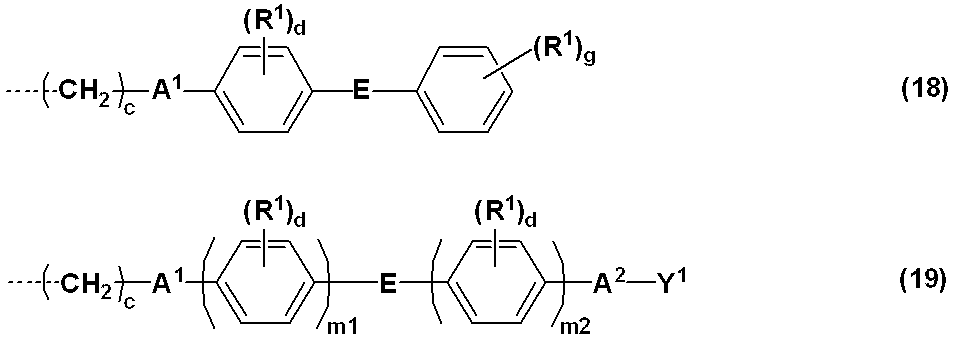
- a retardation film according to 3, wherein the photosensitive side chain is selected from the groups represented by the following formulas (11) to (13). (Wherein A 1 , R, R 1 , X, c, d, m1 and the broken line are the same as above; e represents an integer of 0 to 6) 6). 3. The retardation film according to 3, wherein the photosensitive side chain is a group represented by the following formula (14) or (15). (In the formula, A 1 , R 1 , Y 1 , c, d, m1, m2 and the broken line are the same as described above.) 7). 3. The retardation film according to 3, wherein the photosensitive side chain is a group represented by the following formula (16) or (17).
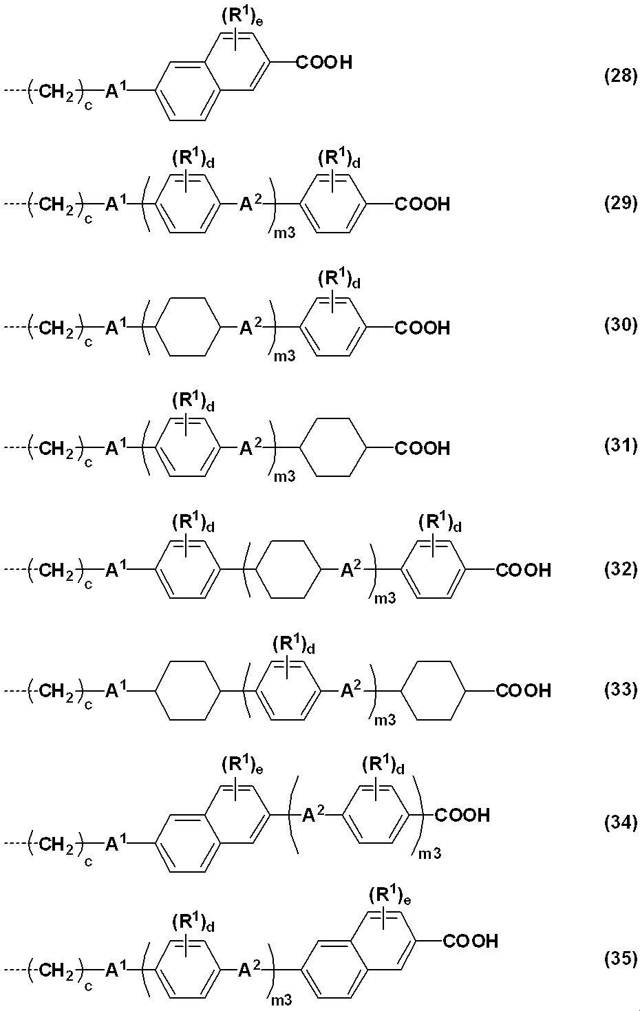
- liquid crystalline polymer further contains at least one liquid crystalline side chain selected from the groups represented by the following formulas (21) to (35).
- R 2 is a hydrogen atom, —NO 2 , —CN, —CH ⁇ C (CN) 2 , —CH ⁇ CH—CN, halogen atom, phenyl group, naphthyl group, biphenylyl group, furanyl group, monovalent nitrogen-containing Represents a heterocyclic group, a cyclic aliphatic hydrocarbon group having 5 to 8 carbon atoms, an alkyl group having 1 to 12 carbon atoms, or an alkoxy group having 1 to 12 carbon atoms; Y 3 represents a phenyl group, a naphthyl group, a biphenylyl group, a furanyl group, a monovalent nitrogen-containing heterocyclic group, a cyclic aliphatic hydrocarbon group having 5 to 8 carbon atoms, or a substituent thereof selected from 2
- R C represents a hydrogen atom, an alkyl group having 1 to 3 carbon atoms, a carboxyl group or a carboxylmethyl group
- R E represents a hydroxy group, an alkyl or alkoxy group having 1 to 10 carbon atoms, or a phenyl group
- a broken line represents a bond to R A or R B .
- An organic EL display comprising the retardation film according to any one of 1 to 13.
- a composition for forming a retardation film containing a resin component containing a liquid crystalline polymer having a photosensitive side chain and an organic solvent is applied to a substrate to form a coating film having a thickness of more than 300 nm and not more than 50,000 nm.
- Process, Production of a retardation film having a water vapor barrier property comprising a step of irradiating the coating film with polarized ultraviolet light, and a step of heating the film irradiated with polarized ultraviolet light to obtain a film having a film thickness of more than 300 nm and not more than 50,000 nm Method. 16. 15.
- the retardation film of the present invention has both a high water vapor barrier property and a function as a retardation film, and can be suitably used for a display device such as an organic EL display. Further, the retardation film of the present invention can be produced by a simple method at a lower cost than the conventional one, and the productivity is also good.
- the retardation film having water vapor barrier properties of the present invention contains a liquid crystalline polymer having a photosensitive side chain, and has a film thickness of more than 300 nm and 50,000 nm or less.
- the structure of the photosensitive side chain is not particularly limited, but is preferably a structure that undergoes a crosslinking reaction, isomerization reaction, or photofleece rearrangement in response to light, and more preferably a structure that undergoes a crosslinking reaction or photofleece rearrangement. Even more preferred is one that causes
- the photosensitive side chain is preferably at least one selected from the groups represented by the following formulas (1) to (6).
- a 1 , A 2 and A 3 are each independently a single bond, —O—, —CH 2 —, —C ( ⁇ O) —O—, —O—C ( ⁇ O) —, — C ( ⁇ O) —NH—, —NH—C ( ⁇ O) —, —CH ⁇ CH—C ( ⁇ O) —O— or —O—C ( ⁇ O) —CH ⁇ CH— is represented.
- T 1 represents an alkylene group having 1 to 12 carbon atoms which may be substituted with a halogen atom.
- T 2 represents a single bond or an alkylene group having 1 to 12 carbon atoms which may be substituted with a halogen atom.
- Y 1 is a monovalent aromatic group selected from a phenyl group, a naphthyl group, a biphenylyl group, a furanyl group, and a pyrrolyl group, a monovalent cyclic aliphatic hydrocarbon group having 5 to 8 carbon atoms, or a substituent thereof.
- the selected 2 to 6 groups are bonded to each other through a linking group A 2, and a part of the hydrogen atoms bonded to these groups is —COOR 0 (R 0 is a hydrogen atom or a carbon number of 1 to 5; Represents an alkyl group.), —NO 2 , —CN, —CH ⁇ C (CN) 2 , —CH ⁇ CH—CN, a halogen atom, an alkyl group having 1 to 5 carbon atoms, or an alkoxy group having 1 to 5 carbon atoms May be substituted.
- Y 2 represents a divalent aromatic group selected from a phenylene group, a naphthalenediyl group, a biphenylylene group, a furandiyl group, and a pyrroldiyl group, a divalent cyclic aliphatic hydrocarbon group having 5 to 8 carbon atoms, or a substitution thereof.
- R represents a hydroxy group, an alkoxy group having 1 to 6 carbon atoms, or the same definition as Y 1 .
- X is a single bond, —C ( ⁇ O) —O—, —O—C ( ⁇ O) —, —N ⁇ N—, —CH ⁇ CH—, —C ⁇ C—, —CH ⁇ CH—C. ( ⁇ O) —O— or —O—C ( ⁇ O) —CH ⁇ CH—, and when the number of X is 2 or more, each X may be the same or different.
- C ou represents a coumarin-6-yl group or a coumarin-7-yl group, and a part of the hydrogen atoms bonded thereto are —NO 2 , —CN, —CH ⁇ C (CN) 2 , —CH ⁇ CH -CN, a halogen atom, an alkyl group having 1 to 5 carbon atoms, or an alkoxy group having 1 to 5 carbon atoms may be substituted.
- Q 1 and Q 2 are each independently a divalent aromatic group selected from a phenylene group, a naphthalenediyl group, a biphenylylene group, a frangyl group, and a pyrroldiyl group, and a divalent cyclic aliphatic carbon group having 5 to 8 carbon atoms.
- X is —CH ⁇ CH—CO—O— or —O—CO;
- Q 1 or Q 2 on the side to which —CH ⁇ CH— is bonded is a divalent aromatic group, and when Q 1 is 2 or more, each Q 1 is the same However, they may be different, and when the number of Q 2 is 2 or more, each Q 2 may be the same or different.
- W 1 and W 2 are each independently 2-6 groups selected from a phenylene group, a naphthalenediyl group, a biphenylylene group, a frangyl group, a pyrrolediyl group, or a substituent thereof bonded via a linking group
- a 2 Represents a group formed by
- a1 represents 0 or 1.
- a2 represents an integer of 0 to 2.
- a a1 and a2 are both 0, when T 2 is a single bond, A 1 represents a single bond.
- a1 is 1, when T 2 is a single bond, A 2 represents a single bond.
- b represents 0 or 1.
- a broken line represents a bond with the main chain.
- a 1 , A 2 , A 3 , Y 1 , Y 2 , R, X and the broken line are the same as described above, but when n is 0, A 2 is a single bond.
- R 1 represents —NO 2 , —CN, a halogen atom, an alkyl group having 1 to 5 carbon atoms, or an alkoxy group having 1 to 5 carbon atoms.
- c represents an integer of 1 to 12.
- m represents an integer of 0-2.
- m1 and m2 each independently represents an integer of 1 to 3.
- d represents an integer of 0 to 4.
- n represents an integer of 0 to 12.
- alkyl group having 1 to 5 carbon atoms examples include methyl, ethyl, n-propyl, isopropyl, n-butyl, isobutyl, sec-butyl, tert-butyl, and n-pentyl. Can be mentioned.
- alkoxy group having 1 to 5 carbon atoms include methoxy group, ethoxy group, n-propoxy group, isopropoxy group, n-butoxy group, isobutoxy group, sec-butoxy group, tert-butoxy group, and n-pentyloxy group. Etc.
- the photosensitive side chain preferably reacts with light having a wavelength in the range of 250 to 400 nm.
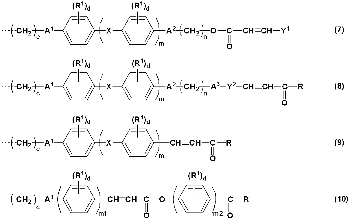
- photosensitive side chain those represented by the formulas (7), (8), (9), (14), and (15) are particularly preferable.
- the liquid crystalline polymer has a photosensitive side chain bonded to the main chain, and can cause a crosslinking reaction, an isomerization reaction, or a light fleece rearrangement in response to light.
- the structure of the side chain having photosensitivity is not particularly limited, but a structure that undergoes a crosslinking reaction or photofleece rearrangement in response to light is preferred, and a structure that undergoes a crosslinking reaction is more preferred.
- the structure of the polymer film having a photosensitive side chain capable of exhibiting liquid crystallinity is not particularly limited as long as it satisfies such characteristics, but it is preferable to have a rigid mesogenic component in the side chain structure.
- the liquid crystalline polymer preferably exhibits liquid crystallinity in a temperature range of 50 to 300 ° C.
- the expression temperature of the liquid crystal is more preferably 60 to 280 ° C, still more preferably 70 to 250 ° C, and further preferably 80 to 200 ° C. If the liquid crystalline expression temperature is within the above range, a film capable of stably maintaining the obtained water vapor barrier property and retardation for a long time even when exposed to external stress such as heat or light is produced. be able to.
- the liquid crystalline polymer preferably includes a liquid crystalline side chain having a rigid mesogenic site in addition to the photosensitive side chain.
- a side chain is preferably at least one selected from the groups represented by the following formulas (21) to (35).
- a 1 , A 2 , E, R 1 , c, d, e, m1, m2 and the broken line are the same as described above.
- R 2 is a hydrogen atom, —NO 2 , —CN, —CH ⁇ C (CN) 2 , —CH ⁇ CH—CN, halogen atom, phenyl group, naphthyl group, biphenylyl group, furanyl group, monovalent nitrogen-containing
- a heterocyclic ring-containing group, a cyclic aliphatic hydrocarbon group having 5 to 8 carbon atoms, an alkyl group having 1 to 12 carbon atoms, or an alkoxy group having 1 to 12 carbon atoms is represented.
- Y 3 represents a phenyl group, a naphthyl group, a biphenylyl group, a furanyl group, a monovalent nitrogen-containing heterocyclic group, a cyclic aliphatic hydrocarbon group having 5 to 8 carbon atoms, or a substituent thereof selected from 2 to 6 represents a group formed by bonding via a linking group a 2 group, a part -NO 2 hydrogen atoms bonded thereto, -CN, a halogen atom, an alkyl group having 1 to 5 carbon atoms or carbon atoms, It may be substituted with 1 to 5 alkoxy groups.
- Z 1 and Z 2 each independently represents a single bond, —C ( ⁇ O) —, —CH 2 O—, —CH ⁇ N— or —CF 2 —.
- H represents an integer of 0 to 5.
- k independently represents an integer of 0 to 2, but in formulas (25) and (26), the sum of all k is 2 or more.
- m3 represents an integer of 1 to 3.
- liquid crystalline side chain those represented by the formulas (21), (22), (23), (24), (27), (29), (30), (31) are particularly preferable.
- the liquid crystalline polymer has a main chain and a side chain bonded thereto, and includes the photosensitive side chain and the liquid crystalline side chain as a side chain.
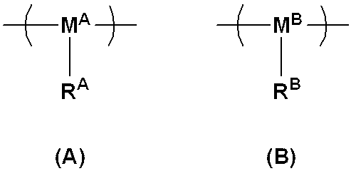
- the polymer preferably includes polyimide, polyester, polyurea containing the side chain, or a repeating unit represented by the following formula (A) and a repeating unit represented by the following formula (B).
- R A is at least one selected from groups represented by formulas (1) to (6)
- R B is at least selected from groups represented by formulas (21) to (35).
- 1 type, M A and M B each independently represent a group derived from a polymerizable group.
- the main chain is derived from a radical polymerizable monomer such as (meth) acrylic acid, itaconic acid, fumaric acid, maleic acid, ⁇ -methylene- ⁇ -butyrolactone, ethylene, styrene, maleimide, norbornene, or a polysiloxane structure. Is preferred.
- the group derived from the polymerizable group is preferably at least one selected from the group represented by the following formula.
- R C represents a hydrogen atom, an alkyl group having 1 to 3 carbon atoms, a carboxyl group or a carboxylmethyl group
- R D represents a single bond, —C ( ⁇ O) —O—, —C ( ⁇ O ) —NH— or a phenylene group
- R E represents a hydroxy group, an alkyl or alkoxy group having 1 to 10 carbon atoms, or a phenyl group
- a broken line represents a bond with R A or R B.
- the polymerizable group is preferably derived from (meth) acrylic acid, ⁇ -methylene- ⁇ -butyrolactone, styrene, maleimide, and (meth) acrylic acid, ⁇ -methylene- ⁇ -butyrolactone, styrene More preferably, those derived from (meth) acrylic acid and ⁇ -methylene- ⁇ -butyrolactone are even more preferred.
- the content of the photosensitive side chain is preferably 5 mol% or more, more preferably 10 mol% or more in all side chains. Further, the content of the liquid crystalline side chain is preferably 95 mol% or less, more preferably 90 mol% or less in all side chains.
- the total content of the photosensitive side chain and the liquid crystalline side chain is preferably 70 mol% or more, more preferably 80 mol% or more in all side chains.
- the liquid crystalline polymer preferably contains a polar group in at least one of the photosensitive side chain and the liquid crystalline side chain.
- a polar group a hydroxy group, a carboxyl group, an amide group and an amino group are preferable, and a carboxyl group is more preferable.
- the liquid crystalline polymer may contain a crosslinked structure to the extent that liquid crystallinity is not impaired. Examples of the crosslinked structure include those derived from an oxirane ring-containing group such as a glycidyl group, an oxetane ring-containing group, and the like.
- the liquid crystalline polymer may contain other side chains other than the photosensitive side chain and the liquid crystalline side chain as long as the effects of the present invention are not impaired.
- Examples of such a side chain include linear or branched alkyl groups having 1 to 15 carbon atoms, linear or branched halogenated alkyl groups having 1 to 15 carbon atoms, and aryl groups having 6 to 20 carbon atoms.
- the content of other side chains is preferably 30 mol% or less in all side chains.
- alkyl group examples include methyl group, ethyl group, n-propyl group, isopropyl group, n-butyl group, isobutyl group, sec-butyl group, tert-butyl group, n-pentyl group, n-hexyl group, n- Examples include heptyl group, n-octyl group, n-nonyl group, n-decyl group, n-undecyl group, n-dodecyl group, n-tridecyl group, n-tetradecyl group, n-pentadecyl group and the like.
- halogenated alkyl group examples include groups in which some or all of the hydrogen atoms of these alkyl groups have been substituted with halogen atoms such as fluorine, chlorine, bromine and iodine atoms.
- aryl group examples include a phenyl group, 1-naphthyl group, 2-naphthyl group, 1-anthryl group, 2-anthryl group, 9-anthryl group, 1-phenanthryl group, 2-phenanthryl group, 3-phenanthryl group, 4 -Phenanthryl group, 9-phenanthryl group and the like.
- heteroaryl group those containing an oxygen atom, a nitrogen atom, a sulfur atom, a selenium atom and the like are preferable.
- aralkyl group examples include a benzyl group, a phenethyl group, a naphthylmethyl group, and a naphthylethyl group.
- the heteroaralkyl group preferably includes an oxygen atom, a nitrogen atom, a sulfur atom, a selenium atom, and the like, and specifically includes a thienylmethyl group, a furanylmethyl group, an oxazolylmethyl group, and 3-isoxazolylmethyl group.
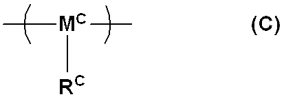
- repeating unit having such a side chain those represented by the following formula (C) are preferable.
- R C represents a linear or branched alkyl group having 1 to 15 carbon atoms, a linear or branched halogenated alkyl group having 1 to 15 carbon atoms, an aryl group having 6 to 20 carbon atoms, It represents a heteroaryl group having 2 to 20 carbon atoms, an aralkyl group having 7 to 20 carbon atoms, a heteroaralkyl group having 3 to 20 carbon atoms, an oxirane ring-containing group such as a glycidyl group, an oxetane ring-containing group, and the like.
- M C represents a group derived from a polymerizable group.
- the polymerizable group include the same ones as mentioned in the description of M A and M B.
- the weight average molecular weight (Mw) of the polymer is preferably 2,000 to 1,000,000, considering the strength of the resulting coating film, the workability during coating film formation, and the uniformity of the coating film, and is preferably 5,000. More preferable is 100,000.
- Mw is a measured value in terms of polystyrene by gel permeation chromatography (GPC).
- the polymer can be synthesized, for example, according to the method described in International Publication No. 2014/054785.
- the method for producing the retardation film of the present invention includes: [I] A step of applying a composition for forming a retardation film containing a resin component containing the liquid crystalline polymer and an organic solvent to a substrate to form a coating film having a thickness of more than 300 nm and not more than 50,000 nm, [II] a step of irradiating the coating film with polarized ultraviolet rays, and [III] a step of heating the film irradiated with the polarized ultraviolet rays to obtain a film having a thickness of more than 300 nm and not more than 50,000 nm.
- the base material is not particularly limited, but a plastic substrate such as a glass substrate, an acetate substrate, an acrylic substrate, a polycarbonate substrate, a polyethylene terephthalate substrate, a polyethylene naphthalate substrate, a cycloolefin polymer substrate, or a polyimide substrate. Etc. can be used.
- the retardation film forming composition includes a resin component containing the liquid crystalline polymer and an organic solvent.
- the composition for forming a retardation film is preferably a solution in which the polymer is dissolved in an organic solvent from the viewpoint that it is suitable for forming a retardation film.
- the resin component may be all the liquid crystalline polymer, but may contain other polymers (hereinafter referred to as other polymers) as long as the liquid crystal developing ability and the photosensitive performance are not impaired.
- other polymers include poly (meth) acrylate, polyamic acid, polyimide, and the like.
- the content of the other polymer in the resin component is preferably 0.5 to 80% by mass, and more preferably 1 to 50% by mass.
- the content of the resin component is preferably 1 to 20% by mass, more preferably 3 to 15% by mass, and even more preferably 3 to 10% by mass.
- organic solvent examples include N, N-dimethylformamide, N, N-dimethylacetamide, N-methyl-2-pyrrolidone, N-methylcaprolactam, 2-pyrrolidone, N-ethylpyrrolidone, N-vinylpyrrolidone, dimethyl sulfoxide, Tetramethylurea, pyridine, dimethylsulfone, hexamethylsulfoxide, ⁇ -butyrolactone, 3-methoxy-N, N-dimethylpropanamide, 3-ethoxy-N, N-dimethylpropanamide, 3-butoxy-N, N-dimethyl Propanamide, 1,3-dimethyl-imidazolidinone, ethyl amyl ketone, methyl nonyl ketone, methyl ethyl ketone, methyl isoamyl ketone, methyl isopropyl ketone, cyclohexanone, ethylene carbonate, propylene carbonate, dig
- a poor solvent may be added in order to improve the film thickness uniformity and the surface smoothness.
- the poor solvent include isopropyl alcohol, methoxymethylpentanol, methyl cellosolve, ethyl cellosolve, butyl cellosolve, methyl cellosolve acetate, ethyl cellosolve acetate, diisobutyl carbinol, butyl carbitol, ethyl carbitol, ethyl carbitol acetate, ethylene glycol, Ethylene glycol monoacetate, ethylene glycol monoisopropyl ether, ethylene glycol monobutyl ether, propylene glycol, propylene glycol monoacetate, propylene glycol monomethyl ether, propylene glycol monobutyl ether, propylene glycol-tert-butyl ether, dipropylene glycol monomethyl ether, dipropylene glycol The Chill ether, diethylene glycol,
- the content of the poor solvent is preferably 5 to 80% by mass, more preferably 20 to 60% by mass in the total solvent so as not to significantly reduce the solubility of the entire solvent.
- the said poor solvent may be used individually by 1 type, and may mix and use 2 or more types.
- the retardation film forming composition contains a surfactant such as a fluorine-based surfactant, a silicone-based surfactant, or a nonionic surfactant. May be included.
- a surfactant such as a fluorine-based surfactant, a silicone-based surfactant, or a nonionic surfactant. May be included.
- the surfactant examples include Ftop (registered trademark) 301, EF303, EF352 (manufactured by Mitsubishi Materials Electronic Chemicals Co., Ltd.), MegaFuck (registered trademark) F171, F173, R-30 (manufactured by DIC Corporation), Fluorad (registered trademark) FC430, FC431 (manufactured by 3M), Asahi Guard (registered trademark) AG710 (manufactured by Asahi Glass Co., Ltd.), Surflon (registered trademark) S-382, SC101, SC102, SC103, SC104, SC105, SC106 ( AGC Seimi Chemical Co., Ltd.).
- the content of the surfactant is preferably 0.01 to 2 parts by mass, and more preferably 0.01 to 1 part by mass with respect to 100 parts by mass of the resin component.
- the retardation film forming composition may contain a functional silane-containing compound.
- the functional silane-containing compound include 3-aminopropyltrimethoxysilane, 3-aminopropyltriethoxysilane, 2-aminopropyltrimethoxysilane, 2-aminopropyltriethoxysilane, N- (2-aminoethyl)- 3-aminopropyltrimethoxysilane, N- (2-aminoethyl) -3-aminopropylmethyldimethoxysilane, 3-ureidopropyltrimethoxysilane, 3-ureidopropyltrimethoxysilane, 3-ureidopropyltriethoxysilane, N-ethoxycarbonyl-3-aminopropyl Trimethoxysilane, N-ethoxycarbonyl-3-aminopropyltriethoxysilane, N-triethoxysilylpropyl
- the content of the functional silane-containing compound is preferably 0.1 to 30 parts by mass and more preferably 1 to 20 parts by mass with respect to 100 parts by mass of the resin component. If it is the said range, the adhesive improvement effect will be acquired.
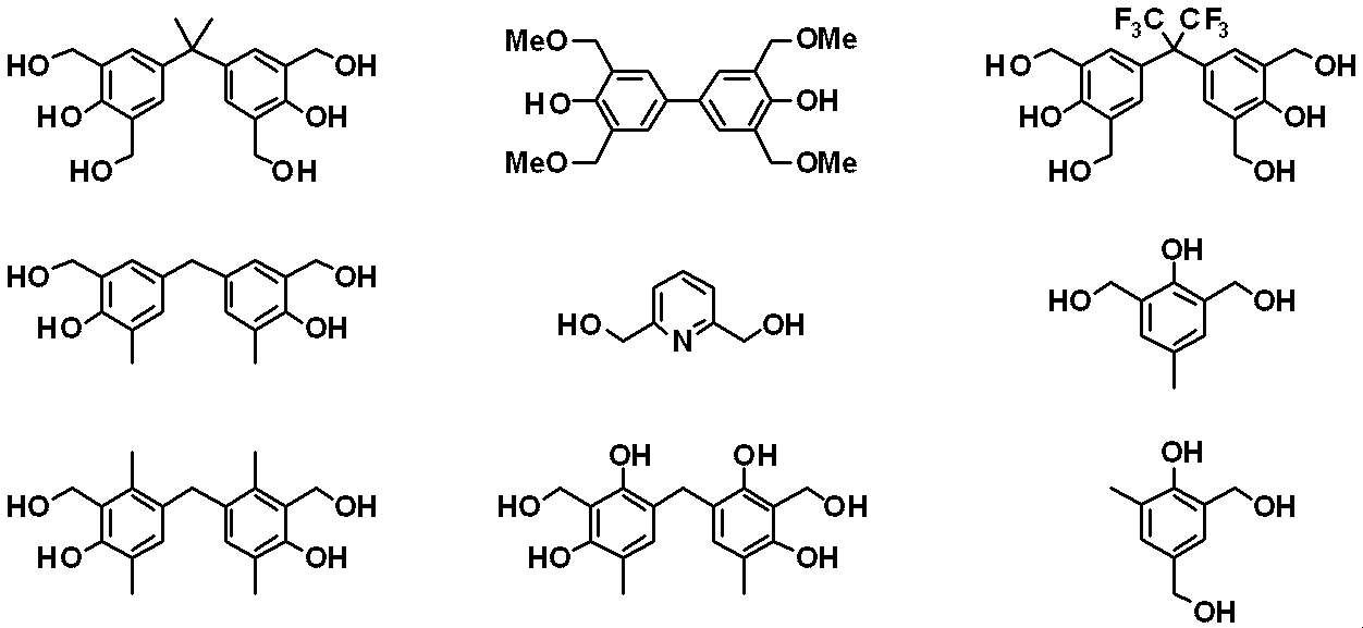
- the composition for forming a retardation film further includes additives such as a phenoplast compound, an epoxy group-containing compound, and an oxetane ring-containing compound for the purpose of improving reliability, suppressing barrier properties and reduction in retardation. May be included.
- phenoplast compound examples include, but are not limited to, those shown below.
- epoxy group-containing compound examples include ethylene glycol diglycidyl ether, polyethylene glycol diglycidyl ether, propylene glycol diglycidyl ether, tripropylene glycol diglycidyl ether, polypropylene glycol diglycidyl ether, neopentyl glycol diglycidyl ether, and 1,6- Hexanediol diglycidyl ether, glycerin diglycidyl ether, 2,2-dibromoneopentyl glycol diglycidyl ether, 1,3,5,6-tetraglycidyl-2,4-hexanediol, N, N, N ′, N ′ -Tetraglycidyl-m-xylenediamine, 1,3-bis (N, N-diglycidylaminomethyl) cyclohexane, N, N, N ', N'-tetraglycidyl-4,4'-diaminodip
- the retardation film forming composition may further contain a photosensitizer.
- a photosensitizer a colorless sensitizer and a triplet sensitizer are preferable.
- the photosensitizer include aromatic nitro compounds, coumarin (7-diethylamino-4-methylcoumarin, 7-hydroxy4-methylcoumarin), ketocoumarin, carbonyl biscoumarin, and aromatic 2-hydroxyketone (2-hydroxybenzophenone).
- aromatic 2-hydroxy ketone (benzophenone), coumarin, ketocoumarin, carbonyl biscoumarin, acetophenone, anthraquinone, xanthone, thioxanthone, and acetophenone ketal are preferred.
- the content of the additive or photosensitizer is preferably 0.1 to 30 parts by mass, and more preferably 0.5 to 20 parts by mass with respect to 100 parts by mass of the resin component. If it is the said range, sufficient effect will be acquired and liquid crystallinity will not be impaired.
- a dielectric material, a conductive material, and further a crosslinkable compound may be added to the retardation film forming composition as long as the effects of the present invention are not impaired.
- the method for applying the retardation film forming composition to a substrate is not particularly limited.
- industrially, screen printing, gravure printing, offset printing, flexographic printing, inkjet method, and the like are common.
- Other coating methods include a dipping method, a die coating method, a roll coating method, a slit coating method, a spin coating method, a spray coating method, and the like, and these may be used depending on the purpose.
- the retardation film forming composition After the retardation film forming composition is applied on the substrate, it is preferably 50 to 200 ° C., more preferably 50 to 150 ° C., by a heating means such as a hot plate, a heat circulation oven, or an infrared oven. A solvent can be evaporated and a coating film can be obtained. The temperature at this time is preferably lower than the liquid crystal phase expression temperature of the polymer.
- the thickness of the coating film is more than 300 nm and not more than 50,000 nm, but the lower limit is preferably 350 nm, more preferably 400 nm, even more preferably 1,000 nm, and most preferably 1. 500 nm.
- the upper limit is preferably 20,000 nm, more preferably 10,000 nm, even more preferably 6,000 nm, and most preferably 5,000 nm.
- step [II] when irradiating the surface of the coating film with polarized ultraviolet rays, the substrate is irradiated with polarized ultraviolet rays from a certain direction through a polarizing plate.
- the ultraviolet rays to be used those having a wavelength in the range of 100 to 400 nm are suitable. The optimum wavelength is selected through a filter or the like depending on the type of coating film used. For example, ultraviolet rays having a wavelength in the range of 290 to 400 nm can be selected and used so that the photocrosslinking reaction can be selectively induced.
- the ultraviolet light for example, light emitted from a high-pressure mercury lamp can be used.
- the irradiation amount of polarized ultraviolet rays depends on the coating film used.
- the amount of irradiation of the polarized ultraviolet light that achieves the maximum value of ⁇ A (hereinafter also referred to as ⁇ Amax) that is the difference between the ultraviolet light absorbance in the direction parallel to the polarization direction of the polarized ultraviolet light and the ultraviolet light absorbance in the direction perpendicular to the polarization direction of the polarized ultraviolet light.
- the amount is preferably in the range of 1 to 70%, more preferably in the range of 1 to 50%.
- step [III] by heating the coating film irradiated with polarized ultraviolet rays, a large anisotropy (phase difference) can be imparted to the coating film.
- Heating can be performed using a heating means such as a hot plate, a heat circulation type oven, or an infrared type oven.
- the heating temperature can be determined in consideration of the temperature at which the liquid crystallinity of the coating film used is developed.
- the heating temperature is preferably within the range of the temperature at which the liquid crystalline polymer exhibits liquid crystallinity (hereinafter referred to as liquid crystal expression temperature).
- the liquid crystal expression temperature on the coating film surface is expected to be lower than the liquid crystal expression temperature when a photosensitive side chain polymer that can exhibit liquid crystallinity is observed in bulk.
- the heating temperature is more preferably within the temperature range of the liquid crystal expression temperature on the coating film surface. That is, the temperature range of the heating temperature after irradiation with polarized ultraviolet rays is 10 ° C. lower than the lower limit of the temperature range of the liquid crystal expression temperature of the chain polymer to be used, and 10 ° C.
- the temperature of the range is the temperature of the range made into an upper limit. If the heating temperature is lower than the above temperature range, the anisotropic amplification effect due to heat in the coating film tends to be insufficient, and if the heating temperature is too higher than the above temperature range, the state of the coating film Tends to be close to an isotropic liquid state (isotropic phase), and in this case, self-organization may make it difficult to reorient in one direction.
- the liquid crystal expression temperature is an isotropic phase in which the liquid crystalline polymer has a temperature higher than the glass transition temperature at which a phase transition occurs from the solid phase to the liquid crystal phase and causes a phase transition from the liquid crystal phase to the isotropic phase (isotropic phase). The temperature below the transition temperature.
- the thickness of the coating film formed after heating is more than 300 nm and not more than 50,000 nm, but the lower limit thereof is preferably 350 nm, more preferably 400 nm, and still more preferably 1,000 nm. Most preferably, it is 1,500 nm.
- the upper limit is preferably 20,000 nm, more preferably 10,000 nm, even more preferably 6,000 nm, and most preferably 5,000 nm.
- the introduction of the anisotropy to the coating film can be realized with high efficiency by the manufacturing method. That is, a phase difference appears. And a base material with a phase difference film can be manufactured with high efficiency.
- the retardation film of the present invention thus obtained also has a water vapor barrier property. It is considered that the barrier property is improved because the mesogen skeleton is oriented finely to obtain a ⁇ -conjugate and ⁇ - ⁇ stacking effect.
- the water vapor transmission rate when the thickness of the retardation film is 1,000 nm is preferably 500 g / m 2 ⁇ day or less.
- the water vapor transmission rate is a value measured under the conditions of a temperature of 40 ° C. and a relative humidity of 90% according to JIS Z 0208 “Method of testing moisture permeability of moisture-proof packaging material (cup method)”.
- the retardation film having a water vapor barrier property of the present invention is particularly useful as a retardation film for an organic EL display. Since the organic EL display provided with the retardation film of the present invention has a high water vapor barrier property, the organic EL display is excellent in reliability and can produce a high-definition display with a large screen.
- the number average molecular weight (Mn) and the weight average molecular weight (Mw) were measured using Shodex® GPC-101 (solvent: tetrahydrofuran, calibration curve: standard polystyrene) manufactured by Showa Denko K.K.
- the obtained reaction solution was added dropwise to 300 mL of methanol, and the resulting precipitate was filtered, washed with methanol, and dried under reduced pressure to obtain a powdered polymer P1 (yield 12.67 g, yield 80%).
- Retardation film forming composition C1 is spin-coated on an 80 ⁇ m thick acetate film (made by HOLBEIN ART MATERIALS) as a substrate, dried on a hot plate at 70 ° C. for 3 minutes, and a polymer having a thickness of 1,000 nm A layer was formed. Next, after irradiating the film surface with ultraviolet rays of 313 nm through a polarizing plate at 10 mJ / cm 2 , the film was heated on a 140 ° C. hot plate for 10 minutes to form a film F1 with a water vapor barrier retardation film having a thickness of 1,000 nm. Produced.
- the water vapor barrier property was evaluated by the following method according to various conditions of JIS Z 0208 “Method of moisture permeability test for moisture-proof packaging materials (cup method)”. Using a regular hexagonal coated film with a moisture permeable area of 28.27 cm 2 , about 20 g of calcium chloride as a hygroscopic agent is sealed in a screw-tightened moisture permeable cup, and weighing operation at intervals of 1 hour or more is repeated. The water vapor transmission rate was calculated from the mass increase. The results are shown in Table 1.
- Example 1-2 In the same manner as in Example 1-1, except that the retardation film forming composition C2 was used instead of the retardation film forming composition C1, and the ultraviolet ray irradiation at 313 nm was changed to 4 mJ / cm 2 , the water vapor barrier property A film F2-1 with a retardation film was produced and its water vapor barrier property was evaluated. The results are shown in Table 1.
- Example 1-3 In the same manner as in Example 1-1, except that the retardation film forming composition C2 was used instead of the retardation film forming composition C1, and the ultraviolet irradiation at 313 nm was changed to 7 mJ / cm 2 , the water vapor barrier property A film with a retardation film F2-2 was prepared and its water vapor barrier property was evaluated. The results are shown in Table 1.
- Example 1-4 A film with water vapor barrier retardation film F2-3 was prepared in the same manner as in Example 1-1 except that the retardation film forming composition C2 was used instead of the retardation film forming composition C1. The water vapor barrier property was evaluated. The results are shown in Table 1.
- Example 1-5 Water vapor barrier properties were the same as in Example 1-1 except that the retardation film forming composition C3 was used instead of the retardation film forming composition C1, and the ultraviolet irradiation at 313 nm was changed to 100 mJ / cm 2 . A film F3 with a retardation film was produced, and the water vapor barrier property was evaluated. The results are shown in Table 1.
- Example 1-6 In the same manner as in Example 1-1, except that the retardation film forming composition C4 was used instead of the retardation film forming composition C1, and the ultraviolet ray irradiation at 313 nm was changed to 100 mJ / cm 2 , the water vapor barrier property A film F4 with a retardation film was produced, and the water vapor barrier property was evaluated. The results are shown in Table 1.
- Example 1-1 A film F1 ′ was produced in the same manner as in Example 1-1 except that ultraviolet irradiation was not performed, and the water vapor barrier property was evaluated. The results are shown in Table 1.
- Example 1-2 A film F2 ′ was produced in the same manner as in Example 1-4 except that no ultraviolet irradiation was performed, and the water vapor barrier property was evaluated. The results are shown in Table 1.
- Example 1-3 A film F3 ′ was produced in the same manner as in Example 1-5 except that no ultraviolet irradiation was performed, and the water vapor barrier property was evaluated. The results are shown in Table 1.
- Example 1-4 A film F4 ′ was produced in the same manner as in Example 1-6 except that ultraviolet irradiation was not performed, and the water vapor barrier property was evaluated. The results are shown in Table 1.
- phase difference film forming composition C1 is spin-coated on a glass substrate on which an ITO film is formed with a length of 40 mm, a width of 30 mm, and a thickness of 0.7 mm, dried on a hot plate at 70 ° C. for 3 minutes, A polymer layer of 000 nm was formed. Next, after irradiating the surface of the coating film with ultraviolet rays of 313 nm at 10 mJ / cm 2 via a polarizing plate, it was heated on a hot plate at 140 ° C. for 10 minutes to obtain a glass substrate G1 with a retardation film having a thickness of 1,000 nm. .
- the phase difference value was evaluated using the Mueller matrix polarimeter (Axometrics make, product name Axoscan).
- the measurement wavelength was 550 nm and the measurement temperature was 23 ° C.
- the results are shown in Table 2.
- Example 2-2 The retardation film was prepared in the same manner as in Example 2-1, except that the retardation film forming composition C2 was used instead of the retardation film forming composition C1, and the ultraviolet irradiation at 313 nm was changed to 4 mJ / cm 2.
- the attached glass substrate G2-1 was produced, and the retardation value was evaluated. The results are shown in Table 2.
- Example 2-3 The retardation film was prepared in the same manner as in Example 2-1, except that the retardation film forming composition C2 was used instead of the retardation film forming composition C1, and the ultraviolet irradiation at 313 nm was changed to 7 mJ / cm 2.
- the attached glass substrate G2-2 was prepared, and the retardation value was evaluated. The results are shown in Table 2.
- Example 2-4 A glass substrate G2-3 with a retardation film was prepared in the same manner as in Example 2-1, except that the retardation film forming composition C2 was used instead of the retardation film forming composition C1, The phase difference value was evaluated. The results are shown in Table 2.
- Example 2-5 The retardation film was prepared in the same manner as in Example 2-1, except that the retardation film forming composition C3 was used instead of the retardation film forming composition C1, and the ultraviolet irradiation at 313 nm was changed to 100 mJ / cm 2. The attached glass substrate G3 was produced, and the retardation value was evaluated. The results are shown in Table 2.
- Example 2-6 The retardation film was prepared in the same manner as in Example 1-1 except that the retardation film forming composition C4 was used instead of the retardation film forming composition C1 and the ultraviolet irradiation at 313 nm was changed to 100 mJ / cm 2. The attached glass substrate G4 was produced and the retardation value was evaluated. The results are shown in Table 2.
- Example 2-1 A glass substrate G1 ′ with a retardation film was produced in the same manner as in Example 2-1 except that no ultraviolet irradiation was performed, and the retardation value was evaluated. The results are shown in Table 2.
- Example 2-2 A glass substrate G2 ′ with a retardation film was produced in the same manner as in Example 2-4 except that ultraviolet irradiation was not performed, and the retardation value was evaluated. The results are shown in Table 2.
- Example 2-3 A glass substrate G3 ′ with a retardation film was produced in the same manner as in Example 2-5 except that ultraviolet irradiation was not performed, and the retardation value was evaluated. The results are shown in Table 2.
- Example 2-4 A glass substrate G4 ′ with a retardation film was produced in the same manner as in Example 2-6 except that ultraviolet irradiation was not performed, and the retardation value was evaluated. The results are shown in Table 2.
- the retardation film of the present invention has excellent water vapor barrier properties and can function as a retardation film.
Landscapes
- Physics & Mathematics (AREA)
- Chemical & Material Sciences (AREA)
- General Physics & Mathematics (AREA)
- Optics & Photonics (AREA)
- Polymers & Plastics (AREA)
- Organic Chemistry (AREA)
- Health & Medical Sciences (AREA)
- Medicinal Chemistry (AREA)
- Chemical Kinetics & Catalysis (AREA)
- Engineering & Computer Science (AREA)
- Theoretical Computer Science (AREA)
- Crystallography & Structural Chemistry (AREA)
- Polarising Elements (AREA)
- Electroluminescent Light Sources (AREA)
- Liquid Crystal (AREA)
- Addition Polymer Or Copolymer, Post-Treatments, Or Chemical Modifications (AREA)
- Manufacture Of Macromolecular Shaped Articles (AREA)
Abstract
Description
1.感光性側鎖を有する液晶性ポリマーを含み、膜厚が300nmを超え50,000nm以下である、水蒸気バリア性を有する位相差膜。
2.前記感光性側鎖が、光架橋、光異性化又は光フリース転移を起こすものである1の位相差膜。
3.前記感光性側鎖が、下記式(1)~(6)で表される基から選ばれる少なくとも1種である2の位相差膜。
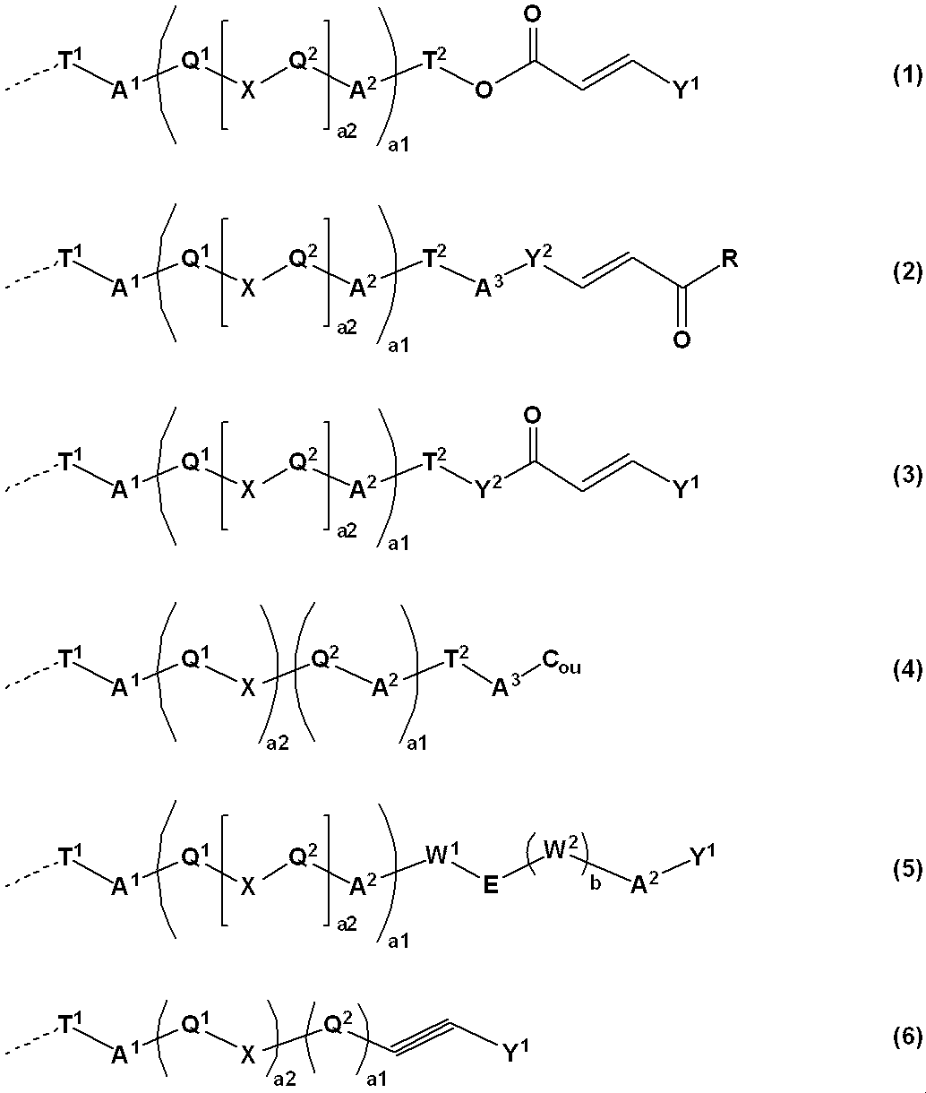
T1は、ハロゲン原子で置換されていてもよい炭素数1~12のアルキレン基を表し;
T2は、単結合、又はハロゲン原子で置換されていてもよい炭素数1~12のアルキレン基を表し;
Y1は、フェニル基、ナフチル基、ビフェニリル基、フラニル基及びピロリル基から選ばれる1価の芳香族基、炭素数5~8の1価の環状脂肪族炭化水素基、又はこれらの置換基から選ばれる2~6の基が連結基A2を介して結合してなる基を表し、これらに結合する水素原子の一部が-COOR0(R0は、水素原子又は炭素数1~5のアルキル基を表す。)、-NO2、-CN、-CH=C(CN)2、-CH=CH-CN、ハロゲン原子、炭素数1~5のアルキル基又は炭素数1~5のアルコキシ基で置換されてもよく;
Y2は、フェニレン基、ナフタレンジイル基、ビフェニリレン基、フランジイル基及びピロールジイル基から選ばれる2価の芳香族基、炭素数5~8の2価の環状脂肪族炭化水素基、又はこれらの置換基から選ばれる2~6の基が連結基A2を介して結合してなる基を表し、これらに結合する水素原子の一部が-NO2、-CN、-CH=C(CN)2、-CH=CH-CN、ハロゲン原子、炭素数1~5のアルキル基又は炭素数1~5のアルコキシ基で置換されてもよく;
Rは、ヒドロキシ基若しくは炭素数1~6のアルコキシ基、又はY1と同じ定義を表し;
Xは、単結合、-C(=O)-O-、-O-C(=O)-、-N=N-、-CH=CH-、-C≡C-、-CH=CH-C(=O)-O-又は-O-C(=O)-CH=CH-を表し、Xの数が2以上であるときは、各Xは同一でも異なっていてもよく;
Couは、クマリン-6-イル基又はクマリン-7-イル基を表し、これらに結合する水素原子の一部が-NO2、-CN、-CH=C(CN)2、-CH=CH-CN、ハロゲン原子、炭素数1~5のアルキル基又は炭素数1~5のアルコキシ基で置換されてもよく;
Q1及びQ2は、それぞれ独立に、フェニレン基、ナフタレンジイル基、ビフェニリレン基、フランジイル基及びピロールジイル基から選ばれる2価の芳香族基、炭素数5~8の2価の環状脂肪族炭化水素基、又はこれらの置換基から選ばれる2~6の基が連結基A2を介して結合してなる基を表すが、Xが、-CH=CH-CO-O-又は-O-CO-CH=CH-である場合、-CH=CH-が結合する側のQ1又はQ2は2価の芳香族基であり、Q1の数が2以上のときは、各Q1は同一でも異なっていてもよく、Q2の数が2以上のときは、各Q2は同一でも異なっていてもよく;
Eは、-C(=O)-O-又は-O-C(=O)-を表し;
W1及びW2は、それぞれ独立に、フェニレン基、ナフタレンジイル基、ビフェニリレン基、フランジイル基、ピロールジイル基、又はこれらの置換基から選ばれる2~6の基が連結基A2を介して結合してなる基を表し;
a1は、0又は1を表し;
a2は、0~2の整数を表し;
a1とa2がともに0であって、T2が単結合であるときは、A1は単結合を表し;
a1が1であって、T2が単結合であるときは、A2は単結合を表し;
bは、0又は1を表し;
破線は、主鎖との結合手を表す。)
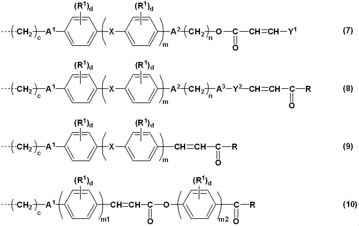
4.前記感光性側鎖が、下記式(7)~(10)で表される基から選ばれる3の位相差膜。

R1は、-NO2、-CN、ハロゲン原子、炭素数1~5のアルキル基、又は炭素数1~5のアルコキシ基を表し;
cは、1~12の整数を表し;
mは、0~2の整数を表し;
m1及びm2は、それぞれ独立に、1~3の整数を表し;
dは、0~4の整数を表し;
nは、0~12の整数を表す。)
5.前記感光性側鎖が、下記式(11)~(13)で表される基から選ばれる3の位相差膜。

6.前記感光性側鎖が、下記式(14)又は(15)で表される基である3の位相差膜。
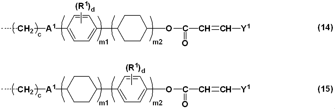
7.前記感光性側鎖が、下記式(16)又は(17)で表される基である3の位相差膜。

8.前記感光性側鎖が、下記式(18)又は(19)で表される基である3の位相差膜。

9.前記感光性側鎖が、下記式(20)で表される基である3の位相差膜。

10.前記液晶性ポリマーが、更に、下記式(21)~(35)で表される基から選ばれる少なくとも1種の液晶性側鎖を含む1~9のいずれかの位相差膜。

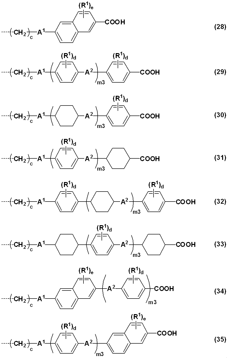
R2は、水素原子、-NO2、-CN、-CH=C(CN)2、-CH=CH-CN、ハロゲン原子、フェニル基、ナフチル基、ビフェニリル基、フラニル基、1価の窒素含有複素環含有基、炭素数5~8の環状脂肪族炭化水素基、炭素数1~12のアルキル基、又は炭素数1~12のアルコキシ基を表し;
Y3は、フェニル基、ナフチル基、ビフェニリル基、フラニル基、1価の窒素含有複素環含有基、炭素数5~8の環状脂肪族炭化水素基、又はこれらの置換基から選ばれる2~6の基が連結基A2を介して結合してなる基を表し、これらに結合する水素原子の一部が-NO2、-CN、ハロゲン原子、炭素数1~5のアルキル基、又は炭素数1~5のアルコキシ基で置換されてもよく;
Z1及びZ2は、それぞれ独立に、単結合、-C(=O)-、-CH2O-、-CH=N-又は-CF2-を表し;
hは、0~5の整数を表し;
kは、それぞれ独立に、0~2の整数を表すが、式(25)及び(26)において、全てのkの合計は2以上であり、
m3は、1~3の整数を表す。)
11.前記液晶性ポリマーが、下記式(A)で表される繰り返し単位及び下記式(B)で表される繰り返し単位を含むものである10の位相差膜。

12.前記重合性基に由来する基が、下記式で表される基から選ばれる少なくとも1種である11の位相差膜。

13.前記液晶性ポリマーが液晶性を発現する温度範囲が、50~300℃である1~12のいずれかの位相差膜。
14.1~13のいずれかの位相差膜を備える有機ELスディスプレイ。
15.感光性側鎖を有する液晶性ポリマーを含む樹脂成分と有機溶媒とを含む位相差膜形成用組成物を基材に塗布して、膜厚が300nmを超え50,000nm以下の塗膜を形成する工程、
前記塗膜に偏光紫外線を照射する工程、及び
前記偏光紫外線を照射した膜を加熱し、膜厚が300nmを超え50,000nm以下の膜を得る工程
を含む水蒸気バリア性を有する位相差膜の製造方法。
16.前記感光性側鎖が、光架橋、光異性化又は光フリース転移を起こすものである15の位相差膜の製造方法。
17.前記感光性側鎖が、前記式(1)~(6)で表される基から選ばれる少なくとも1種である16の位相差膜の製造方法。
18.前記液晶性ポリマーが、更に、前記式(21)~(35)で表される基から選ばれる少なくとも1種の液晶性側鎖を含む14~17のいずれかの位相差膜の製造方法。
19.前記液晶性ポリマーが液晶性を発現する温度範囲が、50~300℃である14~18のいずれかの位相差膜の製造方法。
本発明の水蒸気バリア性を有する位相差膜は、感光性側鎖を有する液晶性ポリマーを含み、膜厚が300nmを超え50,000nm以下である。






本発明の位相差膜の製造方法は、
[I]前記液晶性ポリマーを含む樹脂成分と有機溶媒とを含む位相差膜形成用組成物を基材に塗布して、膜厚が300nmを超え50,000nm以下の塗膜を形成する工程、
[II]前記塗膜に偏光紫外線を照射する工程、及び
[III]前記偏光紫外線を照射した膜を加熱し、膜厚が300nmを超え50,000nm以下の膜を得る工程
を含むものである。
[合成例1-1]モノマーMA1の合成
国際公開第2011/084546号に記載された方法に従って、下記式で表されるモノマーMA1を合成した。

特開平9-118717号公報に記載された方法に従って、下記式で表されるモノマーMA2を合成した。

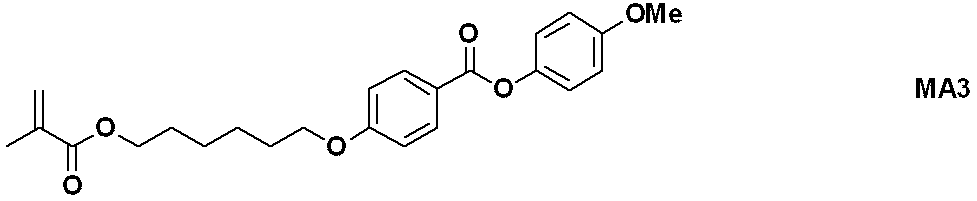
Macromolecules (2012), 45(21), pp. 8547-8554に記載された方法に従って、下記式で表されるモノマーMA3を合成した。
国際公開第2013/133078号に記載された方法に従って、下記式で表されるモノマーMA4を合成した。

国際公開第2013/133078号に記載された方法に従って、下記式で表されるモノマーMA5を合成した。

[合成例2-1]ポリマーP1の合成
モノマーMA1 6.64g及びモノマーMA2 9.19gをテトラヒドロフラン(THF)146.42gに溶解し、ダイアフラムポンプで脱気を行った後、2,2'-アゾビスイソブチロニトリル(AIBN)0.82gを加え、再び脱気を行った。この後、60℃で8時間反応させた。得られた反応溶液をメタノール300mLに滴下し、得られた沈殿物をろ過、メタノール洗浄洗浄、及び減圧乾燥し、粉末状のポリマーP1を得た(収量12.67g、収率80%)。ポリマーP1の組成比は、モノマーMA1:モノマーMA2=40:60であった。また、ポリマーP1のMnは16,000、Mw/Mnは1.75であった。
原料として、モノマーMA1 1.66g及びモノマーMA3 2.06gを用いた以外は、実施例1と同様の方法で粉末状のポリマーP2を得た。ポリマーP2の組成比は、モノマーMA1:モノマーMA3=50:50であった。また、ポリマーP2のMnは27,000、Mw/Mnは2.25であった。
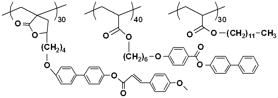
冷却管を備えたフラスコに、モノマーMA4 2.16g(4.8mmol)、モノマーMA5 1.80g(3.6mmol)、n-ドデシルアクリレート0.84g(3.6mmol)、N-メチル-2-ピロリドン(NMP)48.0g、及びAIBN0.10gを仕込み、フラスコ内を窒素置換した後、60℃で20時間攪拌して反応させた。得られた反応溶液を400mLのメタノールに投入し、白色粉末を沈殿させた。この白色粉末をろ過した後、室温で真空乾燥を行い、下記式で表されるポリマーP3を得た(収量3.60g、収率75%)。ポリマーP3のMnは13,258、Mw/Mnは2.0であった。
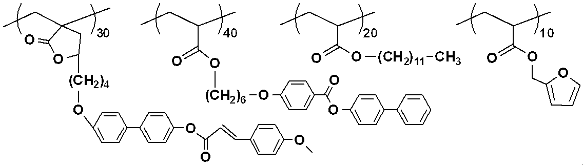
冷却管を備えたフラスコに、モノマーMA4 1.80g(4mmol)、モノマーMA5 1.50g(3mmol)、n-ドデシルアクリレート 0.48g(2mmol)、フルフリルメタクリレート(東京化成工業(株))0.17g(1mmol)、NMP40.0g、及びAIBN 0.085gを仕込み、フラスコ内を窒素置換した後、60℃で20時間撹拌して反応させた。得られた反応溶液を400mLのメタノールに投入し、白色粉末を沈殿させた。この白色粉末をろ過した後、室温で真空乾燥を行い、下記式で表されるポリマーP4を得た(収量2.80g、収率71%)。ポリマーP4のMnは12,000、Mw/Mnは2.00であった。
[調製例1]位相差膜形成用組成物C1の調製
NMP7.5gに、ポリマーP1 1.5gを加え、室温で1時間攪拌して溶解させた。この溶液に、ブチルセロソルブ(BC)1.0gを加え、攪拌し、位相差膜形成用組成物C1を得た。
プロピレングリコールモノメチルエーテル(PGME)3.2gに、ポリマーP2 1.0gを加え、室温で1時間攪拌して溶解させた。この溶液に、シクロヘキサノン(CHN)1.4gを加え、攪拌し、位相差膜形成用組成物C2を得た。
トルエン5.0gに、ポリマーP3 1.0gを加え、室温で1時間攪拌して溶解させた。この溶液に、CHN2.3gを加え、攪拌し、位相差膜形成用組成物C3を得た。
トルエン5.0gに、ポリマーP4 1.0gを加え、室温で1時間攪拌して溶解させた。この溶液に、CHN2.3gを加え、攪拌し、位相差膜形成用組成物C4を得た。
[実施例1-1]
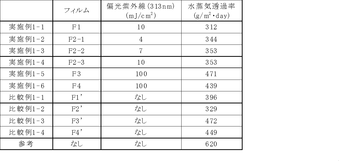
位相差膜形成用組成物C1を、基材である厚さ80μmのアセテートフィルム(HOLBEIN ART MATERIALS社製)にスピンコートし、70℃のホットプレートで3分間乾燥し、膜厚1,000nmのポリマー層を形成した。次いで、塗膜面に偏光板を介して313nmの紫外線を10mJ/cm2照射した後に、140℃のホットプレートで10分間加熱し、膜厚1,000nmの水蒸気バリア性位相差膜付きフィルムF1を作製した。
得られた水蒸気バリア性位相差膜付きフィルムを用いて、JIS Z 0208「防湿包装材料の透湿度試験方法(カップ法)」の諸条件に準じ、次の手法で水蒸気バリア性を評価した。
透湿面積28.27cm2である正六角形型の塗膜フィルムを用い、ネジ絞めタイプの透湿カップに吸湿剤として塩化カルシウム約20gを封入し、1時間以上間隔の秤量操作を繰り返し、カップの質量増加から水蒸気透過率を算出した。結果を表1に示す。
水蒸気透過率[g/m2・day]=(m/s)/t
m:一定秤量間隔における増加質量(g)
s:透湿面積(m2)
t:一定量間隔時間(h)/24(h)
位相差膜形成用組成物C1のかわりに位相差膜形成用組成物C2を用い、313nmの紫外線照射を4mJ/cm2とした以外は、実施例1-1と同様の方法で、水蒸気バリア性位相差膜付きフィルムF2-1を作製し、水蒸気バリア性を評価した。結果を表1に示す。
位相差膜形成用組成物C1のかわりに位相差膜形成用組成物C2を用い、313nmの紫外線照射を7mJ/cm2とした以外は、実施例1-1と同様の方法で、水蒸気バリア性位相差膜付きフィルムF2-2を作製し、水蒸気バリア性を評価した。結果を表1に示す。
位相差膜形成用組成物C1のかわりに位相差膜形成用組成物C2を用いた以外は、実施例1-1と同様の方法で、水蒸気バリア性位相差膜付きフィルムF2-3を作製し、水蒸気バリア性を評価した。結果を表1に示す。
位相差膜形成用組成物C1のかわりに位相差膜形成用組成物C3を用い、313nmの紫外線照射を100mJ/cm2とした以外は、実施例1-1と同様の方法で、水蒸気バリア性位相差膜付きフィルムF3を作製し、水蒸気バリア性を評価した。結果を表1に示す。
位相差膜形成用組成物C1のかわりに位相差膜形成用組成物C4を用い、313nmの紫外線照射を100mJ/cm2とした以外は、実施例1-1と同様の方法で、水蒸気バリア性位相差膜付きフィルムF4を作製し、水蒸気バリア性を評価した。結果を表1に示す。
紫外線の照射を行わなかった以外は、実施例1-1と同様の方法で、フィルムF1'を作製し、水蒸気バリア性を評価した。結果を表1に示す。
紫外線の照射を行わなかった以外は、実施例1-4と同様の方法で、フィルムF2'を作製し、水蒸気バリア性を評価した。結果を表1に示す。
紫外線の照射を行わなかった以外は、実施例1-5と同様の方法で、フィルムF3'を作製し、水蒸気バリア性を評価した。結果を表1に示す。
紫外線の照射を行わなかった以外は、実施例1-6と同様の方法で、フィルムF4'を作製し、水蒸気バリア性を評価した。結果を表1に示す。
[実施例2-1]
位相差膜形成用組成物C1を、縦40mm×横30mm×厚さ0.7mmでITO膜が形成されたガラス基板にスピンコートし、70℃のホットプレートで3分間乾燥し、膜厚1,000nmのポリマー層を形成した。次いで、塗膜面に偏光板を介して313nmの紫外線を10mJ/cm2照射した後に、140℃のホットプレートで10分間加熱し、膜厚1,000nmの位相差膜付きガラス基板G1を得た。
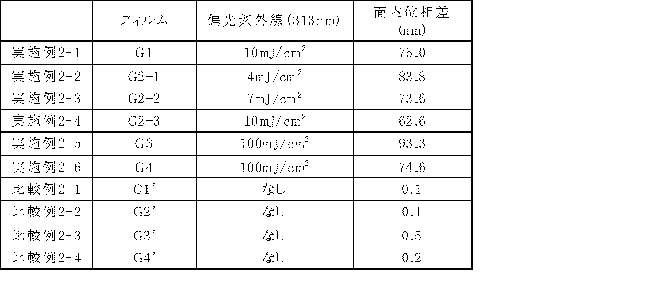
得られた位相差膜付きガラス基板について、ミュラーマトリクス・ポラリメーター(Axometrics社製、製品名Axoscan)を用いて位相差値を評価した。なお、測定波長は550nm、測定温度は23℃であった。結果を表2に示す。
位相差膜形成用組成物C1のかわりに位相差膜形成用組成物C2を用い、313nmの紫外線照射を4mJ/cm2とした以外は、実施例2-1と同様の方法で、位相差膜付きガラス基板G2-1を作製し、位相差値を評価した。結果を表2に示す。
位相差膜形成用組成物C1のかわりに位相差膜形成用組成物C2を用い、313nmの紫外線照射を7mJ/cm2とした以外は、実施例2-1と同様の方法で、位相差膜付きガラス基板G2-2を作製し、位相差値を評価した。結果を表2に示す。
位相差膜形成用組成物C1のかわりに位相差膜形成用組成物C2を用いた以外は、実施例2-1と同様の方法で、位相差膜付きガラス基板G2-3を作製し、位相差値を評価した。結果を表2に示す。
位相差膜形成用組成物C1のかわりに位相差膜形成用組成物C3を用い、313nmの紫外線照射を100mJ/cm2とした以外は、実施例2-1と同様の方法で、位相差膜付きガラス基板G3を作製し、位相差値を評価した。結果を表2に示す。
位相差膜形成用組成物C1のかわりに位相差膜形成用組成物C4を用い、313nmの紫外線照射を100mJ/cm2とした以外は、実施例1-1と同様の方法で、位相差膜付きガラス基板G4を作製し、位相差値を評価した。結果を表2に示す。
紫外線の照射を行わなかった以外は、実施例2-1と同様の方法で、位相差膜付きガラス基板G1'を作製し、位相差値を評価した。結果を表2に示す。
紫外線の照射を行わなかった以外は、実施例2-4と同様の方法で、位相差膜付きガラス基板G2'を作製し、位相差値を評価した。結果を表2に示す。
紫外線の照射を行わなかった以外は、実施例2-5と同様の方法で、位相差膜付きガラス基板G3'を作製し、位相差値を評価した。結果を表2に示す。
紫外線の照射を行わなかった以外は、実施例2-6と同様の方法で、位相差膜付きガラス基板G4'を作製し、位相差値を評価した。結果を表2に示す。
Claims (19)
- 感光性側鎖を有する液晶性ポリマーを含み、膜厚が300nmを超え50,000nm以下である、水蒸気バリア性を有する位相差膜。
- 前記感光性側鎖が、光架橋、光異性化又は光フリース転移を起こすものである請求項1記載の位相差膜。
- 前記感光性側鎖が、下記式(1)~(6)で表される基から選ばれる少なくとも1種である請求項2記載の位相差膜。

T1は、ハロゲン原子で置換されていてもよい炭素数1~12のアルキレン基を表し;
T2は、単結合、又はハロゲン原子で置換されていてもよい炭素数1~12のアルキレン基を表し;
Y1は、フェニル基、ナフチル基、ビフェニリル基、フラニル基及びピロリル基から選ばれる1価の芳香族基、炭素数5~8の1価の環状脂肪族炭化水素基、又はこれらの置換基から選ばれる2~6の基が連結基A2を介して結合してなる基を表し、これらに結合する水素原子の一部が-COOR0(R0は、水素原子又は炭素数1~5のアルキル基を表す。)、-NO2、-CN、-CH=C(CN)2、-CH=CH-CN、ハロゲン原子、炭素数1~5のアルキル基又は炭素数1~5のアルコキシ基で置換されてもよく;
Y2は、フェニレン基、ナフタレンジイル基、ビフェニリレン基、フランジイル基及びピロールジイル基から選ばれる2価の芳香族基、炭素数5~8の2価の環状脂肪族炭化水素基、又はこれらの置換基から選ばれる2~6の基が連結基A2を介して結合してなる基を表し、これらに結合する水素原子の一部が-NO2、-CN、-CH=C(CN)2、-CH=CH-CN、ハロゲン原子、炭素数1~5のアルキル基又は炭素数1~5のアルコキシ基で置換されてもよく;
Rは、ヒドロキシ基若しくは炭素数1~6のアルコキシ基、又はY1と同じ定義を表し;
Xは、単結合、-C(=O)-O-、-O-C(=O)-、-N=N-、-CH=CH-、-C≡C-、-CH=CH-C(=O)-O-又は-O-C(=O)-CH=CH-を表し、Xの数が2以上であるときは、各Xは同一でも異なっていてもよく;
Couは、クマリン-6-イル基又はクマリン-7-イル基を表し、これらに結合する水素原子の一部が-NO2、-CN、-CH=C(CN)2、-CH=CH-CN、ハロゲン原子、炭素数1~5のアルキル基又は炭素数1~5のアルコキシ基で置換されてもよく;
Q1及びQ2は、それぞれ独立に、フェニレン基、ナフタレンジイル基、ビフェニリレン基、フランジイル基及びピロールジイル基から選ばれる2価の芳香族基、炭素数5~8の2価の環状脂肪族炭化水素基、又はこれらの置換基から選ばれる2~6の基が連結基A2を介して結合してなる基を表すが、Xが、-CH=CH-CO-O-又は-O-CO-CH=CH-である場合、-CH=CH-が結合する側のQ1又はQ2は2価の芳香族基であり、Q1の数が2以上のときは、各Q1は同一でも異なっていてもよく、Q2の数が2以上のときは、各Q2は同一でも異なっていてもよく;
Eは、-C(=O)-O-又は-O-C(=O)-を表し;
W1及びW2は、それぞれ独立に、フェニレン基、ナフタレンジイル基、ビフェニリレン基、フランジイル基、ピロールジイル基、又はこれらの置換基から選ばれる2~6の基が連結基A2を介して結合してなる基を表し;
a1は、0又は1を表し;
a2は、0~2の整数を表し;
a1とa2がともに0であって、T2が単結合であるときは、A1は単結合を表し;
a1が1であって、T2が単結合であるときは、A2は単結合を表し;
bは、0又は1を表し;
破線は、主鎖との結合手を表す。) - 前記感光性側鎖が、下記式(7)~(10)で表される基から選ばれる請求項3記載の位相差膜。
R1は、-NO2、-CN、ハロゲン原子、炭素数1~5のアルキル基、又は炭素数1~5のアルコキシ基を表し;
cは、1~12の整数を表し;
mは、0~2の整数を表し;
m1及びm2は、それぞれ独立に、1~3の整数を表し;
dは、0~4の整数を表し;
nは、0~12の整数を表す。) - 前記感光性側鎖が、下記式(11)~(13)で表される基から選ばれる請求項3記載の位相差膜。

R1は、-NO2、-CN、ハロゲン原子、炭素数1~5のアルキル基、又は炭素数1~5のアルコキシ基を表し;
cは、1~12の整数を表し;
dは、0~4の整数を表し;
eは、0~6の整数を表し;
mは、0~2の整数を表し;
m1は、1~3の整数を表す。) - 前記感光性側鎖が、下記式(14)又は(15)で表される基である請求項3記載の位相差膜。

R1は、-NO2、-CN、ハロゲン原子、炭素数1~5のアルキル基、又は炭素数1~5のアルコキシ基を表し;
cは、1~12の整数を表し、
dは、0~4の整数を表し;
m1及びm2は、それぞれ独立に、1~3の整数を表す。) - 前記感光性側鎖が、下記式(16)又は(17)で表される基である請求項3記載の位相差膜。
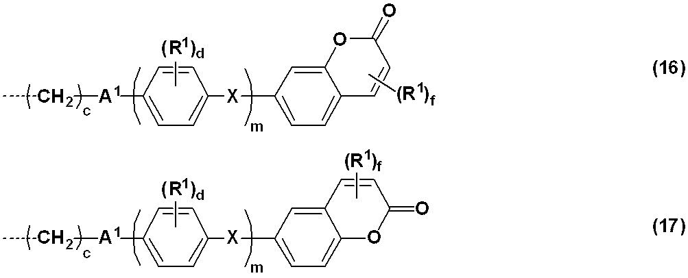
R1は、-NO2、-CN、ハロゲン原子、炭素数1~5のアルキル基、又は炭素数1~5のアルコキシ基を表し;
dは、0~4の整数を表し;
fは、0~5の整数を表し;
cは、1~12の整数を表し;
mは、0~2の整数を表す。) - 前記感光性側鎖が、下記式(18)又は(19)で表される基である請求項3記載の位相差膜。

R1は、-NO2、-CN、ハロゲン原子、炭素数1~5のアルキル基、又は炭素数1~5のアルコキシ基を表し;
cは、1~12の整数を表し;
dは、0~4の整数を表し;
gは、0~5の整数を表し;
m1及びm2は、それぞれ独立に、1~3の整数を表す。) - 前記感光性側鎖が、下記式(20)で表される基である請求項3記載の位相差膜。

R1は、-NO2、-CN、ハロゲン原子、炭素数1~5のアルキル基、又は炭素数1~5のアルコキシ基を表し;
cは1~12の整数を表し;
dは、0~4の整数を表し;
mは、0~2の整数を表す。) - 前記液晶性ポリマーが、更に、下記式(21)~(35)で表される基から選ばれる少なくとも1種の液晶性側鎖を含む請求項1~9のいずれか1項記載の位相差膜。
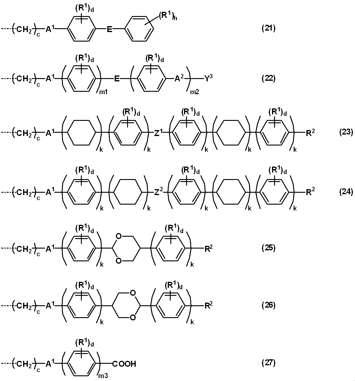
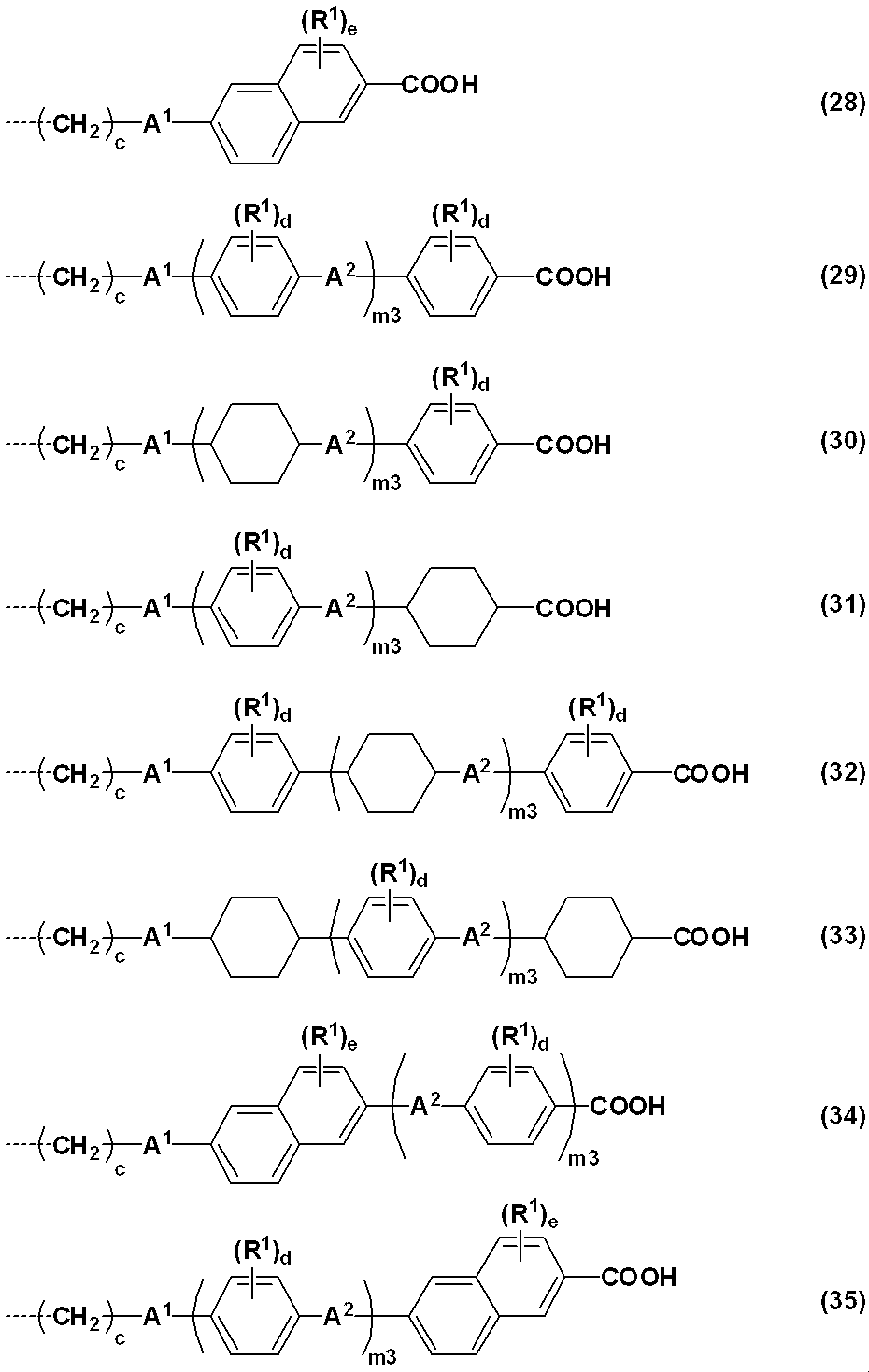
Eは、-C(=O)-O-又は-O-C(=O)-を表し;
R1は、-NO2、-CN、ハロゲン原子、炭素数1~5のアルキル基、又は炭素数1~5のアルコキシ基を表し;
R2は、水素原子、-NO2、-CN、-CH=C(CN)2、-CH=CH-CN、ハロゲン原子、フェニル基、ナフチル基、ビフェニリル基、フラニル基、1価の窒素含有複素環含有基、炭素数5~8の環状脂肪族炭化水素基、炭素数1~12のアルキル基、又は炭素数1~12のアルコキシ基を表し;
Y3は、フェニル基、ナフチル基、ビフェニリル基、フラニル基、1価の窒素含有複素環含有基、炭素数5~8の環状脂肪族炭化水素基、又はこれらの置換基から選ばれる2~6の基が連結基A2を介して結合してなる基を表し、これらに結合する水素原子の一部が-NO2、-CN、ハロゲン原子、炭素数1~5のアルキル基、又は炭素数1~5のアルコキシ基で置換されてもよく;
Z1及びZ2は、それぞれ独立に、単結合、-C(=O)-、-CH2O-、-CH=N-又は-CF2-を表し;
cは、1~12の整数を表し;
dは、0~4の整数を表し;
eは、0~6の整数を表し;
hは、0~5の整数を表し;
kは、それぞれ独立に、0~2の整数を表すが、式(25)及び(26)において、全てのkの合計は2以上であり;
m1及びm2は、それぞれ独立に、1~3の整数を表し;
m3は、1~3の整数を表す。) - 前記液晶性ポリマーが、下記式(A)で表される繰り返し単位及び下記式(B)で表される繰り返し単位を含むものである請求項10記載の位相差膜。

- 前記重合性基に由来する基が、下記式で表される基から選ばれる少なくとも1種である請求項11記載の位相差膜。

- 前記液晶性ポリマーが液晶性を発現する温度範囲が、50~300℃である請求項1~12のいずれか1項記載の位相差膜。
- 請求項1~13のいずれか1項記載の位相差膜を備える有機エレクトロルミネッセンスディスプレイ。
- 感光性側鎖を有する液晶性ポリマーを含む樹脂成分と有機溶媒とを含む位相差膜形成用組成物を基材に塗布して、膜厚が300nmを超え50,000nm以下の塗膜を形成する工程、
前記塗膜に偏光紫外線を照射する工程、及び
前記偏光紫外線を照射した膜を加熱し、膜厚が300nmを超え50,000nm以下の膜を得る工程
を含む水蒸気バリア性を有する位相差膜の製造方法。 - 前記感光性側鎖が、光架橋、光異性化又は光フリース転移を起こすものである請求項15記載の位相差膜の製造方法。
- 前記感光性側鎖が、下記式(1)~(6)で表される基から選ばれる少なくとも1種である請求項16記載の位相差膜の製造方法。
T1は、ハロゲン原子で置換されていてもよい炭素数1~12のアルキレン基を表し;
T2は、単結合、又はハロゲン原子で置換されていてもよい炭素数1~12のアルキレン基を表し;
Y1は、フェニル基、ナフチル基、ビフェニリル基、フラニル基及びピロリル基から選ばれる1価の芳香族基、炭素数5~8の1価の環状脂肪族炭化水素基、又はこれらの置換基から選ばれる2~6の基が連結基A2を介して結合してなる基を表し、これらに結合する水素原子の一部が-COOR0(R0は、水素原子又は炭素数1~5のアルキル基を表す。)、-NO2、-CN、-CH=C(CN)2、-CH=CH-CN、ハロゲン原子、炭素数1~5のアルキル基又は炭素数1~5のアルコキシ基で置換されてもよく;
Y2は、フェニレン基、ナフタレンジイル基、ビフェニリレン基、フランジイル基及びピロールジイル基から選ばれる2価の芳香族基、炭素数5~8の2価の環状脂肪族炭化水素基、又はこれらの置換基から選ばれる2~6の基が連結基A2を介して結合してなる基を表し、これらに結合する水素原子の一部が-NO2、-CN、-CH=C(CN)2、-CH=CH-CN、ハロゲン原子、炭素数1~5のアルキル基又は炭素数1~5のアルコキシ基で置換されてもよく;
Rは、ヒドロキシ基若しくは炭素数1~6のアルコキシ基、又はY1と同じ定義を表し;
Xは、単結合、-C(=O)-O-、-O-C(=O)-、-N=N-、-CH=CH-、-C≡C-、-CH=CH-C(=O)-O-又は-O-C(=O)-CH=CH-を表し、Xの数が2以上であるときは、各Xは同一でも異なっていてもよく;
Couは、クマリン-6-イル基又はクマリン-7-イル基を表し、これらに結合する水素原子の一部が-NO2、-CN、-CH=C(CN)2、-CH=CH-CN、ハロゲン原子、炭素数1~5のアルキル基又は炭素数1~5のアルコキシ基で置換されてもよく;
Q1及びQ2は、それぞれ独立に、フェニレン基、ナフタレンジイル基、ビフェニリレン基、フランジイル基及びピロールジイル基から選ばれる2価の芳香族基、炭素数5~8の2価の環状脂肪族炭化水素基、又はこれらの置換基から選ばれる2~6の基が連結基A2を介して結合してなる基を表すが、Xが、-CH=CH-CO-O-又は-O-CO-CH=CH-である場合、-CH=CH-が結合する側のQ1又はQ2は2価の芳香族基であり、Q1の数が2以上のときは、各Q1は同一でも異なっていてもよく、Q2の数が2以上のときは、各Q2は同一でも異なっていてもよく;
Eは、-C(=O)-O-又は-O-C(=O)-を表し;
W1及びW2は、それぞれ独立に、フェニレン基、ナフタレンジイル基、ビフェニリレン基、フランジイル基、ピロールジイル基、又はこれらの置換基から選ばれる2~6の基が連結基A2を介して結合してなる基を表し;
a1は、0又は1を表し;
a2は、0~2の整数を表し;
a1とa2がともに0であって、T2が単結合であるときは、A1は単結合を表し;
a1が1であって、T2が単結合であるときは、A2は単結合を表し;
bは、0又は1を表し;
破線は、主鎖との結合手を表す。) - 前記液晶性ポリマーが、更に、下記式(21)~(35)で表される基から選ばれる少なくとも1種の液晶性側鎖を含む請求項14~17のいずれか1項記載の位相差膜の製造方法。
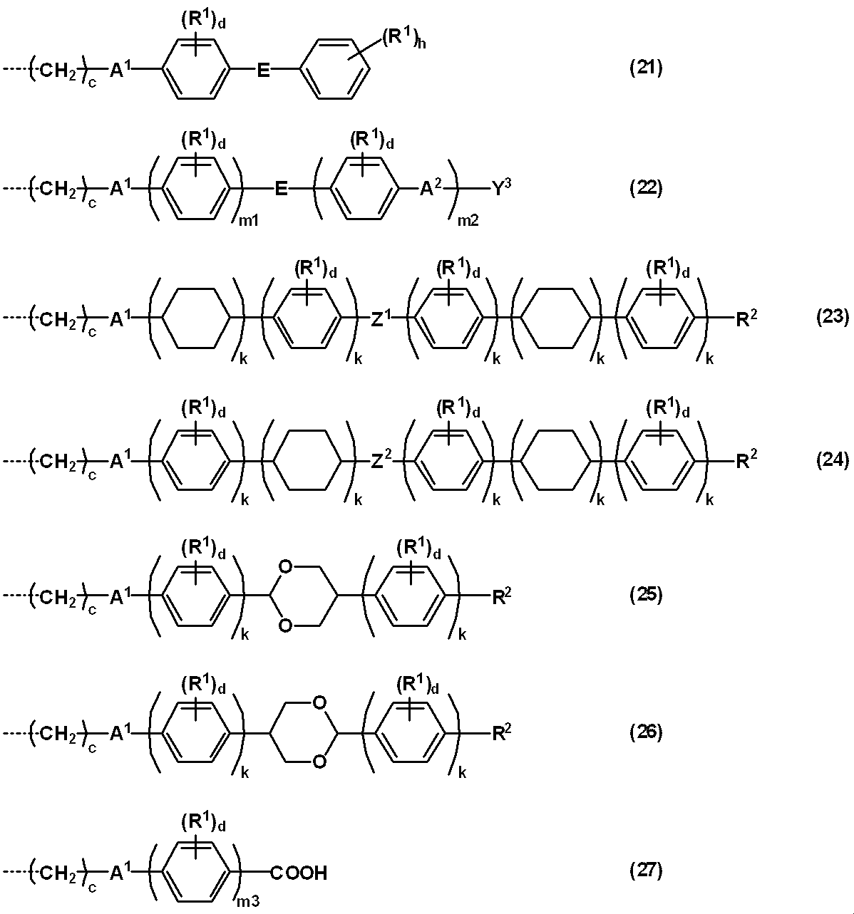

Eは、-C(=O)-O-又は-O-C(=O)-を表し;
R1は、-NO2、-CN、ハロゲン原子、炭素数1~5のアルキル基、又は炭素数1~5のアルコキシ基を表し;
R2は、水素原子、-NO2、-CN、-CH=C(CN)2、-CH=CH-CN、ハロゲン原子、フェニル基、ナフチル基、ビフェニリル基、フラニル基、1価の窒素含有複素環含有基、炭素数5~8の環状脂肪族炭化水素基、炭素数1~12のアルキル基、又は炭素数1~12のアルコキシ基を表し;
Y3は、フェニル基、ナフチル基、ビフェニリル基、フラニル基、1価の窒素含有複素環含有基、炭素数5~8の環状脂肪族炭化水素基、又はこれらの置換基から選ばれる2~6の基が連結基A2を介して結合してなる基を表し、これらに結合する水素原子の一部が-NO2、-CN、ハロゲン原子、炭素数1~5のアルキル基、又は炭素数1~5のアルコキシ基で置換されてもよく;
Z1及びZ2は、それぞれ独立に、単結合、-C(=O)-、-CH2O-、-CH=N-又は-CF2-を表し;
cは、1~12の整数を表し;
dは、0~4の整数を表し;
eは、0~6の整数を表し;
hは、0~5の整数を表し;
kは、それぞれ独立に、0~2の整数を表すが、式(25)及び(26)において、全てのkの合計は2以上であり;
m1及びm2は、それぞれ独立に、1~3の整数を表し;
m3は、1~3の整数を表す。) - 前記液晶性ポリマーが液晶性を発現する温度範囲が、50~300℃である請求項14~18のいずれか1項記載の位相差膜の製造方法。
Priority Applications (3)
| Application Number | Priority Date | Filing Date | Title |
|---|---|---|---|
| KR1020197008504A KR20190042065A (ko) | 2016-08-31 | 2017-08-30 | 수증기 배리어성을 갖는 위상차막 및 그 제조 방법 |
| CN201780067043.3A CN109923449B (zh) | 2016-08-31 | 2017-08-30 | 具有水蒸气阻隔性的相位差膜和其制造方法 |
| JP2018537327A JPWO2018043529A1 (ja) | 2016-08-31 | 2017-08-30 | 水蒸気バリア性を有する位相差膜及びその製造方法 |
Applications Claiming Priority (2)
| Application Number | Priority Date | Filing Date | Title |
|---|---|---|---|
| JP2016-168802 | 2016-08-31 | ||
| JP2016168802 | 2016-08-31 |
Publications (1)
| Publication Number | Publication Date |
|---|---|
| WO2018043529A1 true WO2018043529A1 (ja) | 2018-03-08 |
Family
ID=61301807
Family Applications (1)
| Application Number | Title | Priority Date | Filing Date |
|---|---|---|---|
| PCT/JP2017/031072 Ceased WO2018043529A1 (ja) | 2016-08-31 | 2017-08-30 | 水蒸気バリア性を有する位相差膜及びその製造方法 |
Country Status (5)
| Country | Link |
|---|---|
| JP (1) | JPWO2018043529A1 (ja) |
| KR (1) | KR20190042065A (ja) |
| CN (1) | CN109923449B (ja) |
| TW (1) | TWI759324B (ja) |
| WO (1) | WO2018043529A1 (ja) |
Cited By (2)
| Publication number | Priority date | Publication date | Assignee | Title |
|---|---|---|---|---|
| WO2022080378A1 (ja) * | 2020-10-13 | 2022-04-21 | 日産化学株式会社 | 単層位相差材の製造方法 |
| WO2024038887A1 (ja) * | 2022-08-18 | 2024-02-22 | 日産化学株式会社 | 重合体組成物及び単層位相差材 |
Families Citing this family (3)
| Publication number | Priority date | Publication date | Assignee | Title |
|---|---|---|---|---|
| JP7517327B2 (ja) * | 2019-03-29 | 2024-07-17 | 日産化学株式会社 | 重合体組成物及び単層位相差材 |
| KR102945879B1 (ko) * | 2019-03-29 | 2026-03-30 | 닛산 가가쿠 가부시키가이샤 | 중합체 조성물 및 단층 위상차재 |
| JP7580200B2 (ja) * | 2020-04-09 | 2024-11-11 | 住友化学株式会社 | 光学積層体 |
Citations (7)
| Publication number | Priority date | Publication date | Assignee | Title |
|---|---|---|---|---|
| JP2004231641A (ja) * | 2003-01-10 | 2004-08-19 | Fuji Photo Film Co Ltd | 化合物、位相差板、及び光学異方性層の形成方法 |
| JP2007148099A (ja) * | 2005-11-29 | 2007-06-14 | Nitto Denko Corp | ポジティブcプレートの製造方法及びポジティブcプレート、そのポジティブcプレートを用いた液晶パネル及び液晶表示装置 |
| JP2012189686A (ja) * | 2011-03-09 | 2012-10-04 | Fujifilm Corp | 3d表示装置及び時分割方式3d表示システム |
| WO2013133078A1 (ja) * | 2012-03-09 | 2013-09-12 | 日産化学工業株式会社 | 重合体、該重合体を含む組成物、及び単層塗布型水平配向フィルム |
| WO2014142103A1 (ja) * | 2013-03-15 | 2014-09-18 | 日産化学工業株式会社 | 組成物及び単層塗布型水平配向フィルム |
| JP2017016089A (ja) * | 2015-06-30 | 2017-01-19 | Jsr株式会社 | 視野角補償フィルム用重合体組成物、視野角補償フィルム、視野角補償フィルムの製造方法、偏光板、液晶表示素子及び有機el素子 |
| WO2017138509A1 (ja) * | 2016-02-10 | 2017-08-17 | 日産化学工業株式会社 | 液晶組成物、及び単層塗布型水平配向フィルム |
Family Cites Families (15)
| Publication number | Priority date | Publication date | Assignee | Title |
|---|---|---|---|---|
| AU2003218476A1 (en) * | 2002-05-31 | 2003-12-19 | Elsicon, Inc. | Hybrid polymer materials for liquid crystal alignment layers |
| JP2004083799A (ja) * | 2002-08-28 | 2004-03-18 | Fuji Photo Film Co Ltd | セルロースアシレートフィルム及びその製造方法、並びに該フィルムを用いた光学フィルム、液晶表示装置及びハロゲン化銀写真感光材料 |
| JP2007297606A (ja) * | 2006-03-31 | 2007-11-15 | Dainippon Printing Co Ltd | 紫外線硬化性組成物、位相差フィルム、および、位相差フィルムの製造方法 |
| JP5549174B2 (ja) * | 2009-10-13 | 2014-07-16 | Dic株式会社 | 重合性ナフタレン化合物 |
| JP4905532B2 (ja) * | 2009-10-23 | 2012-03-28 | 凸版印刷株式会社 | 液晶表示装置用カラーフィルタ基板及び液晶表示装置 |
| JP5898404B2 (ja) * | 2011-01-07 | 2016-04-06 | 大阪有機化学工業株式会社 | 光配向膜用及び光学異方性フィルム用組成物 |
| KR101933220B1 (ko) * | 2011-07-07 | 2018-12-27 | 스미또모 가가꾸 가부시키가이샤 | 편광 소자, 원편광판 및 이들의 제조 방법 |
| WO2013081066A1 (ja) * | 2011-11-29 | 2013-06-06 | 日産化学工業株式会社 | 液晶配向膜の製造方法、液晶配向膜及び液晶表示素子 |
| WO2013168739A1 (ja) | 2012-05-09 | 2013-11-14 | 三菱樹脂株式会社 | ガスバリア性フィルム及びその製造方法 |
| TWI636973B (zh) * | 2012-10-05 | 2018-10-01 | 日商日產化學工業股份有限公司 | 具有橫向電場驅動型液晶顯示元件用液晶配向膜之基板的製造方法 |
| WO2014077248A1 (ja) * | 2012-11-14 | 2014-05-22 | 日産化学工業株式会社 | 光反応性組成物、それを用いた光配向膜、及び光学異方性膜 |
| KR20170008274A (ko) * | 2014-05-23 | 2017-01-23 | 디아이씨 가부시끼가이샤 | 화상 표시 장치 및 그것에 사용하는 배향 재료 |
| JP6601605B2 (ja) * | 2014-12-04 | 2019-11-06 | 日産化学株式会社 | 液晶配向剤、液晶配向膜及び液晶表示素子 |
| WO2016114210A1 (ja) * | 2015-01-13 | 2016-07-21 | Dic株式会社 | 重合性液晶組成物及び該組成物を用いて作製した光学異方体、位相差膜、反射防止膜、液晶表示素子 |
| CN105219401B (zh) * | 2015-09-07 | 2017-12-08 | 江苏和成新材料有限公司 | 可聚合液晶混合物及其应用 |
-
2017
- 2017-08-30 KR KR1020197008504A patent/KR20190042065A/ko not_active Withdrawn
- 2017-08-30 WO PCT/JP2017/031072 patent/WO2018043529A1/ja not_active Ceased
- 2017-08-30 CN CN201780067043.3A patent/CN109923449B/zh active Active
- 2017-08-30 JP JP2018537327A patent/JPWO2018043529A1/ja active Pending
- 2017-08-31 TW TW106129728A patent/TWI759324B/zh active
Patent Citations (7)
| Publication number | Priority date | Publication date | Assignee | Title |
|---|---|---|---|---|
| JP2004231641A (ja) * | 2003-01-10 | 2004-08-19 | Fuji Photo Film Co Ltd | 化合物、位相差板、及び光学異方性層の形成方法 |
| JP2007148099A (ja) * | 2005-11-29 | 2007-06-14 | Nitto Denko Corp | ポジティブcプレートの製造方法及びポジティブcプレート、そのポジティブcプレートを用いた液晶パネル及び液晶表示装置 |
| JP2012189686A (ja) * | 2011-03-09 | 2012-10-04 | Fujifilm Corp | 3d表示装置及び時分割方式3d表示システム |
| WO2013133078A1 (ja) * | 2012-03-09 | 2013-09-12 | 日産化学工業株式会社 | 重合体、該重合体を含む組成物、及び単層塗布型水平配向フィルム |
| WO2014142103A1 (ja) * | 2013-03-15 | 2014-09-18 | 日産化学工業株式会社 | 組成物及び単層塗布型水平配向フィルム |
| JP2017016089A (ja) * | 2015-06-30 | 2017-01-19 | Jsr株式会社 | 視野角補償フィルム用重合体組成物、視野角補償フィルム、視野角補償フィルムの製造方法、偏光板、液晶表示素子及び有機el素子 |
| WO2017138509A1 (ja) * | 2016-02-10 | 2017-08-17 | 日産化学工業株式会社 | 液晶組成物、及び単層塗布型水平配向フィルム |
Cited By (2)
| Publication number | Priority date | Publication date | Assignee | Title |
|---|---|---|---|---|
| WO2022080378A1 (ja) * | 2020-10-13 | 2022-04-21 | 日産化学株式会社 | 単層位相差材の製造方法 |
| WO2024038887A1 (ja) * | 2022-08-18 | 2024-02-22 | 日産化学株式会社 | 重合体組成物及び単層位相差材 |
Also Published As
| Publication number | Publication date |
|---|---|
| TW201825537A (zh) | 2018-07-16 |
| JPWO2018043529A1 (ja) | 2019-06-24 |
| CN109923449B (zh) | 2021-12-21 |
| TWI759324B (zh) | 2022-04-01 |
| CN109923449A (zh) | 2019-06-21 |
| KR20190042065A (ko) | 2019-04-23 |
Similar Documents
| Publication | Publication Date | Title |
|---|---|---|
| TWI626266B (zh) | 具有橫向電場驅動型液晶顯示元件用液晶配向膜之基板的製造方法 | |
| KR102000322B1 (ko) | 폴리이미드 바니시의 조제 방법, 및 액정 배향제 | |
| CN109923449B (zh) | 具有水蒸气阻隔性的相位差膜和其制造方法 | |
| TWI665290B (zh) | 聚合物組成物及橫向電場驅動型液晶顯示元件用液晶配向膜 | |
| CN105190414B (zh) | 包含具有光反应性基团的交联性化合物的液晶取向剂 | |
| KR102280115B1 (ko) | 액정 배향제, 액정 배향막 및 액정 표시 소자 | |
| TW201809878A (zh) | 液晶定向劑、液晶定向膜及液晶顯示元件 | |
| KR102448661B1 (ko) | 횡전계 구동형 액정 표시 소자용 액정 배향막 제조용 조성물, 그 조성물을 사용한 액정 배향막 및 그 제조 방법, 그리고 액정 배향막을 갖는 액정 표시 소자 및 그 제조 방법 | |
| KR102540421B1 (ko) | 중합체 조성물, 액정 배향제, 액정 배향막, 그 액정 배향막을 갖는 기판 및 그 액정 배향막을 갖는 액정 표시 소자 | |
| TW202102557A (zh) | 聚合物組成物及單層相位差材 | |
| TWI888364B (zh) | 液晶配向劑、液晶配向膜及相位差材料 | |
| KR20210076925A (ko) | 액정 배향제, 액정 배향막 및 그것을 사용한 액정 표시 소자 | |
| CN103492462B (zh) | 组合物、液晶取向处理剂、液晶取向膜及液晶显示元件 | |
| TWI626269B (zh) | 具有橫向電場驅動型液晶顯示元件用液晶配向膜之基板之製造方法 | |
| TWI644931B (zh) | 具有橫向電場驅動型液晶顯示元件用液晶配向膜之基板之製造方法 | |
| JP6956948B2 (ja) | 液晶配向剤、液晶配向膜及び液晶表示素子 | |
| CN111886270B (zh) | 聚脲共聚物、液晶取向剂、液晶取向膜、及使用该液晶取向膜的液晶显示元件 | |
| TWI668491B (zh) | 具有橫向電場驅動型液晶顯示元件用液晶配向膜之基板之製造方法 | |
| JP6601605B2 (ja) | 液晶配向剤、液晶配向膜及び液晶表示素子 | |
| CN111868618B (zh) | 液晶取向剂、用于得到该液晶取向剂的聚合物、液晶取向膜、以及使用该液晶取向膜的液晶显示元件 | |
| CN111868617B (zh) | 液晶取向剂、用于得到该液晶取向剂的聚合物、液晶取向膜、以及使用其的液晶显示元件 | |
| WO2026053908A1 (ja) | 重合体組成物、位相差膜形成用組成物、配向膜形成用組成物及び位相差材 | |
| TW202104307A (zh) | 聚合物組成物及單層相位差材 |
Legal Events
| Date | Code | Title | Description |
|---|---|---|---|
| 121 | Ep: the epo has been informed by wipo that ep was designated in this application |
Ref document number: 17846533 Country of ref document: EP Kind code of ref document: A1 |
|
| ENP | Entry into the national phase |
Ref document number: 2018537327 Country of ref document: JP Kind code of ref document: A |
|
| NENP | Non-entry into the national phase |
Ref country code: DE |
|
| ENP | Entry into the national phase |
Ref document number: 20197008504 Country of ref document: KR Kind code of ref document: A |
|
| 122 | Ep: pct application non-entry in european phase |
Ref document number: 17846533 Country of ref document: EP Kind code of ref document: A1 |