WO2018042749A1 - ダイカスト用スリーブおよびその製造方法 - Google Patents
ダイカスト用スリーブおよびその製造方法 Download PDFInfo
- Publication number
- WO2018042749A1 WO2018042749A1 PCT/JP2017/015503 JP2017015503W WO2018042749A1 WO 2018042749 A1 WO2018042749 A1 WO 2018042749A1 JP 2017015503 W JP2017015503 W JP 2017015503W WO 2018042749 A1 WO2018042749 A1 WO 2018042749A1
- Authority
- WO
- WIPO (PCT)
- Prior art keywords
- less
- sleeve
- die casting
- molten metal
- supply port
- Prior art date
- Legal status (The legal status is an assumption and is not a legal conclusion. Google has not performed a legal analysis and makes no representation as to the accuracy of the status listed.)
- Ceased
Links
Images




Classifications
-
- B—PERFORMING OPERATIONS; TRANSPORTING
- B22—CASTING; POWDER METALLURGY
- B22D—CASTING OF METALS; CASTING OF OTHER SUBSTANCES BY THE SAME PROCESSES OR DEVICES
- B22D17/00—Pressure die casting or injection die casting, i.e. casting in which the metal is forced into a mould under high pressure
- B22D17/20—Accessories: Details
-
- B—PERFORMING OPERATIONS; TRANSPORTING
- B22—CASTING; POWDER METALLURGY
- B22D—CASTING OF METALS; CASTING OF OTHER SUBSTANCES BY THE SAME PROCESSES OR DEVICES
- B22D17/00—Pressure die casting or injection die casting, i.e. casting in which the metal is forced into a mould under high pressure
- B22D17/20—Accessories: Details
- B22D17/2015—Means for forcing the molten metal into the die
- B22D17/2023—Nozzles or shot sleeves
-
- C—CHEMISTRY; METALLURGY
- C21—METALLURGY OF IRON
- C21D—MODIFYING THE PHYSICAL STRUCTURE OF FERROUS METALS; GENERAL DEVICES FOR HEAT TREATMENT OF FERROUS OR NON-FERROUS METALS OR ALLOYS; MAKING METAL MALLEABLE, e.g. BY DECARBURISATION OR TEMPERING
- C21D1/00—General methods or devices for heat treatment, e.g. annealing, hardening, quenching or tempering
- C21D1/18—Hardening; Quenching with or without subsequent tempering
-
- C—CHEMISTRY; METALLURGY
- C21—METALLURGY OF IRON
- C21D—MODIFYING THE PHYSICAL STRUCTURE OF FERROUS METALS; GENERAL DEVICES FOR HEAT TREATMENT OF FERROUS OR NON-FERROUS METALS OR ALLOYS; MAKING METAL MALLEABLE, e.g. BY DECARBURISATION OR TEMPERING
- C21D9/00—Heat treatment, e.g. annealing, hardening, quenching or tempering, adapted for particular articles; Furnaces therefor
- C21D9/08—Heat treatment, e.g. annealing, hardening, quenching or tempering, adapted for particular articles; Furnaces therefor for tubular bodies or pipes
- C21D9/085—Cooling or quenching
-
- C—CHEMISTRY; METALLURGY
- C22—METALLURGY; FERROUS OR NON-FERROUS ALLOYS; TREATMENT OF ALLOYS OR NON-FERROUS METALS
- C22C—ALLOYS
- C22C38/00—Ferrous alloys, e.g. steel alloys
-
- C—CHEMISTRY; METALLURGY
- C22—METALLURGY; FERROUS OR NON-FERROUS ALLOYS; TREATMENT OF ALLOYS OR NON-FERROUS METALS
- C22C—ALLOYS
- C22C38/00—Ferrous alloys, e.g. steel alloys
- C22C38/02—Ferrous alloys, e.g. steel alloys containing silicon
-
- C—CHEMISTRY; METALLURGY
- C22—METALLURGY; FERROUS OR NON-FERROUS ALLOYS; TREATMENT OF ALLOYS OR NON-FERROUS METALS
- C22C—ALLOYS
- C22C38/00—Ferrous alloys, e.g. steel alloys
- C22C38/04—Ferrous alloys, e.g. steel alloys containing manganese
-
- C—CHEMISTRY; METALLURGY
- C22—METALLURGY; FERROUS OR NON-FERROUS ALLOYS; TREATMENT OF ALLOYS OR NON-FERROUS METALS
- C22C—ALLOYS
- C22C38/00—Ferrous alloys, e.g. steel alloys
- C22C38/18—Ferrous alloys, e.g. steel alloys containing chromium
- C22C38/22—Ferrous alloys, e.g. steel alloys containing chromium with molybdenum or tungsten
-
- C—CHEMISTRY; METALLURGY
- C22—METALLURGY; FERROUS OR NON-FERROUS ALLOYS; TREATMENT OF ALLOYS OR NON-FERROUS METALS
- C22C—ALLOYS
- C22C38/00—Ferrous alloys, e.g. steel alloys
- C22C38/18—Ferrous alloys, e.g. steel alloys containing chromium
- C22C38/24—Ferrous alloys, e.g. steel alloys containing chromium with vanadium
-
- C—CHEMISTRY; METALLURGY
- C22—METALLURGY; FERROUS OR NON-FERROUS ALLOYS; TREATMENT OF ALLOYS OR NON-FERROUS METALS
- C22C—ALLOYS
- C22C38/00—Ferrous alloys, e.g. steel alloys
- C22C38/18—Ferrous alloys, e.g. steel alloys containing chromium
- C22C38/26—Ferrous alloys, e.g. steel alloys containing chromium with niobium or tantalum
-
- C—CHEMISTRY; METALLURGY
- C22—METALLURGY; FERROUS OR NON-FERROUS ALLOYS; TREATMENT OF ALLOYS OR NON-FERROUS METALS
- C22C—ALLOYS
- C22C38/00—Ferrous alloys, e.g. steel alloys
- C22C38/18—Ferrous alloys, e.g. steel alloys containing chromium
- C22C38/30—Ferrous alloys, e.g. steel alloys containing chromium with cobalt
-
- C—CHEMISTRY; METALLURGY
- C22—METALLURGY; FERROUS OR NON-FERROUS ALLOYS; TREATMENT OF ALLOYS OR NON-FERROUS METALS
- C22C—ALLOYS
- C22C38/00—Ferrous alloys, e.g. steel alloys
- C22C38/18—Ferrous alloys, e.g. steel alloys containing chromium
- C22C38/36—Ferrous alloys, e.g. steel alloys containing chromium with more than 1.7% by weight of carbon
Definitions
- the present invention relates to a die casting sleeve, which is a component part of a die casting apparatus, and a manufacturing method thereof.
- a die casting sleeve which is one of the components of a die casting apparatus used for die casting, is generally cylindrical.
- a molten metal supply port for supplying the molten metal to the internal flow path is provided on the side surface of the cylindrical die casting sleeve.
- a molten metal such as aluminum, an aluminum alloy, zinc, or a zinc alloy is supplied into the cylinder from the molten metal supply port.
- the supplied molten metal is injected from the molten metal injection port toward the mold cavity by a plunger.
- SKD61 which is a standard steel type of “alloy tool steel” in JIS-G-4404: 2006, is often used as a material for such a die casting sleeve.
- a die casting sleeve in which a surface treatment such as a nitriding treatment is performed on the inner surface of a die casting sleeve made of SKD61 or the like (Patent Documents 1 and 2).
- melting loss refers to wear of the sleeve material caused by contact of the molten metal with the inner surface of the die casting sleeve. If the wear is severe, an abnormal injection occurs during casting, and the life of the die casting sleeve is shortened.
- surface treatment is performed on the inner surface of the sleeve for die casting, a certain degree of improvement in the corrosion resistance is recognized, but further improvement in the resistance to melting is required.
- An object of the present invention is to provide a die-casting sleeve excellent in melt resistance and a manufacturing method thereof.
- a die casting sleeve having a flow path therein A molten metal supply port for supplying a molten metal to the flow path from the outside penetrates from the inner surface of the die casting sleeve to the outer surface, Of the inner surface forming the flow path, at least a portion facing the melt supply port is in mass%, C: 0.4% or more, 2.5% or less, Si: 1.0% or less, Mn: 1.0% or less.
- a sleeve for die casting is provided, which is made of a material having a component composition of Cr: 3.0% to 12.0%, the balance Fe and impurities.
- a manufacturing method of a sleeve for die casting in which a molten metal supply port for supplying a molten metal from the outside to the flow path has an internal flow path and penetrates from the outer surface to the inner surface, Prepare a preliminary body to be the die casting sleeve, Of the inner surface forming the flow path, at least in a portion facing the molten metal supply port or a portion facing the molten metal supply port, C: 0.4% to 2.5%, Si: 1
- a die casting sleeve manufacturing method in which a material having a component composition of 0.0% or less, Mn: 1.0% or less, Cr: 3.0% or more and 12.0% or less, the balance Fe and impurities is provided.
- a sleeve for die casting excellent in melt resistance and a manufacturing method thereof are provided.
- the inventor investigated the state of melting damage occurring on the inner surface of the die casting sleeve. As a result, it has been found that the above-mentioned melting damage is remarkable in the inner surface of the die casting sleeve, particularly at a portion facing the molten metal supply port. Therefore, it has been found that the melt resistance of the entire die-casting sleeve can be improved by reviewing at least the material constituting this part, and the present invention has been completed.
- said "cylindrical shape” means the shape by which the cavity as a flow path was formed inside, such as cylindrical shape and a rectangular tube shape.
- the die casting sleeve may have a shape in which a cylindrical portion and a square tube portion are combined.
- the die casting sleeve may be provided with a protrusion, a flange, or the like on the outer peripheral surface of the cylindrical main body.
- the shape of the flow path may be a cylindrical shape, a prismatic shape, or a combination thereof.
- a cylindrical channel may be formed in the cylindrical die casting sleeve.
- a prismatic channel may be formed in a cylindrical die casting sleeve.
- the molten metal supply port is provided on the outer peripheral surface of the cylindrical die casting sleeve.
- the die casting sleeve is used in such a posture that the molten metal supply port opens upward and the flow path substantially extends in the horizontal direction.
- the melting damage includes “physical melting damage” caused by impact energy caused by dropping of the molten metal and “chemical melting damage” caused by a chemical reaction with the molten metal.
- physical melting damage greatly affects the resistance to melting at the portion of the inner surface that forms the flow channel that faces the molten metal supply port.
- the molten metal supplied from the molten metal supply port to the flow path hits “with momentum”, remarkable physical melting damage tends to occur.
- a die casting sleeve in which a surface treatment layer having a low chemical reactivity with the molten metal is provided on the material has been proposed.
- This surface treatment layer is provided for the purpose of preventing direct contact between the material forming the sleeve for die casting and the molten metal, and has a certain effect on chemical melting.
- there is a limit to the strength of the surface treatment layer with respect to physical melting caused by mechanical factors of the molten metal and only the surface treatment layer has a limited effect on suppressing physical melting.
- ADC12 Fe: 1.3 mass% or less
- aluminum alloy die casting of JIS-H-5302: 2006
- the temperature of the molten metal is 660-680 ° C.
- Some automobile parts are changed from iron to aluminum alloy for weight reduction. Such changes may compensate for die cast product strength that decreases with the change from iron to aluminum alloy.
- the present inventor reduced the physical melting loss in the portion facing the molten metal supply port on the inner surface forming the flow path, and reduced the chemical melting loss in the recent special die casting. I found that there was room for improvement.
- the inventor firstly made a material for a die casting sleeve that is resistant to physical impact when the molten metal is supplied and has low chemical reactivity with the molten metal (hereinafter simply referred to as “sleeve material”).
- sleeve material a material for a die casting sleeve that is resistant to physical impact when the molten metal is supplied and has low chemical reactivity with the molten metal.
- sleeve material “in mass%, C: 0.4% or more and 2.5% or less, Si: 1.0% or less, Mn: 1.0% or less, Cr: 3
- a raw material having a component composition of 0.0% or more and 12.0% or less, the balance Fe and impurities” is effective. The above component composition will be described below.
- C 0.4 mass% or more and 2.5 mass% or less (hereinafter, mass% is simply expressed as “%”)
- C is an element that combines with Cr, W, Mo, V, and Nb to form carbides and improves the wear resistance of the die casting sleeve. Improvement of wear resistance is effective in suppressing physical melting damage.
- the content is set to 0.4% or more and 2.5% or less.
- C is 0.4% or more and less than 1.0%. If the C content is within this range, the toughness and high temperature strength of the sleeve material can be easily achieved. More preferably, C is 0.9% or less.
- the sleeve material is preferably a sintered material obtained by sintering a powder material.
- the sintered material is preferably obtained by sintering metal powder having the same composition as that of the sleeve material to be obtained. In sintering, it is preferable to use HIP (hot isostatic pressing) treatment.
- C is 1.2% or more. More preferably, C is 1.5% or more. More preferably, C is 1.7% or more. More preferably, C is 2.3% or less.
- Si is normally used as a deoxidizer in a melt
- Mn is used as a deoxidizer like Si. And there exists an effect which improves hardenability and provides moderate quenching tempering hardness to the sleeve for die-casting. However, if too much, the retained austenite increases in the structure after quenching and tempering, and the toughness is lowered. Therefore, Mn is 1.0% or less. Preferably it is 0.7% or less. More preferably, it is 0.6% or less. Further, the lower limit of Mn is not particularly defined (it may be 0%), but it is preferably more than 0%. The amount of Mn is more preferably 0.1% or more. More preferably, it is 0.2% or more.
- Cr 3.0% or more and 12.0% or less
- Cr is an element effective for improving the wear resistance of the sleeve material by improving hardenability and forming carbide. Improvement of wear resistance is effective in suppressing physical melting damage.
- Cr has a melting point of about 1903 ° C., which is higher than the melting point of Fe (about 1539 ° C.), and is an element that makes it difficult to react with molten metal, so Cr is also effective in suppressing chemical erosion. Element.
- Cr is 3.0% or more and 12.0% or less.
- it is 3.5% or more. More preferably, it is 4.0% or more.
- it is preferably 11.0% or less.
- Cr when importance is attached to the erosion resistance, Cr is preferably 7.0% or more. More preferably, it is 8.0% or more, Most preferably, it is 9.0% or more. Moreover, when importance is attached to toughness, Cr is preferably less than 7.0%. More preferably, it is 6.0% or less, and particularly preferably 5.0% or less.
- the above-described sleeve material may contain one or more elements of Mo and W in addition to the above element types. It is preferable that Mo be less than 1.0% or 1.6% to 15.0% in the relational expression (Mo + 1 / 2W).
- Mo is specified as less than 1.0% is based on the assumption that Mo is contained as an impurity in the sleeve material, and Mo is not actively contained in the sleeve material. Mo itself is a relatively expensive material. In addition, when Mo is mixed in the material, the mechanical strength of the material increases, so that the workability difficulty of the material increases.
- a sleeve material having a Mo content of less than 1.0% in which Mo is not actively mixed is preferable because it can be provided at a relatively low cost and the degree of processing difficulty is not high.
- Mo is more preferably 0.5% or less, further preferably 0.3% or less, and still more preferably 0.15% or less.
- the lower limit of Mo can be 0%.
- Mo and W (Mo + 1 / 2W) in the relational expression 1.6% or more and 15.0% or less Mo and W combine with C to form carbides, and give wear resistance to the die casting sleeve. It is an element that suppresses physical erosion. Further, the melting point of Mo is about 2620 ° C., the melting point of W is about 3380 ° C., which is higher than the melting point of Fe, and Mo and W are effective elements for suppressing chemical melting. And it is an element which has a large secondary hardening action at the time of tempering and can impart high temperature strength. However, if it is too much, machinability and toughness are reduced. Mo and W can be contained alone or in combination as required.
- the content at this time can be specified together by “Mo equivalent” defined by the relational expression of (Mo + 1 / 2W) since W is an atomic weight approximately twice that of Mo.
- Mo equivalent defined by the relational expression of (Mo + 1 / 2W) since W is an atomic weight approximately twice that of Mo.
- it when containing at least one of Mo and W, it is necessary to contain 1.6% or more in said relational expression. More preferably, it is 2.0% or more. Particularly preferably, it is 2.5% or more.
- at least one of Mo and W can contain 15.0% or less by the value by the relational expression of (Mo + 1 / 2W). Preferably it is 10.0% or less. More preferably, it is 5.0% or less. And when stressing toughness, etc., it is particularly preferably 3.0% or less.
- about each element of Mo and W it is also preferable to contain Mo: 1.0% or more and 1 / 2W: 0.6% or more.
- the above-mentioned sleeve material may contain V in addition to the above-described element species.
- V 6.0% or less
- V is an element that combines with C to form a hard carbide, contributes to improving the wear resistance of the die casting sleeve, and suppresses physical melting damage.
- the melting point of V is about 1847 ° C., which is higher than the melting point of Fe, and is an element that effectively works to suppress chemical erosion.
- toughness falls. Therefore, V can contain 6.0% or less as needed.
- it is 4.0% or less. More preferably, it is 3.0% or less. More preferably, it is 2.0% or less.
- when it contains V Preferably it is 0.5% or more. More preferably, it is 1.0% or more. More preferably, it is 1.1% or more. Particularly preferably, it exceeds 1.2%.
- the sleeve material described above may include one or more elements of Co and Nb in addition to the above element types.
- Co 10.0% or less
- Co is an element that improves the strength and heat resistance of the sleeve material by dissolving in a matrix. However, if too much, the toughness is reduced. Therefore, in the present invention, if necessary, it can contain 10.0% or less of Co. Preferably it is 5.0% or less. More preferably, it is 3.0% or less. Particularly preferably, it is 2.0% or less.
- the lower limit of Co is not particularly defined (it may be 0%), but can be 0% or more. When it contains Co, it is preferably 0.5% or more.
- Nb 3.0% or less
- Nb is an element that forms carbides and improves the reinforcement of the base of the sleeve material and the wear resistance. In addition, it is an element that has a high melting point of about 2415 ° C. and acts to suppress chemical melting. However, if too much, the machinability of the sleeve material is reduced. Therefore, Nb can contain 3.0% or less as needed. Preferably it is 2.0% or less. More preferably, it is 1.0% or less. Further, the lower limit of Nb is not particularly defined (although it may be 0%), it can be 0% or more. When Nb is contained, the above effect can be obtained with a content of 0.01% or more.
- P, S, Ni, Cu, Al, Ca, Mg, O (oxygen), and N (nitrogen) are elements that may remain in the material as impurities.
- these elements are preferably as low as possible.
- a small amount may be contained in order to obtain additional functions and effects such as control of the shape of inclusions, other mechanical properties, and improvement of production efficiency.
- a range of Ca ⁇ 0.02%, 0 ⁇ Mg ⁇ 0.02%, 0 ⁇ O ⁇ 0.03%, and 0 ⁇ N ⁇ 0.05% is sufficiently acceptable.
- the sleeve material having the above component composition constitutes “at least the portion facing the molten metal supply port on the inner surface forming the flow path”, and the physics that occurs remarkably at the portion facing the molten metal supply port in particular. Can be prevented. And since it is a component composition effective also in suppression of chemical erosion loss, the erosion resistance as the whole die-casting sleeve can be improved.
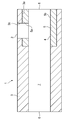
- FIG. 1 is a schematic diagram of a sleeve 1 for die casting.
- the die-casting sleeve 1 has a molten metal supply port 2 that opens upward, a molten metal outlet 6 that opens to the left, and a plunger insertion port 8 that opens to the right.
- a flow path 7 is provided inside the die casting sleeve 1.
- a molten metal supply port 2 for supplying a molten metal to the flow path 7 from the outside penetrates from the inner surface of the die casting sleeve 1 to the outer surface.
- the molten metal supplied to the flow path 7 from the outside via the molten metal supply port 2 is pushed by a plunger (not shown) inserted from the plunger insertion port 8 and is transferred from the molten metal emission port 6 to the outside (mold cavity). Emitted.
- the preliminary body 3 is prepared.
- the preliminary body 3 is a cylindrical member.
- a part of the inner surface of the preliminary body 3 forms a part of the flow path 7.
- a part of the inner surface of the preliminary body 3 is provided with an enlarged diameter portion 3 a having a diameter larger than that of the flow path 7.
- a first opening 3 b forming a part of the molten metal supply port 2 is provided on the side surface of the preliminary body 3.
- the cylindrical member 5 is disposed in the enlarged diameter portion 3a.
- the outer diameter of the member 5 is the same as or slightly larger than the inner diameter of the enlarged diameter portion 3a.
- the inner surface of the member 5 forms a flow path 7.
- the member 5 is provided with a second opening 5a that forms the molten metal supply port 2 together with the first opening 3b.
- at least a portion 4 facing the second opening 5a is formed of a sleeve material having the above component composition.
- the entire member 5 is formed of a sleeve material having the above component composition.
- a part or the whole of the die casting sleeve 1 may be heat-treated (quenched and tempered) to be adjusted to a predetermined hardness.
- the molten metal supply port 2 is formed by combining the preliminary body 3 having the first opening 3b and the member 5 having the second opening 5a. Not limited to.
- the molten metal supply port 2 is formed by forming a through-hole penetrating from the outside to the inside of the preliminary body 3 and the member 5. It may be formed. That is, the order in which the sleeve material (member 5) having the above-described component composition is provided in the “site facing the molten metal supply port” with respect to the preliminary body 3 after the molten metal supply port 2 is provided. In this order, the sleeve material (member 5) having the above-described component composition is provided on the “part facing the part serving as the melt supply port” with respect to the preliminary body 3 before the melt supply port 2 is provided. Also good.
- the member 5 having the above-described component composition can be a cast material or a sintered material produced by a powder metallurgy method.
- a material having the above-described component composition is lined by a technique such as overlay welding or thermal spraying, or a ring having the above-described component composition.
- a shaped part may be shrink-fitted. In the case of the shrink-fitting method, a compressive stress can be applied to the ring-shaped component, so that it is possible to prevent the ring-shaped component from being cracked.
- the sleeve material having the above component composition is an “article pre-formed before being provided” such as a cylindrical member or a ring-shaped member
- the preliminary body 3 and the member 5 are arranged before the member 5 is arranged.
- the preliminary body 3 (that is, the inner surface of the flow path 7 excluding the inner surface of the member 5 in the case of FIG. 1) is adjusted to a hardness that emphasizes toughness of “40 to 48 HRC”, while the member 5 is set to “50 HRC or more. If the hardness is adjusted so as to emphasize the resistance to melting damage, it is effective to improve the life of the die casting sleeve 1 as a whole. For example, it is preferable to adjust the hardness of the member 5 to a range of 50 to 75 HRC. By increasing the hardness of the member 5, the pressure resistance strength of the member 5 is improved and the resistance to physical melting is improved.
- the carbide of the metal structure of the member 5 is enriched with the heat treatment and the distribution thereof is uniform, which contributes to the improvement of resistance to physical erosion. That is, it is preferable that the member 5 is harder because resistance to physical melting is improved.
- the member 5 in order to make the member 5 hard, it is effective to increase the C content of the member 5, for example, it is preferable to set the C content to 1.0% or more.
- the member 5 having a C content of 1.0% or more is preferably, for example, the above-described “sintered material”.
- the carbide in the structure of the member 5 can be made fine and uniform, and further, the structure itself can be made fine, which is advantageous for maintaining and improving excellent toughness. In this case, sufficient toughness can be ensured even if the member 5 is adjusted to a hardness of “over 60 HRC”, or actually adjusted to a hardness of about 75 HRC.
- composition having a C content of 1.0% or more include, for example, C: 1.0% to 2.5%, Si: 1.0% or less, Mn: 1.0% or less, Cr: 3.0% to 12.0%, one or two of Mo and W according to the relational expression (Mo + 1 / 2W): 10.0% to 15.0%, V: 3.0 % Or more and 6.0% or less, and the component composition of the remaining Fe and impurities. And this component composition can further contain at least one of Co and Nb of Co: 10.0% or less and Nb: 3.0% or less.
- the hardness of the member 5 is easily increased.
- the C content is less than 1.0%, as described in detail below, it is effective from the viewpoint of suppressing cracking of the member 5 due to thermal shock and economical efficiency, and the C content is 1.0%. Less than is preferable.
- the hardness of the member 5 is preferably “60 HRC or less”. More preferably, it is 58 HRC or less, More preferably, it is less than 55 HRC, More preferably, it is less than 54 HRC. And in the case of the member 5 of such hardness, C content can be made into less than 1.0%, for example.
- compositions having a C content of less than 1.0% include C: 0.4% or more and less than 1.0%, Si: 1.0% or less, Mn: 1.0% or less, Cr: 3.0 % Or more and less than 7.0%, one or two of Mo and W according to the relational expression (Mo + 1 / 2W): 1.6% or more and 15.0% or less, V: 0.5% or more and 6.0 % Or less, and the composition of the balance Fe and impurities is preferable.
- this component composition can further contain at least one of Co and Nb of Co: 10.0% or less and Nb: 3.0% or less.
- the member 5 having C of less than 1.0% may be a sintered material.
- the member 5 is an “article formed after being provided” such as a welding material or a thermal spray material, as described above, a part or the whole of the sleeve 1 for die casting after the member 5 is disposed is heat-treated. Become. When the entire die casting sleeve 1 is heat-treated “simultaneously”, the material (component) that can achieve a desired balance between hardness and toughness under the common heat-treatment conditions in both the preliminary body 3 and the member 5. It is effective to select the composition. Alternatively, it is possible to select an optimum heat treatment condition for either the preliminary body 3 or the member 5.
- the component composition of the member 5 has a composition in which the above-described C content is 1.0% or more, or the C content is 1. Any composition of less than 0% can be applied.
- a technique in which a welding material or a thermal spray material is applied to the member 5 the concern that the arranged member 5 is displaced or detached from the inner surface of the preliminary body 3 is reduced.
- a part (preliminary body 3) that does not require any special measures against melting damage can be manufactured with a general-purpose / low-priced material such as SKD61, which is advantageous in reducing labor and cost for manufacturing. It is. Moreover, since the site
- the sleeve for die casting of the present invention is preferably composed of the material (sleeve material) having the above-described component composition in at least a portion facing the molten metal supply port on the inner surface forming the flow path, and at least the molten metal supply port.
- the inner surface other than the portion facing the surface is composed of “another material” having a component composition different from that of the sleeve material.
- the above-mentioned “parts facing at least the molten metal supply port” are, for example, “a part of the entire circumference (for example, from the part facing the molten metal supply port to the part of the molten metal supply port” on the cylindrical inner surface forming the flow path, for example. All internal surfaces of the member 5 in FIG. 1) ”. Further, the above “at least the portion facing the molten metal supply port” faces the molten metal supply port with respect to the total length of the flow path (the length from the plunger insertion port 8 to the molten metal discharge port 6 in FIG. 1), for example. It may be “a length up to half or less of the total length (for example, all inner surfaces of the member 5 in FIG. 1)” including the portion.
- the component composition of the “other material” is, for example, mass%, C: 0.30% or more and 0.50% or less, Si: 1.5% or less, Mn: 1.0% or less, Cr : 4.0% or more and 6.0% or less, one or two of Mo and W according to the relational expression (Mo + 1 / 2W): 0.8% or more and less than 1.6%, V: 0.3% Or more, 1.5% or less, Co: 0% or more and 1.0% or less, Nb: 0% or more and 0.3% or less, balance Fe and impurities.
- P, S, Ni, Cu, Al, Ca, Mg, O (oxygen), and N (nitrogen) are elements that may remain in the material as impurities.
- At least a portion other than the portion 4 facing the molten metal supply port 2 in the inner surface forming the flow path 7 may be formed of a sleeve material having the above component composition.
- all inner surfaces forming the flow path 7 of the die casting sleeve 1 may be composed of the members 51 having the above-described component composition.
- the entire die casting sleeve can be made of a sleeve material having the above component composition. Then, a part or the whole of this die casting sleeve may be heat-treated to adjust to a predetermined hardness. About the point of this heat processing, the above-mentioned thing is applicable.
- the surface of the member 5 may be finished into a product shape by finishing machining or the like, if necessary.
- the thickness of the member 5 is preferably 2 mm or more in a state of being incorporated in the preliminary body 3. More preferably, it is 4 mm or more, More preferably, it is 7 mm or more, Most preferably, it is 10 mm or more. If the member 5 is a “member formed in advance before being provided” such as a cylindrical member or a ring-shaped member, the thickness of the ring-shaped article may be adjusted to be large. Alternatively, in the case of an “article to be molded after being provided” such as a welding material or a thermal spray material, “multi-layer deposition” may be performed at the time of overlay welding or thermal spraying.
- a surface treatment may be performed on the surface of the member 5 that forms the flow path 7. That is, the surface treatment layer 5 b may be provided on the surface of the member 5 that forms the flow path 7.
- the type of surface treatment can be appropriately selected from homo-treatment, physical vapor deposition, chemical vapor deposition and the like in addition to nitridation.
- the types of surface treatment layer 5b include nitride layers such as nitride layers and nitrogen diffusion layers, oxide layers, oxynitride layers, sulfur nitride layers mainly composed of sulfides and nitrides, etc. Is effective in suppressing chemical erosion. These surface treatment layers may be used in combination.
- the thickness of the surface treatment layer is preferably 0.2 mm or more and 0.5 mm or less.
- a layer having a “nitride layer” and an “oxide layer” on the nitride layer is preferable.
- the thickness of the nitride layer is more preferably greater than 0 mm and not less than 0.2 mm. Moreover, it is more preferable to set it as 0.4 mm or less.
- Such a nitrided layer can be formed by various known nitriding treatments such as gas soft nitriding treatment.
- the oxide layer is more preferably a “magnetite layer”.
- the thickness of the oxide layer is more preferably greater than 0 mm and not less than 0.001 mm. Moreover, it is more preferable to set it as 0.02 mm or less.
- Such an oxide layer can be formed by, for example, a known homotreatment or steam treatment.
- the surface treatment layer 5b described above is effective for suppressing chemical erosion. Even if the molten metal supplied vigorously from the molten metal supply port 2 to the flow path 7 breaks the surface treatment layer 5b, the member 5 having the above-described component composition existing below it is effective for further progress of the melting loss. Suppress it. Therefore, by providing the above-described member 5 in the portion 4 facing the molten metal supply port 2 in the inner surface forming the flow path 7 and further providing the surface treatment layer 5 b on the member 5, the die-casting sleeve 1 as a whole is resistant to melting damage. Further improve.
- the surface treatment layer 5 b may extend to the inner surface other than the portion 4 facing the molten metal supply port 2 among the inner surfaces forming the flow path 7.
- the surface treatment layer 5 b may be provided on a part forming the molten metal supply port 2, a part forming the molten metal outlet 6, or the entire inner surface forming the flow path 7.
- the inner surface of the flow path 7 other than the portion 4 facing the molten metal supply port 2 has a low degree of occurrence of physical melting damage, and therefore the surface treatment layer 5b having excellent ability to suppress chemical melting is provided. Contributes to comprehensive improvement in resistance to erosion.
- the portion facing the molten metal supply port refers to a portion that can be seen at least when the inner surface of the die casting sleeve is viewed from the opening direction of the molten metal supply port 2.
- the die casting sleeve is generally incorporated in a die casting apparatus in a posture in which the opening direction of the molten metal supply port extends in a substantially vertical downward direction. For this reason, it is good to provide the sleeve raw material of this invention strong with respect to a physical melting damage and a chemical melting damage in the site
- the molten metal supplied from the molten metal supply port of such a die casting sleeve may collide with a portion located at approximately 45 ° with respect to the above-described substantially vertical downward direction. For this reason, it is preferable to provide the sleeve material of the present invention also at the portion located at 45 °. Even in this case, the molten metal that has collided with the portion positioned at 45 ° flows toward the portion facing the molten metal supply port, and thus the facing portion may also be melted. For this reason, if the sleeve material is provided at a portion facing the molten metal supply port, melting damage can be reduced.
- Cylindrical die casting sleeve preliminary bodies A1 and B1 having dimensions of an outer diameter of 200 mm, an inner diameter of 85 mm, and a length of 550 mm were prepared.
- the material of the die casting sleeve preliminary bodies A1 and B1 is SKD61.
- a ring-shaped article having an outer diameter of 105 mm, an inner diameter of 85 mm, and a length of 200 mm was prepared as the member 5 provided on the inner surface of the die casting sleeve preliminary body A1 (ring thickness 10 mm).
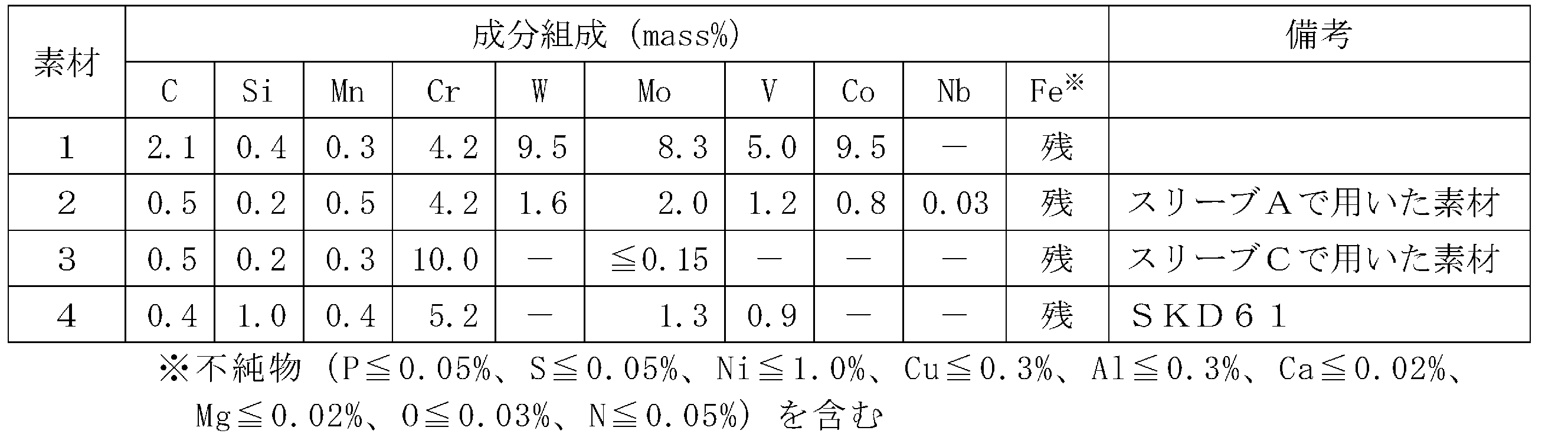
- This ring-shaped article has the composition shown in Table 1 and has a hardness adjusted to about 53 HRC by quenching and tempering.
- the ring-shaped article was shrink-fitted on the machined inner surface of the above-described die casting sleeve preliminary body A1. After the shrink fitting, a clamp ring was fixed to the end of the die casting sleeve preliminary body A1 so that the ring-shaped article did not come off from the die casting sleeve preliminary body A1.
- the side surface of the die casting sleeve preliminary body A1 after shrink-fitting this ring-shaped article was machined to provide a molten metal supply port 2.
- the molten metal supply port 2 was provided at a position 60 to 160 mm in the longitudinal direction from the end where the plunger insertion port 8 was provided. Also, finishing machining was performed on the inner surface of the ring-shaped article after the shrink fitting.
- a flow path is formed by the inner surface of the die casting sleeve preliminary body A1 and the inner surface of the ring-shaped article.
- the appearance of the die-casting sleeve A (or die-casting sleeves B to D described later) is shown in FIG.
- sleeve B for die casting (comparative example)-
- the entire die casting sleeve preliminary body B1 was quenched and tempered to adjust the hardness to about 45 HRC.
- a molten metal supply port 2 is provided on the side surface of this die casting sleeve preliminary body B.
- the molten metal supply port 2 is provided at a position of 60 to 160 mm in the length direction from the end portion where the plunger insertion port 8 is provided.
- a surface treatment was performed on “all inner surfaces” of the die casting sleeve preliminary body B1 after quenching and tempering to obtain a die casting sleeve B of a comparative example.
- a nitride layer having a thickness of about 0.3 mm was formed on the inner surface of the die casting sleeve by gas soft nitriding to form a surface treatment layer 5b.
- the observation result of the sleeve A for die casting is shown in FIG. 4, and the observation result of the sleeve B for die casting is shown in FIG.
- a sound surface treatment layer 5b remained on the inner surface of the die-casting sleeve A, and no chemical or physical melting damage was observed.
- the surface treatment layer 5b is destroyed on the inner surface of the die casting sleeve B immediately below the molten metal supply port 2, and the material (that is, SKD61) is also worn out. Remarkable melting damage was observed.
- Cylindrical die casting sleeve preliminary bodies C1 and D1 having an outer diameter of 200 mm, an inner diameter of 85 mm, and a length of 550 mm were prepared.
- the material of the die casting sleeve preliminary bodies C1 and D1 is SKD61.
- sleeve C for die casting (example of the present invention)-
- the inner surface of the die casting sleeve preliminary body C1 was machined, and the inner diameter of the portion from the end where the plunger insertion port 8 is provided to 200 mm in the longitudinal direction was set to 95 mm.
- a welding rod having the component composition shown in Table 2 was prepared as the member 5 provided on the inner surface of the die casting sleeve preliminary body C1.
- two overlay layers were formed on the machined inner surface of the die casting sleeve preliminary body C by overlay welding using the welding rod.
- the entire die casting sleeve preliminary body C after overlay welding was subjected to quenching and tempering so that the hardness of the SKD 61 portion was about 45 HRC. Thereby, the hardness of the built-up layer became about 45 HRC.
- the side surface of the die casting sleeve preliminary body C after the build-up layer was formed was machined to provide the molten metal supply port 2.
- the molten metal supply port 2 was provided at a position of 60 to 160 mm in the length direction from the end where the plunger insertion port was provided. Finishing machining was performed on the built-up layer, so that the finished thickness of the built-up layer was about 5 mm.
- a flow path was formed on the inner surface of the die casting sleeve preliminary body C1.
- Surface treatment was performed on “all inner surfaces” of the die casting sleeve preliminary body C1 to obtain the die casting sleeve C of the example.
- a nitride layer having a thickness of about 0.3 mm is formed on the inner surface of the die casting sleeve by gas soft nitriding, and a magnetite layer having a thickness of about 0.01 mm is formed on the nitride layer by steam treatment.
- Surface treatment layer 5b was obtained.
- sleeve D for die casting (comparative example)-
- the entire die casting sleeve preliminary body D1 was quenched and tempered to adjust the hardness to about 45 HRC.
- a molten metal supply port 2 is provided at a position 60 to 160 mm in the length direction from the end portion where the plunger insertion port 8 is provided.
- Surface treatment was performed on “all inner surfaces” of the die casting sleeve preliminary body D1 after quenching and tempering to obtain a die casting sleeve D of a comparative example.
- a nitride layer having a thickness of about 0.3 mm was formed on the inner peripheral surface of the die casting sleeve by gas soft nitriding to form a surface treatment layer 5b.
- the molten metal supplied from the molten metal supply port 2 was poured with a momentum so as to fall to a position obliquely below 45 ° from the molten metal supply port 2. After die casting, the inner surface of the position where the melt supply port 2 of both sleeves was provided was observed.
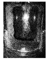
- FIG. 6 is a photograph of the part 4 facing the molten metal supply port 2 in the sleeve C for die casting after the die casting is performed 4,500 times.
- a circle indicates a position 45 ° obliquely below the molten metal supply port 2
- an asterisk indicates a position immediately below the molten metal supply port 2.
- FIG. 6 with respect to the die-casting sleeve C, physical melting damage was observed at a position 45 ° obliquely downward from the molten metal supply port 2 where the impact energy due to the molten metal is considered to be large at the time of 4,500 shots.
- the built-up layer still remained.
- a sound surface treatment layer 5b remains immediately below the molten metal supply port 2, and both chemical and physical melting damage is suppressed.
- FIG. 7 is a photograph of the part 4 facing the molten metal supply port 2 in the die-casting sleeve D after 500 times of die-casting.
- a circle indicates a position 45 ° obliquely below the molten metal supply port 2
- an asterisk indicates a position immediately below the molten metal supply port 2.
- significant physical melting damage was observed at a position obliquely below 45 ° from the molten metal supply port 2, and immediately below the molten metal supply port 2.
- significant chemical erosion was observed.
- Table 3 shows the component composition of the evaluated materials.
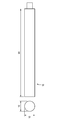
- the materials 1 to 4 in Table 3 were processed into the shape of the test piece 16 having the dimensions (unit: mm) shown in FIG.
- the raw material 1 is a sintered material obtained by subjecting a metal powder having the component composition shown in Table 3 to HIP (hot isostatic pressing) treatment.
- the hardness of each test piece 16 is material 1:70 HRC, material 2:53 HRC, material 3:45 HRC, material 4:45 HRC.
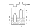
- the test piece 16 was moved up and down at a cycle of 90 rpm and a reciprocating height of 30 mm as shown in FIG.
- the molten metal 17 is an aluminum alloy AC4C (Fe: 0.5 mass% or less) standardized in “aluminum alloy casting” of JIS-H-5202: 2010, and the temperature thereof is maintained at 700 ° C. by the heater 18. .
- the test time was 2 hours.
- the specimens of the materials 1 to 3 were less worn than the specimen of the material 4 and excellent in chemical erosion resistance.
- the form of physical melting that could be caused by moving the specimen up and down was not confirmed.
- the test piece of the material 1 having a C content higher than 1.0% and a high content of W, Mo, V is also high in hardness. Excellent resistance to erosion.
- a sleeve for die casting having excellent melt resistance and a manufacturing method thereof are provided.
Landscapes
- Chemical & Material Sciences (AREA)
- Engineering & Computer Science (AREA)
- Mechanical Engineering (AREA)
- Materials Engineering (AREA)
- Metallurgy (AREA)
- Organic Chemistry (AREA)
- Physics & Mathematics (AREA)
- Thermal Sciences (AREA)
- Crystallography & Structural Chemistry (AREA)
- Molds, Cores, And Manufacturing Methods Thereof (AREA)
Abstract
Description
本発明の目的は、耐溶損性に優れたダイカスト用スリーブと、その製造方法を提供することである。
内部に流路を有するダイカスト用スリーブであって、
外部から前記流路へ金属溶湯を供給するための溶湯供給口が前記ダイカスト用スリーブの内面から外面に貫通しており、
前記流路をなす内面のうち少なくとも前記溶湯供給口に向かい合う部位が、質量%で、C:0.4%以上2.5%以下、Si:1.0%以下、Mn:1.0%以下、Cr:3.0%以上12.0%以下、残部Feおよび不純物の成分組成を有する素材で構成されている、ダイカスト用スリーブが提供される。
内部に流路を有し、外部から前記流路へ金属溶湯を供給するための溶湯供給口が外面から内面へ貫通しているダイカスト用スリーブの製造方法であって、
前記ダイカスト用スリーブとなる予備体を用意し、
前記流路をなす内面のうち少なくとも、前記溶湯供給口と向かい合う部位または前記溶湯供給口となる部位に向かい合う部位に、質量%で、C:0.4%以上2.5%以下、Si:1.0%以下、Mn:1.0%以下、Cr:3.0%以上12.0%以下、残部Feおよび不純物の成分組成を有する素材を設ける、ダイカスト用スリーブの製造方法が提供される。
例えば、一般的なアルミダイカスト鋳造の場合、鋳造材料にはJIS-H-5302:2006の「アルミニウム合金ダイカスト」に規定されるADC12(Fe:1.3質量%以下)が使用され、その鋳造時の金属溶湯の温度は660~680℃である。自動車部品のなかには、軽量化のために、鉄製からアルミニウム合金製に変更されるものがある。こうした変更においては、鉄からアルミニウム合金への変更に伴い低下するダイカスト製品の強度を補償することがある。
また、上記の強度補償のために、アルミニウム合金中のFe量を低減することで、ダイカスト製品の強度を向上させる手法が多く利用されている。そして、このFeの含有量が「0%」のレベルにまで低減された特殊なアルミニウム合金の場合、化学的溶損が加速される。
このような、特殊なダイカスト鋳造においては、従来の表面処理層を有するダイカスト用スリーブであっても、その化学的溶損の抑制効果は限定的であった。
Cは、Cr、W、Mo、V、Nbと結合して炭化物を形成し、ダイカスト用スリーブの耐摩耗性を向上する元素である。耐摩耗性の向上は、物理的溶損の抑制に効果的である。しかし、多すぎると、靭性が低下する。よって、後述するCr、W、Mo、VおよびNbの含有量とバランスさせた上で、0.4%以上2.5%以下とする。
なお、好ましくはCが0.4%以上1.0%未満である。Cの含有量がこの範囲内であればスリーブ素材の靱性と高温強度とを両立させやすい。さらに好ましくはCは0.9%以下である。そして、よりさらに好ましくはCは0.8%以下であり、特に好ましくはCは0.6%以下である。また、さらに好ましくはCは0.42%超である。そして、よりさらに好ましくはCは0.43%以上であり、特に好ましくはCは0.44%以上である。
あるいは、好ましくはCが1.0%以上2.5%以下であり、この場合にはスリーブ素材は、粉末材料を焼結して得た焼結材とすることが好ましい。そして、この焼結材は、得ようとするスリーブ素材の組成と同じ組成を有する金属粉末を焼結して得ることが好ましい。焼結の際には、HIP(熱間静水圧プレス)処理を用いることが好ましい。一般的にCの含有量が多くなると素材の高温強度は高くなるが、炭化物が粗大になりやすく、または偏析しやすく靱性が低くなりがちである。しかし金属粉末を焼結することにより組織中の炭化物を微細かつ均等に形成しやすく、さらには組織自体を微細にしやすいので、素材の靱性を高めやすい。より好ましくはCは1.2%以上である。さらに好ましくはCは1.5%以上である。よりさらに好ましくはCは1.7%以上である。また、より好ましくはCは2.3%以下である。
Siは、通常、溶解工程における脱酸剤として使用される。そして、スリーブ素材の被削性を高める効果がある。しかし、多すぎると、スリーブ素材の靭性が低下する。よって、Siは、1.0%以下とする。好ましくは0.6%以下である。より好ましくは0.5%以下である。また、Siの下限は特に定めないが(0%としてもよいが)、0%より多いことが好ましい。Si量はより好ましくは0.1%以上である。
Mnは、Siと同様、脱酸剤として使用される。そして、焼入性を高めて、ダイカスト用スリーブに適度の焼入れ焼戻し硬さを付与する効果がある。しかし、多すぎると、焼入れ焼戻し後の組織中に残留オーステナイトが多くなり、靭性を低下させる。よって、Mnは、1.0%以下とする。好ましくは0.7%以下である。より好ましくは0.6%以下である。また、Mnの下限は特に定めないが(0%としてもよいが)、0%より多いことが好ましい。Mn量はより好ましくは0.1%以上である。さらに好ましくは0.2%以上である。
Crは、焼入性を高めて、また炭化物を形成して、スリーブ素材の耐摩耗性を向上するのに有効な元素である。耐摩耗性の向上は、物理的溶損の抑制に効果的である。また、Crの融点は約1903℃であり、Feの融点(約1539℃)よりも高く、金属溶湯との反応をし難くする元素であることから、Crは化学的溶損の抑制にも効果的な元素である。但し、多すぎると、靱性や高温強度の低下を招く。よって、Crは、3.0%以上12.0%以下とする。好ましくは3.5%以上である。より好ましくは4.0%以上である。また、好ましくは11.0%以下である。
なお、ダイカスト用スリーブに求められる靱性と耐溶損性との特性の関係で、耐溶損性を重視する場合、Crは7.0%以上とすることが好ましい。より好ましくは8.0%以上、特に好ましくは9.0%以上である。また、靱性を重視する場合、Crは7.0%未満とすることが好ましい。より好ましくは6.0%以下、特に好ましくは5.0%以下である。
MoおよびWは、Cと結合して炭化物を形成し、ダイカスト用スリーブに耐摩耗性を付与して、物理的溶損を抑制する元素である。また、Moの融点が約2620℃、Wの融点が約3380℃とFeの融点より高く、MoおよびWは化学的溶損の抑制にも効果的な元素である。そして、焼戻し時の二次硬化作用が大きく、高温強度も付与できる元素である。但し、多すぎると被削性や靭性の低下を招く。
MoおよびWは、必要に応じて、単独または複合で含有することができる。このときの含有量は、WがMoの約2倍の原子量であることから、(Mo+1/2W)の関係式で定義される「Mo当量」で一緒に規定することができる。そして、本発明において、MoとWの少なくとも一方を含有する場合、上記の関係式において1.6%以上を含有する必要がある。より好ましくは2.0%以上である。特に好ましくは2.5%以上である。そして、MoとWの少なくとも一方は、(Mo+1/2W)の関係式による値で15.0%以下を含有することができる。好ましくは10.0%以下である。より好ましくは5.0%以下である。そして、靱性を重視したいとき等、特に好ましくは3.0%以下である。
なお、MoおよびWの各々の元素について、Mo:1.0%以上、1/2W:0.6%以上を含有することも好ましい。
・V:6.0%以下
Vは、Cと結合して硬質の炭化物を形成し、ダイカスト用スリーブの耐摩耗性の向上に寄与して、物理的溶損を抑制する元素である。そして、Vの融点は約1847℃とFeの融点より高く、化学的溶損の抑制にも効果的に働く元素である。しかし、多すぎると、靭性が低下する。よって、Vは、必要に応じて、6.0%以下を含有することができる。好ましくは4.0%以下である。より好ましくは3.0%以下である。さらに好ましくは2.0%以下である。また、Vを含有する場合、好ましくは0.5%以上である。より好ましくは1.0%以上である。さらに好ましくは1.1%以上である。特に好ましくは1.2%超である。
・Co:10.0%以下
Coは、基地(matrix)中に固溶して、スリーブ素材の強度や耐熱性を向上させる元素である。しかし、多すぎると、靱性を低下させる。よって、本発明では、必要に応じて、10.0%以下のCoを含有することができる。好ましくは5.0%以下である。より好ましくは3.0%以下である。特に好ましくは2.0%以下である。また、Coの下限は特に定めないが(0%としてもよいが)、0%以上とすることができる。Coを含有する場合、好ましくは0.5%以上である。
Nbは、炭化物を形成して、スリーブ素材の基地の強化や耐摩耗性を向上する元素である。また、融点が約2415℃と高く、化学的溶損の抑制に働く元素である。しかし、多すぎると、スリーブ素材の被削性の低下を招く。よって、Nbは、必要に応じて、3.0%以下を含有することができる。好ましくは2.0%以下である。より好ましくは1.0%以下である。また、Nbの下限は特に定めないが(0%としてもよいが)、0%以上とすることができる。Nbを含有する場合、0.01%以上の含有で、上記の効果を得ることが可能である。
まず、予備体3を用意する。本実施形態において、予備体3は筒状の部材である。予備体3の内面の一部は流路7の一部を形成している。予備体3の内面の一部には、流路7よりも大径の拡径部3aが設けられている。予備体3の側面には溶湯供給口2の一部をなす第一開口3bが設けられている。
例えば、部材5の硬さを50~75HRCの範囲に調整することが好ましい。部材5の硬さを高めることで、この部材5の耐圧強度が向上して、物理的溶損への耐性が向上する。また、上記の熱処理に伴って、部材5の金属組織の炭化物が富化されて、かつ、その分布も均一になり、物理的溶損への耐性の向上に寄与することも考えられる。つまり、部材5が硬いほど物理的溶損への耐性が向上するので好ましい。
熱衝撃による部材5の割れの抑制に配慮した場合、部材5の硬さは「60HRC以下」が好ましい。より好ましくは58HRC以下、さらに好ましくは55HRC未満、よりさらに好ましくは54HRC未満である。そして、このような硬さの部材5の場合、例えば、Cの含有量を1.0%未満とすることができる。このことによって、部材5を鋳造材にしても(焼結材にしなくても)、優れた靱性を確保できる。このC含有量が1.0%未満の組成として、例えば、C:0.4%以上1.0%未満、Si:1.0%以下、Mn:1.0%以下、Cr:3.0%以上7.0%未満、(Mo+1/2W)の関係式によるMoおよびWのうちの1種または2種:1.6%以上15.0%以下、V:0.5%以上6.0%以下、残部Feおよび不純物の成分組成とすることが好ましい。そして、この成分組成に、さらに、Co:10.0%以下、Nb:3.0%以下の、CoおよびNbの少なくとも一種を含むことができる。
なお、Cが1.0%未満の部材5も、勿論、焼結材としてもよい。
SKD61の場合、質量%で、C:0.35%以上0.42%以下、Si:0.80%以上1.20%以下、Mn:0.25%以上0.50%以下、P:0.030%以下、S:0.020%以下、Cr:4.80%以上5.50%以下、Mo:1.00%以上1.50%以下、V:0.80%以上1.15%以下、残部Feおよび不純物である。
部材5の厚さは、予備体3に組み込まれた状態で、2mm以上であることが好ましい。より好ましくは4mm以上、さらに好ましくは7mm以上、特に好ましくは10mm以上である。このような厚さは、部材5が、筒状部材やリング状部材等の“設ける前に予め成形された部材”であるなら、そのリング状物品の肉厚を大きく調整すればよい。あるいは、溶接材や溶射材といった“設けた後に成形される物品”であるなら、その肉盛溶接や溶射の際に“多層盛り”を実施すればよい。
表面処理の種類は、窒化処理等に加えて、ホモ処理、物理蒸着法や化学蒸着法等、適宜選択することが可能である。そして、表面処理層5bの種類として、特に、窒化物層や窒素拡散層等の窒化層、酸化物層、酸窒化物層、主に硫化物と窒化物とで構成される浸硫窒化層等が化学的溶損の抑制に効果的である。これらの表面処理層は、組み合わせて使用してもよい。表面処理層の厚みは0.2mm以上0.5mm以下とすることが好ましい。
窒化層の厚さは、0mmより大きく0.2mm以上とすることがより好ましい。また、0.4mm以下とすることがより好ましい。このような窒化層は、例えば、ガス軟窒化処理といった、既知の各種窒化処理で形成することができる。
また、酸化物層は「マグネタイト層」であることがより好ましい。酸化物層の厚さは、0mmより大きく0.001mm以上とすることがより好ましい。また、0.02mm以下とすることがより好ましい。このような酸化物層は、例えば、既知のホモ処理や水蒸気処理等で形成することができる。
寸法が、概ね、外径200mm×内径85mm×長さ550mmの円筒状のダイカスト用スリーブ予備体A1およびB1を準備した。ダイカスト用スリーブ予備体A1およびB1の材質は、SKD61である。
ダイカスト用スリーブ予備体A1の内面に機械加工を施し、プランジャー挿入口8が設けられる端部から長手方向に200mmまでの部位の内径を105mmとした。機械加工後のダイカスト用スリーブ予備体A1の全体に焼入れ焼戻しを行って、硬さを約45HRCに調整した。

ダイカスト用スリーブ予備体B1の全体に焼入れ焼戻しを行って、硬さを約45HRCに調整した。このダイカスト用スリーブ予備体Bの側面に、溶湯供給口2が設けられている。溶湯供給口2はプランジャー挿入口8が設けられた端部から長さ方向に60~160mmの位置に設けられている。そして、この焼入れ焼戻し後のダイカスト用スリーブ予備体B1の“全ての内面”に表面処理を行って、比較例のダイカスト用スリーブBとした。ダイカスト用スリーブの内面上に、ガス軟窒化処理によって、厚さ約0.3mmの窒化層を形成して、表面処理層5bとした。
ダイカスト用スリーブA(実施例)およびB(比較例)を800tのコールドチャンバー方式ダイカスト装置に装着して、ダイカスト用アルミニウム合金ADC12(Fe:1.3質量%以下)のダイカスト鋳造を行った。ダイカスト鋳造時のADC12の金属溶湯の温度は680℃とした。そして、ショット回数(ダイカスト鋳造を行った回数)が40,000回に達したときの、両スリーブの溶湯供給口2が設けられている位置の内面を観察した。
外径200mm×内径85mm×長さ550mmの円筒状のダイカスト用スリーブ予備体C1およびD1を準備した。ダイカスト用スリーブ予備体C1およびD1の材質は、SKD61である。
ダイカスト用スリーブ予備体C1の内面に機械加工を施し、プランジャー挿入口8が設けられる端部から長手方向に200mmまでの部位の内径を95mmとした。
一方、ダイカスト用スリーブ予備体C1の内面に設ける部材5として、表2の成分組成を有する溶接棒を準備した。そして、この溶接棒を用いた肉盛溶接で、ダイカスト用スリーブ予備体Cの機械加工した内面に2層の肉盛層を形成した。
そして、SKD61の部分の硬さが約45HRCになるように、肉盛溶接後のダイカスト用スリーブ予備体Cの全体に焼入れ焼戻しを行った。これにより、肉盛層の硬さも約45HRCとなった。
その後に、この肉盛層を形成した後のダイカスト用スリーブ予備体Cの側面に機械加工を行って、溶湯供給口2を設けた。溶湯供給口2は、プランジャー挿入口が設けられた端部から長さ方向に60~160mmの位置に設けた。
肉盛層に仕上げの機械加工を行って肉盛層の仕上げ厚さを約5mmとした。これにより、ダイカスト用スリーブ予備体C1の内面に流路を形成した。
ダイカスト用スリーブ予備体C1の“全ての内面”に表面処理を行って、実施例のダイカスト用スリーブCとした。ダイカスト用スリーブの内面上に、まず、ガス軟窒化処理によって厚さ約0.3mmの窒化層を形成し、この窒化層の上に水蒸気処理によって厚さ約0.01mmのマグネタイト層を形成して、表面処理層5bとした。

ダイカスト用スリーブ予備体D1の全体に焼入れ焼戻しを行って、硬さを約45HRCに調整した。このダイカスト用スリーブ予備体D1の側面には、プランジャー挿入口8が設けられた端部から長さ方向に60~160mmの位置に、溶湯供給口2が設けられている。
この焼入れ焼戻し後のダイカスト用スリーブ予備体D1の“全ての内面”に表面処理を行って、比較例のダイカスト用スリーブDとした。ダイカスト用スリーブの内周面上に、ガス軟窒化処理によって、厚さ約0.3mmの窒化層を形成して、表面処理層5bとした。
ダイカスト用スリーブC(実施例)およびD(比較例)を800tのコールドチャンバー方式ダイカスト装置に装着して、ダイカスト用アルミニウム合金(Fe:0.6%未満)のダイカスト鋳造を行った。ダイカスト鋳造時のアルミニウム合金の金属溶湯の温度は720℃とした。
次に、上記の試験片16を、図9に示すように、周期90rpm、往復高さ30mmで上下動させて、金属溶湯17への浸漬を繰り返す溶損試験を行った。金属溶湯17は、JIS-H-5202:2010の「アルミニウム合金鋳物」に規格されるアルミニウム合金AC4C(Fe:0.5質量%以下)であり、その温度は、ヒーター18によって700℃に維持した。試験時間は2時間とした。
そして、溶損試験の前後において、その試験片の重さの差(つまり、減量)に基づき、下記の式に従って、溶損率(%)を算出した。この溶損率の値が小さい程、耐化学的溶損性に優れることを意味する。結果を表4に示す。
溶損率(%)={(試験前の重さ-試験後の重さ)/試験前の重さ}×100

2 溶湯供給口
3 予備体
3a 拡径部
3b 第一開口
4 溶湯供給口に向かい合う部位
5、51 部材
5a 第二開口
5b 表面処理層
6 溶湯出射口
7 流路
8 プランジャー挿入口
16 試験片
17 金属溶湯
18 ヒーター
Claims (12)
- 内部に流路を有するダイカスト用スリーブであって、
外部から前記流路へ金属溶湯を供給するための溶湯供給口が前記ダイカスト用スリーブの外面から内面に貫通しており、
前記流路をなす内面のうち少なくとも前記溶湯供給口に向かい合う部位が、質量%で、C:0.4%以上2.5%以下、Si:1.0%以下、Mn:1.0%以下、Cr:3.0%以上12.0%以下、Mo:1.0%未満、残部Feおよび不純物の成分組成を有する素材で構成されている、ダイカスト用スリーブ。 - 内部に流路を有するダイカスト用スリーブであって、
外部から前記流路へ金属溶湯を供給するための溶湯供給口が前記ダイカスト用スリーブの外面から内面に貫通しており、
前記流路をなす内面のうち少なくとも前記溶湯供給口に向かい合う部位が、質量%で、C:0.4%以上2.5%以下、Si:1.0%以下、Mn:1.0%以下、Cr:3.0%以上12.0%以下、(Mo+1/2W)の関係式によるMoおよびWのうちの1種または2種:1.6%以上15.0%以下、残部Feおよび不純物の成分組成を有する素材で構成されている、ダイカスト用スリーブ。 - 前記素材の成分組成が、質量%で、C:0.4%以上1.0%未満である、請求項1または2に記載のダイカスト用スリーブ。
- 前記素材の成分組成が、質量%で、C:1.0%以上2.5%以下であり、かつ、
前記素材が焼結材である、請求項1または2に記載のダイカスト用スリーブ。 - 前記素材の成分組成がさらに、Vを含み、質量%で、V:6.0%以下である、請求項1から4のいずれか一項に記載のダイカスト用スリーブ。
- 前記素材の成分組成がさらに、Co、Nbの少なくとも一つを含み、質量%で、Co:10.0%以下、Nb:3.0%以下である、請求項1から5のいずれか一項に記載のダイカスト用スリーブ。
- 内部に流路を有し、外部から前記流路へ金属溶湯を供給するための溶湯供給口が外面から内面へ貫通しているダイカスト用スリーブの製造方法であって、
前記ダイカスト用スリーブとなる予備体を用意し、
前記流路をなす内面のうち少なくとも、前記溶湯供給口と向かい合う部位または前記溶湯供給口となる部位に向かい合う部位に、質量%で、C:0.4%以上2.5%以下、Si:1.0%以下、Mn:1.0%以下、Cr:3.0%以上12.0%以下、Mo:1.0%未満、残部Feおよび不純物の成分組成を有する素材を設ける、ダイカスト用スリーブの製造方法。 - 内部に流路を有し、外部から前記流路へ金属溶湯を供給するための溶湯供給口が外面から内面へ貫通しているダイカスト用スリーブの製造方法であって、
前記ダイカスト用スリーブとなる予備体を用意し、
前記流路をなす内面のうち少なくとも、前記溶湯供給口と向かい合う部位または前記溶湯供給口となる部位に向かい合う部位に、質量%で、C:0.4%以上2.5%以下、Si:1.0%以下、Mn:1.0%以下、Cr:3.0%以上12.0%以下、(Mo+1/2W)の関係式によるMoおよびWのうちの1種または2種:1.6%以上15.0%以下、残部Feおよび不純物の成分組成を有する素材を設ける、ダイカスト用スリーブの製造方法。 - 前記素材の成分組成が、質量%で、C:0.4%以上1.0%未満である、請求項7または8に記載のダイカスト用スリーブの製造方法。
- 前記素材は、成分組成が、質量%で、C:1.0%以上2.5%以下の焼結材である、請求項7または8に記載のダイカスト用スリーブの製造方法。
- 前記素材の成分組成がさらに、Vを含み、質量%で、V:6.0%以下である、請求項7から10のいずれか一項に記載のダイカスト用スリーブの製造方法。
- 前記素材の成分組成がさらに、Co、Nbの少なくとも一つを含み、質量%で、Co:10.0%以下、Nb:3.0%以下である、請求項7から11のいずれか一項に記載のダイカスト用スリーブの製造方法。
Priority Applications (5)
| Application Number | Priority Date | Filing Date | Title |
|---|---|---|---|
| CN201780053624.1A CN109789481B (zh) | 2016-08-31 | 2017-04-17 | 压铸用套筒及其制造方法 |
| CN202111076150.7A CN113732263B (zh) | 2016-08-31 | 2017-04-17 | 压铸用套筒及其制造方法 |
| KR1020197006075A KR102335673B1 (ko) | 2016-08-31 | 2017-04-17 | 다이캐스트용 슬리브 및 그의 제조 방법 |
| JP2018536927A JP6722764B2 (ja) | 2016-08-31 | 2017-04-17 | ダイカスト用スリーブおよびその製造方法 |
| KR1020217028936A KR102434274B1 (ko) | 2016-08-31 | 2017-04-17 | 다이캐스트용 슬리브 및 그의 제조 방법 |
Applications Claiming Priority (2)
| Application Number | Priority Date | Filing Date | Title |
|---|---|---|---|
| JP2016-169254 | 2016-08-31 | ||
| JP2016169254 | 2016-08-31 |
Publications (1)
| Publication Number | Publication Date |
|---|---|
| WO2018042749A1 true WO2018042749A1 (ja) | 2018-03-08 |
Family
ID=61309173
Family Applications (1)
| Application Number | Title | Priority Date | Filing Date |
|---|---|---|---|
| PCT/JP2017/015503 Ceased WO2018042749A1 (ja) | 2016-08-31 | 2017-04-17 | ダイカスト用スリーブおよびその製造方法 |
Country Status (4)
| Country | Link |
|---|---|
| JP (1) | JP6722764B2 (ja) |
| KR (2) | KR102434274B1 (ja) |
| CN (2) | CN113732263B (ja) |
| WO (1) | WO2018042749A1 (ja) |
Cited By (1)
| Publication number | Priority date | Publication date | Assignee | Title |
|---|---|---|---|---|
| SE2050705A1 (en) * | 2020-06-12 | 2021-12-13 | Uddeholms Ab | Hot work tool steel |
Families Citing this family (3)
| Publication number | Priority date | Publication date | Assignee | Title |
|---|---|---|---|---|
| US10766068B2 (en) * | 2016-02-15 | 2020-09-08 | Hitachi Metals, Ltd. | Die-casting sleeve and its production method |
| KR102271199B1 (ko) | 2019-05-31 | 2021-06-30 | 한주금속(주) | 반응고 고압 주조장치용 슬리브 |
| JP6778837B1 (ja) * | 2020-03-06 | 2020-11-04 | 東京窯業株式会社 | ダイカスト用スリーブの設置構造及びダイカスト用スリーブ |
Citations (4)
| Publication number | Priority date | Publication date | Assignee | Title |
|---|---|---|---|---|
| JPH09262655A (ja) * | 1996-03-28 | 1997-10-07 | Toshiba Corp | ダイキャスト機部品およびそれを用いたダイキャスト機 |
| JP2004216413A (ja) * | 2003-01-14 | 2004-08-05 | Hitachi Metals Ltd | ダイカスト用スリーブ |
| JP2004292935A (ja) * | 2003-03-28 | 2004-10-21 | Hitachi Metals Ltd | 非鉄溶融金属用耐溶損性部材 |
| JP2006291285A (ja) * | 2005-04-11 | 2006-10-26 | Hitachi Metals Ltd | 非鉄溶融金属用耐溶損性部材 |
Family Cites Families (23)
| Publication number | Priority date | Publication date | Assignee | Title |
|---|---|---|---|---|
| EP0278208A1 (en) * | 1987-02-06 | 1988-08-17 | Weartech Limited | Wear resistant sleeve for use in a die casting machine |
| CH681068A5 (ja) * | 1989-12-22 | 1993-01-15 | Htm Ag | |
| JP3126471B2 (ja) * | 1992-03-19 | 2001-01-22 | 東京窯業株式会社 | ダイカストマシン用スリーブ |
| JP3107723B2 (ja) * | 1995-03-07 | 2000-11-13 | 株式会社クボタ | ダイカストマシンのプランジャースリーブ |
| JP3243985B2 (ja) * | 1995-10-23 | 2002-01-07 | 株式会社神戸製鋼所 | 耐溶損性及び保温性に優れた圧力鋳造用スリーブ |
| JPH11300461A (ja) * | 1998-04-20 | 1999-11-02 | Toshiba Mach Co Ltd | ダイカストマシン用スリーブ |
| JP2001025855A (ja) * | 1999-07-12 | 2001-01-30 | Toshiba Mach Co Ltd | ダイカストマシン用プランジャスリーブ及びその製造方法 |
| JP2001030051A (ja) * | 1999-07-19 | 2001-02-06 | Toshiba Mach Co Ltd | ダイカストマシン用プランジャスリーブ |
| JP2002283029A (ja) * | 2001-03-27 | 2002-10-02 | Hitachi Metals Ltd | ダイカスト用スリーブ |
| JP2004283899A (ja) * | 2003-03-25 | 2004-10-14 | Hitachi Metals Ltd | ダイカスト用スリーブ |
| WO2004087351A1 (ja) * | 2003-03-27 | 2004-10-14 | Kubota Corporation | ダイカストマシン用断熱プランジャースリーブ |
| JP2004291079A (ja) * | 2003-03-28 | 2004-10-21 | Hitachi Metals Ltd | 非鉄溶融金属用耐溶損性部材 |
| JP2005205666A (ja) * | 2004-01-21 | 2005-08-04 | Kubota Corp | 断熱性・耐熱変形性に優れた積層円筒体及びダイカストマシン用プランジャースリーブ |
| JP2006257507A (ja) * | 2005-03-17 | 2006-09-28 | Hitachi Metals Ltd | 非鉄溶融金属用合金 |
| JP2006272361A (ja) * | 2005-03-28 | 2006-10-12 | Hitachi Metals Ltd | ダイカスト用スリーブ |
| JP2006291331A (ja) * | 2005-04-14 | 2006-10-26 | Hitachi Metals Ltd | 非鉄溶融金属用耐溶損性部材 |
| JP2006315007A (ja) * | 2005-05-10 | 2006-11-24 | Hitachi Metals Ltd | ダイカスト用スリーブ |
| JP2007197784A (ja) * | 2006-01-27 | 2007-08-09 | Daido Steel Co Ltd | 合金鋼 |
| WO2007111257A1 (ja) * | 2006-03-24 | 2007-10-04 | Toshiba Kikai Kabushiki Kaisha | アルミダイカスト用給湯管 |
| DE202007000892U1 (de) * | 2007-01-16 | 2007-03-15 | Ortmann Druckgießtechnik GmbH Gießkammern-Gießbehälter-Druckgießwerkzeuge-Formenbau | Verschleißbüchse |
| JP5779749B2 (ja) * | 2011-04-11 | 2015-09-16 | 地方独立行政法人 岩手県工業技術センター | 鋳鉄材料の製造方法,鋳鉄材料及びダイカストマシン用スリーブ |
| JP5445712B1 (ja) * | 2013-07-05 | 2014-03-19 | 日立金属株式会社 | ダイカストスリーブの再生方法及び再生されたダイカストスリーブ |
| CN105499533A (zh) * | 2016-02-04 | 2016-04-20 | 中信戴卡股份有限公司 | 一种用于高压铸造的压射室及其生产方法 |
-
2017
- 2017-04-17 WO PCT/JP2017/015503 patent/WO2018042749A1/ja not_active Ceased
- 2017-04-17 KR KR1020217028936A patent/KR102434274B1/ko active Active
- 2017-04-17 CN CN202111076150.7A patent/CN113732263B/zh active Active
- 2017-04-17 CN CN201780053624.1A patent/CN109789481B/zh active Active
- 2017-04-17 JP JP2018536927A patent/JP6722764B2/ja active Active
- 2017-04-17 KR KR1020197006075A patent/KR102335673B1/ko active Active
Patent Citations (4)
| Publication number | Priority date | Publication date | Assignee | Title |
|---|---|---|---|---|
| JPH09262655A (ja) * | 1996-03-28 | 1997-10-07 | Toshiba Corp | ダイキャスト機部品およびそれを用いたダイキャスト機 |
| JP2004216413A (ja) * | 2003-01-14 | 2004-08-05 | Hitachi Metals Ltd | ダイカスト用スリーブ |
| JP2004292935A (ja) * | 2003-03-28 | 2004-10-21 | Hitachi Metals Ltd | 非鉄溶融金属用耐溶損性部材 |
| JP2006291285A (ja) * | 2005-04-11 | 2006-10-26 | Hitachi Metals Ltd | 非鉄溶融金属用耐溶損性部材 |
Cited By (2)
| Publication number | Priority date | Publication date | Assignee | Title |
|---|---|---|---|---|
| SE2050705A1 (en) * | 2020-06-12 | 2021-12-13 | Uddeholms Ab | Hot work tool steel |
| SE544123C2 (en) * | 2020-06-12 | 2022-01-04 | Uddeholms Ab | Hot work tool steel |
Also Published As
| Publication number | Publication date |
|---|---|
| JPWO2018042749A1 (ja) | 2019-07-11 |
| CN109789481B (zh) | 2021-12-17 |
| KR20210113449A (ko) | 2021-09-15 |
| JP6722764B2 (ja) | 2020-07-15 |
| CN109789481A (zh) | 2019-05-21 |
| KR20190030764A (ko) | 2019-03-22 |
| KR102335673B1 (ko) | 2021-12-03 |
| KR102434274B1 (ko) | 2022-08-18 |
| CN113732263A (zh) | 2021-12-03 |
| CN113732263B (zh) | 2023-05-05 |
Similar Documents
| Publication | Publication Date | Title |
|---|---|---|
| CN105821327B (zh) | 钢粉末和使用其的模具 | |
| KR101520208B1 (ko) | 기소강 및 그의 제조 방법, 및 기소강을 이용한 기계 구조 부품 | |
| KR102228280B1 (ko) | 금형용 강, 및 금형 | |
| EP3216890B1 (en) | Mold steel and mold | |
| US11141778B2 (en) | Steel for molds and molding tool | |
| JP2015209588A (ja) | 金型用鋼及び金型 | |
| JP6722764B2 (ja) | ダイカスト用スリーブおよびその製造方法 | |
| TWI728358B (zh) | 壓鑄模具用鋼及壓鑄模具 | |
| JP6301145B2 (ja) | スリーブ・ドッグギヤ | |
| WO2017043446A1 (ja) | 金型用鋼及び成形具 | |
| KR102016384B1 (ko) | 석출 경화형 고 Ni 내열합금 | |
| JP6520518B2 (ja) | 金型補修溶接材料 | |
| KR102207374B1 (ko) | 평기어의 제조 방법 | |
| KR102495092B1 (ko) | 금형용 강 및 금형 | |
| US11535917B2 (en) | Steel for mold, and mold | |
| JP2017166066A (ja) | 金型用鋼及び金型 | |
| JP2022180207A (ja) | ダイカスト金型用鋼 |
Legal Events
| Date | Code | Title | Description |
|---|---|---|---|
| WWE | Wipo information: entry into national phase |
Ref document number: 2018536927 Country of ref document: JP |
|
| 121 | Ep: the epo has been informed by wipo that ep was designated in this application |
Ref document number: 17845760 Country of ref document: EP Kind code of ref document: A1 |
|
| ENP | Entry into the national phase |
Ref document number: 20197006075 Country of ref document: KR Kind code of ref document: A |
|
| NENP | Non-entry into the national phase |
Ref country code: DE |
|
| 122 | Ep: pct application non-entry in european phase |
Ref document number: 17845760 Country of ref document: EP Kind code of ref document: A1 |