WO2018037795A1 - Dispositif de vol - Google Patents
Dispositif de vol Download PDFInfo
- Publication number
- WO2018037795A1 WO2018037795A1 PCT/JP2017/026503 JP2017026503W WO2018037795A1 WO 2018037795 A1 WO2018037795 A1 WO 2018037795A1 JP 2017026503 W JP2017026503 W JP 2017026503W WO 2018037795 A1 WO2018037795 A1 WO 2018037795A1
- Authority
- WO
- WIPO (PCT)
- Prior art keywords
- pid
- pitch
- motor
- output
- flight
- Prior art date
Links
- 238000001514 detection method Methods 0.000 claims description 16
- 239000000758 substrate Substances 0.000 claims description 6
- 238000011084 recovery Methods 0.000 description 10
- 238000010586 diagram Methods 0.000 description 8
- 230000001133 acceleration Effects 0.000 description 6
- 238000004364 calculation method Methods 0.000 description 5
- 230000004043 responsiveness Effects 0.000 description 5
- 206010034719 Personality change Diseases 0.000 description 4
- 230000005856 abnormality Effects 0.000 description 4
- 230000004048 modification Effects 0.000 description 4
- 238000012986 modification Methods 0.000 description 4
- 230000001141 propulsive effect Effects 0.000 description 4
- 230000005540 biological transmission Effects 0.000 description 3
- 230000015572 biosynthetic process Effects 0.000 description 2
- 238000004590 computer program Methods 0.000 description 2
- 238000000034 method Methods 0.000 description 2
- 238000003786 synthesis reaction Methods 0.000 description 2
- 230000001174 ascending effect Effects 0.000 description 1
- 230000006866 deterioration Effects 0.000 description 1
- 230000005484 gravity Effects 0.000 description 1
- 230000007935 neutral effect Effects 0.000 description 1
- 230000000630 rising effect Effects 0.000 description 1
Images


Classifications
-
- B—PERFORMING OPERATIONS; TRANSPORTING
- B64—AIRCRAFT; AVIATION; COSMONAUTICS
- B64U—UNMANNED AERIAL VEHICLES [UAV]; EQUIPMENT THEREFOR
- B64U50/00—Propulsion; Power supply
- B64U50/20—Transmission of mechanical power to rotors or propellers
- B64U50/23—Transmission of mechanical power to rotors or propellers with each propulsion means having an individual motor
-
- B—PERFORMING OPERATIONS; TRANSPORTING
- B64—AIRCRAFT; AVIATION; COSMONAUTICS
- B64C—AEROPLANES; HELICOPTERS
- B64C11/00—Propellers, e.g. of ducted type; Features common to propellers and rotors for rotorcraft
- B64C11/02—Hub construction
- B64C11/04—Blade mountings
- B64C11/06—Blade mountings for variable-pitch blades
-
- B—PERFORMING OPERATIONS; TRANSPORTING
- B64—AIRCRAFT; AVIATION; COSMONAUTICS
- B64U—UNMANNED AERIAL VEHICLES [UAV]; EQUIPMENT THEREFOR
- B64U30/00—Means for producing lift; Empennages; Arrangements thereof
- B64U30/20—Rotors; Rotor supports
- B64U30/29—Constructional aspects of rotors or rotor supports; Arrangements thereof
- B64U30/296—Rotors with variable spatial positions relative to the UAV body
Definitions
- the present disclosure relates to a flying device.
- Such a flight apparatus includes a plurality of thrusters each including a propeller and a motor.
- the flying device controls the number of rotations of the motor to move up and down in the yaw axis direction, rotational motion about the yaw axis, and rotational motion about the pitch axis and roll axis. Control each.
- an object of the present disclosure is to provide a flying device that has high attitude change responsiveness and can quickly stabilize the flying attitude.
- the plurality of thrusters have a pitch changing mechanism that changes the pitch of the propeller.
- the control unit changes not only the motor output but also the propeller pitch when controlling the posture of the base.
- the pitch of the propeller By changing the pitch of the propeller, the propulsive force generated by the thruster changes more quickly than when the number of rotations of the motor is changed.
- the control unit quickly controls the attitude of the base body. Therefore, the responsiveness of the posture change can be improved, and the flight posture can be quickly stabilized.
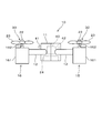
- FIG. 1 is a schematic diagram showing a flying device according to the first embodiment.
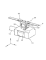
- FIG. 2 is a schematic view seen from the direction of arrow II in FIG.
- FIG. 3 is a schematic perspective view showing an example of the pitch changing mechanism of the flying device according to the first embodiment.
- FIG. 4 is a cross-sectional view showing the propeller of the flying device according to the first embodiment
- FIG. 5 is a cross-sectional view showing the propeller of the flying device according to the first embodiment
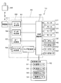
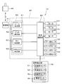
- FIG. 6 is a block diagram showing the configuration of the flying device according to the first embodiment.
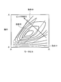
- FIG. 7 is a schematic diagram showing the relationship between the motor output, the pitch angle, and the lift force
- FIG. 8 is a schematic diagram showing the efficiency per unit output of the motor from the relationship between the motor output, lift and pitch angle
- FIG. 9 is a block diagram showing the configuration of the flying device according to the second embodiment.
- FIG. 10 is a block diagram showing the configuration of the flying device according to the third embodiment.
- FIG. 11 is a block diagram showing a configuration of a flying device according to the fourth embodiment.
- FIG. 12 is a block diagram showing the configuration of the flying device according to the fifth embodiment.
- the flying device 10 includes a base 11, an arm 12, a thruster 13, a thruster 14, a thruster 15, and a thruster 16.
- the base 11 is provided at the center of gravity of the flying device 10.
- the arm portion 12 extends radially outward from the base body 11.
- the thrusters 13 to 16 are provided at the tip of the arm portion 12, that is, the end portion of the arm portion 12 opposite to the base body 11, respectively.
- the four arm portions 12 extend symmetrically across the base body 11.
- the number of the arm portions 12 and the thrusters 13 to 16 is not limited to four, and can be set to an arbitrary number as long as it is four or more. Further, when the number of arms and thrusters is an odd number, it is not necessary to arrange them symmetrically across the base 11.
- the thruster 13 has a motor 131.
- the thruster 14 has a motor 141
- the thruster 15 has a motor 151
- the thruster 16 has a motor 161.
- the thrusters 13 to 16 each have a drive shaft member 22 and a propeller 23.
- Motors 131, 141, 151, and 161 are driving sources that drive the propeller 23, and use, for example, a battery 24 accommodated in the base 11 as a power source.
- the drive shaft member 22 transmits the rotation of the motors 131, 141, 151, 161 to the propeller 23.
- the propeller 23 extends radially outward from the drive shaft member 22.
- Each of the plurality of thrusters 13 to 16 has a pitch changing mechanism section 30.
- the pitch changing mechanism 30 includes a lever member 32, a link member 33, and a changing member 34.
- the pitch changing mechanism unit 30 changes the pitch of the propeller 23.
- the pitch changing mechanism unit 30 includes a servo motor 132 that generates a driving force for changing the pitch of the propeller 23.
- the pitch changing mechanism unit 30 has a servo motor 142.
- the pitch changing mechanism unit 30 has a servo motor 152.
- the pitch changing mechanism unit 30 has a servo motor 162.
- the rotation of the servo motor 132 is transmitted to the propeller 23 through the lever member 32, the link member 33, and the changing member 34.
- the rotation of the servo motor 132 is converted into the rotation of the propeller 23 about the propeller axis P perpendicular to the drive shaft member 22 through the lever member 32, the link member 33, and the changing member 34. That is, when the servo motor 132 rotates, the propeller 23 provided at the tip of the drive shaft member 22 rotates around the propeller shaft P.
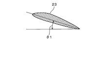
- the propeller 23 changes between the pitch angle ⁇ 1 that generates the thrust at the time of rising shown in FIG.
- An intermediate position between the pitch angle ⁇ 1 and the pitch angle 2 of the propeller 23 is a neutral position where no propulsive force is generated even when the propeller 23 rotates.
- the pitch of the propeller 23 changes from the pitch angle ⁇ ⁇ b> 2 toward the pitch angle ⁇ ⁇ b> 1
- the pitch of the propeller 23 changes to the plus side where the upward driving force increases.
- the pitch of the propeller 23 changes from the pitch angle ⁇ 1 toward the pitch angle ⁇ 2
- the pitch of the propeller 23 changes to the minus side where the propulsive force in the descending direction increases.
- the amount of change in the pitch of the propeller 23 corresponds to the rotation angle of the servo motors 132, 142, 152, 162.
- the flying device 10 includes a control unit 40, a reception unit 41, and an attitude detection unit 42.
- the control unit 40 is accommodated in the base 11 and connected to the battery 24.
- the control unit 40 has a synthesis calculation unit 43 as shown in FIG.
- the composition calculation unit 43 is configured around a microcomputer having a CPU, a ROM, and a RAM, and controls the entire flying device 10. That is, the control unit 40 corresponds to a control unit.
- the control unit 40 may be realized by hardware by an electric or electronic circuit, may be realized by software by executing a computer program, or may be realized by cooperation of hardware and software. May be.
- the receiving unit 41 is connected to the control unit 40.
- the receiving unit 41 receives a signal transmitted from a transmitting unit 44 provided separately from the base 11, that is, separately from the flying device 10.
- the transmission unit 44 is operated by the operator of the flying device 10, and the attitude and motion instructions of the base body 11 are input as flight instructions from the operator.
- the transmission unit 44 transmits the input flight instruction to the reception unit 41 connected wirelessly.
- the receiving unit 41 receives the flight instruction transmitted from the transmitting unit 44 and provides it to the control unit 40.
- the control unit 40 is connected to the motor of each thruster. That is, the control unit 40 is connected to the motor 131 of the thruster 13, the motor 141 of the thruster 14, the motor 151 of the thruster 15, and the motor 161 of the thruster 16.
- the control unit 40 outputs a motor output value for controlling the output change to the motor of each thruster.
- the control unit 40 is connected to the servo motor of each thruster. That is, the control unit 40 is connected to the servo motor 132 of the thruster 13, the servo motor 142 of the thruster 14, the servo motor 152 of the thruster 15, and the servo motor 162 of the thruster 16.
- the control unit 40 outputs a servo output value for controlling the driving of the servo motor that changes the pitch of the propeller 23 to the servo motor of each thruster.
- the attitude detection unit 42 detects the attitude of the flying device 10 from the tilt of the base 11 and the acceleration applied to the base 11.
- the posture detection unit 42 is connected to the acceleration sensor 51, the angular velocity sensor 52, the geomagnetic sensor 53, and the altitude sensor 54.
- the acceleration sensor 51 detects accelerations in three three-dimensional directions of the x axis, the y axis, and the z axis.
- the angular velocity sensor 52 detects angular velocities in three-dimensional three axial directions.
- the geomagnetic sensor 53 detects the geomagnetism in the three-dimensional three axial directions.
- the altitude sensor 54 detects the altitude in one axial direction in the vertical direction from, for example, a change in atmospheric pressure.
- the posture detection unit 42 determines the roll axis and pitch axis of the flying device 10 based on the acceleration detected by the acceleration sensor 51, the angular velocity detected by the angular velocity sensor 52, the geomagnetism detected by the geomagnetic sensor 53, and the altitude detected by the altitude sensor 54. , And the three-dimensional flight attitude with the yaw axis as the central axis, and the flight altitude of the flying device 10 are detected.
- the attitude detection unit 42 outputs the detected flight attitude and flight altitude of the flying device 10 to the control unit 40.
- the flight attitude and flight altitude detection processing in the attitude detector 42 may be realized in software by execution of a computer program by the control unit 40, realized in hardware by an electronic circuit, or software and hardware. It may be realized in cooperation.
- the control unit 40 has a determination unit 60 that determines a control value.
- the determination unit 60 includes a roll determination unit 61, a pitch determination unit 62, a yaw determination unit 63, and a throttle determination unit 64.
- the roll determination unit 61 determines a control value for PID control of the flying posture of the base body 11 with the roll axis as the central axis. Specifically, the roll determination unit 61 uses the roll input value related to the flight posture of the base body 11 centered on the roll axis included in the flight instruction received by the reception unit 41 and the roll axis detected by the posture detection unit 42.
- the roll control value is determined from the roll detection value of the flying posture of the base body 11 as the central axis.
- the pitch determination unit 62 determines a control value for performing PID control of the flying posture of the base body 11 with the pitch axis as the central axis. Specifically, the pitch determination unit 62 uses the pitch input value related to the flight posture of the base body 11 centered on the pitch axis included in the flight instruction received by the reception unit 41 and the pitch axis detected by the posture detection unit 42. The pitch control value is determined from the pitch detection value of the flying posture of the base body 11 as the central axis.
- the yaw determination unit 63 determines a control value for performing PID control of the flying posture of the base body 11 with the yaw axis as the central axis. Specifically, the yaw determination unit 63 uses the yaw input value related to the flight posture of the base body 11 centered on the yaw axis included in the flight instruction received by the reception unit 41 and the yaw axis detected by the posture detection unit 42. The yaw control value is determined from the yaw detection value relating to the flight posture of the base body 11 as the central axis.
- the throttle determining unit 64 determines a control value for PID control of the outputs of the motors 131, 141, 151, 161 in the thrusters 13-16. Specifically, the throttle determining unit 64 uses the throttle input value related to the flight altitude and flight speed included in the flight instruction received by the receiving unit 41, and the flight altitude and flight speed of the base body 11 detected by the attitude detection unit 42. Determine the throttle control value. In this case, the throttle determining unit 64 determines the throttle control value using the map stored in the map storage unit 71 included in the control unit 40.
- the composition calculator 43 determines the roll control value determined by the roll determiner 61, the pitch control value determined by the pitch determiner 62, the yaw control value determined by the yaw determiner 63, and the throttle determiner 64.
- the throttle control value is synthesized. That is, the composition calculation unit 43 combines the roll control value, the pitch control value, the yaw control value, and the throttle control value, and outputs the motor output values to be output to the motors 131, 141, 151, 161 of the thrusters 13-16, and Servo output values to be output to the servo motors 132, 142, 152, 162 of the thrusters 13-16 are generated.
- the combination calculation unit 43 generates a motor output value to be output to the motors 131, 141, 151, 161 and a servo output value to be output to the servo motors 132, 142, 152, 162 as in the following control expression.
- control unit 40 controls the rotation about the pitch axis of the flying device 10 and the rotation about the roll axis of the flying device 10 using the servo motors 132, 142, 152, 162. To do. That is, the control unit 40 controls the rotation about the pitch axis and the roll axis as the center axis by changing the pitch of the propeller 23 by the servo motors 132, 142, 152, 162. Further, the control unit 40 controls the rotation of the flying device 10 around the yaw axis as a central axis using the motors 131, 141, 151, and 161.
- control unit 40 controls rotation about the yaw axis as a center axis by changing the output of the motors 131, 141, 151, 161, that is, the number of rotations.
- the control unit 40 controls the flying of the flying device 10 along the throttle, that is, the yaw axis, and the speed change using the motors 131, 141, 151, 161 and the servo motors 132, 142, 152, 162. To do.
- control unit 40 changes the output of the motors 131, 141, 151, 161, that is, the rotational speed, and the pitch angle of the propeller 23 by the servo motors 132, 142, 152, 162 with respect to the ascent and descent of the flying device 10. And control using both.
- the control unit 40 controls not only the outputs of the motors 131, 141, 151 and 161 in the thrusters 13 to 16, but also the pitch angle of the propeller 23.
- the flying device 10 quickly changes the flight posture and the flight altitude according to the flight instruction transmitted from the transmission unit 44, and also responds quickly to a sudden change in flight posture due to disturbance. Stabilize posture.
- control unit 40 changes the pitch angle of the propeller 23 by the servo motors 132, 142, 152, 162 when controlling the rotation about the pitch axis and the roll axis of the base 11 as the central axis. I have control.
- control unit 40 controls the rotation of the base body 11 by changing the outputs of the motors 131, 141, 151, 161 when controlling the rotation of the base 11 about the yaw axis.
- control unit 40 controls the rotation of the base 11 with the pitch axis, roll axis, or yaw axis as the central axis
- any of the motors 131, 141, 151, 161 or the servo motors 132, 142, 152, 162 is selected. Only one of them needs to be controlled. Therefore, the control unit 40 can simplify the control of the thrusters 13 to 16 when changing the posture of the base 11.
- control unit 40 controls the motors 131, 141, 151, 161 and the servo motors 132, 142, 152 in each thruster 13-16 when controlling the rise and fall along the throttle, that is, the yaw axis, and the change in speed. 162 is controlled in combination. That is, the control unit 40 adds or subtracts the throttle control value by referring to the map stored in the map storage unit 71 as in the above control equation, and outputs the motor to the motors 131, 141, 151, 161. The output value and the servo output value to be output to the servo motors 132, 142, 152, 162 are generated. As shown in FIG.
- the map stored in the map storage unit 71 generates the outputs of the motors 131, 141, 151, 161 in the thrusters 13-16, the pitch angle of the propeller 23, and the thrusters 13-16. It is set based on the relationship with lift. That is, as the output of the motors 131, 141, 151, 161 in the thrusters 13-16, that is, the rotational speed of the motors 131, 141, 151, 161 increases, the lift generated by the thrusters 13-16 increases. Similarly, as the pitch angle of the propeller 23 in each thruster 13-16 increases to the plus side, the lift generated by each thruster 13-16 increases. However, when the pitch angle of the propeller 23 becomes excessive, the propeller 23 stalls.
- the motor output value and the servo output value are set in the map stored in the map storage unit 71 so that a large lift can be efficiently obtained within a range where the pitch angle of the propeller 23 is not excessive.
- the control unit 40 sets the motor output value and the servo output value so that a large lift can be obtained from the map stored in the map storage unit 71 within a range where the pitch angle of the propeller 23 is not excessive. Thereby, the flying device 10 can achieve a rapid change in altitude or speed.
- the control unit 40 when the flying device 10 changes the flight attitude and the flight altitude, the control unit 40 mainly uses the outputs of the motors 131, 141, 151, 161 of the thrusters 13 to 16 as the flight attitude and the flight altitude. And the flight attitude and the flight altitude are finely adjusted by the pitch angle of the propeller 23. When changing the flight attitude or the flight altitude, the responsiveness from the input of the flight instruction for the change until the output of the motors 131, 141, 151, 161 changes is not high.
- the control unit 40 maintains the altitude of the flying device 10, that is, when there is no significant change in the flight posture or the flight altitude as in hovering, the change in the output of the motors 131, 141, 151, 161 is reduced.
- the flight attitude and the flight altitude are controlled by changing the pitch angle of the propeller 23.
- the control unit 40 increases the output of the motors 131, 141, 151, 161 in addition to the change in the pitch angle of the propeller 23, and generates lift. Increase the change of
- the map stored in the map storage unit 71 is based on the relationship among the outputs of the motors 131, 141, 151, 161, the pitch angle of the propeller 23, and the lift per unit output as shown in FIG. It may be set. That is, as the output of the motors 131, 141, 151, 161 in the thrusters 13-16, that is, the rotational speed of the motors 131, 141, 151, 161 increases, the lift generated by the thrusters 13-16 increases. On the other hand, when the outputs of the motors 131, 141, 151, 161 increase, the power consumed by the motors 131, 141, 151, 161 also increases.
- the control unit 40 selects the number of rotations of the motors 131, 141, 151, 161 and the pitch angle of the propeller 23 that increase the lift per unit output from the map stored in the map storage unit 71, and outputs the motor output. Set the value and servo output value. Thereby, if the capacity
- the map stored in the map storage unit 71 sets the outputs of the motors 131, 141, 151, 161 to be low, and the change of the pitch angle of the propeller 23 causes the flight device 10 to You may set so that a raise and a fall may be controlled.
- the outputs of the motors 131, 141, 151, and 161 are suppressed, the rotational speed of the motors 131, 141, 151, and 161 can be reduced, and noise and vibration can be reduced.
- the control unit 40 changes the pitch of the propeller 23 as well as the outputs of the motors 131, 141, 151, 161 of the thrusters 13 to 16 to change the flying device 10. Controlling the flight attitude and flight altitude. That is, the plurality of thrusters 13 to 16 have a pitch changing mechanism unit 30 that changes the pitch of the propeller 23. Thereby, when controlling the attitude
- the pitch of the propeller 23 By changing the pitch of the propeller 23, the propulsive force generated by the thrusters 13 to 16 changes more rapidly than in the case where the rotational speeds of the motors 131, 141, 151, and 161 are changed.
- the control unit 40 quickly changes the attitude of the base body 11 To control. Therefore, the responsiveness of the posture change can be improved, and the flight posture can be quickly stabilized.
- the control unit 40 changes the flight attitude and the flight altitude mainly by the outputs of the motors 131, 141, 151, 161 of the thrusters 13-16.
- the flight attitude and the flight altitude are finely adjusted by the pitch angle of the propeller 23.
- control unit 40 maintains the altitude of the flying device 10, that is, when there is no significant change in the flight posture or the flight altitude as in hovering, the change in the output of the motors 131, 141, 151, 161 is reduced.
- the flight attitude and the flight altitude are controlled by changing the pitch angle of the propeller 23. Therefore, it is possible to quickly maintain the flight posture and the flight altitude while reducing the influence of disturbance.
- the control unit 40 controls the rotation of the flying device 10 around the roll axis or the pitch axis as the central axis
- the outputs of the servo motors 132, 142, 152, 162 of the thrusters 13-16 are output.
- the control unit 40 controls the flight attitude only by changing the pitch by changing the servo motor output value.
- the control unit 40 controls the outputs of the motors 131, 141, 151, 161 of the thrusters 13-16 when controlling the rotation of the flying device 10 with the yaw axis as the central axis. That is, when the flying device 10 changes the flight posture with the yaw axis as the central axis, the control unit 40 controls the flight posture only by the motor output value. Therefore, it is possible to simplify the control accompanying the change of the flight posture.
- the control unit 40 moves the flying device 10 in the yaw axis direction, that is, when accompanied by a change in altitude such as ascending and descending or a change in speed, the motors 131, 141, 151 of the thrusters 13-16. , 161 and the pitch angle of the propeller 23 are changed. That is, the control unit 40 sets the motor output value and the servo output value so that a large lift can be obtained from the map stored in the map storage unit 71 within a range where the pitch angle of the propeller 23 is not excessive. Therefore, rapid altitude change and speed change of the flying device 10 can be achieved.
- the control unit 40 causes the motors 131, 141, and 151 to increase the lift per unit output, that is, per 1 kW of power consumption. , 161 and the pitch angle of the propeller 23 are selected. As a result, the power consumption efficiency of each of the thrusters 13 to 16 is improved. Therefore, if the capacity of the battery 24 is constant, the flight time can be extended.
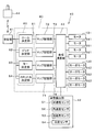
- FIG. 9 shows the configuration of the flying device according to the second embodiment.
- the control unit 40 does not have a map storage unit that stores a map. That is, the control unit 40 controls the flight altitude and the flight speed only by the outputs of the motors 131, 141, 151, and 161 with respect to the throttle input value relating to the change of the flight altitude and the flight speed.
- the control unit 40 generates a motor output value and a servo output value by the following control expression.
- the servo output value does not refer to the throttle control value and the map storage unit map.
- the flying device 10 when used inside a structure such as a room or a tunnel, it is not easily affected by disturbances such as wind.
- disturbances such as wind.
- control that refers to the map that calculates the efficiency for the control of the flight altitude and the flight speed is omitted as described above, the flight attitude and the flight altitude are hardly changed. . Therefore, in the second embodiment, control can be optimized in an environment that is not easily affected by disturbance.
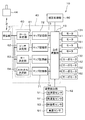
- FIGS. 10 and 11 The configurations of the flying devices according to the third embodiment and the fourth embodiment are shown in FIGS. 10 and 11, respectively.
- the control unit 40 controls the motors 131, 141, and the like in the thrusters 13 to 16 for the rotation control with the roll axis as the central axis and the rotation control with the pitch axis as the central axis.
- the outputs 151 and 161 and the pitch angle of the propeller 23 are controlled. That is, the control unit 40 includes not only a map storage unit 71 that stores a map for the throttle control value, but also a map storage unit 72 and a map storage unit 73.
- the map storage unit 72 stores a map of the output of the motors 131, 141, 151, 161 and the pitch angle of the propeller 23 with respect to the roll control value. Further, the map storage unit 73 stores a map of the outputs of the motors 131, 141, 151, and 161 and the pitch angle of the propeller 23 with respect to the pitch control value. Thereby, the control unit 40 sets a motor output value and a servo output value based on the following control expression.
- the control unit 40 controls the rotation of the thrusters 13 to 16 motors 131, 141, 151, 161 in addition to the configuration of the third embodiment. And the pitch angle of the propeller 23 are controlled. That is, the control unit 40 further includes a map storage unit 74.
- the map storage unit 74 stores a map of outputs of the motors 131, 141, 151, 161 and the pitch angle of the propeller 23 with respect to the yaw control value. Thereby, the control unit 40 sets a motor output value and a servo output value based on the following control expression.
- both the output of the motors 131, 141, 151, and 161 and the pitch angle of the propeller 23 are controlled with respect to the rotation about the roll axis and the pitch axis.
- both the outputs of the motors 131, 141, 151, 161 and the pitch angle of the propeller 23 are controlled.
- the outputs of the motors 131, 141, 151, 161 and the pitch angle of the propeller 23 are controlled in cooperation with respect to many shafts. For this reason, for example, a large change in posture caused by contact with an obstacle is quickly dealt with. Therefore, more stable flight can be continued.
- FIG. 12 shows the configuration of the flying device according to the fifth embodiment.
- the fifth embodiment shown in FIG. 12 is a modification of the fourth embodiment, and the control unit 40 is connected to the correction processing unit 80.
- the correction processing unit 80 adds a correction term and a recovery term to the control expression generated by the synthesis calculation unit 43.
- the correction processing unit 80 is realized by software, hardware, or cooperation between software and hardware.
- the correction term is a term added by learning a change in performance over time, such as deterioration over time of the motors 131, 141, 151, 161, for example.
- the correction processing unit 80 changes the motor output value and the servo output value by adding this correction term to the control expression.
- the recovery term is normally set to “0”.
- the recovery term is set so as to be lift that causes a gentle descent by changing the outputs of the motors 131, 141, 151, 161.
- the recovery term is set to a pitch angle that causes a gentle descent using the rotation due to inertia of the motors 131, 141, 151, 161. Is done.
- the control unit 40 generates a motor output value and a servo output value with the following control equations.
- correction terms and recovery terms are added to cope with changes in the characteristics and abnormalities of the motors 131, 141, 151, 161 and servo motors 132, 142, 152, 162 over time. is doing. Therefore, it is possible to maintain a stable flight posture over a long period of time and improve safety.
- the example in which the correction term and the recovery term are added as a modification of the fourth embodiment has been described.
- the correction term and the recovery term are added to the first to third embodiments described above. Also good.
Abstract
Selon l'invention, lorsqu'un dispositif de vol 10 change d'attitude et d'altitude de vol, une unité de commande 40 change l'attitude et l'altitude de vol en utilisant principalement les sorties des moteurs 131, 141, 151, 161 de chaque propulseur 13 à 16, et règle finement l'attitude et l'altitude de vol en utilisant les angles de pas des hélices 23. Lorsque l'altitude du dispositif de vol 10 est maintenue, c'est-à-dire lorsqu'il n'y a pas de changements significatifs de l'attitude et de l'altitude de vol telles que pendant le vol stationnaire, l'unité de commande 40 commande l'attitude et l'altitude de vol par changement des angles de pas des hélices 23, tout en réduisant les changements aux sorties des moteurs 131, 141, 151, 161.
Applications Claiming Priority (2)
| Application Number | Priority Date | Filing Date | Title |
|---|---|---|---|
| JP2016161947A JP6603186B2 (ja) | 2016-08-22 | 2016-08-22 | 飛行装置 |
| JP2016-161947 | 2016-08-22 |
Publications (1)
| Publication Number | Publication Date |
|---|---|
| WO2018037795A1 true WO2018037795A1 (fr) | 2018-03-01 |
Family
ID=61245605
Family Applications (1)
| Application Number | Title | Priority Date | Filing Date |
|---|---|---|---|
| PCT/JP2017/026503 WO2018037795A1 (fr) | 2016-08-22 | 2017-07-21 | Dispositif de vol |
Country Status (2)
| Country | Link |
|---|---|
| JP (1) | JP6603186B2 (fr) |
| WO (1) | WO2018037795A1 (fr) |
Cited By (5)
| Publication number | Priority date | Publication date | Assignee | Title |
|---|---|---|---|---|
| CN109334962A (zh) * | 2018-09-29 | 2019-02-15 | 江苏师范大学 | 一种无人机式紧急物品精准投送装置 |
| WO2021125607A1 (fr) * | 2019-12-20 | 2021-06-24 | 한국항공우주연구원 | Système permettant de commander le nombre de tours par minute de l'hélice et du rotor d'un véhicule aérien ayant de multiples dispositifs de puissance |
| CN113240881A (zh) * | 2021-07-12 | 2021-08-10 | 环球数科集团有限公司 | 一种基于多特征融合的火灾识别系统 |
| CN114313220A (zh) * | 2021-12-20 | 2022-04-12 | 中国航天空气动力技术研究院 | 一种冗余设计的螺旋桨桨距角精确控制装置及方法 |
| US11649037B2 (en) * | 2019-03-15 | 2023-05-16 | The Boeing Company | Low latency pitch adjustable rotors |
Families Citing this family (1)
| Publication number | Priority date | Publication date | Assignee | Title |
|---|---|---|---|---|
| US11117657B2 (en) * | 2018-01-19 | 2021-09-14 | Aerhart, LLC | Aeronautical apparatus |
Citations (2)
| Publication number | Priority date | Publication date | Assignee | Title |
|---|---|---|---|---|
| JP2005289127A (ja) * | 2004-03-31 | 2005-10-20 | Nagasaki Prefecture | 飛行装置の姿勢位置制御システムおよび姿勢位置制御装置 |
| JP2016049900A (ja) * | 2014-09-01 | 2016-04-11 | 国立大学法人 東京大学 | 飛行装置 |
Family Cites Families (2)
| Publication number | Priority date | Publication date | Assignee | Title |
|---|---|---|---|---|
| JP4537121B2 (ja) * | 2004-06-08 | 2010-09-01 | 富士重工業株式会社 | 回転翼航空機の高度制御装置 |
| KR101658386B1 (ko) * | 2015-01-28 | 2016-09-21 | 조선대학교산학협력단 | 추력 조절기 및 그 추력 조절기를 포함하는 멀티콥터 |
-
2016
- 2016-08-22 JP JP2016161947A patent/JP6603186B2/ja active Active
-
2017
- 2017-07-21 WO PCT/JP2017/026503 patent/WO2018037795A1/fr active Application Filing
Patent Citations (2)
| Publication number | Priority date | Publication date | Assignee | Title |
|---|---|---|---|---|
| JP2005289127A (ja) * | 2004-03-31 | 2005-10-20 | Nagasaki Prefecture | 飛行装置の姿勢位置制御システムおよび姿勢位置制御装置 |
| JP2016049900A (ja) * | 2014-09-01 | 2016-04-11 | 国立大学法人 東京大学 | 飛行装置 |
Cited By (5)
| Publication number | Priority date | Publication date | Assignee | Title |
|---|---|---|---|---|
| CN109334962A (zh) * | 2018-09-29 | 2019-02-15 | 江苏师范大学 | 一种无人机式紧急物品精准投送装置 |
| US11649037B2 (en) * | 2019-03-15 | 2023-05-16 | The Boeing Company | Low latency pitch adjustable rotors |
| WO2021125607A1 (fr) * | 2019-12-20 | 2021-06-24 | 한국항공우주연구원 | Système permettant de commander le nombre de tours par minute de l'hélice et du rotor d'un véhicule aérien ayant de multiples dispositifs de puissance |
| CN113240881A (zh) * | 2021-07-12 | 2021-08-10 | 环球数科集团有限公司 | 一种基于多特征融合的火灾识别系统 |
| CN114313220A (zh) * | 2021-12-20 | 2022-04-12 | 中国航天空气动力技术研究院 | 一种冗余设计的螺旋桨桨距角精确控制装置及方法 |
Also Published As
| Publication number | Publication date |
|---|---|
| JP2018030384A (ja) | 2018-03-01 |
| JP6603186B2 (ja) | 2019-11-06 |
Similar Documents
| Publication | Publication Date | Title |
|---|---|---|
| JP6603186B2 (ja) | 飛行装置 | |
| JP6557883B2 (ja) | 飛行装置 | |
| EP3927618B1 (fr) | Véhicule aérien sans pilote dotée d'une propulsion tolérante aux collisions et d'un organe de commande | |
| JP2017109603A (ja) | 飛行装置 | |
| JP6456641B2 (ja) | マルチロータクラフトの姿勢安定化制御装置 | |
| KR100351378B1 (ko) | 이동체의 조종장치 | |
| JP6229184B2 (ja) | 飛行体および飛行体の制御方法 | |
| JP2018144732A (ja) | 飛行装置 | |
| JP2016135660A (ja) | 飛行体 | |
| JP6905401B2 (ja) | 飛行装置 | |
| JP2016135659A (ja) | 飛行体 | |
| CN112292317A (zh) | 飞行体以及飞行体的控制方法 | |
| JP2014046425A (ja) | 駆動装置 | |
| KR101622277B1 (ko) | 모듈화된 쿼드 로터 제어 시스템 및 그의 제어 방법 | |
| EP3640135A1 (fr) | Dispositif volant | |
| JP2021041755A (ja) | 飛行装置 | |
| CN109991990B (zh) | 带旋转云台的多平行控制力矩陀螺的平衡装置及控制方法 | |
| JP2020111076A (ja) | スラスタ制御装置および姿勢制御装置 | |
| WO2018037796A1 (fr) | Dispositif de vol | |
| JP2020040664A (ja) | プロペラ、モータ部品及びこれを備えた飛行体 | |
| JP7139229B2 (ja) | 遠隔制御ヘリコプタの駆動制御装置 | |
| US10259575B2 (en) | Feed-forward compensation for gyroscopic loads in a coaxial rotor | |
| Derafa et al. | Four Rotors Helicopter Yaw and Altitude Stabilization. | |
| JP6922370B2 (ja) | 飛行体 | |
| WO2018024915A1 (fr) | Véhicule sans pilote |
Legal Events
| Date | Code | Title | Description |
|---|---|---|---|
| 121 | Ep: the epo has been informed by wipo that ep was designated in this application |
Ref document number: 17843281 Country of ref document: EP Kind code of ref document: A1 |
|
| NENP | Non-entry into the national phase |
Ref country code: DE |
|
| 122 | Ep: pct application non-entry in european phase |
Ref document number: 17843281 Country of ref document: EP Kind code of ref document: A1 |