WO2018037795A1 - Flight device - Google Patents
Flight device Download PDFInfo
- Publication number
- WO2018037795A1 WO2018037795A1 PCT/JP2017/026503 JP2017026503W WO2018037795A1 WO 2018037795 A1 WO2018037795 A1 WO 2018037795A1 JP 2017026503 W JP2017026503 W JP 2017026503W WO 2018037795 A1 WO2018037795 A1 WO 2018037795A1
- Authority
- WO
- WIPO (PCT)
- Prior art keywords
- pid
- pitch
- motor
- output
- flight
- Prior art date
Links
- 238000001514 detection method Methods 0.000 claims description 16
- 239000000758 substrate Substances 0.000 claims description 6
- 238000011084 recovery Methods 0.000 description 10
- 238000010586 diagram Methods 0.000 description 8
- 230000001133 acceleration Effects 0.000 description 6
- 238000004364 calculation method Methods 0.000 description 5
- 230000004043 responsiveness Effects 0.000 description 5
- 206010034719 Personality change Diseases 0.000 description 4
- 230000005856 abnormality Effects 0.000 description 4
- 230000004048 modification Effects 0.000 description 4
- 238000012986 modification Methods 0.000 description 4
- 230000001141 propulsive effect Effects 0.000 description 4
- 230000005540 biological transmission Effects 0.000 description 3
- 230000015572 biosynthetic process Effects 0.000 description 2
- 238000004590 computer program Methods 0.000 description 2
- 238000000034 method Methods 0.000 description 2
- 238000003786 synthesis reaction Methods 0.000 description 2
- 230000001174 ascending effect Effects 0.000 description 1
- 230000006866 deterioration Effects 0.000 description 1
- 230000005484 gravity Effects 0.000 description 1
- 230000007935 neutral effect Effects 0.000 description 1
- 230000000630 rising effect Effects 0.000 description 1
Images


Classifications
-
- B—PERFORMING OPERATIONS; TRANSPORTING
- B64—AIRCRAFT; AVIATION; COSMONAUTICS
- B64U—UNMANNED AERIAL VEHICLES [UAV]; EQUIPMENT THEREFOR
- B64U50/00—Propulsion; Power supply
- B64U50/20—Transmission of mechanical power to rotors or propellers
- B64U50/23—Transmission of mechanical power to rotors or propellers with each propulsion means having an individual motor
-
- B—PERFORMING OPERATIONS; TRANSPORTING
- B64—AIRCRAFT; AVIATION; COSMONAUTICS
- B64C—AEROPLANES; HELICOPTERS
- B64C11/00—Propellers, e.g. of ducted type; Features common to propellers and rotors for rotorcraft
- B64C11/02—Hub construction
- B64C11/04—Blade mountings
- B64C11/06—Blade mountings for variable-pitch blades
-
- B—PERFORMING OPERATIONS; TRANSPORTING
- B64—AIRCRAFT; AVIATION; COSMONAUTICS
- B64U—UNMANNED AERIAL VEHICLES [UAV]; EQUIPMENT THEREFOR
- B64U30/00—Means for producing lift; Empennages; Arrangements thereof
- B64U30/20—Rotors; Rotor supports
- B64U30/29—Constructional aspects of rotors or rotor supports; Arrangements thereof
- B64U30/296—Rotors with variable spatial positions relative to the UAV body
Definitions
- the present disclosure relates to a flying device.
- Such a flight apparatus includes a plurality of thrusters each including a propeller and a motor.
- the flying device controls the number of rotations of the motor to move up and down in the yaw axis direction, rotational motion about the yaw axis, and rotational motion about the pitch axis and roll axis. Control each.
- an object of the present disclosure is to provide a flying device that has high attitude change responsiveness and can quickly stabilize the flying attitude.
- the plurality of thrusters have a pitch changing mechanism that changes the pitch of the propeller.
- the control unit changes not only the motor output but also the propeller pitch when controlling the posture of the base.
- the pitch of the propeller By changing the pitch of the propeller, the propulsive force generated by the thruster changes more quickly than when the number of rotations of the motor is changed.
- the control unit quickly controls the attitude of the base body. Therefore, the responsiveness of the posture change can be improved, and the flight posture can be quickly stabilized.
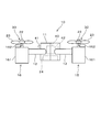
- FIG. 1 is a schematic diagram showing a flying device according to the first embodiment.
- FIG. 2 is a schematic view seen from the direction of arrow II in FIG.
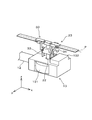
- FIG. 3 is a schematic perspective view showing an example of the pitch changing mechanism of the flying device according to the first embodiment.
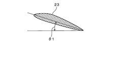
- FIG. 4 is a cross-sectional view showing the propeller of the flying device according to the first embodiment
- FIG. 5 is a cross-sectional view showing the propeller of the flying device according to the first embodiment
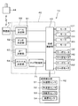
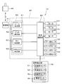
- FIG. 6 is a block diagram showing the configuration of the flying device according to the first embodiment.
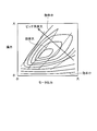
- FIG. 7 is a schematic diagram showing the relationship between the motor output, the pitch angle, and the lift force
- FIG. 8 is a schematic diagram showing the efficiency per unit output of the motor from the relationship between the motor output, lift and pitch angle
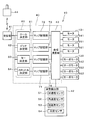
- FIG. 9 is a block diagram showing the configuration of the flying device according to the second embodiment.
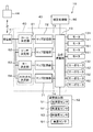
- FIG. 10 is a block diagram showing the configuration of the flying device according to the third embodiment.
- FIG. 11 is a block diagram showing a configuration of a flying device according to the fourth embodiment.
- FIG. 12 is a block diagram showing the configuration of the flying device according to the fifth embodiment.
- the flying device 10 includes a base 11, an arm 12, a thruster 13, a thruster 14, a thruster 15, and a thruster 16.
- the base 11 is provided at the center of gravity of the flying device 10.
- the arm portion 12 extends radially outward from the base body 11.
- the thrusters 13 to 16 are provided at the tip of the arm portion 12, that is, the end portion of the arm portion 12 opposite to the base body 11, respectively.
- the four arm portions 12 extend symmetrically across the base body 11.
- the number of the arm portions 12 and the thrusters 13 to 16 is not limited to four, and can be set to an arbitrary number as long as it is four or more. Further, when the number of arms and thrusters is an odd number, it is not necessary to arrange them symmetrically across the base 11.
- the thruster 13 has a motor 131.
- the thruster 14 has a motor 141
- the thruster 15 has a motor 151
- the thruster 16 has a motor 161.
- the thrusters 13 to 16 each have a drive shaft member 22 and a propeller 23.
- Motors 131, 141, 151, and 161 are driving sources that drive the propeller 23, and use, for example, a battery 24 accommodated in the base 11 as a power source.
- the drive shaft member 22 transmits the rotation of the motors 131, 141, 151, 161 to the propeller 23.
- the propeller 23 extends radially outward from the drive shaft member 22.
- Each of the plurality of thrusters 13 to 16 has a pitch changing mechanism section 30.
- the pitch changing mechanism 30 includes a lever member 32, a link member 33, and a changing member 34.
- the pitch changing mechanism unit 30 changes the pitch of the propeller 23.
- the pitch changing mechanism unit 30 includes a servo motor 132 that generates a driving force for changing the pitch of the propeller 23.
- the pitch changing mechanism unit 30 has a servo motor 142.
- the pitch changing mechanism unit 30 has a servo motor 152.
- the pitch changing mechanism unit 30 has a servo motor 162.
- the rotation of the servo motor 132 is transmitted to the propeller 23 through the lever member 32, the link member 33, and the changing member 34.
- the rotation of the servo motor 132 is converted into the rotation of the propeller 23 about the propeller axis P perpendicular to the drive shaft member 22 through the lever member 32, the link member 33, and the changing member 34. That is, when the servo motor 132 rotates, the propeller 23 provided at the tip of the drive shaft member 22 rotates around the propeller shaft P.
- the propeller 23 changes between the pitch angle ⁇ 1 that generates the thrust at the time of rising shown in FIG.
- An intermediate position between the pitch angle ⁇ 1 and the pitch angle 2 of the propeller 23 is a neutral position where no propulsive force is generated even when the propeller 23 rotates.
- the pitch of the propeller 23 changes from the pitch angle ⁇ ⁇ b> 2 toward the pitch angle ⁇ ⁇ b> 1
- the pitch of the propeller 23 changes to the plus side where the upward driving force increases.
- the pitch of the propeller 23 changes from the pitch angle ⁇ 1 toward the pitch angle ⁇ 2
- the pitch of the propeller 23 changes to the minus side where the propulsive force in the descending direction increases.
- the amount of change in the pitch of the propeller 23 corresponds to the rotation angle of the servo motors 132, 142, 152, 162.
- the flying device 10 includes a control unit 40, a reception unit 41, and an attitude detection unit 42.
- the control unit 40 is accommodated in the base 11 and connected to the battery 24.
- the control unit 40 has a synthesis calculation unit 43 as shown in FIG.
- the composition calculation unit 43 is configured around a microcomputer having a CPU, a ROM, and a RAM, and controls the entire flying device 10. That is, the control unit 40 corresponds to a control unit.
- the control unit 40 may be realized by hardware by an electric or electronic circuit, may be realized by software by executing a computer program, or may be realized by cooperation of hardware and software. May be.
- the receiving unit 41 is connected to the control unit 40.
- the receiving unit 41 receives a signal transmitted from a transmitting unit 44 provided separately from the base 11, that is, separately from the flying device 10.
- the transmission unit 44 is operated by the operator of the flying device 10, and the attitude and motion instructions of the base body 11 are input as flight instructions from the operator.
- the transmission unit 44 transmits the input flight instruction to the reception unit 41 connected wirelessly.
- the receiving unit 41 receives the flight instruction transmitted from the transmitting unit 44 and provides it to the control unit 40.
- the control unit 40 is connected to the motor of each thruster. That is, the control unit 40 is connected to the motor 131 of the thruster 13, the motor 141 of the thruster 14, the motor 151 of the thruster 15, and the motor 161 of the thruster 16.
- the control unit 40 outputs a motor output value for controlling the output change to the motor of each thruster.
- the control unit 40 is connected to the servo motor of each thruster. That is, the control unit 40 is connected to the servo motor 132 of the thruster 13, the servo motor 142 of the thruster 14, the servo motor 152 of the thruster 15, and the servo motor 162 of the thruster 16.
- the control unit 40 outputs a servo output value for controlling the driving of the servo motor that changes the pitch of the propeller 23 to the servo motor of each thruster.
- the attitude detection unit 42 detects the attitude of the flying device 10 from the tilt of the base 11 and the acceleration applied to the base 11.
- the posture detection unit 42 is connected to the acceleration sensor 51, the angular velocity sensor 52, the geomagnetic sensor 53, and the altitude sensor 54.
- the acceleration sensor 51 detects accelerations in three three-dimensional directions of the x axis, the y axis, and the z axis.
- the angular velocity sensor 52 detects angular velocities in three-dimensional three axial directions.
- the geomagnetic sensor 53 detects the geomagnetism in the three-dimensional three axial directions.
- the altitude sensor 54 detects the altitude in one axial direction in the vertical direction from, for example, a change in atmospheric pressure.
- the posture detection unit 42 determines the roll axis and pitch axis of the flying device 10 based on the acceleration detected by the acceleration sensor 51, the angular velocity detected by the angular velocity sensor 52, the geomagnetism detected by the geomagnetic sensor 53, and the altitude detected by the altitude sensor 54. , And the three-dimensional flight attitude with the yaw axis as the central axis, and the flight altitude of the flying device 10 are detected.
- the attitude detection unit 42 outputs the detected flight attitude and flight altitude of the flying device 10 to the control unit 40.
- the flight attitude and flight altitude detection processing in the attitude detector 42 may be realized in software by execution of a computer program by the control unit 40, realized in hardware by an electronic circuit, or software and hardware. It may be realized in cooperation.
- the control unit 40 has a determination unit 60 that determines a control value.
- the determination unit 60 includes a roll determination unit 61, a pitch determination unit 62, a yaw determination unit 63, and a throttle determination unit 64.
- the roll determination unit 61 determines a control value for PID control of the flying posture of the base body 11 with the roll axis as the central axis. Specifically, the roll determination unit 61 uses the roll input value related to the flight posture of the base body 11 centered on the roll axis included in the flight instruction received by the reception unit 41 and the roll axis detected by the posture detection unit 42.
- the roll control value is determined from the roll detection value of the flying posture of the base body 11 as the central axis.
- the pitch determination unit 62 determines a control value for performing PID control of the flying posture of the base body 11 with the pitch axis as the central axis. Specifically, the pitch determination unit 62 uses the pitch input value related to the flight posture of the base body 11 centered on the pitch axis included in the flight instruction received by the reception unit 41 and the pitch axis detected by the posture detection unit 42. The pitch control value is determined from the pitch detection value of the flying posture of the base body 11 as the central axis.
- the yaw determination unit 63 determines a control value for performing PID control of the flying posture of the base body 11 with the yaw axis as the central axis. Specifically, the yaw determination unit 63 uses the yaw input value related to the flight posture of the base body 11 centered on the yaw axis included in the flight instruction received by the reception unit 41 and the yaw axis detected by the posture detection unit 42. The yaw control value is determined from the yaw detection value relating to the flight posture of the base body 11 as the central axis.
- the throttle determining unit 64 determines a control value for PID control of the outputs of the motors 131, 141, 151, 161 in the thrusters 13-16. Specifically, the throttle determining unit 64 uses the throttle input value related to the flight altitude and flight speed included in the flight instruction received by the receiving unit 41, and the flight altitude and flight speed of the base body 11 detected by the attitude detection unit 42. Determine the throttle control value. In this case, the throttle determining unit 64 determines the throttle control value using the map stored in the map storage unit 71 included in the control unit 40.
- the composition calculator 43 determines the roll control value determined by the roll determiner 61, the pitch control value determined by the pitch determiner 62, the yaw control value determined by the yaw determiner 63, and the throttle determiner 64.
- the throttle control value is synthesized. That is, the composition calculation unit 43 combines the roll control value, the pitch control value, the yaw control value, and the throttle control value, and outputs the motor output values to be output to the motors 131, 141, 151, 161 of the thrusters 13-16, and Servo output values to be output to the servo motors 132, 142, 152, 162 of the thrusters 13-16 are generated.
- the combination calculation unit 43 generates a motor output value to be output to the motors 131, 141, 151, 161 and a servo output value to be output to the servo motors 132, 142, 152, 162 as in the following control expression.
- control unit 40 controls the rotation about the pitch axis of the flying device 10 and the rotation about the roll axis of the flying device 10 using the servo motors 132, 142, 152, 162. To do. That is, the control unit 40 controls the rotation about the pitch axis and the roll axis as the center axis by changing the pitch of the propeller 23 by the servo motors 132, 142, 152, 162. Further, the control unit 40 controls the rotation of the flying device 10 around the yaw axis as a central axis using the motors 131, 141, 151, and 161.
- control unit 40 controls rotation about the yaw axis as a center axis by changing the output of the motors 131, 141, 151, 161, that is, the number of rotations.
- the control unit 40 controls the flying of the flying device 10 along the throttle, that is, the yaw axis, and the speed change using the motors 131, 141, 151, 161 and the servo motors 132, 142, 152, 162. To do.
- control unit 40 changes the output of the motors 131, 141, 151, 161, that is, the rotational speed, and the pitch angle of the propeller 23 by the servo motors 132, 142, 152, 162 with respect to the ascent and descent of the flying device 10. And control using both.
- the control unit 40 controls not only the outputs of the motors 131, 141, 151 and 161 in the thrusters 13 to 16, but also the pitch angle of the propeller 23.
- the flying device 10 quickly changes the flight posture and the flight altitude according to the flight instruction transmitted from the transmission unit 44, and also responds quickly to a sudden change in flight posture due to disturbance. Stabilize posture.
- control unit 40 changes the pitch angle of the propeller 23 by the servo motors 132, 142, 152, 162 when controlling the rotation about the pitch axis and the roll axis of the base 11 as the central axis. I have control.
- control unit 40 controls the rotation of the base body 11 by changing the outputs of the motors 131, 141, 151, 161 when controlling the rotation of the base 11 about the yaw axis.
- control unit 40 controls the rotation of the base 11 with the pitch axis, roll axis, or yaw axis as the central axis
- any of the motors 131, 141, 151, 161 or the servo motors 132, 142, 152, 162 is selected. Only one of them needs to be controlled. Therefore, the control unit 40 can simplify the control of the thrusters 13 to 16 when changing the posture of the base 11.
- control unit 40 controls the motors 131, 141, 151, 161 and the servo motors 132, 142, 152 in each thruster 13-16 when controlling the rise and fall along the throttle, that is, the yaw axis, and the change in speed. 162 is controlled in combination. That is, the control unit 40 adds or subtracts the throttle control value by referring to the map stored in the map storage unit 71 as in the above control equation, and outputs the motor to the motors 131, 141, 151, 161. The output value and the servo output value to be output to the servo motors 132, 142, 152, 162 are generated. As shown in FIG.
- the map stored in the map storage unit 71 generates the outputs of the motors 131, 141, 151, 161 in the thrusters 13-16, the pitch angle of the propeller 23, and the thrusters 13-16. It is set based on the relationship with lift. That is, as the output of the motors 131, 141, 151, 161 in the thrusters 13-16, that is, the rotational speed of the motors 131, 141, 151, 161 increases, the lift generated by the thrusters 13-16 increases. Similarly, as the pitch angle of the propeller 23 in each thruster 13-16 increases to the plus side, the lift generated by each thruster 13-16 increases. However, when the pitch angle of the propeller 23 becomes excessive, the propeller 23 stalls.
- the motor output value and the servo output value are set in the map stored in the map storage unit 71 so that a large lift can be efficiently obtained within a range where the pitch angle of the propeller 23 is not excessive.
- the control unit 40 sets the motor output value and the servo output value so that a large lift can be obtained from the map stored in the map storage unit 71 within a range where the pitch angle of the propeller 23 is not excessive. Thereby, the flying device 10 can achieve a rapid change in altitude or speed.
- the control unit 40 when the flying device 10 changes the flight attitude and the flight altitude, the control unit 40 mainly uses the outputs of the motors 131, 141, 151, 161 of the thrusters 13 to 16 as the flight attitude and the flight altitude. And the flight attitude and the flight altitude are finely adjusted by the pitch angle of the propeller 23. When changing the flight attitude or the flight altitude, the responsiveness from the input of the flight instruction for the change until the output of the motors 131, 141, 151, 161 changes is not high.
- the control unit 40 maintains the altitude of the flying device 10, that is, when there is no significant change in the flight posture or the flight altitude as in hovering, the change in the output of the motors 131, 141, 151, 161 is reduced.
- the flight attitude and the flight altitude are controlled by changing the pitch angle of the propeller 23.
- the control unit 40 increases the output of the motors 131, 141, 151, 161 in addition to the change in the pitch angle of the propeller 23, and generates lift. Increase the change of
- the map stored in the map storage unit 71 is based on the relationship among the outputs of the motors 131, 141, 151, 161, the pitch angle of the propeller 23, and the lift per unit output as shown in FIG. It may be set. That is, as the output of the motors 131, 141, 151, 161 in the thrusters 13-16, that is, the rotational speed of the motors 131, 141, 151, 161 increases, the lift generated by the thrusters 13-16 increases. On the other hand, when the outputs of the motors 131, 141, 151, 161 increase, the power consumed by the motors 131, 141, 151, 161 also increases.
- the control unit 40 selects the number of rotations of the motors 131, 141, 151, 161 and the pitch angle of the propeller 23 that increase the lift per unit output from the map stored in the map storage unit 71, and outputs the motor output. Set the value and servo output value. Thereby, if the capacity
- the map stored in the map storage unit 71 sets the outputs of the motors 131, 141, 151, 161 to be low, and the change of the pitch angle of the propeller 23 causes the flight device 10 to You may set so that a raise and a fall may be controlled.
- the outputs of the motors 131, 141, 151, and 161 are suppressed, the rotational speed of the motors 131, 141, 151, and 161 can be reduced, and noise and vibration can be reduced.
- the control unit 40 changes the pitch of the propeller 23 as well as the outputs of the motors 131, 141, 151, 161 of the thrusters 13 to 16 to change the flying device 10. Controlling the flight attitude and flight altitude. That is, the plurality of thrusters 13 to 16 have a pitch changing mechanism unit 30 that changes the pitch of the propeller 23. Thereby, when controlling the attitude
- the pitch of the propeller 23 By changing the pitch of the propeller 23, the propulsive force generated by the thrusters 13 to 16 changes more rapidly than in the case where the rotational speeds of the motors 131, 141, 151, and 161 are changed.
- the control unit 40 quickly changes the attitude of the base body 11 To control. Therefore, the responsiveness of the posture change can be improved, and the flight posture can be quickly stabilized.
- the control unit 40 changes the flight attitude and the flight altitude mainly by the outputs of the motors 131, 141, 151, 161 of the thrusters 13-16.
- the flight attitude and the flight altitude are finely adjusted by the pitch angle of the propeller 23.
- control unit 40 maintains the altitude of the flying device 10, that is, when there is no significant change in the flight posture or the flight altitude as in hovering, the change in the output of the motors 131, 141, 151, 161 is reduced.
- the flight attitude and the flight altitude are controlled by changing the pitch angle of the propeller 23. Therefore, it is possible to quickly maintain the flight posture and the flight altitude while reducing the influence of disturbance.
- the control unit 40 controls the rotation of the flying device 10 around the roll axis or the pitch axis as the central axis
- the outputs of the servo motors 132, 142, 152, 162 of the thrusters 13-16 are output.
- the control unit 40 controls the flight attitude only by changing the pitch by changing the servo motor output value.
- the control unit 40 controls the outputs of the motors 131, 141, 151, 161 of the thrusters 13-16 when controlling the rotation of the flying device 10 with the yaw axis as the central axis. That is, when the flying device 10 changes the flight posture with the yaw axis as the central axis, the control unit 40 controls the flight posture only by the motor output value. Therefore, it is possible to simplify the control accompanying the change of the flight posture.
- the control unit 40 moves the flying device 10 in the yaw axis direction, that is, when accompanied by a change in altitude such as ascending and descending or a change in speed, the motors 131, 141, 151 of the thrusters 13-16. , 161 and the pitch angle of the propeller 23 are changed. That is, the control unit 40 sets the motor output value and the servo output value so that a large lift can be obtained from the map stored in the map storage unit 71 within a range where the pitch angle of the propeller 23 is not excessive. Therefore, rapid altitude change and speed change of the flying device 10 can be achieved.
- the control unit 40 causes the motors 131, 141, and 151 to increase the lift per unit output, that is, per 1 kW of power consumption. , 161 and the pitch angle of the propeller 23 are selected. As a result, the power consumption efficiency of each of the thrusters 13 to 16 is improved. Therefore, if the capacity of the battery 24 is constant, the flight time can be extended.
- FIG. 9 shows the configuration of the flying device according to the second embodiment.
- the control unit 40 does not have a map storage unit that stores a map. That is, the control unit 40 controls the flight altitude and the flight speed only by the outputs of the motors 131, 141, 151, and 161 with respect to the throttle input value relating to the change of the flight altitude and the flight speed.
- the control unit 40 generates a motor output value and a servo output value by the following control expression.
- the servo output value does not refer to the throttle control value and the map storage unit map.
- the flying device 10 when used inside a structure such as a room or a tunnel, it is not easily affected by disturbances such as wind.
- disturbances such as wind.
- control that refers to the map that calculates the efficiency for the control of the flight altitude and the flight speed is omitted as described above, the flight attitude and the flight altitude are hardly changed. . Therefore, in the second embodiment, control can be optimized in an environment that is not easily affected by disturbance.
- FIGS. 10 and 11 The configurations of the flying devices according to the third embodiment and the fourth embodiment are shown in FIGS. 10 and 11, respectively.
- the control unit 40 controls the motors 131, 141, and the like in the thrusters 13 to 16 for the rotation control with the roll axis as the central axis and the rotation control with the pitch axis as the central axis.
- the outputs 151 and 161 and the pitch angle of the propeller 23 are controlled. That is, the control unit 40 includes not only a map storage unit 71 that stores a map for the throttle control value, but also a map storage unit 72 and a map storage unit 73.
- the map storage unit 72 stores a map of the output of the motors 131, 141, 151, 161 and the pitch angle of the propeller 23 with respect to the roll control value. Further, the map storage unit 73 stores a map of the outputs of the motors 131, 141, 151, and 161 and the pitch angle of the propeller 23 with respect to the pitch control value. Thereby, the control unit 40 sets a motor output value and a servo output value based on the following control expression.
- the control unit 40 controls the rotation of the thrusters 13 to 16 motors 131, 141, 151, 161 in addition to the configuration of the third embodiment. And the pitch angle of the propeller 23 are controlled. That is, the control unit 40 further includes a map storage unit 74.
- the map storage unit 74 stores a map of outputs of the motors 131, 141, 151, 161 and the pitch angle of the propeller 23 with respect to the yaw control value. Thereby, the control unit 40 sets a motor output value and a servo output value based on the following control expression.
- both the output of the motors 131, 141, 151, and 161 and the pitch angle of the propeller 23 are controlled with respect to the rotation about the roll axis and the pitch axis.
- both the outputs of the motors 131, 141, 151, 161 and the pitch angle of the propeller 23 are controlled.
- the outputs of the motors 131, 141, 151, 161 and the pitch angle of the propeller 23 are controlled in cooperation with respect to many shafts. For this reason, for example, a large change in posture caused by contact with an obstacle is quickly dealt with. Therefore, more stable flight can be continued.
- FIG. 12 shows the configuration of the flying device according to the fifth embodiment.
- the fifth embodiment shown in FIG. 12 is a modification of the fourth embodiment, and the control unit 40 is connected to the correction processing unit 80.
- the correction processing unit 80 adds a correction term and a recovery term to the control expression generated by the synthesis calculation unit 43.
- the correction processing unit 80 is realized by software, hardware, or cooperation between software and hardware.
- the correction term is a term added by learning a change in performance over time, such as deterioration over time of the motors 131, 141, 151, 161, for example.
- the correction processing unit 80 changes the motor output value and the servo output value by adding this correction term to the control expression.
- the recovery term is normally set to “0”.
- the recovery term is set so as to be lift that causes a gentle descent by changing the outputs of the motors 131, 141, 151, 161.
- the recovery term is set to a pitch angle that causes a gentle descent using the rotation due to inertia of the motors 131, 141, 151, 161. Is done.
- the control unit 40 generates a motor output value and a servo output value with the following control equations.
- correction terms and recovery terms are added to cope with changes in the characteristics and abnormalities of the motors 131, 141, 151, 161 and servo motors 132, 142, 152, 162 over time. is doing. Therefore, it is possible to maintain a stable flight posture over a long period of time and improve safety.
- the example in which the correction term and the recovery term are added as a modification of the fourth embodiment has been described.
- the correction term and the recovery term are added to the first to third embodiments described above. Also good.
Abstract
When this flight device 10 changes the flight attitude and flight altitude, a control unit 40 changes the flight attitude and flight altitude using mainly the outputs of motors 131, 141, 151, 161 of each thruster 13-16, and finely adjusts the flight attitude and flight altitude using the pitch angles of propellers 23. When the altitude of the flight device 10 is maintained, i.e. when there are no significant changes to the flight attitude and the flight altitude such as during hovering, the control unit 40 controls the flight attitude and flight altitude by changing the pitch angles of the propellers 23, while reducing changes to the outputs of the motors 131, 141, 151, 161.
Description
本出願は、2016年8月22日に出願された日本出願2016-161947号に基づくものであり、ここにその記載内容を援用する。
This application is based on Japanese Application No. 2016-161947 filed on Aug. 22, 2016, and the description is incorporated herein.
本開示は、飛行装置に関する。
The present disclosure relates to a flying device.
近年、いわゆるドローンと称される飛行装置の普及が進んでいる。このような飛行装置は、プロペラとモータとから構成されるスラスタを複数備えている。複数のスラスタを備えることにより、飛行装置は、モータの回転数を制御して、ヨー軸方向への上下運動、ヨー軸を中心とする回転運動、ならびにピッチ軸およびロール軸を中心とする回転運動をそれぞれ制御している。
In recent years, so-called drones have become popular. Such a flight apparatus includes a plurality of thrusters each including a propeller and a motor. By providing a plurality of thrusters, the flying device controls the number of rotations of the motor to move up and down in the yaw axis direction, rotational motion about the yaw axis, and rotational motion about the pitch axis and roll axis. Control each.
しかしながら、モータの回転数は、その変化に時間を要する。すなわち、モータの回転数で飛行姿勢を変更する場合、飛行姿勢の検出からモータの回転数が変化して所望の飛行姿勢へ変化するまで時間を要する。そのため、モータの回転数で飛行姿勢を制御する場合、特定の飛行姿勢から別の飛行姿勢へ変更するとき、あるいは風などの外乱の影響で飛行姿勢が急激に変化したとき、飛行姿勢の迅速な安定化が困難であるという問題がある。
However, it takes time to change the rotational speed of the motor. That is, when the flight attitude is changed by the rotation speed of the motor, it takes time until the rotation speed of the motor changes from the detection of the flight attitude to a desired flight attitude. Therefore, when controlling the flight attitude with the number of rotations of the motor, when changing from a specific flight attitude to another flight attitude, or when the flight attitude changes suddenly due to the influence of wind or other disturbances, There is a problem that it is difficult to stabilize.
そこで、本開示の目的は、姿勢変化の応答性が高く、飛行姿勢の迅速な安定化が図られる飛行装置を提供することにある。
Therefore, an object of the present disclosure is to provide a flying device that has high attitude change responsiveness and can quickly stabilize the flying attitude.
本開示の第一の態様において、複数のスラスタは、プロペラのピッチを変更するピッチ変更機構部を有している。これにより、制御部は、基体の姿勢を制御するとき、モータの出力だけでなく、プロペラのピッチを変更する。プロペラのピッチを変更することにより、スラスタが発生する推進力は、モータの回転数などを変更する場合と比較して、迅速に変化する。これにより、受信部で受信した飛行指示にあわせて基体の姿勢を変化するとき、および風などの外乱の影響で飛行姿勢が急激に変化したとき、制御部は基体の姿勢を迅速に制御する。したがって、姿勢変化の応答性を高めることができ、飛行姿勢の迅速な安定化を図ることができる。
In the first aspect of the present disclosure, the plurality of thrusters have a pitch changing mechanism that changes the pitch of the propeller. Thus, the control unit changes not only the motor output but also the propeller pitch when controlling the posture of the base. By changing the pitch of the propeller, the propulsive force generated by the thruster changes more quickly than when the number of rotations of the motor is changed. As a result, when the attitude of the base body is changed in accordance with the flight instruction received by the receiving unit, and when the flight attitude changes rapidly due to the influence of a disturbance such as wind, the control unit quickly controls the attitude of the base body. Therefore, the responsiveness of the posture change can be improved, and the flight posture can be quickly stabilized.
本開示についての上記目的およびその他の目的、特徴や利点は、添付の図面を参照しながら下記の詳細な記述により、より明確になる。その図面は、
図1は、第1実施形態による飛行装置を示す模式図であり、
図2は、図1の矢印II方向から見た模式図であり、
図3は、第1実施形態による飛行装置のピッチ変更機構部の一例を示す模式的な斜視図であり、
図4は、第1実施形態による飛行装置のプロペラを示す断面図であり、
図5は、第1実施形態による飛行装置のプロペラを示す断面図であり、
図6は、第1実施形態による飛行装置の構成を示すブロック図であり、
図7は、モータ出力とピッチ角度と揚力との関係を示す概略図であり、
図8は、モータ出力と揚力とピッチ角度との関係からモータの単位出力当たりの効率を示す概略図であり、
図9は、第2実施形態による飛行装置の構成を示すブロック図であり、
図10は、第3実施形態による飛行装置の構成を示すブロック図であり、
図11は、第4実施形態による飛行装置の構成を示すブロック図であり、
図12は、第5実施形態による飛行装置の構成を示すブロック図である。
The above and other objects, features and advantages of the present disclosure will become more apparent from the following detailed description with reference to the accompanying drawings. The drawing
FIG. 1 is a schematic diagram showing a flying device according to the first embodiment. FIG. 2 is a schematic view seen from the direction of arrow II in FIG. FIG. 3 is a schematic perspective view showing an example of the pitch changing mechanism of the flying device according to the first embodiment. FIG. 4 is a cross-sectional view showing the propeller of the flying device according to the first embodiment, FIG. 5 is a cross-sectional view showing the propeller of the flying device according to the first embodiment, FIG. 6 is a block diagram showing the configuration of the flying device according to the first embodiment. FIG. 7 is a schematic diagram showing the relationship between the motor output, the pitch angle, and the lift force, FIG. 8 is a schematic diagram showing the efficiency per unit output of the motor from the relationship between the motor output, lift and pitch angle, FIG. 9 is a block diagram showing the configuration of the flying device according to the second embodiment. FIG. 10 is a block diagram showing the configuration of the flying device according to the third embodiment. FIG. 11 is a block diagram showing a configuration of a flying device according to the fourth embodiment. FIG. 12 is a block diagram showing the configuration of the flying device according to the fifth embodiment.
以下、飛行装置の複数の実施形態を図面に基づいて説明する。なお、複数の実施形態において実質的に同一の構成部位には同一の符号を付し、説明を省略する。
(第1実施形態)
まず、図1および図2に示す飛行装置10の構成について説明する。飛行装置10は、基体11、腕部12、スラスタ13、スラスタ14、スラスタ15、およびスラスタ16を備えている。基体11は、飛行装置10の重心位置に設けられている。腕部12は、この基体11から放射状に径方向外側へ延びている。スラスタ13~16は、この腕部12の先端、すなわち腕部12において基体11と反対側の端部にそれぞれ設けられている。第1実施形態の場合、4本の腕部12は、基体11を挟んで対称に延びている。なお、腕部12およびスラスタ13~16は、4つに限らず、4つ以上であれば任意の数に設定することができる。また、腕部およびスラスタの数が奇数の場合、基体11を挟んで対称に配置しなくてもよい。 Hereinafter, a plurality of embodiments of a flying device will be described based on the drawings. Note that, in a plurality of embodiments, substantially the same components are denoted by the same reference numerals, and description thereof is omitted.
(First embodiment)
First, the configuration of theflying device 10 shown in FIGS. 1 and 2 will be described. The flying device 10 includes a base 11, an arm 12, a thruster 13, a thruster 14, a thruster 15, and a thruster 16. The base 11 is provided at the center of gravity of the flying device 10. The arm portion 12 extends radially outward from the base body 11. The thrusters 13 to 16 are provided at the tip of the arm portion 12, that is, the end portion of the arm portion 12 opposite to the base body 11, respectively. In the case of the first embodiment, the four arm portions 12 extend symmetrically across the base body 11. Note that the number of the arm portions 12 and the thrusters 13 to 16 is not limited to four, and can be set to an arbitrary number as long as it is four or more. Further, when the number of arms and thrusters is an odd number, it is not necessary to arrange them symmetrically across the base 11.
(第1実施形態)
まず、図1および図2に示す飛行装置10の構成について説明する。飛行装置10は、基体11、腕部12、スラスタ13、スラスタ14、スラスタ15、およびスラスタ16を備えている。基体11は、飛行装置10の重心位置に設けられている。腕部12は、この基体11から放射状に径方向外側へ延びている。スラスタ13~16は、この腕部12の先端、すなわち腕部12において基体11と反対側の端部にそれぞれ設けられている。第1実施形態の場合、4本の腕部12は、基体11を挟んで対称に延びている。なお、腕部12およびスラスタ13~16は、4つに限らず、4つ以上であれば任意の数に設定することができる。また、腕部およびスラスタの数が奇数の場合、基体11を挟んで対称に配置しなくてもよい。 Hereinafter, a plurality of embodiments of a flying device will be described based on the drawings. Note that, in a plurality of embodiments, substantially the same components are denoted by the same reference numerals, and description thereof is omitted.
(First embodiment)
First, the configuration of the
スラスタ13は、モータ131を有している。同様に、スラスタ14はモータ141を有し、スラスタ15はモータ151を有し、スラスタ16はモータ161を有している。また、スラスタ13~16は、それぞれ駆動軸部材22およびプロペラ23を有している。モータ131、141、151、161は、プロペラ23を駆動する駆動源であり、例えば基体11に収容されているバッテリ24などを電源とする。駆動軸部材22は、モータ131、141、151、161の回転をプロペラ23に伝達する。プロペラ23は、この駆動軸部材22から径方向外側へ延びている。複数のスラスタ13~16は、それぞれピッチ変更機構部30を有している。
The thruster 13 has a motor 131. Similarly, the thruster 14 has a motor 141, the thruster 15 has a motor 151, and the thruster 16 has a motor 161. The thrusters 13 to 16 each have a drive shaft member 22 and a propeller 23. Motors 131, 141, 151, and 161 are driving sources that drive the propeller 23, and use, for example, a battery 24 accommodated in the base 11 as a power source. The drive shaft member 22 transmits the rotation of the motors 131, 141, 151, 161 to the propeller 23. The propeller 23 extends radially outward from the drive shaft member 22. Each of the plurality of thrusters 13 to 16 has a pitch changing mechanism section 30.
ピッチ変更機構部30の一例を図3に基づいて説明する。なお、図3に示すピッチ変更機構部30は、スラスタ13に設けた一例であり、プロペラ23のピッチを変更可能な構成であって、飛行装置10のスラスタ13~16に適用可能な構成であればこの例に限らない。ピッチ変更機構部30は、レバー部材32、リンク部材33および変更部材34を有している。ピッチ変更機構部30は、プロペラ23のピッチを変更する。図1に示すようにスラスタ13の場合、ピッチ変更機構部30は、プロペラ23のピッチを変更するための駆動力を発生するサーボモータ132を有している。同様に、スラスタ14の場合、ピッチ変更機構部30はサーボモータ142を有している。スラスタ15の場合、ピッチ変更機構部30はサーボモータ152を有している。スラスタ16の場合、ピッチ変更機構部30はサーボモータ162を有している。
An example of the pitch changing mechanism 30 will be described with reference to FIG. 3 is an example provided in the thruster 13 and may be configured to change the pitch of the propeller 23 and applicable to the thrusters 13 to 16 of the flying device 10. It is not limited to this example. The pitch changing mechanism unit 30 includes a lever member 32, a link member 33, and a changing member 34. The pitch changing mechanism unit 30 changes the pitch of the propeller 23. As shown in FIG. 1, in the case of the thruster 13, the pitch changing mechanism unit 30 includes a servo motor 132 that generates a driving force for changing the pitch of the propeller 23. Similarly, in the case of the thruster 14, the pitch changing mechanism unit 30 has a servo motor 142. In the case of the thruster 15, the pitch changing mechanism unit 30 has a servo motor 152. In the case of the thruster 16, the pitch changing mechanism unit 30 has a servo motor 162.
図3に示すスラスタ13の場合、サーボモータ132の回転は、レバー部材32、リンク部材33および変更部材34を通してプロペラ23に伝達される。このとき、サーボモータ132の回転は、レバー部材32、リンク部材33および変更部材34を経由することにより、駆動軸部材22と垂直なプロペラ軸Pを中心とするプロペラ23の回転に変換される。すなわち、サーボモータ132が回転すると、駆動軸部材22の先端に設けられたプロペラ23は、プロペラ軸Pを中心に回転する。他のスラスタ14~15も同様である。これにより、プロペラ23は、図4に示す上昇時の推力を発生するピッチ角度θ1と、図5に示す下降時の推力を発生するピッチ角度θ2との間で変化する。このプロペラ23のピッチ角度θ1とピッチ角度2との中間の位置は、プロペラ23が回転しても推進力を発生しない中立位置となる。プロペラ23のピッチがピッチ角度θ2からピッチ角度θ1へ向けて変化するとき、プロペラ23のピッチは上昇方向の推進力が増加するプラス側へ変化することになる。一方、プロペラ23のピッチがピッチ角度θ1からピッチ角度θ2へ向けて変化するとき、プロペラ23のピッチは下降方向の推進力が増加するマイナス側へ変化することになる。プロペラ23のピッチの変化量は、サーボモータ132、142、152、162の回転角度に対応する。
3, the rotation of the servo motor 132 is transmitted to the propeller 23 through the lever member 32, the link member 33, and the changing member 34. At this time, the rotation of the servo motor 132 is converted into the rotation of the propeller 23 about the propeller axis P perpendicular to the drive shaft member 22 through the lever member 32, the link member 33, and the changing member 34. That is, when the servo motor 132 rotates, the propeller 23 provided at the tip of the drive shaft member 22 rotates around the propeller shaft P. The same applies to the other thrusters 14 to 15. As a result, the propeller 23 changes between the pitch angle θ1 that generates the thrust at the time of rising shown in FIG. 4 and the pitch angle θ2 that generates the thrust at the time of falling shown in FIG. An intermediate position between the pitch angle θ1 and the pitch angle 2 of the propeller 23 is a neutral position where no propulsive force is generated even when the propeller 23 rotates. When the pitch of the propeller 23 changes from the pitch angle θ <b> 2 toward the pitch angle θ <b> 1, the pitch of the propeller 23 changes to the plus side where the upward driving force increases. On the other hand, when the pitch of the propeller 23 changes from the pitch angle θ1 toward the pitch angle θ2, the pitch of the propeller 23 changes to the minus side where the propulsive force in the descending direction increases. The amount of change in the pitch of the propeller 23 corresponds to the rotation angle of the servo motors 132, 142, 152, 162.
図6に示すように、飛行装置10は、制御ユニット40、受信部41および姿勢検出部42を備えている。制御ユニット40は、図1に示すように基体11の内部に収容され、バッテリ24と接続している。制御ユニット40は、図6に示すように合成演算部43を有している。合成演算部43は、CPU、ROMおよびRAMを有するマイクロコンピュータを中心に構成されており、飛行装置10の全体を制御する。すなわち、制御ユニット40は、制御部に相当する。制御ユニット40は、電気的もしくは電子的な回路によってハードウェア的に実現してもよく、コンピュータプログラムを実行することによってソフトウェア的に実現してもよく、ハードウェアとソフトウェアとの協働によって実現してもよい。
As shown in FIG. 6, the flying device 10 includes a control unit 40, a reception unit 41, and an attitude detection unit 42. As shown in FIG. 1, the control unit 40 is accommodated in the base 11 and connected to the battery 24. The control unit 40 has a synthesis calculation unit 43 as shown in FIG. The composition calculation unit 43 is configured around a microcomputer having a CPU, a ROM, and a RAM, and controls the entire flying device 10. That is, the control unit 40 corresponds to a control unit. The control unit 40 may be realized by hardware by an electric or electronic circuit, may be realized by software by executing a computer program, or may be realized by cooperation of hardware and software. May be.
受信部41は、制御ユニット40と接続している。受信部41は、基体11と別体、すなわち飛行装置10と別体に設けられている送信部44から送信される信号を受信する。送信部44は、飛行装置10の操縦者によって操作され、操縦者から基体11の姿勢および運動の指示が飛行指示として入力される。送信部44は、入力された飛行指示を無線で接続されている受信部41に送信する。受信部41は、送信部44から送信された飛行指示を受信し、制御ユニット40へ提供する。
The receiving unit 41 is connected to the control unit 40. The receiving unit 41 receives a signal transmitted from a transmitting unit 44 provided separately from the base 11, that is, separately from the flying device 10. The transmission unit 44 is operated by the operator of the flying device 10, and the attitude and motion instructions of the base body 11 are input as flight instructions from the operator. The transmission unit 44 transmits the input flight instruction to the reception unit 41 connected wirelessly. The receiving unit 41 receives the flight instruction transmitted from the transmitting unit 44 and provides it to the control unit 40.
制御ユニット40は、各スラスタのモータに接続している。すなわち、制御ユニット40は、スラスタ13のモータ131、スラスタ14のモータ141、スラスタ15のモータ151、およびスラスタ16のモータ161に接続している。制御ユニット40は、これら各スラスタのモータに、出力の変更を制御するためのモータ出力値を出力する。また、制御ユニット40は、各スラスタのサーボモータに接続している。すなわち、制御ユニット40は、スラスタ13のサーボモータ132、スラスタ14のサーボモータ142、スラスタ15のサーボモータ152、およびスラスタ16のサーボモータ162に接続している。制御ユニット40は、これら各スラスタのサーボモータに、プロペラ23のピッチを変更するサーボモータの駆動を制御するためのサーボ出力値を出力する。
The control unit 40 is connected to the motor of each thruster. That is, the control unit 40 is connected to the motor 131 of the thruster 13, the motor 141 of the thruster 14, the motor 151 of the thruster 15, and the motor 161 of the thruster 16. The control unit 40 outputs a motor output value for controlling the output change to the motor of each thruster. The control unit 40 is connected to the servo motor of each thruster. That is, the control unit 40 is connected to the servo motor 132 of the thruster 13, the servo motor 142 of the thruster 14, the servo motor 152 of the thruster 15, and the servo motor 162 of the thruster 16. The control unit 40 outputs a servo output value for controlling the driving of the servo motor that changes the pitch of the propeller 23 to the servo motor of each thruster.
姿勢検出部42は、基体11の傾きや基体11に加わる加速度などから飛行装置10の姿勢を検出する。具体的には、姿勢検出部42は、加速度センサ51、角速度センサ52、地磁気センサ53および高度センサ54に接続している。加速度センサ51は、x軸、y軸およびz軸の3次元の3つの軸方向における加速度を検出する。角速度センサ52は、3次元の3つの軸方向における角速度を検出する。地磁気センサ53は、3次元の3つの軸方向における地磁気を検出する。高度センサ54は、例えば気圧の変化などから天地方向の1つの軸方向における高度を検出する。姿勢検出部42は、これら加速度センサ51で検出した加速度、角速度センサ52で検出した角速度、地磁気センサ53で検出した地磁気、および高度センサ54で検出した高度から、飛行装置10のロール軸、ピッチ軸、およびヨー軸を中心軸とする3次元の飛行姿勢、ならびに飛行装置10の飛行高度を検出する。姿勢検出部42は、検出した飛行装置10の飛行姿勢および飛行高度を制御ユニット40へ出力する。姿勢検出部42における飛行姿勢および飛行高度の検出の処理は、制御ユニット40によるコンピュータプログラムの実行によってソフトウェア的に実現してもよく、電子回路によってハードウェア的に実現、またはソフトウェアとハードウェアとを協働して実現してもよい。
The attitude detection unit 42 detects the attitude of the flying device 10 from the tilt of the base 11 and the acceleration applied to the base 11. Specifically, the posture detection unit 42 is connected to the acceleration sensor 51, the angular velocity sensor 52, the geomagnetic sensor 53, and the altitude sensor 54. The acceleration sensor 51 detects accelerations in three three-dimensional directions of the x axis, the y axis, and the z axis. The angular velocity sensor 52 detects angular velocities in three-dimensional three axial directions. The geomagnetic sensor 53 detects the geomagnetism in the three-dimensional three axial directions. The altitude sensor 54 detects the altitude in one axial direction in the vertical direction from, for example, a change in atmospheric pressure. The posture detection unit 42 determines the roll axis and pitch axis of the flying device 10 based on the acceleration detected by the acceleration sensor 51, the angular velocity detected by the angular velocity sensor 52, the geomagnetism detected by the geomagnetic sensor 53, and the altitude detected by the altitude sensor 54. , And the three-dimensional flight attitude with the yaw axis as the central axis, and the flight altitude of the flying device 10 are detected. The attitude detection unit 42 outputs the detected flight attitude and flight altitude of the flying device 10 to the control unit 40. The flight attitude and flight altitude detection processing in the attitude detector 42 may be realized in software by execution of a computer program by the control unit 40, realized in hardware by an electronic circuit, or software and hardware. It may be realized in cooperation.
制御ユニット40は、制御値を決定する決定部60を有している。決定部60は、ロール決定部61、ピッチ決定部62、ヨー決定部63およびスロットル決定部64を有している。ロール決定部61は、ロール軸を中心軸とする基体11の飛行姿勢をPID制御するために制御値を決定する。具体的には、ロール決定部61は、受信部41で受信した飛行指示に含まれるロール軸を中心軸とする基体11の飛行姿勢に関するロール入力値と、姿勢検出部42で検出したロール軸を中心軸とする基体11の飛行姿勢のロール検出値とから、ロール制御値を決定する。
The control unit 40 has a determination unit 60 that determines a control value. The determination unit 60 includes a roll determination unit 61, a pitch determination unit 62, a yaw determination unit 63, and a throttle determination unit 64. The roll determination unit 61 determines a control value for PID control of the flying posture of the base body 11 with the roll axis as the central axis. Specifically, the roll determination unit 61 uses the roll input value related to the flight posture of the base body 11 centered on the roll axis included in the flight instruction received by the reception unit 41 and the roll axis detected by the posture detection unit 42. The roll control value is determined from the roll detection value of the flying posture of the base body 11 as the central axis.
同様に、ピッチ決定部62は、ピッチ軸を中心軸とする基体11の飛行姿勢をPID制御するための制御値を決定する。具体的には、ピッチ決定部62は、受信部41で受信した飛行指示に含まれるピッチ軸を中心軸とする基体11の飛行姿勢に関するピッチ入力値と、姿勢検出部42で検出したピッチ軸を中心軸とする基体11の飛行姿勢のピッチ検出値とから、ピッチ制御値を決定する。
Similarly, the pitch determination unit 62 determines a control value for performing PID control of the flying posture of the base body 11 with the pitch axis as the central axis. Specifically, the pitch determination unit 62 uses the pitch input value related to the flight posture of the base body 11 centered on the pitch axis included in the flight instruction received by the reception unit 41 and the pitch axis detected by the posture detection unit 42. The pitch control value is determined from the pitch detection value of the flying posture of the base body 11 as the central axis.
ヨー決定部63は、ヨー軸を中心軸とする基体11の飛行姿勢をPID制御するための制御値を決定する。具体的には、ヨー決定部63は、受信部41で受信した飛行指示に含まれるヨー軸を中心軸とする基体11の飛行姿勢に関するヨー入力値と、姿勢検出部42で検出したヨー軸を中心軸とする基体11の飛行姿勢に関するヨー検出値とから、ヨー制御値を決定する。
The yaw determination unit 63 determines a control value for performing PID control of the flying posture of the base body 11 with the yaw axis as the central axis. Specifically, the yaw determination unit 63 uses the yaw input value related to the flight posture of the base body 11 centered on the yaw axis included in the flight instruction received by the reception unit 41 and the yaw axis detected by the posture detection unit 42. The yaw control value is determined from the yaw detection value relating to the flight posture of the base body 11 as the central axis.
スロットル決定部64は、各スラスタ13~16におけるモータ131、141、151、161の出力をPID制御するための制御値を決定する。具体的には、スロットル決定部64は、受信部41で受信した飛行指示に含まれる飛行高度や飛行速度に関するスロットル入力値と、姿勢検出部42で検出した基体11の飛行高度や飛行速度とから、スロットル制御値を決定する。この場合、スロットル決定部64は、制御ユニット40に含まれるマップ記憶部71に記憶されているマップを用いてスロットル制御値を決定する。
The throttle determining unit 64 determines a control value for PID control of the outputs of the motors 131, 141, 151, 161 in the thrusters 13-16. Specifically, the throttle determining unit 64 uses the throttle input value related to the flight altitude and flight speed included in the flight instruction received by the receiving unit 41, and the flight altitude and flight speed of the base body 11 detected by the attitude detection unit 42. Determine the throttle control value. In this case, the throttle determining unit 64 determines the throttle control value using the map stored in the map storage unit 71 included in the control unit 40.
合成演算部43は、これらロール決定部61で決定されたロール制御値、ピッチ決定部62で決定されたピッチ制御値、ヨー決定部63で決定されたヨー制御値、およびスロットル決定部64で決定されたスロットル制御値を合成する。すなわち、合成演算部43は、ロール制御値、ピッチ制御値、ヨー制御値およびスロットル制御値を合成して、各スラスタ13~16のモータ131、141、151、161に出力するモータ出力値、および各スラスタ13~16のサーボモータ132、142、152、162に出力するサーボ出力値を生成する。
合成演算部43は、下記の制御式のようにモータ131、141、151、161へ出力するモータ出力値、サーボモータ132、142、152、162へ出力するサーボ出力値を生成する。 Thecomposition calculator 43 determines the roll control value determined by the roll determiner 61, the pitch control value determined by the pitch determiner 62, the yaw control value determined by the yaw determiner 63, and the throttle determiner 64. The throttle control value is synthesized. That is, the composition calculation unit 43 combines the roll control value, the pitch control value, the yaw control value, and the throttle control value, and outputs the motor output values to be output to the motors 131, 141, 151, 161 of the thrusters 13-16, and Servo output values to be output to the servo motors 132, 142, 152, 162 of the thrusters 13-16 are generated.
Thecombination calculation unit 43 generates a motor output value to be output to the motors 131, 141, 151, 161 and a servo output value to be output to the servo motors 132, 142, 152, 162 as in the following control expression.
合成演算部43は、下記の制御式のようにモータ131、141、151、161へ出力するモータ出力値、サーボモータ132、142、152、162へ出力するサーボ出力値を生成する。 The
The
モータ131:Motor A _Output=PID[Throttle]-PID[Yaw]
モータ141:Motor B _Output=PID[Throttle]+PID[Yaw]
モータ151:Motor C _Output=PID[Throttle]-PID[Yaw]
モータ161:Motor D _Output=PID[Throttle]+PID[Yaw]
サーボモータ132:Servo A _Output=PID[Throttle]+PID[Roll]-PID[Pitch]
サーボモータ142:Servo B _Output=PID[Throttle]-PID[Roll]-PID[Pitch]
サーボモータ152:Servo C _Output=PID[Throttle]-PID[Roll]+PID[Pitch]
サーボモータ162:Servo D _Output=PID[Throttle]+PID[Roll]+PID[Pitch] Motor 131: Motor A _Output = PID [Throttle] -PID [Yaw]
Motor 141: Motor B _Output = PID [Throttle] + PID [Yaw]
Motor 151: Motor C _Output = PID [Throttle] -PID [Yaw]
Motor 161: Motor D _Output = PID [Throttle] + PID [Yaw]
Servo motor 132: Servo A _Output = PID [Throttle] + PID [Roll] -PID [Pitch]
Servo motor 142: Servo B _Output = PID [Throttle] -PID [Roll] -PID [Pitch]
Servo motor 152: Servo C _Output = PID [Throttle] -PID [Roll] + PID [Pitch]
Servo motor 162: Servo D _Output = PID [Throttle] + PID [Roll] + PID [Pitch]
このように、制御ユニット40は、飛行装置10のピッチ軸を中心軸とする回転、および飛行装置10のロール軸を中心軸とする回転を、サーボモータ132、142、152、162を用いて制御する。すなわち、制御ユニット40は、ピッチ軸およびロール軸を中心軸とする回転を、サーボモータ132、142、152、162によるプロペラ23のピッチの変更によって制御する。また、制御ユニット40は、飛行装置10のヨー軸を中心軸とする回転を、モータ131、141、151、161を用いて制御する。すなわち、制御ユニット40は、ヨー軸を中心軸とする回転を、モータ131、141、151、161の出力つまり回転数の変更によって制御する。そして、制御ユニット40は、飛行装置10のスロットルすなわちヨー軸に沿った上昇および下降ならびに速度の変化を、モータ131、141、151、161、およびサーボモータ132、142、152、162を用いて制御する。すなわち、制御ユニット40は、飛行装置10の上昇および下降について、モータ131、141、151、161の出力つまり回転数の変更と、サーボモータ132、142、152、162によるプロペラ23のピッチ角度の変更との双方を用いて制御する。
As described above, the control unit 40 controls the rotation about the pitch axis of the flying device 10 and the rotation about the roll axis of the flying device 10 using the servo motors 132, 142, 152, 162. To do. That is, the control unit 40 controls the rotation about the pitch axis and the roll axis as the center axis by changing the pitch of the propeller 23 by the servo motors 132, 142, 152, 162. Further, the control unit 40 controls the rotation of the flying device 10 around the yaw axis as a central axis using the motors 131, 141, 151, and 161. That is, the control unit 40 controls rotation about the yaw axis as a center axis by changing the output of the motors 131, 141, 151, 161, that is, the number of rotations. The control unit 40 controls the flying of the flying device 10 along the throttle, that is, the yaw axis, and the speed change using the motors 131, 141, 151, 161 and the servo motors 132, 142, 152, 162. To do. That is, the control unit 40 changes the output of the motors 131, 141, 151, 161, that is, the rotational speed, and the pitch angle of the propeller 23 by the servo motors 132, 142, 152, 162 with respect to the ascent and descent of the flying device 10. And control using both.
このように、第1実施形態では、制御ユニット40は、各スラスタ13~16におけるモータ131、141、151、161の出力だけでなく、プロペラ23のピッチ角度についても制御している。これにより、飛行装置10は、送信部44から送信された飛行指示に応じて迅速に飛行姿勢や飛行高度を変更するとともに、外乱による急激な飛行姿勢の変化に対しても迅速に応答して飛行姿勢を安定化する。
Thus, in the first embodiment, the control unit 40 controls not only the outputs of the motors 131, 141, 151 and 161 in the thrusters 13 to 16, but also the pitch angle of the propeller 23. Thereby, the flying device 10 quickly changes the flight posture and the flight altitude according to the flight instruction transmitted from the transmission unit 44, and also responds quickly to a sudden change in flight posture due to disturbance. Stabilize posture.
また、第1実施形態では、制御ユニット40は、基体11のピッチ軸およびロール軸を中心軸とする回転を制御するとき、サーボモータ132、142、152、162によるプロペラ23のピッチ角度の変更で制御している。また、制御ユニット40は、基体11のヨー軸を中心軸とする回転を制御するとき、モータ131、141、151、161の出力の変更で制御している。これにより、制御ユニット40は、基体11のピッチ軸、ロール軸またはヨー軸を中心軸とする回転を制御するとき、モータ131、141、151、161またはサーボモータ132、142、152、162のいずれか一方だけを制御すればよい。そのため、制御ユニット40は、基体11の姿勢を変更するとき、各スラスタ13~16の制御を簡略化することができる。
In the first embodiment, the control unit 40 changes the pitch angle of the propeller 23 by the servo motors 132, 142, 152, 162 when controlling the rotation about the pitch axis and the roll axis of the base 11 as the central axis. I have control. In addition, the control unit 40 controls the rotation of the base body 11 by changing the outputs of the motors 131, 141, 151, 161 when controlling the rotation of the base 11 about the yaw axis. Thus, when the control unit 40 controls the rotation of the base 11 with the pitch axis, roll axis, or yaw axis as the central axis, any of the motors 131, 141, 151, 161 or the servo motors 132, 142, 152, 162 is selected. Only one of them needs to be controlled. Therefore, the control unit 40 can simplify the control of the thrusters 13 to 16 when changing the posture of the base 11.
一方、制御ユニット40は、スロットルすなわちヨー軸に沿った上昇および下降、ならびに速度の変化を制御するとき、各スラスタ13~16におけるモータ131、141、151、161とサーボモータ132、142、152、162とを組み合わせて制御している。すなわち、制御ユニット40は、上記の制御式のようにスロットル制御値を、マップ記憶部71に記憶されているマップを参照することにより加減して、モータ131、141、151、161に出力するモータ出力値およびサーボモータ132、142、152、162に出力するサーボ出力値を生成している。このマップ記憶部71に記憶されているマップは、図7に示すようにスラスタ13~16におけるモータ131、141、151、161の出力と、プロペラ23のピッチ角度と、スラスタ13~16が発生する揚力との関係に基づいて設定されている。すなわち、各スラスタ13~16におけるモータ131、141、151、161の出力つまりモータ131、141、151、161の回転数が増大するほど、各スラスタ13~16が発生する揚力は大きくなる。同様に、各スラスタ13~16におけるプロペラ23のピッチ角度がプラス側へ大きくなるほど、各スラスタ13~16が発生する揚力は大きくなる。ところが、プロペラ23のピッチ角度が過大になると、プロペラ23は失速する。そこで、マップ記憶部71に記憶されているマップは、プロペラ23のピッチ角度が過大とならない範囲で大きな揚力が効率的に得られるように、モータ出力値およびサーボ出力値が設定されている。制御ユニット40は、マップ記憶部71に記憶されているマップからプロペラ23のピッチ角度が過大とならない範囲で大きな揚力が得られるようにモータ出力値およびサーボ出力値を設定する。これにより、飛行装置10は、迅速な高度変化や速度変化が図られる。
On the other hand, the control unit 40 controls the motors 131, 141, 151, 161 and the servo motors 132, 142, 152 in each thruster 13-16 when controlling the rise and fall along the throttle, that is, the yaw axis, and the change in speed. 162 is controlled in combination. That is, the control unit 40 adds or subtracts the throttle control value by referring to the map stored in the map storage unit 71 as in the above control equation, and outputs the motor to the motors 131, 141, 151, 161. The output value and the servo output value to be output to the servo motors 132, 142, 152, 162 are generated. As shown in FIG. 7, the map stored in the map storage unit 71 generates the outputs of the motors 131, 141, 151, 161 in the thrusters 13-16, the pitch angle of the propeller 23, and the thrusters 13-16. It is set based on the relationship with lift. That is, as the output of the motors 131, 141, 151, 161 in the thrusters 13-16, that is, the rotational speed of the motors 131, 141, 151, 161 increases, the lift generated by the thrusters 13-16 increases. Similarly, as the pitch angle of the propeller 23 in each thruster 13-16 increases to the plus side, the lift generated by each thruster 13-16 increases. However, when the pitch angle of the propeller 23 becomes excessive, the propeller 23 stalls. Therefore, the motor output value and the servo output value are set in the map stored in the map storage unit 71 so that a large lift can be efficiently obtained within a range where the pitch angle of the propeller 23 is not excessive. The control unit 40 sets the motor output value and the servo output value so that a large lift can be obtained from the map stored in the map storage unit 71 within a range where the pitch angle of the propeller 23 is not excessive. Thereby, the flying device 10 can achieve a rapid change in altitude or speed.
また、第1実施形態では、制御ユニット40は、飛行装置10が飛行姿勢および飛行高度を変更するとき、主として各スラスタ13~16のモータ131、141、151、161の出力で飛行姿勢および飛行高度を変更するとともに、プロペラ23のピッチ角度で飛行姿勢および飛行高度を微調整している。飛行姿勢や飛行高度の変更の際、変更のための飛行指示の入力からモータ131、141、151、161の出力が変化するまでの応答性は高くない。そこで、制御ユニット40は、飛行装置10の高度を維持する、つまりホバリング時のように飛行姿勢や飛行高度の大きな変更がないとき、モータ131、141、151、161の出力の変化を低減しつつ、プロペラ23のピッチ角度を変更することによって飛行姿勢や飛行高度を制御する。一方、飛行装置10の急激な高度の変化や速度の変化をともなうとき、制御ユニット40は、プロペラ23のピッチ角度の変更に加えモータ131、141、151、161の出力を増大し、発生する揚力の変化を大きくする。
In the first embodiment, when the flying device 10 changes the flight attitude and the flight altitude, the control unit 40 mainly uses the outputs of the motors 131, 141, 151, 161 of the thrusters 13 to 16 as the flight attitude and the flight altitude. And the flight attitude and the flight altitude are finely adjusted by the pitch angle of the propeller 23. When changing the flight attitude or the flight altitude, the responsiveness from the input of the flight instruction for the change until the output of the motors 131, 141, 151, 161 changes is not high. Therefore, the control unit 40 maintains the altitude of the flying device 10, that is, when there is no significant change in the flight posture or the flight altitude as in hovering, the change in the output of the motors 131, 141, 151, 161 is reduced. The flight attitude and the flight altitude are controlled by changing the pitch angle of the propeller 23. On the other hand, when there is a sudden change in altitude or speed of the flying device 10, the control unit 40 increases the output of the motors 131, 141, 151, 161 in addition to the change in the pitch angle of the propeller 23, and generates lift. Increase the change of
さらに、マップ記憶部71に記憶されているマップは、図8に示すようにモータ131、141、151、161の出力と、プロペラ23のピッチ角度と、単位出力あたりの揚力との関係に基づいて設定してもよい。すなわち、各スラスタ13~16におけるモータ131、141、151、161の出力つまりモータ131、141、151、161の回転数が増大するほど、各スラスタ13~16が発生する揚力は大きくなる。一方、モータ131、141、151、161の出力が増大すると、モータ131、141、151、161が消費する電力も増大する。そこで、単位出力あたり、つまり消費電力1kwあたりの揚力が大きくなるモータ131、141、151、161の回転数およびプロペラ23のピッチ角度を選択することにより、各スラスタ13~16における電力の消費効率が向上する。すなわち、制御ユニット40は、マップ記憶部71に記憶されているマップから単位出力あたりの揚力が大きくなるモータ131、141、151、161の回転数およびプロペラ23のピッチ角度を選択して、モータ出力値およびサーボ出力値を設定する。これにより、バッテリ24の容量が一定であれば、飛行時間の延長を達成することができる。
Further, the map stored in the map storage unit 71 is based on the relationship among the outputs of the motors 131, 141, 151, 161, the pitch angle of the propeller 23, and the lift per unit output as shown in FIG. It may be set. That is, as the output of the motors 131, 141, 151, 161 in the thrusters 13-16, that is, the rotational speed of the motors 131, 141, 151, 161 increases, the lift generated by the thrusters 13-16 increases. On the other hand, when the outputs of the motors 131, 141, 151, 161 increase, the power consumed by the motors 131, 141, 151, 161 also increases. Therefore, by selecting the number of revolutions of the motors 131, 141, 151, 161 and the pitch angle of the propeller 23 that increase the lift per unit output, that is, per 1 kW of power consumption, the power consumption efficiency of each thruster 13-16 can be increased. improves. That is, the control unit 40 selects the number of rotations of the motors 131, 141, 151, 161 and the pitch angle of the propeller 23 that increase the lift per unit output from the map stored in the map storage unit 71, and outputs the motor output. Set the value and servo output value. Thereby, if the capacity | capacitance of the battery 24 is constant, extension of flight time can be achieved.
さらに、図7に示すような関係から、マップ記憶部71に記憶されているマップは、モータ131、141、151、161の出力を低く設定し、プロペラ23のピッチ角度の変化で飛行装置10の上昇および下降を制御するように設定してもよい。この場合、モータ131、141、151、161の出力が抑えられることから、モータ131、141、151、161の回転数が低下し、騒音や振動を低減することができる。
Further, from the relationship shown in FIG. 7, the map stored in the map storage unit 71 sets the outputs of the motors 131, 141, 151, 161 to be low, and the change of the pitch angle of the propeller 23 causes the flight device 10 to You may set so that a raise and a fall may be controlled. In this case, since the outputs of the motors 131, 141, 151, and 161 are suppressed, the rotational speed of the motors 131, 141, 151, and 161 can be reduced, and noise and vibration can be reduced.
以上説明したように、第1実施形態では、制御ユニット40は、各スラスタ13~16のモータ131、141、151、161の出力だけでなく、プロペラ23のピッチを変更することにより、飛行装置10の飛行姿勢および飛行高度を制御している。すなわち、複数のスラスタ13~16は、プロペラ23のピッチを変更するピッチ変更機構部30を有している。これにより、制御ユニット40は、基体11の姿勢を制御するとき、モータ131、141、151、161の出力だけでなく、プロペラ23のピッチを変更する。プロペラ23のピッチを変更することにより、スラスタ13~16が発生する推進力は、モータ131、141、151、161の回転数などを変更する場合と比較して、迅速に変化する。これにより、受信部41で受信した飛行指示にあわせて基体11の姿勢を変化するとき、および風などの外乱の影響で飛行姿勢が急激に変化したとき、制御ユニット40は基体11の姿勢を迅速に制御する。したがって、姿勢変化の応答性を高めることができ、飛行姿勢の迅速な安定化を図ることができる。
As described above, in the first embodiment, the control unit 40 changes the pitch of the propeller 23 as well as the outputs of the motors 131, 141, 151, 161 of the thrusters 13 to 16 to change the flying device 10. Controlling the flight attitude and flight altitude. That is, the plurality of thrusters 13 to 16 have a pitch changing mechanism unit 30 that changes the pitch of the propeller 23. Thereby, when controlling the attitude | position of the base | substrate 11, the control unit 40 changes not only the output of the motors 131, 141, 151, 161 but the pitch of the propeller 23. By changing the pitch of the propeller 23, the propulsive force generated by the thrusters 13 to 16 changes more rapidly than in the case where the rotational speeds of the motors 131, 141, 151, and 161 are changed. As a result, when the attitude of the base body 11 is changed in accordance with the flight instruction received by the receiving unit 41, and when the flight attitude changes rapidly due to the influence of a disturbance such as wind, the control unit 40 quickly changes the attitude of the base body 11 To control. Therefore, the responsiveness of the posture change can be improved, and the flight posture can be quickly stabilized.
第1実施形態では、制御ユニット40は、飛行装置10が飛行姿勢および飛行高度を変更するとき、主として各スラスタ13~16のモータ131、141、151、161の出力で飛行姿勢および飛行高度を変更するとともに、プロペラ23のピッチ角度で飛行姿勢および飛行高度を微調整している。飛行姿勢や飛行高度の変更の際、変更のための飛行指示の入力からモータ131、141、151、161の出力が変化するまでの応答性は高くない。そこで、制御ユニット40は、飛行装置10の高度を維持する、つまりホバリング時のように飛行姿勢や飛行高度の大きな変更がないとき、モータ131、141、151、161の出力の変化を低減しつつ、プロペラ23のピッチ角度を変更することによって飛行姿勢や飛行高度を制御する。したがって、外乱の影響を低減しつつ、飛行姿勢および飛行高度の迅速な維持を図ることができる。
In the first embodiment, when the flying device 10 changes the flight attitude and the flight altitude, the control unit 40 changes the flight attitude and the flight altitude mainly by the outputs of the motors 131, 141, 151, 161 of the thrusters 13-16. In addition, the flight attitude and the flight altitude are finely adjusted by the pitch angle of the propeller 23. When changing the flight attitude or the flight altitude, the responsiveness from the input of the flight instruction for the change until the output of the motors 131, 141, 151, 161 changes is not high. Therefore, the control unit 40 maintains the altitude of the flying device 10, that is, when there is no significant change in the flight posture or the flight altitude as in hovering, the change in the output of the motors 131, 141, 151, 161 is reduced. The flight attitude and the flight altitude are controlled by changing the pitch angle of the propeller 23. Therefore, it is possible to quickly maintain the flight posture and the flight altitude while reducing the influence of disturbance.
また、第1実施形態では、制御ユニット40は、飛行装置10のロール軸またはピッチ軸を中心軸とする回転を制御するとき、各スラスタ13~16のサーボモータ132、142、152、162の出力を制御する。すなわち、飛行装置10がロール軸またはピッチ軸を中心軸として飛行姿勢を変更するとき、制御ユニット40はサーボモータ出力値の変更によるピッチの変更だけで飛行姿勢を制御する。また、制御ユニット40は、飛行装置10のヨー軸を中心軸とする回転を制御するとき、各スラスタ13~16のモータ131、141、151、161の出力を制御する。すなわち、飛行装置10がヨー軸を中心軸として飛行姿勢を変更するとき、制御ユニット40はモータ出力値だけで飛行姿勢を制御する。したがって、飛行姿勢の変更にともなう制御を簡略化することができる。
In the first embodiment, when the control unit 40 controls the rotation of the flying device 10 around the roll axis or the pitch axis as the central axis, the outputs of the servo motors 132, 142, 152, 162 of the thrusters 13-16 are output. To control. That is, when the flying device 10 changes the flight attitude with the roll axis or the pitch axis as the central axis, the control unit 40 controls the flight attitude only by changing the pitch by changing the servo motor output value. The control unit 40 controls the outputs of the motors 131, 141, 151, 161 of the thrusters 13-16 when controlling the rotation of the flying device 10 with the yaw axis as the central axis. That is, when the flying device 10 changes the flight posture with the yaw axis as the central axis, the control unit 40 controls the flight posture only by the motor output value. Therefore, it is possible to simplify the control accompanying the change of the flight posture.
第1実施形態では、制御ユニット40は、飛行装置10のヨー軸方向の移動、すなわち上昇および下降などの高度の変化や速度の変化をともなうとき、各スラスタ13~16のモータ131、141、151、161の出力と、プロペラ23のピッチ角度との双方を変更する。すなわち、制御ユニット40は、マップ記憶部71に記憶されているマップからプロペラ23のピッチ角度が過大とならない範囲で大きな揚力が得られるようにモータ出力値およびサーボ出力値を設定する。したがって、飛行装置10の迅速な高度変化や速度変化を図ることができる。
In the first embodiment, the control unit 40 moves the flying device 10 in the yaw axis direction, that is, when accompanied by a change in altitude such as ascending and descending or a change in speed, the motors 131, 141, 151 of the thrusters 13-16. , 161 and the pitch angle of the propeller 23 are changed. That is, the control unit 40 sets the motor output value and the servo output value so that a large lift can be obtained from the map stored in the map storage unit 71 within a range where the pitch angle of the propeller 23 is not excessive. Therefore, rapid altitude change and speed change of the flying device 10 can be achieved.
このような第1実施形態では、マップ記憶部71に記憶されているマップを参照することにより、制御ユニット40は、単位出力あたり、つまり消費電力1kwあたりの揚力が大きくなるモータ131、141、151、161の回転数およびプロペラ23のピッチ角度を選択する。これにより、各スラスタ13~16における電力の消費効率が向上する。したがって、バッテリ24の容量が一定であれば、飛行時間の延長を達成することができる。
In the first embodiment as described above, by referring to the map stored in the map storage unit 71, the control unit 40 causes the motors 131, 141, and 151 to increase the lift per unit output, that is, per 1 kW of power consumption. , 161 and the pitch angle of the propeller 23 are selected. As a result, the power consumption efficiency of each of the thrusters 13 to 16 is improved. Therefore, if the capacity of the battery 24 is constant, the flight time can be extended.
(第2実施形態)
第2実施形態による飛行装置の構成を図9に示す。
第2実施形態の場合、制御ユニット40は、マップを記憶するマップ記憶部を有していない。すなわち、制御ユニット40は、飛行高度や飛行速度の変更に関するスロットル入力値に対して、モータ131、141、151、161の出力だけで飛行高度や飛行速度を制御する。この場合、制御ユニット40は、以下のような制御式でモータ出力値およびサーボ出力値を生成する。この制御式のように、サーボ出力値は、スロットル制御値およびマップ記憶部のマップを参照しない。 (Second Embodiment)
FIG. 9 shows the configuration of the flying device according to the second embodiment.
In the case of the second embodiment, thecontrol unit 40 does not have a map storage unit that stores a map. That is, the control unit 40 controls the flight altitude and the flight speed only by the outputs of the motors 131, 141, 151, and 161 with respect to the throttle input value relating to the change of the flight altitude and the flight speed. In this case, the control unit 40 generates a motor output value and a servo output value by the following control expression. As in this control equation, the servo output value does not refer to the throttle control value and the map storage unit map.
第2実施形態による飛行装置の構成を図9に示す。
第2実施形態の場合、制御ユニット40は、マップを記憶するマップ記憶部を有していない。すなわち、制御ユニット40は、飛行高度や飛行速度の変更に関するスロットル入力値に対して、モータ131、141、151、161の出力だけで飛行高度や飛行速度を制御する。この場合、制御ユニット40は、以下のような制御式でモータ出力値およびサーボ出力値を生成する。この制御式のように、サーボ出力値は、スロットル制御値およびマップ記憶部のマップを参照しない。 (Second Embodiment)
FIG. 9 shows the configuration of the flying device according to the second embodiment.
In the case of the second embodiment, the
モータ131:Motor A _Output=PID[Throttle]-PID[Yaw]
モータ141:Motor B _Output=PID[Throttle]+PID[Yaw]
モータ151:Motor C _Output=PID[Throttle]-PID[Yaw]
モータ161:Motor D _Output=PID[Throttle]+PID[Yaw]
サーボモータ132:Servo A _Output=PID[Roll]-PID[Pitch]
サーボモータ142:Servo B _Output=-PID[Roll]-PID[Pitch]
サーボモータ152:Servo C _Output=-PID[Roll]+PID[Pitch]
サーボモータ162:Servo D _Output=PID[Roll]+PID[Pitch] Motor 131: Motor A _Output = PID [Throttle] -PID [Yaw]
Motor 141: Motor B _Output = PID [Throttle] + PID [Yaw]
Motor 151: Motor C _Output = PID [Throttle] -PID [Yaw]
Motor 161: Motor D _Output = PID [Throttle] + PID [Yaw]
Servo motor 132: Servo A _Output = PID [Roll] -PID [Pitch]
Servo motor 142: Servo B _Output = -PID [Roll] -PID [Pitch]
Servo motor 152: Servo C _Output = -PID [Roll] + PID [Pitch]
Servo motor 162: Servo D _Output = PID [Roll] + PID [Pitch]
第2実施形態では、飛行高度および飛行速度の制御について、モータ131、141、151、161の出力とプロペラ23のピッチ角度との関係を設定したマップが不要である。そのため、サーボモータ132、142、152、162の制御のための制御式は簡略化される。したがって、モータ131、141、151、161およびサーボモータ132、142、152、162の制御をより簡略化することができる。
In the second embodiment, a map in which the relationship between the outputs of the motors 131, 141, 151, 161 and the pitch angle of the propeller 23 is not required for the control of the flight altitude and the flight speed. Therefore, the control formula for controlling the servo motors 132, 142, 152, 162 is simplified. Therefore, the control of the motors 131, 141, 151, 161 and the servo motors 132, 142, 152, 162 can be further simplified.
例えば飛行装置10を室内やトンネル内などの構造物の内部で用いるとき、風などの外乱の影響は受けにくい。このように外乱の影響を受けにくい環境下では、上記のように飛行高度や飛行速度の制御について効率を求めたマップを参照する制御を省略しても飛行姿勢や飛行高度の大きな変化は生じにくい。そこで、第2実施形態では、外乱の影響を受けにくい環境下において、制御を最適化することができる。
For example, when the flying device 10 is used inside a structure such as a room or a tunnel, it is not easily affected by disturbances such as wind. In such an environment that is not easily affected by disturbances, even if the control that refers to the map that calculates the efficiency for the control of the flight altitude and the flight speed is omitted as described above, the flight attitude and the flight altitude are hardly changed. . Therefore, in the second embodiment, control can be optimized in an environment that is not easily affected by disturbance.
(第3、第4実施形態)
第3実施形態、第4実施形態による飛行装置の構成を、それぞれ図10、図11に示す。
図10に示す第3実施形態では、制御ユニット40は、ロール軸を中心軸とする回転の制御、およびピッチ軸を中心軸とする回転の制御について、各スラスタ13~16におけるモータ131、141、151、161の出力とプロペラ23のピッチ角度とを制御している。すなわち、制御ユニット40は、スロットル制御値に対するマップを記憶するマップ記憶部71だけでなく、マップ記憶部72およびマップ記憶部73を有している。マップ記憶部72は、ロール制御値に対するモータ131、141、151、161の出力、およびプロペラ23のピッチ角度のマップが記憶されている。また、マップ記憶部73は、ピッチ制御値に対するモータ131、141、151、161の出力、およびプロペラ23のピッチ角度のマップが記憶されている。
これにより、制御ユニット40は、下記の制御式に基づいて、モータ出力値およびサーボ出力値を設定する。 (Third and fourth embodiments)
The configurations of the flying devices according to the third embodiment and the fourth embodiment are shown in FIGS. 10 and 11, respectively.
In the third embodiment shown in FIG. 10, thecontrol unit 40 controls the motors 131, 141, and the like in the thrusters 13 to 16 for the rotation control with the roll axis as the central axis and the rotation control with the pitch axis as the central axis. The outputs 151 and 161 and the pitch angle of the propeller 23 are controlled. That is, the control unit 40 includes not only a map storage unit 71 that stores a map for the throttle control value, but also a map storage unit 72 and a map storage unit 73. The map storage unit 72 stores a map of the output of the motors 131, 141, 151, 161 and the pitch angle of the propeller 23 with respect to the roll control value. Further, the map storage unit 73 stores a map of the outputs of the motors 131, 141, 151, and 161 and the pitch angle of the propeller 23 with respect to the pitch control value.
Thereby, thecontrol unit 40 sets a motor output value and a servo output value based on the following control expression.
第3実施形態、第4実施形態による飛行装置の構成を、それぞれ図10、図11に示す。
図10に示す第3実施形態では、制御ユニット40は、ロール軸を中心軸とする回転の制御、およびピッチ軸を中心軸とする回転の制御について、各スラスタ13~16におけるモータ131、141、151、161の出力とプロペラ23のピッチ角度とを制御している。すなわち、制御ユニット40は、スロットル制御値に対するマップを記憶するマップ記憶部71だけでなく、マップ記憶部72およびマップ記憶部73を有している。マップ記憶部72は、ロール制御値に対するモータ131、141、151、161の出力、およびプロペラ23のピッチ角度のマップが記憶されている。また、マップ記憶部73は、ピッチ制御値に対するモータ131、141、151、161の出力、およびプロペラ23のピッチ角度のマップが記憶されている。
これにより、制御ユニット40は、下記の制御式に基づいて、モータ出力値およびサーボ出力値を設定する。 (Third and fourth embodiments)
The configurations of the flying devices according to the third embodiment and the fourth embodiment are shown in FIGS. 10 and 11, respectively.
In the third embodiment shown in FIG. 10, the
Thereby, the
モータ131:Motor A _Output
=PID[Throttle]-PID[Yaw]+PID[Roll]-PID[Pitch]
モータ141:Motor B _Output
=PID[Throttle]+PID[Yaw]-PID[Roll]-PID[Pitch]
モータ151:Motor C _Output
=PID[Throttle]-PID[Yaw]-PID[Roll]+PID[Pitch]
モータ161:Motor D _Output
=PID[Throttle]+PID[Yaw]+PID[Roll]+PID[Pitch]
サーボモータ132:Servo A _Output=PID[Throttle]+PID[Roll]-PID[Pitch]
サーボモータ142:Servo B _Output=PID[Throttle]-PID[Roll]-PID[Pitch]
サーボモータ152:Servo C _Output=PID[Throttle]-PID[Roll]+PID[Pitch]
サーボモータ162:Servo D _Output=PID[Throttle]+PID[Roll]+PID[Pitch] Motor 131: Motor A _Output
= PID [Throttle] -PID [Yaw] + PID [Roll] -PID [Pitch]
Motor 141: Motor B _Output
= PID [Throttle] + PID [Yaw] -PID [Roll] -PID [Pitch]
Motor 151: Motor C _Output
= PID [Throttle] -PID [Yaw] -PID [Roll] + PID [Pitch]
Motor 161: Motor D _Output
= PID [Throttle] + PID [Yaw] + PID [Roll] + PID [Pitch]
Servo motor 132: Servo A _Output = PID [Throttle] + PID [Roll] -PID [Pitch]
Servo motor 142: Servo B _Output = PID [Throttle] -PID [Roll] -PID [Pitch]
Servo motor 152: Servo C _Output = PID [Throttle] -PID [Roll] + PID [Pitch]
Servo motor 162: Servo D _Output = PID [Throttle] + PID [Roll] + PID [Pitch]
図11に示す第4実施形態では、制御ユニット40は、第3実施形態の構成に加え、ヨー軸を中心軸とする回転の制御について、各スラスタ13~16のモータ131、141、151、161の出力とプロペラ23のピッチ角度とを制御している。すなわち、制御ユニット40は、マップ記憶部74をさらに有している。マップ記憶部74は、ヨー制御値に対するモータ131、141、151、161の出力、およびプロペラ23のピッチ角度のマップが記憶されている。
これにより、制御ユニット40は、下記の制御式に基づいて、モータ出力値およびサーボ出力値を設定する。 In the fourth embodiment shown in FIG. 11, in addition to the configuration of the third embodiment, thecontrol unit 40 controls the rotation of the thrusters 13 to 16 motors 131, 141, 151, 161 in addition to the configuration of the third embodiment. And the pitch angle of the propeller 23 are controlled. That is, the control unit 40 further includes a map storage unit 74. The map storage unit 74 stores a map of outputs of the motors 131, 141, 151, 161 and the pitch angle of the propeller 23 with respect to the yaw control value.
Thereby, thecontrol unit 40 sets a motor output value and a servo output value based on the following control expression.
これにより、制御ユニット40は、下記の制御式に基づいて、モータ出力値およびサーボ出力値を設定する。 In the fourth embodiment shown in FIG. 11, in addition to the configuration of the third embodiment, the
Thereby, the
モータ131:Motor A _Output
=PID[Throttle]-PID[Yaw]+PID[Roll]-PID[Pitch]
モータ141:Motor B _Output
=PID[Throttle]+PID[Yaw]-PID[Roll]-PID[Pitch]
モータ151:Motor C _Output
=PID[Throttle]-PID[Yaw]-PID[Roll]+PID[Pitch]
モータ161:Motor D _Output
=PID[Throttle]+PID[Yaw]+PID[Roll]+PID[Pitch]
サーボモータ132:Servo A _Output
=PID[Throttle]-PID[Yaw]+PID[Roll]-PID[Pitch]
サーボモータ142:Servo B _Output
=PID[Throttle]+PID[Yaw]-PID[Roll]-PID[Pitch]
サーボモータ152:Servo C _Output
=PID[Throttle]-PID[Yaw]-PID[Roll]+PID[Pitch]
サーボモータ162:Servo D _Output
=PID[Throttle]+PID[Yaw]+PID[Roll]+PID[Pitch] Motor 131: Motor A _Output
= PID [Throttle] -PID [Yaw] + PID [Roll] -PID [Pitch]
Motor 141: Motor B _Output
= PID [Throttle] + PID [Yaw] -PID [Roll] -PID [Pitch]
Motor 151: Motor C _Output
= PID [Throttle] -PID [Yaw] -PID [Roll] + PID [Pitch]
Motor 161: Motor D _Output
= PID [Throttle] + PID [Yaw] + PID [Roll] + PID [Pitch]
Servo motor 132: Servo A _Output
= PID [Throttle] -PID [Yaw] + PID [Roll] -PID [Pitch]
Servo motor 142: Servo B _Output
= PID [Throttle] + PID [Yaw] -PID [Roll] -PID [Pitch]
Servo motor 152: Servo C _Output
= PID [Throttle] -PID [Yaw] -PID [Roll] + PID [Pitch]
Servo motor 162: Servo D _Output
= PID [Throttle] + PID [Yaw] + PID [Roll] + PID [Pitch]
=PID[Throttle]-PID[Yaw]+PID[Roll]-PID[Pitch]
モータ141:Motor B _Output
=PID[Throttle]+PID[Yaw]-PID[Roll]-PID[Pitch]
モータ151:Motor C _Output
=PID[Throttle]-PID[Yaw]-PID[Roll]+PID[Pitch]
モータ161:Motor D _Output
=PID[Throttle]+PID[Yaw]+PID[Roll]+PID[Pitch]
サーボモータ132:Servo A _Output
=PID[Throttle]-PID[Yaw]+PID[Roll]-PID[Pitch]
サーボモータ142:Servo B _Output
=PID[Throttle]+PID[Yaw]-PID[Roll]-PID[Pitch]
サーボモータ152:Servo C _Output
=PID[Throttle]-PID[Yaw]-PID[Roll]+PID[Pitch]
サーボモータ162:Servo D _Output
=PID[Throttle]+PID[Yaw]+PID[Roll]+PID[Pitch] Motor 131: Motor A _Output
= PID [Throttle] -PID [Yaw] + PID [Roll] -PID [Pitch]
Motor 141: Motor B _Output
= PID [Throttle] + PID [Yaw] -PID [Roll] -PID [Pitch]
Motor 151: Motor C _Output
= PID [Throttle] -PID [Yaw] -PID [Roll] + PID [Pitch]
Motor 161: Motor D _Output
= PID [Throttle] + PID [Yaw] + PID [Roll] + PID [Pitch]
Servo motor 132: Servo A _Output
= PID [Throttle] -PID [Yaw] + PID [Roll] -PID [Pitch]
Servo motor 142: Servo B _Output
= PID [Throttle] + PID [Yaw] -PID [Roll] -PID [Pitch]
Servo motor 152: Servo C _Output
= PID [Throttle] -PID [Yaw] -PID [Roll] + PID [Pitch]
Servo motor 162: Servo D _Output
= PID [Throttle] + PID [Yaw] + PID [Roll] + PID [Pitch]
以上のように、第3実施形態では、ロール軸およびピッチ軸を中心軸とする回転についてもモータ131、141、151、161の出力およびプロペラ23のピッチ角度の双方を制御する構成としている。また、第4実施形態では、これに加え、ヨー軸を中心軸とする回転についてもモータ131、141、151、161の出力およびプロペラ23のピッチ角度の双方を制御する構成としている。このような第3実施形態および第4実施形態では、制御の対象が増加することにより、単位出力に対する揚力が大きい、つまり消費電力に対する効率の高い領域で制御しやすくなる。したがって、バッテリ24の容量が一定であればより長期間の飛行を継続することができる。また、第3実施形態および第4実施形態では、多くの軸に対してモータ131、141、151、161の出力およびプロペラ23のピッチ角度が連携して制御される。そのため、例えば障害物との接触などによって生じる大きな姿勢の変化にも、迅速に対応する。したがって、より安定した飛行の継続を図ることができる。
As described above, in the third embodiment, both the output of the motors 131, 141, 151, and 161 and the pitch angle of the propeller 23 are controlled with respect to the rotation about the roll axis and the pitch axis. In addition, in the fourth embodiment, in addition to this, regarding the rotation about the yaw axis as the central axis, both the outputs of the motors 131, 141, 151, 161 and the pitch angle of the propeller 23 are controlled. In such 3rd Embodiment and 4th Embodiment, when the object of control increases, it becomes easy to control in the area | region where the lift with respect to a unit output is large, ie, the efficiency with respect to power consumption is high. Therefore, if the capacity of the battery 24 is constant, a longer flight can be continued. In the third and fourth embodiments, the outputs of the motors 131, 141, 151, 161 and the pitch angle of the propeller 23 are controlled in cooperation with respect to many shafts. For this reason, for example, a large change in posture caused by contact with an obstacle is quickly dealt with. Therefore, more stable flight can be continued.
(第5実施形態)
第5実施形態による飛行装置の構成を図12に示す。
図12に示す第5実施形態は第4実施形態の変形であり、制御ユニット40は補正処理部80に接続している。補正処理部80は、合成演算部43で生成された制御式に補正項およびリカバリ項を追加する。補正処理部80は、ソフトウェア的、ハードウェア的、またはソフトウェアとハードウェアとの協働によって実現されている。補正項は、例えばモータ131、141、151、161の経年的な劣化などのように経年的な性能の変化を学習して追加される項である。補正処理部80は、制御式にこの補正項を追加することにより、モータ出力値およびサーボ出力値を変更する。リカバリ項は、通常において「0」に設定されている。しかし、モータ131、141、151、161やサーボモータ132、142、152、162のいずれかに異常が生じて制御が困難になったとき、リカバリ項には補正値が追加される。例えばサーボモータ132、142、152、162に異常が生じたとき、リカバリ項は、モータ131、141、151、161の出力を変更することにより緩やかな下降を生じる揚力となるように設定される。また、例えばモータ131、141、151、161に異常が生じたとき、リカバリ項は、モータ131、141、151、161の惰性による回転を利用して緩やかな下降を生じるピッチ角度となるように設定される。
第5実施形態の場合、制御ユニット40は、以下のような制御式でモータ出力値およびサーボ出力値を生成する。 (Fifth embodiment)
FIG. 12 shows the configuration of the flying device according to the fifth embodiment.
The fifth embodiment shown in FIG. 12 is a modification of the fourth embodiment, and thecontrol unit 40 is connected to the correction processing unit 80. The correction processing unit 80 adds a correction term and a recovery term to the control expression generated by the synthesis calculation unit 43. The correction processing unit 80 is realized by software, hardware, or cooperation between software and hardware. The correction term is a term added by learning a change in performance over time, such as deterioration over time of the motors 131, 141, 151, 161, for example. The correction processing unit 80 changes the motor output value and the servo output value by adding this correction term to the control expression. The recovery term is normally set to “0”. However, when an abnormality occurs in any of the motors 131, 141, 151, 161 and the servo motors 132, 142, 152, 162, and control becomes difficult, a correction value is added to the recovery term. For example, when an abnormality occurs in the servo motors 132, 142, 152, 162, the recovery term is set so as to be lift that causes a gentle descent by changing the outputs of the motors 131, 141, 151, 161. In addition, for example, when an abnormality occurs in the motors 131, 141, 151, 161, the recovery term is set to a pitch angle that causes a gentle descent using the rotation due to inertia of the motors 131, 141, 151, 161. Is done.
In the case of the fifth embodiment, thecontrol unit 40 generates a motor output value and a servo output value with the following control equations.
第5実施形態による飛行装置の構成を図12に示す。
図12に示す第5実施形態は第4実施形態の変形であり、制御ユニット40は補正処理部80に接続している。補正処理部80は、合成演算部43で生成された制御式に補正項およびリカバリ項を追加する。補正処理部80は、ソフトウェア的、ハードウェア的、またはソフトウェアとハードウェアとの協働によって実現されている。補正項は、例えばモータ131、141、151、161の経年的な劣化などのように経年的な性能の変化を学習して追加される項である。補正処理部80は、制御式にこの補正項を追加することにより、モータ出力値およびサーボ出力値を変更する。リカバリ項は、通常において「0」に設定されている。しかし、モータ131、141、151、161やサーボモータ132、142、152、162のいずれかに異常が生じて制御が困難になったとき、リカバリ項には補正値が追加される。例えばサーボモータ132、142、152、162に異常が生じたとき、リカバリ項は、モータ131、141、151、161の出力を変更することにより緩やかな下降を生じる揚力となるように設定される。また、例えばモータ131、141、151、161に異常が生じたとき、リカバリ項は、モータ131、141、151、161の惰性による回転を利用して緩やかな下降を生じるピッチ角度となるように設定される。
第5実施形態の場合、制御ユニット40は、以下のような制御式でモータ出力値およびサーボ出力値を生成する。 (Fifth embodiment)
FIG. 12 shows the configuration of the flying device according to the fifth embodiment.
The fifth embodiment shown in FIG. 12 is a modification of the fourth embodiment, and the
In the case of the fifth embodiment, the
モータ131:Motor A _Output
=PID[Throttle]-PID[Yaw]+PID[Roll]-PID[Pitch]+Cm+Rm
モータ141:Motor B _Output
=PID[Throttle]+PID[Yaw]-PID[Roll]-PID[Pitch] +Cm+Rm
モータ151:Motor C _Output
=PID[Throttle]-PID[Yaw]-PID[Roll]+PID[Pitch] +Cm+Rm
モータ161:Motor D _Output
=PID[Throttle]+PID[Yaw]+PID[Roll]+PID[Pitch] +Cm+Rm
サーボモータ132:Servo A _Output
=PID[Throttle]-PID[Yaw]+PID[Roll]-PID[Pitch]+Cs+Rs
サーボモータ142:Servo B _Output
=PID[Throttle]+PID[Yaw]-PID[Roll]-PID[Pitch] +Cs+Rs
サーボモータ152:Servo C _Output
=PID[Throttle]-PID[Yaw]-PID[Roll]+PID[Pitch] +Cs+Rs
サーボモータ162:Servo D _Output
=PID[Throttle]+PID[Yaw]+PID[Roll]+PID[Pitch] +Cs+Rs
上記の制御式において、Cmはモータ補正項、Csはサーボモータ補正項、Rmはモータリカバリ項、Rsはサーボモータリカバリ項を示す。 Motor 131: Motor A _Output
= PID [Throttle] -PID [Yaw] + PID [Roll] -PID [Pitch] + Cm + Rm
Motor 141: Motor B _Output
= PID [Throttle] + PID [Yaw] -PID [Roll] -PID [Pitch] + Cm + Rm
Motor 151: Motor C _Output
= PID [Throttle] -PID [Yaw] -PID [Roll] + PID [Pitch] + Cm + Rm
Motor 161: Motor D _Output
= PID [Throttle] + PID [Yaw] + PID [Roll] + PID [Pitch] + Cm + Rm
Servo motor 132: Servo A _Output
= PID [Throttle] -PID [Yaw] + PID [Roll] -PID [Pitch] + Cs + Rs
Servo motor 142: Servo B _Output
= PID [Throttle] + PID [Yaw] -PID [Roll] -PID [Pitch] + Cs + Rs
Servo motor 152: Servo C _Output
= PID [Throttle] -PID [Yaw] -PID [Roll] + PID [Pitch] + Cs + Rs
Servo motor 162: Servo D _Output
= PID [Throttle] + PID [Yaw] + PID [Roll] + PID [Pitch] + Cs + Rs
In the above control equation, Cm represents a motor correction term, Cs represents a servo motor correction term, Rm represents a motor recovery term, and Rs represents a servo motor recovery term.
このように、第5実施形態では、モータ131、141、151、161、およびサーボモータ132、142、152、162の経年的な特性の変化や異常に対応するための補正項およびリカバリ項を追加している。したがって、長期にわたる安定した飛行姿勢の維持を図ることができるとともに、安全性の向上を図ることができる。
なお、第5実施形態では、第4実施形態の変形として補正項およびリカバリ項を追加する例について説明したが、上述の第1実施形態から第3実施形態に補正項およびリカバリ項を追加してもよい。 As described above, in the fifth embodiment, correction terms and recovery terms are added to cope with changes in the characteristics and abnormalities of the motors 131, 141, 151, 161 and servo motors 132, 142, 152, 162 over time. is doing. Therefore, it is possible to maintain a stable flight posture over a long period of time and improve safety.
In the fifth embodiment, the example in which the correction term and the recovery term are added as a modification of the fourth embodiment has been described. However, the correction term and the recovery term are added to the first to third embodiments described above. Also good.
なお、第5実施形態では、第4実施形態の変形として補正項およびリカバリ項を追加する例について説明したが、上述の第1実施形態から第3実施形態に補正項およびリカバリ項を追加してもよい。 As described above, in the fifth embodiment, correction terms and recovery terms are added to cope with changes in the characteristics and abnormalities of the
In the fifth embodiment, the example in which the correction term and the recovery term are added as a modification of the fourth embodiment has been described. However, the correction term and the recovery term are added to the first to third embodiments described above. Also good.
(その他の実施形態)
以上説明した本発明は、上記実施形態に限定されるものではなく、その要旨を逸脱しない範囲で種々の実施形態に適用可能である。
例えば、上記の複数の実施形態では、モータ131、141、151、161、およびサーボモータ132、142、152、162を制御する手法としてPID制御を用いる例について説明した。しかし、上記は例示であり、モータ131、141、151、161およびサーボモータ132、142、152、162は、その制御が可能であれば、PID制御に限らず他の制御手法を用いてもよい。 (Other embodiments)
The present invention described above is not limited to the above-described embodiment, and can be applied to various embodiments without departing from the gist thereof.
For example, in the above embodiments, an example in which PID control is used as a method of controlling the motors 131, 141, 151, 161 and the servo motors 132, 142, 152, 162 has been described. However, the above is an example, and the motors 131, 141, 151, 161 and the servo motors 132, 142, 152, 162 may use other control methods as well as PID control as long as the control is possible. .
以上説明した本発明は、上記実施形態に限定されるものではなく、その要旨を逸脱しない範囲で種々の実施形態に適用可能である。
例えば、上記の複数の実施形態では、モータ131、141、151、161、およびサーボモータ132、142、152、162を制御する手法としてPID制御を用いる例について説明した。しかし、上記は例示であり、モータ131、141、151、161およびサーボモータ132、142、152、162は、その制御が可能であれば、PID制御に限らず他の制御手法を用いてもよい。 (Other embodiments)
The present invention described above is not limited to the above-described embodiment, and can be applied to various embodiments without departing from the gist thereof.
For example, in the above embodiments, an example in which PID control is used as a method of controlling the
本開示は、実施例に準拠して記述されたが、本開示は当該実施例や構造に限定されるものではないと理解される。本開示は、様々な変形例や均等範囲内の変形をも包含する。加えて、様々な組み合わせや形態、さらには、それらに一要素のみ、それ以上、あるいはそれ以下、を含む他の組み合わせや形態をも、本開示の範疇や思想範囲に入るものである。
Although the present disclosure has been described with reference to the embodiments, it is understood that the present disclosure is not limited to the embodiments and structures. The present disclosure includes various modifications and modifications within the equivalent range. In addition, various combinations and forms, as well as other combinations and forms including only one element, more or less, are within the scope and spirit of the present disclosure.
Although the present disclosure has been described with reference to the embodiments, it is understood that the present disclosure is not limited to the embodiments and structures. The present disclosure includes various modifications and modifications within the equivalent range. In addition, various combinations and forms, as well as other combinations and forms including only one element, more or less, are within the scope and spirit of the present disclosure.
Claims (6)
- 基体(11)と、
前記基体(11)に設けられ、プロペラ(23)、前記プロペラ(23)を駆動するモータ(131、141、151、161)、および前記プロペラ(23)のピッチを変更するピッチ変更機構部(30)を有する複数のスラスタ(13、14、15、16)と、
前記基体(11)の姿勢を検出する姿勢検出部(42)と、
前記基体(11)の姿勢および運動の指示を、前記基体(11)と別体に設けられている送信部(44)から飛行指示として受信する受信部(41)と、
前記プロペラ(23)のピッチ、および前記モータ(131、141、151、161)の出力を変更して、前記受信部(41)で受信した前記飛行指示にあわせて前記姿勢検出部(42)で検出した前記基体(11)の姿勢を制御する制御部(40)と、
を備える飛行装置。 A substrate (11);
A propeller (23), a motor (131, 141, 151, 161) for driving the propeller (23), and a pitch changing mechanism section (30 for changing the pitch of the propeller (23) provided on the base (11). ) Having a plurality of thrusters (13, 14, 15, 16),
A posture detection unit (42) for detecting the posture of the base (11);
A receiving unit (41) for receiving an instruction of posture and movement of the base body (11) as a flight instruction from a transmitting unit (44) provided separately from the base body (11);
By changing the pitch of the propeller (23) and the output of the motor (131, 141, 151, 161), the attitude detection unit (42) matches the flight instruction received by the reception unit (41). A control unit (40) for controlling the detected posture of the substrate (11);
A flying device comprising: - 前記制御部(40)は、前記基体(11)の高度を変更するとき、前記プロペラ(23)のピッチ、および前記モータ(131、141、151、161)の出力を変更する請求項1記載の飛行装置。 The said control part (40) changes the pitch of the said propeller (23), and the output of the said motor (131,141,151,161), when changing the altitude of the said base | substrate (11). Flying equipment.
- 前記制御部(40)は、前記モータ(131、141、151、161)の単位出力あたりの揚力が大きくなる前記プロペラ(23)のピッチ、および前記モータ(131、141、151、161)の出力を選択する請求項2記載の飛行装置。 The control unit (40) includes a pitch of the propeller (23) that increases a lift per unit output of the motor (131, 141, 151, 161), and an output of the motor (131, 141, 151, 161). The flying device according to claim 2, wherein
- 前記制御部(40)は、前記基体(11)の高度を維持するとき、前記モータ(131、141、151、161)の出力を維持したまま前記プロペラ(23)のピッチを変更する請求項1記載の飛行装置。 The said control part (40) changes the pitch of the said propeller (23), maintaining the output of the said motor (131,141,151,161), when maintaining the altitude of the said base | substrate (11). The flying device described.
- 前記制御部(40)は、前記基体(11)の高度を変更するとき、前記モータ(131、141、151、161)の出力を変更する請求項1記載の飛行装置。 The flying device according to claim 1, wherein the control unit (40) changes the output of the motor (131, 141, 151, 161) when the altitude of the base (11) is changed.
- 前記制御部(40)は、前記基体(11)の姿勢を変更するとき、前記プロペラ(23)のピッチ、および前記モータ(131、141、151、161)の出力を変更する請求項1記載の飛行装置。
The said control part (40) changes the pitch of the said propeller (23), and the output of the said motor (131,141,151,161), when changing the attitude | position of the said base | substrate (11). Flying equipment.
Applications Claiming Priority (2)
| Application Number | Priority Date | Filing Date | Title |
|---|---|---|---|
| JP2016-161947 | 2016-08-22 | ||
| JP2016161947A JP6603186B2 (en) | 2016-08-22 | 2016-08-22 | Flight equipment |
Publications (1)
| Publication Number | Publication Date |
|---|---|
| WO2018037795A1 true WO2018037795A1 (en) | 2018-03-01 |
Family
ID=61245605
Family Applications (1)
| Application Number | Title | Priority Date | Filing Date |
|---|---|---|---|
| PCT/JP2017/026503 WO2018037795A1 (en) | 2016-08-22 | 2017-07-21 | Flight device |
Country Status (2)
| Country | Link |
|---|---|
| JP (1) | JP6603186B2 (en) |
| WO (1) | WO2018037795A1 (en) |
Cited By (5)
| Publication number | Priority date | Publication date | Assignee | Title |
|---|---|---|---|---|
| CN109334962A (en) * | 2018-09-29 | 2019-02-15 | 江苏师范大学 | A kind of accurate delivery device of urgent article of unmanned plane formula |
| WO2021125607A1 (en) * | 2019-12-20 | 2021-06-24 | 한국항공우주연구원 | System for controlling propeller and rotor rpm of aerial vehicle having multiple power devices |
| CN113240881A (en) * | 2021-07-12 | 2021-08-10 | 环球数科集团有限公司 | Fire identification system based on multi-feature fusion |
| CN114313220A (en) * | 2021-12-20 | 2022-04-12 | 中国航天空气动力技术研究院 | Propeller pitch angle accurate control device and method based on redundancy design |
| US11649037B2 (en) * | 2019-03-15 | 2023-05-16 | The Boeing Company | Low latency pitch adjustable rotors |
Families Citing this family (1)
| Publication number | Priority date | Publication date | Assignee | Title |
|---|---|---|---|---|
| US11117657B2 (en) * | 2018-01-19 | 2021-09-14 | Aerhart, LLC | Aeronautical apparatus |
Citations (2)
| Publication number | Priority date | Publication date | Assignee | Title |
|---|---|---|---|---|
| JP2005289127A (en) * | 2004-03-31 | 2005-10-20 | Nagasaki Prefecture | Posture and position controlling system and posture and position controlling device for flying device |
| JP2016049900A (en) * | 2014-09-01 | 2016-04-11 | 国立大学法人 東京大学 | Flight device |
Family Cites Families (2)
| Publication number | Priority date | Publication date | Assignee | Title |
|---|---|---|---|---|
| JP4537121B2 (en) * | 2004-06-08 | 2010-09-01 | 富士重工業株式会社 | Advanced control equipment for rotorcraft |
| KR101658386B1 (en) * | 2015-01-28 | 2016-09-21 | 조선대학교산학협력단 | Propulsion controller and multi-copter having the controller |
-
2016
- 2016-08-22 JP JP2016161947A patent/JP6603186B2/en active Active
-
2017
- 2017-07-21 WO PCT/JP2017/026503 patent/WO2018037795A1/en active Application Filing
Patent Citations (2)
| Publication number | Priority date | Publication date | Assignee | Title |
|---|---|---|---|---|
| JP2005289127A (en) * | 2004-03-31 | 2005-10-20 | Nagasaki Prefecture | Posture and position controlling system and posture and position controlling device for flying device |
| JP2016049900A (en) * | 2014-09-01 | 2016-04-11 | 国立大学法人 東京大学 | Flight device |
Cited By (5)
| Publication number | Priority date | Publication date | Assignee | Title |
|---|---|---|---|---|
| CN109334962A (en) * | 2018-09-29 | 2019-02-15 | 江苏师范大学 | A kind of accurate delivery device of urgent article of unmanned plane formula |
| US11649037B2 (en) * | 2019-03-15 | 2023-05-16 | The Boeing Company | Low latency pitch adjustable rotors |
| WO2021125607A1 (en) * | 2019-12-20 | 2021-06-24 | 한국항공우주연구원 | System for controlling propeller and rotor rpm of aerial vehicle having multiple power devices |
| CN113240881A (en) * | 2021-07-12 | 2021-08-10 | 环球数科集团有限公司 | Fire identification system based on multi-feature fusion |
| CN114313220A (en) * | 2021-12-20 | 2022-04-12 | 中国航天空气动力技术研究院 | Propeller pitch angle accurate control device and method based on redundancy design |
Also Published As
| Publication number | Publication date |
|---|---|
| JP6603186B2 (en) | 2019-11-06 |
| JP2018030384A (en) | 2018-03-01 |
Similar Documents
| Publication | Publication Date | Title |
|---|---|---|
| JP6603186B2 (en) | Flight equipment | |
| JP6557883B2 (en) | Flight equipment | |
| EP3927618B1 (en) | Unmanned aerial vehicle with collision tolerant propulsion and controller | |
| JP2017109603A (en) | Flight device | |
| JP6456641B2 (en) | Attitude stabilization controller for multi-rotor craft | |
| JPWO2015049798A1 (en) | Lightweight small air vehicle | |
| KR100351378B1 (en) | Mobile body controlling gear | |
| JP6229184B2 (en) | Aircraft and control method of aircraft | |
| JP2018144732A (en) | Flight device | |
| JP2016135660A (en) | Aircraft | |
| JP6905401B2 (en) | Flight equipment | |
| JP2016135659A (en) | Aircraft | |
| JP2014046425A (en) | Driving device | |
| KR101622277B1 (en) | Modularized Quad-Rotor control system and control method thereof | |
| CN111055996A (en) | Flying device | |
| JP2021041755A (en) | Flying device | |
| CN109991990B (en) | Balancing device and control method for multi-parallel control moment gyroscope with rotating holder | |
| JP2020111076A (en) | Thruster control device and posture control device | |
| WO2018037796A1 (en) | Flight device | |
| JP2020040664A (en) | Propeller, motor component and flying body including the same | |
| JP7139229B2 (en) | Remote control helicopter drive controller | |
| US10259575B2 (en) | Feed-forward compensation for gyroscopic loads in a coaxial rotor | |
| Derafa et al. | Four Rotors Helicopter Yaw and Altitude Stabilization. | |
| JP6922370B2 (en) | Aircraft | |
| EP3494048A1 (en) | Unmanned vehicle |
Legal Events
| Date | Code | Title | Description |
|---|---|---|---|
| 121 | Ep: the epo has been informed by wipo that ep was designated in this application |
Ref document number: 17843281 Country of ref document: EP Kind code of ref document: A1 |
|
| NENP | Non-entry into the national phase |
Ref country code: DE |
|
| 122 | Ep: pct application non-entry in european phase |
Ref document number: 17843281 Country of ref document: EP Kind code of ref document: A1 |