WO2018034288A1 - 成型金型、成型方法 - Google Patents
成型金型、成型方法 Download PDFInfo
- Publication number
- WO2018034288A1 WO2018034288A1 PCT/JP2017/029386 JP2017029386W WO2018034288A1 WO 2018034288 A1 WO2018034288 A1 WO 2018034288A1 JP 2017029386 W JP2017029386 W JP 2017029386W WO 2018034288 A1 WO2018034288 A1 WO 2018034288A1
- Authority
- WO
- WIPO (PCT)
- Prior art keywords
- die
- molding
- punch
- hole
- cavity
- Prior art date
- Legal status (The legal status is an assumption and is not a legal conclusion. Google has not performed a legal analysis and makes no representation as to the accuracy of the status listed.)
- Ceased
Links
Images








Classifications
-
- B—PERFORMING OPERATIONS; TRANSPORTING
- B22—CASTING; POWDER METALLURGY
- B22F—WORKING METALLIC POWDER; MANUFACTURE OF ARTICLES FROM METALLIC POWDER; MAKING METALLIC POWDER; APPARATUS OR DEVICES SPECIALLY ADAPTED FOR METALLIC POWDER
- B22F3/00—Manufacture of workpieces or articles from metallic powder characterised by the manner of compacting or sintering; Apparatus specially adapted therefor ; Presses and furnaces
- B22F3/02—Compacting only
- B22F3/03—Press-moulding apparatus therefor
-
- B—PERFORMING OPERATIONS; TRANSPORTING
- B22—CASTING; POWDER METALLURGY
- B22F—WORKING METALLIC POWDER; MANUFACTURE OF ARTICLES FROM METALLIC POWDER; MAKING METALLIC POWDER; APPARATUS OR DEVICES SPECIALLY ADAPTED FOR METALLIC POWDER
- B22F5/00—Manufacture of workpieces or articles from metallic powder characterised by the special shape of the product
- B22F5/10—Manufacture of workpieces or articles from metallic powder characterised by the special shape of the product of articles with cavities or holes, not otherwise provided for in the preceding subgroups
-
- B—PERFORMING OPERATIONS; TRANSPORTING
- B30—PRESSES
- B30B—PRESSES IN GENERAL
- B30B11/00—Presses specially adapted for forming shaped articles from material in particulate or plastic state, e.g. briquetting presses, tabletting presses
- B30B11/02—Presses specially adapted for forming shaped articles from material in particulate or plastic state, e.g. briquetting presses, tabletting presses using a ram exerting pressure on the material in a moulding space
-
- B—PERFORMING OPERATIONS; TRANSPORTING
- B30—PRESSES
- B30B—PRESSES IN GENERAL
- B30B11/00—Presses specially adapted for forming shaped articles from material in particulate or plastic state, e.g. briquetting presses, tabletting presses
- B30B11/02—Presses specially adapted for forming shaped articles from material in particulate or plastic state, e.g. briquetting presses, tabletting presses using a ram exerting pressure on the material in a moulding space
- B30B11/027—Particular press methods or systems
-
- B—PERFORMING OPERATIONS; TRANSPORTING
- B30—PRESSES
- B30B—PRESSES IN GENERAL
- B30B15/00—Details of, or accessories for, presses; Auxiliary measures in connection with pressing
- B30B15/02—Dies; Inserts therefor; Mounting thereof; Moulds
- B30B15/022—Moulds for compacting material in powder, granular of pasta form
-
- B—PERFORMING OPERATIONS; TRANSPORTING
- B22—CASTING; POWDER METALLURGY
- B22F—WORKING METALLIC POWDER; MANUFACTURE OF ARTICLES FROM METALLIC POWDER; MAKING METALLIC POWDER; APPARATUS OR DEVICES SPECIALLY ADAPTED FOR METALLIC POWDER
- B22F3/00—Manufacture of workpieces or articles from metallic powder characterised by the manner of compacting or sintering; Apparatus specially adapted therefor ; Presses and furnaces
- B22F3/02—Compacting only
- B22F3/03—Press-moulding apparatus therefor
- B22F2003/033—Press-moulding apparatus therefor with multiple punches working in the same direction
-
- B—PERFORMING OPERATIONS; TRANSPORTING
- B22—CASTING; POWDER METALLURGY
- B22F—WORKING METALLIC POWDER; MANUFACTURE OF ARTICLES FROM METALLIC POWDER; MAKING METALLIC POWDER; APPARATUS OR DEVICES SPECIALLY ADAPTED FOR METALLIC POWDER
- B22F5/00—Manufacture of workpieces or articles from metallic powder characterised by the special shape of the product
- B22F5/10—Manufacture of workpieces or articles from metallic powder characterised by the special shape of the product of articles with cavities or holes, not otherwise provided for in the preceding subgroups
- B22F2005/103—Cavity made by removal of insert
Definitions
- the present invention relates to a molding die and a molding method using the same.
- This application claims priority on August 18, 2016 based on Japanese Patent Application No. 2016-160554 for which it applied to Japan, and uses the content here.
- a mold for powder molding includes a die in which a through hole is formed between two opposing openings, an upper punch and a lower punch inserted into the cavity from one opening and the other opening of the die, respectively. It consists of a punch.
- the raw powder is filled into the cavity with the lower punch fitted into the cavity from the other (lower) opening of the die.
- an upper punch is inserted into the cavity from one (upper) opening of the die, and the raw powder in the cavity between the upper punch and the lower punch is pressed to create a compact that represents the shape of the cavity. Form the body.
- the other punch extrudes the green compact molded in the cavity. As a result, the green compact can be taken out (released) from the cavity.
- a bulging portion (undercut shape) is formed in a through hole of an outer die (die), and a connecting die (second die) that can be divided into two is inserted.
- the powder filled in the cavity of the bonding die is compressed with an upper punch and a lower punch to form a green compact, and then the bonding die is taken out of the die and divided to provide an undercut shape. Obtaining a green compact is disclosed.
- JP 2009-68558 A Japanese Patent Laid-Open No. 1-100206
- the structure is such that after the coupling die is inserted into the through hole of the outer die (die), the upper punch is inserted into the coupling die and the object to be molded is compressed.
- the molding position of the undercut shape portion in the obtained molded body is easy to shift, that is, by inserting a molding die into the cavity of the coupling die by inserting a coupling die into the through hole of the outer die (die),
- the upper punch since the upper punch is inserted into the cavity and compressed, in the case of a molding object with a high compression ratio, the upper punch penetrates deeper into the cavity, and the molding position of the undercut shape portion in the height direction of the molded body is There was a problem that it was easy to shift.
- the present invention has been made in view of the above-described circumstances, and an object thereof is to provide a molding die that can be molded with high accuracy without misalignment of the undercut shape portion, and a molding method using the same.
- the molding die which is one embodiment of the present invention has the following configuration.
- a first die having a through-hole, a second die inserted into the through-hole and capable of relative movement with respect to the first die, and a first punch and a second punch each insertable into the through-hole,
- the first die is penetrated in a state in which the molding object is previously introduced into the through hole of the first die, and then the second die is attached to the first punch. Since the structure can be inserted into the hole, it is possible to realize a molding die that can be molded with high accuracy without shifting the undercut shape portion of the molded body regardless of the compression rate of the molding object.
- the molding die according to one aspect of the present invention can move relative to the second punch outside the second punch, is in contact with the second die at the tip, and has a through hole.
- a third punch that can be inserted into and removed from the through hole so as to contact the inner surface is further provided.
- the molding die according to one aspect of the present invention is characterized by further including a core rod that can be inserted into the cavity.
- the molding die of the present invention is characterized in that the molding object is a powder.
- the molding method which is one embodiment of the present invention has the following configuration.
- the molding object is introduced into the through hole in a state where the second punch is inserted from one of the through holes along the insertion / removal direction.
- An introduction step, an insertion step of simultaneously inserting the first punch and the second die from the other of the through-holes, and bringing the first punch and the second punch close to each other to form the molding in the cavity It is characterized by comprising at least a compression step of compressing and molding an object and molding the molded body, and a removing step of taking out the molded body from the molding die.
- the workpiece is introduced into the through hole of the first die in advance, and then the second die is attached to the first punch.
- the molding object By compressing the molding object by inserting the molding material, it is possible to realize a molding method capable of molding with high accuracy without shifting the undercut shape portion of the molding body regardless of the compression ratio of the molding object. .
- the first punch, the second die, and the molded body are pulled out from the through hole, and then the second die intersects the insertion / removal direction. It is a step of separating the molded body from the second die by dividing it along the direction in which it is performed.
- the present invention it is possible to provide a molding die that can be molded with high accuracy without misalignment of the undercut shape portion in the molded body, and a molding method using the same.
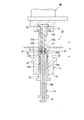
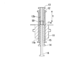
- FIG. 4 is an enlarged cross-sectional view of a main part showing a cavity of the molding die of FIG. It is an external appearance perspective view which shows the example of a shape of a molded object. It is the sectional side view which showed the molding method which concerns on embodiment of this invention. It is the sectional side view which showed the molding method which concerns on embodiment of this invention. It is the sectional side view which showed the molding method which concerns on embodiment of this invention. It is the sectional side view which showed the molding method which concerns on embodiment of this invention.
- FIG. 1 is a side sectional view along the insertion / removal direction (compression direction) of a molding die according to an embodiment of the present invention.
- FIG. 2 is a cross-sectional view taken along line A-A ′ of FIG. 3.
- the insertion / removal direction Y indicates the compression direction with respect to the cavity P by the second die 12, the first punch 13, and the second punch 14 described later.
- the molding die 10 of the present embodiment is a die for forming a green compact which is an example of a molded body by compression molding using, for example, powder as an example of an object to be molded.
- the molding die 10 includes a first die 11, a second die 12 that can be inserted into and removed from the first die 11, a first punch 13, a second punch 14, a third punch 15, and a core rod 16. .
- the first die 11 has, for example, a substantially cylindrical outer shape, and a through hole 22 penetrating between one opening 11a and the other opening 11b is formed.
- the through hole 22 forms a rectangular parallelepiped space surrounded by four inner side surfaces 22a to 22d.
- the second die 12 is a hollow rectangular tube-shaped member whose outer shape is formed in a substantially rectangular parallelepiped shape so as to be inserted into and removed from the through hole 22 of the first die 11.
- the outer surface 12a is in close contact with the inner surfaces 22a to 22d forming the through holes 22 of the first die 11 during molding.
- the second die 12 includes second die divided bodies 12A and 12B which are two divided bodies that can be divided from each other. By connecting these second die division bodies 12A and 12B to each other and inserting them into the through holes 22 of the first die 11, the contact portions of the second die division bodies 12A and 12B are brought into close contact with each other without any gap.
- dye 12 is comprised from 2nd die division body 12A, 12B of the cross-sectional U shape opposing each other.
- an undercut molding portion 32 including an uneven portion 31 extending in a direction intersecting the insertion / removal direction Y is formed on the inner wall surface 12b of the second die 12 constituting the cavity P.
- an undercut molding part 32 gives an undercut shape to the green compact in a molding method described later.
- the unevenness 31 extending in the direction intersecting with the insertion / removal direction Y here refers to a shape portion protruding or dented in a direction having an angle with respect to the insertion / removal direction Y.
- the shape, combination, and arrangement of the irregularities are not limited.
- the first punch 13 is a quadrangular prism-shaped member having a rectangular cross section formed to be detachable from the second die 12.
- the pressing surface 13a of the first punch 13 compresses the object to be molded along the insertion / removal direction Y from the one opening 11a side of the first die 11 during molding.
- the first punch 13 is formed with a through hole 13b having a circular cross section at the center of the cross section.
- a core rod 16 to be described later can be inserted into and removed from the through hole 13b.
- the first punch 13 is inserted into the through hole 22 of the first die 11 in a state where it cannot move with respect to the inner wall surface 12 b of the second die 12.
- the distance from the pressing surface 13a of the first punch 13 to the undercut molding part 32 can be made constant, and the first punch and the second die can be inserted into the through hole 22 of the first die 11, and the molded body
- the undercut shape portion 32 can be formed with high accuracy without being displaced.
- the second punch 14 is a quadrangular prism-shaped member having a rectangular cross section formed so as to be inserted into and removed from a hollow portion of the third punch 15 described later.
- the pressing surface 14a of the second punch 14 compresses the workpiece along the insertion / removal direction Y from the other opening 11b side of the first die 11 during molding.
- the second punch 14 has a through hole 14b having a circular cross section at the center of the cross section. This through hole 14b is formed coaxially with the same diameter as the through hole 13b of the first punch 13, and a part of a core rod 16 described later can be inserted and removed.
- the third punch 15 is a hollow rectangular tube-shaped member whose outer shape is formed in a substantially rectangular parallelepiped shape so as to be inserted into and removed from the through hole 22 of the first die 11.
- the third punch 15 is in contact with the inner side surfaces 22a to 22d of which the outer surface 15a forms the through hole 22 of the first die 11 during molding.
- the tip 15 b is in contact with the lower end of the second die 12. Accordingly, the second die 12 can be raised, for example, by moving the third punch 15 relative to the first die 11. Further, the above-described second punch 14 can be inserted into and removed from the hollow portion of the third punch 15.
- the core rod 16 is, for example, a cylindrical rod-like member, and is detachably arranged so as to penetrate through the cavity P from the through hole 14 b of the second punch 14 toward the through hole 13 b of the first punch 13. .
- Such a core rod 16 forms a through hole having a circular cross section with respect to the green compact molded in the cavity P.
- FIG. 3 is a side sectional view showing a state at the time of molding of the molding die shown in FIG. 4 is an enlarged cross-sectional view of a main part showing the cavity P and its peripheral part in FIG.
- a cavity P surrounded by the second die 12, the first punch 13 and the second punch 14 is formed in the through hole 22 of the first die 11. More specifically, the cavity P is a substantially rectangular parallelepiped molding space surrounded by the inner wall surface 12b of the second die 12, the pressure surface 13a of the first punch 13, and the pressure surface 14a of the second punch 14.
- the second die 12 covers the inner side surfaces 22a to 22d forming the through hole 22 of the first die 11. As a result, the inner surfaces 22a to 22d forming the through hole 22 are not exposed to the cavity P.
- An undercut molding portion 32 is formed on the inner wall surface 12 b facing the cavity P of the second die 12. Further, the core rod 16 passes through the central portion of the cavity P along the insertion / removal direction Y.
- the cavity P is filled with the powder W, which is a molding object, and the first punch 13 is directed toward the second punch 14 by the pressurizing mechanism 40 including a hydraulic device or the like. It moves, narrows the height along the insertion / removal direction Y of the cavity P, compresses the powder W that is the molding object, and molds the green compact that represents the shape of the cavity P.
- FIG. 5 is an external perspective view showing an example of a green compact (molded body) formed using the molding die 10 having such a configuration.
- the green compact 50 has a substantially rectangular parallelepiped shape, and a through hole 51 having a rectangular cross section formed by the core rod 16 (see FIGS. 1 and 2) is provided at the center.
- a groove (undercut shape portion) 52 having a substantially trapezoidal cross section formed by the unevenness 31 (see FIGS. 1 and 2) forming the undercut molding portion 32 is formed on one surface of the green compact 50. It is formed over the entire circumference of the four side surfaces 53.
- the groove 52 is an undercut shape portion extending in a direction intersecting with the insertion / removal direction Y when the green compact 50 is molded.
- FIG. 6A, FIG. 6B, FIG. 6C, FIG. 7A, and FIG. 7B are sectional side views showing the molding method of the present invention step by step. 7A and 7B also show an upper cross-sectional view when the molding die is viewed from above.
- the third punch 15 is inserted into the through hole 22 from the other opening 11 b of the first die 11, and the second punch 14 is inserted into the hollow portion of the third punch 15.
- the second punch 14 is set such that the pressure surface 14 a is lower in the insertion / removal direction Y than the tip 15 b of the third punch 15.
- the core rod 16 is inserted into the through hole 14 b of the second punch 14.
- powder W which is an example of a molding object, is introduced into the through hole 22 of the first die 11 (in the third punch 15 inserted into the through hole 22).
- the powder W is introduced into the hollow portion of the third punch 15 before molding.
- the powder W to be introduced include iron powder and copper powder containing metal as a main component, and mixed powder thereof.
- the pressurizing mechanism 40 (see FIG. 3) is operated to lower the second die 12 with the first punch 13 fitted therein, and penetrates through the opening 11 a of the first die 11.
- the first punch 13 and the second die 12 are inserted into the hole 22 at the same time.
- the powder W is filled in the cavity P surrounded by the inner wall surface 12b of the second die 12, the pressing surface 13a of the first punch 13, and the pressing surface 14a of the second punch 14 (molded object). Filling step).
- the second die divided body 12A and the second die divided body 12B constituting the second die 12 are coupled to each other and inserted into the through-hole 22 of the first die 11, so that the second die divided body 12A and The divided portion with the second die divided body 12B is in close contact with no gap.
- the first punch 13 is further lowered toward the second punch 14 by the pressing mechanism 40 (see FIG. 3), and the space between the pressing surface 13a of the first punch 13 and the pressing surface 14a of the second punch 14 is narrowed.
- the powder W is compressed (compression process).
- the powder W is compressed in the cavity P, and the groove 52 (see FIG. 5) forming the undercut shape portion that represents the internal shape of the cavity P and the through hole 51 (see FIG. 5) that represents the core rod 16.
- the green compact (molded body) 50 provided with the structure shown in FIG. 5 is compression-molded.
- the compressed powder When the powder W is compressed, the compressed powder is pressed against the undercut molding portion 32 (see FIG. 4) of the second die 12 and has a trapezoidal cross section 31 that extends in the direction intersecting the insertion / removal direction Y ( 4) is transferred. Thereby, a groove 52 which is an undercut shape portion having a trapezoidal cross section is formed in the green compact (molded body) 50 so as to surround the entire side surface of the green compact 50.
- the second punch 14, the third punch 15, the second die 12 holding the green compact 50, and the first punch 13. Is extracted from the through hole 22 of the first die 11 (extraction step).
- the green compact 50 is held on the inner wall surface 12 b of the second die 12.
- the second die 12 and the first punch 13 holding the green compact 50 are completely extracted from the through hole 22 of the first die 11.
- the green compact 50 is in a state where the groove 52 is engaged with the undercut molding portion 32.
- the second die divided body 12A and the second die divided body 12B constituting the second die 12 are separated. Specifically, with the second die divided body 12A fixed, the second die divided body 12B is moved along the direction intersecting the insertion / removal direction Y by the die moving device 55, for example, along the horizontal direction L, for example.
- the second die divided body 12A and the second die divided body 12B constituting the second die 12 are relatively moved along the horizontal direction L so that the second die divided body 12A intersects the insertion / removal direction Y.
- the green compact 50 (see FIG. 5) can be released from the second die 12 without damaging the groove 52 (see FIG. 5) which is an extended (concave) undercut shape portion.
- channel 52 which is an undercut shape part can be shape
- the second die 12 having the undercut molding portion 32 is simply inserted into the through hole 22 of the first die 11 and molded.
- a highly accurate undercut shape portion (the groove 52 in the present embodiment) can be easily formed on the entire circumference of the side surface of the (molded body) 50.
- the second die 12 is composed of second die division bodies 12A and 12B that can be divided from each other. After the green compact 50 is molded, the second die 12 extends along a direction different from the insertion / removal direction Y, for example, the horizontal direction L. By dividing the divided body 12A and the second die divided body 12B, the green compact 50 can be easily released from the second die 12 without damaging the groove 52 which is the undercut shape portion. The green compact 50 having a highly accurate undercut shape can be formed.
- the powder W (molded article) is introduced into the through hole 22 of the first die 11 in advance, and then the through hole 22 of the first die 11 is attached to the first punch 13.
- the second die 12 having the undercut molding portion 32 is inserted into the first die 11 so as to be in close contact with the outer surface 12a of the second die 12, and then the powder W is added.
- the adhesion of the divided surfaces of the second die divided body 12A and the second die divided body 12B constituting the second die 12 can be enhanced.
- the powder does not enter the dividing surface of the second die divided body 12A and the second die divided body 12B, and the green compact (molded body) 50 burr does not occur, and the precise green compact (molded body) ) 50 can be obtained.
- the second die 12 having the undercut molding portion 32 is inserted into the first die 11 so as to be in close contact with the outer surface 12a of the second die 12, thereby compressing.
- the breakage of the second die 12 to which a strong pressure is sometimes applied can be prevented.
- the second die 12 is formed so as to be divided into two in the horizontal direction L.
- the second die 12 can be divided into three or more parts.
- a green compact having an undercut shape composed of a plurality of types of unevenness having different directions intersecting with the insertion / removal direction Y can be molded.
- the second die 12 may be divided into two in the horizontal direction L and then divided into two in the insertion / removal direction Y.
- the molding object is limited to powder. It is not what is done.
- this solid material is introduced into the cavity P of the molding die of the present invention and molded into a predetermined shape. Can be applied.
- various forms such as lumps and granules can be used as the moldings.
- the green compact (molded body) 50 is exemplified as having a substantially rectangular parallelepiped shape, but the molded body obtained by the molding die and molding method of the present invention is not limited to such a shape. No. Hereinafter, some of the moldings obtained by the molding die and molding method of the present invention will be exemplified with reference to the drawings.
- the molded body 60 shown in FIG. 8 has a substantially cylindrical outer shape, and a trapezoidal groove 61 serving as an undercut shape portion is formed over the entire circumference of the peripheral side surface 62.
- a through hole 63 is formed in the central portion.
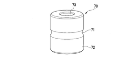
- the molded body 70 shown in FIG. 9A has a substantially cylindrical outer shape, and one groove 71 having a semicircular cross section serving as an undercut shape portion is formed over the entire circumference of the peripheral side surface 72. A through hole 73 is formed in the center portion.
- the molded body 75 shown in FIG. 9B has a substantially cylindrical outer shape, and has two semicircular grooves 76 a and 76 b that are undercut shape portions formed in parallel with each other over the entire circumference of the peripheral side surface 77. Yes.
- a through hole 78 is formed in the central portion.
- the molded body 80 shown in FIG. 9C has a substantially cylindrical outer shape, and flat surfaces 81a and 81b facing each other are formed. And the groove
- FIG. A through hole 84 is formed in the center portion.
- the molded body 85 shown in FIG. 10A has a substantially cylindrical outer shape, and a large number of rectangular grooves 86 serving as undercut portions are arranged at predetermined intervals over the entire circumference of the peripheral side surface 87.
- a through hole 88 is formed in the center portion.
- a molded body 90 shown in FIG. 10B has a substantially cylindrical outer shape, and a groove 91 having a shape in which a large number of cross-shaped grooves serving as undercut shapes are connected is formed over the entire circumference of the peripheral side surface 92. Yes. A through hole 93 is formed in the central portion.
- the molded body 100 shown in FIG. 11A has a substantially plate shape with a square outer shape, and is formed over the entire circumference so that a groove 101 having a semicircular cross section serving as an undercut shape portion straddles four peripheral side surfaces 102. Yes.
- a through hole 103 is formed in the central portion.
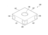
- the molded body 105 shown in FIG. 11B has a substantially plate shape with a square outer shape, and a semicircular groove 106 serving as an undercut shape portion is formed at each of four corners where four circumferential side surfaces 107 intersect. Yes.
- a through hole 108 is formed in the central portion.
- Each shape of the molded body listed above is an example, and the shape of the molded body obtained by the molding die and the molding method of the present invention is not limited.
- the undercut shape portion can be molded with high accuracy without being displaced.
Landscapes
- Engineering & Computer Science (AREA)
- Mechanical Engineering (AREA)
- Manufacturing & Machinery (AREA)
- Powder Metallurgy (AREA)
Priority Applications (3)
| Application Number | Priority Date | Filing Date | Title |
|---|---|---|---|
| CN201780031157.2A CN109153075B (zh) | 2016-08-18 | 2017-08-15 | 成型模具及成型方法 |
| US16/306,349 US11446737B2 (en) | 2016-08-18 | 2017-08-15 | Molding die and molding method |
| EP17841510.5A EP3501693A4 (en) | 2016-08-18 | 2017-08-15 | MOLDING MATRIX AND MOLDING METHOD |
Applications Claiming Priority (2)
| Application Number | Priority Date | Filing Date | Title |
|---|---|---|---|
| JP2016160554A JP6796433B2 (ja) | 2016-08-18 | 2016-08-18 | 成型金型、成型方法 |
| JP2016-160554 | 2016-08-18 |
Publications (1)
| Publication Number | Publication Date |
|---|---|
| WO2018034288A1 true WO2018034288A1 (ja) | 2018-02-22 |
Family
ID=61196671
Family Applications (1)
| Application Number | Title | Priority Date | Filing Date |
|---|---|---|---|
| PCT/JP2017/029386 Ceased WO2018034288A1 (ja) | 2016-08-18 | 2017-08-15 | 成型金型、成型方法 |
Country Status (5)
| Country | Link |
|---|---|
| US (1) | US11446737B2 (https=) |
| EP (1) | EP3501693A4 (https=) |
| JP (1) | JP6796433B2 (https=) |
| CN (1) | CN109153075B (https=) |
| WO (1) | WO2018034288A1 (https=) |
Families Citing this family (1)
| Publication number | Priority date | Publication date | Assignee | Title |
|---|---|---|---|---|
| US12251277B2 (en) * | 2022-02-04 | 2025-03-18 | Dentsply Sirona Inc. | Method for producing a multi-layer blank with a through-hole |
Citations (2)
| Publication number | Priority date | Publication date | Assignee | Title |
|---|---|---|---|---|
| JPH0285304A (ja) * | 1988-09-20 | 1990-03-26 | Hitachi Powdered Metals Co Ltd | ボス付き成形体の粉末成形方法およびその装置 |
| JPH0639596A (ja) * | 1992-07-28 | 1994-02-15 | Yoshitsuka Seiki:Kk | アンダーカット部を有する粉末成形品の製造方法および装置 |
Family Cites Families (32)
| Publication number | Priority date | Publication date | Assignee | Title |
|---|---|---|---|---|
| US3615382A (en) * | 1968-08-29 | 1971-10-26 | Int Nickel Co | Production of tubular products from metallic powders |
| JPS528551B2 (https=) | 1971-11-29 | 1977-03-10 | ||
| JPS51149106A (en) | 1975-06-18 | 1976-12-21 | Hitachi Powdered Metals Co Ltd | A powder molding means |
| US4087221A (en) | 1977-01-31 | 1978-05-02 | Remington Arms Company, Inc. | Apparatus for molding powder metal parts |
| SU1041209A1 (ru) * | 1982-02-25 | 1983-09-15 | Предприятие П/Я Р-6205 | Пресс-форма дл прессовани изделий из порошка |
| JPS5943106U (ja) | 1982-09-16 | 1984-03-21 | 曙ブレーキ工業株式会社 | 粉末成形品製造用金型 |
| JPH01100206A (ja) | 1987-10-12 | 1989-04-18 | Komatsu Ltd | 粉末成形法 |
| JP3003126B2 (ja) | 1992-04-24 | 2000-01-24 | 三菱マテリアル株式会社 | 粉末成形方法 |
| US5378416A (en) | 1992-07-28 | 1995-01-03 | Nissan Motor Co., Ltd. | Method of and system for manufacturing powder moldings |
| CA2154556C (en) * | 1993-11-24 | 2006-02-21 | Gerd Hinzmann | Undercut split die |
| DE69325924T2 (de) * | 1993-11-24 | 2000-02-17 | Stackpole Ltd., Mississauga | Versetzte mehrteilige pressform |
| JPH0820807A (ja) * | 1994-07-06 | 1996-01-23 | Hitachi Powdered Metals Co Ltd | 圧粉体の成形方法 |
| US5503795A (en) | 1995-04-25 | 1996-04-02 | Pennsylvania Pressed Metals, Inc. | Preform compaction powdered metal process |
| JP3531151B2 (ja) | 1998-01-06 | 2004-05-24 | 三菱マテリアル株式会社 | オルダムリングの製造に用いる粉末成形用金型装置 |
| CA2303683A1 (en) * | 2000-04-03 | 2001-10-03 | F. George Pataracchia | Multifunction split powder metal die |
| WO2003008131A2 (en) * | 2001-07-20 | 2003-01-30 | Hawk Precision Components Group, Inc. | Apparatus and method for high-velocity compaction of multiple-level parts |
| JP3980348B2 (ja) | 2001-12-21 | 2007-09-26 | 三菱マテリアルPmg株式会社 | 焼結製品、焼結製品の成形方法および成形用金型 |
| SE0203475A0 (en) * | 2002-01-25 | 2003-07-26 | Ck Man Ab | A method and an apparatus for producing multi-level or stepped components for shock (impact) compression of powdered material |
| JP4443847B2 (ja) | 2003-03-31 | 2010-03-31 | 日立粉末冶金株式会社 | 傘状粉末成形体の成形方法 |
| CN2877916Y (zh) * | 2006-03-17 | 2007-03-14 | 庄海君 | 液压制动总泵活塞模具 |
| WO2008118773A1 (en) * | 2007-03-23 | 2008-10-02 | Gkn Sinter Metals, Llc | Powder metal bearing cap breathing windows |
| US7829015B2 (en) | 2007-05-31 | 2010-11-09 | Borgwarner Inc. | Formation of non-axial features in compacted powder metal components |
| JP5352978B2 (ja) | 2007-09-11 | 2013-11-27 | 株式会社ダイヤメット | 焼結軸受の製造方法 |
| US8062014B2 (en) | 2007-11-27 | 2011-11-22 | Kennametal Inc. | Method and apparatus using a split case die to press a part and the part produced therefrom |
| JP5070626B2 (ja) * | 2008-07-30 | 2012-11-14 | 住友電工焼結合金株式会社 | 粉末成形用金型 |
| BR112012001378B1 (pt) | 2009-07-23 | 2020-12-08 | Gkn Sinter Metals, Llc | limitador de compressão, e, método para formar um limitador de compressão |
| JP5548588B2 (ja) * | 2010-10-29 | 2014-07-16 | 日立粉末冶金株式会社 | 微小部品の成形金型装置 |
| CN202291399U (zh) | 2011-09-01 | 2012-07-04 | 南通华兴磁性材料有限公司 | 一种eer型锰锌铁氧体磁芯模具 |
| DE102014003726A1 (de) * | 2014-03-18 | 2015-09-24 | Gkn Sinter Metals Engineering Gmbh | Presse zum Herstellen maßhaltiger Grünlinge und Verfahren zum Herstellen |
| DE102014008169A1 (de) * | 2014-06-10 | 2015-12-17 | Gkn Sinter Metals Engineering Gmbh | Verfahren und Presse zur Herstellung eines Grünlingsverbundes mit einer Sollbruchstelle |
| CN104014787A (zh) | 2014-06-19 | 2014-09-03 | 山西东睦华晟粉末冶金有限公司 | 多台阶粉末冶金零件一次成型模具和成型方法 |
| CN205008573U (zh) | 2015-08-19 | 2016-02-03 | 宁波凌珂新材料科技有限公司 | 具有沟槽的粉末成形件的压制装置 |
-
2016
- 2016-08-18 JP JP2016160554A patent/JP6796433B2/ja active Active
-
2017
- 2017-08-15 CN CN201780031157.2A patent/CN109153075B/zh active Active
- 2017-08-15 US US16/306,349 patent/US11446737B2/en active Active
- 2017-08-15 EP EP17841510.5A patent/EP3501693A4/en not_active Withdrawn
- 2017-08-15 WO PCT/JP2017/029386 patent/WO2018034288A1/ja not_active Ceased
Patent Citations (2)
| Publication number | Priority date | Publication date | Assignee | Title |
|---|---|---|---|---|
| JPH0285304A (ja) * | 1988-09-20 | 1990-03-26 | Hitachi Powdered Metals Co Ltd | ボス付き成形体の粉末成形方法およびその装置 |
| JPH0639596A (ja) * | 1992-07-28 | 1994-02-15 | Yoshitsuka Seiki:Kk | アンダーカット部を有する粉末成形品の製造方法および装置 |
Non-Patent Citations (1)
| Title |
|---|
| See also references of EP3501693A4 * |
Also Published As
| Publication number | Publication date |
|---|---|
| EP3501693A1 (en) | 2019-06-26 |
| US20190344349A1 (en) | 2019-11-14 |
| EP3501693A4 (en) | 2020-01-01 |
| CN109153075A (zh) | 2019-01-04 |
| JP2018028132A (ja) | 2018-02-22 |
| JP6796433B2 (ja) | 2020-12-09 |
| CN109153075B (zh) | 2021-07-09 |
| US11446737B2 (en) | 2022-09-20 |
Similar Documents
| Publication | Publication Date | Title |
|---|---|---|
| RU2602310C2 (ru) | Устройство и способ изготовления режущих пластин | |
| ATE483569T1 (de) | Verfahren zur herstellung einer vulkanisierform mit mehreren zu einer umfangsmässig geschlossenen form zusammenfügbaren profilsegmenten und vulkanisierform | |
| WO2018034288A1 (ja) | 成型金型、成型方法 | |
| JP7018494B2 (ja) | 成型金型、成型方法 | |
| JP5543753B2 (ja) | 微小歯車の粉末成形体成形方法 | |
| CN210877549U (zh) | 一种粉末冶金制作圆棒易于脱模的模具 | |
| JP2010007154A (ja) | 焼結部品の圧粉体成形方法および圧粉体成形金型 | |
| CN105312586B (zh) | 用于制造滑动套筒的方法 | |
| WO2017154775A1 (ja) | 成型金型、成型方法 | |
| JP2008208388A (ja) | 成形用金型 | |
| KR101880293B1 (ko) | 소결성형제품 제조 장치 및 인출 방법 | |
| CN104384513B (zh) | 粉末冶金侧孔成形模具 | |
| JP5862927B2 (ja) | 湾曲板状部品の圧粉体成形金型装置 | |
| JP2002045998A (ja) | プレス成形機 | |
| JP2006181605A (ja) | 粉末成形装置および圧粉体の製造方法 | |
| JP3878568B2 (ja) | 粉未成形体の製造方法並びに成形金型 | |
| CN204308203U (zh) | 粉末冶金侧孔成形模具 | |
| JP4099508B2 (ja) | 成形用ダイス | |
| JP4394257B2 (ja) | 粉末成形体の製造方法 | |
| JP2007222879A (ja) | 粉末成形用金型及び粉末成形方法 | |
| JP4523121B2 (ja) | 粉末成形体の製造方法 | |
| JP6329106B2 (ja) | 軸受の製造方法 | |
| CN203804190U (zh) | 一种机外脱模的压铸模结构 | |
| JP2008246567A (ja) | 粉末成形装置および粉末成形方法 | |
| JP5366320B2 (ja) | 成形体の成形方法 |
Legal Events
| Date | Code | Title | Description |
|---|---|---|---|
| 121 | Ep: the epo has been informed by wipo that ep was designated in this application |
Ref document number: 17841510 Country of ref document: EP Kind code of ref document: A1 |
|
| NENP | Non-entry into the national phase |
Ref country code: DE |
|
| ENP | Entry into the national phase |
Ref document number: 2017841510 Country of ref document: EP Effective date: 20190318 |